June 2013
101
Transcript of June 2013


circle 100 on card or go to psfreeinfo.com

2 June 2013 www.pump-zone.com PUMPS & SYSTEMS
From the Editor
PUMPS & SYSTEMS (ISSN# 1065-108X) is published monthly Cahaba Media Group, 1900 28th Avenue So., Suite 110, Birmingham, AL 35209. Periodicals postage paid at Birmingham, AL, and additional mailing offi ces. Subscriptions: Free of charge to qualifi ed industrial pump users. Publisher reserves the right to determine qualifi cations. Annual subscriptions: US and possessions $48, all other countries $125 US funds (via air mail). Single copies: US and possessions $5, all other countries $15 US funds (via air mail). Call (630) 739-0900 inside or outside the U.S. POSTMASTER: Send changes of address and form 3579 to Pumps & Systems, Subscription Dept., 440 Quadrangle Drive, Suite E, Bolingbrook, IL 60440. ©2013 Cahaba Media Group, Inc. No part of this publication may be reproduced without the written consent of the publisher. The publisher does not warrant, either expressly or by implication, the factual accuracy of any advertisements, articles or descrip-tions herein, nor does the publisher warrant the validity of any views or opinions offered by the authors of said articles or descriptions. The opinions expressed are those of the individual authors, and do not necessarily represent the opinions of Cahaba Media Group. Cahaba Media Group makes no representation or warranties regarding the accuracy or appropriateness of the advice or any advertisements contained in this magazine. SUBMISSIONS: We welcome submissions. Unless otherwise negotiated in writing by the editors, by sending us your submission, you grant Cahaba Media Group, Inc., permission by an irrevocable license to edit, reproduce, distribute, publish and adapt your submission in any medium on multiple occasions. You are free to publish your submission yourself or to allow others to republish your submission. Submissions will not be returned. Volume 21, Issue 6.
is a member of the following organizations:
More than half of all electrical energy con-sumed in the U.S. is used by electric motors,
according to the Department of Energy (DOE). Federal law requires most general motors sold after October 1997 to meet or exceed the National Electric Manufacturers Association’s (NEMA) defi nition of energy effi cient—2 to 8 percent more effi cient than standard motors.
A coalition of nine associations, including NEMA, Appliance Standards Awareness Project (ASAP) and the American Council for an Energy-Effi cient Economy (ACEEE) met with the DOE on May 13 for an update on an August 2012 petition that recommended specifi c energy conservation standards for electric motors.
According to NEMA Industry Director William Hoyt, the petition off ers a solution that would achieve the DOE’s goals for energy sav-ings but will lessen the stress on the industry’s end users and manufacturers.
“h e proposed DOE upgrades will require motors to be made with more material to create a bigger frame,” Hoyt said. “h e diameter is larger and longer and will no longer fi t into the pre-engineered space. It will also require changes to the electrical circuits. Our petition provides a solution for more energy savings but one that is easier for end users and OEMs to implement.”
h e DOE reports that key design improve-ments and more accurate manufacturing
tolerances have contributed to the higher perfor-mance of energy-effi cient motors. Lengthening the core and using lower-electrical-loss steel, thinner stator laminations and more copper in the windings can reduce electrical losses. Improved bearings and a smaller, more aerody-namic cooling fan can further increase effi ciency.
Hoyt said that NEMA believes there is an easier way to increase the effi ciency level using existing products. He also emphasized that the motor ruling will be the beginning of the frame-work for an early investigation into improved pumping system standards.
h e Small Motor Rule is proceeding for March 9, 2015, adoption. A NEMA white paper on the details of this topic is available through a link on my blog on www.pump-zone.com, along with additional updates that happened after this issue’s press time. Look for a more detailed article in an upcoming issue of Pumps & Systems.
h is month’s cover series (page 28) features articles about motor nameplate letter code des-ignations, the importance of clearance on bear-
ing life, effi ciency, electric motor repair and reliability and VFDs in pump applications. Visit us at Booth #826 at EASA in Las Vegas, June 30 – July 2.
Thomas L. Angle, P.E., MSc, Vice President Engineering, HidrostalAG
Robert K. Asdal, Executive Director, Hydraulic Institute
Bryan S. Barrington, Machinery Engineer, Lyondell Chemical Co.
Kerry Baskins, Vice President of Sales, Viking Pump
Walter Bonnett, Vice President Global Marketing, Pump Solutions Group
R. Thomas Brown III, President, Advanced Sealing International (ASI)
Chris Caldwell, Director of Advanced Collection Technology, Business Area Wastewater Solutions,Sulzer Pumps, ABS USA
Jack Creamer, Market Segment Manager-Pumping Equipment, Square D by Schneider Electric
Bob Domkowski, Business Development Manager – Transport Pumping and Amusement Markets / Engineering Consultant, Xylem, Inc., Water Solutions USA – Flygt
David A. Doty, North American Sales Manager, Moyno Industrial Pumps
Walt Erndt, Director of Market Development SSB, Environment One Corporation
Joe Evans, Ph.D., Customer & Employee Education, PumpTech, Inc.
Ralph P. Gabriel, Chief Engineer—Global, John Crane
Bob Langton, Vice President, Industry Sales, Grundfos Pumps
Larry Lewis, President, Vanton Pump and Equipment Corp.
Todd Loudin, President/CEO North American Operations, Flowrox Inc.
John Malinowski, Sr. Product Manager, AC Motors, Baldor Electric Company, A Member of the ABB Group
William E. Neis, P.E., President, Northeast Industrial Sales
Lev Nelik, Ph.D, P.E., APICS, President, Pumping Machinery, LLC
Henry Peck, President, Geiger Pumps & Equipment/Smith-Koch, Inc.
Mike Pemberton, Manager, ITT Performance Services
Scott Sorensen, Oil & Gas Automation Consultant & Market Developer, Siemens Industry Sector
Adam Stolberg, Executive Director, Submersible Wastewater Pump Association (SWPA)
Bruce Stratton, Product Manager, KLOZURE®, Garlock Sealing Technologies
Kirk Wilson, President, Services & Solutions, Flowserve Corporation
PublisherWalter B. Evans, Jr.
VP of SalesGeorge Lake
[email protected] • 205-345-0477
VP of EditorialMichelle Segrest
[email protected] • 205-314-8279
Creative DirectorTerri Jackson
EDITORIAL
EditorMichelle Segrest
[email protected] • 205-314-8279
Managing EditorLori K. Ditoro
[email protected] • 205-314-8269
Associate EditorAmanda Perry
[email protected] • 205-314-8274
Contributing EditorsLaurel DonohoJoe Evans, Ph.D.
Lev Nelik, Ph.D., PE, APICS
CREATIVE SERVICES
Creative DirectorTerri Jackson
Senior Art DirectorGreg Ragsdale
Art DirectorJaime DeArman
PRODUCTION
Print Advertising Traffi cLisa Freeman
[email protected] • 205-212-9402
Web Advertising Traffi cAshley Morris
[email protected] • 205-561-2600
CIRCULATION
Jeff [email protected] • 630-739-0900
ADVERTISING
Derrell [email protected] • 205-345-0784
Mary-Kathryn [email protected] • 205-345-6036
Mark [email protected] • 205-345-6414
Addison [email protected] • 205-561-2603
Vince [email protected] • 205-561-2601
P.O. Box 530067Birmingham, AL 35253
Editorial & Production1900 28th Avenue South, Suite 110
Birmingham, AL 35209Phone: 205-212-9402
Advertising Sales2126 McFarland Blvd. East,. Suite A
Tuscaloosa, AL 35404Phone: 205-345-0477 or 205-561-2600
Editorial Advisory Board

circle 112 on card or go to psfreeinfo.com

4 June 2013 www.pump-zone.com PUMPS & SYSTEMS
Table of Contents June 2013Volume 21 • Number 6
6 20th Anniversary Top 20 List By Amanda Perry
Top 20 Pump Industry Trade Shows
10 News
68 Effi ciency MattersBy Edison BritoATEX: The Symbol of Safety in Dangerous
Chemicals Handling
72 Sealing SenseBy The Fluid Sealing AssociationImproved Torque Tension
76 HI Pump FAQsBy The Hydraulic InstituteOutdoor Installations, Rotodynamic Vertical
Pumps & Drooping Head
80 Business of the BusinessBy Sakthi Pandian & Anand Gnanamoorthy, Frost & SullivanFood & Beverage Industry Pump Market
89 Product Pipeline
96 Pump Market AnalysisBy Jordan, Knauff & Company
83 Rotary Lobe Pumps in Sugar Processing
By Marino Curati, VogelsangThis pump type manages the temperature and viscosity challenges of handling this diffi cult product.
86 Peristaltic Pump Speed ConsiderationsBy Todd Loudin, Flowrox Inc.Operating speed requirements must be a factor when selecting a pump.
Departments
29 Motor Nameplate Letter Code DesignationsBy Thomas H. Bishop, P.E., EASALearn how to avoid misinterpretations.
32 Internal Clearance & Its Effect on Bearing Fatigue LifeBy Miles Woodard and Ryan Thomas, NSKEnd users must include bearing clearance as an integral part of designing or building a pump.
40 Long-Term Motor Reliability By Timothy Albers and Steve Hauck, Nidec Motor CorporationA variable frequency drive’s effect on system effi ciency and motor life
44 Electric Motor Repair and ReliabilityBy Howard W. Penrose, Dreisilker Electric Motors, Inc.Repetitive motor failures may be caused by a lack of diagnostic or forensic repair information reported to the motor owner.
50 VFDs Save Energy in Pump Applications By Tom Neuberger, EatonUsing variable frequency drives provides many benefi ts to end users.
Pump Repair & Maintenance
Columns16 Pump Ed 101
By Joe Evans, Ph.D.
Why Wye? Why Delta?
20 Pumping PrescriptionsBy Lev Nelik, Ph.D., P.E.,
Pumping Machinery, LLC
Do Vibration Measurements Depend
on Probe Placement and Probe Type?
2 From the Editor
54 Trade Show Coverage
92 Index of Advertisers
92 Pump Users Marketplace
COVER
SERIES
Motors & Drives
Practice & Operations
57 Reverse Engineering of a Vertical Pump Suction BowlBy Jeff Smith, Hydro Parts Solutions Inc., & Dr. T. Ravisundar & Werner Barnard, HydroAire Inc.The pump was returned to service at a nuclear power plant after reverse engineering of an unavailable part and complete pump testing.
62 Maintenance Minders: Root Cause Analysis &
Problem SolvingBy Chris Eckert, SologicBasic solutions that limit the involve-ment of a slowly dwindling staff are ideal in today’s workplace.
SPECIAL
SECTION
2828
5656Ph
oto
cour
tesy
of W
EG E
lect
ric C
orp

Reliable, cost-effective surface pumpingwith no daily maintenance.
REDAREEREREREDAEDAREDAEDREREDAEDAREDAREDAREDAEDAAREDAREDAREDAREDAEDAEDAREDADDEDAREDAREDAEDARRREDAREDAAAEDAREREDADAAAREDAEDAREDAREDAREDAREDAREDAAARRRREDDAAAREDARREDDDAAREDAREDAR DAAAARREDAAAAREDADAAAREDAAAAAREDAAR DAAADDDAAAAAREDAAAADAAA HPSHPSHPSHPSHPSPHPSHPSHPSHHPSHPSPHPPSSSSHPSHPSHPSPSSHPSHPSHPSHPSHPSHPSSHPSPHPHPHPPHPPHPSHPHHHHPPHPHPSHHPSHPSPSSHPSPPH isisisisisisisisiisisisisssisssisssisisisiissisiis aaaaa mmmaa maa maa maaaa ma maa maaa ma maa mmaaaa aa mmaaaa mma ma maaaaa maa maa ma maa a maaa rk orkrk ork ork ok ok ork ok ok ooorkrk ok ork ork ork ok ok orrk ok ok orrk ok ok ork orrk ork oooooor ooook ok ooof Sfff Sf Scf Scf Scf Sff Scf Sc Sf ScScS Scf Scf Scfff SScf Scff Sf Sf SScSccff Scf Scff Sf Sf ff Sf SSf Sf SSSff f Scff Sf hlumhhlumhlumhlumlumlumumumhlumumumhhhlumhhlumhhlumuuuuuumuuumbergbergbergbergbergergbergrgbergerergergergbergerergergergbergbeergergergggbe gbeebeeebee ererer. erer.ererer.er.er. eerrerer.er. rrrer.rer.rrrreerreer.ereer.eer. ©©©©©©©©©©©©©©©©©©©©© 20101020120120120120202010201220202020202010101010100200011201200202010000013 Sc3 Sc3 Sc3 S3 Sc3 ScS3 S3 Sc33 ScSc3 Sc3 Sc3 SSSc3 S3 S3 S3 ScS33 SSc3 Sc3 SSSc3 Sc3 Schhluhlumhlhluhlumhlumhlumh umhlumhlummumumhluhlummmmumhlumhlh bbbebbergbergbergbergbergbergberggbbbbergbergergrgbergergbbergbereberbebergrbergbebberbergbbb ggger. er.erer. er. er. er.er.er. er. er. er. ereeerer. 1111111111111111113-A3-AL3-AL3-AL3-AL3-A3-AL3 AL3 AL3-ALL3 AL3-AL3-AL3 AL3-AAL3-ALLL3-AL33-AL3-AL3-ALAL3-AL3-A3-AAA3-A3-AL3-ALL3-ALA33 ALLLL-003-00-003-003-003-003-003-003003-003-003-003-003-003-003-000-00-003-00333-00000003-0030003-003-00-003-003--003000000000000000000000
A proven alternative to split case, vertical turbine, and positive displacement pumps, the
REDA HPS G3 pumping system features a modular design that is delivered quickly and preassembled
to the site. All major components of the lexible unit can be replaced in the ield within 2 to 3 hours.
These reliable pumps have provided MarkWest more than 5 years of cost-effective NGL production,
achieving trouble-free operation with no downtime other than scheduled oil changes.
HORIZONTAL MULTISTAGE
SURFACE PUMPS
REDA HPS G3
Find out more at
slb.com/redahps
circle 108 on card or go to psfreeinfo.com

6 June 2013 www.pump-zone.com PUMPS & SYSTEMS
Top 20 Pump Industry Trade Shows Pumps & Systems readers told us about their favorite pump industry trade shows. The second part of the Top 20 list is provided here, in alphabetical order. View the full slideshow with all 20 favorites on www.pump-zone.com.
Second of Two Parts
By Amanda Perry
YEARS1 9 9 3 - 2 0 1 3
Chem ShowChemical & Process Industry
New York, N.Y.
Occurs every 2 years
www.chemshow.com
h e Chem Show is an event for process industry profes-sionals. Attendees have the opportunity to learn about the latest process equipment, systems and products and attend comprehensive educational programs that provide informa-tion on how to increase process ei ciency, reduce costs and develop more sustainable operations.
ConExpoConstruction Industry
Las Vegas, Nev.
Occurs every 3 years
www.conexpoconagg.com
More than 130,000 construction professionals attend ConExpo—including contractors, dealers, distributors, ser-vice providers, engineers, producers and municipalities—to learn about the latest technologies.
INTERPHEXPharmaceutical and
Biopharmaceutical Industry
New York, N.Y.
Annual event
www.interphex.com
INTERPHEX is an annual pharmaceutical and biophar-maceutical trade show that provides networking opportu-nities, products, services and information to ensure quality and solve manufacturing and supply chain problems.
MINExpo InternationalMining Process Industry
Las Vegas, Nev.
Occurs every 4 years
www.minexpo.com
MINExpo is sponsored by the National Mining Association and exhibits mining and minerals processing technologies, machinery and equipment for the coal, metal and nonmetal mining processing industries.
NACS/PEI ShowConvenience and
Fuel Retail Industry
Location changes each year
Annual event
www.nacsonline.com
Professionals from the convenience and fuel retailing industry attend this four-day event for educational sessions, products and networking.
“NACS/PEI show is awesome. h ere are many educa-tional and networking opportunities.”Ian Pickering, Marketing Director Dixon Pumps, Billings, Mont.
NGWAGroundwater Industry
Location changes each year
Annual event
www.ngwa.org
h is show for groundwater professionals provides educa-tional, networking and business opportunities for water well drillers, contractors, manufacturers, suppliers, scien-tists and engineers.

PUMPS & SYSTEMS www.pump-zone.com June 2013 7
Oil Sands Trade Show
and Conference
Oil & Gas Industry
Fort McMurray, Alberta, Canada
Annual event
www.oilsandstradeshow.com/2013
Oil Sands Conference examines critical issues—such as stakeholder engagement, implementing innovative technol-ogy to meet environmental challenges and accessing new markets for bitumen—to safeguard the economic develop-ment and energy resource availability in Canada.
OTC
Oil and Gas Industry
Houston, Texas
Annual event
www.otcnet.org
h e Of shore Technology Conference (OTC) was founded in 1969 and is an event for the development of of shore resources in the drilling, exploration, production and environmental protection i elds.
POWER-GEN
International
Power Industry
Orlando, Fla.
Annual event
www.power-gen.com
More than 22,000 power industry professionals attend POWER-GEN International to learn about the trends and technologies in the generation sector with an emphasis on solutions and innovations.
“NACS/PEI show is awesome.
There are many educational and
networking opportunities.”
circle 125 on card or go to psfreeinfo.com
Proven Performance
Proven Performance with Flowrox Pumps
With a range of sizes, we have a pump to accommodate every application.
More info about Flowrox,
scan this code or visit
WWW.FLOWROX.US
Flowrox has provided solutions for high-wear and aggressive processes already in almost
50 000 installations in mining, metallurgy and mineral applications around the world.

8 June 2013 www.pump-zone.com PUMPS & SYSTEMS
Wasser Berlin InternationalWater and
Wastewater Industry
Berlin, Germany
Occurs every 2 years
www.wasser-berlin.de
Wasser Berlin International is a trade show for water and wastewater professionals and addresses new technologies and technical challenges in the industry.
“Wasser Berlin is a good opportunity for business and has a large fair ground and lots of exhibitors,” said an online reader.
Amanda Perry is associate editor of Pumps & Systems. Send information about
your favorite pump industry trade show to her at [email protected].
TOP 20 TRADE SHOWS
ACHEMA
AWWA
Calgary Pump Symposium
Chem Show
ConExpo
Electra Mining
EASA
Global Petroleum Show
INTERPHEX
Mid-Atlantic Pump & Process
Equipment Symposium
MINExpo
NACS/PEI
NGWA
NFPA Conference & Expo
Oil Sands
OTC
POWER-GEN International
Pump Turbo Symposia
Wasser Berlin International
WEFTEC
For more information, see the slideshow on www.pump-zone.com.
circle 120 on card or go to psfreeinfo.com
ISO 9001-2008 and ITAR Certified
Need to create or duplicate a critical part?Alpha Grainger has the experience and reputation of producing the finest, custom, mill-turn parts for American industry. Quality parts that work in demanding applications and harsh environments.
Alpha Grainger has installed the finest equipment from Germany and Switzerland and modified it to higher standards, that surpass anything our competitors can offer. We purchase our raw material from trusted suppliers and employ the best machine operators available. Quality control begins with the design and production cycles and is followed by a multi-level inspection process to ensure the best products possible.
Superior quality is no accident, see for yourself what Alpha Grainger’s American manufacturing can do for you!
20 Discovery Way, Franklin, MA 02038

BECAUSE THERE’S NO
TIME FORDOWNTIME.
You need the right equipment, at the right place, right now. With an unmatched rental l eet
and branch network, we are ready to help you maximize productivity and proi tability. And our round the clock service and support means the
equipment will work just as hard as you do.
UnitedRentals.com | 800.UR.RENTS
Visit us at APWA 2013, August 25-28, Booth #734
© Copyright 2013 United Rentals, Inc.circle 111 on card or go to psfreeinfo.com

NEWS
10 June 2013 www.pump-zone.com PUMPS & SYSTEMS
NEW HIRES, PROMOTIONS & RECOGNITIONS
MICHAEL J. BURDULIS
MECHANICSBURG, Pa. (April 29, 2013) – Michael J. Burdulis passed away April 18, 2013. He was 67. Burdulis was a retired corporate executive from Coltec Industries. He joined Garlock in 1968 as an entry-level accountant and advanced to increasingly responsible positions including vice president and general manager of Garlock’s Lubrikup Operation in 1986 and president of Garlock’s Industrial Sealing Products unit. He was named president of Coltec’s Central Moloney Transformer Division in 1991 and was named president of Garlock Mechanical Packing in 1994.
JOHN BIAGIONI, Viatran
NEW YORK (April 29, 2013) – Viatran announced the appointment of John Biagioni as its new vice president/gen-eral manager. Biagioni has been with the Dynisco organiza-tion for i ve years in dif erent executive management roles throughout the organization. Viatran, a Dynisco company, has more than 40 years of experience providing solutions for pressure and level measurement. www.viatran.com
HI & PUMP SYSTEMS MATTER Recognize Achievements
PARSIPPANY, N.J. (April 25, 2013) – Pump Systems Matter (PSM) announced the 2013 board of directors and oi cers during the Hydraulic Institute’s (HI) annual meeting. h e new board will be primarily responsible for providing organizational oversight to PSM and guiding the direction of its strategic training plan.
Geof Wickes, product manager, Emerging Technologies, Northwest Energy Ei ciency Alliance, was acknowledged as and will remain chairman of the board for 2013.
Additional PSM board members include:• Dennis Wierzbicki, president, Grundfos USA• Robert K. Asdal, executive director, Hydraulic Institute• Dean Douglas, president, Dover Pump Solutions Group• John Miersma, president & CEO, Iwaki America
Incorporated• Mick Cropper, director, Product Development, Sulzer
Pumps (U.S.) Inc.• Ann Garbow, senior product portfolio manager, Xcel
Energy• Bruce Lung, director, Industrial Team, Alliance to Save
Energy (non-voting member)
HI also recognized and honored Colfax Fluid Handling’s David McKinstry, SVP – Engineering & Special Projects, as its Lifetime Achievement Award recipient. In addition, with the approval of the American National Standards Institute (ANSI), HI is seeking qualii ed individuals in North America for the review process for the drat of updated Standard ANSI/HI 2.1-2.2 Rotodynamic (Vertical) Pumps of Radial, Mixed and Axial Flow Types for Nomenclature and Dei nitions.
PSM is a nonproi t educational organization established by HI and utility and energy ei ciency organizations, www.pumpsystemsmatter.org. h e mission of HI is to be a value-adding resource to member companies, engineering con-sulting i rms and pump users worldwide, www.pumps.org.
JIM KULLER & RON MAIORANA, Vogelsang
RAVENNA, Ohio (April 11, 2013) – Vogelsang USA, Inc., announced the hiring of Jim Kuller as sales manager for Washington, Idaho, Montana, Wyoming, California, Nevada and Alaska. He will also manage the Canadian provinces of British Columbia and Alberta. h e company also announced the hiring of Ron Maiorana as sales man-ager for Utah, Colorado, Arizona, New Mexico, Texas, Oklahoma, Arkansas, Louisiana and Mississippi.
Vogelsang is a designer and manufacturer of pump and process equipment. www.vogelsangusa.com
ANDREW PASCAL & MARIO
ALVAREZ, BJM Pumps
OLD SAYBROOK, Conn. (April 11, 2013) – Andrew Pascal joined BJM Pumps as the production and inventory Mario AlvarezAndrew Pascal
MERGERS & ACQUISITIONS
PSG
acquires Ebsray Pumps May 2, 2013
GE
agrees to acquire Salof Companies May 2, 2013
ABB
to acquire Power-One April 22, 2013
ARKEMA
acquires majority stake inAEC Polymers April 4, 2013
ELGIN FASTENER GROUP
acquires Vegas Fastener Manufacturing April 2, 2013
For details about industry M&A activity, subscribe to
Pump Industry Insider and visit www.pump-zone.com.

PUMPS & SYSTEMS www.pump-zone.com June 2013 11
control coordinator. Mario Alvarez joined the BJM sales team as regional sales manager for Latin America.
BJM Pumps specializes in submersible pumps for a vari-ety of applications. www.bjmpumps.com
STEVEN WIDDICOMBE, Boerger, LLC
CHANHASSEN, Minn. (April 11, 2013) Boerger, LLC, named Steven Widdicombe as Biogas and Agriculture sales manager for North America. He completed training in Germany and is familiar with Boerger technology on farms and anaerobic digestion plants. Boerger manufactures rotary lobe pumps and macerating and feeding technology. www.boerger.us
RUSSELL SITKA & DOUG
CUMPSTON, Pump Solutions Group
OAKBROOK TERRACE, Ill. (April 10, 2013) – Pump Solutions Group (PSG) named Russell Sitka director of business development, Americas, and Doug Cumpston as director, Global Segment Marketing (Energy). Dover’s PSG manufactures positive displace-ment pumps and other technologies. www.psgdover.com
THOMAS GAVINSKI, Fristam Pumps
MIDDLETON, Wisc. (April 4, 2013) – h omas Gavinski joined Fristam Pumps as sales manager, Americas.
Gavinski will oversee Fristam’s North, South and Central American sales departments and the customer service department. Fristam Pumps USA is a manufacturer of sanitary centrifugal and positive displacement pumps, blenders and mixers used by the beverage, dairy and food indus-tries. www.fristam.com
JOSHUA STANDRIDGE, Pioneer Pump, Inc.
CANBY, Ore. (April 2, 2013) – Pioneer Pump promoted Josh Standridge to vice president of sales. Standridge’s initial focus will be on North and Latin American markets. Pioneer Pump manufactures and designs centrifugal pumps. www.pioneerpump.com
Steven
Widdicombe
Josh Standridge
INNOVATION | ENGINEERING | PERFORMANCEINNOVATITT ONII | ENGIGG NII EENN REE IRR NGII | PEPP RFORMANCEE ECC
FLEX-PRO®
A2PERISTALTIC TECHNOLOGY EXCELLENT PRICE POINTPPEEEERRRRIIIIISSSSSTTTTTAAAAALLLLTTTIIICCCC TTTTEEEECCCCHHHNNNOOOLLLOOOGGGYYY EEXCXCELLELLELELENTNTTTNT PPPPRIRR CECE POINTPPEEEERRRIISTAALLTTIICC TECHNOLOOOGGGGYY EEEEXCX ELLEENTTN PPPRRIRIR CE PPOINT
NEMNEMEMEMMMMA 4A 4A 4A 4A 4A 4A 4A 4A 4A 44XXXXXXXXXXXXXXWWAWAWASWASWASHWASHWASHWASHWASHWASHWASHWASHWASHASH DODODODODODODODOWWWWWWWWWNNNNNNNNNN
IP6IP6IP6IP6IP6P6P6666666666666
Standard 61
5300 Business Drive, Huntington Beach, CA 92649 USA
www.blue-white.com fax:
esessssssss DDDDDDrDrDrDrDrDriiiiiviviviviviveeeeee, HHHHHHHHHHunununununu iititititititititinngngngngngttttotototototonnnnnn BBBeBeacacacccachhhhhhhhhh, CCCCCCCCCCAAAAAAAAAA 92929292929292929264646464646464646464999999999 USUSUSUSUSUSUSUSUSUSUSAAAAAAAAAAA
Self-priming Valve-less Design – Can’t Vapor-lock
Near Continuous Output, Even at Low Feed Rates
Smooth, Quiet Pumping Action
Optional Advanced Serial and Ethernet Communications
Patented Tube Failure Detection System
circle 124 on card or go to psfreeinfo.com

NEWS
12 June 2013 www.pump-zone.com PUMPS & SYSTEMS
AROUND THE INDUSTRY
SULZER PUMPS & SINOPEC CORPORATION
Form Partnership
WINTERTHUR, Switzerland (April 23, 2013) – Sulzer Pumps and Sinopec Corporation have established a
long-term strategic partnership to develop their commer-cial activities within the hydrocarbon processing industry. h rough this collaboration, both companies will benei t from joint technology development, research and devel-opment, and commercial and logistics cooperation. Sulzer Pumps also opened its third service center in China, located
in Chengdu, the capital of Sichuan province in Southwestern China.
Sinopec Corporation is an inte-grated energy and chemical com-pany in China with upstream, mid-stream and downstream oil and gas operations, www.sinopec.com. Sulzer Pumps designs, develops and supplies pumping solutions and related equip-ment worldwide, www.sulzer.com.
Water Leaders Approach Congress
Regarding Infrastructure Challenges
WASHINGTON (April 17, 2013) Nearly 200 water utility leaders from across the U.S. ascended the steps of Capitol Hill, urging their members of Congress to vote for legislation that addresses the nation’s water infra-structure challenge and confronts mounting af ordability concerns.
h e water utility leaders—in Washington as part of the Water Matters! Fly In, sponsored by the American Water Works Association (AWWA) and the Water Environment Federation (WEF)—asked members of Congress to support the Senate Water Resources Development Act (S.601). h is act would include a pro-vision creating a Water Infrastructure Finance and Innovation Authority (WIFIA). WIFIA, modeled at er a successful program in the transporta-tion sector, would make low-interest federal loans available for large water, wastewater and storm water projects and help create jobs.
AWWA is an international, non-proi t, scientii c and educational asso-ciation committed to the safety and improvement of water quality and
For the best solutions to your application challenges, consult with
your XEMC distributor. To locate a distributor, scan the QR code or
visit www.lt-eng.com/products/i nd-a-distributor.
THE ENGINEERED PERFORMANCE RUNS DEEP
FOR ADDITIONAL PRODUCT DETAILS, VISIT
www.lt-eng.com/products/vertical-hollow-shaft
XEMC VERTICAL HOLLOW-SHAFT MOTORS are primarily
designed for deep well turbine pump applications. Each model is
built to NEMA standards and features a special bearing arrangement to carry heavy thrust
loads. Couplings are equipped with a non-reverse ratchet to prevent motor rotation from
backspin at shutdown.
• Coni dence: Produced by one of the most reliable motor manufacturers in the world
• Cost-Savings: Motors run 30% more ei ciently, and are competitively priced
• Convenience: Less equipment creates more space, making installations easier
circle 127 on card or go to psfreeinfo.com

PUMPS & SYSTEMS www.pump-zone.com June 2013 13
supply, www.awwa.org. WEF is a not-for-proi t technical and educational organization of 36,000 individual mem-bers and 75 ai liated member associations representing water quality professionals around the world. www.wef.org
Water Community Calls for Water
Infrastructure Reinvestment
ALEXANDRIA, Va. (April 17, 2013) – Top water leaders from the private and public sectors met in Washington, D.C., to make the busi-ness case for water infrastructure investment during the well-attended National Water Infrastructure Summit and concurrent testimony before the House Interior and Environment Subcommittee on Appropriations. WEF is a not-for-proi t technical and educational organization of 36,000 individual members and 75 ai liated member associations representing water qual-ity professionals around the world. www.wef.org
SIEMENS & CH2M HILL Agreement
MUNICH (April 10, 2013) Siemens formed a global strategic col-laboration agreement with CH2M Hill. h e company also acquired specialized knowledge of organic Rankine cycle technology from insol-vency administrators managing the assets of Maxxtec AG and Adoratec GmbH in Sinsheim, Germany. h e purchase agreements have been signed and the transaction will soon be con-cluded. Siemens Industry Sector is a supplier of products, solutions and services for industrial customers. www.siemens.com
SKF Extends Network
CLEVELAND (April 7, 2013) SKF has extended service with i ve new SKF Solution Factory facilities. h e global network of 21 sites of ers knowledge and resources from all
SKF technology platforms. SKF supplies bearings, seals, mechatronics, lubrication systems and other services (tech-nical support, maintenance and reliability services, engi-neering consulting and training). www.skf.com P&S
To have a news item considered for publication, please send the information
to Amanda Perry, [email protected].
Tired of snail’s pace lead times?
When Quality & Delivery Matter
For more information on how
to get your business up and
running faster, visit us at www.
pumpworks610.com or talk
to one of our pump experts at
888.405.0209.
At PumpWorks 610, our pump
manufacturing lead times are as
short as 16 weeks—the fastest
in the industry. Offering a full line
of centrifugal API 610 pumps for
the oil, gas and petrochemical
industries, we manufacture and
test only in the United States to
ensure each pump meets your
standards.
circle 123 on card or go to psfreeinfo.com

14 June 2013 www.pump-zone.com PUMPS & SYSTEMS
NEWS
JUNEAWWA’S ANNUAL CONFERENCE &
EXPOSITION
(AWWA ACE)June 9 – 13
Denver, Colo.
800-926-7337
www.awwa.org
ELECTRICAL APPARATUS SERVICE
ASSOCIATION CONVENTION
(EASA)June 30 – July 2
Mandalay Bay Resort & Casino
Las Vegas, Nev.
314-993-2220
www.easa.com
AUGUSTBECKWITH & KUFFEL, INC., OPEN
HOUSE/SYMPOSIUMAug. 1, 2013
Seattle, Wash.
800-767-6700
www.b-k.com/open-house
SEPTEMBERPUMPTEC 2013Sept. 16 – 17
Georgia World Congress Center
Atlanta, Ga.
770-310-0866
www.pumpconference.com
PACK EXPO INTERNATIONALSept. 23 – 25
Las Vegas Convention Center
571-612-3187 / www.packexpo.com
INTERNATIONAL PUMP USERS
SYMPOSIUM & TURBO MACHINERY
SYMPOSIUMSept. 30 – Oct. 3
Houston, Texas
turbolab.tamu.edu
OCTOBERCHEMINNOVATIONS CONFERENCE &
EXPOOct. 1 – 3
Houston, Texas
www.cpievent.com
WEFTECOct. 5 – 9
McCormick Place
Chicago, Ill.
800-666-0206
www.weftec.org
WORLD ENERGY CONGRESSOct. 13 – 17
Daegu Exhibition & Convention Center
Daegu, Korea
+82 (2) 739-7045
www.daegu2013.kr
IFAT INDIAOct. 24 – 26
Bombay Convention & Exhibition Centre
Mumbai, India
+49 89 949-20299
www.ifat.de/en/Hidden/ifatindia
NOVEMBERPOWER-GEN INTERNATIONALNov. 12 – 14
Orange County Convention Center
Orlando, Fla.
888-299-8016 / www.power-gen.com
CALENDAR
To have an event considered for publication, please send the information to Amanda Perry, [email protected].
Where In
novation F
low
s
Next
Moving
to the
FoodEffi ciency
Level
Mouvex® SLC Series, C Series and Micro C Series Seal-less Eccentric Disc Pumps take food productivity and fl ow effi ciency to a higher level.
• Eccentric Disc pump design allows for consistent fl ow, improved reliability
• Pulse-free, low-shear fl ow even with varying viscosity and backpressure conditions
• Excellent self-priming, line-stripping capabilities
• CIP (Clean in Place) and SIP (Sterilize in Place)
Contact your local Mouvex representative today.
22069 Van Buren Street
Grand Terrace, CA 92313-5607
USA
O: +1 (502) 905-9169
Wallace.Wittkoff @psgdover.com
www.mouvex.com
circle 129 on card or go to psfreeinfo.com

© 2012 PHOENIX CONTACT
Stay ahead of potential
problems with
Phoenix Contact’s
Motor Manager
Whether you have a bunch-up on the
conveyor line, a build-up at the pumping
station or an unscheduled line stoppage,
the programmable parameters of our
Electronic Motor Manager (EMM) will
catch overload problems and translate
them into proactive information you can
use to side-step costly downtime.
Phoenix Contact’s EMM protects your
process equipment with intelligent
overload capability. There is almost no
limit to the number of ways an EMM unit
can protect your operation.
To learn more, call 1-800-322-3225 or
visit www.phoenixcontact.com/EMM.
Downtime DENIED
circle 107 on card or go to psfreeinfo.com

PUMP ED 101
16 June 2013 www.pump-zone.com PUMPS & SYSTEMS
By Joe Evans, Ph.D.
PumpTech, Inc.
P&S Editorial Advisory Board
Why Wye? Why Delta? By Joe Evans, Ph.D.
First of Three Parts
One of the more confusing elements of three-phase power is the winding connection schemes for inductive devices
such as transformers and motors. Although most of us with a basic knowledge of AC power understand how motors and transformers operate, we seldom delve into those mysterious winding connections and their impact on performance.
h is simple, three-part series will not make you an expert, but I hope it will make these connections a little more understandable.
SINGLE-PHASE CONNECTIONS
A simple illustration of why a Wye or Delta connection is required in a three-phase circuit is to look at a single-phase connection. Figure 1 shows the schematics for two typical single-phase transformers.
h e one on the let takes a higher primary voltage and pro-duces 120 volts in the secondary. h e schematic on the right takes that same primary voltage and produces 240 volts. It also has a grounded, neutral center tap that produces 120 volts between the tap and the outside terminals. Note that
these illustrations do not show any dif erence in the number of primary and secondary turns. If it did, more would be in the primary than in the secondary since both are reducing the primary voltage. h e turns ratio determines the increase or decrease in voltage and current between the primary and secondary coils.
What stands out in Figure 1 is that only two connec-tions are at any point on the schematics. Both primary and secondary coils have two. h e secondary on the let is connected hot to ground, and the one on the right is con-nected hot to hot. h e two center tapped voltages are also hot to ground. With three incoming phases, the connec-tion scheme is dif erent, and that is the purpose of Wye and Delta connections.
THREE-PHASE CONNECTIONS
h ree-phase transformers consist of three separate sets of coils, each of which is connected to an individual phase. For voltage and current to l ow through the coils, some common connection must be among them. Figure 2 shows
Figure 1. The two typical single-phase transformer schematics

PUMPS & SYSTEMS www.pump-zone.com June 2013 17
the two possible connections. h e Delta connection joins the coils as an equilateral triangle and applies the individual phases at each of the vertices.
h e Wye connection joins together one end of each of the coils and applies the individual phases to the open ends. h ese two connections produce very dif erent results when power is applied.
An advantage of the Delta connection is higher reliability.
If one of the three primary windings fails, the secondary will still produce full voltage on all three phases.
h e only requirement is that the remaining two phases must be able to carry the load. If one of the windings in a Wye primary fails, two of the phases of a Delta secondary will see a reduced voltage.
If the secondary is also Wye connected, two phases will have reduced voltage and the other will have zero volts. An
T1
T2 T3
T1
T2 T3 Wye Delta
Figure 2. Two possible connections—Delta & Wye Figure 3. The schematic for a Delta/Wye confi guration
The turns ratio determines the increase or decrease in voltage and current
between the primary and secondary coils.
Pioneer Pump builds self prime and dry prime, heavy-duty,
High Performance.
High Performance.
HHHHHHHHHHHHHiiiiiiiiiiiiggggggggggghhhhhhhhhhhhhh PPPPPPPPPPPPPeeeeeeeeeeeerrrrrrrrrrrffffffffffffffoooooooooooorrrrrrrrrrrmmmmmmmmmmmaaaaaaaaaaaaannnnnnnnnnnnccccccccccceeeeeeeeeeee...... HHHHHHHHiiiiiiigggggggghhhhhhhhh PPPPPPPPPeeeeeeeerrrrrrrffffffffoooooooorrrrrrrmmmmmmmaaaaaaaaannnnnnnnccccccceeeeeeee...
High Performance.
South Africawww.pioneerpump.co.uk
+44 (0) 1449 736777
Europe/Middle Eastwww.pioneerpump.co.za
+27 (011) 8240085
North America/Latin America/Asiawww.pioneerpump.com
+01 503 266-4115
circle 133 on card or go to psfreeinfo.com

PUMP ED 101
18 June 2013 www.pump-zone.com PUMPS & SYSTEMS
advantage of the Wye connection is that it can provide mul-tiple voltages without the need for additional transformers. h is can reduce cost in many applications.
h e primary and secondary of a three-phase transformer
can be designed as Delta/Delta, Wye/Wye, Delta/Wye and Wye/Delta. Delta/Delta is used in many industrial installa-tions, while Delta/Wye is the most common coni guration. Wye/Delta is used in high voltage transmission, and Wye/
Wye is seldom used because of poten-tial unbalance.
Figure 3 is the schematic for a Delta/Wye coni guration. h e pri-mary is wound as Delta, and the sec-ondary is wound as Wye.
h e incoming phase voltages are applied at P1, P2 and P3. S1, S2 and S3 are the output voltages.
I mentioned earlier that the output of the two connections is dif erent. Either can be wound to produce a par-ticular phase voltage, but the phase-to-phase voltages will be dif erent for the Wye and Delta connections. Let’s take a look at two examples.
Figure 4 shows the secondary (output) side of a Wye-connected, three-phase transformer. h e green line is a center tap that leads to ground. In Figure 4, the individual phases are 120 volts, and each pro-duces 120 volts when connected to the center tap.
When connected phase to phase, the voltage is only 208—not the 240 volts we might expect. Why? h e answer is Wye.
Wye connections produce a dif er-ent phase angle among the phases, and the phase angle determines the phase-to-phase voltage.
If you are interested in learning more about phase angles and the phasor diagrams that measure them, see the “Changing Voltage Puzzler” on www.PumpEd101.com.
h e benei t is that a constant allows you to compute the phase-to-phase voltage produced by a Wye connec-tion. h e phase-to-phase voltage will
The Delta connection joins the coils as an equilateral triangle and applies
the individual phases at each of the vertices.
circle 136 on card or go to psfreeinfo.com

PUMPS & SYSTEMS www.pump-zone.com June 2013 19
always be 1.732 times the phase volt-age. Figure 5 shows the secondary (output) side of a Delta-connected, three-phase transformer. As in the Wye example, the individual phases produce 120 volts.
In this example, the phase-to-phase voltages are twice the individual phase voltages, or 240 volts. It may appear that the Delta is a more ei -cient design, but phase angle also has a role here.
h e phase-to-phase current in a Delta circuit is only 1.732 times the phase current, but it is two times the phase current in a Wye circuit. h is is why the constant of 1.732 appears in the equations used to calculate watt-age and other values in three-phase circuits.
It accounts for the phase angle’s ef ect on voltage and current in the two dif erent connections.
Power (Watts) = E x I x 1.732 x Power Factor
Next month’s column will investi-
gate three mutations of the common Delta secondary and how they can be problematic. P&S
Joe Evans is responsible for customer and
employee education at PumpTech, Inc., a pump
& packaged system manufacturer and dis-
tributor with branches throughout the Pacii c
Northwest. He can be reached via his website
www.PumpEd101.com. If there are topics that
you would like to see discussed in future columns,
drop him an email.
240V 240V
240V
Figure 5. The secondary (output) side of a Delta-connected,
three-phase transformer
208V
208V
208V
120V
120V
120V
Figure 4. The secondary (output) side of a Wye-connected,
three-phase transformer
NATIONAL PUMP COMPANY
7706 N. 71st Avenue | Glendale, AZ 85303
800-966-5240 | 623-979-3560
www.nationalpumpcompany.com
Proud Member of the
American Petroleum Institute
circle 130 on card or go to psfreeinfo.com

20 June 2013 www.pump-zone.com PUMPS & SYSTEMS
PUMPING PRESCRIPTIONS By Lev Nelik, Ph.D., P.E.
Pumping Machinery, LLC
P&S Editorial Advisory Board
Do Vibration Measurements Depend on Probe Placement and Probe Type?
Typically, vibration measurements are taken with a handheld accelerometer probe in four places:
• Pump outboard bearing housing • Pump inboard bearing housing• Motor inboard bearing housing • Motor outboard bearing housing
h ese measurement locations are shown in Figure 1. At each location, readings are taken in horizontal, verti-cal and axial directions. h e probes are typically one-directional accelerom-eters (readings in g-force—G).
What is more commonly used is the vibration’s integrated value (velocity of vibrations, inches/second), and less common, its second integral, which is displacement (mils).
SMALL PUMPS
For a small pump, the exact position of the probe is not critical. Because of the bearing housing’s small size, there is not much room to choose the exact location of the probe. It may also be dii cult to establish a i rm con-tact between the probe magnet and the curvature of the housing. h ese factors inl uence the accuracy of the readings, but a typical error does not change much more than about 0.01 to 0.02 inch/second or so.
For example, a 0.20 inch/second value may vary between 0.19 inch/second and 0.21 inch/second, depend-ing on how well the probe sits on the housing and the exact position.
Typical i eld allowances are usually 0.3 inch/second (warning) and 0.5 inch/second (alarm). In most cases, an absolute value is not as important as trend data (see Figure 2).
For new installations, during unit commissioning, the allowable vibration values are smaller. h ey are typically half those described in the previous paragraph. h ey are most ot en 0.15 inch/second (warning) or commissioning accep-tance of the contractual level.
PUMP MOTOR
P-out(outboard)
P-in(inboard)
M-in(inboard)
M-out(outboard)
Figure 1. Identifi cation of pump/motor probe locations

PUMPS & SYSTEMS www.pump-zone.com June 2013 21
LARGE PUMPS
For larger units, however, probe placement can make a big dif erence. In Image 1, the accelerom-eter is positioned near the end of the outboard side of the pump’s outboard bearing housing and is reading the axial vibration. Locating the probe on the same housing (pump outboard in relation to the coupling) but on the inside (assuming enough room is available to insert the probe) may show a signii cantly dif erent reading.
With the larger housing, dif erent parts will vibrate at signii cantly dif-ferent levels. h is dif erence, however, is not a direct indication of a bearing problem. h e dif ering vibrations may indicate the structural integrity of the housing, such as cracks in certain areas, loose bolting or the attachment to the main pump body.
h e information in the previous paragraph applies to routine or peri-odic (monthly, quarterly) measure-ments. Overall (RMS) vibrations are sui cient to reveal any issues beyond the norm. When issues are identi-i ed—an increasing trend or a sudden spike occurrence—more precise trou-bleshooting and examination should be employed.
For example, an end user should perform a full spectral analysis (Fast Fourier transform—FFT), instead of the RMS. In routine RMS readings, a dif erence between 0.02 inch/second is not critical. h erefore, positioning the probe within the housing is not critical either.
THE CASE FOR
CONTINUOUS MONITORING
A typical monthly route within a plant or other industrial/municipal
facility may include 30 to 40 units. Perhaps one or two units were identii ed as problematic. On these units, more
A tri-axial probe reads vibrations in three directions and monitors the
temperature at the point of attachment. It performs the same tasks as
three single-directional probes and a temperature probe.
• It’s a relationship that begins when the negotiations end.
• It’s balancing equipment that goes beyond speci� cations and
exceeds expectations.
• It’s a higher level of service that is responsive and maximizes
performance.
• It’s comprehensive support to guide you through the
challenges, elevate your capabilities and train your experts of
the future.
Provided to Our Customers For Over 125 Years
1-800-873-2352
www.schenck-usa.com [email protected]
The Dif erence is Quality.
The Dif erence is
Condition Monitoring Systems
Vibration Analysis Equipment
Spin Test Systems
Moment Weighing Scales
High Speed Facilities
Dynamic Balancing Machines
circle 134 on card or go to psfreeinfo.com

PUMPING PRESCRIPTIONS
22 June 2013 www.pump-zone.com PUMPS & SYSTEMS
extensive vibration monitoring was conducted, which included a full spectral FFT analysis, with the probe placed at dif erent loca-tions within the housing. In some problematic cases, continual mon-itoring of the unit may be needed. In this case, a portable vibration system could be installed that closely and continuously moni-tors the pumps to determine when a sudden (but repeat-able) spike in vibration occurs. Sometimes, unexpected reasons for vibration can be discovered, such as l oor vibrations because of an 18-wheeler delivering cement every Tuesday at 4 a.m.
A monitoring system like this would read data at the same four
Figure 2. Periodic (monthly, quarterly) vibration trends (overall root mean square—RMS—values)
The all new...
Introducing the world’s most energy efficient pump in its class. Period.
See the proof atprol oshift.com/proof
• Achieves up to a 60% savings in air consumption over competitive AODD pump technologies
• More yield per SCFM
• Easy to maintain (fewest ADS parts of any AODD pump competitor)
22069 Van Buren Street
Grand Terrace, CA 92313-5607 USA
T: +1 (909) 422-1730 • F: +1 (909) 783-3440
www.wildenpump.com
circle 137 on card or go to psfreeinfo.com

PUMPS & SYSTEMS www.pump-zone.com June 2013 23
locations, but with tri-axial probes. A tri-axial probe reads vibrations in three directions and monitors the temperature at the point of attach-ment. It performs the same tasks as
Typical i eld
vibration
allowances
are usually
0.3 inch/second
(warning) and
0.5 inch/second
(alarm).
Image 1. Outboard side probe placement
circle 131 on card or go to psfreeinfo.com

PUMPING PRESCRIPTIONS
24 June 2013 www.pump-zone.com PUMPS & SYSTEMS
three single-directional probes and a temperature probe (see Image 2).
In Image 2, the probes were connected to a box that trans-mitted the data to a local cell tower (or local Ethernet) and could be viewed online in real time. Using this data (see Figure 3), the end user can see that one of the four tri-axial probes, which was installed on top of the pump’s inboard bearing housing, read approximately 0.2 inch/second in two directions. However, the reading in the third, axial direction was double that at 0.4 inch/second.
An independent probe was installed at the end of the hous-ing (where the axial readings were more commonly mea-sured by a single-dimensional probe). h is independent probe also produced a reading of 0.2 inch/second, indicating that, in the axial direction, the bearing
Image 2. Continuous vibration monitoring
Figure 3. Data from the tri-axial vibration and temperature probes

PUMPS & SYSTEMS www.pump-zone.com June 2013 25
housing vibrated more at its top portion as compared to its end portion. h e four locations of the vibration probes (pump and motor outboard and
inboard) are typically used for double suction or multistage pumps. For vertical pumps, only two probes are used. h is is because the motor is the only accessible component since the pump is under the sole plate.
For municipal inl uent sewage lit station pumps, two or three locations are used
Image 3. Example of the continuous monitor-
ing system at the wastewater lifting station
In small pumps, it may
be difi cult to establish
a i rm contact between
the probe magnet and
the curvature of the
housing. BALL BEARINGS | ROLLER BEARINGS | LINEAR MOTION PRODUCTS | TECHNICAL SERVICES
1.88ThinkNSK (888.446.5675) www.nskamericas.com
HPS™ ANGULAR CONTACT BALL BEARINGS.
Take advantage of the new standard of high-performance with
NSK’s HPS™ Angular Contact Ball Bearings. Our innovative products
feature optimized internal design resulting in increased efficiency
and improved reliability. High dimensional and running accuracies
provide stable and smooth operation, as well as increased wear
resistance. For maximum speed, maximum innovation and
maximum bearing life, Think NSK.
MAXIMUM SPEED. MAXIMUM LIFE.MAXIMUM PERFORMANCE.
circle 132 on card or go to psfreeinfo.com

PUMPING PRESCRIPTIONS
26 June 2013 www.pump-zone.com PUMPS & SYSTEMS
more commonly, with tri-axial probes providing live con-tinual data to operators over the Web (see Image 3).
PUMP QUIZ
In Images 4a through 4c, vibration measurements are taken in three directions at the pump outboard bearing housing (horizontal, vertical, axial). Which photos would you consider problem-atic, and why? h e best answers and com-ments will be published in an upcoming Pumps & Systems. P&S
Figure 4c. Axial direction measurements
Dr. Nelik (“Dr. Pump”) is an Editorial Advisory Board
member for Pumps & Systems. He has more than 30 years’
experience as a pump designer, i eld troubleshooter and
trainer. He conducts Pump School (Basic) sessions at his
central training facility in Atlanta, Ga., and advanced ses-
sions on site per specii c requests. For more information on
the Pump School schedule, visit www.pumpingmachinery.
com/pump_school/pump_school.htm.
Figure 4a. Vertical direction measurements
Figure 4b. Horizontal direction measurements
WHY MONITOR POWER INSTEAD OF JUST AMPS?
NO LOAD NO LOAD
Power is Linear-Equal Sensitivity
at Both Low and High Loads
No Sensitivity
For Low Loads
FULL LOAD FULL LOAD
PO
WER
AM
PS
WWW.LOADCONTROLS.COM
CALL NOW FOR YOUR FREE 30-DAY TRIAL 888-600-3247
PROTECT PUMPSA
MONITOR PUMP POWER
TWO ADJUSTABLE SET POINTS
4-20 MILLIAMP ANALOG OUTPUT
COMPACT EASY MOUNTING
UNIQUE RANGE FINDER SENSOR
PUMP POWER
PUMPING
VALVE CLOSING
VALVE OPENINGNO FLUID
circle 128 on card or go to psfreeinfo.com

Energy Efficient
Unmatched Quality
Superior Reliability
Quickest Delivery Available
Washdown duty motors, drives, gear products and
mounted bearings from Baldor thrive under high
pressure, caustic cleaning conditions. Designed for food,
beverage and pharmaceutical processing, our products
add high performance and superior reliability to the
toughest applications.
With millions of washdown products in service, Baldor
continues to set the standard for washdown duty
products, offering more choices and better performance
under pressure.
baldor.com 479-646-4711
Reliable Under
Pressure
©2012 Baldor Electric Company
circle 101 on card or go to psfreeinfo.com

COVER
SERIES
28 June 2013 www.pump-zone.com PUMPS & SYSTEMS
COVER
SERIES
Photo courtesy of WEG Electric Corp

Motors & Drives
PUMPS & SYSTEMS www.pump-zone.com June 2013 29
The nameplates of alternating current (AC) motors built to National Electrical Manufacturers Association (NEMA)
standards reference a system of alphabetical letters that designate the principal characteristics of each motor—code, design and insulation class. h ough critical to proper motor selection, these designations are easy to misinterpret.
h e letter B, for instance, might represent the design code, insulation class or kilovolt amperes (kVA) code (though highly unlikely). h erefore, understanding what the dif er-ent designations mean and reconi rming their appropriate-ness for all replacement motor applications is important.
CODE
For motors less than ½ horsepower, the code letter on the nameplate represents the locked-rotor kVA. On larger motors, it identii es the locked-rotor kVA per horsepower. NEMA Stds. MG 1, 10.37.2, dei nes the latter codes using a series of letters from A to V.
Generally, the farther a code letter is from A, the higher the inrush current per horsepower. h is is important because a replacement motor with a higher code letter may require dif erent upstream electrical equipment—such as a larger motor starter.
Note: Similar letters are used on the nameplate to desig-nate other motor characteristics (for example, design and insulation class). Read the nameplate carefully to avoid misinterpretations.
DESIGN
Based on torque and current characteristics, NEMA Stds. MG 1, 1.18, dei nes four motor design classii cations: A, B, C and D (see Table 1). Common headings that precede the design letter on motor nameplates include Des, NEMA Design and Design.
Most motors, such as centrifugal pump motors, fall into the Design B category, which is characterized by compara-tively high energy ei ciency and torque ratings.
Although Design A is best from an ei ciency standpoint, these motors are used sparingly because their relatively high starting currents can cause nuisance tripping of motor pro-tection circuitry. Design A motors may also require larger-than-standard starters.
Some motors may not conform to any of the torque-cur-rent characteristics dei ned in NEMA Stds. MG 1. In such cases, the motor manufacturer may assign a letter that is not an industry-dei ned standard or simply not list a design letter on the nameplate.
When replacing a motor, always check for the design letter and determine if the same design is still appropriate for the application. Consider all changes that may have occurred since the original motor’s installation.
One of the more common misapplications is the attempt to replace a Design C or D motor with a Design B. h e unfortunate outcome is usually that the Design B motor,
Motor Nameplate Letter Code DesignationsLearn how to avoid misinterpretations.
By Thomas H. Bishop, P.E., EASA
NEMA Design A B C D
Starting current High Medium Medium Medium
Starting torque Medium Medium High Very high
Breakdown torque High Medium High Very High
Table 1. Characteristics of NEMA design motors Figure 1. Speed-torque curves for NEMA design motors

COVER
SERIES
30 June 2013 www.pump-zone.com PUMPS & SYSTEMS
with its lower starting torque (see Figure 1), cannot acceler-ate the load to operating speed. Although Design B is appli-cable to the vast majority of pumps, positive displacement pumps that start with a load require a design C motor, and oili eld pump motors with l ywheels need design D motors.
INSULATION CLASS
Ot en abbreviated “Ins. Cl.” on nameplates, insulation class is a standard, industry classii cation of the thermal endur-ance of the motor winding. Insulation class is indicated by a
letter designation such as A, B, F or H (see Table 2), depend-ing on the winding’s ability to withstand a given operating temperature for a given life. Insulation classes with a letter deeper into the alphabet perform better.
For example, Class F insulation has a longer nominal life at a given operating temperature than Class A, or for a given life, it can survive higher temperatures.
Manufacturers produce some motors using a higher insulation class than indicated on the nameplate. A motor wound using Class F insulation, for instance, may be listed for a Class B rise.
h e reason for doing so is to provide a more thermally robust winding capable of better handling real-world operating conditions. For similar reasons, many Electrical Apparatus Service Association (EASA) service centers upgrade winding insulation to Class H.
Operating temperature is a result of ambient conditions plus the energy lost in the form of heat (causing temperature
rise) as the motor converts electrical energy to mechanical work.
h e ultimate temperature in the winding is the sum of the ambient and the winding temperature rise.
For example, if a motor is rated with a 1.15 service factor and has a class B (130 C) insulation system, the temperature rise according to NEMA Stds. MG 1 is 90 C, and the maxi-mum ambient temperature limit is 40 C. h e winding’s total temperature would be 90 C + 40 C, or 130 C.
Operating at above-rated tempera-tures will shorten the life of the wind-ing, generally reducing it by half for every 10 C increase. P&S
Thomas H. Bishop, P.E., is
a senior technical support
specialist at EASA, St. Louis,
Mo., 314-993-2220. EASA is
an international trade asso-
ciation of more than 1,900
i rms in 59 countries that
sell and service electrical, electronic and
mechanical apparatus. For more information
about EASA, visit www.easa.com.
Insulation System Temperature Classii cation
Class A 105 C 221 F
Class B 130 C 266 F
Class F 155 C 311 F
Class H 180 C 356 F
Table 2. Temperature classifi cation of insulation systems
Generally, the farther a code letter is from A, the higher the inrush current
per horsepower.
electronic and
circle 144 on card or go to psfreeinfo.com

Hyundai, the Exceptional Player in the Field
Ⅰ Ⅱ
cir
cle
10
4 o
n c
ard
or
go t
o p
sfr
ee
info
.co
m

32 June 2013 www.pump-zone.com PUMPS & SYSTEMS
COVER
SERIES
Internal clearance is one of the most important factors af ecting bearing performance within pump applications.
h e bearing’s internal clearance is the relative movement of the outer and inner rings when they are lightly pushing in opposite directions. Movement in the diametrical direction is dei ned as radial clearance. Movement in the shat ’s direction is axial clearance.
Internal clearance is critical to bearing performance for multiple reasons. h e amount of clearance inl uences the load distribution in a bearing, which ultimately af ects bearing life. It also inl uences bearing running noise and vibration. In addition, it can inl uence whether the rolling elements move in a rolling or sliding motion.
Normally, bearings are installed with interference on either the inner or outer ring. h is leads to its expansion or contraction, which causes a change in clearance. During operation, the bearing tem-perature will increase until it reaches saturation temperature. However, the temperature of the inner ring, outer ring and rolling elements are all dif er-ent from each other, and this temperature dif erence changes the clearance (see Figure 1). In addition, when a bearing operates under load, an elastic deformation of the inner ring, outer ring and rolling elements also leads to a change in clear-ance. Quantifying all these changes can make calculating bearing internal clearance a complex task.
DIFFERENT TYPES OF CLEARANCES
What is the ideal clearance? Before considering this question, dif erent types of clearance will be dei ned in this section.
Measured Internal Clearance (∆1)
h is is the internal clearance measured under a specii ed measuring load and can be called apparent clearance. It includes the elastic deformation (δFO) caused by the measur-ing load.
Δ1 = Δ0 + δFO
Internal Clearance & Its Effect on Bearing Fatigue LifeEnd users must include bearing clearance as an integral part of designing or building a pump.
By Miles Woodard and Ryan Thomas, NSK
Figure 1. Changes of radial internal clearance of a roller bearing

PUMPS & SYSTEMS www.pump-zone.com June 2013 33
Motors & Drives
Theoretical Internal Clearance (∆0)
h is is the radial internal clearance, which is the measured clearance minus the elastic deformation caused by the mea-suring load.
Δ0 = Δ1 + δFO
δFO is signii cant for ball bearings but not for roller bearings, where it is assumed to be equal to zero, and therefore Δ0 = Δ1.
Residual Internal Clearance (∆f)
h is is the clearance let in a bearing at er mounting it on a shat and in a housing. h e elastic deformation caused by the mass of the shat , etc., is neglected. Assuming the clearance decrease caused by the ring expansion or contraction is δf, then:
Δf = Δ0 + δf
Effective Internal Clearance (∆)
h is is the bearing clearance that exists in a machine at its operating temperature, excluding the elastic deformation caused by load. In other words, this is the clearance when con-sidering only the changes because of the bearing i tting δf and temperature dif erence between the inner and outer rings, δt. h e basic load ratings of bearings apply only when the ef ec-tive clearance is Δ=0.
Δ = Δf − δt = Δ0 – (δf + δt)
Operating Clearance (∆F)
h is is the actual clearance when a bearing is installed and running under load. In this situation, the ef ect of elastic deformation δF is included and the i tting and temperature. Generally, the operating clearance is not used in the calculation.
ΔF = Δ + δF
IMPORTANCE OF EFFECTIVE CLEARANCE
h e most important bearing clearance is the ef ective clear-ance. h eoretically, a bearing with a slightly negative ef ec-tive clearance Δ will have the longest life. A slightly nega-tive clearance (or preload) will actually become positive under the inl uence of bearing load. However, making the
To learn more about the M2L 3000,
visit http://benshaw.cwfc.com,
call 412-968-0100 or e-mail
Variable frequency. Unchanging innovation.
Introducing the M2L 3000 Series
Medium Voltage Variable Frequency Drive.
The M2L 3000 Medium Voltage
Variable Frequency Drive is a step
change in motor control power
technology. Though designed for
industrial applications, it benefits
from Curtiss-Wright’s wide ranging
experience in defense and nuclear-
related technologies, an arena where
products must meet the most rigor-
ous standards and where failure is
simply not an option.
Our innovative patented topology
— modular multilevel converter
(M2LC) — is powered by state-of-the-
art hardware and software control.
Our control algorithms are setting the
stage for the next generation of VFDs.
Developed, designed, and
manufactured in the USA.
Supported around the globe.
circle 122 on card or go to psfreeinfo.com

34 June 2013 www.pump-zone.com PUMPS & SYSTEMS
COVER
SERIES
clearance of all the bearings the ideal ef ective clearance is impossible. End users must consider the geometrical clear-ance Δ0 to achieve a zero or slightly negative ef ective clear-ance minimum value. To calculate this value, a user needs to know the clearance reduction caused by the interference of the inner ring and outer ring δf and the clearance change caused by the temperature dif erence between the inner ring and outer ring, δt.
CALCULATING RESIDUAL INTERNAL CLEARANCE
AFTER MOUNTING
When the inner ring of a bearing is press i t onto a shat , or when the outer ring is press i t into a housing, the radial, internal clearance will naturally decrease because of the resulting expansion or contraction of the bearing raceways. Generally, most pumps have a rotating shat that requires a tight i t between the inner ring and shat and a loose i t between the outer ring and housing. In these cases, only the ef ect of the interference on the inner ring needs to be considered.
An example calculation is shown below for a 6310, single-row, deep-groove ball bearing. h e shat tolerance used is
K5, while the housing is H7. h e interference i t is applied only to the inner ring.
Shat diameter, bore size and radial clearance are the stan-dard bearing measurements. Assuming that 99.7 percent of the parts are within tolerance, the mean value (mΔf) and stan-dard deviation (σΔf) of the internal clearance at er mounting (residual clearance) can be calculated. Measurements are given in millimeters (mm).
σf 2 = σfs2 + σi
2
mΔf = mΔ0 – λi(ms – mi) = 0.0035
σΔf = √σΔ02 + λi
2 σf2 = 0.0035
Where: σs = Standard deviation of shat diameter σI = Standard deviation of bore diameterσf = Standard deviation of interference
RS/23
= 0.0018σs =
Ri/23
= 0.0020σi =
RΔ0/23
= 0.0028σΔ0 =
circle 147 on card or go to psfreeinfo.com
Whether you need high volume, repetitive control panels or a
one-off custom solution, SJE-Rhombus® is your preferred
partner. With over 35 years of experience working with
original equipment manufacturers (OEMs), we provide
high quality, cost-effective custom control solutions
for a variety of control applications:
Industrial, municipal, commercial and
residential water and wastewater
Agriculture, irrigation and dewatering
Variable Frequency Drives (VFDs)
Man-Machine Interface (MMI)
Programmable Logic Control (PLC)
Communications, data logging
and event monitoring
Embedded microprocessor
and controller design
PUMPS & SYSTEMS www.pump-zone.com June 2013 35
Motors & Drives
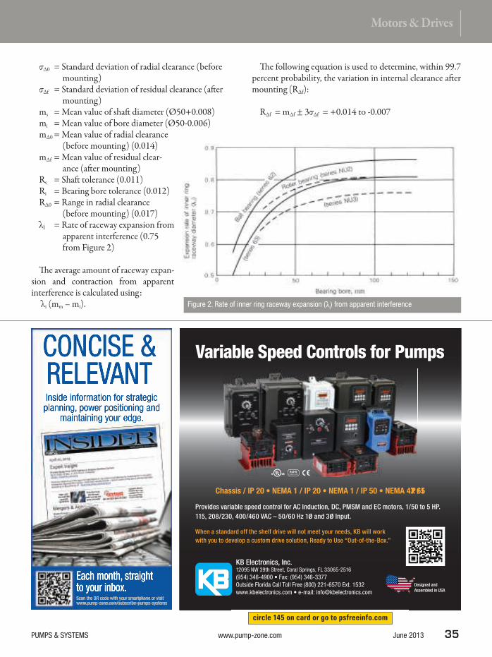
σΔ0 = Standard deviation of radial clearance (before mounting)
σΔf = Standard deviation of residual clearance (at er mounting)
ms = Mean value of shat diameter (Ø50+0.008) mi = Mean value of bore diameter (Ø50-0.006) mΔ0 = Mean value of radial clearance
(before mounting) (0.014) mΔf = Mean value of residual clear-
ance (at er mounting) Rs = Shat tolerance (0.011) Ri = Bearing bore tolerance (0.012)RΔ0 = Range in radial clearance
(before mounting) (0.017)λI = Rate of raceway expansion from
apparent interference (0.75 from Figure 2)
h e average amount of raceway expan-sion and contraction from apparent interference is calculated using:
λi (mm – mi).
h e following equation is used to determine, within 99.7 percent probability, the variation in internal clearance at er mounting (RΔf):
RΔf = mΔf ± 3σΔf = +0.014 to -0.007
Figure 2. Rate of inner ring raceway expansion (λi) from apparent interference
circle 145 on card or go to psfreeinfo.com
Variable Speed Controls for Pumps
When a standard off the shelf drive will not meet your needs, KB will work
with you to develop a custom drive solution, Ready to Use “Out-of-the-Box.”
Provides variable speed control for AC Induction, DC, PMSM and EC motors, 1/50 to 5 HP.
115, 208/230, 400/460 VAC – 50/60 Hz 1ø and 3ø Input.
KB Electronics, Inc.12095 NW 39th Street, Coral Springs, FL 33065-2516
Designed and
Assembled in USA

36 June 2013 www.pump-zone.com PUMPS & SYSTEMS
COVER
SERIES
In other words, the mean value of residual clearance—(mΔf) is +0.0035—and the range are from -0.007 to 0.014 for a 6310 bearing.
RADIAL INTERNAL CLEARANCE AND TEMPERATURE
When a bearing runs under a load, the temperature of the entire bearing will rise. h is includes the rolling elements. However, because this change is extremely dii cult to measure or estimate, the temperature of the rolling elements is gener-ally assumed to be the same as the inner-ring temperature.
Using a 6310 bearing again as an example, the reduc-tion in clearance caused by a temperature dif erence of 5 C between the inner and outer rings can be calculated using the following equation:
≈ 6 x 10⁻³(mm)
Where:δτ = Decrease in radial internal clearance caused by
a temperature dif erence between the inner and outer rings (mm)
α = Linear thermal expansion coei cient for bearing steel, 12.5 x 10⁻⁶ (1/ C)
Δt = Dif erence in temperature between inner ring (or rolling elements) and outer ring (C)
D = Outside diameter (6310 bearing, 110 mm) d = Bore diameter (6310 bearing, 50 mm) De = Outer-ring raceway diameter (mm)
h e following equations are used to calculate the outer-ring raceway diameter:
Using the values calculated for Δf and δt, the ef ective internal clearance (Δ) can be determined using the follow-ing equation:
D = Df – dt = (+0.014 to -0.007) – 0.006 = +0.008 to -0.013
In Figure 3, note how the ef ective internal clearance inl uences bearing life, in this example, with a radial load of 3,350 Newtons (or approximately 5 percent of the basic load rating). h e longest bearing life occurs under con-ditions in which the ef ective internal clearance is -13 micrometers. h e lowest limit to the preferred ef ective internal clearance range is also -13 micrometers.
APPLICATION
In theory, targeting a slightly nega-tive clearance is optimal for bearing life. However, in practice, end users must be careful when designing or building a pump with bearing pre-load. As shown in Figure 3, the life ratio peaks at -13 micrometers, but decreases dramatically with addi-tional preload. Incorrect assump-tions regarding machining tolerances or operating temperatures can easily result in a shorter life than anticipated if the bearing becomes preloaded too heavily.
αΔt (4D + d)5
δt = αΔtDe ≈
4D + d5
Ball bearings: De =
3D + d4
Roller bearings: De =
12.5 x 10-6 x 5 x (4 x 110 + 50)5
≈
circle 148 on card or go to psfreeinfo.com
ENGINEERED TO WORK
(800) 984-9400 | vogelsangusa.com | [email protected]
SLUDGE PUMPING SLUDGE GRINDING SLUDGE LYSING
and switch to a new Vogelsang Rotary Lobe Pump...
1. Space Savings - up to 50% smaller footprint.
2. Run Dry - never worry about damage again!
3. Easy Maintenance - work is done in place without manhandling heavy rotors and removing connected piping.
4. Less Downtime - maintenance and common problems can be fixed by one person in about an hour.
5. Lower Operating Cost - a new Vogelsang rotary lobe pump can typically be installed for the same amount as the parts and labor cost of a PC Pump repair.
5 reasonsto trash your PC Pump
obe Pump...
int.
ain!
e without g
mon
mp

Baldor Dodge® Disc couplings
offer industry leading torque
capacity and misalignment
capability for longer life and
improved reliability. With high
torque speed, misalignment,
and maintenance-free features,
Baldor Dodge Disc couplings meet
API 610 specifications for pumping
and compressor applications used
in the oil and gas industry. Count
on Baldor Dodge for all your disc
coupling needs.
And, you can find Baldor Dodge
disc couplings at your local Motion
Industries location. Our local sales
and service specialists are experts
in application and technical
support, providing the parts and
the know-how you need to stay up
and running.
The brands you count on from
the people you trust…that’s
Baldor Dodge and Motion
Industries.
Over 500 locations More than 4 million products
Industrial maintenance training courses Call. Click. Visit.
©2013 Motion Industries, Inc.
1-800-526-9328 for the location nearest you
MotionIndustries.com
circle 105 on card or go to psfreeinfo.com

38 June 2013 www.pump-zone.com PUMPS & SYSTEMS
COVER
SERIES
On the other hand, too much clearance can result in the bearing slipping and poor pump performance. End users must evaluate the trade-of s of clearance and bearing pre-load based on the needs of the application. Understanding the importance of bearing internal clearance will help increase bearing life and optimize overall pump perfor-mance. P&S
NSK Application Engineer Miles Woodard is a quali-
i ed Chief Engineer Ofi cer in the U.S. Navy and has
worked extensively with pump and compressor manu-
facturers for the past seven years.
As the segment manager for the pump and compres-
sor market, Ryan Thomas’ extensive knowledge and
expertise includes more than a decade of experience in the motion
control industry.
Thomas and Woodard are members of NSK’s North
American Pump & Compressor team, which addresses
the needs of the pump industry with engineering sup-
port, application analysis and innovative new product
development. For more information, visit www.nsk.
com/industries/pumpscompressors.html or contact
NSK at [email protected] 3. Relationship between the effective clearance and the bearing
life for a 6310 ball bearing
e in the motion

You do not need a special motor for severe duty. Severe Duty is standard with WEG W22 motors.
High performance with maximum energy efficiency is the goal of the WEG
W22 electric motor. High efficiency and low cost of ownership throughout
the entire motor lifetime have been the basis for the W22 development.
A design created to maximize performance and energy savings. Optimized
cooling system, large and accessible terminal box, exclusive bearing seal
system, low vibration levels, and a 1.25 service factor are just a few of
many STANDARD features of our W22 motors.
Available in NEMA Premium or Super Premium Efficiency levels.
Severe Duty is
Standard with WEG
W22 motors.
s.
emium Efficiency levels.
Motors | Automation | Energy | Transmission & Distribution | Coatings
© 2013 WEG Electric Corp.Transforming Energy into Solutions
To learn more about the W22 features and benefits or
to locate a WEG Distributor near you, please contact
1-800-ASK-4WEG or visit www.weg.net/us
circle 114 on card or go to psfreeinfo.com

40 June 2013 www.pump-zone.com PUMPS & SYSTEMS
COVERSERIES
Variable frequency drives (VFDs) are typically added to a system for economic reasons. While the realized
economic benei ts may be drastic throughout the life of the motor, several factors must be addressed to ensure the motor’s long-term reliability.
NON-INVERTER DUTY MOTORS
h e use of a VFD adds several areas of stress that non-inverter duty motors are unable to cope with long term. h e most common type VFD is pulse width modulated (PWM). A PWM drive uses short bursts of electricity to simulate a sine wave. h is approximation of the sine wave adds several types of stresses to the controlled motor. Shat grounding rings, insulated bearings and line i lters are some of the most common ways customers protect their motor investment from negative VFD attributes.
SYSTEM EFFICIENCY
While VFDs are not 100 percent ei cient, they do make economic sense when the operating speed of a motor needs to be lower than its rated speed. h erefore, choosing the correct motor for the application becomes crucial because motor ei ciency drops as speed and load decrease. VFD ei ciency also declines with motor speed, so it too needs to be correctly sized to the application. h e motor and drive ei ciencies combine to form part of the system ei ciency. h e system’s ei ciency is the product of: • VFD’s effi ciency• Motor’s effi ciency (average motor
effi ciency when operated on a VFD is reduced by one NEMA band versus sine wave operation)
• Driven equipment’s effi ciency (for example, pumps and fans)
MOTOR PROTECTION
When VFDs are used, steps must be taken to protect the motor and ensure ei cient system operation. h ese steps are discussed in this section.
Motor Speed
VFDs are used to run motors at speeds other than their nameplated speed. When a motor is subjected to a constant torque load, slower speeds may require an additional cool-ing method to avoid degrading the motor’s electrical insula-tion. However, if the load is a variable torque load, motor cooling is usually a non-issue when running at slower speeds.
Resonant Frequency
Another problem that typically arises is the resonant fre-quency of the system. If a motor is run at the system’s reso-nant frequency, many components of the system can be damaged because of excessive vibration. However, once this frequency is known, the VFD can be programmed to skip the resonant area during operation.
Switching Frequency
h e switching frequency of a drive is another area for con-cern. When the frequency is too fast, voltage overshoot will occur. h is overshoot is a result of the capacitance of the motor charging and discharging at a rate that is dif erent from the drive. h is large voltage spike experienced by the motor in a short time period can cause an uneven distribu-tion of voltage in the windings. When a motor is repeat-edly exposed to overshoot, it is normally seen in the i rst few turns of the windings at er failure.
Long-Term Motor ReliabilityA variable frequency drive’s effect on system efi ciency and motor life
By Timothy Albers and Steve Hauck, Nidec Motor Corporation
A
B
Figure 1. Flow rates at different motor speeds

PUMPS & SYSTEMS www.pump-zone.com June 2013 41
Motors & Drives
Connections
h e cables between the VFD and motor should also be con-sidered. When a mismatch in impedances happens, rel ec-tions occur in the lines that add with the nominal voltage signal sent to the motor. h is phenomenon can be intensi-i ed by the switching frequency of the drive.
Startup
Several downsides exist when starting an induction motor on full line volt-age. Large magnetic i elds are created that lead to movement in the motor’s windings while large inrush currents cause rapid heating. h e movement of the windings can eventually lead to abraded insulation and shorted con-ductors. h e rapid heating becomes an issue because the windings expand faster than the stator core, leading to eventual insulation damage. VFDs reduce this extreme mechanical stress by ramping up the frequency and voltage to bring the motor to operat-ing speed, which lowers the motor’s inrush current.
High-Frequency Voltage
A common issue seen with VFD usage is an induced, high-frequency voltage in the motor’s rotor assembly. h ese voltages, typically referred to in the industry as shat currents, wreak havoc on bearings. Once the bearing’s lubrication insulation breaks down, the voltage has a path to ground, which results in premature failure.
One way to combat this issue is using insulated bearings. Insulated bearings work just as the name implies. h ey are insulated from the motor with a non-conductive mate-rial that removes the ground path for the damaging currents.
If the motor is coupled to any other devices (such as pumps and gearboxes), the shat currents can discharge through their bearings. A preventive measure in that scenario
would be a shat grounding ring. A shat grounding ring is normally attached to the motor and uses carbon brushes that contact the rotating shat of the motor. h e brushes provide a path for the shat currents to dissipate through while protecting all the equipment within the system.
800.603.7867 951.342.3100 www.BLACOH.com [email protected]
Specifically designed for hygienic applications requiring clean-in-
place components, our inline flow through design and unique patent
pending tube bladder eliminate problems with product holdup and
trapped particles. Ideally suited for handling slurries and viscous
fluids, it’s gentle enough for the most delicate products.
316L polished stainless steel self-draining single body
construction for easy clean-in-place
USP Class VI pharma-grade silicone bladder connects directly
to piping with Tri-Clamp fasteners
THE CLEAN ALTERNATIVE
FOR PULSATION AND
SURGE CONTROL.
FLOW THROUGH PULSATION DAMPENER
circle 139 on card or go to psfreeinfo.com

42 June 2013 www.pump-zone.com PUMPS & SYSTEMS
COVER
SERIES
Harmonics, Surge & Power Factor
Line i lters or terminators are another component used to reduce harmonics and surge voltages, correct power factor, and improve the overall power quality delivered to the motor.
Line i lters greatly reduce rel ections and voltage spikes that lead to winding failure. h ey also mitigate common mode voltages that drive shat currents.
SAMPLE SYSTEMS
Looking at the hypothetical graph in Figure 1, a l ow rate of approx-imately 125 gallons per minute (gpm) is obtainable at Points A or B. Point A is the pump l ow at normal motor speed, and Point B marks the l ow at a reduced motor speed. Using a lower pump speed reduces the current draw and load placed on the pumping compo-nents while delivering the same l ow as the higher pressure setting.
Suppose an end user has a 20-horsepower motor running the pump used in Figure 1. Assume that the pump runs at a full speed 75 percent of the time and is operating at 85 percent of its rated speed the remaining 25 per-cent of the time. In this case (see Table 1), the VFD is not being optimized for best economic impact.
Now, assume that the same motor is operating at 90 percent of rated speed for 75 percent of its operation time and at 75 percent of rated speed the remaining time (see Table 2). In this example, a $671.64 energy savings is achieved.
If the example shown in Table 2 is applied to a 50-horsepower motor, the energy savings is even more pronounced (see Table 3). h e bottom line is that VFDs of er cost savings to the user when prop-erly i tted to an application. P&S
Steve Hauck is a design engineer in the New
Product Development group for Nidec Motor
Corporation’s Industrial Motors Division/U.S.
Motors. Hauck received his undergraduate degree
in electrical engineering from the University of
Missouri St. Louis—Washington University joint
undergraduate engineering program. His current
responsibilities include the development of both
small and large motor designs. Hauck can be
reached at [email protected].
Timothy Albers is the director of product man-
agement and OEM marketing for Nidec Motor
Corporation’s Industrial Motor Division/U.S.
Motors. His current responsibilities include prod-
uct management, marketing and quotation support
for the Industrial Motor Division. Albers has held
positions in marketing for Nidec Motor Corporation
and Emerson Motor Company, including product-
line manager for NEMA motors. His past experi-
ence includes marketing and product development at U.S. Motors/Emerson and
marketing and sales in electric motors and drives at General Electric and as a
qualii ed U.S. Navy operating engineering ofi cer.
Table 1. A pump operating at full speed 75 percent of the time
and at 85 percent of rated speed the remaining 25 percent
Table 2. A pump operating at 90 percent of rated speed for 75 percent of the
time and at 75 percent of rated speed for the remaining 25 percent
Table 3. Data from a pump operating with a 50-horsepower motor

NOTHING GOODHAPPENS AFTERMIDNIGHT
Nobody wants that middle-of-the-night-call telling you systems are down. Not you. Not us. And, certainly not the guy with the problem. That’s one of the reasons you should turn to Yaskawa for drives and motion control.
Trust your operations to Yaskawa and the phone won’t ring at night. The boss won’t be in your offi ce. And, maintenance won’t be breathing down your neck with another fi re to put out. Trust Yaskawa and you’ll get a good night’s sleep.
Rest easy tonight. Call Yaskawa today.
YA S K AWA A M E R I C A , I N C .
D R I V E S & M O T I O N D I V I S I O N
1 - 8 0 0 -YA S K AWA YA S K AWA . C O M
Follow us: For more info:http://Ez.com/yai473
©2013 Yaskawa America Inc.circle 116 on card or go to psfreeinfo.com

44 June 2013 www.pump-zone.com PUMPS & SYSTEMS
COVER
SERIES
A series of studies by the Institute of Electrical and Electronics Engineers, Inc. (IEEE) and the Electric
Power Research Institute (EPRI) from 1983 until 19951,
2, 3 that covered all industries reported that bearing faults, followed by winding faults, were prevalent (see Figure 1). h ese studies, one performed by Advanced Energy4 and another performed by the Electrical Apparatus Service Association (EASA)5 also revealed that repaired motors, in many cases, do not last as long as they should because of poor repair practices. h e repetitive failures of these motors may have resulted, in part, because of a lack of diagnostics or forensics reported to the motor owner during the repair process.
REPAIR AND COMMUNICATION
While many studies and surveys performed through 2013 identify that a good repair will last longer, few have iden-tii ed the importance of providing the motor owner with feedback on the possible root causes of the failures. How does the owner’s maintenance department or the reliabil-ity engineers respond to a report of replaced bearings or a rewound stator? Do they respond in a way that prevents the problem from recurring?
A signii cant dif erence between the 2003 and 2013 Motor Diagnostics and Motor Health Studies (MDMH)6
was that in 2003, 56 percent of organizations reported
electricians as the person responsible for electric motors, and only 2 percent were reliability engineers. In 2013, the number shit ed to 43 percent reliability engineers and 26 percent electricians with a signii cant decrease in mechani-cal and general maintenance personnel. By dei nition, a reliability engineer requires feedback to pursue his trade, meaning that an understanding of the equipment failure—including potential root causes and corrective recommen-dations—becomes more critical in the repair process.
For instance, if the motor failed because the bearings were noisy, what caused them to become noisy? Were they over or under greased? Was the belt experiencing over-tension or misalignment? Was there bearing l uting because of shat currents? h is information, including recommendations, will assist the motor owner or reliability engineer in devel-oping a plan to mitigate future problems.
For example, the bearings in a motor that is operated by VFD are l uted (see Image 1). h is l uting is an indicator of shat currents. Corrective action using a shat brush or a shat brush and insulated bearing should be taken. h is also means that either the repair facility’s representative should be asking application questions, and/or the motor owner should be providing that application information.
Rewind related failure modes must also be identii ed. If the winding has been single phased and that informa-tion is not communicated, the failure will likely reoccur.
Electric Motor Repair & ReliabilityRepetitive motor failures may be caused by a lack of diagnostic or forensic repair information reported to the motor owner.
By Howard W. Penrose, Dreisilker Electric Motors, Inc.
Figure 1. Comparison of three motor reliability studiesImage 1. Bearing fl uting caused by shaft currents

PUMPS & SYSTEMS www.pump-zone.com June 2013 45
Motors & Drives
Identifying that the failure occurred would be important, in this instance, because an electronic overload with sin-gle-phase protection would mitigate similar failures in the future. If, on the other hand, the winding failed because it was overloaded, the reliability engineer should recommend that the overload protection is also evaluated.
REPAIR’S IMPACT ON RELIABILITY
As noted by the U.S. Department of Energy, “Of the quality assurance procedures shops used, 40 percent were repair procedure specii cations, 25 percent were test specii cations, and 21 percent were EASA standards. Only one of the 65 shops surveyed used any form of quality assurance testing.”7
In fact, per the same report, almost half the shops surveyed performed no winding tests during the entire repair. Of the repair shops, 81 percent also reported that they changed wind-ing coni guration in electric motors during the repair process primarily for shop preference or ease of wind-ing (73 percent), 10 percent with the owners’ knowledge and only 4 percent for the purpose of reliability or durability. h e remainder did not provide a reason.
Proper repair practices are vital to
the reliability of the repaired electric motor. While the stud-ies primarily focus on energy consumption or ei ciency of the machines, the 2013 MDMH identii ed a solid 0 percent of interest in energy as a driver for a motor program (only 3 percent in 2003). h e key driver for the motor program was reliability (75.5 percent).
Image 2. Overloaded windingcircle 138 on card or go to psfreeinfo.com

46 June 2013 www.pump-zone.com PUMPS & SYSTEMS
COVER
SERIES
Following the reliability perspective and study results, the only reason for modii cations from the original manufac-turer’s design must be for improvements to the durability of the machine or engineering modii cations to improve the reliability of the application. Modii cations to make the repair less expensive or because the repair shop does not maintain the appropriate metric or half-size wire does not benei t the end user and can become expensive in the short term and extremely expensive in the long term. Companies that peen or glue bearing i ts should be strenuously avoided. Such repairs should only ever be considered to get by while awaiting a replacement with the knowledge that the risk of catastrophic failure is high.
Properly maintaining i ts through testing and machining
to tolerance using welding, sleeving or remanufacturing will maintain potential bearing life and decrease friction and windage losses. While these losses relate to energy consump-tion, they also result in increased operating temperature. Just as with winding insulation life, for every 10 C increase in bearing temperature, the grease life reduces by half.
In 1984, David C. Montgomery published a paper that identii ed the impacts of core loss increases of 50 percent, 100 percent, 150 percent and 200 percent and related it to temperature rise, resulting insulation life and impact on grease/bearing life based on winding removal processes using high temperatures.8 h e machine used in the example was a 50-horsepower, 3,600-rpm, drip-proof motor. He also related that the core loss impact is greater as the motor size
increases.h e burnout oven stripping issue of electric
motors has been a long-standing one. h e use of high-temperature stripping results in a limit to the number of times a winding can be rewound, an impact on the mechanical i ts and sot foot, an increase in associated greenhouse gas emissions because of drops in ei ciency and community
health issues.9 h e use of repair pro-cesses that involve high-temperature stripping must be carefully considered because it may impact overall system reliability.
While the close monitoring of ther-mal stripping methods is strongly recommended based on the studies, professional societies and trade associ-ations, the number of cores damaged from excessive temperatures is on the rise. If an end user has a motor that has an increase in operating current, then the core is probably damaged. Just the change of an amp of current can cause a signii cant increase in core losses and excessive shims required for align-ment, related to frame distortion. Mechanical and induction processes using low temperatures are available that have no negative impact on core losses.10
Testing throughout the repair pro-cess is critical and must be recorded. h e repairs must also be performed with calibrated equipment. Testing must include:
% Core Loss
Increase
Watts/lb
Increase
Temperature
Rise Increase
% Potential
Insulation Life
Approximate %
Grease Life
50 515 7 C 62 85
100 1,030 14 C 38 69
150 1,545 21 C 24 58
200 2,060 29 C 14 46
Table 1. Impact of core losses because of burnout ovens
circle 141 on card or go to psfreeinfo.com

circle 106 on card or go to psfreeinfo.com

48 June 2013 www.pump-zone.com PUMPS & SYSTEMS
COVERSERIES
• Phase resistance• Insulation resistance• High potential testing• Surge testing• Rotor testing• Core loss testing• Other tests depending on the type of electric motor
Mechanical tests must be performed with calibrated mea-suring instruments. Running tests should include voltage, current, vibration and audible tests.
With the low cost of digital memory, digital photos of the motor should be taken when it is received by the repair shop and prior to shipping, at a minimum. Unusual faults should be photographed and provided in a i nal report along with any data required by the reliability engineers, as appropriate. It is also recommended that forensic analysis and root-cause failure analysis be performed with input by the end user and repair facility when critical machines fail or if repeat failures occur.
INSTALLATION CONSIDERATIONS
Some end users ask, “Why should I have a Cadillac repair when I have Yugo mechanics?” Meaning, what is the point of having a reliable repair when the machine is going to be misaligned, miss-tensioned or have other issues? One simple answer, which is not even buried in reliability or industrial engineering, should be given: two unreliable systems create an even more unreliable system.
A combination of poor reliable installation with reliable repairs will increase the reliability of the system. In ef ect, a highly robust repair can result in a system that is better able to withstand poorly applied or installed motors.
CASE STUDY
A low-quality repair has a poor bearing installation and a damaged core. Instead of a motor that would last 10 years (120 months), the end user has a motor that lasts about six months. When applied to the reliability formula (Equation 1), the result is a reliability of 0.905 (90.5 percent chance of surviving the i rst year) for a reliable repair example and 0.05 (5 percent) for the low-quality repaired motor.
R = e-tλ (Equation 1)Where:λ = 1/Mean time between failure (MTBF) t = Time in months
A maintenance technician has a success rate of improper installation, resulting in an average life expectancy of a motor installation being about one year because of issues such as loose connections, improper belt tension or align-ment. His reliability would be 0.368 (36.8 percent).
When this technician is paired with the low reliability repair, the result is (0.05 * 0.368 = R) 0.0184, or a 2 percent chance that the motor will survive the i rst year. If, however, a high reliability repair is used, then the result is (0.905 * 0.368 = R) 0.333, or a 33.3 percent chance that the motor will survive the i rst year.
While an organization’s improvement of installation and maintenance is important, a higher quality repair is even more critical in an evolving maintenance department. When considering that the average cost per hour of down-time is $10,000 for critical machines (from both the 2003 and 2013 MDMH studies), the improvement in repair sav-ings can be staggering. P&S
References
1. Albrecht, Appiarius, McCoy, Owen and Sharma, “Assessment of the Reliability of Motors in Utility Applications – Updated,” IEEE Transactions on Energy Conversion, Vol. EC-1, No. 1, March, 1986.
2. Motor Reliability Working Group, “Report of Large Motor Reliability Survey of Industrial and Commercial Installations, Part 1,” IEEE Transactions on Industry Applications, Vol. 1A-21, No. 4, July/August, 1985.
3. h orson and Dalva, “A Survey of Faults on Induction Motors in Of shore Oil Industry, Petrochemical Industry, Gas Terminals, and Oil Rei neries,” IEEE Transactions on Industry Applications, Vol. 31, No. 5, September/October, 1995.
4. Advanced Energy, Achieving More with Less: Ei ciency and Economics of Motor Decision Tools, Advanced Energy, USA, 2006.
5. EASA/AEMT, h e Ef ect of Repair/Rewinding on Motor Ei ciency, Electrical Apparatus Service Association, Inc. and Association of Electrical and Mechanical Trades, Inc., USA and UK, 2003.
6. Penrose, Howard W., 2013 Motor Diagnostics and Motor Health Study, motordiagnostics.com, April, 2013.
7. Schueler, Leistner and Douglass, Industrial Motor Repair in the United States, Bonneville Power Administration, USA, 1995.
8. Montgomery, David, “h e Motor Rewind Issue – A New Look,” IEEE Transactions on Industry Applications, Vol 1A-20, No. 5, September/October 1984.
9. Penrose, Howard W. and Dreisilker, Leo F., “h e Mechanical Ef ects from h ermal Stripping Induction Motor Stators,” 1997 EIC/EMCWA Conference Proceedings, IEEE, 1997.
10. Penrose, Howard W. and Dreisilker, Leo F., “Evaluation of Induction Warming Stator Cores for Coil Removal,” Conference Record of the 2012 International Symposium on Electrical Insulation, IEEE, 2012.
Howard W. Penrose, Ph.D., CMRP, is the vice president
of Engineering and Reliability Services for Dreisilker
Electric Motors, Inc.; the webmaster for the IEEE
Dielectrics and Electrical Insulation Society; and the
outreach director for the Society for Maintenance and
Reliability Professionals, Inc. He can be contacted at

Toshiba International Corporation is proud to be a single-source
solution for your pump application demands, offering a complete
product lineup of low and medium voltage electric motors.
Efficiency, Quality, & Performance (EQP)The Toshiba EQP Global® low voltage motor product line is
designed to perform beyond the competitive demands of severe
duty pumping applications. Building on over 20 years of success
with our EQPIII motor series, the EQP Global line features multiple
new design enhancements that make it one of the lowest cost-of-
ownership products in the industry.
Introducing the Toshiba VTXThe Toshiba VTX Vertical Hollow Shaft medium voltage motor is
Toshiba’s latest innovation for the pumping industry. Featuring
a self-cooled thrust bearing that uses proven thermal siphon
technology, the VTX is built to withstand even the toughest upstream
geothermal pumping applications.
VTX Vertical
Hollow Shaft MotorEQP Global® Motor
O N E C A L L . O N E S O L U T I O N .
1-800-231-1412
toshiba.com/motors
Visit us at EASA Booth #615!
EASA 2013LAS VEGAS
JUNE 30 – JULY 2
Toshiba would like to thank our distribution
network, pump OEMs, and end-users for
your unwavering support as we continue
to experience unprecedented growth and
associated challenges.
circle 117 on card or go to psfreeinfo.com

50 June 2013 www.pump-zone.com PUMPS & SYSTEMS
COVER
SERIES
According to the Department of Energy, motor-driven equipment—such as pumps, fans and compressors—
consume about 16 percent of the energy used in U.S. industrial applications, amounting to $30 billion spent annually. For variable torque applications, installing a variable frequency drive (VFD) with the latest motor control technology is a simple and cost-ef ective way to achieve signii cant energy savings. Whether moving air or water, or controlling production speed, the ability to match the speed of the motor or pump to the desired output can reduce energy consump-tion and save on costs and resources.
Energy and the associated cost savings are the main motives for using VFDs. When a drive is applied to a fan or pump, the return on investment can be realized in as few as three to four months.
VFDs are designed to provide variable speed con-trol. h ey maintain the optimal speed required for an application to enhance pro-duction and save energy. Low- and medium-voltage drives gradually accelerate and decelerate motors and pumps, helping protect mechanical components and extend their life, while reducing inrush currents, which helps save energy. VFDs are used in a broad range of industries and applications—including HVAC, water and wastewater, and oil and gas.
HISTORY OF VFDS
AC induction motors were developed in the late 1800s, using polyphase electrical current to develop a rotating magnetic i eld. h e rotor of the alternating current (AC) induction motor follows the rotating magnetic i eld and
can connect to rotating equipment such as pumps, fans and machinery. h e limitation of the induction motor is that it can only rotate at a speed comparable to the frequency of the AC power provided.
h e AC VFD signii cantly changed the way that AC induction motors could be used by providing an ei cient, electronic way to vary the frequency of the supply current, which then varied the speed of the motor. Early on, VFDs were used in process control for manufacturing synthetic
VFDs Save Energy in Pump ApplicationsUsing variable frequency drives provides many benei ts to end users.
By Tom Neuberger, Eaton
Graph A Graph B
Flow orVolume (%)
Pressure orHead (%)
Speed (%) Speed (%)
Flow1
Flow2
RPM1
RPM2
=Head
1
Head2
RPM1
RPM2
=
2
Graph C
Power or EnergyConsumption (%)
Speed (%)
Power1
Power2
RPM1
RPM2
=
3
Figure 1. The affi nity laws
1. Flow / volume varies linearly with speed. (Graph A)
2. Pressure / head varies as a square of the speed. (Graph B)
3. Power or energy consumption varies as a cube of the speed. (Graph C)
He
ad
or
Pre
ssu
re (
ft)
Flow Rate (gpm)
System Curve
FrictionHead
180
160
140
120
100
80
60
40
20
00 40 80 120 160 200
Static Head or Lift
Figure 2. Elements of a system curve

PUMPS & SYSTEMS www.pump-zone.com June 2013 51
Motors & Drives
i ber, steel bars and aluminum foil. VFDs improved process performance and reduced maintenance costs. As a result, they were used to replace motor generator sets and direct current (DC) drives.
Later, during the 1970s energy crisis, saving energy was crucial. VFDs were increasingly tapped to help reduce energy consumption in large pump applications and eventually in HVAC fan systems.
VFDs are a critical component of motor speed control. h ey improve ei ciency, reduce wear on mechani-cal components and improve system performance. Fundamentally, they are used to control the frequency and voltage supply to the motor and match the application’s speed requirements.
THE AFFINITY LAWS
h e ai nity laws can determine the system performance for centrifu-gal devices, dei ning both theoreti-cal load requirements and possible energy savings. h e three ai nity laws are shown in Figure 1.
Determining the system curve (see Figure 2) is important to select the proper system pump. h is curve describes what l ow will occur given a specii c pressure. Static head or lit and friction head need to be dei ned. Static head/lit is the height that the l uid must be lit ed from the source to the outlet. Friction head is the power required to overcome losses caused by the l ow of l uid in the piping, valves, bends and other devices in the system. h ese losses are l ow-depen-dent and are nonlinear.
In Figure 2, the system curve and pump performance curve intersect at the desired operating point of 120 feet of pressure and 160 gallons per minute of l ow. h e system will have a single operating point unless a device is added, and a pumping application rarely requires the pump to produce maximum l ow.
VFDS VERSUS THROTTLING DEVICES
A mechanical throttling device is ot en used to limit l ow. h is is an ef ective control method. However, it wastes both mechanical and electrical energy. Energy use with a throt-tling device is shown in Figure 5. h e lower curve shows energy use with a VFD. Since VFDs adjust the frequency
For over 50 years - Two trusted names in the
electric motor and pump repair industry.
Visit us on the web at wwww.bartlettbearing.com
and
800-523-3382
circle 121 on card or go to psfreeinfo.com

52 June 2013 www.pump-zone.com PUMPS & SYSTEMS
COVER
SERIES
of an AC motor, l ow and energy consumption are reduced. h e green shaded area shows the energy saved.
A throttling device is typically used as a mechanical way to reduce the l ow rate in a pumping system. Applying a throttling device to the system changes the system curve (see Figure 3). h e throttling device reduces the l ow of the system, yet the pump curve is not changed. h is wastes energy and creates mechanical stress. Since the pump oper-ates at full speed, a tremendous amount of energy is used. Also, mechanical stresses on the pump system can prema-turely result in seal or bearing failures.
THE ADDITION OF VFDS
VFDs electronically control power supplied to the motor, closely matching power requirements to produce a speci-i ed l ow. h is is similar to using a new pump with a smaller impeller.
To see the energy savings with VFD technology, Figure 7 combines Figure 4 and Figure 6. h e blue shaded area demonstrates the resulting energy savings realized by using a VFD instead of a throttling device.
By using VFDs, additional cost savings can be realized because fewer components are needed for valve control. With a throttling control system, losses occur in the valve, and additional piping is needed to bring the valve to a height at which it can be adjusted.
Because of these losses and the internal pump loss, to obtain a head equivalent to 50 horsepower, an equivalent of a 90 horsepower pump and a 100 horsepower motor is required. With a VFD, no valve or pipe losses occur because of bends or additional piping, reducing the piping losses to 8 horsepower. With the reduction of these losses, a smaller pump can be used with lower losses. For the same equivalent of 50 horsepower of head, only a 68 horsepower pump and a 75 horsepower motor are required. h is results in a sub-stantial system cost and installation savings, economically justifying the VFD.
ENERGY SAVINGS & EXTENDED EQUIPMENT LIFE
By matching power consumption to changing system requirements, VFDs are relied upon to provide steady, ei -cient power for variable speed pump applications. VFDs protect motor and pump assets by controlling power and minimizing the mechanical stress caused by starting and stopping the pumps.
h e latest generation of VFDs is more ei cient, accurate and rei ned—leading to increased energy savings. New and sophisticated technologies are impacting ei ciency.
kW Meter
kW Meter
Valve
VFD
System Curve(Throttling Device)
He
ad
or
Pre
ssu
re (
ft)
Flow Rate (gpm)
180
160
140
120
100
80
60
40
20
00 40 80 120 160 200
Pump Performance Curveat Full Speed
Required hpat Full Speed
Figure 3. A pumping system using a mechanical throttling valve and
the same system using a VFD
Figure 4. System characteristics using a mechanical throttling device.
The energy consumed is represented by the blue shaded area.
Figure 5. The amount of energy saved by using a variable frequency
drive versus a valve to control fl ow
Po
wer
Co
nsu
mp
tio
n (
%)
VFD
Flow (%)
Throttling Device
EnergySavings
100
80
60
40
20
0
0 20 40 60 80 100

PUMPS & SYSTEMS www.pump-zone.com June 2013 53
Motors & Drives
Specii cally, advancements in capacitors and DC link reac-tors, insulated-gate bipolar transistors, heat management, processing power and measuring technology enable the development of solutions to problems that were not recog-nized earlier. Additionally, new and advanced algorithms af ect energy ei ciency. P&S
Tom Neuberger is a product manager at Eaton in
Menomonee Falls, Wis. For additional information, he
can be reached at [email protected].
System Curve
Head
or
Pre
ssu
re (
ft)
Flow Rate (gpm)
180
160
140
120
100
80
60
40
20
00 40 80 120 160 200
Pump Performance Curveat Reduced Speed (VFD)
Required hp at Reduced Speed
System Curve
Head
or
Pre
ssu
re (
ft)
Flow Rate (gpm)
180
160
140
120
100
80
60
40
20
00 40 80 120 160 200
Pump Performance Curveat Full Speed
Required hp at Full Speed
Required hp at Reduced Speed
Pump Performance Curveat Reduced Speed (VFD)
System Curve(ThrottlingDevice)
Figure 6. The pump curve and the energy used with VFD control; note
that the pressure is also reduced, helping reduce the mechanical
stresses that are created with throttling devices.Figure 7. The resulting energy saved by replacing a throttling device
with a VFD
circle 153 on card or go to psfreeinfo.com circle 154 on card or go to psfreeinfo.com

54 June 2013 www.pump-zone.com PUMPS & SYSTEMS
COVER
SERIES
The Electrical Apparatus Service Association, Inc., (EASA) is an international trade organization of more
than 1,900 electromechanical sales and service i rms in 59 countries. h e EASA Convention is an annual event for electrical industry professionals. h is year, the three-day event will be held in Las Vegas, Nev. EASA provides an opportunity for manufacturers and end users of motors and drives to network. Attendees have access to technical sessions and opportunities for optional service center tours. Many electrical apparatus will also be on display during the event, and attendees will be informed about recent updates and changes in the industry.
h e event features educational sessions presented by industry professionals that provide an overview on failure analysis and information on restructuring sales organiza-tions. Last year, almost 550 service centers were repre-sented at the exhibition. Young researchers will also have the opportunity to share their research papers with inter-national industry professionals during the event. For more information, visit www.easa.com.
Exhibition Hours
Sunday, June 30 1 p.m. – 4:30 p.m.
Monday, July 1 Noon – 4 p.m.
Tuesday, July 2 9 a.m. – Noon
EASA ConventionJune 30 – July 2, 2013Mandalay Bay Resort and CasinoLas Vegas, Nev.
circle 142 on card or go to psfreeinfo.com
Wastewater
Power Generation
Refinery & Terminal
Food & Beverage
ww
w
.denm
arpump.com 199 Turnpike St. S
toughto
n M
A, 0
2072
DPSWh
ere R
elibility is Every
thin
g
Denmar Pump Services

Knowledge: As global leaders in
technology, suppling engineered
products & services to energy
services customers and other major
process industries, John Crane is
committed to continuous innovation
and investment in cutting edge
technology around the world.
Experience: John Crane is the
largest designer, manufacturer and
supplier of advanced sealing technology. Continuous research and unparalleled industry experience has created
the widest available range of EndtoEnd Solutions™. Significant investment programs ensure that increasing rotat-
ing equipment demands will continue to be satisfied well into the future.
Service: Around the world and around the corner; with a workforce of more than 7,000 people and 200+ facilities
in over 50 countries, John Crane is totally committed to customer service with investment in a vast network of
global customer support locations offering world class service 24/7. Which is why users around the world rely on
John Crane to minimize cost of ownership, guarantee reliability and maximize asset availability.
John Crane - Your choice for ENDtoEND Solutions
www.johncrane.com
For more details please contact John Crane
6400 West Oakton Street Morton Grove, IL 60053
Tel: 847.967.2400 Fax: 847.967.3915 Email: [email protected]
Want to find out more?
Scan this QR code with
your smartphone.
Mechanical Seals
Filtration Systems
Packing
Engineered Bearings
Couplings
Gas Seals
Support Systems
Production Solutions
TM
circle 118 on card or go to psfreeinfo.com

SPECIAL SECTION
56 June 2013 www.pump-zone.com PUMPS & SYSTEMS
Pump Repair & Maintenance
SPECIAL
SECTION
Severely eroded suction bowl
Photo courtesy of Hydro Inc.

Pump Repair & Maintenance
PUMPS & SYSTEMS www.pump-zone.com June 2013 57
The population of industrial pumps is aging. An article from Pumps & Systems’ August 2012 issue chronicled
the repair of an 82-year old pump still in service in a major rei nery. Like this rei nery, many industrial operations use pumps that have been in service 30 to 50 years or more.
h is article presents a case study of a recently refurbished vertical pump. h e case study demonstrates how the prob-lem of an unavailable, critical part was overcome through reverse engineering. It also shares the lessons learned and how to develop a strategy to overcome part shortages for old or obsolete pumping equipment.
CRITICAL PART SHORTAGE IDENTIFIED
A single-stage, vertical pump in a service water application was sent for repair by a nuclear power plant to a qualii ed, inde-pendent pump service and engineering provider. A thorough inspection was per-formed. Although several important parts had to be reverse engineered and manufac-tured, all but one were machined parts for which raw material was available. One large cast part, a large aluminum bronze suction bowl weighing more than 500 pounds, was identii ed as the critical delivery issue.
MODERN TECHNOLOGY APPLIED
h e independent service provider had a skilled, in-house engineering team that used process control procedures for reverse engineering under its Nuclear Procurement Issues Committee (NUPIC) audited qual-ity assurance program. h is service organi-zation understands that reverse engineering is not the same as replicating. h e service center’s engineering team evaluated the
critical characteristics of the component, which is an essen-tial step in developing a replacement part that will meet the same form, i t and function as the original.
h e engineers started the process by producing a 3-D model and a 2-D drawing of the suction bowl, capturing the part’s geometry with the aid of a state-of-the-art coordinate measurement machine (CMM).
h e portable CMM, with a seven-axis articulation and equipped with both contact and non-contact (laser) probes, enabled the engineers to quickly capture the dimensions of the suction bowl with high precision. To address the miss-ing geometry of the eroded vanes, an engineering analysis
Reverse Engineering of a Vertical Pump Suction Bowl The pump was returned to service at a nuclear power plant after reverse engineering of an unavailable part and complete pump testing.
By Jeff Smith, Hydro Parts Solutions Inc., & Dr. T. Ravisundar & Werner Barnard, HydroAire Inc.
Solidifi cation simulation
Image courtesy of Hydro Parts Solutions Inc., a Hydro Company

SPECIAL SECTION
58 June 2013 www.pump-zone.com PUMPS & SYSTEMS
was performed to reconstruct the original geometry. With this information, a 3-D model was created. In addition to measuring the geometry of the part, all the critical characteristics—such as hardness, chemical composition, surface i nish, i ts and toler-ances—were evaluated.
h e reverse engineered data of the bowl’s hydrau-lic passageways was then thoroughly reviewed. h is included vane-to-vane distance, vane curvature from the leading edge to the trailing edge, hub and shroud curvature, vane thickness distribution, and all other critical dimensions. h e hydraulic contours of the 3-D model were then smoothed without sig-nii cantly af ecting the original geometry, and the vane thickness distribution was made uniform. h e 3-D model developed for the casting was completed by adding machining allowances for bores, l ange outer diameters and faces.
Once the 3-D model for the casting was com-plete, the service provider’s engineers worked with a reliable foundry known for producing excellent alu-minum bronze castings to develop a manufacturing Typical sand-printed core
Image courtesy of Hydro Parts Solutions Inc., a Hydro Company
circle 152 on card or go to psfreeinfo.com circle 149 on card or go to psfreeinfo.com
Our Pump Systems Do What Other’s Can’tMaag gear pumps are engineered for some of the most demanding conditions to which a pump can be subjected:
pressures to 5,075 psitemperatures to 600 °Fviscosities to 4,000,000 cP
Clearances in four different pump areas are chosen for the particular application. Pumps can also be sup-plied stand-alone. Call to learn more.
Maag Automatik Inc.
Charlotte, NC
704-716-9000 TEL. 914.968.8400 • WWW.GRAPHALLOY.COM/PS
RUN DRY, ANDKEEP ON RUNNING.
GRAPHITE METALLIZINGCORPORATION
Yonkers, NY 10703 U.S.A.
ISO 9001:2008
Pumps fitted with GRAPHALLOY®
wear parts survive upsets.
PS09b
GRAPHALLOY® bushings
and case rings:
• Run hot, cold, wet or dry
• Reduce maintenance
• New pumps or retrofits
• Non-galling
• Self-lubricating• -400°F to 1,000°F
-240°C to 535°C+• Corrosion resistant

Pump Repair & Maintenance
PUMPS & SYSTEMS www.pump-zone.com June 2013 59
and quality plan to cast the replacement suction bowl. With a thorough understanding of the latest rapid cast-ing processes, the engineering team created a casting plan that included a layout for the risers, gates, runners, sprue and other mold package details. h is plan was engi-neered using solidii cation simulation sot ware so the engineers could determine the optimal layout for the mold package. A well-designed mold package reduced the risk of a failed casting and maintained the rebuild schedule.
Once the casting plan was complete, the 3-D model was used to make a large, sand-printed mold package. h e mold package consisted of several mold pieces and a large core for creating the intricate details within the bowl. h is modern technology allowed the service provider to produce a successful casting in a timely manner without a hard pattern or core box.
INSPECTION AND TESTING
h e cast suction bowl was sent to the service center for inspection by the quality assurance team. h e chemical and physical characteristics were analyzed and found to be within the American Society for Testing and Materials (ASTM) ranges. It was also observed that the casting’s surface i nish and dimensional accuracy was superior to that of conventional castings for the given material.
h e service center’s engineering team proceeded with a part compari-son to ensure equivalency. Using a CMM, a 3-D model was created with the cast part and overlaid onto the 3-D model of the reverse engineered suction bowl. In Figure 1, the yellow area shows the reverse engineered model. h e blue area shows the cast bowl model. h e overlapping surfaces of both models coni rm the confor-mance of the geometry of the cast bowl to the geometry of the reverse engineered bowl.
Any observed deviations from the geometry of the reverse engi-neered bowl were determined to be negligible and were far less than the deviations that typically occur in con-ventional castings. Furthermore, the
critical hydraulic dimensions on every vane passage were coni rmed to be correct and uniform to ensure hydraulic performance and operational stability.
h e suction bowl was i nish machined, and at er passing
Figure 1. Comparison of 3-D models
Image courtesy of Hydro Inc.
circle 143 on card or go to psfreeinfo.com

SPECIAL SECTION
60 June 2013 www.pump-zone.com PUMPS & SYSTEMS
another inspection by the quality assurance team, the ver-tical pump was rebuilt using the proper assembly proce-dures. h e completed pump was then performance tested at the service provider’s independent test lab. h e test results coni rmed that the pump performed with improved ei ciency, and it proved the integrity of the reverse engineered part. h e nuclear power plant accepted the certii ed test report and returned the vertical pump to safety-related service.
A STRATEGY FOR
DIFFICULT-TO-SOURCE PARTS
As this case study clearly demonstrates, the ability to reverse engineer and manufac-ture major pump components, especially cast components, coupled with the experi-ence necessary to repair and performance test those pumps, has proven to be an ef ec-tive way to extend the life of older pumps. Adopting this concept as a strategy requires that end users and operators establish these steps as part of their long-term supply stream and fund the personnel and systems neces-sary to put the strategy on a successful path. Critical steps are:• Evaluate the facility’s pump population
by age and by OEM.• Determine which pumps (age and
OEM) are still supported with spare parts availability by the OEM. h ree groups will likely emerge. Group 1 will be pumps still supported by inventory that is available for immediate delivery. Group 2 will be pumps that are not supported by inventory but are sup-ported by drawings and patterns (if needed). Group 3 will be pumps that are no longer supported.
• While Group 3 may appear to be the highest area of concern, Group 2 is also a problem because the lead-time needed to manufacture spare parts may exceed the lead-time that supports end users’ operations. Adding Group 3 to Group 2 pumps that have a clear lead-time problem would create a group labeled unsupported pumps.
• Identify the unsupported pumps in the group of criti-cal pumps. h is allows end users to set priorities since, usually, a facility cannot focus on all pumps.
Bronze suction bowl on horizontal boring mill
Photo courtesy of Hydro Inc.
Performance test for an Ingersoll Rand vertical service water pump
Photo courtesy of Hydro Inc.

Pump Repair & Maintenance
PUMPS & SYSTEMS www.pump-zone.com June 2013 61
• Identify the existing inventory of parts related to the unsupported pump population and immedi-ately begin a reverse engineering program for these parts before the last part is used. Reverse engineering could be conducted internally or by using qualifi ed external resources.
• Make sure that parts are reverse engineered during routine main-tenance events, while they are available and before they go back into the pump.
h ese steps will not solve all prob-lems. At some point, new pumps must be introduced into the system and old pumps must be removed. However, an active program to extend the life of the current pump population will save signii cant amounts of money. P&S
Jeff Smith joined Hydro’s
pump service organization in
2012 as president of Hydro
Parts Solutions Inc., a com-
pany created to support the
pump aftermarket with its
parts needs—such as difi cult-
to-source impellers, diffusers,
discharge heads, casings, bowls
and suction bells. Smith can be
reached at [email protected]
or 281-415-8612.
With a Ph.D. in l uid dynamics,
Dr. T. Ravisundar provides engi-
neering support to Hydro’s global
network of pump service centers.
With a BSC in metallurgical engi-
neering, Werner Barnard plays a
major role in supporting Hydro’s
reverse engineering processes
and pump parts program.
,
Ugg"jqy"vq"tgfweg"{qwt"ycvgt"cpf"gpgti{eqpuworvkqp."kpetgcug"gswkrogpv
tgnkcdknkv{"cpf"kortqxg"{qwtdqvvqo"nkpg"ykvj"UGREQ̶Óujkij"rgthqtocpeg"ugcnkpi
uqnwvkqpu0"Hqt"{qwthceknkv{"cpf"{qwtqyp"rgceg"qh"okpf."ejgem"qwv
UGREQ̶0
800.633.4770 – www.sepcoUSA.com
Ugcnkpi"Gswkrogpv"Rtqfwevu"Eq0."Kpe0
UGREQ̶"ECP"UCXG"[QW"OQTG"VJCP"QWT"RTQFWEVU"EQUV0
IHQ̶"ku"c"tgikuvgtgf"vtcfgoctm"qh""Y0"N0"Iqtg"cpf"Cuuqekcvgu0
ÐKh"kv"fqgupÓv"uc{"322'"IHQ."kv"kupÓvÑ
HIGH PERFORMANCE PRODUCTS,
world class solutions.
circle 135 on card or go to psfreeinfo.com
The ability to reverse engineer and manufacture major pump components,
especially cast components, coupled with the experience necessary to
repair and performance test those pumps has proven to be an effective
way to extend the life of older pumps.

62 June 2013 www.pump-zone.com PUMPS & SYSTEMS
MAINTENANCE MINDERS
It seems strange to be thankful for problems. However, solving problems is what maintenance professionals are
paid to do. Whether it is i nding ways to make a facility run more reliably, designing a structure with limited time and money, or managing a group of 75 employees, each day the average employee is faced with multiple problems that must be resolved. h ose who are successful at solving problems are usually successful in their careers. While not new, the strategies that successful people use to solve today’s problems are changing.
DOING MORE WITH LESS
A dynamic in the new industry reality is the change of pace at which improvements and problem solving is expected to occur. Another is the rate at which the resources available to solve them are becoming harder to secure, especially human resources. “Do more with less” is now business as usual. Increasingly, the strategies that delivered yesterday’s solu-tions are not working as well, or they are becoming more dii cult to implement.
As an engineer on the front lines at a large chemical manufacturing company 25 years ago, I had many internal experts available to help with the challenges I faced. I had no idea how lucky I was. If I needed to know the best alloy to use in a hot, high-pressure, caustic environment, or the most ef ective way to execute a specialized weld repair out-doors in -20 F temperatures, all I had to do was walk down the hall or, at most, make a phone call. I normally had my answer in minutes or hours.
Because of this, my solutions were expert- and skill-centric. I had many bright and talented people who were available to help, so I used them and their skills to crat my solutions.
Today, while people are just as bright and talented in the workforce, less of them are employed. h ose who are still in place have less time to help. Accordingly, one’s ability to access the right skills and expertise has been reduced.
Also, fewer people are available to i ll the slots where problem solving occurs most ef ectively—on the front line. When problems are solved at lower levels, they do not grow into larger problems. Because front-line employees are pick-ing up more work that was previously covered by other staf members, their expertise and experience is spread thinner. Another issue is that more time is spent in meetings. h e disappearance of skilled trades and technical experts as more baby boomers retire and strategies to combat this drain have been chronicled by maintenance and reliability expert Bob Williamson for the last few years.1
If this trend continues, what does it mean for tomorrow’s solutions? In short, many good solutions are still available.
Root Cause Analysis & Problem SolvingBasic solutions that limit the involvement of a slowly dwindling staff are ideal in today’s workplace.
By Chris Eckert, Sologic
Figure 1. Fan failure basic cause-and-effect chart

PUMPS & SYSTEMS www.pump-zone.com June 2013 63
If maintenance professionals are doc-umenting the causes of their prob-lems, they have options. However, they will be looking at and attacking dif erent causes than they did a few years ago. With decreasing numbers of skilled crat speople and experts, maintenance and repair professionals must now look for lasting and robust solutions that rely less on people and more on systems, hardware and auto-mation. h is trend has been growing for years. However, now it should be one of maintenance professionals’ i rst considerations. Solutions that begin with “Create new procedure,” “Implement new preventive mainte-nance (PM),” “Stress the importance of…..” are increasingly less ef ective and should be avoided if possible. One major reason is that, progres-sively, these types of tasks are not being accomplished.
CASE STUDY
As an example of how solution strate-gies change, consider a problem from the past. A large, multi-belt-driven centrifugal fan using pillow block bearings to support the of -hung fan wheel experienced repeat bearing and belt failures, which resulted in signii cant downtime. Because of the relatively high speed and operational loads, the bearings were already heav-ily loaded and had experienced prior lubrication failures.
h e installation and tensioning of belts is critical. Too much tension results in additional radial bearing load and accelerates failure. If too
In increasingly more situations, the strategies that delivered
yesterday’s solutions are not working as well, or they are
becoming more difi cult to implement.
Standard Alloys helps customers reduce lifecycle costs through Computa-
tional Fluid Dynamics (CFD) guided hydraulic engineering and end-to-end
in-house manufacturing. With more than 80 years of experience offering
the highest quality engineering, castings, machined parts, and repair
services; Standard Alloys doesn’t just repair pumps, it improves them.
Reducing Lifecycle
Cost
Pumps Valves Service
www.standardalloys.com
A KSB Company
circle 126 on card or go to psfreeinfo.com
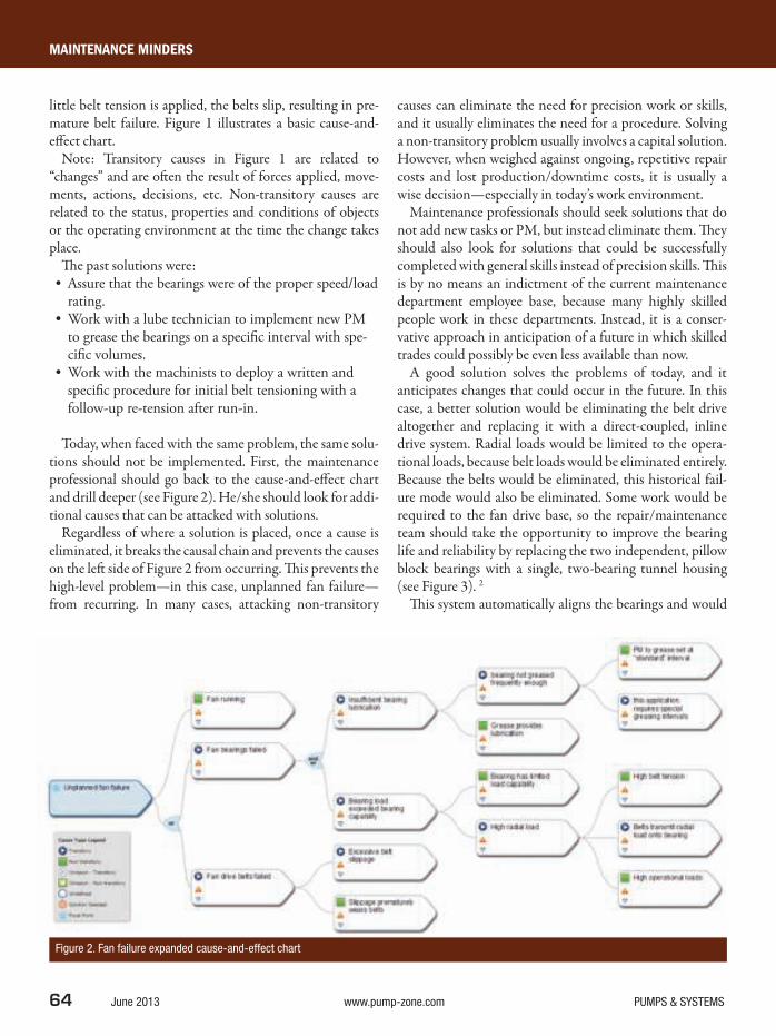
64 June 2013 www.pump-zone.com PUMPS & SYSTEMS
MAINTENANCE MINDERS
little belt tension is applied, the belts slip, resulting in pre-mature belt failure. Figure 1 illustrates a basic cause-and-ef ect chart.
Note: Transitory causes in Figure 1 are related to “changes” and are ot en the result of forces applied, move-ments, actions, decisions, etc. Non-transitory causes are related to the status, properties and conditions of objects or the operating environment at the time the change takes place.
h e past solutions were:• Assure that the bearings were of the proper speed/load
rating.• Work with a lube technician to implement new PM
to grease the bearings on a specifi c interval with spe-cifi c volumes.
• Work with the machinists to deploy a written and specifi c procedure for initial belt tensioning with a follow-up re-tension after run-in.
Today, when faced with the same problem, the same solu-tions should not be implemented. First, the maintenance professional should go back to the cause-and-ef ect chart and drill deeper (see Figure 2). He/she should look for addi-tional causes that can be attacked with solutions.
Regardless of where a solution is placed, once a cause is eliminated, it breaks the causal chain and prevents the causes on the let side of Figure 2 from occurring. h is prevents the high-level problem—in this case, unplanned fan failure—from recurring. In many cases, attacking non-transitory
causes can eliminate the need for precision work or skills, and it usually eliminates the need for a procedure. Solving a non-transitory problem usually involves a capital solution. However, when weighed against ongoing, repetitive repair costs and lost production/downtime costs, it is usually a wise decision—especially in today’s work environment.
Maintenance professionals should seek solutions that do not add new tasks or PM, but instead eliminate them. h ey should also look for solutions that could be successfully completed with general skills instead of precision skills. h is is by no means an indictment of the current maintenance department employee base, because many highly skilled people work in these departments. Instead, it is a conser-vative approach in anticipation of a future in which skilled trades could possibly be even less available than now.
A good solution solves the problems of today, and it anticipates changes that could occur in the future. In this case, a better solution would be eliminating the belt drive altogether and replacing it with a direct-coupled, inline drive system. Radial loads would be limited to the opera-tional loads, because belt loads would be eliminated entirely. Because the belts would be eliminated, this historical fail-ure mode would also be eliminated. Some work would be required to the fan drive base, so the repair/maintenance team should take the opportunity to improve the bearing life and reliability by replacing the two independent, pillow block bearings with a single, two-bearing tunnel housing (see Figure 3). 2
h is system automatically aligns the bearings and would
Figure 2. Fan failure expanded cause-and-effect chart

circle 110 on card or go to psfreeinfo.com

66 June 2013 www.pump-zone.com PUMPS & SYSTEMS
MAINTENANCE MINDERS
be simpler and faster for the mechanics to install while still being capable of handling the fan’s relatively high speeds and operational loads. With these changes, repairs and future maintenance would be simplii ed and would move more toward error-prooi ng the installation. h ese changes would eliminate multiple failure modes—resulting in improved reliability—and would reduce fan failures, the overall objective.
SOLUTIONS FOR THE FUTURE
h e need to improve problem solving approaches is grow-ing. For the past few years, I have served as an advisory board member for the Industrial Technology Department at a nearby university. Many of the board members are from manufacturing companies, many of which supply the auto industry. At a past meeting, the faculty chair asked the board, “What skills do you need most from our graduates now and in the future?”
“Better problem-solving skills,” was the i rst response. I do not believe that this answer is what the faculty expected or wanted to hear. h e faculty chair looked perplexed and then asked about the need for advanced computer aided design/computer aided manufacturing, robotics and 3-D modeling capabilities.
A dif erent board member’s response was, “We will teach them the specii cs of the given technology once they arrive at our company. h e technology is changing so fast that you cannot keep up, nor do you need to. However, we do not have time to teach new engi-neers and technologists how to think. h at is what we need most.”
h e remainder of the advi-sory board nodded in agree-ment. While cutting-edge courses such as 3-D modeling look and sound exciting in
a university’s curricula guide, the advisory board members know that one of the greatest needs they have for adding bottom-line value in today’s market is ef ective problem-solving skills.
If maintenance professionals evaluate their current strat-egies for solving problems, they should consider a slightly new bag of tricks—one that explores solutions that are less people-dependent. h e good news is that these solutions will emerge from the non-transitory causes on the cause-and-ef ect chart that can be determined by drilling deeper. h ese solutions should have the staying power needed, regardless of what happens in the future. P&S
References
1. Bob Williamson, “Is the Skill Shortage Real?” 2013, www.swspitcrew.com/articles/articles.asp?ID=167 & “Growing Your Own,” 2010, www.swspitcrew.com/articles/articles.asp?ID=140
2. SKF, secure.skf.com/group/products/bearings-units-housings/bearing-units/two-bearing-units/index.html
Chris Eckert is president of Sologic, LLC, a provider of root
cause analysis training, software and investigations. Eckert
is a professional engineering, certii ed maintenance and
reliability professional. He was formerly a reliability engineer
with Dow Chemical and Rohm and Haas. He can be reached
at [email protected] or 989-835-3402.
Regardless of where a solution is placed, once a cause is
eliminated, it breaks the causal chain and prevents
the causes to the left from occurring.
Figure 3. Improved bearing installation Image courtesy of SKF

circle 119 on card or go to psfreeinfo.com

EFFICIENCY MATTERS
68 June 2013 www.pump-zone.com PUMPS & SYSTEMS
Legislation and regulations have been implemented in the chemical industry as a direct result of accidents that could
have been prevented if companies had followed necessary safety precautions. h is includes the classii cation, labeling and packaging of chemicals that could potentially pose a threat. For example, in 1967, the Dangerous Substances Directive (67/548/EEC) was passed, and its orange-and-black hazardous substance symbols became instantly recognizable to anyone in the world who was handling these hazardous chemicals—anything from basic cleaning products to acids. However, this applied to Europe only, and as a result, the United Nations Globally Harmonized System of Classii cation and Labeling of Chemicals (GHS) was created in 1992 and standardized by 2000.
In Europe, the most important legislation intro-duced in recent years has been Registration, Evaluation, Authorization and Restriction of Chemicals—better known as REACH. Implemented in June 2007 by the European Union, REACH replaced 40 existing direc-tives. h ere are 73 substances on the Substance of Very High Concern (SVHC) candidate list. h e regulation puts greater responsibility on the industry to manage the risks of chemicals and provide safety information on the substances. However, REACH remains a work in progress.
One other way that the chemical industry is creating a safer environment is through certii cations. Equipment must meet certain standards to gain certii cation and must be considered safe to handle known dangerous chemicals—such as acids, solvents and caustics. In the past, the CE symbol was the recognized symbol for safety. Since 1993, the CE mark has been a mandatory conformity marking for products sold in the European Economic Area. h e CE mark indicates that a product conforms to essential health and safety requirements set in European Directives. In recent years, one symbol has joined CE as a trusted symbol of safety: “Ex,” better known as ATEX.
ATEX
h e ATEX directive is meant to protect employees and the surrounding communities from the risk of explosions. Deriving its title from the French Appareils destinés à être utilisés en ATmosphères EXplosives, ATEX consists of two European Union directives: one for the manufacturer (ATEX 95 equipment directive 94/9/EC) and one for the end user (ATEX 137 workplace directive 99/92/EC).
In July 2003, the EU made the following ATEX directives mandatory for organizations within the EU. Equipment in use before July 2003 can still be used, although a risk assessment showing that the equipment is safe is required. Equipment that is capable of causing an explosion through the equipment’s own potential sources of ignition falls under this mandate. Examples of these types of equipment are any machine, apparatus, i xed or mobile device, control component and instrumentation intended for the gen-eration, transfer, storage, measurement and conversion of energy and/or processing of material.
Hazardous area atmospheres are classii ed into zones based on size, location and the likelihood of an explosion. Zones 0, 1 and 2 specify gas-vapor-mist, while zones 20, 21 and 22 specify dust. h ese classii cations dictate that those properties be protected from sources of ignition. Zones 0 and 20 require Category 1 designation—the highest risk of an explosive atmosphere being present. Other categories are Zones 1 and 21, which fall into Category 2. Zones 2 and 22 require Category 3.
ATEX 95 directive 94/9/EC is designed to allow the free trade of ATEX-conformed equipment and protective systems within the EU by removing the need for separate testing and documentation for each member state. h e regulation applies to all equipment intended for use in explosive environments, including electrical and mechani-cal. Equipment ai xed with the “CE” marking and the “Ex” marking certify that the piece of equipment can be sold any-where within the EU without further requirements.
ATEX: The Symbol of Safety in Dangerous Chemicals HandlingSafety-conscious chemical companies are making ATEX-certii ed pumps and equipment mandatory in their day-to-day operations.
By Edison Brito

PUMPS & SYSTEMS www.pump-zone.com June 2013 69
Some of the most common areas in which a potentially explosive atmo-sphere could exist include of shore platforms, petrochemical plants and mines. h ree preconditions are required for the ATEX directive to apply. First, the equipment should be intended for use in a potentially explosive environment. It should also be under normal atmospheric conditions. Finally, the equipment must have its own ef ective source of ignition.
IGNITION SOURCES
h e ATEX directive dei nes an ef ective ignition source as an event that—in combination with sui cient oxygen and fuel in gas, mist, vapor or dust form—can cause an explosion. Many ignition sources must be taken into account by end users, including:• Lightning strikes• Open fl ames and hot gases• Arcs and fl ashes• Electrostatic discharges• Electromagnetic waves• Ionizing radiation• Hot surfaces• Mechanically generated sparks• Optical radiation• Chemical fl ame irritation
Electrostatic discharge, for example, is considered one of the greatest hazards when handling dangerous chemicals. In this process, static electricity is gener-ated by surface friction when chemicals come in contact with other materials. Typically, this occurs when the product is moved or transferred through pipes, i lters, mixers and/or pumps. Static electricity may accumulate in the liquid (liquid hydrocarbons, in particular). h is can lead to sparking in a l ammable, vapor-air mixture.
Ignitable discharges can occur between an insulated or earthed conductive object and a charged, insulated conductive or non-conductive object. Avoiding electrostatic discharge starts with selecting the right equipment to transfer those chemicals—equipment that meets the criteria of the ATEX directive.
A PUMP’S ROLE IN SAFE CHEMICAL TRANSFER
Dr. Georg Baum is the owner of CTB-Chemical Technologies, a Germany-based company that supplies systems and solutions for the safe transfer of hazardous material in chemical plants. As an authority on the subject of safe, ATEX-compliant chemical transfer applications, Dr. Baum stresses three fac-tors when selecting a pump for dangerous-chemical transfer.
“One important point is the compatibility of the material with the chemi-cal,” Dr. Baum said. “h e second factor is, if we use solvents, for example, we must use the appropriate pump that won’t cause an ignition. h is means using pumps with electric conductive material. h e third factor is suction capability.”
One pump technology that meets all Baum’s criteria is ATEX-certii ed, solid-body, air-operated double-diaphragm (AODD) pumps, which can be built using conductive plastic materials. h is technology of ers the material c
irc
le 1
46 o
n c
ard
or
go t
o p
sfr
ee
info
.co
m
Solutions For Handling
DangerousChemicals
Safe
World Headquarters
Carl-Friedrich-Gauß-Str. 5
47475 Kamp-Lintfort, Germany
O: +49/2842/961-0
F: +49/2842/961-40
www.almatec.de
PSG Euro-Center™
22069 Van Buren Street
Grand Terrace, CA 92313 USA
O: +1 (909) [email protected]
Award-winning Almatec® E-Series Plastic AODD pumps provide safe and reliable performance when handling the most dangerous acids, solvents and caustics.
• Solid block CNC machining
• Polyethylene and PTFE materials, conductive also available for explosion-proof environments (ATEX)
• Ring design structure for improved product containment
• Optional features available (e.g., barrier chamber system) for further safety requirements
• Dry run ability, self-priming, gentle fl uidhandling, no rotating parts, no shaft seals
Where In
novation F
low
s
Contact your local Almatec representative today.

EFFICIENCY MATTERS
70 June 2013 www.pump-zone.com PUMPS & SYSTEMS
compatibility and strong suction that other pump technolo-gies cannot. h e many factors to consider when selecting an AODD pump for a dangerous-chemicals application are discussed in this section.
Material Compatibility
Matching the proper pump to the materials being trans-ferred starts with the housing. Pumps made of polyethyl-ene (PE) have better wear resistance than pumps made of polypropylene (PP), enabling the units to transfer highly abrasive chemicals. Polytetral uoroethylene (PTFE) con-struction, on the other hand, provides the superior chemi-cal resistance necessary in dangerous-chemical transfer. Operators should also focus on the materials of construc-tion for a pump’s internal components. Diaphragms made of ethylene propylene diene monomer (EPDM), PTFE/EPDM-composite or nitrile rubber (NBR) feature large diameters and short strokes with low l exural loads, which ensure uniform delivery regardless of chemical properties.
Conductive Materials
Pumps with non-conductive housing materials are suscep-tible to electrostatic discharge. Static can accumulate in liquid being moved or transferred through a non-conduc-tive pump, leading to sparking in a l ammable, vapor-air mixture. Pumps with conductive PE or PTFE housing are preferred in explosion-proof areas in which l ammable liq-uids are present. h ese conductive PE and PTFE housings enable pumps to meet ATEX requirements.
Strong Suction (Self Priming)
Totes or barrels of chemicals are ot en placed at ground level in protective cabinets with pumps located on the top or to the side of these containers. Strong suction is imperative. AODD pumps, by their nature and design, provide suf-i cient suction to draw l uids from tanks regardless of loca-tion. Other technologies, such as centrifugal pumps, require l uid pressure into the impeller to create suction and l ow. Operators should also consider that AODD pumps of er
superior containment, shear-sensitivity and run-dry capabilities over other pump technologies.
Solid-Body Construction
Solid-plastic-block machining increases the pump’s strength and life cycle while eliminating maintenance concerns. A computer numerical control (CNC) machined solid block of PTFE or PE allows the pump to deal with the harsh-est environments. Plastic injection-molded construction, by comparison, deforms in harsh environments, creating a potential leak path when the temperature varies—regardless of how tight the bolts are torqued. However, with solid-plastic-block machining, no crevices exist for a potential leak path. It is also more robust, and the integrity of the material is stronger. In addi-tion, CNC technology enables tight tolerances, with reduced vibration and greater stability and durability.
Containment
Containment is another important consider-ation when selecting a pump that will ef ec-tively handle and transfer dangerous chemicals. Mechanical seals found in centrifugal pumps, progressive cavity pumps and gear pumps can be prone to failure. Seal failure can lead to bear-ing failure, which results in costly downtime Figure 1. ATEX 94/9/EG directive requirements

PUMPS & SYSTEMS www.pump-zone.com June 2013 71
and unscheduled maintenance. h e safest way to avoid seal failure and avoid product contamination is by removing the seal from the equation. AODD pumps are free of mechani-cal seals and are designed so that the diaphragm acts like a seal. When matched with materials that are appropriate to the chemical being pumped, the diaphragm acts as a gasket, which is not subject to wear from shat friction.
Run Dry
Friction can lead to static discharge, which in turn creates a dangerous environment. When handling chemicals, opera-tors will continue to operate the pump—even at er the chemical has been depleted—to more fully clear the lines. h is is known as running dry. When certain pump tech-nologies run dry, their components can burn and seize, cre-ating a dangerous situation when hazardous chemicals are involved. AODD pumps are designed to run dry. When the l uid is depleted, they pump air with no damage to the pump internals.
Shear Sensitivity
Pumps that have a propensity for shearing or damaging the product typically have meshing teeth or introduce the l uid to multiple moving parts. When transferring chemi-cals, providing gentle handling to eliminate any change to the chemical properties is critical. AODD pumps are con-sidered one of the gentlest pumping technologies available because the l uid is simply drawn into a chamber and then pushed out without contacting moving parts.
Deadheading
Many chemical applications require accurate l ow rates to maintain the consistency and quality of the product. To maintain this consistency, valves on the discharge side of the pump close swit ly, interrupting the product l ow. h is cre-ates a jolt to the pump, also known as deadheading. AODD pumps are designed to handle such start-and-stop deadhead conditions without any adverse ef ects to the product or the pump.
ROBUST AODD PUMP TECHNOLOGY
One robust AODD pump technology meets all the ATEX criteria. h is technology features housing constructed of PE, PTFE, PE-conductive material and PTFE-conductive material. h e PE-conductive and PTFE-conductive pumps
meet the requirements of the ATEX 94/9/EG directive (see Figure 1).
For use in device group IIC without additional protec-tion measures, these plastic AODD pumps also feature electrically conductive PTFE diaphragms to provide safer transfer of chemicals while avoiding dangerous electrostatic discharge. h ey continue to pump even at er the chemical has been depleted.
By comparison, other pumps require operators to pump nitrogen, water or carbon dioxide at er the l uid transfer has been completed to avoid potentially dangerous electrostatic discharge. h ese plastic AODD pumps pump air with no damage to the pump internals. h e pumps’ diaphragms have a large diameter and short stroke with low l exural load, ensuring uniform delivery regardless of the diaphragm’s material of construction. h e EPDM diaphragms are con-ductive as standard.
h ey are available in seven sizes, from 6 to 76 millimeters (¼ inch to 3 inches), with maximum temperatures to 120 C (248 F). h e pumps feature maximum l ows to 800 liters per minute (210 gallons per minute); suction lit to 5 meters (16.4 feet), dry, 9.5 meters (31.2 feet), wet; and maximum solids sizes to 15 millimeters (9⁄16 inch).
CONCLUSION
Chemical plants have a great responsibility to take every necessary precaution to protect their employees and the surrounding communities. During the past half-century, legislation has been put in place because of a number of preventable chemical accidents. While adhering to these rules remains mandatory, chemical companies worldwide need to consider installing ATEX-conformed equipment as standard, despite it only being required in the EU. ATEX is widely considered the accepted symbol of safety, and using ATEX-rated pumping equipment can provide operators with the peace of mind they need to work in potentially dangerous environments. P&S
Edison Brito is the director, Global Segment Marketing,
Chemical, with Pump Solutions Group (PSG). He can be
reached at [email protected].
Dover Corporation’s PSG is comprised of several pump
brands—including Abaque, Almatec, Blackmer, Griswold,
Neptune, Maag, Mouvex, Quattrol ow and Wilden. For more
information, visit www.psgdover.com.
Robust AODD pump technology meets all the ATEX criteria.

72 June 2013 www.pump-zone.com PUMPS & SYSTEMS
SEALING SENSE
Many methods are used to tighten fasteners. h e most common is using a hand or impact wrench and
“mechanic’s feel.” h e installer tightens the fastener until it feels tight. While this process is acceptable for non-critical applications, it is unacceptable when greater tension accuracy is required.
In more critical situations, the i rst thought may be to use a torque wrench. However, what torque should be used, and will the required tension be achieved? h is “Sealing Sense” is intended to help end users choose the best torque to apply for their applications. It will demonstrate the impor-tance of lubrication and describe procedures that provide the required compressive load on a gasket using torque. It will also identify other important considerations for proper assembly.
A more comprehensive discussion of the entire assem-bly process for bolted l ange joints can be found in ASME Standard PCC-1-2010. Information provided in this “Sealing Sense” is consistent with that document’s guidelines.
A word of caution, torque is not the most accurate way to tension a fastener. h e amount of tension achieved from torque is af ected by a number of variables. Friction is the most important, and it is dii cult to control. High friction results in low tension, and low friction results in high ten-sion. At best, torque tension results will vary in un-lubricated fasteners by +/-25 percent. Using a lubricant can improve this to about +/-15 to 20 percent.
IMPORTANT STEPS
To ensure the appropriate tightening of fasteners, certain steps should be followed:• Determine the tension needed for each fastener.• Choose a fastener size and grade with strength that
can provide the required tension without being overloaded.
• Calculate the required torque.• Use a calibrated torque wrench.• Apply torque correctly to evenly load all the fasteners.• Use only through hardened washers.
To determine the tension needed on each fastener, estab-lish the total compressive load required for the application. Divide this by the number of fasteners to i nd the tension needed for each.
Next, choose the fastener size and grade. In most cases, end users already know the size since the application usu-ally determines the required size. Keep in mind that a i ne-threaded fastener of a given diameter is able to tolerate a higher load than a coarse thread of the same size. If a load is needed that is higher than a coarse-threaded fastener has the ability to provide, a i ne-threaded fastener of the same grade and size can provide more tension and may be able to meet the need. Tables 2 and 3 list common grades, stress areas and maximum loads permitted using U.S. customary and International System of Units (SI) bolts. Never exceed these loads.
HOW TO CALCULATE REQUIRED TORQUE
A common method of calculating the required target torque uses the formula below:
T = (KDF) / 12
Where: T = Torque, foot pounds K = Nut factor (torque coei cient resulting from esti-
mated coei cient of friction) D = Nominal diameter of the bolt, inches F = Tension, pounds
Improved Torque TensionHow does lubrication affect fastener torque and resultant tension?
By FSA member Dave Hageman
K Values
Un-Lubricated Lubricated
Un-plated steel fastener 0.2 0.17
Zinc-plated fastener 0.17 0.15
Cadmium-plated fastener 0.15 0.12
Stainless steel fastener 0.3 0.2
Table 1. Nut factors for molybdenum disulfi de lubricant

PUMPS & SYSTEMS www.pump-zone.com June 2013 73
Dividing by 12 gives foot pounds. If inch pounds units are required, do not divide by 12.
SAMPLE TORQUE CALCULATION
h is example assumes that four ⅜ -16 bolts must provide a total load of 20,000 pounds. Each step for applying the cor-rect tightening should be followed:• Step 1—Tension needed for each fastener: 20,000 / 4
fasteners = 5,000 pounds needed for each fastener.• Step 2—h e size is ⅜ -16, which is a ⅜ -inch nominal
diameter fastener with 16 threads per inch. Using Table 2, a ⅜ -16, Grade 5 fastener has a maximum load capacity of 6,510 pounds. h is fastener is appro-priate for this application. For this example, assume it is an un-plated steel fastener.
• Step 3—Calculate the torque. h is step can be tricky. Since friction variation will cause tension variation, controlling the friction as much as possible is important. Lubricants are used to do this. h ey must be applied to the threaded surfaces of the bolt, the nut and under the bolt head. Many lubricants are avail-able, and they do not all work the same. Typical brush-on, thread lubricants are not always the best choice. h ey are intended more for facilitating fastener removal than controlling tightening friction. One of the lubricants often used (when it is permitted) is molybdenum disulfi de grease with an extreme pressure (EP) additive. h is lubricant is used in this example.
Using the steps above:
T = (K x 0.375 x 5,000)/12
Where:D = 0.375 (⅜ -inch) F = 5,000 pounds
Only K remains an unknown. Table 1 shows the values available. Keep in mind that K values are all best approxi-mations. For a lubricated, un-plated steel fastener, K = 0.17.
h erefore:T = (0.17 x 0.375 x 5000) / 12 = 27 foot pounds
SIZE DIA. Threads
Per
Inch
STRESS
AREA
Grade 2 300 SS Grade 5 B7 Grade 8 Socket
Head Cap
Screws
Max Max Max Max Max Max
INCHES SQ INCH LOAD LBS LOAD LBS LOAD LBS LOAD LBS LOAD LBS LOAD LBS
1/4 0.2500 28 0.0364 1886 1638 3058 3185 3822 4586
0.2500 20 0.0318 1647 1431 2671 2783 3339 4007
5/16 0.3125 24 0.0580 3004 2610 4872 5075 6090 7308
0.3125 18 0.0524 2714 2358 4402 4585 5502 6602
3/8 0.3750 24 0.0878 4548 3951 7375 7683 9219 11063
0.3750 16 0.0775 4015 3488 6510 6781 8138 9765
7/16 0.4375 20 0.1187 6149 5342 9971 10386 12464 14956
0.4375 14 0.1063 5506 4784 8929 9301 11162 13394
1/2 0.5000 20 0.1599 8283 7196 13432 13991 16790 20147
0.5000 13 0.1419 7350 6386 11920 12416 14900 17879
9/16 0.5625 18 0.2030 10515 9135 17052 17763 21315 24157
0.5625 12 0.1820 9428 8190 15288 15925 19110 21658
5/8 0.6250 18 0.2560 13261 11520 21504 22400 26880 30464
0.6250 11 0.2260 11707 10170 18984 19775 23730 26894
3/4 0.7500 16 0.3730 19321 16785 31332 32638 39165 44387
0.7500 10 0.3340 17301 15030 28056 29225 35070 39746
7/8 0.8750 14 0.5090 26366 22905 42756 44538 53445 60571
0.8750 9 0.4620 23932 20790 38808 40425 48510 54978
1 1.0000 14 0.6800 35224 30600 57120 59500 71400 80920
1.0000 12 0.6630 34343 29835 55692 58013 69615 78897
1.0000 8 0.6060 31391 27270 50904 53025 63630 72114
1 1/8 1.1250 12 0.8560 44341 38520 71904 74900 89880 101864
1.1250 7 0.7630 39523 34335 64092 66763 80115 90797
1 1/4 1.2500 12 1.0730 55581 48285 90132 93888 112665 127687
1.2500 7 0.9690 50194 43605 81396 84788 101745 115311
Chart calculated based on industry standards (ISO, IFI, ASTM etc.)
Table 2. Bolt specifi cations – U.S. customary units
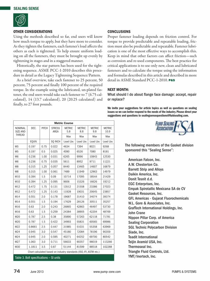
SEALING SENSE
74 June 2013 www.pump-zone.com PUMPS & SYSTEMS
OTHER CONSIDERATIONS
Using the methods described so far, end users will know how much torque to apply, but they have more to consider. As they tighten the fasteners, each fastener’s load af ects the others as each is tightened. To help ensure uniform load-ing on all the fasteners, they must be brought up evenly by tightening in stages and in a staggered manner.
Historically, the star pattern has been used for the tight-ening sequence. ASME PCC-1-2010 describes this proce-dure in detail as the Legacy Tightening Sequence/Pattern.
As a brief overview, take each fastener to 25 percent, 50 percent, 75 percent and i nally 100 percent of the required torque. In the example using the lubricated, un-plated fas-tener, the end users would take each fastener to 7 (6.75 cal-culated), 14 (13.7 calculated), 20 (20.25 calculated) and i nally, to 27 foot pounds.
CONCLUSIONS
Proper fastener loading depends on friction control. For torque to provide predictable and repeatable loading, fric-tion must also be predictable and repeatable. Fastener lubri-cation is one of the most ef ective ways to accomplish this. Keep in mind that other factors can af ect friction—such as corrosion and re-used components. h e best practice for critical applications is to use only new, clean and lubricated fasteners and to calculate the torque using the information and formulas described in this article and described in more detail in ASME Standard PCC-1-2010. P&S
NEXT MONTH:
What should I do about l ange face damage: accept, repair
or replace?
We invite your suggestions for article topics as well as questions on sealing
issues so we can better respond to the needs of the industry. Please direct your
suggestions and questions to sealingsensequestions@l uidsealing.com.
Metric Course
NOMINAL
SIZE AND
THREAD
DEC. PITCH
STRESS
AREA
METRIC
5.8
METRIC
8.8
METRIC
9.8
METRIC
10.9
Max Max Max Max
EQUIV. SQ INCH Load Lbs Load Lbs Load Lbs Load Lbs
M5 0.197 0.75 0.022 4634 7394 8021 9268
M5 0.197 0.5 0.025 4090 6526 7080 8181
M6 0.236 1.00 0.031 6265 9996 10843 12530
M6 0.236 0.75 0.035 5611 8952 9711 11221
M8 0.315 1.25 0.057 8440 13465 14607 16879
M8 0.315 1.00 0.061 7489 11949 12963 14979
M10 0.394 1.5 0.09 10714 17095 18544 21429
M10 0.394 1.25 0.095 9606 15326 16626 19212
M12 0.472 1.75 0.131 13512 21558 23386 27023
M12 0.472 1.25 0.143 11928 19031 20645 23857
M14 0.551 2.0 0.178 19687 31410 34074 39374
M14 0.551 1.5 0.194 17629 28126 30511 35257
M16 0.63 2.0 0.243 26865 42863 46497 53730
M16 0.63 1.5 0.259 24384 38905 42204 48769
M20 0.787 2.5 0.38 35890 57263 62118 71781
M20 0.787 1.5 0.422 34993 55831 60565 69986
M22 0.8661 2.5 0.447 31985 51031 55358 63969
M24 0.945 3.0 0.547 45180 72084 78196 90359
M24 0.945 2.0 0.595 40271 64252 69700 80542
M27 1.063 3.0 0.711 56633 90357 98019 113266
M30 1.1811 3.5 0.87 51144 81599 88518 102288
Chart calculated based on industry standards (ISO, IFI, ASTM etc.)
Table 3. Bolt specifi cations – SI units
The following members of the Gasket division
sponsored this “Sealing Sense”:
American Falcon, Inc.
A.W. Chesterton Co.
Barrett Strip and Alloys
Daikin America, Inc.
Donit Tesnit d.d.
EGC Enterprises, Inc.
Empak Spirotallic Mexicana SA de CV
Gasket Resources, Inc.
GFL Americas - Gujarat Fluorochemicals
W.L. Gore & Associates, Inc.
GrafTech International Holdings, Inc.
John Crane
Nippon Pillar Corp. of America
Sealing Corporation
SGL Technic Polycarbon Division
Slade, Inc.
Teadit International
Teijin Aramid USA, Inc.
Thermoseal Inc.
Triangle Fluid Controls, Ltd.
YMT/Inertech, Inc.

86th Annual Water Environment
Federation Technical Exhibition
and Conference
McCormick Place South,
Chicago, Illinois USA
Conference: 5 – 9 October 2013
Exhibition: 7– 9 October 2013
SAVE THE DATES
30 August Phone, fax, and mail registration deadline
30 August Cancelation/substitution deadline
BRINGING THE GLOBAL WATER COMMUNITY TOGETHER
Covering the full water cycle, WEFTEC is your
leading source for research, design, and operation
of collection systems, stormwater management,
wastewater treatment plants, water reuse and
supply, watershed management, and much more.
Through the largest annual water quality exhibition,
WEFTEC connects operators, managers,
consultants, and buyers with more than 900
leading manufacturers and service providers.
WEFTEC is the greatest opportunity for the
international water community by creating
business opportunities for individuals and
organizations with global perspectives.
THE LARGEST ANNUAL WATER QUALITY CONFERENCE AND EXHIBITION ON THE PLANET
REGISTRATION IS NOW OPEN
www.weftec.orgcircle 113 on card or go to psfreeinfo.com

HI PUMP FAQs
76 June 2013 www.pump-zone.com PUMPS & SYSTEMS
A. For outdoor installations, the pump components should be covered with rainproof tarps during installa-tion to protect them from the elements. h is is particularly important during freezing conditions to prevent water from collecting in pump cavities and causing freezing damage.
h e pump and equipment, as shipped, have adequate protection for short-term storage (up to three months) in a covered, dry and ventilated location at the jobsite prior to installation. However, if the equipment will be subjected to extended storage (more than three months), then the
standard warranty of the equipment may be af ected. In this case, the equipment manufacturer should be advised about the extended storage duration when the pump is specii ed and/or ordered so that special, long-term storage protection can be provided before shipment to the jobsite.
For pumps that require onsite assembly, a clean, drained area should be provided next to the point of installation. h e area should be of adequate size for placing the pump components and driver in the sequence in which they will be installed. Protective covers should be let on all pump
Q. What considerations should be made for outdoor rotodynamic pump installations?
Q. What is a rotodynamic vertical pump? What pumps are classifi ed in this way?
A. Rotodynamic pumps are kinetic machines in which energy is continuously imparted to the pumped l uid by using a rotating impeller, propeller or rotor. h e most common types of rotodynamic pumps are centrifugal (radial l ow), modii ed radial l ow (turbine pumps), mixed l ow and axial l ow (propeller pumps).
h ese pumps, particularly the radial l ow and mod-ii ed radial l ow types, are usually designed for mul-tistage operation, by bolting or threading individual bowls together. h e pumping element (bowl assem-bly) is usually suspended by a column pipe, which also carries the liquid from the bowl (assembly) to the dis-charge opening.
Rotodynamic vertical pumps (see Figure 2.1.3) are normally classii ed as deep well, short set or submers-ible motor-driven. h e driver for these pump coni gurations is mounted either on the discharge head (lineshat pumps); directly to the bowl assembly, either above or below (for pumps with submersible motors); or in a horizontal
coni guration, such as an electrical motor or engine, driving through a right-angle gear.
For more information about rotodynamic vertical pumps, see ANSI 2.1-2.2 Rotodynamic (Vertical) Pumps for Nomenclature and Dei nitions. P&S
Outdoor Installations, Rotodynamic Vertical Pumps & Drooping HeadBy The Hydraulic Institute
Figure 2.1.3. Vertical pump types—vertically suspended, single & multistage

PUMPS & SYSTEMS www.pump-zone.com June 2013 77
openings until actual installation to prevent dirt and foreign objects from entering the pump. Protective coatings should likewise be let on machined surfaces to prevent rusting.
All pumps require regular maintenance. h erefore, the location of all pump discharge piping (and suction piping when applicable), auxiliary equipment, and control and starting panels should provide adequate access for mainte-nance. Suitable l oor space and working room should also be provided for repair, including parts placement.
To minimize frictional head loss, the pump should be located where it can be installed with a short and direct discharge pipe and with the least number of elbows and
i ttings. If practical, it should be placed so that it will be accessible for inspection during operation. In addition, the equipment selected should be compatible with the environ-ment. Pumps and drivers (other than submersible types)and controls should be protected against l ooding. If ever in doubt, end users should refer to the manufacturers’ installa-tion, operation and maintenance (IOM) manuals for IOM information specii c to their equipment.
For more information on installation considerations for rotodynamic pumps, see ANSI/HI 1.4 Rotodynamic (Centrifugal) Pumps for Manuals Describing Installation, Operation, and Maintenance. P&S
A. Some rotodynamic pump head versus rate-of-l ow curves exhibit a characteristic commonly referred to as droop (see Figure 9.6.3.3.8a). A drooping head versus rate-of-l ow curve is one in which the zero rate of l ow head (shut-of head) is lower than the maximum head on the curve.
h is phenomenon ot en occurs in low- to medium-spe-cii c-speed pumps:
Specii c speed (Ns) < 68 (N
s < 3,500)
Q. What is droop, and does it affect rotodynamic pump operation?
FOOD PROCESSING PUMPS
Cornell Hydro-Transport Food Process pumps are designed and manufactured with the sole purpose of pumping delicate food products. Cornell food pumps have the lowest product damage rates in the industry, are the pump of choice for food processors around the world and were the original Hydro-Transport pump manufacturer.
COPYRIGHT© CORNELL PUMP COMPANY, 2012, ALL RIGHTS RESERVEDwww.cornellpump.com
い" ろppqxcvkxg"ukping"rqtv"korgnngt"ykvj"qや"ugv"xqnwvg
い" Quality and reliability
い" Available in sizes ranging from 4” to 12” discharge
い" Ductile iron, all stainless steel or iron w/ stainless steel impellers
い" Optional Cycloseal© upgrade
circle 140 on card or go to psfreeinfo.com

HI PUMP FAQs
78 June 2013 www.pump-zone.com PUMPS & SYSTEMS
h ese pumps have been designed to optimize ei ciency. Droop does not present an application problem unless one or more of the following con-ditions exist:• h e system head curve intersects the pump
curve at two or more rates of fl ow.• h e pump is operated in parallel with one
or more other pumps at a system head that is greater than the pump shutoff head.
• A continuously rising curve is required for control purposes. For example, systems that require pressure control.
Applying pumps with drooping head curves in these conditions may cause the pump to be pushed back to shutof or to “hunt” between two operat-ing points. Neither condition is desirable. In these cases, the allowable operating region may require further limitation and/or appropriate system controls may be implemented. In the absence of any of the above conditions, pumps with drooping head curves can perform as well as pumps with continually rising curves.
For more information about rotodynamic pump operating conditions, see ANSI/HI 9.6.3 Rotodynamic (Centrifugal and Vertical) Pumps – Guideline for Allowable Operating Region. P&S
Pump FAQs® is produced by the Hydraulic Institute (HI) as a service to pump
users, contractors, distributors,
reps and OEMs. For more informa-
tion, visit www.pumps.org.
Figure 9.6.3.3.8a. Pump head versus rate-of-fl ow curve illustrating a droop
circle 156 on card or go to psfreeinfo.com circle 155 on card or go to psfreeinfo.com
– Positive Displacement Pumps
– Centrifugal Pumps
– Specialty & Other Pumps
– Industrial Valves
– Pneumatic & Hydraulic Valves
– Industrial Automation &
Process Control
– Electric Motors & Drives
– Actuators
– Compressors
– Custom Research
– White Papers
Comprehensive Industry Coverage
Frost & Sullivan evaluates and implements
effective growth strategies. We employ 50
years of experience in partnering with Global
1000 companies, emerging businesses and the
investment community from more than 40
offices on six continents.
Visit us at www.frost.com
For more information, contact Britni Myers
at 210-477-8481 or [email protected]

circle 109 on card or go to psfreeinfo.com

80 June 2013 www.pump-zone.com PUMPS & SYSTEMS
BUSINESS OF THE BUSINESS
From increasing raw material costs to changing food consumption patterns, the food and beverage industry
has faced a number of changes during the past couple years. h e U.S. food and beverage market is one of the largest in the world and contributes more than 14 percent to the country’s total manufacturing output. Additionally, the demand for food products is less susceptible to changes in the economic landscape and was one of the industries least af ected by the 2009 economic recession.
h e manufacturing of processed foods increased as the demand for ready-to-eat home foods rose versus eating at restaurants. An increased sale of frozen food and private labels occurred during the recession because these helped consumers cut down on their household expenses. Although inl ation, supply chain management and quality control are some of the major challenges faced by the industry, demand for processed foods continues to drive the food and bever-age industry.
h is increasing processed food industry faces pressure from public agencies and consumers to produce healthy products while maintaining right margins. Nutritious and
organic foods are expected to have a large impact on the industry. To remain competitive, food manufacturers are making headway by taking several positive steps toward the health and wellness trend. Reformulation of products to have high nutritional value, partnering with organizations for health accreditations and adhering to government regu-lations proactively are a few of the steps being taken.
Also, growing concerns about obesity and other heart-related diseases increased awareness of diet-related food segments. Most manufacturers are revamping their prod-uct of erings with a special focus on nutritional content. For example, the salt and sugar content is being reduced in a number of products to become healthy snack options. Increased consumer demand because of these changes is likely to accelerate the growth of this segment into one of the largest in the food and beverage industry. Rising costs have an impact on the industry, but with consumers’ increas-ing demand for good food and beverages, they are willing to pay a premium.
h e food and beverage industry is highly fragmented in the U.S., with an increasing number of mergers and acquisi-
tions taking place. Consolidation, rising costs, changing consumer preferences and increasing regu-lations are dramatically chang-ing the landscape of the indus-try. Innovations and technology will play a key role in successful strategies. As a result, a proactive approach to addressing regula-tory issues—paving the path toward a risk-free business—is most important.
FDA’S FOOD SAFETY
MODERNIZATION ACT AND
ITS INFLUENCE
Food manufacturing is com-plex—including the equipment design, manufacturing processes,
Food & Beverage Industry Pump MarketThe total pump market within this segment is steadily growing in the U.S.
By Sakthi Pandian & Anand Gnanamoorthy, Frost & Sullivan
• Comprehensive, science-based preventive control across the food supply
• Preventive Controls
• Safety Standards
• Avoid Intentional Contamination
Prevention
• Necessary for FDA to provide an oversight of facilities, ensure compliance with requirements and respond effectively when needed
• Mandatory recall
• Record Access
Inspection, Compliance and Response
• FDA has authority to ensure imported foods meet U.S. standards and to deny entry
• Importers can obtain third party certification from FDA recognized organizations
Import Safety
• FDA’s collaboration with other domestic and foreign agencies can facilitate effective work towards achieving public health goals
Enhanced Partnership
• Suspensions of registration • Product Tracing
The four elements of the FSMA

PUMPS & SYSTEMS www.pump-zone.com June 2013 81
packaging and distribution. With numerous concerns from several public bodies regarding food safety, the U.S. Food and Drug Administration (FDA) designed the Food Safety Modernization Act (FSMA) to fortify the existing system. h e FSMA is divided into four main elements: • Prevention• Inspection, compliance and response• Import safety • Enhanced partnership
h e ultimate goal is to achieve an impeccably clean and disinfected result under a tight control of costs.
h e FSMA’s primary focus is prevention. To implement preventive controls, the processors are required to evaluate the hazards in their operations and implement and moni-tor measures to prevent accidental and deliberate contami-nation. h ey are also required to have a corrective plan in case of a breach. h e FDA ensures the adequacy and proper implementation of these plans, called Hazard Analysis and Risk-Based Preventive Controls (HARPC), along with a mandatory recall to swit ly remove contaminated products from the market. To maintain an ei cient inspection system, the FDA will strengthen its collaboration with many food safety agencies.
h e FSMA has been acclaimed as the most com-prehensive food safety law in the last three decades. It places the responsibility on manufacturers to enforce its provisions within the specii ed compliance dates, which vary from one year to three years based on the size of the facil-ity. Fierce competition and the need to optimize costs require manufacturers to take a proac-tive stand in implementing the system by documenting hazard plans for prevention and cor-rective measures, evaluating traceability and recall plans,
and actively participating in the FDA’s upcoming activities. h ese factors hold good for the equipment manufactur-ers and for those who must adhere to these requirements during product design.
h e food properties are impacted by the conditions inside the equipment—such as shear rate, residence time, temper-ature history and moisture levels—which can impact food quality. Some examples in design consideration include the requirement of surfaces in contact with food to be stain-less steel, because stainless steel of ers excellent corrosion protection and is not af ected by the pH of the food. h e hygienic designs should be maintained by minimizing the dead spots and supporting cleaning-in-place/sterilization-in-place (CIP/SIP) requirements.
PUMP MARKET OUTLOOK
h e total pump market in the U.S. food and beverage indus-try was estimated at $604.5 million in 2012, which is steadily growing at a compound annual growth rate (CAGR) of 5.9 percent. With increasing investment in new expansions and the revamping of older facilities, pump manufacturers expe-rience a constant growth in demand for pumps with sani-tary requirements.
5.0
6.0
7.0
400.0
500.0
600.0
700.0
800.0
900.0
1,000.0
2010 2011 2012 2013 2014 2015 2016 2017 2018 2019
Gro
wth
Ra
te (
%)
Ma
rke
t S
ize
($
Mil
lio
ns
)
Total Pump Market in Food and Beverage North America, 2010-2019
CAGR = 5.9%
Note: All figures are rounded. The base year is 2012. Source: Frost & Sullivan analysis.
Pump market overview
The total pump market in the U.S. food and beverage industry was esti-
mated at $604.5 million in 2012, which is steadily growing at a compound
annual growth rate (CAGR) of 5.9 percent.

BUSINESS OF THE BUSINESS
82 June 2013 www.pump-zone.com PUMPS & SYSTEMS
h e total pump market for sanitary applications in the food and beverage industry in the U.S. is projected to reach $657 million in 2019. Positive displacement pumps will experience a higher growth rate because of their functional advantages in food processing. h ese pumps are benei cial to the shear-sensitive nature of these products because the
l ow rates can be uniformly controlled and product loss is minimized.
Diaphragm and peristaltic pumps are gaining popular-ity because the pumped product does not contact their metal surfaces. h e tubing in these pumps can be regularly replaced to adhere to sanitary requirements, maximizing
production up-time.With changes in regulations, food
manufacturers are becoming proac-tive to ensure maximum safety in production. h e FSMA has provi-sions making a number of manda-tory changes in the Current Good Manufacturing Practices (cGMPs) and Sanitation Standard Operating Procedures (SSOPs). As a result, the demand for pumps fuli lling sanitary requirements is expected to increase further. h e expectations from pumps catering to dif erent segments—for instance, the juice and seafood seg-ments that have already been covered by hazard analysis and critical control points (HACCPs)—vary according to the extensiveness of the regulations.
Pump manufacturers have many opportunities to increase their growth in the future. Innovation in handling the regulatory changes and extending services to facilities to help them pre-pare safety plans are some strategies for pump manufacturers to move to the next level. Also, smart pumps are creating interest in the regulatory and ei ciency fronts and play a promising role in the pump market. P&S
Sakthi Pandian is a research analyst for
Frost & Sullivan’s Industrial Automation and
Process Control practice. Senior Analyst Anand
Gnanamoorthy also works on this team. Both can
be reached at [email protected].
an is a researrch analyst forrch

PUMPS & SYSTEMS www.pump-zone.com June 2013 83
PRACTICE & OPERATIONS
Sugar processing requires pumping heavy and sometimes abrasive liquids such as molasses, black liquor, magma
and tailings. h e liquids are ot en hot and tend to quickly crystallize if the product remains inside pumps and lines and then cools. A heavy, industrial positive displacement pump is required to handle such applications. Because of advancements in wet-end and overall pump design, rotary lobe pumps of er signii cant advantages to sugar processors—such as improved product handling, lower life-cycle costs and reduced maintenance.
Rotary lobe pumps are part of the positive displacement group. h ey create l ow by trapping liquid from the suction side, carrying it through the pump and expelling it out the discharge side. During operation, two rotors mesh together and rotate in opposite directions (see Figure 1). h e rota-tion forms cavities between the rotors and wet-end housing. h e liquid that i lls the cavities is carried through the pump and expelled out the discharge side.
MOLASSES
h e major hurdles when dealing with molasses (the “mother liquor” in sugar processing) are viscosity, temperature and crystallization. Molasses is available in many varieties. Each type dif ers in viscosity and solids content depending on its source—cane, sugar beets or another source.
During processing, molasses can be hot—at times approaching 150 F. All factors combined, molasses can be a tough application for pumps.
Viscosity
Rotary lobe pumps are designed to operate with dif erent
levels of slip. h e slip is induced because the rotor tips do not touch the pump housing. As viscosity increases, the slip drastically decreases, and the overall ei ciency of the pump increases as a result. h is also applies to other posi-tive displacement pumps commonly used for molasses, such as gear pumps. h ey too become more ei cient as viscosity increases.
h e rotary lobe pump is advantageous for processes involving molasses. Although slip is a factor, it is not as detrimental to the overall ei ciency as some other positive displacement pump designs. h ese pumps are well-suited to handle thinner i rst molasses up to heavy, black strap molas-ses without a major change in performance.
Temperature
Temperature af ects rotary lobe pumps dif erently depend-ing on the wet-end materials chosen by the manufacturer for each application. Material options vary among brands. Some manufacturers of er elastomer-coated rotors that use materials such as nitrile rubber (NBR) or ethylene propyl-ene diene monomer (EPDM). h ese materials are great solutions for molasses pumping as long as the liquid never surpasses 165 F. h e elastomer can handle these tempera-tures, but they tend to swell, which leads to damage to the rotors if the pump seizes.
h e other caveat to using elastomers is an understanding of how the facility’s maintenance staf cleans the equipment. If steam is used to clean inside the lines, pumps and other devices, then using elastomers is not an option. h e high temperature of the cleaning process can cause catastrophic damage to elastomer-coated rotors.
Many manufacturers also of er solid metal rotors. Metal rotors are available in materials from mild steel, hardened steel, coated steel (such as tungsten carbide) and stainless steel. Brands that of er elastomer-coated and solid metal rotors typically specify the coated ver-sion if possible. Elastomer-coated rotors
Rotary Lobe Pumps in Sugar ProcessingThis pump type manages the temperature and viscosity challenges of handling this difi cult product.
By Marino Curati, Vogelsang
Figure 1. Rotary lobe pump operation

84 June 2013 www.pump-zone.com PUMPS & SYSTEMS
are less expensive and better if solids are present in the pumped l uid. Solid metal rotors require precision machin-ing. h ey also have the added cost of simply needing more metal compared to a rough casted core.
Added costs aside, molasses applications ot en require solid metal rotors. An advantage is that solid metals handle high temperature and high abrasives exceptionally well. h e pump will be well-suited for operation in a process with unpredictable viscosity and temperature conditions. In addition, the pump would be unaf ected if steam cleaning of the system is required.
Crystallization
h e natural hardening process that occurs as molasses cools requires thorough cleaning of the system at er a run of prod-uct to prevent build-up and clogging. h is af ects many aspects of the overall system but can be particularly hard on pumps if they are not coni gured properly for the applica-tion. Seals are particularly vulnerable to crystallized molas-ses build-up. Manufacturers of er many sealing systems—from basic packing-style seals to split-face mechanical seals and water-l ush mechanical sealing systems.
Each seal system design has its advantages and disadvan-tages. Even with adequate system cleaning, pump seals will experience some degree of crystallized molasses. h e ideal seal choice will handle a reasonable degree of build-up and prevent product leakage.
Sometimes seal choice is simply a matter of factoring cost and maintenance against performance. Pumps that use low-cost and low-maintenance packing-style seals ot en allow gallons of molasses to leak out of the pump and onto the l oor. Conversely, pumps with complex water l ush systems to maintain seal lubrication ensure that the product remains in the pump, but complex systems can add cost and main-tenance time.
A happy medium in terms of maintenance and perfor-mance can be found in brands that use a cartridge mechani-cal seal that is back-pressurized and compatible with high-temperature and abrasive liquids.
h e back pressure comes from adding positive pressure to a buf er chamber behind the seals. h is neutralizes the com-bined pressure in the wet-end and prevents the seals from experiencing excess pressure.
MUD CLARIFIER/THICKENER UNDERFLOW
Depending on the size of the clarii er, underl ow mud removal applications are ot en high volume and involve multiple pumps. Single-acting diaphragm pumps are ot en used to move the l uid and solid mixture from mud clarii -ers. Typically, up to six diaphragms may work to empty one clarii er. One crank arm is ot en running three diaphragms each. Although the diaphragms are well-suited for handling the thick mud, they consume a great deal of electric power to run the compressor(s).
In terms of the application itself, the major issues are capacity, abrasives, solids and sometimes temperature. h e waste tailings contain heavy amounts of sand and other damaging solids. Rotary lobe pumps have advantages when handling clarii er underl ow.
Capacity
h e delivery rates of rotary lobe pumps vary by brand. h ey are ot en available in capacities well over 4,000 gallons per minute. Installing one large pump can eliminate the need for multiple pumps while maintaining the required l ow.
In the same step, when choosing an assembly type that is either direct-coupled or V-belt-driven, the compressor can be eliminated. Depending on the compressor system in use, an electric motor drive can reduce the required horsepower by as much as 75 percent. Added benei ts include reduced maintenance and a smaller footprint.
Abrasives
Rotary lobe pumps can safely handle the sand and other abrasives found in the waste tailings of the clarii er. In addi-tion to solid metal rotors, some brands of er rotors with l ame spray coatings. h ese coatings, such as tungsten car-bide, are extremely wear-resistant and hold up well against heavy grit. When the application requires high-wear coat-ings, end users should specify that the other wet-end com-ponents have the same or compatible coating.
Components and wet-end design vary widely by brand. However, most major brands feature some type of adjustable and replaceable upper and lower housings as well as front and rear l at wear plates. In high-wear applications, choos-ing a brand that of ers diverse wet-end material options and a wet-end design that allows for easy maintenance will reduce spare parts cost and maintenance time.
Rotary lobe pumps offer signii cant advantages to sugar processors—
such as improved product handling, lower life-cycle costs and reduced
maintenance.
PRACTICE & OPERATIONS

PUMPS & SYSTEMS www.pump-zone.com June 2013 85
MAGMA/MASSECUITE
Magma/massecuite is a mixture of liquids, juices and crys-tals that result from the crystallization process. Metal lobe l apper valve pumps that are almost always found in magma and massecuite pumping applications are purpose built and have been used in this application for decades. Many of these pumps have been in operation for more than 30 years. Even with the established use of this single rotor pump, the modern, two-rotor lobe pump of ers distinct advantages.
Pulsation
Magma and massecuite should be pumped with as little pul-sation as possible. Pulsation is bad for the product and con-stant hammering of the liquid is bad for the facility’s infra-structure, equipment and work environment. By design, the single rotor hinged l apper pump creates pulsation. h e rotor hits the l ap, which expels trapped liquid from the pump.
By comparison, the two-rotor lobe pump meshes the rotors to create the positive displacement. However, rotary lobe pumps vary in performance when measuring pulsation. Pulsation, when applied to rotary lobe pumps, is directly related to rotor design. Although many styles of rotors have been developed, the rotor design that most major brands would use for a sugar process application would be some variation of the examples shown in Figures 2, 3 and 4.
h ese pumps can have two basic types of rotors: straight and balanced. A straight rotor (see Figures 2 & 3) can have two, three or more lobes. h ey are straight from front to back and could be elastomer coated, solid metal or l ame spray coated.
h e second type is the balanced rotor (see Figure 4). A
balanced rotor can have two, three or six lobes. h is design is also available in elastomer-coated, solid metal or l ame-spray-coated versions. A properly balanced rotor produces a smooth, steady l ow of liquid that is free of pulsation. A properly balanced rotor is also much more dii cult to design and machine than a straight lobe design. If pulsation is a factor in the application, reviewing the performance characteristics of each brand is important.
Maintenance & Spare Parts
Many of the advantages in the other sugar process applica-tions also apply to magma and massecuite. h e sealing sys-tems on the major brands prevent product leakage and con-tamination. Many brands also of er capacities beyond those of a typical, one-rotor design.
An advantage in this particular application pertains to the construction of the two-rotor lobe pump. Some major brands have learned that using common parts between pump models decreases the cost and maintenance time for the end user. For example, switching to one pump design for multiple processes provides a signii cant cost savings in terms of stocking spare parts. A good manufacturer can of er multiple products, coni gured for dif erent l ow-rates and capacities, which use common wear parts that could be swapped out should a failure occur. P&S
Marino Curati is the director of marketing for North America at Vogelsang.
He can be reached at [email protected]. Vogelsang designs and
manufactures rotary lobe pumps, inline macerators and twin-shaft grinders
for wastewater, food processing and industrial applications. Vogelsang also
produces a line of biogas process products for sludge lysing, conferment pre-
mixing and digester feeding.
Figure 2. A straight rotor Figure 3. An example of a straight rotor Figure 4. A balanced rotor

PRACTICE & OPERATIONS
86 June 2013 www.pump-zone.com PUMPS & SYSTEMS
If someone is being chased by a lion in the Serengeti, he dei nitely wants to run fast. A world-class sprinter’s ability
to run fast is a positive attribute that may help her win a gold medal. However, a peristaltic pump running fast may be detrimental to an end user’s operation. Many types of peristaltic pumps are available, and some of the designs include shoe, double roller and single roller.
SHOE DESIGN
A shoe-design peristaltic pump typically has two shoes that drag across the rubber hose to create the occlusion of the hose. h is is one of the earliest types of designs available. Unfortunately, the dragging action creates a signii cant amount of friction, resulting in heat build-up within the pump casing and the rubber hose. h is type pump typically requires a signii cant amount of lubricant (usually glycerin) to dissipate the heat and lubricate the dragging action of the shoe against the rubber hose.
Even with the glycerin lubricant cooling the pump and its internals, the pump is limited to how fast it can run. If it is a large diameter (2.5-inch to 4-inch) peristaltic pump, the speed limit may be because of the heat generated during operation. Most large diameter, shoe-design peristaltic pumps are limited to approximately 40 rpm.
If an end user needs the pump to run faster than 40 rpm, then the pump can only be run intermittently. For instance, an end user could run the pump at 60 rpm for one hour, but it would need to cool for two hours. If an end user chose to run the pump faster for longer than one hour, then the hose’s mean time between failure (MTBF) would likely decrease to an unacceptable level.
Also, the amount of glycerin required for these pumps is extreme. A 3-inch pump may require 10 gallons of glyc-erin. h e glycerin may cost approximately $100 per gallon or higher. With each repair that results from running the pump too fast, an end user will have to dispose of 10 gallons of contaminated glycerin, which can cost up to $1,000 per hose to change.
Since the shoes drag across the hose, signii cant starting torque is required to get the shoes moving. If running at low rpm with this type pump, end users may trip the vari-able frequency drive (VFD) because of the high load on the motor.
Figure 1 depicts a shoe-design pump’s limitation for run-ning at dif erent l ow rates. h e faster the pump runs, the more it moves outside continuous duty and must run at intermittent duty. h e pump could run for a period of time and then would need to be shut down for an equal period of
time or longer to cool. Also, the temperature of the pumped l uid can move this type pump into the intermittent duty area of the pump.
One might suggest running the pump slower to remain in the continuous l ow range. Unfortunately, the end user would have to com-promise the pump’s l ow rate or increase the pump size by one to two sizes to remain in the continuous l ow area to do this. Also, the torque would increase to a high starting torque area. h is is common for shoe designs because of the drag of the shoes against the rubber hose on start-up. If an operator runs the pump slowly, the VFD may be tripped frequently. In many cases, the motor size must be larger compared to single-roller pumps.
Peristaltic Pump Speed Considerations Operating speed requirements must be a factor when selecting a pump.
By Todd Loudin, Flowrox Inc.
Figure 1. The limitation of shoe-design pumps for varied fl ow rates

PUMPS & SYSTEMS www.pump-zone.com June 2013 87
Figure 2 is an example of a shoe-design peristaltic pump. h e two shoes rub the hose as it revolves and compresses the hose two times every single revolution.
SINGLE-ROLLER DESIGN
Figure 3 is an example of a single-compression, roller-design pump. h is type pump can be run up to its maximum rpm and run continuously without signii cant heat generation or destruction of the hose. h e only ef ect of running at up to its maximum speed will be an increased number of com-pressions on the hose. However, this type of device has half the number of compressions per revolution compared to dual-shoe or dual-roller designs. Even running at twice the speed of other designs, a single-compression design will, in most cases, provide better hose life.
Since a single-roller pump can be operated continuously at almost twice the speed, it can typically be one size smaller than other designs and provide the same l ow rate. For example, a dual-shoe pump manufacturer may recommend a 4-inch (100-millimeter) pump to move 150 gallons per minute (gpm). However, a single-roller design at 3 inches (80 millimeters) can pump up to 176 gpm continuously—providing a much smaller footprint, lower spare parts consumption, less expensive spare parts and lower energy consumption.
Also, a 4-inch (100-millimeter) shoe-design pump will have a maximum continuous l ow rate of about 200 gpm. However, a 4-inch (100 mm) single-compression, roller-
design will have a maximum continuous l ow rate of 440 gpm—more than double the l ow rate can be accomplished with larger diameter, single-roller designs.
Figure 4 shows the l ow for a single-compression roller design—a 1.5-inch (40-millimeter) pump. It indicates con-tinuous duty. h e pump, hose and glycerin do not experi-ence heat at any signii cant level, so the pump can be run at high rpms continuously.
When calculating the lifetime cost of a pump, the pur-chase price and the seven-year operational costs are used. h e maintenance costs of a dual-shoe design or multiple-roller design peristaltic pump are signii cant. Using a single-roller design instead can save up to 70 percent per year.
Table 1 compares the operating costs of a 2.5-inch (65-millimeter), single-compression roller pump that replaced a 4-inch (100-millimeter), shoe-design pump at a
Figure 2. Dual-shoe design pump
Figure 3. Shoe design or multiple-roller design peristaltic pumps will
experience half the hose life compared to single-roller designs.
Figure 4. Flow for a single-compression roller design

PRACTICE & OPERATIONS
88 June 2013 www.pump-zone.com PUMPS & SYSTEMS
power plant. h e two pumps moved lime slurry. h e savings were so signii cant that the power plant was able to replace a second dual-shoe design with a single-compression roller design with the savings in maintenance costs within nine months.
Users of peristaltic pumps have been accustomed to making sure their pumps rotate slowly to ensure the lon-gest hose life. h is is wise if the ultimate goal is to maximize the uptime of your pumps. However, if an end user must run the pumps continuously at high rpms, then a smaller, single-compression roller design is the better choice. Many customers are shocked to see a peristaltic pump rotating at higher rpms. In this case, the consumer should be shown how the faster rotation is normal with the new generation of peristaltic pump technology.
HOSE COMPRESSION
With multiple-shoe and multiple-roller designs, the rubber hose is compressed two or more times with every revolution. In most peristaltic pump applications, the No. 1 determining factor of how long the hose will last is the number of times that the hose is compressed. h e pumped medium’s make up
or abrasiveness is usually not a signii cant factor in hose life. h erefore, shoe designs and two or more roller designs will experience a minimum of two times shorter hose life than single-roller designs. Because of the increased heat caused by friction, the hose life of dual-shoe or dual-roller designs is even more diminished. In many cases, the hose life of a single-roller design will be three to i ve times longer than dual-shoe or multiple roller designs.
CONCLUSION
Faster is not always better. Running a peristaltic pump slower to maximize hose lifetime is recommended. However, when faced with the price tag of a 4-inch (100-millimeter) shoe design compared to a 2.5-inch (65-millimeter) single-com-pression roller design and calculating that both pumps will provide the same l ow rates, end users will likely select a single-compression roller design for extended run time and minimized wear. Users experience less energy consumption, lower spare parts cost, decreased glycerin consumption, and greater uptime or pumping availability. Some custom-ers using continuous duty, 4-inch (100-millimeter) dual-shoe designs have the unfortunate distinction of purchas-
ing $15,000 to $20,000 of glycerin per year for their pumps. h is huge amount of glycerin consumption is not required with a single- compression roller design. h erefore, with new sin-gle-roller technology, it is acceptable to allow the pumps to run faster. P&S
Todd Loudin is president and CEO
of North American Operations
for Flowrox. He is also a member
of Pumps & Systems Editorial
Advisory Board. He has a Bachelor
of Science in marketing and
an Executive MBA from Loyola
University. Loudin joined Flowrox
in 1994 as a sales manager and
became general manager after six
months. In 2002, he became presi-
dent and CEO. From 1998 to 2001,
he sat on the board of directors at
Larox Flowsys (later renamed to
Flowrox) and held a dual position
from 2008 to 2011 as SBU man-
ager of Energy and Environment
globally. He can be reached at
todd.loudin@l owrox.com.
Update 7/29/2008
Basic parameters in
example process
Unit price,
conventional 4"
Unit price,
LPP-T2.5"
Reguired flow, gpm 30 lubricant, gallon $96.00
Use hour/a 8,322 Electricity, kWh $0.06
Utililzation rate, % 99% Hose, psc $2,300.00 $1,200.00
Use hours@ min ut.rate,h 8,239 work hour $43.75
LPP-T2.5" Competitor 4"
Hose life, revolutions 2,721,600 518,400
Speed, rpm 21 6
Revolutions/hour 1,260 360
Power consumption, kW/h 7.4 12
Total down time/ hose 15 30
Glycerine need/hose, gallons 0.75 15.8
Maintenance time/hose brake 2 4
Revolutions/a 10,485,720 2,995,920
Number of spare hoses/a 4.0 6.0
Maintenance time/a 60 180
Utilization rate 99.3 % 97.8 %
Operating costs
Lubricant $348.00 $9,100.80
Hoses $4,800.00 $13,800.00
Electricity $3,571.80 $5,792.11
Maintenance $350.00 $525.00
Total $9,069.80 $29,217.91
Difference to LPP, $ $0.00 $20,148.11
Difference to LPP-T % 0% 69%
Table 1. The operating costs of a 2.5-inch (65-millimeter) single-compression roller design pump versus the
costs of a 4-inch (100-millimeter) shoe-design pump at a power plant

PUMPS & SYSTEMS www.pump-zone.com June 2013 89
PRODUCT PIPELINE
Submersible MotorXylem Inc. introduced the CentriPro Xtreme Duty 4-inch submersible motor. Designed for sandy wells and coal bed methane applications, it combines sand i ghting and coal bed methane motor capabilities into one unit. A silicon carbide mechanical seal and felt diaphragm i lter prevent coal i nes and other abrasives from entering the motor. All sizes feature a 17-4PH stainless steel shat and 1,500-pound thrust bearings.Circle 200 on card or
go to psfreeinfo.com
WashersNord-Lock intro-duced its X-Series washers—a new evolution in bolt security. X-Series combines Nord-Lock’s wedge-locking protection against spontaneous bolt loosening with an exclusive spring ef ect that protects against slackening because of settlement and relaxation. h is combination makes X-Series the i rst, true multi-functional solution—of ering the highest security for critical joints, without compromise. Circle 218 on card or go to psfreeinfo.com
Check ValvesVal-Matic introduced the dual disc check valve in 14 inches and larger and the silent check valve with lead-free bronze and stainless steel trim, now certii ed to NSF/ANSI 61 for drink-ing water system components. h e dual disc check valves have a compact design and features non-slam, spring-assisted closure. h e silent check valve features a short linear stroke and spring return action to close the valve before l ow reversal can occur, eliminating surges and water hammer. Circle 202 on card or go to psfreeinfo.com
Remote MonitorGlobal Monitoring reintroduced its Messenger GMU 8100 Remote Monitor. h e remote monitoring units are designed to track and react to conditions at remote, unattended or inaccessible loca-tions. h eir land-line-based communications reduce or eliminate ongoing communication costs by sharing exist-ing phone or fax lines. h e units are coni gurable to many sensor types and are expandable to 16 inputs.Circle 203 on card or go to psfreeinfo.com
Twin Screw PumpsMaag Industrial Pumps introduced its S Series line of twin screw pumps. Maag S Series pumps are ATEX-certii ed for use in explosive or danger-ous environments in the oil and gas, process and marine industries. h e S Series features three pump models: WTG, NTG and Multi-phase. Maag S Series pumps can provide solutions for the toughest application challenges regardless of tem-perature, viscosity or pressure.Circle 205 on card or go to psfreeinfo.com
Sump/Efl uent PumpsFranklin Electric introduced Little Giant 6EN and 10EN sump/el uent pumps. h ey feature permanent, split capacitor motors, providing low current draw, energy ei ciency, improved perfor-mance and cool running. h e ⅓ -horsepower 6EN con-sumes six amps and produces 50 gallons per minute (gpm) at 5 feet of head. h e ½ horsepower 10EN has a full-load rating of eight amps producing 67 gpm at 5 feet of head.Circle 206 on card or go to psfreeinfo.com
lusive spring efect that protects
5 f f h d h ½

90 June 2013 www.pump-zone.com PUMPS & SYSTEMS
PRODUCT PIPELINE
Grinder PumpJWC Environmental introduced the Monster Industrial 7 SHRED grinder, built to fuli ll the demands of product reduction for industrial applications—such as petroleum, agriculture, food processing and municipal solid waste. Stronger shat s allow for greater torque and through put. h e grinder pump has a maximum of 100 horsepower and is designed to stand up to applications requiring product reduction of up to 1,500 cubic feet per hour (42 cubic meters per hour).Circle 207 on card or
go to psfreeinfo.com
Ethernet SwitchSiemens Industry Automation Division introduced the Ruggedcom RSG2488 compact rack switch designed for electric power, transportation and defense applications. h is high-density layer two switch supports up to 28 copper or i ber ports in a compact 1U chassis. h e switch is the i rst product under the Siemens Ruggedcom brand. Designed to operate from -40 C to +85 C and with high immunity, it is ideally suited for use in almost any harsh environment.Circle 208 on card or go to psfreeinfo.com
Metering PumpWatson-Marlow Pumps Group launched its Qdos 30 pump range. Developed in response to extensive indus-trial customer feedback for improved chemical metering, the Qdos 30 eliminates ancil-lary equipment, enhances productivity and reduces chemical waste through more accurate, linear and repeatable metering than typical sole-noid or stepper-driven diaphragm metering pumps. Circle 209 on card or go to psfreeinfo.com
Shaft Alignment SystemVibrAlign introduced the Fixturlaser NXA Pro Laser Shat Alignment System featuring innovations for greater ease of use and accuracy. h e shat align-ment system features new sensors, a new display touchscreen, a re-engineered power management system, new reporting, and the addition of MEMS Inertial Motion Sensors (gyroscopes) in both sensors and in the display unit.Circle 210 on card or go to psfreeinfo.com
AC DriveABB introduced the ACS880 model. h e AC drive portfolio presented a new era in control panel design, featuring an intui-tive, high-contrast and high-resolution control display, enabling easy navigation. Many l exible data visualizations—including bar charts, histograms and trend graphs—help users analyze processes. h e menus and messages are customizable for specii c terminology for applications. Circle 212 on card or go to psfreeinfo.com
Drive+MotorsApplied Motion Products announced the addition of i ve IP65 rated integrated drive+motors to its line of motion control products. h e SWM24 fuses a high-perfor-mance motion control-ler to a high-torque NEMA24 step motor. h e NEMA24 frame size mounts like the popular NEMA23 motor, but has a 15 percent larger cross section, allowing it to deliver more torque in the same length. h e entire package is engineered to resist the ingress of water and dust to IP65 standards. Circle 213 on card or go to psfreeinfo.com
i h i l l
r m nd tr nd r ph h lp
screen a re engineered power
h NEMA24 f i t
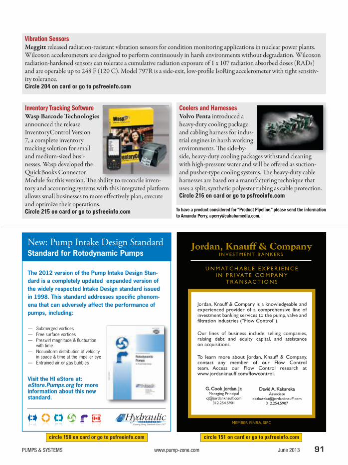
PUMPS & SYSTEMS www.pump-zone.com June 2013 91
To have a product considered for “Product Pipeline,” please send the information
to Amanda Perry, [email protected].
Inventory Tracking SoftwareWasp Barcode Technologies announced the release InventoryControl Version 7, a complete inventory tracking solution for small and medium-sized busi-nesses. Wasp developed the QuickBooks Connector Module for this version. h e ability to reconcile inven-tory and accounting systems with this integrated platform allows small businesses to more ef ectively plan, execute and optimize their operations.Circle 215 on card or go to psfreeinfo.com
Coolers and HarnessesVolvo Penta introduced a heavy-duty cooling package and cabling harness for indus-trial engines in harsh working environments. h e side-by-side, heavy-duty cooling packages withstand cleaning with high-pressure water and will be of ered as suction- and pusher-type cooling systems. h e heavy-duty cable harnesses are based on a manufacturing technique that uses a split, synthetic polyester tubing as cable protection.Circle 216 on card or go to psfreeinfo.com
bilit t il i
i h d l i
Vibration SensorsMeggitt released radiation-resistant vibration sensors for condition monitoring applications in nuclear power plants. Wilcoxon accelerometers are designed to perform continuously in harsh environments without degradation. Wilcoxon radiation-hardened sensors can tolerate a cumulative radiation exposure of 1 x 10⁷ radiation absorbed doses (RADs) and are operable up to 248 F (120 C). Model 797R is a side-exit, low-proi le IsoRing accelerometer with tight sensitiv-ity tolerance.Circle 204 on card or go to psfreeinfo.com
circle 150 on card or go to psfreeinfo.com circle 151 on card or go to psfreeinfo.com
New: Pump Intake Design StandardStandard for Rotodynamic Pumps
The 2012 version of the Pump Intake Design Stan-
dard is a completely updated expanded version of
the widely respected Intake Design standard issued
in 1998. This standard addresses specific phenom-
ena that can adversely affect the performance of
pumps, including:
— Submerged vortices
— Free surface vortices
— Preswirl magnitude & fluctuation with time
— Nonuniform distribution of velocity in space & time at the impeller eye
— Entrained air or gas bubbles
Visit the HI eStore at: eStore.Pumps.org for more information about this new standard.
U N M AT C H A B L E E X P E R I E N C E
I N P R I VAT E C O M PA N Y
T R A N S A C T I O N S
MEMBER FINRA, SIPC
Jordan, Knauff & Company is a knowledgeable and experienced provider of a comprehensive line of investment banking services to the pump, valve and filtration industries (“Flow Control”).
Our lines of business include: selling companies, raising debt and equity capital, and assistance on acquisitions.
To learn more about Jordan, Knauff & Company, contact any member of our Flow Control team. Access our Flow Control research at www.jordanknauff.com/flowcontrol.
G. Cook Jordan, Jr.Managing Principal
David A. KakarekaAssociate

92 June 2013 www.pump-zone.com PUMPS & SYSTEMS
PUMP USERS MARKETPLACE
“Serving the Pump & Rotating Equipment, Valve, and Industrial Equipment Industry since 1969”
Domestic & International
Specializing in placing:
• General Management • Engineering • Sales & Marketing • Manufacturing
DAN BOLEN • JASON SWANSON
CHRIS OSBORN • DAN MARSHALL
9741 North 90th Place, Suite 200Scottsdale, Arizona 85258-5065
(480) 767-9000 • Fax (480) 767-0100Email: [email protected]
www.danbolenassoc.com
EXECUTIVE SEARCH/RECRUITING
circle 160 on card or go to psfreeinfo.com
circle 164 on card or go to psfreeinfo.com
circle 181 on card or go to psfreeinfo.com
EMPLOYMENT
circle 158 on card or go to psfreeinfo.com
Pump Manufacturer seeks U.S. territorial repre-
sentation for the following markets, Sugar & Ethanol
Industry, Distilleries, Mining & Steel, Sewage, Water &
Waste Water, Pulp & Paper, Chemical & Petrochemical,
Irrigation, Air Conditioning HVAC, Food, Boiler Feed & Heat
Transfer, Naval and Fire Fighting & Booster Systems. For
more information, please email [email protected].
INDEX OF ADVERTISERS
Advanced Engineered Pump, Inc. 92 158
Alpha Grainger Manufacturing, Inc. 8 120
Baldor Electric Company 27 101
Bartlett Bearing Company 51 121
Benshaw Incorporated 33 122
BLACOH Fluid Control, Inc. 41 139
Blue-White Industries 11 124
Conhagen 53 154
Continental Pump Company 94 159
Cornell Pump Company 77 140
Dan Bolen & Associates, LLC 92 160
Denmar Pump Services, Inc. 54 142
Environmental Gasket Co., Ltd. 59 143
Equipump 95 161
Flowrox Inc. 7 125
Frost & Sullivan 78 156
Graphite Metallizing Corp. 58 149
Grundfos Pump Corp. BC 102
Houston Dynamic Service, Inc. 93 163
Hydraulic Institute 91 150
Hydro, Inc. 92 181
Hydro, Inc. IFC 100
Hyundai Heavy Industries Co. Ltd. 31 104
ICR Water Technologies Inc. 92 164
InfoSight 30 144
InfoSight 94 157
John Crane 55 118
Jordan, Knauff & Company 91 151
Junty International, Ltd. 95 165
KB Electronics, Inc. 35 145
KSB, Inc. 63 126
LE 12 127
LE 93 167
Load Controls, Inc. 26 128
Load Controls, Inc. 95 168
LobePro 94 162
Maag Automatik Inc. 58 152
Magnatex Pumps, Inc. 94 169
Master Bond Inc. 94 170
Meltric Corporation 93 171
Motion Industries 37 105
Mouvex 14 129
National Pump Company 19 130
NETZSCH, Group 23 131
Nidec Motor Corporation 47 106
NSK 25 132
O’Drill MCM/Titan Pumps 53 153
Orion Seals 46 141
Phoenix Contact 15 107
Pioneer Pump 17 133
Pump Solutions Group 69 146
PumpWorks 610 13 123
Scenic Precise Element Inc. 95 172
Schenck Trebel Corp. 21 134
Schlumberger 5 108
Schneider Electric Webinar 79 109
SEPCO 61 135
SEPCO 94 173
Sims Pump Co. 65 110
Sims Pump Co. 95 174
Singer Valve, Inc. 78 155
SJE-Rhombus 34 147
Skinner Power Systems, LLC 18 136
TECO-Westinghouse 67 119
ThinQk Ltd. 93 175
Toshiba 49 117
Trachte, USA 93 176
Tuf-Lok International 93 177
United Rentals, Inc. 9 111
Varisco USA Inc. 93 178
Vaughan 3 112
Vertil o Pump Company 93 179
Vesco 95 180
Viking 45 138
Vogelsang USA 36 148
WEFTEC 75 113
WEG Electric Corporation 39 114
Wilden 22 137
Xylem USA IBC 115
Yaskawa America, Inc. 43 116
* The Index of Advertisers is furnished as a courtesy, and no respon-sibility is assumed for incorrect information.
Advertiser Name Page RS# Advertiser Name Page RS#

PUMPS & SYSTEMS www.pump-zone.com June 2013 93
meltric.com
800.433.7642
� Connector + Switch in 1 device� Maximizes Arc Flash Protection� Minimizes PPE Requirements
PUMPPLUGS
QUICKLY CONNECT
& DISCONNECT POWER
Safety Shutter(on receptacle)
OFF Button
Rated up to 200A, 60hp
circle 178 on card or go to psfreeinfo.com
circle 163 on card or go to psfreeinfo.com
circle 171 on card or go to psfreeinfo.com
Rotating Equipment Repair Specialists
Rotating/Centrifugal Pumps | Turbines | Compressors
Fan & Blowers | Gears/Gear Boxes | Centrifuges
P 713.928.6200 | F 713.928.9203 | 8150 Lawndale, Houston, TX 77021
www.houstondynamic.com
www.thinqk.com
AFTERMARKET PARTS
AIR OPERATED DIAPHRAGM PUMPS
YOUR AVERAGE
SAVINGS 25%circle 175 on card or go to psfreeinfo.com
www.lt-eng.com/products/vertical-hollow-shaft
Primarily designed for deep well turbine pump applications.
• Unmatched reliability
• Cost-ef ective
• 30% more ei cient
• Easy to install
XEMC VERTICAL HOLLOW-SHAFT MOTORS
circle 167 on card or go to psfreeinfo.com circle 179 on card or go to psfreeinfo.com
circle 176 on card or go to psfreeinfo.com
circle 177 on card or go to psfreeinfo.com

94 June 2013 www.pump-zone.com PUMPS & SYSTEMS
PUMP USERS MARKETPLACE
circle 159 on card or go to psfreeinfo.com
circle 169 on card or go to psfreeinfo.com
circle 173 on card or go to psfreeinfo.com
ROTARY LOBE SLUDGE PUMPS FOR SLUDGES/SLURRIES/CORROSIVES
912-466-0304 www.LOBEPRO.com Made in USA
MPS
LURRIES/CORROSIVES
Self Priming to 25”.
Reversible operation.
Cartridge seals for quick replacement. No pressure bottle needed below 100 psi.
In Place wear part replacement at 1/3 the cost and time for equivalent screw (PC) pump.
To learn more or get a custom quote, email [email protected]
circle 162 on card or go to psfreeinfo.com
www.masterbond.com
Hackensack, NJ 07601 USA
+1.201.343.8983 [email protected]
Epoxy Polysulfide FLEXIBLE
EP21TP-2EP21TP-2
Chemically resistant
Withstands thermal cycling
Excellent sealant
circle 157 on card or go to psfreeinfo.com
circle 170 on card or go to psfreeinfo.com

PUMPS & SYSTEMS www.pump-zone.com June 2013 95
MONITOR PUMP PERFORMANCE
circle 174 on card or go to psfreeinfo.com
circle 172 on card or go to psfreeinfo.com
circle 168 on card or go to psfreeinfo.com
circle 161 on card or go to psfreeinfo.com
circle 165 on card or go to psfreeinfo.com
Solvedry start
problems withVesconite Hilube
bushings� Increase MTBR� No swell� Low friction = reduced
electricity costs� Quick supply.
No quantity too small
Tollfree [email protected]
www.vesconite.com
circle 180 on card or go to psfreeinfo.com
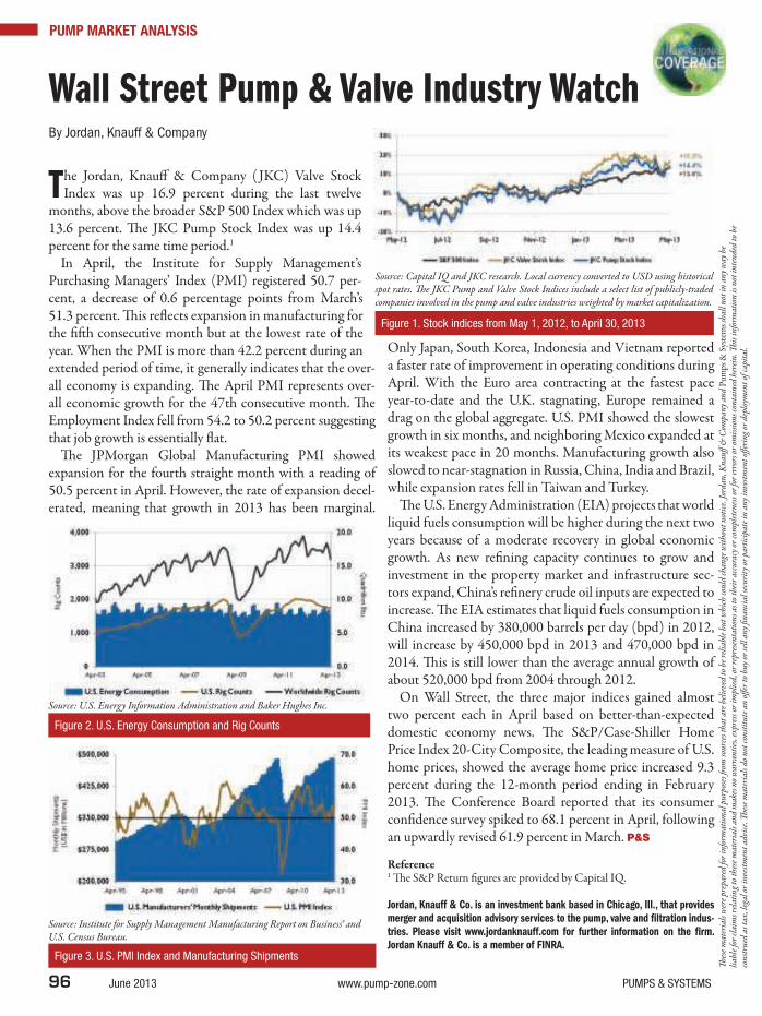
96 June 2013 www.pump-zone.com PUMPS & SYSTEMS
PUMP MARKET ANALYSIS
Wall Street Pump & Valve Industry WatchBy Jordan, Knauff & Company
The Jordan, Knauf & Company ( JKC) Valve Stock Index was up 16.9 percent during the last twelve
months, above the broader S&P 500 Index which was up 13.6 percent. h e JKC Pump Stock Index was up 14.4 percent for the same time period.1
In April, the Institute for Supply Management’s Purchasing Managers’ Index (PMI) registered 50.7 per-cent, a decrease of 0.6 percentage points from March’s 51.3 percent. h is rel ects expansion in manufacturing for the i t h consecutive month but at the lowest rate of the year. When the PMI is more than 42.2 percent during an extended period of time, it generally indicates that the over-all economy is expanding. h e April PMI represents over-all economic growth for the 47th consecutive month. h e Employment Index fell from 54.2 to 50.2 percent suggesting that job growth is essentially l at.
h e JPMorgan Global Manufacturing PMI showed expansion for the fourth straight month with a reading of 50.5 percent in April. However, the rate of expansion decel-erated, meaning that growth in 2013 has been marginal.
Only Japan, South Korea, Indonesia and Vietnam reported a faster rate of improvement in operating conditions during April. With the Euro area contracting at the fastest pace year-to-date and the U.K. stagnating, Europe remained a drag on the global aggregate. U.S. PMI showed the slowest growth in six months, and neighboring Mexico expanded at its weakest pace in 20 months. Manufacturing growth also slowed to near-stagnation in Russia, China, India and Brazil, while expansion rates fell in Taiwan and Turkey.
h e U.S. Energy Administration (EIA) projects that world liquid fuels consumption will be higher during the next two years because of a moderate recovery in global economic growth. As new rei ning capacity continues to grow and investment in the property market and infrastructure sec-tors expand, China’s rei nery crude oil inputs are expected to increase. h e EIA estimates that liquid fuels consumption in China increased by 380,000 barrels per day (bpd) in 2012, will increase by 450,000 bpd in 2013 and 470,000 bpd in 2014. h is is still lower than the average annual growth of about 520,000 bpd from 2004 through 2012.
On Wall Street, the three major indices gained almost two percent each in April based on better-than-expected domestic economy news. h e S&P/Case-Shiller Home Price Index 20-City Composite, the leading measure of U.S. home prices, showed the average home price increased 9.3 percent during the 12-month period ending in February 2013. h e Conference Board reported that its consumer coni dence survey spiked to 68.1 percent in April, following an upwardly revised 61.9 percent in March. P&S
Reference1 h e S&P Return i gures are provided by Capital IQ.
Jordan, Knauff & Co. is an investment bank based in Chicago, Ill., that provides
merger and acquisition advisory services to the pump, valve and i ltration indus-
tries. Please visit www.jordanknauff.com for further information on the i rm.
Jordan Knauff & Co. is a member of FINRA.
Figure 2. U.S. Energy Consumption and Rig Counts
Figure 3. U.S. PMI Index and Manufacturing Shipments
Source: U.S. Energy Information Administration and Baker Hughes Inc.
Source: Institute for Supply Management Manufacturing Report on Business® and U.S. Census Bureau.
Figure 1. Stock indices from May 1, 2012, to April 30, 2013
Source: Capital IQ and JKC research. Local currency converted to USD using historical spot rates. h e JKC Pump and Valve Stock Indices include a select list of publicly-traded companies involved in the pump and valve industries weighted by market capitalization.
h es
e m
ater
ials
wer
e pr
epar
ed fo
r in
form
atio
nal p
urpo
ses r
om
sour
ces t
hat a
re b
elie
ved
to b
e re
liab
le b
ut w
hich
coul
d ch
ange
wit
hout
not
ice.
Jord
an, K
nauf
& C
ompa
ny a
nd P
umps
& S
yste
ms
shal
l not
in a
ny w
ay b
e li
able
for
clai
ms r
elat
ing
to th
ese
mat
eria
ls a
nd m
akes
no
war
rant
ies,
expr
ess o
r im
plie
d, o
r re
pres
enta
tion
s as t
o th
eir
accu
racy
or
com
plet
enes
s or
for
erro
rs o
r om
issi
ons c
onta
ined
her
ein.
h i
s inf
orm
atio
n is
not
inte
nded
to b
e co
nstr
ued
as ta
x, le
gal o
r in
vest
men
t adv
ice.
h e
se m
ater
ials
do
not c
onst
itut
e an
of e
r to
buy
or
sell
any
i nan
cial
secu
rity
or
part
icip
ate
in a
ny in
vest
men
t of e
ring
or
depl
oym
ent o
f cap
ital
.

TotalCare servicesFor secure, optimal operations
Xylem TotalCare is a comprehensive, integrated portfolio of
services that ensures your business keeps running at its best.
Our portfolio comes backed by deep systems knowledge
and expertise in water and wastewater applications. Which
gives you the operational security and more time to focus
on your core business.
What can Xylem do for you?
Call 1 704 409–9700 or visit
www.xylemtotalcare.com
For more information visit booth #6000 at ACE13
circle 115 on card or go to psfreeinfo.com

Hydro MPC:Perfecting your energy responsibility
b.com/GrundfosPumpUSA
twitter.com/GrundfosUSA
youtube.com/GrundfosUSA
www.grundfos.us
SimplifyIntegrateOptimize
circle 102 on card or go to psfreeinfo.com