June, 15 2008 Robert Karban representing the SE^2 …mbse.gfse.de › documents ›...
38
Telescope systems modelling June, 15 th 2008 Robert Karban representing the SE^2 team
Transcript of June, 15 2008 Robert Karban representing the SE^2 …mbse.gfse.de › documents ›...
Telescope systems modelling
June, 15th 2008Robert Karban
representing the SE^2 team

About SE^2
• Collaboration between the European Southern Observatory (ESO) and German Chapter of INCOSE (GfSE)
• Access to a high-tech project, the Active Phasing Experiment (APE).
• The team members are:– Robert Karban (ESO)– Andreas Peukert (TU Munich)– Tim Weilkiens (oose) – Rudolf Hauber (HOOD)
Presented to the INCOSE 2008 Symposium page 2
Presenter
Presentation Notes
The SE^2 team is a collaboration between the European Southern Observatory (ESO) and the SysML working group of the German Chapter of INCOSE (GfSE) ESO provides access to one of its high-tech projects funded by the European Union, the Active Phasing Experiment (APE). The team members are geographically distributed with different technological background (Astronomy, Astronautics, Aerospace, Defence). �The core team consists of: Robert Karban (ESO) – team leader Andreas Peukert (TU Munich) Tim Weilkiens (oose) Rudolf Hauber (HOOD)
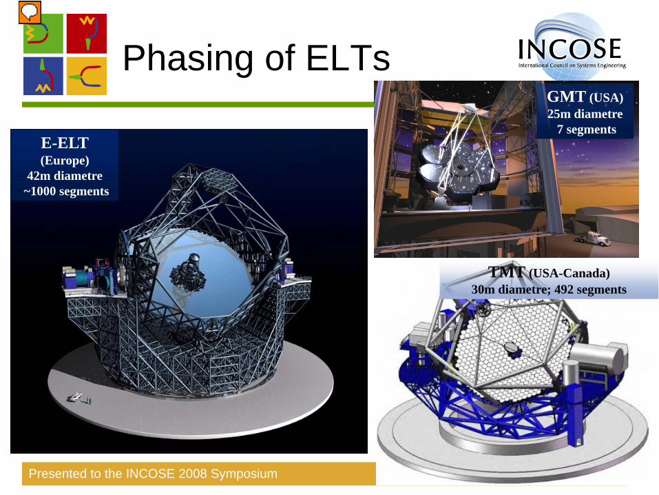
Phasing of ELTs
Presented to the INCOSE 2008 Symposium page 3
TMT (USA-Canada)30m diametre; 492 segments
GMT (USA)25m diametre
7 segmentsE-ELT(Europe)
42m diametre~1000 segments
Presenter
Presentation Notes
The goal of the next generation of telescopes is to collect much more light. Therefore very big mirrors are required which cannot be made any longer of one single piece. The drawing shows a draft of the mechanical structure of the European Extremely Large Telescope (E-ELT) and its competitors, the GMT and TMT. The E-ELLT will be about 70m wide, where the primary mirror is 42m in diameter. In order to have a 42 meter diameter mirror, the mirror is segmented in hexagonal pieces of about 1.5 diameter each. This results in about 1000 hexagonal segments. Due to different disturbances (vibrations, wind, gravity etc.) the segments must be actively controlled to get a continuous mirror surface with an accuracy of a few nanometres.
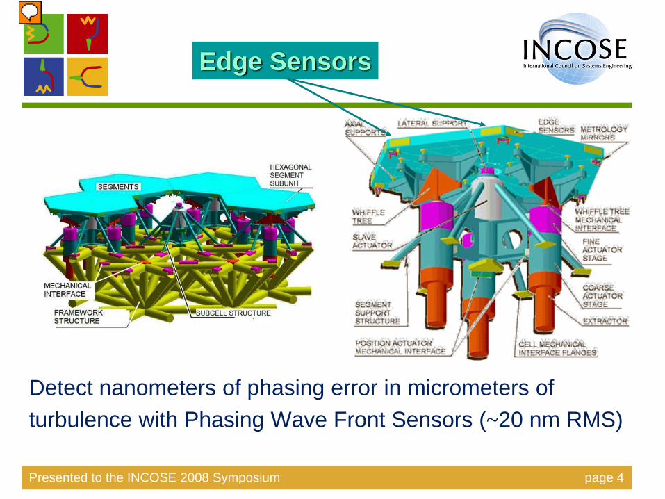
Detect nanometers of phasing error in micrometers ofturbulence with Phasing Wave Front Sensors (~20 nm RMS)
Presented to the INCOSE 2008 Symposium page 4
Edge Sensors
Presenter
Presentation Notes
The wave front is distorted by various factors: one of them is a wrong positioning of the segments of the primary mirror which will result in a discontinuous surface. This is compensated by the so-called phasing loop. The main challenge is to correctly detect the positioning errors of the segments with specific sensors in order to bring the surface of the primary mirror close to the one of a monolithic mirror. Edge Sensors are used to measure the position of the segments relative to each other at a closed loop of about 1Khz. Before the this loop can be closed the edge sensors must calibrated, which happens periodically. This calibration is carried out by so-called phasing sensors.

Phasing of ELTs and APE
Presented to the INCOSE 2008 Symposium page 5
Courtesy of F. Gonte
Presenter
Presentation Notes
The Active Phasing Experiment (APE) represents a technology evaluation breadboard for large telescopes. The essential purpose of the APE experiment is to explore, integrate, and validate active wave front control schemes and different phasing sensor technologies for a European Extremely Large Telescope (EELT). This includes the evaluation and comparison of the performance of different types of wave front sensors in the laboratory and on the sky on the one hand, and the integration of the control of a segmented aperture control into an already existing active system and driving both the active system and the control of the segments on the other hand. APE is close to completion and deployment in an operational environment. APE will be deployed in the lab, standalone, but also in an already existing telescope. It contains an active segmented mirror (ASM) with 61 hexagonal elements of 1.2cm in diameter which can be controlled the same way as the future E-ELT primary mirror. The ASM can be controlled in piston (movement perpendicular to surface), tip and tilt (rotations about x/y, parallel to surface). To evaluate the sensors capabilities a special metrology system is built (the Internal Metrology). Based on interferometric measurements, it provides high accuracy (5 nanometers) to determine the exact position of the segments in piston, tip and tilt and simulate the edge sensors of the E-ELT.

Very Large Telescope
Presented to the INCOSE 2008 Symposium page 6
APE will be installed at the telescope in the Chile desert.
Presenter
Presentation Notes
To properly evaluate the sensors, APE will be installed on an existing telescope in order to work with real stars. It will be installed on one of the VLT telescopes in Chile which belongs to the 8m class telescopes. It is installed as a normal instrument on one of the so called Nasmyth platforms, indicated by the little man on the middle-right of the schematic drawing. It has to comply with various mechanical, electrical, optical and software interface specifications for this installation.

The APE project
Presented to the INCOSE 2008 Symposium page 7
Presenter
Presentation Notes
The major challenge for SysML is to add value for systems engineering of interdisciplinary projects. For the demonstration of the feasibility of using SysML during the systems engineering process of real-world complex systems, such a system shall be modeled. APE, a project of ESO, is chosen as a case study which fulfills these aspects. The main objectives of APE are shown in a requirements diagram. Why are we modeling requirements and not only use DOORS? Benefit of modeling requirements are: One central repository for system engineering. Visualization of key requirements Clustering of coherent requirements (use cases) Visualization key requirements impact on design and test

System Overview
Presented to the INCOSE 2008 Symposium page 8
Presenter
Presentation Notes
The Project Content diagram shows all different aspects and models needed to describe a system. APE, as any complex system, has a large number of functional, performance, physical and interface requirements which have to be satisfied. This implies the need for a professional requirements engineering and management during the project. This is the first application of SysML during the development. APE has about 50 high-level system requirements. The control system has also about 50 requirements, complemented by 150 Use Cases. APE consists of various elements, like wheels, translation stages, lenses, detectors, (segmented) mirrors, light sources, an interferometer, sensors and actuators (19 small axes, 10 TCCDs, 11 other devices, 183 actuators for segmented mirror). The control system alone consists of 12 computing nodes. These elements offer all kinds of optical, mechanical, electronic and software interfaces, both system internal and external to other systems. Their management alone is very challenging for the systems engineering team. Besides these challenges, which apply for many complex systems, APE has some other aspects: The most noticeable challenge of APE is the highly demanding optical layout, which is a unique challenge for every optical system. The highly sensitive system requires a consistent coordinate system of the various parts to ensure a correct optical path. Apart from this it also challenges the control, since there are several open and closed loop systems required. A significant amount of data is produced by image processing data flows. Since APE will be deployed in the lab and in an already existing telescope, slightly different functional aspects are active depending on the deployment mode. Therefore different interfaces to existing systems are needed.
SE^2 goals
Presented to the INCOSE 2008 Symposium page 9
• Provide examples of SysML, common modelling problems and approaches:
Build a comprehensive model of the system APE and additional supporting models as elaborate example for all three aspects
• Provide guidelines for modelling a system with SysML resulting from experiences during project
Establish a modelling FAQ to support consistent modelling results (for this and future projects)
• Demonstrate that SysML is an effective means to define common concepts
• Demonstrate that a SysML model enhances traceability
What have we been able to achieve?
Presenter
Presentation Notes
Provide examples of SysML, common modelling problems and approaches Build a comprehensive model which serves as the basis for providing different views to different engineering aspects (e.g. system, logical, mechanical, control) and subsequent activities of analysis and design alike. Demonstrate that SysML is an effective means to define common concepts (requirement types, interfaces, relationships, etc). Demonstrate that a SysML model enhances traceability between requirements, design and verification/validation. The actual benefit for the APE project is an improved documentation by using diagrams in new releases of documents, related papers and presentations for clearer communication.

Deliverables:Modelling FAQ
• (Exemplary) content of modelling FAQ:– Identification of necessary system models, aspects and views– Guidelines for the use of modelling elements (e.g. use of ports
and flows)– Guidelines for interface modelling– Allocation strategies– Guidelines for modeling the system structure– Guidelines for the definition of system hierarchies– Heuristics for using requirements relationships (e.g. derive, refine)– Naming conventions for modelling elements (e.g. diagram names,
block names)– Style and layout issues
Presented to the INCOSE 2008 Symposium page 10
Presenter
Presentation Notes
A modeling FAQ which answers questions that turned up during the project. Guidelines for the use of ports and flows for various types of interfaces Allocation strategies. What can be allocated to what and how? Guidelines for the definition of system hierarchies: e.g. differentiation between logically grouped (sub)systems with abstract interfaces VS. concrete components with real interfaces e.g. modeling of connectors crossing several levels of a system hierarchy Heuristics for using the requirements relationships. They are not defined in a mathematical sense and their application is sometimes not clear. Naming conventions A scalable model structure and organization defining requirements, structure with interfaces and behavior. An analysis model, using parametrics The FAQ is extracted from the blog of activities, decisions and discussions which occurred during modeling.

Deliverables:System model
• Three major model parts:– Actual system model: APE (with all mentioned system aspects)– Catalogue model: standard parts, library of block prototypes– Modelling profile: additional stereotypes
• Main characteristics:– Scalable model structure and organisation – Includes model annotations, external references– Various examples of ports and flows to model interfaces
• Abstraction levels– Functional, Structural, Deployment
• Preliminary results are available at mbse.sysmod.de
Presented to the INCOSE 2008 Symposium page 11
Presenter
Presentation Notes
The project is modeled in different aspects, each serving a particular purpose: Requirements, Context, Structure, Behavior, Data, Verification and Performance This very same structure is recursively used for all its major sub systems which allows rather self-contained packages covering all aspects. This is in particular important for sub-contracting complete sub systems and organize the system development. The Context defines the scope of the system and its interfaces with its environment. Requirements for each sub-system are derived from system requirements, which refine user requirements which in turn are traced to Objectives. The Structure is organized according to the product tree. As interface are the basic element of an architecture it is very important to have a reduced picture of an interface (not only a CAD drawing). A significant effort was spent to define different variants, depending on the modeling goal. In particular the consistent modeling of logical, mechanical interfaces and their related flows. Often the parts of a system come from some kind of catalogue (like motors, connectors, etc.) which are used to build the system. They might have different usages in different contexts. Domain specific value types are defined in a separate package. New Modeling elements (stereotypes) are kept in a separate profile for re-use. Behavior is mainly described with activity diagrams where call-behavior actions are used at every abstraction level of the system. In general there are only 2 abstraction levels – functional and structure and allocating function to structure. No explicit logical structure is needed – the functional view is sufficient. The same applies for control system but there exists an additional deployment level for allocation of SW components to HW components. For the Performance model only a concept for modeling the optical error budget is ready. It is to be completed.

Solution:System model
Presented to the INCOSE 2008 Symposium page 12
Example for system context
3 modeling approaches for interfaces
Presenter
Presentation Notes
The System context is modelled using IBDs. Our main focus is on system interfaces. Three different possibilities are shown to model an interface Combination of mechanical and flow interface at block level (Model physical and logical properties at border of block without opening it.) Mechanical and flow interface at part level Mechanical and flow interface at block and part level. Abstract interface representing and ICD (using standard ports). Problem is ensuring consistency between ICD document and the model which is used to create the ICD.

System model:High Level Structure
Presented to the INCOSE 2008 Symposium page 13
Example for system structure: “Product tree” of Opto-Mechanical Bench
Presenter
Presentation Notes
Complex models tend to become very quick confusing. A good model structure is the key to keep the model understandable. Our structure is based on product tree. The product tree is defined by a BDD.

System model: Detailed Structure
Presented to the INCOSE 2008 Symposium page 14
Example for refined system structure:“Optical view of APE”
Presenter
Presentation Notes
A model is much more than just a couple of diagrams. A model consists of multiple views showing different aspects of the system that are interconnected. The same components can be connected in different views in different ways. This diagrams shows the optical layout in an abstract manner.
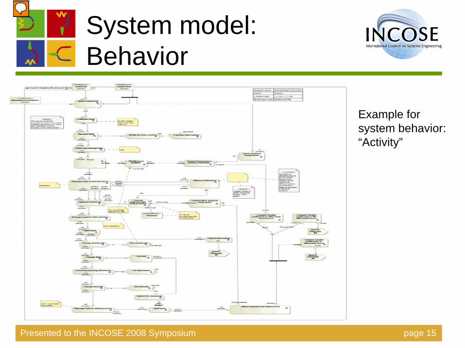
System model: Behavior
Presented to the INCOSE 2008 Symposium page 15
Example for system behavior:“Activity”
Presenter
Presentation Notes
The model shows at the same time the physical effect of a system (like distortion of wave front) as well as sensing, actuating actions and control flows.

Catalogue model:Abstract types
Presented to the INCOSE 2008 Symposium page 16
Example for catalogue:
Presenter
Presentation Notes
Abstract types are used as place holder for specific building blocks. They are classified in different packages.

Catalogue model:Concrete types
Presented to the INCOSE 2008 Symposium page 17
Example for catalogue:Power Supply Interfaces
Presenter
Presentation Notes
Catalogues can be easily extended by using inheritance. Furthermore the preliminary design of a system can work with an abstract type (when the detailed requirements are yet unknown) and decide later which specific type to use for the implementation. Standards are defined by value properties which can be redefined.

Catalogue model:Type usage
Presented to the INCOSE 2008 Symposium page 18
Example for catalogue:CPU types and different flow port assignments
Presenter
Presentation Notes
Different use of parts in different contexts (different items flow over the same type of connector). Here a 96 pin connector has a different assignment. A generic connector gets a different context specific assignment by inheritance. For each specific assignment a separate specialization is needed.

Catalogue model:Assembling the pieces
Presented to the INCOSE 2008 Symposium page 19
Example for a complex catalogue part, a TCCD
Presenter
Presentation Notes
Model cables using blocks or association blocks.
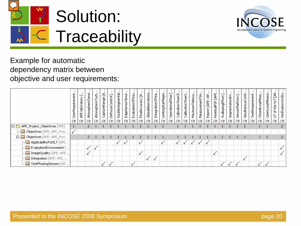
Solution:Traceability
Presented to the INCOSE 2008 Symposium page 20
Example for automatic dependency matrix between objective and user requirements:
Presenter
Presentation Notes
Completeness of traceability can be checked by automatically creating dependency matrices.

Solution:Modelling profile
Presented to the INCOSE 2008 Symposium page 21
Example for SE^2 profile:
Presenter
Presentation Notes
The SE^2 profile extends the SysML by adding stereotypes for different connectors (optical, mechanical), specific block types (Software, Electronics).

SysML challenges
• Combining different aspects with Nested ports• Variant modeling• Property specific types• Different types of interfaces like mechanical,
electrical, logical, interface based on a standard document
• Reuse of association blocks• Defining QoS• Multi-layer abstraction (like ISO OSI model)• Mapping activities to blocks
Presenter
Presentation Notes
Mapping of Pins/Parameters of Actions/Activities and Object nodes in activity diagrams to ports and item flows in IBDs: It is unclear how they should be mapped properly. Is there a 1:1 mapping from object nodes to item flows and Pins to Ports?

Challenge:Nested Ports
Presented to the INCOSE 2008 Symposium page 23
Example for nested ports:
Presenter
Presentation Notes
By using complex ports, the cable is a standard port with standard sub ports which represent both ends of the cable. This is particular useful when a cable is permanently soldered to a chip, like here to a CCD head PCB. Complex ports have proven to be very useful if different interface properties shall be shown at the same time: Mechanical interface and protocol (e.g. RJ45 and Ethernet) Different Assignments of Pins on a plug (96 VME pin has vendor specific pin assignments, like serial or Ethernet) Modeling interfaces and logical channels Bundling port types, like grouping all electrical flows into one port. Model cables using nested ports.

Challenge: Variant modeling
Presented to the INCOSE 2008 Symposium page 24
Different contexts imply different design
Presenter
Presentation Notes
Variant modeling: There is an open issue with variants. APE has two variants, represented by different contexts (Lab and Telescope). Depending on the context different parts must be used which are deeply nested in the product tree (e.g. Support structure in the lab and support structure on the telescope). The problem is how to relate this information, i.e. how do you model that those parts are depending on the context? The current approach is to use inheritance and add a comment. But it is difficult to identify all variant depending parts. Maybe the SysML view could help?

Challenge: Property specific types
Presented to the INCOSE 2008 Symposium page 25
Electrical connectors with different genders and suppliers
Presenter
Presentation Notes
Properties, in particular value properties, need to have different values depending on the use. Especially when blocks are re-used (like catalog parts) certain properties need different values. Like gender of connectors, pressure of air, diameters of wheels and screws, etc. Property specific types are very difficult to use because instances and default values have to be used. This has two major drawbacks: First it requires much manual modeling work (too many clicks !). Second, it requires a manual consistency check if values have to be changed. Property specific values cannot be assigned on types of ports since they do not exist as property. They can only be defined for part properties. We cannot specify the gender of a port with it.

Challenge: Interfaces specified by ICDs
Presented to the INCOSE 2008 Symposium page 26
ICD specifies the APE-Telescope interface
Presenter
Presentation Notes
Standard ports (not flow ports!) are used to describe interfaces between system that are defined in an Interface Control Document.

Challenge: Re-use of association blocks
Presented to the INCOSE 2008 Symposium page 27
Cables in a part catalogue
Presenter
Presentation Notes
This is an association class stereotyped block to make it an association block. In the model it appears as a Relation in the Cables packages in "Relations". This association block is an association between these two block types. It canNOT be reused for another association. Only the association and its blocks as a whole can be re-used. This also means that this block cannot exist without the association, which would not be true for many such blocks in real life (e.g. a cable can exist without being connected). This means the same block (e.g. cable) cannot be used within the model to represent an electrical AND a mechanical connection between two blocks in two different diagrams. N.B. Association between generalized blocks are not seen in their specializations. An association block is a specific association between two types. Cables modeled with association blocks cannot be reused alone. Reuse can only be achieved by inheritance.

Challenge: Re-use of blocks
Presented to the INCOSE 2008 Symposium page 28
Presenter
Presentation Notes
Reuse of block can only occur through inheritance. In this example for every crate configuration a separate block has to be created. This blocks are then “instantiated” as part properties. The LCUCrate block cannot be used as part property directly, adding CPU boards, because then ALL CPU boards would become a property of this block.
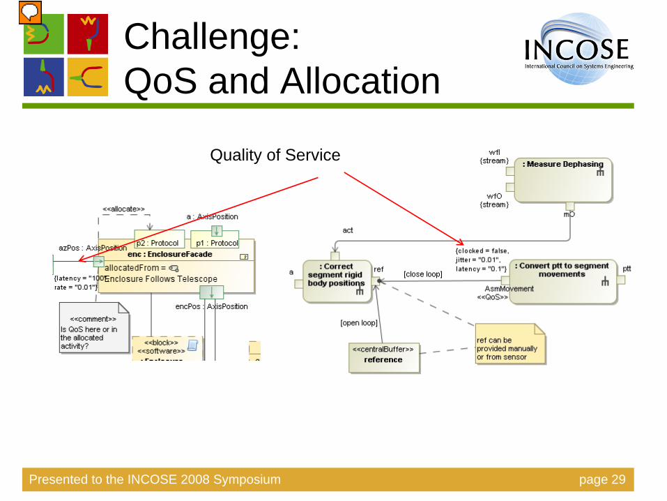
Challenge:QoS and Allocation
Presented to the INCOSE 2008 Symposium page 29
Quality of Service
Presenter
Presentation Notes
Defining QoS: How/Where should we define QoS of flows, in particular data flows? On the Pin, Parameter, Parameter node or on the flow port? The type of a flow port (be it atomic or not) defines what flows over it. How/Where shall we define e.g. synchronization, latency, jitter, throughput? They look more like requirements on the design, satisfied by QoS of a certain implementation, like DDS, CORBA. They are usually derived requirements from a higher level activity diagram. How shall it be related? N.B.: the two diagrams come from different examples and are not consistent.
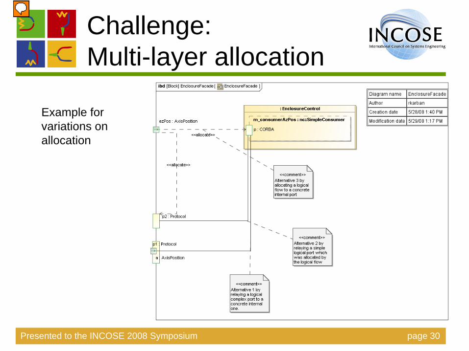
Challenge:Multi-layer allocation
Presented to the INCOSE 2008 Symposium page 30
Example for variations on allocation
Presenter
Presentation Notes
Multi-layer abstraction based on ISO OSI: Allocating a flow port (logical) to standard port (representing the abstract protocol) and internally allocating it to a concrete protocol Using complex ports to represent logical flow using a protocol ISO OSI Physical layer (electrical and physical specifications for devices, layout of pins, voltages, cable specifications, Hubs, repeaters, etc.) Data Link layer (functional and procedural means to transfer data between network entities) Network layer (functional and procedural means of transferring variable length data sequences from a source to a destination via one or more networks) Transport layer (tcp, udp) Session layer Presentation layer Application layer (CORBA, DDS)
Challenge:The Tool
• Formal implementation of standards• Navigation through the model• Printer size friendly diagrams• Tables and matrices as input and output
medium• Support• Documentation, Examples• Performance
Presenter
Presentation Notes
More formality avoids wrong application of SysML and would kill unambiguous communication of information. Navigation: There is an open issue about navigation to the different views of a block (mechanical, optical, ...). Each view is represented by an IBD. Different views exist for the same block i.e. IBDs for optical, mechanical, etc. What’s the best way to see that a block has different views and to navigate there?

Configuration management approach
• SVN repository for native model files• Partial packaging of (system) model segments into
separate modules (=files)Only partially successful, some arising consistency
problems• Trial of Teamwork Server
Inflexible integration with SVNNot tested enough yet to give conclusion
Very tool dependentFind out who changes what, where and when?
Presented to the INCOSE 2008 Symposium page 32
Presenter
Presentation Notes
Difficulties in tracing changes on element level. In MD only by model comparison. Would be nice to have a track changes system like in Word processors.
Tools and environment
• MagicDraw 15.1, SysML plugin 15.1• Subversion, MD Team work server• Windows PC• Wiki for team communication• E-Mail, phone and face to face meetings• Limited time resources of all team
members
Presented to the INCOSE 2008 Symposium page 33

Any other business
• MBSE practices used– 6 system views [Maier, Rechtin]
• Degree of execution– No such modeling tool capability– No need for risk reduction
• Model interchange capabilities– Not tried
• Training material– Navigable online model– List of Frequently Asked Questions
Presented to the INCOSE 2008 Symposium page 34
Presenter
Presentation Notes
Executable model reduce risk in early phases of the project. The main task for SE^2 is reverse engineering risk reduction is not an issue.
MBSE metrics
• Resource usage (1.12.2007 – 9.6.2008)– four persons– about 60h administration– about 150h modeling
• Model– about 13000 model elements– about 700 symbols– about 150 diagrams
Presented to the INCOSE 2008 Symposium page 35
MBSE findings, issues, and recommendations
• Modeling mentor• Modeling recipes• Modeling task force• Guidelines for modeling - templates• Guidelines for application of the tool• Layout standards• Model only as much as needed to
understand the systemPresented to the INCOSE 2008 Symposium page 36
Presenter
Presentation Notes
A modeling mentor is indispensible Define modeling recipe for particular problem Task force creates a first base line Establish modeling guidelines (FAQ), otherwise you get only a set of inconsistent diagrams and enforce them by templates built-into the tool. Setup guidelines for application of the tool Layout standards: Integration in documents and visualization on screen becomes difficult without layout standards, like a maximum diagram size (e.g. A4). Model only as much as needed to understand the system. Modeling is not an end in itself!

Plan forward
• Elaborate linking among different aspects • Add more and more details in depth
(system, subsystem, assembly, …)• Logical vs. Physical hierarchies• Multi-layer allocations, QoS, Reuse• Transition SysML -> UML for software
intensive systems
Presented to the INCOSE 2008 Symposium page 37
Presenter
Presentation Notes
Logical vs. Physical hierarchies There is an ongoing discussion about using the composition relationship for logical and/or physical hierarchies. The composition relationship is mostly used to model a physical hierarchy, not a logical hierarchy. e.g. is a cable in a crate part of the crate or not? Different views are very helpful to understand the way the system works. For example Internal Metrology: PhaseModulator and SignalDecoder are much more logical subsystems residing in the physical crate. They are modeled it according to this logical decomposition and therefore there are interfaces between PhaseModulator and SignalDecoder. From a physical point of view these interfaces may seem very "strange", because the light beam just runs through a number of mirrors. All this might be related to the re-use problem, mentioned in previous slides. Elaborate linking among different aspects: requirements, structure, verification, data model and behavior Add more and more details in depth (system, subsystem, assembly, …) Transition SysML -> UML: find the best way to map a SysML block, representing SW to one or more classes, components.

Acknowledgements
• Sandy Friedenthal• Dr. Darren Kelly
Presented to the INCOSE 2008 Symposium page 38