Junction configuration-induced mechanisms govern elastic and … · 2019-04-03 · Junction...
11
Junction configuration-induced mechanisms govern elastic and inelastic deformations in hybrid carbon nanomaterials Rouzbeh Shahsavari a, b, c, * , Navid Sakhavand a a Department of Civil and Environmental Engineering, Rice University, Houston, TX 77005, USA b Department of Material Science and NanoEngineering, Rice University, Houston, TX 77005, USA c Smalley Institute for Nanoscale Science and Technology, USA article info Article history: Received 12 May 2015 Received in revised form 11 August 2015 Accepted 28 August 2015 Available online 4 September 2015 abstract Although various hybrid 3D carbon-based architectures are reported by covalently connecting low dimensional carbon allotropes, the effect of junction configuration on deformation and mechanical properties of the hybrid carbon architectures remain elusive. Here, we focus on Pillared Graphene Nanostructure (PGN) as a model system with symmetric and asymmetric junctions to explore its diverse elastic and inelastic properties via first-principles and molecular dynamics simulations. By introducing heptagonal and octagonal rings in the junctions, our findings demonstrate that in contrast to the stacked of graphene sheets, which exhibit weak out-of-plane properties, both junction types impart a cooper- ative two-regime deformation mechanism that provides a number of superior characteristics in PGN, including 3D balance of strength and toughness as well as an outstanding ~42% out-of-plane ductility preceding the failure. Furthermore, asymmetric junctions impose wrinkles in the PGN sheets, which add extra in-plane flexibility and shear compliance, result in a nearly zero/negative in-plane Poisson's ratio in PGN, and cause the octagonal rings to act as hotspot for initiating of fracture. Our results provide the first atomistic “lens” on fundamental understanding of junction-induced deformation mechanisms in pillared graphene and can potentially provide a new phase space to better control and design mechano-mutable hybrid carbon nanostructures. © 2015 Elsevier Ltd. All rights reserved. 1. Introduction Low dimensional carbon-based materials such as 1-dimensional (1D) carbon nanotubes (CNTs) and 2D graphene exhibit several attractive physics and fundamental properties [1]. However, there is a high anisotropy with such 1D and 2D nanomaterials. For instance, while graphene has high in-plane stiffness (>1 TPa) and thermal conductance, owing to the strong carbonecarbon bonds [2], its out-of-plane direction stiffness and thermal conductance are considerably low, due to the weak Van der Waals forces [3]. Simi- larly, the high stiffness and thermal conductance of CNTs are limited to axial directions [4]. This restriction has stimulated re- searcher's to search and create hybrid nanomaterials that can leverage the best aspects of their constituents' and overcome the intrinsic limitations of their parent structures. Carbon nanopeapods [5e7], carbon nanobuds [8], periodic graphene nanobuds [9], nanotube-drive carbon foams [10], and pillared graphene [11] are examples of recently introduced hybrid nanostructures. Among these, Pillared Graphene Nanostructure (PGN) is a 3D structure that is created by fusing graphene sheets with carbon nanotubes via covalent bonds. Anisotropic aspects of graphene and carbon nanotubes, as 2D and 1D structures, are leveraged to confer an interesting 3D network with multifunctional properties such as high mechanical [12] and thermal [13] properties that are compa- rable to its constituents. There are several works in the literature that each has focused on certain feature(s) of PGN. For instance, Wang et al. [14] modeled nanoindentation tests along the out-of- plane direction of PGN. While their results provide insights on compressive behavior of PGN, the key benefits of PGN (to our knowledge) is in tensile stress since PGN with long tubes and flats sheets are subject to quick buckling in compression. Niu et al. [15] investigated the influence of defects such as (5577) point defects and grain boundaries on mechanical properties of PGN along the out-of-plane direction. This work only considered a single junction made of one CNT and graphene, which does not allow realizing * Corresponding author. Department of Civil and Environmental Engineering, Rice University, Houston, TX 77005, USA. E-mail address: [email protected] (R. Shahsavari). Contents lists available at ScienceDirect Carbon journal homepage: www.elsevier.com/locate/carbon http://dx.doi.org/10.1016/j.carbon.2015.08.106 0008-6223/© 2015 Elsevier Ltd. All rights reserved. Carbon 95 (2015) 699e709
Transcript of Junction configuration-induced mechanisms govern elastic and … · 2019-04-03 · Junction...
lable at ScienceDirect
Carbon 95 (2015) 699e709
Contents lists avai
Carbon
journal homepage: www.elsevier .com/locate/carbon
Junction configuration-induced mechanisms govern elastic andinelastic deformations in hybrid carbon nanomaterials
Rouzbeh Shahsavari a, b, c, *, Navid Sakhavand a
a Department of Civil and Environmental Engineering, Rice University, Houston, TX 77005, USAb Department of Material Science and NanoEngineering, Rice University, Houston, TX 77005, USAc Smalley Institute for Nanoscale Science and Technology, USA
a r t i c l e i n f o
Article history:Received 12 May 2015Received in revised form11 August 2015Accepted 28 August 2015Available online 4 September 2015
* Corresponding author. Department of Civil andRice University, Houston, TX 77005, USA.
E-mail address: [email protected] (R. Shahsavari).
http://dx.doi.org/10.1016/j.carbon.2015.08.1060008-6223/© 2015 Elsevier Ltd. All rights reserved.
a b s t r a c t
Although various hybrid 3D carbon-based architectures are reported by covalently connecting lowdimensional carbon allotropes, the effect of junction configuration on deformation and mechanicalproperties of the hybrid carbon architectures remain elusive. Here, we focus on Pillared GrapheneNanostructure (PGN) as a model system with symmetric and asymmetric junctions to explore its diverseelastic and inelastic properties via first-principles and molecular dynamics simulations. By introducingheptagonal and octagonal rings in the junctions, our findings demonstrate that in contrast to the stackedof graphene sheets, which exhibit weak out-of-plane properties, both junction types impart a cooper-ative two-regime deformation mechanism that provides a number of superior characteristics in PGN,including 3D balance of strength and toughness as well as an outstanding ~42% out-of-plane ductilitypreceding the failure. Furthermore, asymmetric junctions impose wrinkles in the PGN sheets, which addextra in-plane flexibility and shear compliance, result in a nearly zero/negative in-plane Poisson's ratio inPGN, and cause the octagonal rings to act as hotspot for initiating of fracture. Our results provide the firstatomistic “lens” on fundamental understanding of junction-induced deformation mechanisms in pillaredgraphene and can potentially provide a new phase space to better control and design mechano-mutablehybrid carbon nanostructures.
© 2015 Elsevier Ltd. All rights reserved.
1. Introduction
Low dimensional carbon-basedmaterials such as 1-dimensional(1D) carbon nanotubes (CNTs) and 2D graphene exhibit severalattractive physics and fundamental properties [1]. However, thereis a high anisotropy with such 1D and 2D nanomaterials. Forinstance, while graphene has high in-plane stiffness (>1 TPa) andthermal conductance, owing to the strong carbonecarbon bonds[2], its out-of-plane direction stiffness and thermal conductance areconsiderably low, due to the weak Van der Waals forces [3]. Simi-larly, the high stiffness and thermal conductance of CNTs arelimited to axial directions [4]. This restriction has stimulated re-searcher's to search and create hybrid nanomaterials that canleverage the best aspects of their constituents' and overcome theintrinsic limitations of their parent structures. Carbon nanopeapods
Environmental Engineering,
[5e7], carbon nanobuds [8], periodic graphene nanobuds [9],nanotube-drive carbon foams [10], and pillared graphene [11] areexamples of recently introduced hybrid nanostructures. Amongthese, Pillared Graphene Nanostructure (PGN) is a 3D structure thatis created by fusing graphene sheets with carbon nanotubes viacovalent bonds. Anisotropic aspects of graphene and carbonnanotubes, as 2D and 1D structures, are leveraged to confer aninteresting 3D network with multifunctional properties such ashigh mechanical [12] and thermal [13] properties that are compa-rable to its constituents. There are several works in the literaturethat each has focused on certain feature(s) of PGN. For instance,Wang et al. [14] modeled nanoindentation tests along the out-of-plane direction of PGN. While their results provide insights oncompressive behavior of PGN, the key benefits of PGN (to ourknowledge) is in tensile stress since PGN with long tubes and flatssheets are subject to quick buckling in compression. Niu et al. [15]investigated the influence of defects such as (5577) point defectsand grain boundaries on mechanical properties of PGN along theout-of-plane direction. This work only considered a single junctionmade of one CNT and graphene, which does not allow realizing
R. Shahsavari, N. Sakhavand / Carbon 95 (2015) 699e709700
more delicate and non-intuitive features such as junctionejunctioncorrelations, which are only manifest when studying largersupercells of PGN. Similarly, Sasaki et al. [16] studied the shearbehavior of PGN junctions. In brief, while previous works have eachtheir own merits, to our knowledge there has been no rigorous andcomplete study on the elastic and inelastic properties of PGNincluding full elastic tensors, bond strains, strength, ductility andtoughness in all three-dimensional directions.
Othermultifunctional properties of PGN such as gas storage [11],gas separation [17], and electronic transport [18] are also predicted.These unique 3D properties of PGN have encouraged many at-tempts to synthesize PGN [19] and even fabricate nano devices suchas PGN-based super capacitors [20]. From the design standpoint ofPGN, inter-pillar distance (PD) and pillar length (PL) are key pa-rameters defining various properties of PGN. It has been shown thatchanging these parameters yield different properties, thus enablingpurpose-specific synthesis of PGN [12,13,21]. The effect of nanotubesize is also studied [22].
Another key characteristic of PGN is the junction. Despite thecritical role of the junction in covalently connecting the 1D and2D constituents in PGN, they have received relatively lessattention compared to PD and PL. The nanotubes are discon-nected at the junctions, hence providing structural flexibility,phonon scattering, and Kapitsa effect for PGN [23]. In thiscontext, while there are numerous ways to create the junctions[24], to our knowledge all the explored properties of PGN arebased on the assumption of symmetric junctions, i.e. six hep-tagonal rings around the junction of CNT and graphene, inaddition to the conventional hexagonal rings. In this paper, weintroduce a new prototype of PGN via first-principles calculationscontaining three octagonal rings, leading to asymmetric junc-tions. Next, we compare the mechanical properties of two PGNprototypes, which are composed of symmetric and asymmetricjunctions using molecular dynamics (MD) simulations. Our studyfocuses on evaluating stiffness, stressestrain plots, bond strainsand inelastic deformation mechanisms for each of the PGN pro-totypes along the X, Y, and Z directions.
2. Computational methods
2.1. General atomistic simulation approaches
Density functional theory (DFT) [25] was used for fusing the CNTand graphene based on Becke's three-parameter hybrid functionalcombined with LeeeYangeParr correlation functional (B3LYP) with6-31 þ G* basis set. These calculations were conducted using theGaussian 09 suite of programs [5]. The convergence criterion is theGaussian default convergence criterion, which is 0.00045 Hartree/Angstrom and 0.0003 Hartree/Angstrom for themaximum and rootmean square (RMS) of forces, respectively, and 0.0018 and 0.0012Angstrom for the maximum and RMS displacements, respectively.These default criteria are very stringent and examine the mean andRMS variance of both forces and displacements. LAMMPS code [26]was used for MD simulations. The well-known Adaptive Intermo-lecular Reactive Empirical Bond Order (AIREBO) [27] potential wasused for carbonecarbon bonds. Following [28,29], we used a switchfunction parameter rCC ¼ 1:92 Å. This choice of rCC in the AIREBOpotential is validated by comparing the density functional theorycalculations and MD simulations for the stress-strain curves inpristine graphene in either the armchair or zigzag direction [29].Before calculating mechanical and thermal properties, each PGNprototype was relaxed for 1 ns under isothermaleisobaricensemble (NPT) at zero pressure and temperature with Nose-Hoover thermostat [30,31] for the time integration. All MD simu-lations were conducted with 1 fs time step. The Visual Molecular
Dynamics (VMD) virtualization package [32] was used for visuali-zations. Stress contour plots were created by Atomeye, an atomisticconfiguration viewer package [33].
2.2. Calculation of mechanical properties
Prior to calculating the elastic properties, we perform energyminimizations by conjugate gradient method as implemented inLAMMPS to fully relax the PGN prototypes. To calculate the fullelastic constants tensors, we adopted the stress-strain approach [9]to apply six strains to the cell coordinates. For each strain, thesystemwas relaxed while the box dimensions were fixed. Then, bycalculating the stress tensor via virial theorem [34] a linear systemwas constructed relating stresses to strains by generalized Hooke'slaw in linear elasticity.
26666664
s1s2s3s4s5s6
37777775¼
26666664
C11C12C13
Sym
C12C22C23
C13C23C33
C14C24C34C44
C15C25C35C45C55
C16C26C36C46C56C66
37777775
26666664
ε1ε2ε3ε4ε5ε6
37777775
(1)
In above, s and ε denote the stress and strainwhile Cij representthe elastic constant components shown in contracted Voigt nota-tion. By applying a nonzero strain in Eq. (1) and calculating stresses,one can obtain a column of elastic constants. Repeating this pro-cedure for all the six strains covers the whole elastic tensor. In thisapproach, since off-diagonal components appear twice in the cal-culations, we take the average of the two equivalent off-diagonalterms to have a better estimate. Finally we use an orthogonal ma-trix factorization and the best least square fit to find the elasticconstants via minimization of [35].
��ðsi � srÞ � Cijðεi � εrÞ�� (2)
where sr and εr are residual stress and residual strain, ðεi � εrÞ isthe applied strain, and the repeated indices denote Einstein sum-mation rule. In this method, the uncertainty in Cij values will beminimized with improved overall accuracy. This method has beenhighly successful to predict elastic constants of several crystallinematerials [35]. We applied 5% strain in all six directions to obtainthe elastic constants.
Once an elastic tensor, C, is calculated, we got the compliancetensor via S ¼ C�1. Then, the Young moduli along differentorthogonal directions reads [36]
E1 ¼ 1S11
; E2 ¼ 1S22
; E3 ¼ 1S33
(3)
In equation (3), S11 refers to the first component of thecompliance tensor and so on, and the indices 11, 22 and 33 repre-sent X, Y and Z directions, respectively. Once a full compliancetensor is obtained, the 3D elastic Young moduli along any arbitrarydirection in space are computed via rotation of a compliance matrix[37]. The anisotropic Poisson's ratios are also obtained from thecompliance tensor via
nij ¼ �SijSii
i; j ¼ 1;2;3 and isj (4)
To obtain the orthogonal shear moduli of PGN and in view oftheir small off-diagonal terms (see Section 3.3), we approximatethe elastic constants tensor of PGN with that of an orthotropicmaterial [36]
R. Shahsavari, N. Sakhavand / Carbon 95 (2015) 699e709 701
26666664
C11C12C13
Sym
C12C22C23
C13C23C33
000C44
0000C55
00000C66
37777775
(5)
Then, orthogonal shear moduli can be obtained from
G12 ¼ 1S66
; G13 ¼ 1S55
; G23 ¼ 1S44
(6)
here, the G12, G13 and G23 refer to GXY , GXZ and GYZ , respectively.Beyond elasticity, the inelastic properties (stressestrain plots) in
each direction were calculated by applying strains at the in-crements of 1% in the corresponding directionwhile restraining thesystem against displacement in the other directions. The systemwas then allowed to relax and the stress tensor was calculated viathe virial theorem [34]. Note that stress-strain calculations werealso repeated with 0.1% strain increments, but did not show anoticeable differencewith the results from 1% strain increments. Allthe elastic and inelastic properties were obtained by energy mini-mization at 0 K to exclude thermal effects.
3. Results and discussion
3.1. Creation of the symmetric and asymmetric junctions
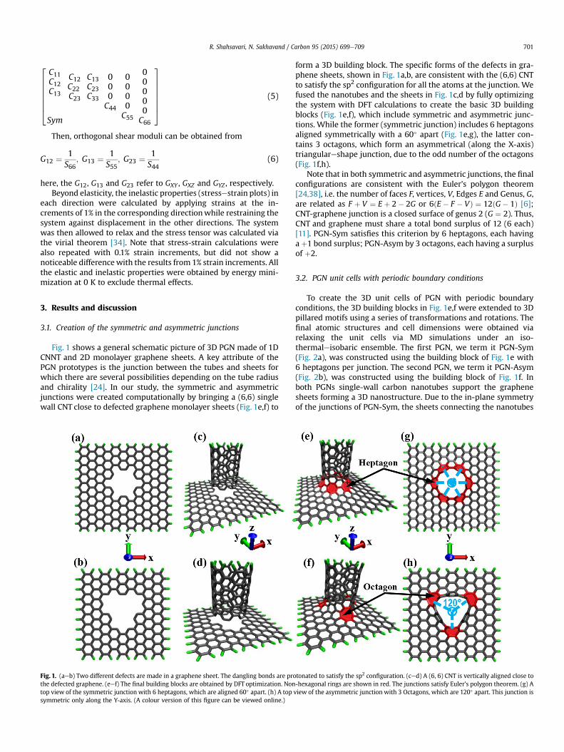
Fig. 1 shows a general schematic picture of 3D PGN made of 1DCNNT and 2D monolayer graphene sheets. A key attribute of thePGN prototypes is the junction between the tubes and sheets forwhich there are several possibilities depending on the tube radiusand chirality [24]. In our study, the symmetric and asymmetricjunctions were created computationally by bringing a (6,6) singlewall CNT close to defected graphene monolayer sheets (Fig. 1e,f) to
Fig. 1. (aeb) Two different defects are made in a graphene sheet. The dangling bonds are prothe defected graphene. (eef) The final building blocks are obtained by DFT optimization. Nontop view of the symmetric junction with 6 heptagons, which are aligned 60� apart. (h) A topsymmetric only along the Y-axis. (A colour version of this figure can be viewed online.)
form a 3D building block. The specific forms of the defects in gra-phene sheets, shown in Fig. 1a,b, are consistent with the (6,6) CNTto satisfy the sp2 configuration for all the atoms at the junction. Wefused the nanotubes and the sheets in Fig. 1c,d by fully optimizingthe system with DFT calculations to create the basic 3D buildingblocks (Fig. 1e,f), which include symmetric and asymmetric junc-tions. While the former (symmetric junction) includes 6 heptagonsaligned symmetrically with a 60� apart (Fig. 1e,g), the latter con-tains 3 octagons, which form an asymmetrical (along the X-axis)triangulareshape junction, due to the odd number of the octagons(Fig. 1f,h).
Note that in both symmetric and asymmetric junctions, the finalconfigurations are consistent with the Euler's polygon theorem[24,38], i.e. the number of faces F, vertices, V, Edges E and Genus, G,are related as F þ V ¼ E þ 2� 2G or 6ðE � F � VÞ ¼ 12ðG� 1Þ [6];CNT-graphene junction is a closed surface of genus 2 (G ¼ 2). Thus,CNT and graphene must share a total bond surplus of 12 (6 each)[11]. PGN-Sym satisfies this criterion by 6 heptagons, each havingaþ1 bond surplus; PGN-Asym by 3 octagons, each having a surplusof þ2.
3.2. PGN unit cells with periodic boundary conditions
To create the 3D unit cells of PGN with periodic boundaryconditions, the 3D building blocks in Fig. 1e,f were extended to 3Dpillared motifs using a series of transformations and rotations. Thefinal atomic structures and cell dimensions were obtained viarelaxing the unit cells via MD simulations under an iso-thermaleisobaric ensemble. The first PGN, we term it PGN-Sym(Fig. 2a), was constructed using the building block of Fig. 1e with6 heptagons per junction. The second PGN, we term it PGN-Asym(Fig. 2b), was constructed using the building block of Fig. 1f. Inboth PGNs single-wall carbon nanotubes support the graphenesheets forming a 3D nanostructure. Due to the in-plane symmetryof the junctions of PGN-Sym, the sheets connecting the nanotubes
tonated to satisfy the sp2 configuration. (ced) A (6, 6) CNT is vertically aligned close to-hexagonal rings are shown in red. The junctions satisfy Euler's polygon theorem. (g) Aview of the asymmetric junction with 3 Octagons, which are 120� apart. This junction is
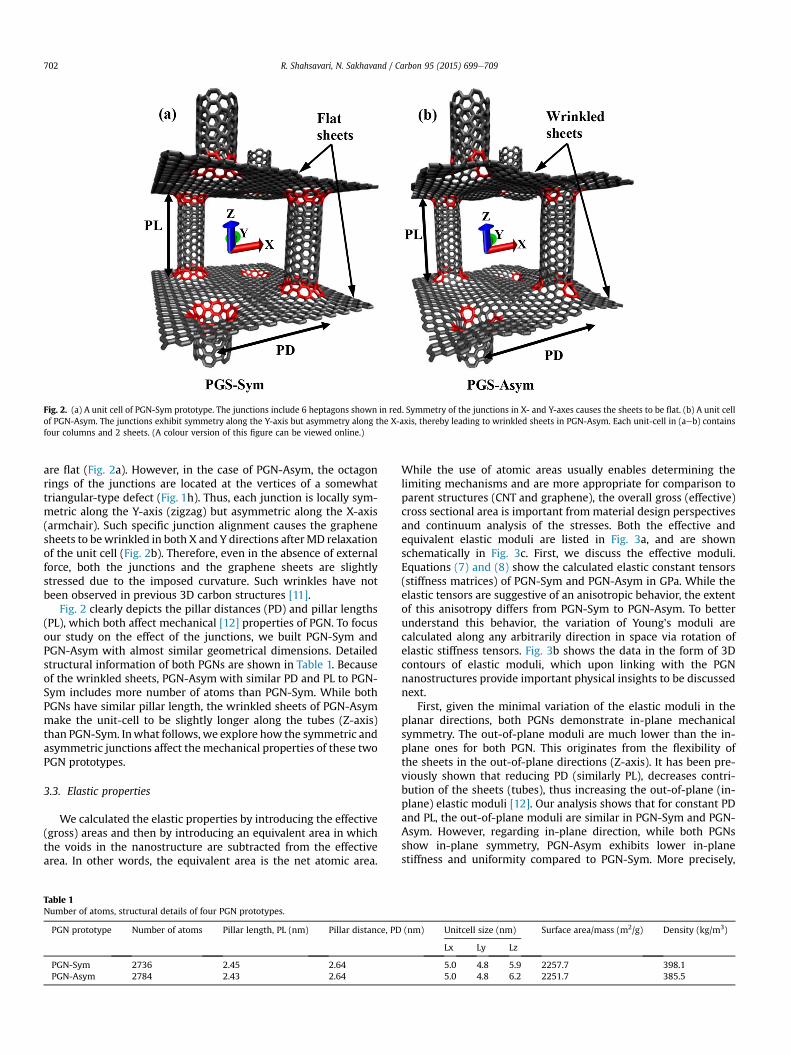
Fig. 2. (a) A unit cell of PGN-Sym prototype. The junctions include 6 heptagons shown in red. Symmetry of the junctions in X- and Y-axes causes the sheets to be flat. (b) A unit cellof PGN-Asym. The junctions exhibit symmetry along the Y-axis but asymmetry along the X-axis, thereby leading to wrinkled sheets in PGN-Asym. Each unit-cell in (aeb) containsfour columns and 2 sheets. (A colour version of this figure can be viewed online.)
R. Shahsavari, N. Sakhavand / Carbon 95 (2015) 699e709702
are flat (Fig. 2a). However, in the case of PGN-Asym, the octagonrings of the junctions are located at the vertices of a somewhattriangular-type defect (Fig. 1h). Thus, each junction is locally sym-metric along the Y-axis (zigzag) but asymmetric along the X-axis(armchair). Such specific junction alignment causes the graphenesheets to bewrinkled in both X and Y directions afterMD relaxationof the unit cell (Fig. 2b). Therefore, even in the absence of externalforce, both the junctions and the graphene sheets are slightlystressed due to the imposed curvature. Such wrinkles have notbeen observed in previous 3D carbon structures [11].
Fig. 2 clearly depicts the pillar distances (PD) and pillar lengths(PL), which both affect mechanical [12] properties of PGN. To focusour study on the effect of the junctions, we built PGN-Sym andPGN-Asym with almost similar geometrical dimensions. Detailedstructural information of both PGNs are shown in Table 1. Becauseof the wrinkled sheets, PGN-Asym with similar PD and PL to PGN-Sym includes more number of atoms than PGN-Sym. While bothPGNs have similar pillar length, the wrinkled sheets of PGN-Asymmake the unit-cell to be slightly longer along the tubes (Z-axis)than PGN-Sym. Inwhat follows, we explore how the symmetric andasymmetric junctions affect the mechanical properties of these twoPGN prototypes.
3.3. Elastic properties
We calculated the elastic properties by introducing the effective(gross) areas and then by introducing an equivalent area in whichthe voids in the nanostructure are subtracted from the effectivearea. In other words, the equivalent area is the net atomic area.
Table 1Number of atoms, structural details of four PGN prototypes.
PGN prototype Number of atoms Pillar length, PL (nm) Pillar distance, PD
PGN-Sym 2736 2.45 2.64PGN-Asym 2784 2.43 2.64
While the use of atomic areas usually enables determining thelimiting mechanisms and are more appropriate for comparison toparent structures (CNT and graphene), the overall gross (effective)cross sectional area is important from material design perspectivesand continuum analysis of the stresses. Both the effective andequivalent elastic moduli are listed in Fig. 3a, and are shownschematically in Fig. 3c. First, we discuss the effective moduli.Equations (7) and (8) show the calculated elastic constant tensors(stiffness matrices) of PGN-Sym and PGN-Asym in GPa. While theelastic tensors are suggestive of an anisotropic behavior, the extentof this anisotropy differs from PGN-Sym to PGN-Asym. To betterunderstand this behavior, the variation of Young's moduli arecalculated along any arbitrarily direction in space via rotation ofelastic stiffness tensors. Fig. 3b shows the data in the form of 3Dcontours of elastic moduli, which upon linking with the PGNnanostructures provide important physical insights to be discussednext.
First, given the minimal variation of the elastic moduli in theplanar directions, both PGNs demonstrate in-plane mechanicalsymmetry. The out-of-plane moduli are much lower than the in-plane ones for both PGN. This originates from the flexibility ofthe sheets in the out-of-plane directions (Z-axis). It has been pre-viously shown that reducing PD (similarly PL), decreases contri-bution of the sheets (tubes), thus increasing the out-of-plane (in-plane) elastic moduli [12]. Our analysis shows that for constant PDand PL, the out-of-plane moduli are similar in PGN-Sym and PGN-Asym. However, regarding in-plane direction, while both PGNsshow in-plane symmetry, PGN-Asym exhibits lower in-planestiffness and uniformity compared to PGN-Sym. More precisely,
(nm) Unitcell size (nm) Surface area/mass (m2/g) Density (kg/m3)
Lx Ly Lz
5.0 4.8 5.9 2257.7 398.15.0 4.8 6.2 2251.7 385.5
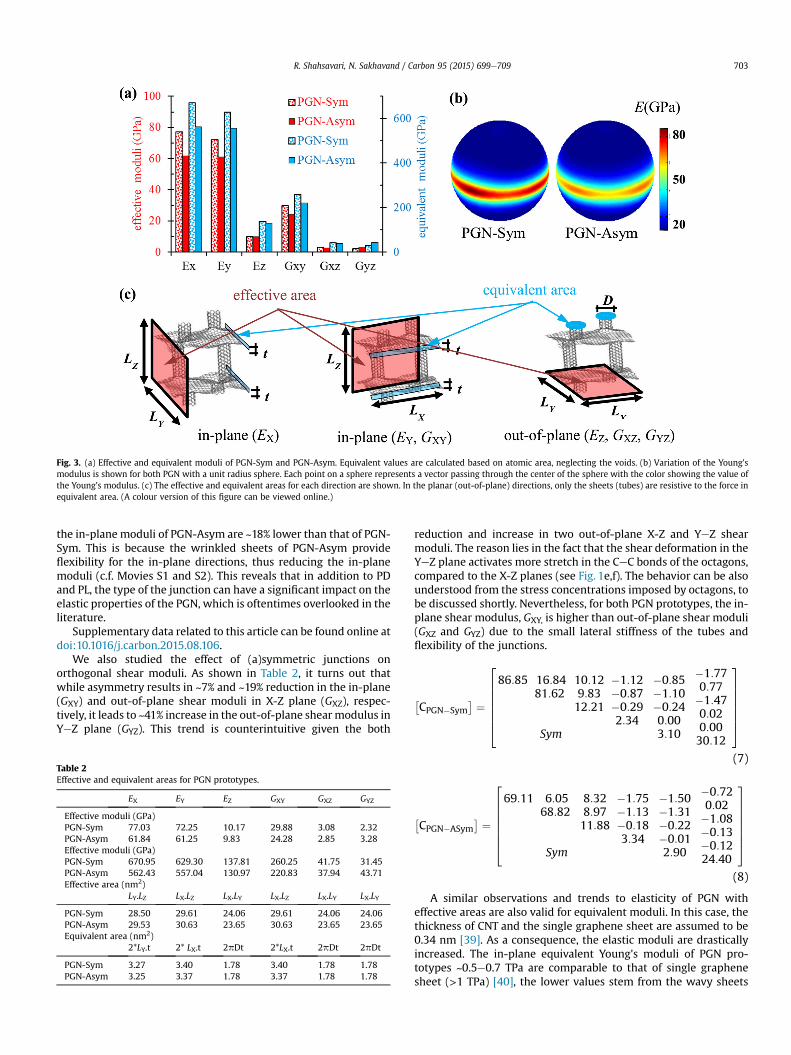
Fig. 3. (a) Effective and equivalent moduli of PGN-Sym and PGN-Asym. Equivalent values are calculated based on atomic area, neglecting the voids. (b) Variation of the Young'smodulus is shown for both PGN with a unit radius sphere. Each point on a sphere represents a vector passing through the center of the sphere with the color showing the value ofthe Young's modulus. (c) The effective and equivalent areas for each direction are shown. In the planar (out-of-plane) directions, only the sheets (tubes) are resistive to the force inequivalent area. (A colour version of this figure can be viewed online.)
R. Shahsavari, N. Sakhavand / Carbon 95 (2015) 699e709 703
the in-plane moduli of PGN-Asym are ~18% lower than that of PGN-Sym. This is because the wrinkled sheets of PGN-Asym provideflexibility for the in-plane directions, thus reducing the in-planemoduli (c.f. Movies S1 and S2). This reveals that in addition to PDand PL, the type of the junction can have a significant impact on theelastic properties of the PGN, which is oftentimes overlooked in theliterature.
Supplementary data related to this article can be found online atdoi:10.1016/j.carbon.2015.08.106.
We also studied the effect of (a)symmetric junctions onorthogonal shear moduli. As shown in Table 2, it turns out thatwhile asymmetry results in ~7% and ~19% reduction in the in-plane(GXY) and out-of-plane shear moduli in X-Z plane (GXZ), respec-tively, it leads to ~41% increase in the out-of-plane shearmodulus inYeZ plane (GYZ). This trend is counterintuitive given the both
Table 2Effective and equivalent areas for PGN prototypes.
EX EY EZ GXY GXZ GYZ
Effective moduli (GPa)PGN-Sym 77.03 72.25 10.17 29.88 3.08 2.32PGN-Asym 61.84 61.25 9.83 24.28 2.85 3.28Effective moduli (GPa)PGN-Sym 670.95 629.30 137.81 260.25 41.75 31.45PGN-Asym 562.43 557.04 130.97 220.83 37.94 43.71Effective area (nm2)
LY.LZ LX.LZ LX.LY LX.LZ LX.LY LX.LY
PGN-Sym 28.50 29.61 24.06 29.61 24.06 24.06PGN-Asym 29.53 30.63 23.65 30.63 23.65 23.65Equivalent area (nm2)
2*LY.t 2* LX.t 2pDt 2*LX.t 2pDt 2pDt
PGN-Sym 3.27 3.40 1.78 3.40 1.78 1.78PGN-Asym 3.25 3.37 1.78 3.37 1.78 1.78
reduction and increase in two out-of-plane X-Z and YeZ shearmoduli. The reason lies in the fact that the shear deformation in theYeZ plane activates more stretch in the CeC bonds of the octagons,compared to the X-Z planes (see Fig. 1e,f). The behavior can be alsounderstood from the stress concentrations imposed by octagons, tobe discussed shortly. Nevertheless, for both PGN prototypes, the in-plane shear modulus, GXY, is higher than out-of-plane shear moduli(GXZ and GYZ) due to the small lateral stiffness of the tubes andflexibility of the junctions.
�CPGN�Sym
� ¼
26666664
86:85 16:8481:62
Sym
10:129:8312:21
�1:12�0:87�0:292:34
�0:85�1:10�0:240:003:10
�1:770:77�1:470:020:0030:12
37777775
(7)
�CPGN�ASym
� ¼
26666664
69:11 6:0568:82
Sym
8:328:9711:88
�1:75�1:13�0:183:34
�1:50�1:31�0:22�0:012:90
�0:720:02�1:08�0:13�0:1224:40
37777775
(8)
A similar observations and trends to elasticity of PGN witheffective areas are also valid for equivalent moduli. In this case, thethickness of CNT and the single graphene sheet are assumed to be0.34 nm [39]. As a consequence, the elastic moduli are drasticallyincreased. The in-plane equivalent Young's moduli of PGN pro-totypes ~0.5e0.7 TPa are comparable to that of single graphenesheet (>1 TPa) [40], the lower values stem from the wavy sheets
R. Shahsavari, N. Sakhavand / Carbon 95 (2015) 699e709704
and relatively flexible junctions, which introduce compliance in thesystem, thus decreasing the elastic moduli. However, the out-of-plane Young's moduli ~0.13 TPa are still ~10 times smaller thanthat of single CNT [41]. This low stiffness comes from the low out-of-plane flexibility of the graphene sheets [42], which contribute tothe out-of-plane moduli of PGN due to discontinuity of the nano-tubes. Simply put, in the out of plane direction, the tube and sheetcan be considered as two springs that are serially connected. Thus,it is the lower stiffness (i.e. graphene) that will be first activatedupon loading in the out of plane direction, hence a lower overalleffective stiffness. Note that since elasticity is mainly aboutperturbation around the equilibrium state, tubes will notcontribute much to the effective stiffness. Instead, their contribu-tion will be manifest beyond elasticity regime, which will be dis-cussed later.
The in-plane and out-of-plane Poisson's ratios of PGN-Sym andPGN-Asym are calculated from stiffness matrices (Eqs. (7) and (8))[43]. While both PGNs exhibit somewhat similar out-of-planePoisson's ratios (Table 3), PGN-Asym's in-plane Poisson's ratio(nxy) is significantly lower (zero or even slightly negative). Note thatour calculated positive Poisson's ratio for PGN-Sym is in contrast tothe negative Poisson's ratio previously calculated for a symmetricPGN using finite elements simulations [12]. We believe that thisdiscrepancy is due to the inaccuracy of finite elements method andthe associated empirical parameterizations of the elements inpredicting material properties at the molecular level where MD isnaturally a more reliable choice. Furthermore, we ascribe the zero(and perhaps negative) in-plane Poisson's ratio of PGN-Asym to itswrinkled sheets, similar to what has been observed in PillaredBoron Nitride nanostructure with asymmetric junctions andwrinkled sheets [43]. More precisely, upon loading along a certaindirection, the wrinkled sheets flatten out in all the directions, thusbringing about a tensile strain in competitionwith the compressivestrain transverse to the applied tensile loading (Movie S1). Conse-quently, PGN-Asym might be better choice than PGN-Sym forfabrication of nanomaterials that require zero in-plane Poisson'sratio or auxetic nanomaterials which expand (shrink) laterally uponpulling (pushing) [44], with potential applications in sieving, strainsensing, gas separation and shock energy absorption [44,45].
3.4. Inelastic deformation mechanism, strength and toughness
Mechanical responses beyond elasticity can provide essentialinformation on deformation mechanisms, which control strengthand toughness preceding the materials failure. We studied thestress-strain behavior of PGNs until failure using MD simulations.Equivalent areas are used to calculate the stresses to better un-derstand the underlying physics and compare the results with pureparent structures. Fig. 4 show the stress-strain results for the twoPGN prototypes along with average CeC bond strains and stresscontour plots. To our knowledge, this work is the first report on fullstress-strain behaviors of any PGN structure until failure. Forcomparison, Fig. 4aec also shows the stressestrain plots of pureCNT and graphene, obtained from identical method and force fieldpotential. First, we will discuss interesting (common) deformationmechanisms in both PGN-Sym and PGN-Asym and then highlighttheir differences.
Table 3In-plane and out-of-plane Poisson's ratios of PGNs.
nxy vxz vyz
PGN-Sym 0.106 0.095 0.101PGN-Asym �0.020 0.111 0.122
3.4.1. Out-of-plane deformation: a two-regime synergisticdeformation
In view of the data in Fig. 4a, the ultimate strain of both PGNs(εUz42%Þ along the out-of-plane direction is z14% larger thanthat of pure CNT (εUz28%Þ while maintaining similar ultimatestresses, sUz110 GPa. This significant stretching capacity stemsfrom cooperation of two distinct deformation regimes (see MovieS3). The first regime consists of mainly the out-of-plane deforma-tion of the sheets, i.e. the geometrical re-arrangements of thegraphene rings in the vicinity of the junctions. In this regime,although tubes are slightly strained, the geometric (rigid body type)displacement of the in-plane carbon rings (sheets) contributesmost to the out-of-plane deformation while bearing small actualCeC bond strains. However, CeC bonds in the octagonal rings(junctions) are highly strained to pass the imposed vertical strain tothe horizontal sheets. This can be understood from the averagedbond strains in Fig. 4bec and stress concentrations (red dots) inFig. 4dee. In the case of PGN-Sym (PGN-Asym), the heptagonal(octagonal) ring capacities become exhausted at εz31% (εz26%Þand their bond strains remain almost unchanged. At this point,which is the onset of the second regime (backbone stretching), themajority of the strains start to be transferred to the CNT. In thissecond regime, the actual CeC bonds in the CNT tubes are signifi-cantly stretched until final failure at εUz42%. As indicated inFig. 4bec and Movie S3 in SI, the non-hexagonal rings of thejunctions always bear the maximum average strains, thus thejunctions will act as the weakest link in the overall fracture.Fig. 4dee shows highly stressed atoms, which are primarily at thejunctions, causing the tubes to rip out of the graphene layers.
Supplementary data related to this article can be found online atdoi:10.1016/j.carbon.2015.08.106.
Together, the first and second deformation regimes in PGNsprovide an out-of-plane toughness (area under the stress-straincurve) of z23.1 GPa for PGN, which despite the lower stiffness, iscomparable to that of pure CNT (23.0 GPa) (Fig. 4a). Note that here“toughness” is defined as the amount of energy per volume a ma-terial absorbs before failure (representing the work-of-fracture)[46e48]. This definition is different from the classical “fracturetoughness” with the unit of Pa
ffiffiffiffiffim
p. The work-of-fracture is the area
under the stressestrain curve and is profoundly affected by gradual,graceful fracture, whereas the “fracture toughness” does notincorporate this entire process [48].We emphasize that it is the firstdeformation regime that provides the extra ductility and tough-ness. Interestingly, such a high toughness is not sacrificed by a lowstrength, which is typically expected in engineered materials[49e51]. This improved balance of strength and toughness alongthe out-of-plane direction of both PGNs is enabled by the cooper-ative behavior of tubes, junctions and out-of-plane flexibility of thesheets, and is a significant result of this paper. A somewhat similarcooperative effect in improving mechanical properties are reportedfor nanocarbons of different dimensionalities [52].
3.4.2. In-plane deformationsWhile PGN prototypes and graphene exhibit a somewhat similar
in-plane stressestress behavior (Fig. 4f,k), it appears that thelocalized nature of strains on the junctions of PGNs alters the in-plane failure mechanism compared to that of graphene. Moreprecisely, by strain localization around the octagonal or heptagonalrings, the cracks in PGNs initiate from these points and propagate atan inclined angle with respect to the direction of applied load (seedashed lines in Fig. 4i,j and Fig. 4n,o).
Within the in-plane directions of PGN, the ultimate stress,sUz120 GPa, in the zigzag (Y) direction is larger than sUz100 GPain the armchair (X) direction (c.f. Fig. 4f,k). This disparity, which inpart stems from the bond (zigzag versus armchair) orientations, is
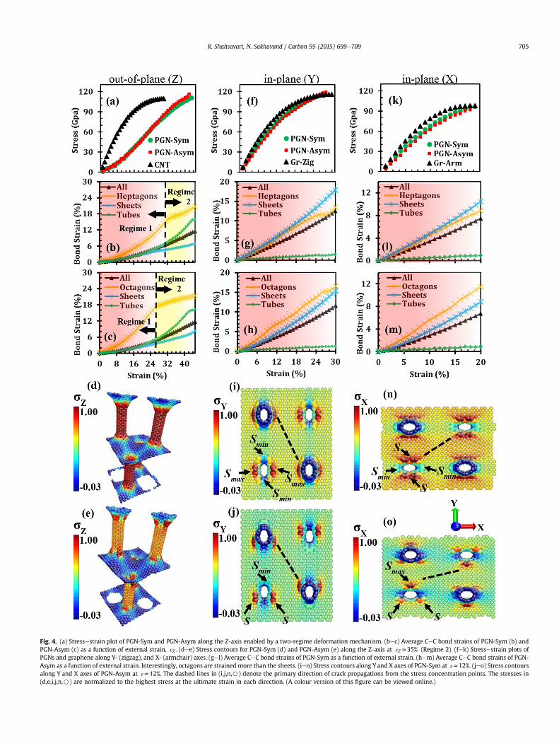
Fig. 4. (a) Stressestrain plot of PGN-Sym and PGN-Asym along the Z-axis enabled by a two-regime deformation mechanism. (bec) Average CeC bond strains of PGN-Sym (b) andPGN-Asym (c) as a function of external strain, εZ . (dee) Stress contours for PGN-Sym (d) and PGN-Asym (e) along the Z-axis at εZz35% (Regime 2). (fek) Stressestrain plots ofPGNs and graphene along Y- (zigzag), and X- (armchair) axes. (gel) Average CeC bond strains of PGN-Sym as a function of external strain. (hem) Average CeC bond strains of PGN-Asym as a function of external strain. Interestingly, octagons are strained more than the sheets. (ien) Stress contours along Y and X axes of PGN-Sym at εz12%. (jeo) Stress contoursalong Y and X axes of PGN-Asym at εz12%. The dashed lines in (i,j,n,B) denote the primary direction of crack propagations from the stress concentration points. The stresses in(d,e,i,j,n,B) are normalized to the highest stress at the ultimate strain in each direction. (A colour version of this figure can be viewed online.)
R. Shahsavari, N. Sakhavand / Carbon 95 (2015) 699e709 705
R. Shahsavari, N. Sakhavand / Carbon 95 (2015) 699e709706
also observed in our MD simulation of graphene, and is verified byDFT calculations on graphene [53]. However, there is anothermechanism that contributes to this difference in PGN prototypes:the heptagonal and octagonal rings, which are the hot spots undermechanical loading, undergo different stresses in armchair versuszigzag directions. For example, when the PGN-Asym is under axialstrain in the zigzag direction, one third of all the octagonal rings(symbolized by Smin in Fig. 4j) are furthest away from the stressconcentration points and thus bear minimum stresses (Fig. 5a).However, when the PGN-Asym is strained along the armchair di-rection, these same octagonal rings (symbolized by Smax in Fig. 4o)are exactly coincided with the stress concentration points and thushave to sustain maximum stresses (the rest of the octagons bearsomewhat similar stresses regardless of the direction of appliedstrain). Therefore, both bond orientation and stress concentrationsin PGN-Asym lead to smaller strength capacity along the armchairdirection than zigzag direction. A similar observation is valid forPGN-Sym.
3.4.3. Effect of junction type on deformation mechanismsOur results in Fig. 4 denote that while the symmetric vs asym-
metric junction does not significantly alter the ultimate strain,strength, and toughness of PGN prototypes, their deformation andfailure mechanisms are different in the two structures. In the out-of-plane direction, the first deformation regime of PGN-Asymends at εz26% , which is ~16% lower strain than that of PGN-Sym. This indicates that the three octagons in PGN-Asym have
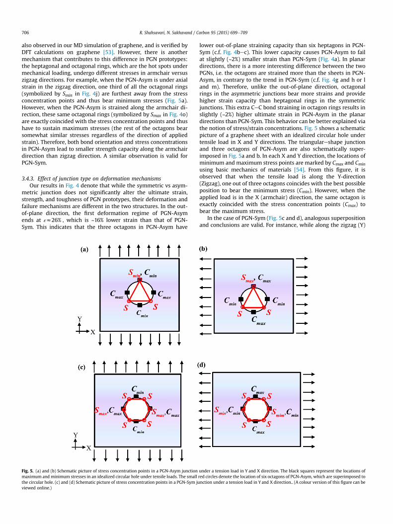
Fig. 5. (a) and (b) Schematic picture of stress concentration points in a PGN-Asym junctionmaximum and minimum stresses in an idealized circular hole under tensile loads. The smallthe circular hole. (c) and (d) Schematic picture of stress concentration points in a PGN-Sym juviewed online.)
lower out-of-plane straining capacity than six heptagons in PGN-Sym (c.f. Fig. 4bec). This lower capacity causes PGN-Asym to failat slightly (~2%) smaller strain than PGN-Sym (Fig. 4a). In planardirections, there is a more interesting difference between the twoPGNs, i.e. the octagons are strained more than the sheets in PGN-Asym, in contrary to the trend in PGN-Sym (c.f. Fig. 4g and h or land m). Therefore, unlike the out-of-plane direction, octagonalrings in the asymmetric junctions bear more strains and providehigher strain capacity than heptagonal rings in the symmetricjunctions. This extra CeC bond straining in octagon rings results inslightly (~2%) higher ultimate strain in PGN-Asym in the planardirections than PGN-Sym. This behavior can be better explained viathe notion of stress/strain concentrations. Fig. 5 shows a schematicpicture of a graphene sheet with an idealized circular hole undertensile load in X and Y directions. The triangulareshape junctionand three octagons of PGN-Asym are also schematically super-imposed in Fig. 5a and b. In each X and Y direction, the locations ofminimum and maximum stress points are marked by Cmax and Cmin
using basic mechanics of materials [54]. From this figure, it isobserved that when the tensile load is along the Y-direction(Zigzag), one out of three octagons coincides with the best possibleposition to bear the minimum stress (Cmin). However, when theapplied load is in the X (armchair) direction, the same octagon isexactly coincided with the stress concentration points (Cmax) tobear the maximum stress.
In the case of PGN-Sym (Fig. 5c and d), analogous superpositionand conclusions are valid. For instance, while along the zigzag (Y)
under a tension load in Y and X direction. The black squares represent the locations ofred circles denote the location of six octagons of PGN-Asym, which are superimposed tonction under a tension load in Y and X direction.. (A colour version of this figure can be
R. Shahsavari, N. Sakhavand / Carbon 95 (2015) 699e709 707
direction, two out of the six heptagons are maximally stressed, fourout of the six heptagons are nearly (not exactly) maximally stressedalong the armchair direction. Note that in the case of PGN-Sym,since the number of heptagons (6) is larger than octagons (3) inPGN-Asym, the stress/strain concentrations are more equallydivided, resulting in lower strain values in heptagons. This explainswhy octagons in PGN-Asym bear more strains in the planar di-rections than heptagons in PGN-Sym, surpassing the average CeCbond strain of the sheets in PGN-Asym.
4. Discussions
Given the wealth of existing literature on hybrid carbon basedmaterials and the importance of these materials on pioneeringtechnological advances, in this section we will discuss the keynovelties and insights of this work along with necessary futurestudies from a materials design perspective. The discussions aresummarized in four key parts as follows.
� While Section 1 (Introduction) already has referred to and dis-cussed the key reports on mechanical properties of 3D carbonmaterials, to our knowledge there has been no rigorous andcomplete study such as the present work on the effect of sym-metric versus asymmetric junction topologies on the elastic andinelastic properties of PGN including full elastic tensors, bondstrains, strength, ductility and toughness in all three-dimensional directions. Each work in the literature has typi-cally addressed a limited feature or functionality of PGN along acertain direction with restricted implications.
� Identification of a two-regime deformation mechanism is a keynovel aspect of this work that has been overlooked in previousstudies. Understanding and tuning this cooperative deformationmechanism provides new insights on how to fuse various col-umns and sheets via covalent junctions to provide largerductility and toughness without scarifying the strength. This isan interesting attribute that is highly desired in synthetic ma-terials because toughness and strength are antagonistic me-chanical properties in synthetic materials. Our work quantifiesand clearly demonstrates how the synergies of CNTs, junctiontypes and graphene sheets provide new degrees of freedom toaddress one of the key fundamental challenges of syntheticmaterials: that is the conflict between strength and toughness.This by itself is a key finding that provides new insights on howto strategize and design de novo 3D carbon-based nanomaterialstoward this long engineering pursuit in materials.
� Our work for the first time demonstrates that depending on thetopology of the defect in the graphene sheets, the junction ofPGN may end up being symmetric or asymmetric, which causedifferent elastic properties and fracture mechanisms. Forinstance, as shown in Fig. 2a, asymmetric junctions lead towrinkled (wavy) graphene sheets, providing ~15e20% highercompliance (lower stiffness) along the in-plane directions ascompared to their counterparts in straight graphene sheets withsymmetric junctions (compare Ex, and Ey for PGN-Sym andPGN-Asym in Table 2). Similarly, the topology of symmetricversus asymmetric junctions influences the fracture processesthat can be important from a material design perspective. Forinstance, as shown in Fig. 4bec, the asymmetric junctions lowerthe critical strain between deformation regime 1 and 2 by ~16%,causing the tubes to be stressed more quickly than in the case ofsymmetric junctions (compare the start of regime 2 inFig. 4bec). From a design perspective and considering that realCNTs have defects, the asymmetric junctions may not allow toutilize the full ductility and toughness capacity of PGN since thebackbone of the tubes will be rapidly exposed to the external
strain (regime 2). Therefore, when it comes to designing pillaredgraphene, it is important to ensure that the defected graphenesheet and the CNT type (armchair or zigzag) end up in a sym-metric junction. However, if fracture and ductility is not an issueand more compliance and zero (negative) Poisson's ratios aredesired, then asymmetric junctions are the preferred choice.
� We deliberately performedMD to the idealized limit of behaviorat T¼ 0 K via quasi-static loading to exclude thermally activatedprocesses and strain rate effects. This might introduce someinconsistencies for comparison with experiments, materialsdesign and functionality, which are typically subject to roomtemperature and finite strains. However, in view of the existingliterature on the effects of temperature and strain rate on carbonbased nanomaterials [55e58], we expect that mechanicalproperties, in particular fracture strength and fracture strain,will be reduced by increasing temperature and/or decreasingstrain rate. In the case of temperature, this behavior is primarilybecause of the increased kinetic energy, more bond displace-ments, and defect formation associated with the higher tem-peratures. In the case of strain, the bond displacements/reconfigurations do have ample times to re-arrange themselvesto lower energy states in slow strain rates, thus preventing thesystem to be on high-energy or metal stable local states, whichcause unrealistically high mechanical properties. Furthermore,in the context of PGN, one may expect that there will becompetition between the defects and grain boundaries in CNTand graphene versus those of the (a)symmetric junctions andpotential impurities (Fe, Ni, etc.) of the junctions in controllingthe mechanical properties. A detailed and unified understand-ing of the effect of temperature and strain rates on PGN requiresa separate study, which is beyond the focus of the presentmanuscript.
Broadly, the above insights, novelties and discussion can beapplied to other low-dimensional materials, such as Boron Nitridenanotubes/sheets, Molybdenum/Tungsten disulphide (MoS2/WS2)or the combination thereof, towards creating multifunctional 3Dnanomaterials with mutable mechano-electro-thermo-opticalproperties [59].
5. Conclusions
We probed the effect of symmetric versus asymmetric junctionsin controlling deformation mechanisms, and elastic and inelasticproperties of pillared graphene via first-principles and moleculardynamics simulations. Unlike the stacked of graphene sheets,which exhibit weak out-of-plane properties, both junction typesresult in substantial improvements in the out-of-plane mechanicalproperties of PGN via a two-regime deformation mechanism. Inthis context, a synergistic geometrical feature is manifest viacooperation of junctions, tubes and sheets in the 3D architecture.This unique feature can overcome the intrinsic limitations of the 1Dand 2D constituents of PGN and impart superior propertiesincluding 3D balance of strength and toughness as well as anoutstanding ~42% out-of-plane ductility preceding the failure. Wedemonstrated that asymmetric junctions results in wrinkledsheets, which cause extra in-plane flexibility and shear complianceas well as a nearly zero/negative in-plane Poisson's ratio in PGN,thereby providing a new degree of freedom to control elasticproperties. Although the symmetric and asymmetric junctions donot significantly alter the ultimate strain, strength, and toughnessof PGN prototypes, the failure mechanisms are different in the twostructures. The octagonal rings in PGN with asymmetric junctionsbear more strains than the sheets, and act as hotspots for initiationof the fracture; a behavior that may not be present in PGN with
R. Shahsavari, N. Sakhavand / Carbon 95 (2015) 699e709708
symmetric junctions, owing to its symmetrically distributed strainconcentrations in the heptagonal rings. To our knowledge, thiswork is the first report on the full stress-strain behavior of any PGNstructure.
Broadly, our findings lay the foundation for discovering andstudying numerous junction-induced hybrid 3D carbon architec-tures by fusing low dimensional building blocks including 0Dfullerene, 1D nanotubes and 2D nanosheets. A rich set of hybridcarbon nanostructures have been developed and studied over thepast years. However, similar advances for studying the effects ofjunctions have thus far remained elusive. To the best of ourknowledge, this paper for the first time provides an atomistic “lens”to explore the diverse junction-mediated mechanical properties ofPGN. This study potentially opens up a new phase space to tunehybrid carbon-based nanoelectronics and also can impactknowledge-based use of such nanomaterials as 3D fillers tomodulate hybrid functional composites and layered materials[60e63].
Author contributions
R.S. designed the research; N.S and R.S performed the compu-tational and experimental research; N.S. and R.S analyzed the data;and R.S. wrote the paper.
Competing financial interest
The authors declare no competing financial interest.
Acknowledgments
This work was supported in part by Rice University and in partby NSF grant number CMMI-1235522. The supercomputer ma-chines utilized in this work were supported in part by NIH awardNCRR S10RR02950 and an IBM Shared University Research (SUR)Award in partnership with CISCO, Qlogic and Adaptive Computing,and in part by the Data Analysis and Visualization Cyber infra-structure funded by NSF under grant OCI-0959097.
References
[1] M.F.L. De Volder, S.H. Tawfick, R.H. Baughman, A.J. Hart, Carbon nanotubes:present and future commercial applications, Science 339 (6119) (2013)535e539.
[2] C. Lee, X. Wei, J.W. Kysar, J. Hone, Measurement of the elastic properties andintrinsic strength of monolayer graphene, Science 321 (5887) (2008)385e388.
[3] X. Huang, Z. Yin, S. Wu, X. Qi, Q. He, Q. Zhang, et al., Graphene-based mate-rials: synthesis, characterization, properties, and applications, Small 7 (14)(2011) 1876e1902.
[4] E.T. Thostenson, Z. Ren, T.W. Chou, Advances in the science and technology ofcarbon nanotubes and their composites: a review, Compos. Sci. Technol. 61(13) (2001) 1899e1912.
[5] D.J. Hornbaker, S.-J. Kahng, S. Misra, B.W. Smith, A.T. Johnson, E.J. Mele, et al.,Mapping the one-dimensional electronic states of nanotube peapod struc-tures, Science 295 (5556) (2002) 828e831.
[6] J. Lee, H. Kim, S.J. Kahng, G. Kim, Y.W. Son, J. Ihm, et al., Bandgap modulation ofcarbon nanotubes by encapsulated metallo fullerenes, Nature 415 (6875)(2002) 1005e1008.
[7] S. Okada, S. Saito, A. Oshiyama, Energetics and electronic structures ofencapsulated C_{60} in a carbon nanotube, Phys. Rev. Lett. 86 (17) (2001)3835e3838.
[8] A.G. Nasibulin, P.V. Pikhitsa, H. Jiang, D.P. Brown, A.V. Krasheninnikov,A.S. Anisimov, et al., A novel hybrid carbon material, Nat. Nano 2 (3) (2007)156e161.
[9] X. Wu, X.C. Zeng, Periodic graphene nanobuds, Nano Lett. 9 (1) (2009)250e256.
[10] F. Ding, Y. Lin, P.O. Krasnov, B.I. Yakobson, Nanotube-derived carbon foam forhydrogen sorption, J. Chem. Phys. 127 (16) (2007) 164703e164706.
[11] G.K. Dimitrakakis, E. Tylianakis, G.E. Froudakis, Pillared graphene: a new 3-Dnetwork nanostructure for enhanced hydrogen storage, Nano Lett. 8 (10)(2008) 3166e3170.
[12] S. Sihn, V. Varshney, A.K. Roy, B.L. Farmer, Prediction of 3D elastic moduli andPoisson's ratios of pillared graphene nanostructures, Carbon 50 (2) (2012)603e611.
[13] V. Varshney, S.S. Patnaik, A.K. Roy, G. Froudakis, B.L. Farmer, Modeling ofthermal transport in pillared-graphene architectures, ACS Nano 4 (2) (2010)1153e1161.
[14] C.-H. Wang, T.-H. Fang, W.-L. Sun, Mechanical properties of pillared-graphenenanostructures using molecular dynamics simulations, J. Phys. D Appl. Phys.47 (40) (2014) 405302.
[15] J. Niu, M. Li, Z. Xia, Growth mechanisms and mechanical properties of 3Dcarbon nanotube-graphene junctions: molecular dynamic simulations, RSCAdv. 4 (64) (2014) 33848e33854.
[16] Sasaki H, Hagi T, Shintani K. Mechanical properties of pillared-graphenenanostructures under shear loads. Materials Research Society Proceeding.Cambridge; Cambridge University Press. p. mrsf12-1505-w10-27.
[17] R.P. Wesolowski, A.P. Terzyk, Pillared graphene as a gas separation mem-brane, Phys. Chem. Chem. Phys. 13 (38) (2011) 17027e17029.
[18] F.D. Novaes, R. Rurali, P. Ordej�on, Electronic transport between graphenelayers covalently connected by carbon nanotubes, ACS Nano 4 (12) (2010)7596e7602.
[19] R.K. Paul, M. Ghazinejad, M. Penchev, J. Lin, M. Ozkan, C.S. Ozkan, Synthesis ofa pillared graphene nanostructure: a counterpart of three-dimensional carbonarchitectures, Small 6 (20) (2010) 2309e2313.
[20] J. Lin, J. Zhong, D. Bao, J. Reiber-Kyle, W. Wang, Supercapacitors based onpillared graphene nanostructures, J. Nanosci. Nanotechnol. 12 (3) (2012)1770e1775.
[21] J. Park, V. Prakash, Phonon scattering and thermal conductivity of pillaredgraphene structures with carbon nanotube-graphene intramolecular junc-tions, J. Appl. Phys. 116 (1) (2014) 014303.
[22] W. Chih-Hao, F. Te-Hua, S. Wei-Li, Mechanical properties of pillared-graphenenanostructures using molecular dynamics simulations, J. Phys. D Appl. Phys.47 (40) (2014) 405302.
[23] G.C. Loh, E.H.T. Teo, B.K. Tay, Tuning the Kapitza resistance in pillared-graphene nanostructures, J. Appl. Phys. 111 (1) (2012) 013515e013516.
[24] D. Baowan, B.J. Cox, J.M. Hill, Joining a Carbon Nanotube and a GrapheneSheet, 2008, pp. 5e8.
[25] R.G. Parr, W. Yang, Density-functional Theory of Atoms and Molecules, OxfordUniversity Press, USA, 1994.
[26] S. Plimpton, Fast parallel algorithms for short-range molecular dynamics,J. Comput. Phys. 117 (1) (1995) 1e19.
[27] S.J. Stuart, A.B. Tutein, J.A. Harrison, A reactive potential for hydrocarbons withintermolecular interactions, J. Chem. Phys. 112 (14) (2000) 6472e6486.
[28] R. Grantab, V.B. Shenoy, R.S. Ruoff, Anomalous strength characteristics of tiltgrain boundaries in graphene, Science 330 (6006) (2010) 946e948.
[29] Y. Wei, J. Wu, H. Yin, X. Shi, R. Yang, M. Dresselhaus, The nature of strengthenhancement and weakening by pentagoneheptagon defects in graphene,Nat. Mater 11 (9) (2012) 759e763.
[30] S.A. Nose, Unified formulation of the constant temperature molecular dy-namics methods, J. Chem. Phys. 81 (1) (1984) 511e519.
[31] W.G. Hoover, Canonical dynamics: equilibrium phase-space distributions,Phys. Rev. A 31 (3) (1985) 1695e1697.
[32] W. Humphrey, A. Dalke, K. Schulten, VMD: visual molecular dynamics, J. Mol.Graph. 14 (1) (1996) 33e38.
[33] J. Li, AtomEye: an efficient atomistic configuration viewer, Modell. Simul.Mater Sci. Eng. 11 (2) (2003) 173e177.
[34] S. Okada, S. Saito, A. Oshiyama, Energetics and electronic structures ofencapsulated C60 in a carbon nanotube, Phys. Rev. Lett. 86 (17) (2001)3835e3838.
[35] R. Shahsavari, M.J. Buehler, R.J.M. Pellenq, F.-J. Ulm, First-principles study ofelastic constants and interlayer interactions of complex hydrated oxides: casestudy of tobermorite and jennite, J. Am. Ceram. Soc. 92 (10) (2009)2323e2330.
[36] J.F. Nye, Physical Properties of Crystals Oxford, Oxford University Press, En-gland, 1957.
[37] R. Shahsavari, R.J.M. Pellenq, F.-J. Ulm, Empirical force fields for complexhydrated calcio-silicate layered materials, PCCP 13 (3) (2011) 1002e1011.
[38] P.R. Cromwell, Polyhedra, Cambridge University Press, 1997.[39] Y. Huang, J. Wu, K.C. Hwang, Thickness of graphene and single-wall carbon
nanotubes, Phys. Rev. B 74 (24) (2006) 245413.[40] F. Scarpa, S. Adhikari, A.P. Srikantha, Effective elastic mechanical properties of
single layer graphene sheets, Nanotechnology 20 (6) (2009).[41] A. Krishnan, E. Dujardin, T.W. Ebbesen, P.N. Yianilos, M.M.J. Treacy, Young's
modulus of single-walled nanotubes, Phys. Rev. B 58 (20) (1998)14013e14019.
[42] Q. Wang, Simulations of the bending rigidity of graphene, Phys. Lett. A 374 (9)(2010) 1180e1183.
[43] N. Sakhavand, R. Shahsavari, Synergistic behavior of tubes, junctions, andsheets imparts mechano-mutable functionality in 3D porous boron nitridenanostructures, J. Phys. Chem. C 118 (39) (2014) 22730e22738.
[44] W. Yang, Z.-M. Li, W. Shi, B.-H. Xie, M.-B. Yang, Review on auxetic materials,J. Mater Sci. 39 (10) (2004) 3269e3279.
[45] J.N. Grima, R. Jackson, A. Alderson, K.E. Evans, Do zeolites have negativepoisson's ratios? Adv. Mater 12 (24) (2000) 1912e1918.
[46] M.A. Meyers, J. McKittrick, P.-Y. Chen, Structural biological materials: criticalmechanics-materials connections, Science 339 (6121) (2013) 773e779.
R. Shahsavari, N. Sakhavand / Carbon 95 (2015) 699e709 709
[47] U.G.K. Wegst, M.F. Ashby, The mechanical efficiency of natural materials,Philos. Mag. 84 (21) (2004) 2167e2186.
[48] M.A. Meyers, P.-Y. Chen, A.Y.-M. Lin, Y. Seki, Biological materials: structureand mechanical properties, Prog. Mater Sci. 53 (1) (2008) 1e206.
[49] R.O. Ritchie, The conflicts between strength and toughness, Nat. Mater 10 (11)(2011) 817e822.
[50] N. Sakhavand, P. Muthuramalingam, R. Shahsavari, Toughness governs therupture of the interfacial h-bond assemblies at a critical length scale in hybridmaterials, Langmuir 29 (25) (2013) 8154e8163.
[51] N. Sakhavand, R. Shahsavari, Universal composition-structure-property mapsfor natural and biomimetic platelet-matrix composites and stacked hetero-structures, Nat. Commun. 6 (2015) 6523.
[52] K.E. Prasad, B. Das, U. Maitra, U. Ramamurty, C.N.R. Rao, Extraordinary synergyin the mechanical properties of polymer matrix composites reinforced with 2nanocarbons, Proc. Natl. Acad. Sci. 106 (32) (2009) 13186e13189.
[53] Q. Peng, Z. Chen, S. De, A density functional theory study of the mechanicalproperties of graphane with van der Waals corrections, Mech. Adv. Mater.Struct. 22 (9) (2014) 717e721.
[54] E.J. Hearn, Mechanics of Materials 2: the Mechanics of Elastic and PlasticDeformation of Solids and Structural Components, 2 ed, Butterworth-Heine-mann Ltd, 1995.
[55] M. Daly, M. Reeve, C. Veer Singh, Effects of topological point reconstructionson the fracture strength and deformation mechanisms of graphene, Comput.
Mater. Sci. 97 (2015) 172e180.[56] M. Daly, C. Veer Singh, A kinematic study of energy barriers for crack for-
mation in graphene tilt boundaries, J. Appl. Phys. 115 (22) (2014) 223513.[57] C. Wei, K. Cho, D. Srivastava, Tensile strength of carbon nanotubes under
realistic temperature and strain rate, Phys. Rev. B 67 (11) (2003) 115407.[58] H. Zhao, N.R. Aluru, Temperature and strain-rate dependent fracture strength
of graphene, J. Appl. Phys. 108 (6) (2010) 064321.[59] N. Sakhavand, R. Shahsavari, Dimensional crossover of thermal transport in
hybrid boron nitride nanostructures, ACS Appl. Mater. Interfaces 7 (33) (2015)18312e18319.
[60] M.A. Rafiee, T.N. Narayanan, D.P. Hashim, N. Sakhavand, R. Shahsavari,R. Vajtai, et al., Hexagonal boron nitride and graphite oxide reinforcedmultifunctional porous cement composites, Adv. Funct. Mater 23 (45) (2013)5624e5630.
[61] S. Jalilvand, R. Shahsavari, Molecular mechanistic origin of nanoscale contact,friction, and scratch in complex particulate systems, ACS Appl. Mater In-terfaces 7 (5) (2015) 3362e3372.
[62] M. Prakash, N. Sakhavand, R. Shahsavari, H2, N2, and CH4 gas adsorption inzeolitic imidazolate framework-95 and -100: ab initio based grand canonicalMonte Carlo simulations, J. Phys. Chem. C 117 (46) (2013) 24407e24416.
[63] R. Shahsavari, L. Chen, Screw dislocations in complex, low symmetry oxides:core structures, energetics, and impact on crystal growth, ACS Appl. MaterInterfaces 7 (4) (2015) 2223e2234.