JUMO dTRON 304/308/316 Compact Controller with program … · 2017-01-11 · JUMO dTRON 304/308/316...
10
Page 1/10 JUMO GmbH & Co. KG Delivery address:Mackenrodtstraße 14, 36039 Fulda, Germany Postal address: 36035 Fulda, Germany Phone: +49 661 6003-0 Fax: +49 661 6003-607 e-mail: [email protected] Internet: www.jumo.net JUMO Instrument Co. Ltd. JUMO House Temple Bank, Riverway Harlow, Essex CM 20 2TT, UK Phone: +44 1279 635533 Fax: +44 1279 635262 e-mail: [email protected] Internet: www.jumo.co.uk JUMO Process Control, Inc. 8 Technology Boulevard Canastota, NY 13031, USA Phone: 315-697-JUMO 1-800-554-JUMO Fax: 315-697-5867 e-mail: [email protected] Internet: www.jumo.us Data Sheet 70.304101 01.06/00442069 Block structure Option boards: – Analog input – 2 logic inputs – 1 relay 230V/8A (changeover) – 2 relays 230V/3A (make contact) with common pole – 1 solid-state relay – Analog output (voltage/current) – RS422/485 interface – Profibus-DP interface JUMO dTRON 304/308/316 Compact Controller with program function Brief description The J dTRON 300 series of controllers includes four freely programmable instruments in different DIN formats for controlling temperature, pressure and other process variables. The high-contrast, multicolor LC display for process value, setpoint and operator prompting contains two four-digit 7-segment displays, two single-character 16-segment displays, display of the active setpoints, six switch position indicators, and displays for the dimensional unit, ramp function and manual operation. Simple operation through 4 keys. The instruments can be used as 2-state, 3-state, modulating or continuous controllers. The controller software includes a program or ramp function, parameter set changeover, two autotuning (self-optimization) procedures, a math and logic module, as well as 4 limit comparators. Linearizations for the usual transducers are stored, and a customer-specific linearization table can be programmed. A setup program is available for user-friendly configuration from a PC. A serial interface for RS422/485 or Profibus-DP can be used to integrate the instruments into a data network. The electrical connection is made at the back, via screw terminals. The possible input and output configurations are shown in the following block diagram. The option boards are universally applicable for all instruments in the series. JdTRON 304 Type 703044/ ... JdTRON 308Q Type 703043/ ... JdTRON 308H Type 703042/ ... JdTRON 316 Type 703041/ ... Key features ! Max. two programmable analog inputs ! Four programmable setpoints, two parameter sets ! Program function with 8 segments, or ramp function ! Math and logic module ! 4 limit comparators ! Two timer functions ! Two self-optimization procedures ! Fast, user-friendly configuration through the setup program with program editor ! RS422/485 interface ! Profibus-DP interface ! cUL/UL approval applied for
Transcript of JUMO dTRON 304/308/316 Compact Controller with program … · 2017-01-11 · JUMO dTRON 304/308/316...

Page 1/10
JUMO GmbH & Co. KGDelivery address:Mackenrodtstraße 14,
36039 Fulda, GermanyPostal address: 36035 Fulda, GermanyPhone: +49 661 6003-0Fax: +49 661 6003-607e-mail: [email protected]: www.jumo.net
JUMO Instrument Co. Ltd.JUMO HouseTemple Bank, RiverwayHarlow, Essex CM 20 2TT, UKPhone: +44 1279 635533Fax: +44 1279 635262e-mail: [email protected]: www.jumo.co.uk
JUMO Process Control, Inc.8 Technology BoulevardCanastota, NY 13031, USAPhone: 315-697-JUMO
1-800-554-JUMOFax: 315-697-5867e-mail: [email protected]: www.jumo.us
Data Sheet 70.304101
01.06/00442069
Block structure
Option boards:– Analog input– 2 logic inputs– 1 relay 230V/8A (changeover)– 2 relays 230V/3A (make contact) with common pole – 1 solid-state relay– Analog output (voltage/current)– RS422/485 interface– Profibus-DP interface
JUMO dTRON 304/308/316Compact Controller with program functionBrief descriptionThe J dTRON 300 series of controllers includes four freely programmable instruments indifferent DIN formats for controlling temperature, pressure and other process variables. Thehigh-contrast, multicolor LC display for process value, setpoint and operator promptingcontains two four-digit 7-segment displays, two single-character 16-segment displays, displayof the active setpoints, six switch position indicators, and displays for the dimensional unit,ramp function and manual operation. Simple operation through 4 keys. The instruments can be used as 2-state, 3-state, modulatingor continuous controllers. The controller software includes a program or ramp function,parameter set changeover, two autotuning (self-optimization) procedures, a math and logicmodule, as well as 4 limit comparators.Linearizations for the usual transducers are stored, and a customer-specific linearization tablecan be programmed.A setup program is available for user-friendly configuration from a PC.A serial interface for RS422/485 or Profibus-DP can be used to integrate the instruments into adata network.The electrical connection is made at the back, via screw terminals.The possible input and output configurations are shown in the following block diagram. Theoption boards are universally applicable for all instruments in the series.
J dTRON 304Type 703044/ ...
J dTRON 308QType 703043/ ...
J dTRON 308HType 703042/ ...
J dTRON 316Type 703041/ ...
Key features! Max. two programmable
analog inputs
! Four programmable setpoints,two parameter sets
! Program function with 8 segments, or ramp function
! Math and logic module
! 4 limit comparators
! Two timer functions! Two self-optimization procedures
! Fast, user-friendly configuration through the setup program with program editor
! RS422/485 interface
! Profibus-DP interface
! cUL/UL approval applied for
Data Sheet 70.3041JUMO GmbH & Co. KG • 36035 Fulda, Germany Page 2/10
Displays and controls
(1) 7-segment display (factory setting: process value)four-digit, red; decimal place is configurable (automatic adjustment on display overflow)
(2) Active setpoint (factory setting: SP1)SP1, SP2, SP3, SP4 (SP=setpoint); green;
(3) 7-segment display (factory setting: setpoint)four-digit, green; decimal place is configurable, also used for operator prompting (display of parameter and level symbols)
(4) Keys(5) Indication
yellow, for- switch status of logic outputs 1—6 (display lights up = ON)- ramp/program function is active- active manual operation
(6) 16-segment display for the unit °C/°F and texttwo-digit, green; with symbols for h, min, %additional display options through the setup program
Self-optimizationStandard features include the tried and testedself-optimization, which makes it possible forthe controller to be matched to the controlloop by a user who is not a control technologyexpert.This functions by evaluating the response ofthe control loop to specific changes in themanipulating variable. Either an oscillatorymethod or a step-response test can beselected. The step-response test is used, forexample, in the plastics industry or inprocesses where the oscillatory methodcannot be employed. The controllerparameters that are calculated are:proportional band, reset time, derivative time,cycle time and filter time constant.
Customer-specificlinearizationIn addition to the linearizations for the usualtransducers, a customer-specific linearizationcan also be created. The programming iscarried out in the setup program, in the formof a table of values or a formula.
User dataParameters which are frequently changed bythe user can be combined at the operatinglevel under “User data” (only through thesetup program).
Math and logic module1
The math module makes it possible tocombine values such as the setpoints, outputlevels and measurements from the analoginputs into a mathematical formula.The logic module can be used, for instance, tomake a logical combination of logic inputsand limit comparator states.Up to two math or logic formulae can beentered through the setup program, and theresults of the calculations can be presented atthe outputs or used for internal purposes.
Special types of controller1
The instrument can be operated as adifferential, humidity or ratio controller.
Logic functions– Start/cancel self-optimization– Change to manual mode– Hold/cancel ramp– Controller off– Setpoint changeover– Parameter set switching– Key/level inhibit– Text display– Display off– Acknowledge limit comparators– Program start/hold/cancel– Timer start/stopThe logic functions can be combined with oneanother (only through the setup program).1. Extra code
01.06/00442069
Functions of the outputs– Analog input variables– Math– Process value– Setpoint– Ramp end value– Control deviation– Output level– Controller outputs– Limit comparators– Control contacts– Logic inputs– Logic formula– Program end– Timer signals– Program/automatic signal
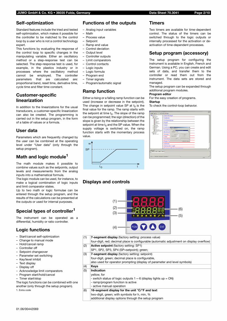
Ramp functionEither a rising or a falling ramp function can beused (increase or decrease in the setpoint).The change in setpoint value SP at t0 is thefinal value for the ramp. The ramp starts withthe setpoint at time t0. The slope of the rampcan be programmed; the sign (direction) of theslope is given by the relationship between thesetpoint at time t0 and the SP value. When thesupply voltage is switched on, the rampfunction starts with the momentary processvalue.
TimersTwo timers are available for time-dependentcontrol. The status of the timers can beswitched through to the logic outputs orinternally processed for the activation or de-activation of time-dependent processes.
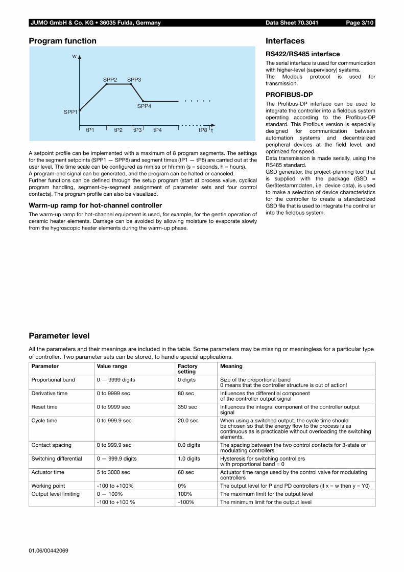
Setup program (accessory)The setup program for configuring theinstrument is available in English, French andGerman. Using a PC, you can create and editsets of data, and transfer them to thecontroller or read them out from theinstrument. The data sets are stored andmanaged.The setup program can be expanded throughadditional program modules.Program editorFor the easy creation of programs.StartupTo check the control-loop behavior.
01.06/00442069
Data Sheet 70.3041JUMO GmbH & Co. KG • 36035 Fulda, Germany Page 3/10
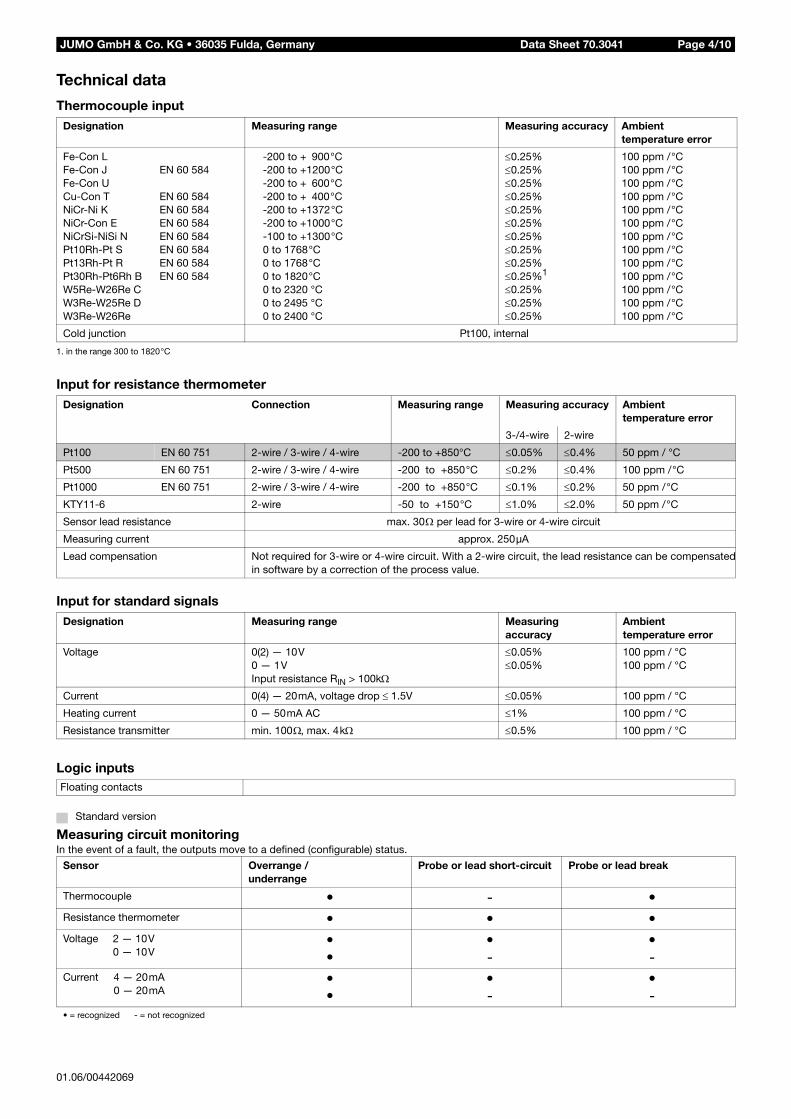
Program function
A setpoint profile can be implemented with a maximum of 8 program segments. The settingsfor the segment setpoints (SPP1 — SPP8) and segment times (tP1 — tP8) are carried out at theuser level. The time scale can be configured as mm:ss or hh:mm (s = seconds, h = hours). A program-end signal can be generated, and the program can be halted or canceled.Further functions can be defined through the setup program (start at process value, cyclicalprogram handling, segment-by-segment assignment of parameter sets and four controlcontacts). The program profile can also be visualized.
Warm-up ramp for hot-channel controllerThe warm-up ramp for hot-channel equipment is used, for example, for the gentle operation ofceramic heater elements. Damage can be avoided by allowing moisture to evaporate slowlyfrom the hygroscopic heater elements during the warm-up phase.
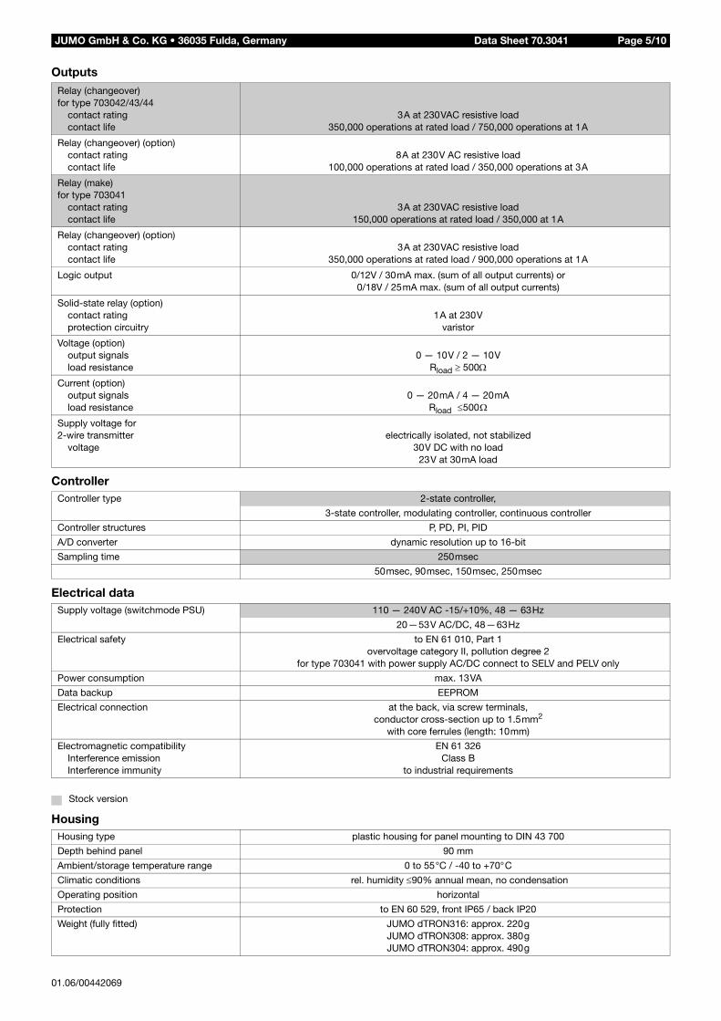
Parameter level
All the parameters and their meanings are included in the table. Some parameters may be missing or meaningless for a particular type of controller. Two parameter sets can be stored, to handle special applications.
Parameter Value range Factory setting
Meaning
Proportional band 0 — 9999 digits 0 digits Size of the proportional band0 means that the controller structure is out of action!
Derivative time 0 to 9999 sec 80 sec Influences the differential componentof the controller output signal
Reset time 0 to 9999 sec 350 sec Influences the integral component of the controller output signal
Cycle time 0 to 999.9 sec 20.0 sec When using a switched output, the cycle time should be chosen so that the energy flow to the process is as continuous as is practicable without overloading the switching elements.
Contact spacing 0 to 999.9 sec 0.0 digits The spacing between the two control contacts for 3-state or modulating controllers
Switching differential 0 — 999.9 digits 1.0 digits Hysteresis for switching controllerswith proportional band = 0
Actuator time 5 to 3000 sec 60 sec Actuator time range used by the control valve for modulating controllers
Working point -100 to +100% 0% The output level for P and PD controllers (if x = w then y = Y0)
Output level limiting 0 — 100% 100% The maximum limit for the output level
-100 to +100 % -100% The minimum limit for the output level
Interfaces
RS422/RS485 interfaceThe serial interface is used for communicationwith higher-level (supervisory) systems.The Modbus protocol is used fortransmission.
PROFIBUS-DPThe Profibus-DP interface can be used tointegrate the controller into a fieldbus systemoperating according to the Profibus-DPstandard. This Profibus version is especiallydesigned for communication betweenautomation systems and decentralizedperipheral devices at the field level, andoptimized for speed.Data transmission is made serially, using theRS485 standard.GSD generator, the project-planning tool thatis supplied with the package (GSD =Gerätestammdaten, i.e. device data), is usedto make a selection of device characteristicsfor the controller to create a standardizedGSD file that is used to integrate the controllerinto the fieldbus system.
Data Sheet 70.3041JUMO GmbH & Co. KG • 36035 Fulda, Germany Page 4/10
Technical data
Thermocouple input
1. in the range 300 to 1820°C
Input for resistance thermometer
Input for standard signals
Logic inputs
Measuring circuit monitoringIn the event of a fault, the outputs move to a defined (configurable) status.
Designation Measuring range Measuring accuracy Ambienttemperature error
Fe-Con LFe-Con JFe-Con UCu-Con TNiCr-Ni KNiCr-Con ENiCrSi-NiSi NPt10Rh-Pt SPt13Rh-Pt RPt30Rh-Pt6Rh BW5Re-W26Re CW3Re-W25Re DW3Re-W26Re
EN 60 584
EN 60 584EN 60 584EN 60 584EN 60 584EN 60 584EN 60 584EN 60 584
-200 to + 900°C-200 to +1200°C-200 to + 600°C-200 to + 400°C-200 to +1372°C-200 to +1000°C-100 to +1300°C0 to 1768°C0 to 1768°C0 to 1820°C0 to 2320 °C0 to 2495 °C0 to 2400 °C
≤0.25%≤0.25%≤0.25%≤0.25%≤0.25%≤0.25%≤0.25%≤0.25%≤0.25%≤0.25%1
≤0.25%≤0.25%≤0.25%
100 ppm /°C100 ppm /°C100 ppm /°C100 ppm /°C100 ppm /°C100 ppm /°C100 ppm /°C100 ppm /°C100 ppm /°C100 ppm /°C100 ppm /°C100 ppm /°C100 ppm /°C
Cold junction Pt100, internal
Designation Connection Measuring range Measuring accuracy Ambienttemperature error
3-/4-wire 2-wire
Pt100 EN 60 751 2-wire / 3-wire / 4-wire -200 to +850°C ≤0.05% ≤0.4% 50 ppm / °C
Pt500 EN 60 751 2-wire / 3-wire / 4-wire -200 to +850°C ≤0.2% ≤0.4% 100 ppm /°C
Pt1000 EN 60 751 2-wire / 3-wire / 4-wire -200 to +850°C ≤0.1% ≤0.2% 50 ppm /°C
KTY11-6 2-wire -50 to +150°C ≤1.0% ≤2.0% 50 ppm /°C
Sensor lead resistance max. 30Ω per lead for 3-wire or 4-wire circuit
Measuring current approx. 250µA
Lead compensation Not required for 3-wire or 4-wire circuit. With a 2-wire circuit, the lead resistance can be compensatedin software by a correction of the process value.
Designation Measuring range Measuring accuracy
Ambienttemperature error
Voltage 0(2) — 10V0 — 1VInput resistance RIN > 100kΩ
≤0.05%≤0.05%
100 ppm / °C100 ppm / °C
Current 0(4) — 20mA, voltage drop ≤ 1.5V ≤0.05% 100 ppm / °C
Heating current 0 — 50mA AC ≤1% 100 ppm / °C
Resistance transmitter min. 100Ω, max. 4kΩ ≤0.5% 100 ppm / °C
Floating contacts
Standard version
Sensor Overrange /underrange
Probe or lead short-circuit Probe or lead break
Thermocouple • - •Resistance thermometer • • •Voltage 2 — 10V
0 — 10V••
•-
•-
Current 4 — 20mA0 — 20mA
••
•-
•-
• = recognized - = not recognized
01.06/00442069
Data Sheet 70.3041JUMO GmbH & Co. KG • 36035 Fulda, Germany Page 5/10
Outputs
Controller
Electrical data
Housing
Relay (changeover) for type 703042/43/44
contact ratingcontact life
3A at 230VAC resistive load350,000 operations at rated load / 750,000 operations at 1A
Relay (changeover) (option)contact ratingcontact life
8A at 230V AC resistive load100,000 operations at rated load / 350,000 operations at 3A
Relay (make)for type 703041
contact ratingcontact life
3A at 230VAC resistive load150,000 operations at rated load / 350,000 at 1A
Relay (changeover) (option)contact ratingcontact life
3A at 230VAC resistive load350,000 operations at rated load / 900,000 operations at 1A
Logic output 0/12V / 30mA max. (sum of all output currents) or0/18V / 25mA max. (sum of all output currents)
Solid-state relay (option)contact ratingprotection circuitry
1A at 230Vvaristor
Voltage (option)output signalsload resistance
0 — 10V / 2 — 10VRload ≥ 500Ω
Current (option)output signalsload resistance
0 — 20mA / 4 — 20mARload ≤500Ω
Supply voltage for2-wire transmitter
voltageelectrically isolated, not stabilized
30V DC with no load23V at 30mA load
Controller type 2-state controller,
3-state controller, modulating controller, continuous controller
Controller structures P, PD, PI, PID
A/D converter dynamic resolution up to 16-bit
Sampling time 250msec
50msec, 90msec, 150msec, 250msec
Supply voltage (switchmode PSU) 110 — 240V AC -15/+10%, 48 — 63Hz
20—53V AC/DC, 48—63Hz
Electrical safety to EN 61 010, Part 1overvoltage category II, pollution degree 2
for type 703041 with power supply AC/DC connect to SELV and PELV only
Power consumption max. 13VA
Data backup EEPROM
Electrical connection at the back, via screw terminals,conductor cross-section up to 1.5mm2
with core ferrules (length: 10mm)
Electromagnetic compatibilityInterference emissionInterference immunity
EN 61 326Class B
to industrial requirements
Stock version
Housing type plastic housing for panel mounting to DIN 43 700
Depth behind panel 90 mm
Ambient/storage temperature range 0 to 55°C / -40 to +70°C
Climatic conditions rel. humidity ≤90% annual mean, no condensation
Operating position horizontal
Protection to EN 60 529, front IP65 / back IP20
Weight (fully fitted) JUMO dTRON316: approx. 220gJUMO dTRON308: approx. 380gJUMO dTRON304: approx. 490g
01.06/00442069
Data Sheet 70.3041JUMO GmbH & Co. KG • 36035 Fulda, Germany Page 6/10
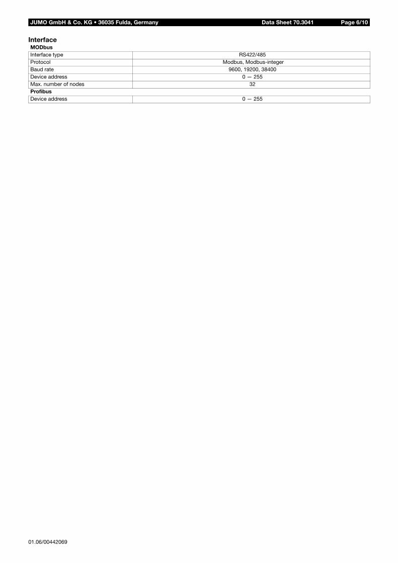
InterfaceMODbusInterface type RS422/485Protocol Modbus, Modbus-integerBaud rate 9600, 19200, 38400Device address 0 — 255Max. number of nodes 32ProfibusDevice address 0 — 255
01.06/00442069
Data Sheet 70.3041JUMO GmbH & Co. KG • 36035 Fulda, Germany Page 7/10
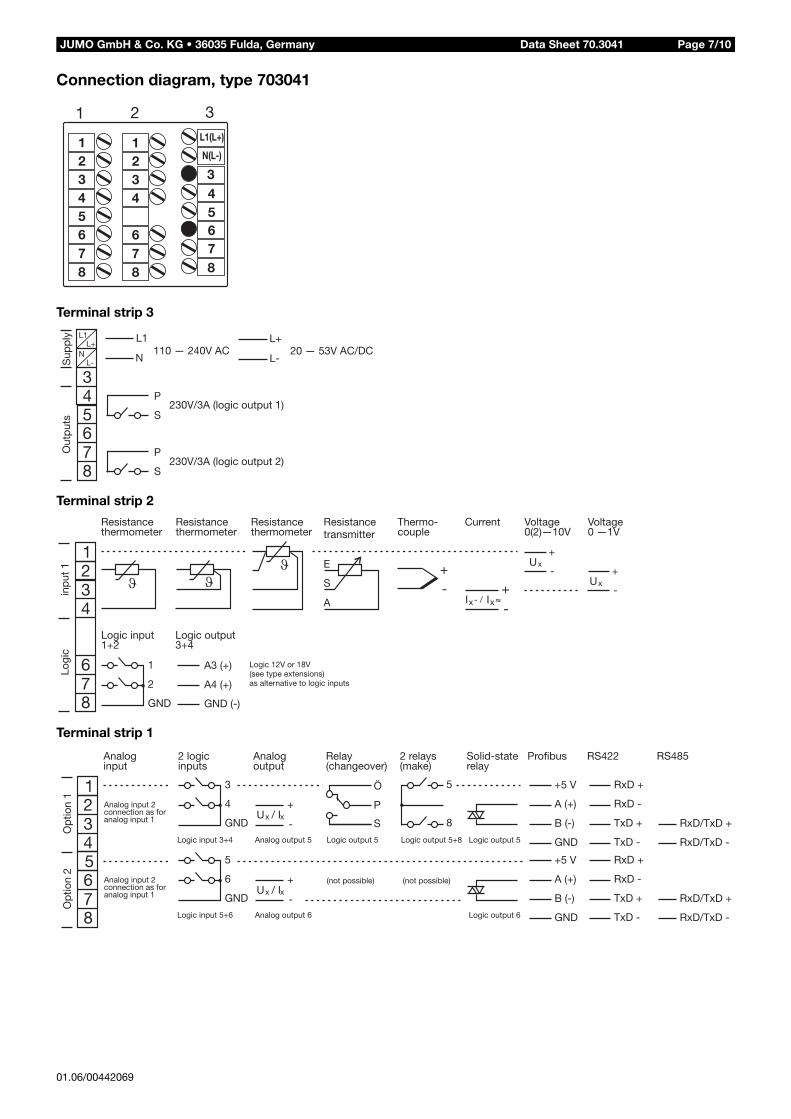
Connection diagram, type 703041
Terminal strip 3
Terminal strip 2
Terminal strip 1
5678
678
1
1
234
1
2
234
8
34
67
3
5
L1(L+)
N(L-)
01.06/00442069
Data Sheet 70.3041JUMO GmbH & Co. KG • 36035 Fulda, Germany Page 8/10
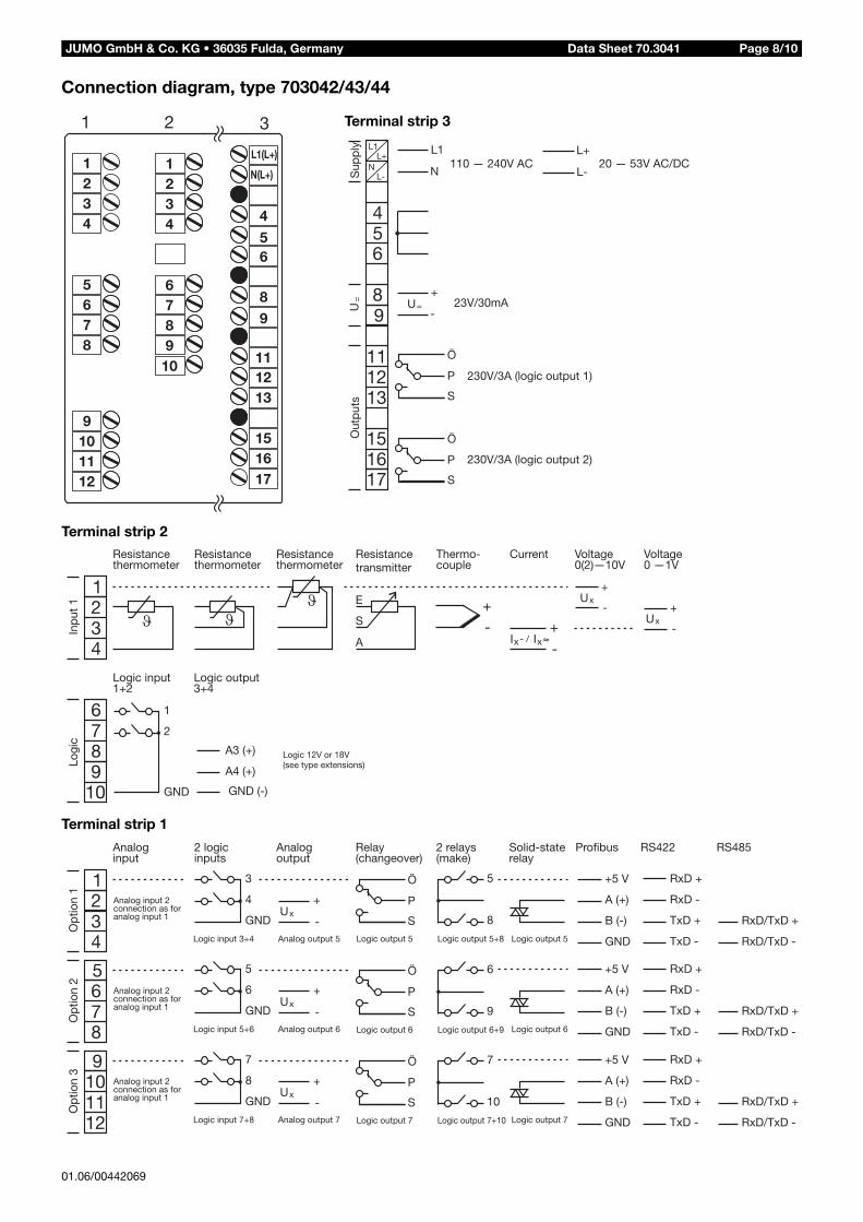
Connection diagram, type 703042/43/44
Terminal strip 2
Terminal strip 1
1
1234
2
1234
5678
6789
10
9101112
3
4
L1(L+)
56
89
111213
151617
N(L+)
L1
N
L+
L-
456
8
110 — 240V AC 20 — 53V AC/DC
230V/3A (logic output 1)
230V/3A (logic output 2)
Sup
ply
Out
put
s
9
1211
13
151617
Ö
P
S
Ö
P
S
+
-U= 23V/30mAU
=
L1L+
NL-
Terminal strip 3
01.06/00442069

01.06/00442069
Data Sheet 70.3041JUMO GmbH & Co. KG • 36035 Fulda, Germany Page 9/10
DimensionsType 703041 Type 703042/43
Type 703044
Close mountingMinimum spacing of panel cut-outs
Type horizontal vertical
without setup connector:
703041703042 (portrait format)703043 (landscape fmt.)703044
11mm11mm30mm11mm
30mm30mm11mm30mm
with setup connector (see arrow):
703041703042 (portrait format)703043 (landscape fmt.)703044
11mm11mm65mm11mm
65mm65mm11mm65mm
JUMO GmbH & Co. KG • 36035 Fulda, Germany010101
01.06/00442069
Data Sheet 70.3041 Page 10/10
= stock versions
Scope of delivery: - 1 controller- 1 seal- mounting brackets- 1 Operating Instructions B70.3041.1- 1 Installation Instructions B70.3041.4- 1 mini-CD with demo setup software, comprehensive operating manual and additional documentation
(software can be enabled for a charge; also for download at www.JUMO.net)
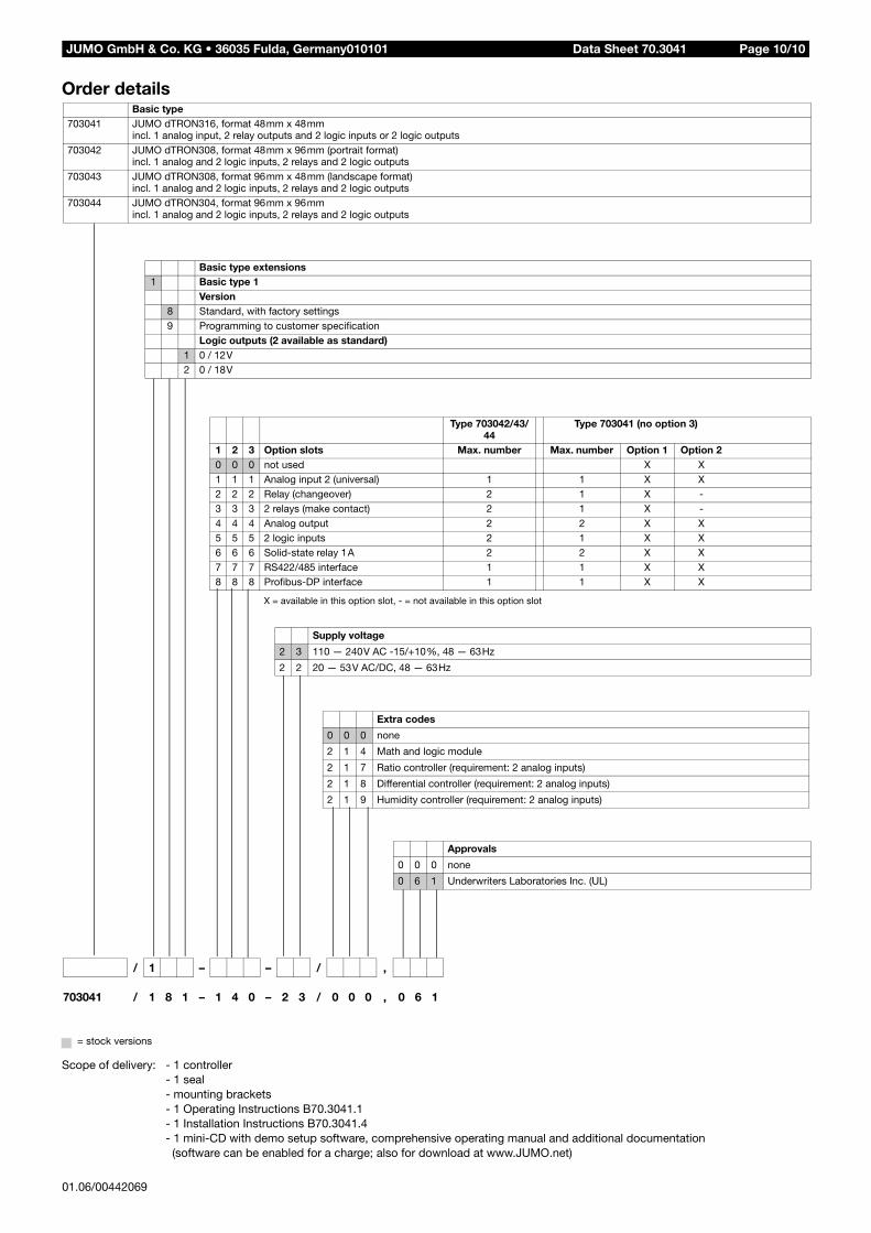
Order details
Basic type extensions1 Basic type 1
Version8 Standard, with factory settings9 Programming to customer specification
Logic outputs (2 available as standard)1 0 / 12V2 0 / 18V
X = available in this option slot, - = not available in this option slot
Type 703042/43/44
Type 703041 (no option 3)
1 2 3 Option slots Max. number Max. number Option 1 Option 20 0 0 not used X X1 1 1 Analog input 2 (universal) 1 1 X X2 2 2 Relay (changeover) 2 1 X -3 3 3 2 relays (make contact) 2 1 X -4 4 4 Analog output 2 2 X X5 5 5 2 logic inputs 2 1 X X6 6 6 Solid-state relay 1A 2 2 X X7 7 7 RS422/485 interface 1 1 X X8 8 8 Profibus-DP interface 1 1 X X
Supply voltage
2 3 110 — 240V AC -15/+10%, 48 — 63Hz
2 2 20 — 53V AC/DC, 48 — 63Hz
/ 1 – – / ,
703041 / 1 8 1 – 1 4 0 – 2 3 / 0 0 0 , 0 6 1
Basic type 703041 JUMO dTRON316, format 48mm x 48mm
incl. 1 analog input, 2 relay outputs and 2 logic inputs or 2 logic outputs703042 JUMO dTRON308, format 48mm x 96mm (portrait format)
incl. 1 analog and 2 logic inputs, 2 relays and 2 logic outputs703043 JUMO dTRON308, format 96mm x 48mm (landscape format)
incl. 1 analog and 2 logic inputs, 2 relays and 2 logic outputs703044 JUMO dTRON304, format 96mm x 96mm
incl. 1 analog and 2 logic inputs, 2 relays and 2 logic outputs
Extra codes
0 0 0 none
2 1 4 Math and logic module
2 1 7 Ratio controller (requirement: 2 analog inputs)
2 1 8 Differential controller (requirement: 2 analog inputs)
2 1 9 Humidity controller (requirement: 2 analog inputs)
Approvals
0 0 0 none
0 6 1 Underwriters Laboratories Inc. (UL)