JULY 2014 - Iowa Stray Voltage · PDF fileJULY 2014. 2 | I O WA STRAY ... Loose neutral wire...
28
IOWA STRAY VOLTAGE GUIDE A Guide Addressing Stray Voltage Concerns This document supplements the United States Department of Agriculture Hand- book 696 titled “Effects of Electrical Voltage/Current on Farm Animals: How to Detect and Remedy Problems” December 1991, commonly referred to as the Red Book. Iowa Association of Electric Cooperatives The following organizations developed this guide. JULY 2014
Transcript of JULY 2014 - Iowa Stray Voltage · PDF fileJULY 2014. 2 | I O WA STRAY ... Loose neutral wire...
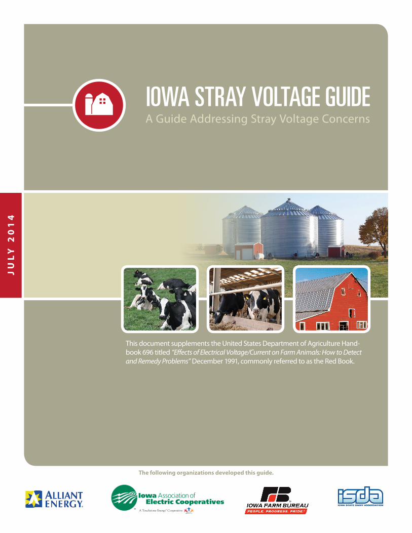
IOWA STRAY VOLTAGE GUIDEA Guide Addressing Stray Voltage Concerns
This document supplements the United States Department of Agriculture Hand-book 696 titled “Effects of Electrical Voltage/Current on Farm Animals: How to Detect and Remedy Problems” December 1991, commonly referred to as the Red Book.
Iowa Association of Electric Cooperatives
The following organizations developed this guide.
JU
LY
20
14
2 | I O W A S T R A Y V O L T A G E G U I D E
Sponsoring Organizations :
Alliant Energy
Iowa Association of Electric Cooperatives
Iowa Cattlemen’s Association
Iowa Energy Center
Iowa Farm Bureau Federation
Iowa Institute of Cooperatives
Iowa State Dairy Association
Unless stated otherwise, permission is granted to reproduce these materials if the content is not altered. Reproduction via copy machine or other copy technology is permissible. Also, the material can be reproduced in newsletters and other distribution methods. If the materials are reproduced in a newsletter, magazine, web site or other method of distribution, please notify the Iowa Association of Electric Cooperatives at 515.276.5350. This notification is for informational purposes to track the usage of our materials.
Disclaimer
The information in this guide is intended for use as educational material to assist utility representatives, farmers and their advisors to understand processes and procedures that can be used to resolve stray voltage concerns. Identification and diagnosis of stray voltage problems can sometimes be difficult and requires electrical expertise. Working with electrical systems can be dangerous. Voltages that cause stray voltage problems are normally so low they cannot be detected without special instruments. A possible hazard to life exists if an electrical shock can actually be felt or if animals are knocked down. The device or electric circuit responsible for the shock should be disconnected by unplugging the device or de-energizing the circuit at the service panel. The situation should be examined by an electrical professional as soon as possible.
This document is not meant to provide legal advice or establish an attorney-client relationship. Consult your legal representative and the responsible state or federal agencies regarding your specific situation before utilizing these materials in a legal proceeding. Reasonable efforts have been made to ensure the accuracy of the information contained in this guide; however, the nature and content of the guide are subject to changes in the law and in scientific advancement. The effect of future regulatory and judicial developments may alter the interpretation and effect of the recommended processes and procedures discussed in this handbook. The utilization of these materials by any person represents an agreement to hold harmless the authors, and the sponsoring organizations for any liability, claims, damages, or expenses that may be incurred by any person as a result of reference or reliance on the information contained in this guide.
PREFACE
Iowa Association of Electric Cooperatives
I O W A S T R A Y V O L T A G E G U I D E | 3
Introduction . . . . . . . . . . . . . . . . . . . . . . . . . . . . . . . . . . . . . . . . . . . . . . . . . . . . . . . 4
Iowa Stray Voltage Flowchart . . . . . . . . . . . . . . . . . . . . . . . . . . . . . . . . . . . . . . . . . . . . 5
Common Causes of Stray Voltage . . . . . . . . . . . . . . . . . . . . . . . . . . . . . . . . . . . . . . . . . 6
On-Farm . . . . . . . . . . . . . . . . . . . . . . . . . . . . . . . . . . . . . . . . . . . . . . . . . . . . . . . . 6
Off-Farm . . . . . . . . . . . . . . . . . . . . . . . . . . . . . . . . . . . . . . . . . . . . . . . . . . . . . . . . 6
Farm Wiring Checklist . . . . . . . . . . . . . . . . . . . . . . . . . . . . . . . . . . . . . . . . . . . . . . . . . 7
Proper Farm Wiring Summary . . . . . . . . . . . . . . . . . . . . . . . . . . . . . . . . . . . . . . . . . . . . 8
Frequently Asked Questions . . . . . . . . . . . . . . . . . . . . . . . . . . . . . . . . . . . . . . . . . . . 9-11
Stray Voltage Meter . . . . . . . . . . . . . . . . . . . . . . . . . . . . . . . . . . . . . . . . . . . . . . . . . 12
Hiring an Electrician for On-Farm Wiring . . . . . . . . . . . . . . . . . . . . . . . . . . . . . . . . . . . 13
Utility Contact Information . . . . . . . . . . . . . . . . . . . . . . . . . . . . . . . . . . . . . . . . . . . . 14
Information about Biosecurity Protocols . . . . . . . . . . . . . . . . . . . . . . . . . . . . . . . . . . . 15
Other Biosecurity Resources . . . . . . . . . . . . . . . . . . . . . . . . . . . . . . . . . . . . . . . . . . . 15
All species: . . . . . . . . . . . . . . . . . . . . . . . . . . . . . . . . . . . . . . . . . . . . . . . . . . . . . . 15
Swine: . . . . . . . . . . . . . . . . . . . . . . . . . . . . . . . . . . . . . . . . . . . . . . . . . . . . . . . . . 15
Dairy: . . . . . . . . . . . . . . . . . . . . . . . . . . . . . . . . . . . . . . . . . . . . . . . . . . . . . . . . . 15
Cattle: . . . . . . . . . . . . . . . . . . . . . . . . . . . . . . . . . . . . . . . . . . . . . . . . . . . . . . . . . 15
Poultry: . . . . . . . . . . . . . . . . . . . . . . . . . . . . . . . . . . . . . . . . . . . . . . . . . . . . . . . . 15
Testing Procedures . . . . . . . . . . . . . . . . . . . . . . . . . . . . . . . . . . . . . . . . . . . . . . . . . . 16
Phase I Protocol . . . . . . . . . . . . . . . . . . . . . . . . . . . . . . . . . . . . . . . . . . . . . . . . . . . 16
Phase II Protocol. . . . . . . . . . . . . . . . . . . . . . . . . . . . . . . . . . . . . . . . . . . . . . . . . . . 16
Load Box Test (LB test) . . . . . . . . . . . . . . . . . . . . . . . . . . . . . . . . . . . . . . . . . . . . . . . 16
Secondary Neutral Voltage Drop Test (SNVD test) . . . . . . . . . . . . . . . . . . . . . . . . . . . . . . 17
Signature Test . . . . . . . . . . . . . . . . . . . . . . . . . . . . . . . . . . . . . . . . . . . . . . . . . . . . 18
Primary Profile Test . . . . . . . . . . . . . . . . . . . . . . . . . . . . . . . . . . . . . . . . . . . . . . . . . 18
“24-Hour” Test . . . . . . . . . . . . . . . . . . . . . . . . . . . . . . . . . . . . . . . . . . . . . . . . . . . . 18
Appendix A Sample Forms . . . . . . . . . . . . . . . . . . . . . . . . . . . . . . . . . . . . . . . . . . . . 19-24
Appendix B Model Report for Utilities to Use with Farmers . . . . . . . . . . . . . . . . . . . . . . . . . . 25
Appendix C List of Reference Materials for Utilities and Farmers . . . . . . . . . . . . . . . . . . . . . 26-27
TABLE OF CONTENTS

4 | I O W A S T R A Y V O L T A G E G U I D E
The Iowa Stray Voltage Guide outlines the steps farmers, electricians, utilities and their advisors can take to discover and resolve stray voltage concerns on livestock farms. When farmers and utility companies can work together, stray voltage concerns are more likely to be satisfactorily resolved. This compilation of information was a collaborative effort of Alliant Energy, Iowa Association of Electric Cooperatives, Iowa Farm Bureau Federation, and Iowa State Dairy Association.
The contact information for each utility is included for easy reference. Farmers and utilities may also include their advisors, such as veterinarians or electricians, in this process to put additional knowledge and experience to bear on resolving the issues.
The information included in this guide is intended to provide a base level of knowledge for those who are concerned about whether the animals on a livestock farm are experiencing a level of stray voltage which may be impacting animal behavior, performance or production. The processes outlined in this guide provide a systematic method for determining whether stray voltage might be causing a problem and how to best address the problem. While stray voltage may never be completely eliminated, steps can be taken to reduce stray voltage to acceptable levels.
INTRODUCTIONThe guide includes a list of common causes and a farm wiring checklist to address possible causes and ways to avoid on-farm stray voltage. It also goes through what the farmer and utility should expect when conducting a stray voltage investigation, including the proper testing procedures for stray voltage. Although this guide is focused on cattle and dairy farms, the processes and procedures are relevant to all types of livestock and livestock housing facilities.
The sponsoring organizations used several sources of information as the technical basis for the guide. The principal foundation for the processes and procedures was the U.S. Department of Agriculture Handbook, “Effects of Electrical Voltage/Current on Farm Animals: How to Detect and Remedy Problems”, but the groups also incorporated appropriate information from Alliant Energy’s stray voltage program, the Wisconsin Public Service Commission and the Midwest Rural Energy Council. The Alliant Energy processes and procedures were developed based on the stray voltage materials developed by the Wisconsin Public Service Commission, and several other Iowa utilities use a similar approach.
The USDA Handbook examines:
The history of stray voltage/current problems on farms.
The physical and electrical sources of stray voltage/current phenomena.
The physiological and behavioral basis for losses in milk production.
Methods for identifying and detecting stray voltage/current problems.
Methods for mitigating such problems.
Areas where further research may be warranted.
A full list of resources and reference material can be found at the end of this guide.

I O W A S T R A Y V O L T A G E G U I D E | 5
• Utility and farmer review report and discuss options of reducing on-farm contribution
• Utility testing complete
• Utility and farmer discuss options for future monitoring or other actions
• Utility takes action to reduce its contribution to below 0.5 volt at the animal contact point
No
• Utility and farmer review results from Phase I testing
• Phase II testing begins (See page 16 of this guide)
• Utility returns to farm to retrieve equipment and data from Phase II testing
YesNo
Is utilitycontributing
0.5 or more volt at the animal contact point?
• Utility unaware of farmer’s stray voltage concerns
• Utility performs no on-farm stray voltage testing
• Farmer explains biosecurity protocols and policies
• Date & time set for utility site visit for stray voltage investigation2
• Utility visits farm to begin Phase I testing (See page 16 of this guide)
• Utility returns to farm to retrieve equipment and data from Phase I testing
• Utility explains stray voltage investigation protocols and policies
• Farmer explains any investigation work done or completed by others
1 This is not a recommended path under the Iowa Stray Voltage Guide.2 The utility or the farmer may use experts as necessary during the process.
YesNo1
YesNo
CallElectricUtility?
Is an investigation
necessary?
FARMER HAS CONCERNS WITH STRAY VOLTAGE
Is stray voltage level
above 0.5 volt at the animal contact point?
Yes
6 | I O W A S T R A Y V O L T A G E G U I D E
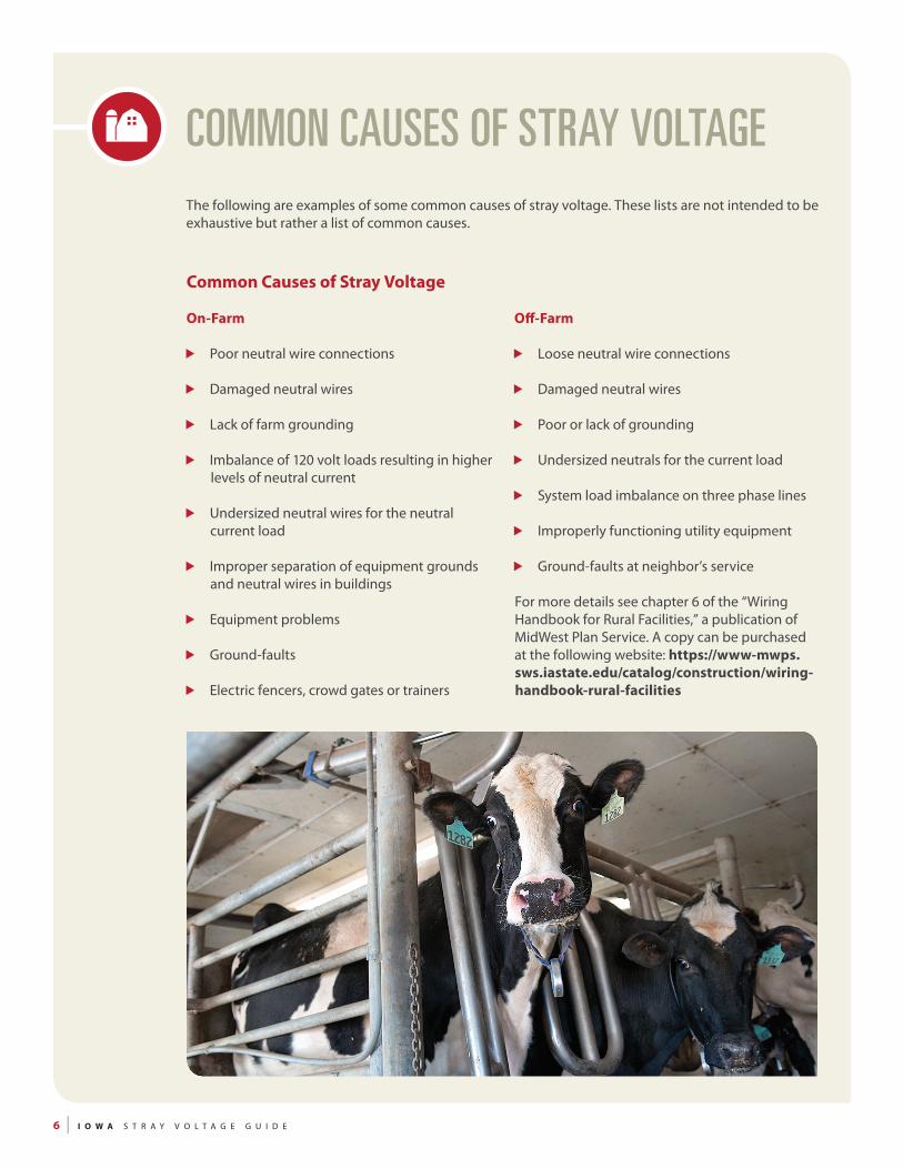
COMMON CAUSES OF STRAY VOLTAGE
Common Causes of Stray Voltage
On-Farm
Poor neutral wire connections
Damaged neutral wires
Lack of farm grounding
Imbalance of 120 volt loads resulting in higher levels of neutral current
Undersized neutral wires for the neutral current load
Improper separation of equipment grounds and neutral wires in buildings
Equipment problems
Ground-faults
Electric fencers, crowd gates or trainers
Off-Farm
Loose neutral wire connections
Damaged neutral wires
Poor or lack of grounding
Undersized neutrals for the current load
System load imbalance on three phase lines
Improperly functioning utility equipment
Ground-faults at neighbor’s service
For more details see chapter 6 of the “Wiring Handbook for Rural Facilities,” a publication of MidWest Plan Service. A copy can be purchased at the following website: https://www-mwps.sws.iastate.edu/catalog/construction/wiring-handbook-rural-facilities
The following are examples of some common causes of stray voltage. These lists are not intended to be exhaustive but rather a list of common causes.
I O W A S T R A Y V O L T A G E G U I D E | 7
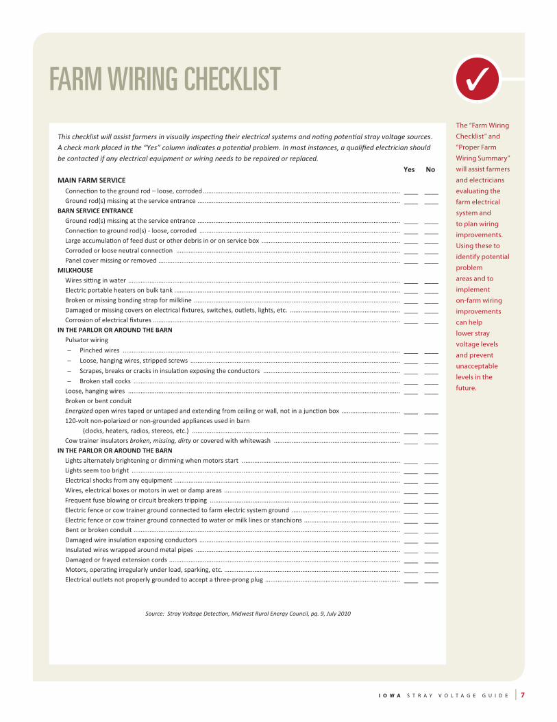
FARM WIRING CHECKLISTThe “Farm Wiring Checklist” and “Proper Farm Wiring Summary” will assist farmers and electricians evaluating the farm electrical system and to plan wiring improvements. Using these to identify potential problem areas and to implement on-farm wiring improvements can help lower stray voltage levels and prevent unacceptable levels in the future.
8 | I O W A S T R A Y V O L T A G E G U I D E
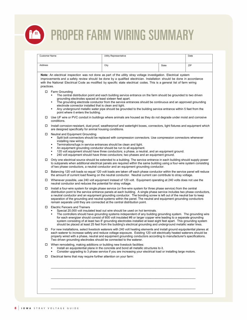
PROPER FARM WIRING SUMMARYSTRAY VOLTAGE- PROPER FARM WIRING SUMMARY
Customer Name Utility Representative Date
Address City State ZIP
Note: An electrical inspection was not done as part of the utility stray voltage investigation. Electrical system improvements and a safety review should be done by a qualified electrician. Installation should be done in accordance with the National Electrical Code as modified by specific state electrical codes. This is a general list of farm wiring practices.
Farm Grounding The central distribution point and each building service entrance on the farm should be grounded to two driven
grounding electrodes spaced at least sixteen feet apart. The grounding electrode conductor from the service entrances should be continuous and an approved grounding
electrode connector installed that is clean and tight. Any underground metallic water pipe should be grounded to the building service entrance within 5 feet from the
point where it enters the building.
Use UF wire or PVC conduit in buildings where animals are housed as they do not degrade under moist and corrosive conditions.
Install corrosion-resistant, dust proof, weatherproof and watertight boxes, connectors, light fixtures and equipment which are designed specifically for animal housing conditions.
Neutral and Equipment Grounding Split bolt connectors should be replaced with compression connectors. Use compression connectors whenever
installing new wiring. Terminations/lugs in service entrances should be clean and tight. An equipment grounding conductor should be run to all equipment. 120 volt equipment should have three conductors; a phase, a neutral, and an equipment ground. 240 volt equipment should have three conductors; two phases and an equipment ground.
Only one electrical source should be extended to a building. The service entrance in each building should supply power to subpanels when additional electrical panels are required within the same building using a four-wire system consisting of two phase conductors, a neutral conductor and an equipment grounding conductor.
Balancing 120 volt loads so equal 120 volt loads are taken off each phase conductor within the service panel will reduce the amount of current load flowing on the neutral conductor. Neutral current can contribute to stray voltage.
Whenever possible, use 240 volt equipment instead of 120 volt. Equipment operating at 240 volts does not use the neutral conductor and reduces the potential for stray voltage.
Install a four-wire system for single phase service (or five-wire system for three phase service) from the central distribution point to the service entrance panels at each building. A single phase service includes two phase conductors, a neutral conductor and an equipment grounding conductor. The bonding screw is left out of the neutral bar to keep separation of the grounding and neutral systems within the panel. The neutral and equipment grounding conductors remain separate until they are connected at the central distribution point.
Electric Fencers and Trainers Special 20,000 volt insulated lead out wire should be used on hot terminals. The controllers should have grounding systems independent of any building grounding system. The grounding wire
for each energizer should consist of 600 volt insulated #8 or larger copper wire leading to a separate grounding system consisting of at least two 8' grounding electrodes installed at least eight feet apart. This grounding system should be placed at least 25 feet from the building's electrical grounding and underground metallic water lines.
For new installations, select livestock waterers with 240 volt heating elements and install ground equipotential planes at each waterer to increase safety and reduce voltage exposure. Existing 120 volt electrically heated waterers should be properly wired with a phase, neutral and equipment grounding conductors according to manufacturer's specifications. Two driven grounding electrodes should be connected to the waterer.
When remodeling, making additions or building new livestock facilities: Install an equipotential plane in the concrete and bond all metallic structures to it. Consider upgrading to 3 phase service if you are increasing your electrical load or installing large motors.
Electrical items that may require further attention on your farm: _______________________________________________________________________________________ _______________________________________________________________________________________ _______________________________________________________________________________________
I O W A S T R A Y V O L T A G E G U I D E | 9
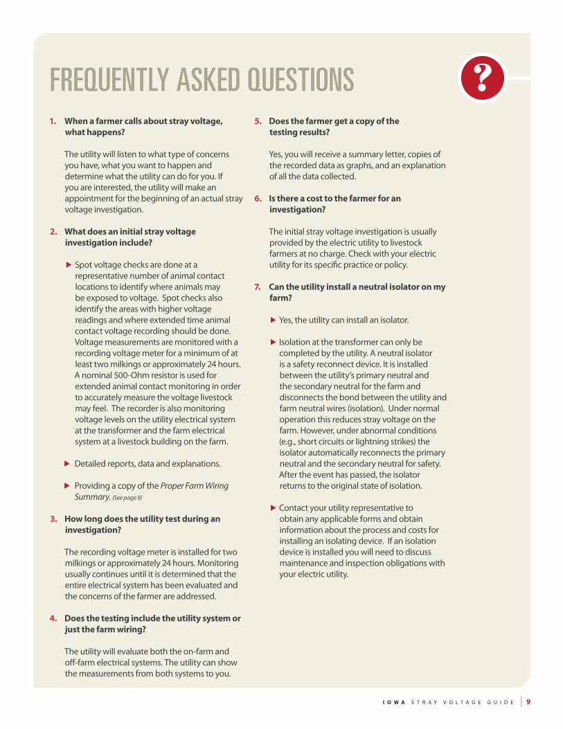
1. When a farmer calls about stray voltage, what happens?
The utility will listen to what type of concerns you have, what you want to happen and determine what the utility can do for you. If you are interested, the utility will make an appointment for the beginning of an actual stray voltage investigation.
2. What does an initial stray voltage investigation include?
Spot voltage checks are done at a representative number of animal contact locations to identify where animals may be exposed to voltage. Spot checks also identify the areas with higher voltage readings and where extended time animal contact voltage recording should be done. Voltage measurements are monitored with a recording voltage meter for a minimum of at least two milkings or approximately 24 hours. A nominal 500-Ohm resistor is used for extended animal contact monitoring in order to accurately measure the voltage livestock may feel. The recorder is also monitoring voltage levels on the utility electrical system at the transformer and the farm electrical system at a livestock building on the farm.
Detailed reports, data and explanations.
Providing a copy of the Proper Farm Wiring Summary. (See page 8)
3. How long does the utility test during an investigation?
The recording voltage meter is installed for two milkings or approximately 24 hours. Monitoring usually continues until it is determined that the entire electrical system has been evaluated and the concerns of the farmer are addressed.
4. Does the testing include the utility system or just the farm wiring?
The utility will evaluate both the on-farm and off-farm electrical systems. The utility can show the measurements from both systems to you.
FREQUENTLY ASKED QUESTIONS5. Does the farmer get a copy of the
testing results?
Yes, you will receive a summary letter, copies of the recorded data as graphs, and an explanation of all the data collected.
6. Is there a cost to the farmer for an investigation?
The initial stray voltage investigation is usually provided by the electric utility to livestock farmers at no charge. Check with your electric utility for its specific practice or policy.
7. Can the utility install a neutral isolator on my farm?
Yes, the utility can install an isolator.
Isolation at the transformer can only be completed by the utility. A neutral isolator is a safety reconnect device. It is installed between the utility’s primary neutral and the secondary neutral for the farm and disconnects the bond between the utility and farm neutral wires (isolation). Under normal operation this reduces stray voltage on the farm. However, under abnormal conditions (e.g., short circuits or lightning strikes) the isolator automatically reconnects the primary neutral and the secondary neutral for safety. After the event has passed, the isolator returns to the original state of isolation.
Contact your utility representative to obtain any applicable forms and obtain information about the process and costs for installing an isolating device. If an isolation device is installed you will need to discuss maintenance and inspection obligations with your electric utility.

10 | I O W A S T R A Y V O L T A G E G U I D E
8. What happens after initial testing?
After testing is completed, the measured animal contact voltages are reviewed to determine further actions. While stray voltage can never be completely eliminated, steps can be taken to reduce the levels.
Stray voltage can come from on-farm or off-farm sources. If a voltage difference of 1.0 volt AC or more exists between animal contact points (measured with a nominal 500 Ohm resistor in the circuit) it is recommended that action be taken to reduce this voltage. The utility will take action if 0.5 volt or greater is coming from off-farm sources and the farmer is encouraged to take action if the on-farm contribution is 0.5 volt or greater. If the utility distribution system contributes 0.5 volt or more to the animal contact voltage as determined by a load test of 20 kW (approximately 27 hp) of 240 volt load, the utility will take steps to address the issue until the utility’s contribution to animal contact voltages is less than 0.5 volt. This level is used so proactive measures can be taken to prevent animal avoidance behavior and animal production losses.
If animal contact voltages are due to the wiring on your farm, consult with your electrician and utility representative to resolve problems or improve the farm wiring system.
9. Is there any follow-up testing?
Your utility representative can also perform follow-up testing to determine the effectiveness of any modifications. He or she will also consult on new construction projects or the installation of equipotential planes.
10. Can farmers perform their own stray voltage testing?
There are certain tests of the utility electric system that can only be completed by the electric utility. The Midwest Rural Energy Council is a good source of information related to stray
FREQUENTLY ASKED QUESTIONSvoltage. They have published a document titled
“Stray Voltage Detection: A Self-Help Guide”. This publication is intended to give you a basic understanding of stray voltage, some of its common sources, how to determine if harmful levels exist on your farm and when and how to call for assistance to help reduce stray voltage levels. This document is not intended to make you a stray voltage expert, but should provide you with the information necessary to safely determine if a problematic level of stray voltage is present on your farm at locations that are accessible to your livestock. This publication is specifically oriented toward the dairy farmer; however, most of the information provided is applicable to all livestock operations. A copy of this publication can be found on the web at: fyi.uwex.edu/mrec/files/2011/02/svd1.pdf
11. How might the Iowa Utilities Board be involved in a stray voltage investigation?
The Iowa Utilities Board, a division of the Iowa Department of Commerce, regulates Iowa’s utility companies. This regulatory authority encompasses certain power quality issues, such as stray voltage. If you have an issue that cannot be resolved by the parties, you may file a complaint with the Utilities Board; however, the Board does not have the authority to award damages in these instances. The following link on their website will give you more information about filing with the Board: www.state.ia.us/government/com/util/complaints/index.html
12. What should I consider when selecting a stray voltage investigator?
Your electric utility offers stray voltage information and some testing at no charge. Please contact your utility for more information about its specific policy and procedures for testing. A list of electric utility contacts is on page 14. When selecting a stray voltage investigator, care should be taken to ensure the investigator has the training and expertise necessary to help you identify the cause of the stray voltage problem. You may want to ask where they received their training and get referrals from

I O W A S T R A Y V O L T A G E G U I D E | 11
other farmers. One such training program is through the University of Wisconsin Extension Service (See: fyi.uwex.edu/mrec/mrec-programs-and-conferences/). For best results in solving the problem, you should ask the investigator to follow the procedures and protocols outlined in this guide.
There are also well recognized training and certification programs offered in Wisconsin and Michigan. More information can be found at the Wisconsin Department of Agriculture, Trade and Consumer Protection (See: datcp.wi.gov/Farms/Wisconsin_Farm_Center/Farm_Rewiring/Stray_Voltage/index.aspx) or the Michigan Agricultural Energy Council (See: maec.msu.edu/training.htm).
13. I am considering expanding my livestock operations. Are there any resources to help me plan for this?
Your electrician and utility representative are important resources to involve early in the planning process.
A significant amount of Iowa’s farms are served by single phase lines. Additions of motorized equipment or farm expansions may add to the electrical requirements of the farm. The utility service should be evaluated to determine the impact of this new electrical load on stray voltage levels. Using recommended farm wiring practices that minimize stray voltage is important. The utility must also plan for increased loads on their system to prevent stray voltage from becoming a problem. This may include additional cost for upgrading the utility system neutral or extending three-phase.
Additionally, the Midwest Rural Energy Council has a good publication titled
“Planning Electrical Systems for Dairy Expansions”. A copy of this publication can be found on the web at: fyi.uwex.edu/mrec/files/2011/02/pes2.pdf. Another resource is the Coalition to Support Iowa’s Farmers 1-800-932-2436 or: www.supportfarmers.com/
14. Are there any resources to help me plan for the installation or operation of cow trainers, crowd gates and electric fences?
Yes, the Midwest Rural Energy Council has a publication titled “Installation and Operation of Electric Fences, Cow Trainers and Crowd Gates”.
This publication can be found on the web at: fyi.uwex.edu/mrec/files/2011/02/ElectricFencers_MREC_051.pdf
15. I am considering the installation of wind energy on my farm. Are there any considerations related to stray voltage for adding wind energy to my farm?
The Midwest Rural Energy Council has a publication titled “Wind Turbines and Farm Stray Voltage”. A copy of this publication can be found on the web at: fyi.uwex.edu/mrec/files/2014/03/WindTurbinesStrayVoltage-pages.pdf
While the above information applies to wind energy, it would likely also apply to solar, methane digesters or other on-farm generation sources.
16. If I am considering the installation of a generation resource (e.g., wind, solar, methane digester, etc.) do I need to contact my electric utility?
Yes, it is always advisable to contact your electric utility when considering the purchase of any generation for your farm. Your electric utility is a valuable source of information related to your decision so contact them when considering investing in any generation resource. Iowa law requires customers to notify their electric utility at least 30 days prior to the operation of your generation. See: Iowa Code Section 476.6(A). Your electric utility has a written policy for purchasing any excess electricity you may generate.

12 | I O W A S T R A Y V O L T A G E G U I D E
The following is a guide for the proper installation of a stray voltage meter.STRAY VOLTAGE METER
Close up ofWater line clamp
Use a #12 Wire
An inexpensive and effective way to monitor the level of stray voltage in the cow contact areas is to install a permanent stray voltage meter. There are several brands of meters on the market that are currently being used to monitor stray voltage. ALL are effective, IF they are installed and maintained properly. The illustration shows the correct way to install a stray voltage meter in a barn.
Even a good meter is not useful, if it is not checked or maintained. ALL meter connections must be kept clean and tight to get good voltage readings. Routinely check the input voltage terminals, water line clamp, and wire to the copper plate. Breaks in the wire, corrosion, and excessive dirt build up will severely impact your voltage readings. You may want to keep a log of voltage readings from your meter for future reference. Follow your meter manual instructions for operation and battery checks.
Stray Voltage Meter. Mount the stray voltage meter (1) in a clean, dry and easily accessible location for routine checking.
Water Line Clamp. Connect one end of a #12 solid “USE” (Underground Service Entrance) conductor or a “XHHW” insulated wire to the water line clamp (2) and other end to one of the input voltage terminals on the meter (See close-
up). Brush the area where the water line clamp connects with the water pipe with a wire brush to insure the clamp makes good contact.
Instructions
Copper Plate. Solder a wire to connect the water line to a 4” x 4” copper plate. Be sure to use “wire” solder and not plumbing solder.
Position the Plate. Embed the plate 1” to 1-1/2” deep into the concrete and remember to position the copper plate in the center of the rear hoof area away from the metal piping.
Groove for Lead Wire. Prepare a groove (4) to embed the lead wire.
PVC Conduit. Put a piece of rigid PVC tubing into the cement (5) to protect the lead wire where it comes out of the cement. Extend the PVC tubing at least four feet up from the floor. Also protect the lead wire along with any other surfaces that it may be exposed to rough treatment.
Grout Cover. After positioning the plate and wire, cover the plate and lead wire with grout (3 & 4).
Meter Operation. Refer to your meter manual for operation and battery information.
Close up ofWater line clamp
Use a #12 Wire

I O W A S T R A Y V O L T A G E G U I D E | 13
HIRING AN ELECTRICIAN FOR ON-FARM WIRING
2 See the State of Iowa Department of Public Safety Website for details. www.dps.state.ia.us/fm/electrician/index.shtml
Finding the right electrician to do work on your farm is important. Not just to make sure you get your money’s worth; but to make sure the work is done right and safe, in compliance with all applicable codes, and in a way that can help alleviate stray voltage concerns rather than compound them. There should be more to the analysis than just how much the job might cost. In order to assist individuals in selecting an appropriate electrician, the following questions should be asked:
Are you a licensed Iowa electrician?2
Are you insured and bonded?
What kind of work do you do most? How long have you been doing this work?
What special training or experience do you have with farm wiring?
Do you have any training in the areas of stray voltage and power quality issues?
Will all wiring be done in accordance with State and National Electric Codes?
Are materials used adequate for the farm environment (e.g., moisture proof, dust tight, UL listed, etc.)?
Will you provide references for past work similar to what is proposed?
Will you provide a written estimate and what does the estimate include?
Will a permit be necessary and who is responsible for obtaining the permit?
Who will perform the actual work?
Are services available off-hours and in emergencies?
Are services available to evaluate and troubleshoot present electrical systems?
Will an itemized statement be provided?
Do you have a good working relationship with the local utility?
Will you guarantee or provide a warranty for your work?
For additional information you may want to review the Iowa State University Extension publication entitled “Considerations When Hiring a Consultant”, available at: www.extension.iastate.edu/agdm/wholefarm/pdf/c5-60.pdf
In addition, although not specific to electricians or contractors for farms, you might review the Federal Trade Commission (FTC) website concerning hiring a contractor at: www.consumer.ftc.gov/articles/0242-hiring-contractor
14 | I O W A S T R A Y V O L T A G E G U I D E
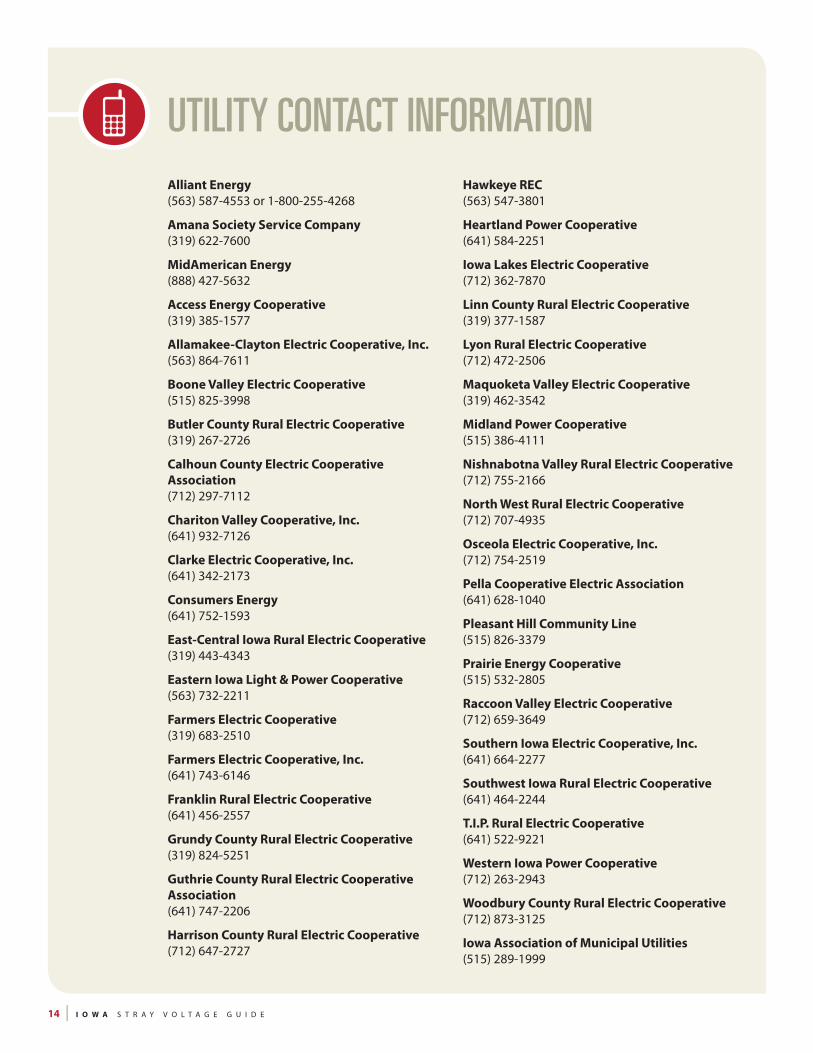
UTILITY CONTACT INFORMATIONAlliant Energy (563) 587-4553 or 1-800-255-4268
Amana Society Service Company (319) 622-7600
MidAmerican Energy (888) 427-5632
Access Energy Cooperative (319) 385-1577
Allamakee-Clayton Electric Cooperative, Inc. (563) 864-7611
Boone Valley Electric Cooperative (515) 825-3998
Butler County Rural Electric Cooperative (319) 267-2726
Calhoun County Electric CooperativeAssociation (712) 297-7112
Chariton Valley Cooperative, Inc. (641) 932-7126
Clarke Electric Cooperative, Inc. (641) 342-2173
Consumers Energy (641) 752-1593
East-Central Iowa Rural Electric Cooperative (319) 443-4343
Eastern Iowa Light & Power Cooperative (563) 732-2211
Farmers Electric Cooperative (319) 683-2510
Farmers Electric Cooperative, Inc. (641) 743-6146
Franklin Rural Electric Cooperative (641) 456-2557
Grundy County Rural Electric Cooperative (319) 824-5251
Guthrie County Rural Electric Cooperative Association (641) 747-2206
Harrison County Rural Electric Cooperative (712) 647-2727
Hawkeye REC (563) 547-3801
Heartland Power Cooperative (641) 584-2251
Iowa Lakes Electric Cooperative (712) 362-7870
Linn County Rural Electric Cooperative (319) 377-1587
Lyon Rural Electric Cooperative (712) 472-2506
Maquoketa Valley Electric Cooperative (319) 462-3542
Midland Power Cooperative (515) 386-4111
Nishnabotna Valley Rural Electric Cooperative (712) 755-2166
North West Rural Electric Cooperative (712) 707-4935
Osceola Electric Cooperative, Inc. (712) 754-2519
Pella Cooperative Electric Association (641) 628-1040
Pleasant Hill Community Line (515) 826-3379
Prairie Energy Cooperative (515) 532-2805
Raccoon Valley Electric Cooperative (712) 659-3649
Southern Iowa Electric Cooperative, Inc. (641) 664-2277
Southwest Iowa Rural Electric Cooperative (641) 464-2244
T.I.P. Rural Electric Cooperative (641) 522-9221
Western Iowa Power Cooperative (712) 263-2943
Woodbury County Rural Electric Cooperative (712) 873-3125
Iowa Association of Municipal Utilities (515) 289-1999
I O W A S T R A Y V O L T A G E G U I D E | 15
The following are examples of biosecurity practices one should strongly consider taking when working on a livestock farm. This list is not exclusive and therefore it is always important when scheduling the initial appointment to ask the farm owner or manager what biosecurity guidelines you should follow.
Suggestions for Farm Visitors:
Do not visit a livestock farm if you have been out of the continental U.S. in the past two weeks.
Enter the farm through the designated entrance area.
Park in the designated location for vehicles entering the farm. Do not park near the animal housing areas. Do not drive through the animal housing units.
Sign-in to the visitor log (name and date).
Declare to the farm owner/manager if you have been on another farm prior to visiting his/her facility.
Wear only clean or disposable clothing and boots. The farm owner/manager may provide disposable coveralls and plastic boots for visitors.
Use provided footbaths or disinfectant containers at the entrance to each animal housing area on the farm (when available). Always clean your boots when moving between animal housing units.
Do not have unnecessary direct animal, feed or water contact. Consider appropriate animal viewing locations that minimize risk of disease transmission.
Any equipment coming onto the farm should be cleaned and disinfected before it enters the property.
Sources: Biosecurity on Dairy Farms, University of Minnesota, College of Veterinary Medicine, Biosecurity, National Milk Producers Federation
INFORMATION ABOUT BIOSECURITY PROTOCOLS Other Biosecurity Resources:
All species:
www.biosecuritycenter.org/
www.farmandranchbiosecurity.com/
www.cfsph.iastate.edu/
Swine:
www.pork.org/filelibrary/Biosecurity/BiosecurityBook.pdf
www.pork.org/Resources/102/SecurityandBiosecurity.aspx
www.pork.org/Resources/3585/biosecurityonthefarm.aspx
www.pork.org/Research/4316/PEDVResources.aspx
Dairy:
www.aphis.usda.gov/animal_health/nahms/dairy/downloads/bamn/BAMN01_BiosecurityDairies.pdf
www.wvdl.wisc.edu/wp-content/uploads/2014/06/WVDL-biosecurity-for-dairy-farms.pdf
www.farmandranchbiosecurity.com/Dairy_Herds_Insert.pdf
Cattle:
www.ianrpubs.unl.edu/epublic/pages/publicationD.jsp?publicationId=433
www.iabeef.org/CMDocs/IowaBC/BiosecurityBasicsforCattleProducers.pdf
www.aphis.usda.gov/animal_health/nahms/beefcowcalf/downloads/beef0708/Beef0708_is_Biosecurity.pdf
Poultry:
www.cfsph.iastate.edu/Animal_Response/English/pdf/Prevention%20Practices%20Poultry.pdf
16 | I O W A S T R A Y V O L T A G E G U I D E
TESTING PROCEDURES Description of Phase I and Phase II Testing Procedures
3 If not completed as a part of Phase I.
Phase I Protocol
This is an initial screening for stray voltage at a farm done by conducting a “24-hour” test. It is used to determine stray voltage levels at animal contact locations. It is also used to assess the basic characteristics of the farm’s electrical system and the utility distribution system in the vicinity of the farm. A Phase I investigation would include the following:
Spot voltage checks are done at a representative number of animal contact locations to identify where animals may be exposed to voltage. Spot checks also identify the areas with higher voltage readings and where extended time animal contact voltage recording should be done. Voltage measurements are monitored with a recording voltage meter for a minimum of at least two milkings or approximately 24 hours. A nominal 500-Ohm resistor is used for extended animal contact monitoring in order to accurately measure the voltage livestock may feel. The recorder is also monitoring voltage levels on the utility electrical system at the transformer and the farm electrical system at a livestock building on the farm.
Detailed reports, data and explanations.
Providing a copy of the Proper Farm Wiring Summary. (See page 8)
Phase II Protocol
A comprehensive test strategy designed by the Wisconsin PSC and used to determine all sources of animal contact voltage both from on-farm and off-farm sources. There are five specific tests: (1) the load box test, (2) the secondary neutral voltage drop test, (3) the signature test, (4) the primary profile test, and (5) the “24-hour” test.3 These tests or other tests may be performed as necessary to give a complete account of the electrical activity on the farm.
Load Box Test (LB test)
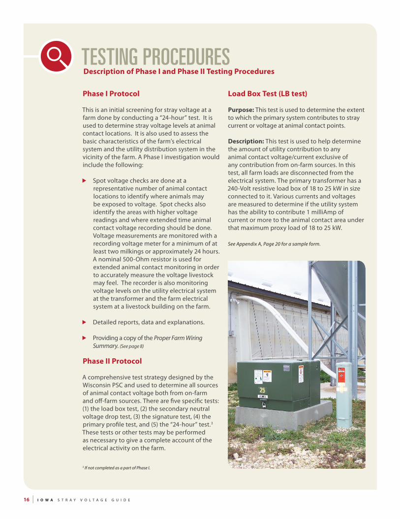
Purpose: This test is used to determine the extent to which the primary system contributes to stray current or voltage at animal contact points.
Description: This test is used to help determine the amount of utility contribution to any animal contact voltage/current exclusive of any contribution from on-farm sources. In this test, all farm loads are disconnected from the electrical system. The primary transformer has a 240-Volt resistive load box of 18 to 25 kW in size connected to it. Various currents and voltages are measured to determine if the utility system has the ability to contribute 1 milliAmp of current or more to the animal contact area under that maximum proxy load of 18 to 25 kW.
See Appendix A, Page 20 for a sample form.

I O W A S T R A Y V O L T A G E G U I D E | 17
This is a sample illustration of the test.
Secondary Neutral Voltage Drop Test
RemoteReference
Rod
Measure neutral currentoverhead or in panel
Centralyard pole
Vs*
Vps*
Hairdryer Repeat for
eachadditionalbuilding
Barn
Vp, Vs, Vps and Vc are alsorecorded in the Vc building
Either the transformer ground (the supplemental secondary ground
when isolated) or the centerdistribution point (cdp) can be used
depending on the evaluation being made.
Vp*
3.03
3.42
0.32
12A
Optional
Measured voltage drop (Vps*) iscompared to calculated
voltage drop
Secondary Neutral Voltage Drop Test (SNVD test)
Purpose: This test is used to determine the impact of each secondary service on the neutral-to-earth (NEV) and animal contact voltages on the dairy under controlled conditions.
Description: A test that looks at each farm electrical service to determine its possible contribution to animal contact voltage. For this test, one service at a time is energized and only one proxy load is powered. This load is usually a hair dryer or paint peeler having a uniform current draw at 120 V rms AC in excess of 10 Amps. Measurements are made of the physical length of the neutral from the main distribution panel to the sub-panel or load point being tested. The exact type of wire used for that neutral is noted
so that its resistance per hundred feet can be ascertained. A calculation is made of the product of the distance of the neutral (in hundreds of feet) and the resistance per hundred feet resulting in the total resistance of the neutral conductor. A measurement is made of the proxy load current and, using Ohm’s Law, a calculation is made of the expected voltage drop on the neutral wire at full load. The voltage drop from the source point to the load point is then measured and compared to the calculated value. If they differ significantly, this may indicate some unexpected resistance in the neutral circuit. The contribution to the animal contact voltage of this source is also measured and if it is significant, the condition is noted for possible mitigation.
See Appendix A, Page 22 for a sample form.
18 | I O W A S T R A Y V O L T A G E G U I D E
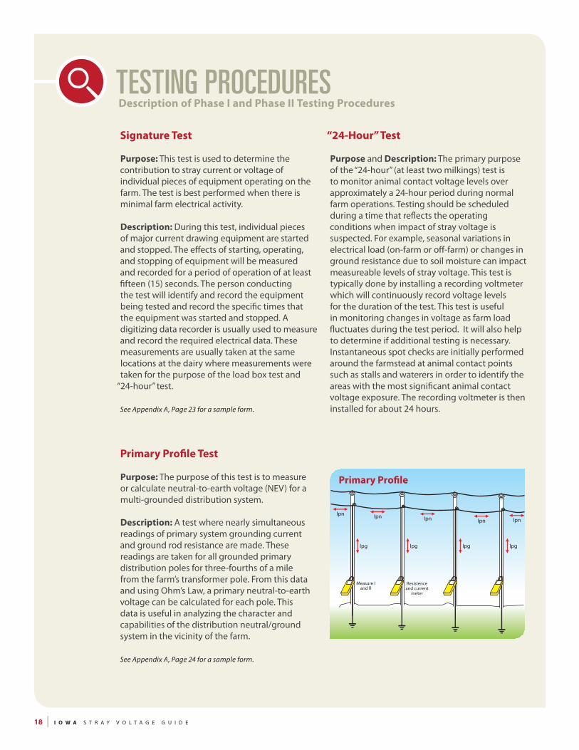
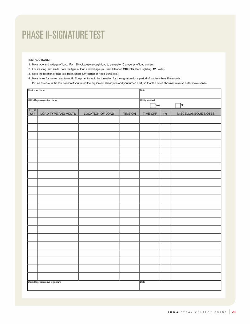
Signature Test
Purpose: This test is used to determine the contribution to stray current or voltage of individual pieces of equipment operating on the farm. The test is best performed when there is minimal farm electrical activity.
Description: During this test, individual pieces of major current drawing equipment are started and stopped. The effects of starting, operating, and stopping of equipment will be measured and recorded for a period of operation of at least fifteen (15) seconds. The person conducting the test will identify and record the equipment being tested and record the specific times that the equipment was started and stopped. A digitizing data recorder is usually used to measure and record the required electrical data. These measurements are usually taken at the same locations at the dairy where measurements were taken for the purpose of the load box test and
“24-hour” test.
See Appendix A, Page 23 for a sample form.
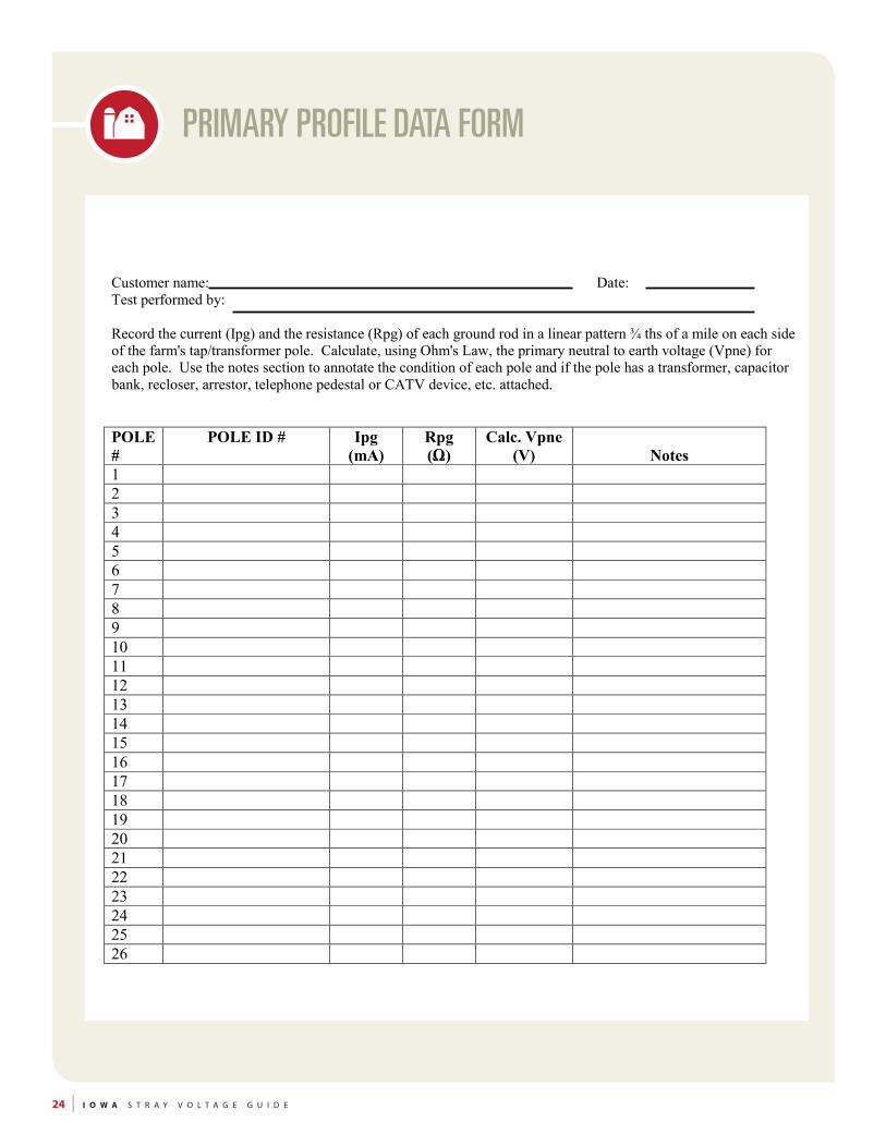
Primary Profile Test
Purpose: The purpose of this test is to measure or calculate neutral-to-earth voltage (NEV) for a multi-grounded distribution system.
Description: A test where nearly simultaneous readings of primary system grounding current and ground rod resistance are made. These readings are taken for all grounded primary distribution poles for three-fourths of a mile from the farm’s transformer pole. From this data and using Ohm’s Law, a primary neutral-to-earth voltage can be calculated for each pole. This data is useful in analyzing the character and capabilities of the distribution neutral/ground system in the vicinity of the farm.
See Appendix A, Page 24 for a sample form.
“24-Hour” Test
Purpose and Description: The primary purpose of the “24-hour” (at least two milkings) test is to monitor animal contact voltage levels over approximately a 24-hour period during normal farm operations. Testing should be scheduled during a time that reflects the operating conditions when impact of stray voltage is suspected. For example, seasonal variations in electrical load (on-farm or off-farm) or changes in ground resistance due to soil moisture can impact measureable levels of stray voltage. This test is typically done by installing a recording voltmeter which will continuously record voltage levels for the duration of the test. This test is useful in monitoring changes in voltage as farm load fluctuates during the test period. It will also help to determine if additional testing is necessary. Instantaneous spot checks are initially performed around the farmstead at animal contact points such as stalls and waterers in order to identify the areas with the most significant animal contact voltage exposure. The recording voltmeter is then installed for about 24 hours.
TESTING PROCEDURES Description of Phase I and Phase II Testing Procedures
Ipn Ipn Ipn IpnIpn
Ipg Ipg Ipg Ipg
Measure Iand R
Resistenceand current
meter
Primary Prole

I O W A S T R A Y V O L T A G E G U I D E | 19
Sample Forms
The following are sample forms for performing the various tests for stray voltage. These forms were developed from materials from the Wisconsin Public Service Commission. For details on completing the forms visit the following website:
psc.wi.gov/utilityinfo/electric/strayvoltage.htm
APPENDIX A

20 | I O W A S T R A Y V O L T A G E G U I D E
Date Customer Name Customer Premise No.
XXXXXXX XXXXXXXX XXXXXXX
FARM OFF FARM ON
NO LOAD 1/2 LOAD (Low) FULL LOAD (hi) LOAD BOX OFF
CALCULATIONS (Farm Off) SUMMARY
Rt = Vp hi - Vp Low = ______________________________________________ = ________________________________________________ohmsIp hi - Ip Low
Rp = Vp hi - Vp Low = ______________________________________________ = ________________________________________________ohmsIpn hi - Ipn Low
Rf = Vs hi - Vs Low = ______________________________________________ = ________________________________________________ohmsIsn hi - Isn Low
K = Vc hi = ______________________________________________ = ________________________________________________%Vs hi
CR = Ipn hi - Ipn Low = ______________________________________________ = ________________________________________________%Ip hi - Ip Low
Primary Phase Current may be calculated using the measured secondary current of the load box and the known transformer ratio (ex. for a 240 volt secondary load box you measure 100 amps, with a 30:1 transformer ratio, the phase current at 7,200 volts would be 100 amps / 30 = 3.3 amps)
Page 1 of 2
NEUTRAL ISOLATOR INSTALLED: Yes No
TIME
Ip
Ipn
Isn
Isn net
Vp
Vs
Vps
Vc
FULL LOAD
Meas Calc
Notes:
PRIMARY NEUTRAL VOLTAGE DROP-LOAD BOX
I O W A S T R A Y V O L T A G E G U I D E | 21
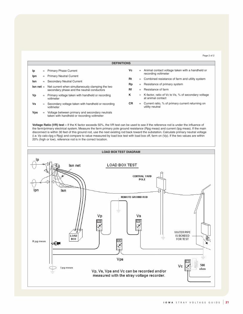
Vc = Animal contact voltage taken with a handheld or recording voltmeter
Rt = Combined resistance of farm and utility system
Rp = Resistance of primary system
Rf = Resistance of farm
K = K-factor, ratio of Vc to Vs, % of secondary voltage at animal contact
CR = Current ratio, % of primary current returning on utility neutral
DEFINITIONS
Ip = Primary Phase Current
Ipn = Primary Neutral Current
Isn = Secondary Neutral Current
Isn net = Net current when simultaneously clamping the two secondary phase and the neutral conductors
Vp = Primary voltage taken with handheld or recording voltmeter
Vs = Secondary voltage taken with handheld or recording voltmeter
Vps = Voltage between primary and secondary neutrals taken with handheld or recording voltmeter
Page 2 of 2
LOAD BOX TEST DIAGRAM
Voltage Ratio (VR) test – If the K factor exceeds 50%, the VR test can be used to see if the reference rod is under the influence of the farm/primary electrical system. Measure the farm primary pole ground resistance (Rpg meas) and current (Ipg meas). If the main disconnect is within 30 feet of this ground rod, use the next existing rod back toward the substation. Calculate primary neutral voltage (i.e. Vp calc=Ipg x Rpg) and compare to value measured by load box test with load box off, farm on (Vp). If the two values are within 20% (high or low), reference rod is in the correct location.

22 | I O W A S T R A Y V O L T A G E G U I D E
Customer Name: Isolated? Y N:peR ytilitU:etaD
AW
G
Ft
OFF ON OFF ON OFF ON
A
V
V
V
V
Vp V
Vs V
Vps V
Vc V
Com
men
ts:
Size Al: Cu: Size Al: Cu:* Indicates a building other than the Vc building. 14 0.420 0.260 3 0.034 0.020** Center Distribution Point Ground (cdp) 12 0.260 0.160 2 0.027 0.016 Supplementary Secondary Ground (ssg) 10 0.170 0.100 1 0.021 0.013 Transformer Ground (xfmr) 8 0.110 0.064 1/0 0.017 0.010
6 0.067 0.041 2/0 0.013 0.0084 0.042 0.026 3/0 0.011 0.006
4/0 0.008 0.005
Either the transformer ground (ssg when isolated) or the center distribution point (cdp) can be used depending on the evaluation being made. If using tranformer ground, Vp=Vp* when not isolated.
Vs*(Equipment ground to ref rod)
Vp* ref. rod toNOTE - circle onecdp / xmfr / ssg **
Rec
orde
r in
build
ing
with
Vc
B.Wire Length/100
C.Ohms/100ft
D.Total Ohms (BxC)
A.Wire size
Resistance Chart (Ohms per 100 feet)
E.Measuredneutral currentF.CalculatedVoltage Drop (DxE)Vps* -measured VD( Equipment ground to cdp / xfmr / ssg **)
Hairdryer (120V load) time
( All other farm loads off, and use only one load per site. Notes and exceptions recorded at bottom)
Location
PHASE II-SECONDARY NEUTRAL VOLTAGE DROP TEST
I O W A S T R A Y V O L T A G E G U I D E | 23
PHASE II SIGNATURE TEST
INSTRUCTIONS:
1. Note type and voltage of load. For 120 volts, use enough load to generate 10 amperes of load current.
2. For existing farm loads, note the type of load and voltage (ex. Barn Cleaner, 240 volts, Barn Lighting, 120 volts).
3. Note the location of load (ex. Barn, Shed, NW corner of Feed Bunk, etc.).
4. Note times for turn-on and turn-off. Equipment should be turned on for the signature for a period of not less than 10 seconds.
Put an asterisk in the last column if you found the equipment already on and you turned it off, so that the times shown in reverse order make sense.
Customer Name Date
Utility Representative Name Utility Isolated
Yes No
TEST NO.
LOAD TYPE AND VOLTS
LOCATION OF LOAD
TIME ON
TIME OFF
(*)
MISCELLANEOUS NOTES
Utility Representative Signature Date
PHASE II-SIGNATURE TEST
24 | I O W A S T R A Y V O L T A G E G U I D E
Customer name: Date: Test performed by: Record the current (Ipg) and the resistance (Rpg) of each ground rod in a linear pattern ¾ ths of a mile on each side of the farm's tap/transformer pole. Calculate, using Ohm's Law, the primary neutral to earth voltage (Vpne) for each pole. Use the notes section to annotate the condition of each pole and if the pole has a transformer, capacitor bank, recloser, arrestor, telephone pedestal or CATV device, etc. attached. POLE #
POLE ID # Ipg (mA)
Rpg (Ω)
Calc. Vpne (V)
Notes
1 2 3 4 5 6 7 8 9 10 11 12 13 14 15 16 17 18 19 20 21 22 23 24 25 26
PRIMARY PROFILE DATA FORM

I O W A S T R A Y V O L T A G E G U I D E | 25
Examples of items to include:
1. Graph of voltages recorded during the monitoring period.
2. Highest animal contact steady-state voltage measured during testing and the location of that measurement.
3. Reference to the standard used by the utility for decision making regarding more testing to determine voltage sources.
4. If necessary, a description of any utility changes that were made during testing or will be made after testing.
5. Provide farm wiring recommendations or reference a farm wiring guide or checklist.
Sample Letter:
Dear Insert farmer name,
This report summarizes the stray voltage analysis that your utility conducted on your farm (INSERT DATE). Thanks for your cooperation during this time.
Following is a graph from the stray voltage recorder showing voltage levels measured. The green line shows animal contact (stall to floor at the north parlor entry door) voltage. The red line shows primary neutral at the transformer to remote ground rod levels and the black line shows the parlor and milk house service panel grounding bar (secondary neutral) to a remote ground rod.
The highest cow contact steady state voltage level measured in the parlor was 0.25 volt. Cow contact measurements were taken with a nominal 500-Ohm resistor.
Stray voltage can come from on-farm or off-farm sources. The utility uses a conservative, preventative action level of 1.0 volt steady state voltage for animal contact areas to prevent cow avoidance behavior. The levels of steady state voltage measured on your farm do not exceed this level. The utility will take action if 0.5 volt or greater is coming from off-farm sources and the farmer is encouraged to take action if the on-farm contribution is 0.5 volt or greater. For your farm, the off-farm contribution was measured at 0.25 volt, which is under the 0.5 volt level where your utility will take action to reduce its contribution to animal contact areas based on a 20 kW load test. In order to keep stray voltage levels low, refer to the enclosed farm wiring checklist. Always make wiring improvements in accordance with the National Electrical Code.
If you have any questions on this report, call me at xxx-xxx-xxxx.
Sincerely,
APPENDIX BModel Report for Utilities to Use with Farmers

26 | I O W A S T R A Y V O L T A G E G U I D E
The following is not intended to be an exhaustive list of resources but at least a beginning point.
United States Department of Agriculture Handbook (USDA Handbook) titled “Effects of Electrical Voltage/Current on Farm Animals: How to Detect and Remedy Problems” issued December 1991 naldc.nal.usda.gov/download/CAT92970513/PDF
Public Service Commission of Wisconsin psc.wi.gov/utilityinfo/electric/strayvoltage.htm
Midwest Rural Energy Council (MREC) The Midwest Rural Energy Council (MREC) (www.mrec.org/) has developed a number of publications on rural energy issues. The following brochures are from 8 to 20 pages long and provide detailed coverage of the subject matter. For orders of 500 or more copies of one brochure, the brochures may be special printed with your logo attached. If you would like a single copy or would like to review these MREC publications, they are available for download by clicking the following links.
Wiring Handbook for Rural Facilities www-mwps.sws.iastate.edu/catalog/construction/wiring-handbook-rural-facilities
Equipotential Planes for Stray Voltage Reduction: Installation Guidelines fyi.uwex.edu/mrec/files/2011/02/2006-MREC-Equipotential-Planes.pdf
Planning Electrical Systems for Dairy Expansions fyi.uwex.edu/mrec/files/2011/02/pes2.pdf
Farming Safely and Efficiently with Electricity fyi.uwex.edu/mrec/files/2011/02/farmsafe.pdf
Stray Voltage Detection: A Self-Help Guide fyi.uwex.edu/mrec/files/2011/02/svd.pdf
Power Quality and Computers on the Farm fyi.uwex.edu/mrec/files/2011/02/pq.pdf
Installation and Operation of Fencers, Cow Trainers and Crowd Gates fyi.uwex.edu/mrec/files/2011/02/ElectricFencers_MREC_05.pdf
Wind Turbines and Farm Stray Voltage fyi.uwex.edu/mrec/files/2014/03/WindTurbinesStrayVoltage-pages.pdf
MREC Informational Sheets These short, one page informational sheets give a brief overview of a specific subject. These informational sheets can be downloaded to get you up-to-speed quickly on some frequently asked questions. The MREC encourages you to distribute these documents in electronic or printed format to anyone with a question.
Installation and Maintenance of Cow Trainers (landscape version) fyi.uwex.edu/mrec/files/2011/04/Trainer-TriFold-16july05.pdf
Installation and Maintenance of Cow Trainers (portrait version) fyi.uwex.edu/mrec/files/2011/04/trainer-portrait-16july05.pdf
APPENDIX CList of Reference Materials for Utilities and Farmers

I O W A S T R A Y V O L T A G E G U I D E | 27
Installing Electrified Crowd Gates (landscape version) fyi.uwex.edu/mrec/files/2011/04/crowd-gate-TriFold-16july05.pdf
Installing Electrified Crowd Gates (portrait version) fyi.uwex.edu/mrec/files/2011/04/crowd-gate-portrait-16july05.pdf
Stray Voltage fyi.uwex.edu/mrec/files/2011/04/StrayVoltage_InformationalPage_05.pdf
High Frequency Noise fyi.uwex.edu/mrec/files/2011/04/HighFrequencyNoise_InformationalPage_05.pdf
Earth Currents fyi.uwex.edu/mrec/files/2011/04/EarthCurrents_InformationalPage_05.pdf
Electrical Pollution fyi.uwex.edu/mrec/files/2011/04/ElectricalPollution_InformationalPage_05.pdf
Electric and Magnetic Fields (EMF) fyi.uwex.edu/mrec/files/2011/04/Emf_2008.pdf
Wiring Handbook for Rural Facilities www-mwps.sws.iastate.edu/catalog/construction/wiring-handbook-rural-facilities Note: The above handbook can be purchased for a nominal fee from the above website.
National Electrical Safety Code standards.ieee.org/findstds/standard/C2-2012.html Generally this is the code that applies on the utility side of the meter. The above website has the applicable code sections available for purchase.
National Electrical Code www.nfpa.org/codes-and-standards/document-information-pages?mode=code&code=70 Generally this is the code that applies on the customer side of the meter. The above website has the applicable code sections available for purchase.
The Iowa Utilities Board, a division of the Iowa Department of Commerce, regulates Iowa’s utility companies. This regulatory authority encompasses certain power quality issues, such as stray voltage. If you have an issue that cannot be resolved by the parties, you may file a complaint with the Utilities Board; however, the Board does not have the authority to award damages in these instances. The following link on their website will give you more information about filing with the Board. www.state.ia.us/government/com/util/complaints/index.html
The following organizations developed this guide.
JU
LY
20
14
Iowa Association of Electric Cooperatives
For questions about stray voltage contact your electric utility. See page 14 for a list of utility contacts.