JUKI CORPORATION - raichert.com
68
JUKI CORPORATION R
Transcript of JUKI CORPORATION - raichert.com

JUKI CORPORATION
R

【【【【CONTENTS】】】】
Ⅰ)Ⅰ)Ⅰ)Ⅰ) Classification of the industrial sewing machine ……………………………………………………………………………………………… 1 Ⅱ)Ⅱ)Ⅱ)Ⅱ) Kind of the stitch …………………………………………………………………………………………………………………………………………………………………………………………………………………………………………………………………………………… 2
1. Classification of stitch (stitch type) based on JIS
2. Stitch type and the feature
1) Chainstitch 2) Hand stitch machine 3) Lockstitch
4) Double chainstitch 5) Over-edge chain stitch 6) Covering chainstitch
Ⅲ)Ⅲ)Ⅲ)Ⅲ) Six major elements of sewing …………………………………………………………………………………………………………………………………………………………………………………… 14141414
1. Needle bar …………………………………………………………………………………… 14 2. Hook …………………………………………………………………………………………… 22 3. Thread take-up lever ……………………………………………………………………… 33 4. Feed dog ……………………………………………………………………………………… 35 5. Presser foot …………………………………………………………………………………… 40 6. Thread tension ……………………………………………………………………………… 43
Ⅳ)Ⅳ)Ⅳ)Ⅳ) Defects of sewing that occur in sewing process and definition of terms ……………………………………………………………………………………………………………………………………………………………………………………………………………………………… 50
Ⅴ)Ⅴ)Ⅴ)Ⅴ) Adjustment procedure ……………………………………………………………………………………………………………………………………………………………………………………………………………………………… 53 ⅥⅥⅥⅥ) Knowledge of the sewing thread ……………………………………………………………………………………………………………………………………………………………… 56 Reference data …………………………………………………………………………………………………………………………………………………………………………………………………………………………………………………………………………………………………………………… 61

1
Industrial sewing m
achine
Ⅰ)Ⅰ)Ⅰ)Ⅰ) Classification of the industrial sewing machine
・・・・ Mark (class) of classification of the stitch type based on JIS L0120 : ( ) 6 classes ・・・・ Mark of large classification (stitch style) of classification of the industrial sewing machine based on JIS
B9070 : 《 》 8 classes ⇒medium classification (application), small classification (shape of machine
bed)
Hand stitching
(200)
《S》: Special sewing
General hand stitching .. Hand stitching sewing machine
Special hand stitching .. Wrapped-around button sewing
machine
Lockstitch
(300)
《L》
General lockstitch .. 1-needle, and 2-needle sewing machines
Blind stitching .. Blind stitching machine
Special single chainstitch .. Chainstitch button sewing machine Chainstitch
Chainstitch
(100)
《C》
General chainstitch .. Blind stitching and basting
Chainstitch blind stitching .. Chainstitch blind stitching machine
Special lockstitch .. Bottonholing, bartacking and button sewing machines
Double chainstitch
(400)
《D》
General double chainstitch .. 1-needle to multi-needle
sewing machine
Zigzag stitch .. Zigzag sewing machine
Special double chainstitch .. Eyelet buttonholing machine
.. Safety stitch machine
(interlock machine)
Over-edge chainstitch
(500)
《E》
Covering chainstitch
(600)
《F》
Welding 《W》
Bonding
Various overlock sewing machines
The work to be processed is welded or bonded as a
substitute for seams.
2-needle, 3-needle and 4-needle sewing machines
Compound stitch
《M》
Zigzag stitching .. Zigzag stitching machine, and embroidering sewing machines

2
Ⅱ)Ⅱ)Ⅱ)Ⅱ) Kind of the stitch 1. Classification of stitch (stitch type) based on JIS L0120 <Table Ⅱ-1>
Class Stitch type Number of subdivided classes The stitch is sorted by 6 classes 100 Chainstitch 7 and each class is subdivided. 200 Hand stitch 13 Number of subdivided classes is 88 300 Lockstitch 27 in total. 400 Double chainstitch 17 500 Over-edge chainstitch 15 600 Covering chainstitch 9
2. Stitch type and the feature
1) Chainstitch ① Example of stitch formation
② Feature
A piece of thread is interlaced like a chain under the cloth and the stitches are formed as knitted.
The constructive feature is that the stitches are untied one after another when the interlacement at the end
of sewing comes off.
③ Application
Basting (ML-111), button sewing (AMB-189N), (MB-377), chainstitch buttonholing (MBH-180S), blindstitch
and closing of bag opening ④ Stitch formation
a : Needle thread slacks at the position where needle
slightly goes up from its lowest position, and
looper catches the needle thread which has
become like a loop.
Also, the needle enters the circle of needle thread
which is widened by the looper.
<Fig. ⅡⅡⅡⅡ-1> <Fig. ⅡⅡⅡⅡ-2>
JIS mark 101 ... Chainstitch JIS mark 103 ... Blindstitch
<Fig. ⅡⅡⅡⅡ-3>
Needle
Looper

3
d : Cloth feed is finished and a stitch is formed.
Needle penetrates the cloth to continue to next
stitch, a : .
c : Looper continues rotating and pulls in the thread
in the center of the looper and thread take-up
lever tightens the thread which the looper
removed before.
b : Needle comes off the cloth and the cloth is fed.
Looper rotates and removes the thread which the
looper caught before while pulling in the needle
thread. Needle bar continues going up and needle
thread take-up lever lifts the thread.
<Fig. ⅡⅡⅡⅡ4>
<Fig. ⅡⅡⅡⅡ-6>
<Fig. ⅡⅡⅡⅡ-5>

4
2) Hand stitch machine ① Example of stitch formation JIS mark 209 ... Hand stitch
② Feature
Same stitch as that of hand stitch is formed by a piece of thread. Thread is drwan in every stitch or every
other stitch and the length of stitching is limited. Since friction is given at the same position of the sewing
thread many times, the thread is untwined during sewing resulting in thread breakage unless the thread is a
high-durable one. Even when the sewing is made, the stitch looks broken.
Therefore, the thread that can be used is limited.
③ Application
Decorative stitch of suits or the like (FLS-350N), kimono (Japanese national dress) (FLS-351N)
Button sewing of coats, suits, etc. (FBS-340N-1) ④ Stitch formation
b : Needle penetrates the cloth and is
delivered to the lower needle bar.
Thr right-hand looper returns to its
home place.
a : Needle is fixed to upper needle bar, and
left-hand and right-hand loopers draw and
retain the thread. Cloth is fed and the
needle comes down.
<Fig. ⅡⅡⅡⅡ-7>
<Fig. ⅡⅡⅡⅡ-8> <Fig. ⅡⅡⅡⅡ-9>
Left
Right
Left
Right

5
f : Needle penetrates the cloth, and is delivered to
the upper needle bar and goes up. Thread is
wiped out by the lower looper. Next, the above
left-hand and right-hand loopers catch the
thread to continue to a : .
d : Lower looper draws out thread which enters
under the cloth one stitch before from the
above left-hand looper. Simultaneously the
cloth is fed.
e : Needle goes up and penetrates the cloth.
Lower looper further pulls in the thread
downward.
c : Lower looper catches the thread loop at
the position where the lower needle bar
slightly goes up from its lowest position.
<Fig. ⅡⅡⅡⅡ-10> <Fig. ⅡⅡⅡⅡ-11>
<Fig. ⅡⅡⅡⅡ-12> <Fig. ⅡⅡⅡⅡ-13>
Lower looper
Left Left
Lower
Left
Right
Lower
Lower
Lower

6
3) Lockstitch ① Example of stitch formation JIS mark 301 ... 1-needle lockstitch JIS mark 304 ... 1-needle lockstitch zigzag stitch
② Feature
Two threads of upper thread (needle thread) and lower thread (bobbin thread) are used. Every stitch upper
thread and lower thread interlace each other and the stitches on right and wrong sides are the same. This
stitch is widely used since it is not easily frayed and securely joins plural pieces of cloth.
It is necessary to replace the bobbin thread since stitch formation is obtained by rotation of the needle thread
around the bobbin case. ③ Application
General sewing (DDL-5550N, DDL-5700-7, DLU-5490N-7, DLN-5410N-7), Shirring (DLU-5494N-7),
2-needle lockstitch (LH-3128-7), Zigzag stitch (LZ-2288N-7), Plain stitch, Decorative stitch,
Bartacking (LK-1900), Lockstitch buttonholing (LBH-790RS-1), Button sewing (LK-1903/BR25),
Pockect sewing (APW-196) and Pattern sewing (AMS-210D)
④ Stitch formation ④-1 Horizontal full-rotary hook
b : Upper thread which is pulled in by the blade point
of outer hook is separated at the inner hook
thread separating portion so that the upper thread
on the needle side is separated to the rear side of
inner hook and the upper thread on cloth side is
separated to the right side of inner hook.
a : Upper thread slacks at the position where the
needle slightly goes up from its lowest
position, and blade point of outer hook
catches the loop-shaped upper thread and
pulls in the upper thread.
<Fig. ⅡⅡⅡⅡ-14> <Fig. ⅡⅡⅡⅡ-15>
<Fig. ⅡⅡⅡⅡ-16>
<Fig. ⅡⅡⅡⅡ-17>
Thread on cloth side
Inner hook thread separating portion
Thread on needle side

7
(
e : Stitch is formed when the upper thread lifts the
lower thread and cloth is fed at the end. Next,
needle comes down and penetrates cloth to
continue to a : .
d : Immediately after upper thread has
rotated around inner hook, thread
take-up lever lifts upper thread and the
upper thread is interlaced with the lower
c : Outer hook rotates, while pulling in upper thread,
around the periphery of bobbin case containing
lower thread set in inner hook. Thread take-up lever
supplies upper thread which is necessary to rotate
around inner hook. (Suppose that inner hook is a
human being, and it looks like doing rope-skipping.)
<Fig. ⅡⅡⅡⅡ-18> <Fig. ⅡⅡⅡⅡ-19>
<Fig. ⅡⅡⅡⅡ-20>
Thread on needle side (rear side of inner hook)
Lower thread
Thread on cloth side

8
④-2 Semi-rotary hook
d : Stitch is formed when the upper thread
lifts the lower thread and cloth is fed at the
end. To be continued to a : .
c : After 1/2 rotation of the hook, upper
thread is lifted by thread take-up lever
and is interlaced with lower thread.
b : Upper thread rotates around the periphery
of bobbin case by rotation of the hook. a : Blade point of semi-rotary hook catches
loop-shaped upper thread.
<Fig. ⅡⅡⅡⅡ-22>
<Fig. ⅡⅡⅡⅡ-21>
Needle
Lower thread
Upper thread
Cloth Needle
Upper thread
Cloth
Lower thread
<Fig. ⅡⅡⅡⅡ-23>
Needle
Lower thread
Upper thread
Cloth
<Fig. ⅡⅡⅡⅡ-24>
Needle
Lower thread
Upper thread
Cloth

9
4) Double chainstitch ① Example of stitch formation
JIS mark 401 ... 1-needle double chainstich JIS mark 406 ... 2-needle double chainstitch
② Feature
Upper thread (needle thread) and lower thread (looper thread) are interlaced with each other like a chain
under cloth, and the stitches look like knitted.
The stitches look the same as those of lockstitch when observing from the surface of cloth. Sewing can be
performed continuously for a long time since lower thread as well as upper thread can be supplied
continuously. Stitches are full of elasticity, and widely used for the elastic cloth and places to which shock is
applied. Defect, when compared with the lockstitch, is that the stitch is easily frayed. ③ Application
General sewing (MH-481-5) Rubber tape attaching, Lace attaching to underwear, swim-suit, etc.
Eyelet buttonholing (MEB-2688), Side seam (MS-1190), Belt loop making (MFB-2600) ④ Stitch formation
b : Needle continues to go up and looper
thread comes off needle. Looper
advances in the state that it has
scooped needle thread.
a : Needle thread comes off looper and is
tightened. Then, looper scoops needle
thread at the position where needle slightly
goes up from its lowest position.
<Fig. ⅡⅡⅡⅡ-25> <Fig. ⅡⅡⅡⅡ-26>
<Fig. ⅡⅡⅡⅡ-27> <Fig. ⅡⅡⅡⅡ-28>

10
5) Over-edge chain stitch ① Example of stitch formation
JIS mark 504 ... 1-needle overlock JIS mark 506 ... 2-needle overlock
② Feature In many cases, three threads of upper thread (needle thread) and lower threads (upper looper thread and
lower looper thread) are interlaced with one another so as to hem material end, and the stitches look like
knitted.
This stitch belongs to the classification of chainstitch. The stitch itself can expand following the expansion of
cloth. Accordingly, this stitch is mostly used for the cloth which is largely expanded (knit or the like). ③ Application
Cloth which is largely expanded, blind over-edging, prevention of fray at material end (ASN-397/serging
machine)
Overlock sewing machine (MO-3904), 2-needle overlock machine (MO-3914), Cylinder-bed overlock sewing
machine (MOC-3914)
c : Cloth is fed when needle is in the highest
dead point and looper is in the most
advanced state, and the final tightening of
needle thread is performed.
d : Needle comes down and the needle tip
scoops looper thread. Looper performs elliptic
motion. Then, stitch formation is continued to
<Fig. ⅡⅡⅡⅡ-31> <Fig. ⅡⅡⅡⅡ-32>
ルーパーの楕円運動ルーパーの楕円運動ルーパーの楕円運動ルーパーの楕円運動
ルーパーが針糸をすくう
針先でルーパー糸をすくう
針
<Fig. ⅡⅡⅡⅡ-29> <Fig. ⅡⅡⅡⅡ-30>
Needle
Looper scoops needle thread.
Needle tip scoops looper thread.
Elliptic motion of looper

11
④ Stitch formation
上ルーパー糸
下ルーパー糸
針糸
抜ける
d : Needle tip scoops upper looper thread. c : Cloth is fed.
b : Upper looper thread comes off needle and
upper looper scoops lower looper thread. a : Lower looper scoops needle thread loop.
<Fig. ⅡⅡⅡⅡ-33> <Fig. ⅡⅡⅡⅡ-34>
<Fig. ⅡⅡⅡⅡ-35> <Fig. ⅡⅡⅡⅡ-36>
Upper looper thread
Needle thread
Lower looper thread
Comes off.

12
《Extra : Compound stitching》
Feature This stitch is favourable to the productivity since double chainstithing and over-edge chainstitching are
simultaneously performed (safety stitch).
The machine is called "Interlock machine". (MO-3916)
Application General runstitching, side joining of shirts, slacks, etc.
6) Covering chainstitch ① Example of stitch formation
JIS mark 605 ... 3-needle covering chainstitch JIS mark 602 ... 2-needle covering chainstitch
f : Needle thread which is before one stitch is
tightened at the lower dead point of needle.
Stitch formation is continued to a : .
e : Lower looper thread which is caught on upper
looper comes off. Then, needle thread which
is caught on lower looper comes off.
<Fig. ⅡⅡⅡⅡ-39> <Fig. ⅡⅡⅡⅡ-40>
<Fig. ⅡⅡⅡⅡ-37> <Fig. ⅡⅡⅡⅡ-38> Comes off
Comes off

13
② Feature There are two or more needle threads and decorative threads on both the right and wrong sides of cloth
(generally, upper decorative thread is attached to 2-needle or 3-needle double chainstitch). The stitch is full
of elasticity and looks nice. ③ Application
Hemming (MFC-7605/AH-1) Decorative stitch for lace attaching to underwear, swim-suits, etc. ④ Stitch formation
a : Lower looper scoops needle thread loop,
and simultaneously upper decorative
looper scoops upper decorative thread.
d : Needle thread comes off lower looper and needle
comes down in its lowest position. Lower looper and
upper decorative looper are in the most retracted
positions. Stitch formation is continued to a : .
b : Cloth is fed and only right-hand needle is
positioned in the outside of decorative thread.
Two left-hand needles come down and scoop
upper decorative thread.
c : Needles further come down and scoop
lower looper thread. And, two right-hand
needles enter in between the respective
needle threads as shown in the illustration.
<Fig. ⅡⅡⅡⅡ-43> <Fig. ⅡⅡⅡⅡ-44>
<Fig. ⅡⅡⅡⅡ-41> <Fig. ⅡⅡⅡⅡ-42>
Needle thread Looper scoops upper decorative thread.
Lower looper scoops needle thread.
Lower looper thread
Needles scoop upper decorative thread.
Needles scoop lower looper thread.
Needle thread comes off.

14
Ⅲ)Ⅲ)Ⅲ)Ⅲ) Six major elements of sewing The industrial sewing machine as well as machine tool is the productive goods. The machine has special
functions (the functions are largely seen in automatic machines) in addition to the sewing aiming efficiency
promotion and deskilling. Also, there are many kinds of the machine.
Basic function of the sewing machine is, however, to stitch using thread whatever the equipment may be.
Namely, the first purpose is to form stitches on the cloth and to secure satisfactory quality.
Stitch formation consists of the following six factors. These are called "Six major factors or mechanisms of
sewing". 1. Needle bar 2. Hook (looper for chainstitch) 3. Thread take-up lever 4. Feed 5. Presser foot 6. Thread tension
1. Needle bar
1) Function ① Needle bar makes needle up and down, and upper thread penetrate into the material
to be sewn. ② Needle bar makes hook or looper scoop the penetrated upper thread. ③ Needle bar scoops looper thread at the needle tip. (For chainstich)
2) Momentum (stroke) of needle bar
The momentum of needle bar is not one kind since the sewing machine sews cloths of various thicknesses.
There are three kinds (for heavy-weight, medium-weight and light-weight materials) of momentum for
1-needle lockstitch machine.
When the needle bar stroke is large, there are such merits as ① penetrating force is improved, ②
distance from throat plate to upper dead point of needle tip becomes larger and thick material is easily
entered, etc. Demerits are ① inertia force is increased and vibration or noise is likely to occur, ②
mechanical load is increased and it is not fit to high speed, ③ needle heat rises, etc.
Light-weight materials → small stroke Heavy-weight materials → large stroke
Example : DDL-5550 = 30.5 mm/DDL-5550H = 35 mm/DDL-5550A = 29 mm/LG-158 = 46.88 mm H type = for heavy-weight materials A type = for light-weight materials

15
3) Needle Needle is attached to the top of needle bar and is one of the most important parts to sew materials.
If needle is not good, it will be the cause of various troubles such as thread breakage, material breakage,
puckering (wrinkle by sewing), etc.
If there is any problem related to the sewing, it is general to check whether threading is proper, then to
check whether needle is defective.
Example of blunt needle tip <Normal> <Blunt needle tip>
① Symbol of dimension and name
<Fig. ⅢⅢⅢⅢ-1>
A : Shank diameter
B : Shoulder
diameter
E : Length of needle
D : Butt to eyelet
J : Length of eyelet
K : Width of eyelet
N : Length of shank
H : Length of scarf
Z : Detpth of groove
F : Length of point
Shape of scarf Standard type shape Boat-shaped type
<Photo. ⅢⅢⅢⅢ-1> <Photo. ⅢⅢⅢⅢ-2>

16
Conversion table of needle size of various countries <Table ⅢⅢⅢⅢ-1> Sizes Needle
trunk sizes Sizes Needle
trunk sizes ORGAN
(Japan) GERMANY UNION
(U.S.A.) ORGAN
(Japan) ORGAN
(Japan) GERMANY UNION
(U.S.A.) ORGAN
(Japan) 5 45 / 0.47 16 100 040 1.02
6 50 / 0.52 17 105 042 1.07
7 55 022 0.57 18 110 044 1.12
8 60 / 0.62 19 120 048 1.22
9 65 027 0.67 20 125 049 1.27
10 70 029 0.72 21 130 / 1.32
11 75 030 0.77 22 140 054 1.42
12 80 032 0.82 23 160 / 1.62
13 85 034 0.87 24 180 078 1.82
14 90 036 0.92 25 200 080 2.02
15 95 038 0.97 26 230 090 2.30
② Shank diameter : A = Mainly divided into the following three systems. For overlock system DC x 1, DC x 27 ... 2.02 mm
For lockstitch system DA x 1 ... 1.62 mm (#7 to #22)
DB x 1 ... 1.62 mm (#7 to #18)
... 1.90 mm (#19)
... 2.02 mm (#20 or more)
For special sewing machine system
such as straight buttonholing or the like DP x 5 ... 2.00 mm
* For the shank diameter to be used in overseas, refer to "Reference data 1" in the end of this volume. (P.61) ③ Butt to eyelet (Length between top end of eyelet and top end of shank) : D
This is the most important dimension for hook or looper to scoop thread loop, and the length of D is fixed
even when thickness of needle (needle size No.) varies.
④ Length of needle : E
For DB x 1, DP x 5, etc., whenever the shank gets thicker, the length of needle gets longer. DC type needles
are for overlock and chainstich and the total length is fixed since it is required to scoop looper thread at the
needle tip. ⑤ Thicknes (needle size)
Thickness is dimension B1 and shown as needle size. Generally, a needle consists of 2-step stretched wire
in which there is the trunk B2 thicker than the trunk B1. (DC x 1 and DC x 27 consist of one-step stretched
wire since the whole length is short.)
Dimension B1 (needle size) prevents the needle from vibration and protects the rise of needle heat by
reducing friction when the needle comes off cloth.
* For the SCHMETZ (Germany) version, refer to "Reference data 2" in the end of this volume.(P.61)
17
⑥ Length of shank : N If the length of shank N gets longer, it is better for needle-wobbling or needle-bent. However, if the shank
portion enters material, it will cause material breakage or puckering. As a result, the length within the range
that the shank does not enter material is good.
⑦ Shape of scarf The typical shapes of scarf are of standard type and of boat type. The boat type shape is good for making
needle thread loop and effective to protect stitch skipping. However, the blade point to scoop needle thread
should be positioned at the height where it does not come in contact with the lower portion of scarf. In
addition, resistance at upper and lower angle portions of the scarf slightly increases when raising or lowering
material.
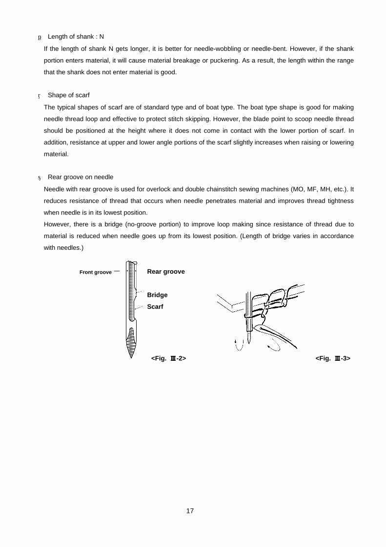
⑧ Rear groove on needle
Needle with rear groove is used for overlock and double chainstitch sewing machines (MO, MF, MH, etc.). It
reduces resistance of thread that occurs when needle penetrates material and improves thread tightness
when needle is in its lowest position.
However, there is a bridge (no-groove portion) to improve loop making since resistance of thread due to
material is reduced when needle goes up from its lowest position. (Length of bridge varies in accordance
with needles.)
<Fig. ⅢⅢⅢⅢ-2> <Fig. ⅢⅢⅢⅢ-3>
Rear groove
Bridge
Scarf
Front groove

18
⑨ Shape of needle tip Shape of needle tip <Table ⅢⅢⅢⅢ-2>
Shape of
point
Sharp and slim
type point SPI Light-weight fabrics, light-weight
leather Regular type
point R General fabrics
Butt type point BUT Mainly for button sewing
Slim point S Slim shape and J point at needle
tip, for high-gauge knit
J ball point J For general knit, suitable for
standard material as well
B ball point B For relatively coarse knit, Ball is
φ1/5 of trunk
U ball point U For knit and power-net, Ball is
φ1/3 of trunk
Y ball point Y For elastic materials, Ball is φ1/2
of trunk
Flat tip shape
LL
LR
45゚ twisted type knife needle
Mainly for leather goods
45゚ reversely twisted knife needle
* For the overseas version of the needle tip point, refer to "Reference data 3" in the end of this volume.(P.63) ⑩ Exclusive needle for knit
This is a needle that does not break material with its tip, and this is improved penetration of needle to
material.
It is effective against material breakage and protection of puckering. -1 : KN needle (for high-gauge knit material)
-2 : SF needle (for ultra fine-gauge knit)
This needle is slimmer by one size than KN needle from needle tip to near to eyelet.
Tip point Symbol Shape of needle tip Application and feature
DBx1 KN
<Fig. ⅢⅢⅢⅢ-4> Tip is longer by 0.5 mm to 1 mm.
Slim shape and ball point (regular point J, optional points B, U and Y)
Eyelet is as large as that of the standard type.
Trunk is not a 2-step streteched
Long taper

19
⑪ Needle for new synthetic fiber (NS needle)
This is a needle that resistance of needle penetration of the exclusive needle for knit is further recuced, and
is useful for puckering prevention.
Shape is almost the same as that of SF needle, but sharp-pointed from needle tip which makes resistance
of needle penetration the least. ⑫ Surface treatment -1 Nickel plating
This plating is full of corrosion resistance and generally used for the home-use sewing machine. -2 Chrome plating
Generally, hard chrome plating is made on the needle, and the needle is superior in heat-proof and wear
proof. The needle is used for the industrial sewing machine.
-3 Teflon coating Slide is the best, but durability of coating effect is low.
-4 Titanium coating Wear proof and heat-proof are best, and this needle is used for extra heavy-weight material or the like.
⑬ Needle-to-thread relation 【 How to check proper needle size 】
Pass thread used of an appropriate length (approx. 50 cm) through needle,
hold both ends of the thread, stretch it vertically as shown in the illustration
and slide the needle. When the needle slides down while slowly turning, it can be said that the size
of needle is proper for the thread.
If the needle does not slide down or slides down without any resistance, stitch
failure (stitch skipping, thread breakage or stitch looseness) is likely to occur.
Table of proper relations between needle and thread <Table ⅢⅢⅢⅢ-3> Needle size Spun thread Filament thread Main application #5 to #6 #120 #100 Extra light-weight nylon material and blouses #7 to #8 #100 #80 to #100 Shirts, knit wear #9 to #10 #80 #60 to #80 Ladies' dress, pyjamas #11 to #12 #60 #50 to #60 Gents' suits, students' uniform #13 to #14 #40 to #50 #40 to #50 Wool fabrics, gents' suits #16 #30 to #40 #30 to #40 Working wear, jeans #18 #20 to #30 #20 to #30 Jeans, coat #19 #10 to #20 #10 to #20 Heavy-weight materials such as denim, sheet, etc. #20 to #21 #8 to #10 #5 to #10 Heavy-weight materials such as tent, sheet, etc. #22 to #26 #8 or less #5 or less Extra heavy-weight materials such as canvas or the like
<Fig. ⅢⅢⅢⅢ-5>
Thread

20
⑭ Kind of needle and applicable model <Table III-4>Kind of needle and applicable model <Table ⅢⅢⅢⅢ-4>
Size and
shape of needle tip
DB x 1 #7 to #25 General sewing
DB x 1738 #8 to #22 Ditto, Scarf is longer than that of DB x 1.
DB x 1KN #8 to #14 (J) For knit, trunk is smaller by one size and needle tip is slim.
DB x 1SF #9 to #11 (J) For ultra fine knit, resistance of penetration is smaller than KN.
DB x 1NS #8 to #11
(SPI)
For new synthetic fiber, resistance of penetration is the least.
DB x K5 #9 to #18 For embroidery and thick needle, eyelet is larger by two sizes.
DB - K23 #9 to #12 (J) For knit stitch, eyelet is larger than that of KN.
DB - N20 #11, #14, #16 For heavy-materials, Shank is shorter by approx. 3 mm than that of DB x 1.
DB x A20 #19 to #23 For heavy-materials, shank diameter is 1.62 mm.
General 1-needle
lockstitch sewing
machine
DDL-5530N
DDL-5550N
DDL-5700
DB x 1ST #20, #22 (J) For decorative stitch, trunk is smaller by one to two sizes and eyelet is larger by
two to three sizes.
DB x 3ST #11 to #22 (J) For decorative stitch, shank of #19 or less is 2.02 mm.
Trunk is smaller by one to two sizes and eyelet is larger by two to three sizes.
DDL-201S,
DU-141S
DA x 1 #7 to #22 For light-weight materials sewing by 1-needle lockstitch sewing machine DDL-5550NA
or the like
DA x 1KN #8, #9 (J) For light-weight materials sewing, trunk is smaller by one size and needle tip is
slim.
For knit
DP x 5 #6 to #25 For general special machines, N = 11.50 to 12.50
DP x 5KN #9 to #12 (J) For knit, trunk is smaller by one size and needle tip is slim.
DP x 134 #9 to #18 Shank is longer by 1 mm and scarf is of boat type.
DP x 7 #8 to #25 Shank is shorter by 1 mm and N = 11 mm fixed.
DP x 17 #9 to #26 For 2-needle lockstitch, it is longer by 5 mm than DP x 5.
LK-1900
LBH-790RS-1
LH-3128-7
LZ-2280N-7
AMS
DP - N31 #14, #16, #18 For 1st process of lockstitch button sewing,
Shank is shorter by 4.5 mm than that of DP x 17.
LK-1851-555
DC x 27 #6 to #24
(J up to #11)
For overlock machine, Scarf is of boat type (stitch skipping prevention)
DC - J27 #9 to #16 No rear groove on needle (stitch skipping prevention)
DC x 1 #7 to #25
(J up to #11)
For overlock machines, No scarf on #7 to #8
DC x 1KN #8 to #14 (J) For knit, Scarf is of boat type. Trunk is smaller by one size and needle tip is
slim.
DC - N17 #6 to #19 For blind overedging, Shank is longer by 3 mm (needle vibration prevention).
DC - N25 #7 to #11 For blind overedging, Shank is longer by 1.5 mm (needle vibration prevention).
General overlock
machines
MO
MOR
MOC
MOF
Kind Main application Applicable model
*For the common needle symbols to SCHMETZ and others, refer to "Reference data 4" in the end of this volume.(P.64)
21
Size and
shape of needle tip
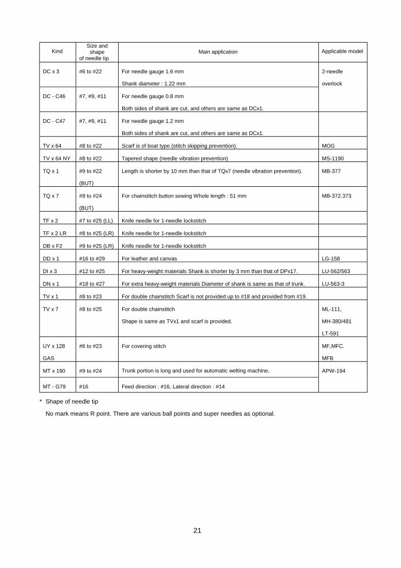
DC x 3 #6 to #22 For needle gauge 1.6 mm
Shank diameter : 1.22 mm DC - C46 #7, #9, #11 For needle gauge 0.8 mm
Both sides of shank are cut, and others are same as DCx1.
2-needle
overlock
DC - C47 #7, #9, #11 For needle gauge 1.2 mm
Both sides of shank are cut, and others are same as DCx1.
TV x 64 #8 to #22 Scarf is of boat type (stitch skipping prevention). MOG TV x 64 NY #8 to #22 Tapered shape (needle vibration prevention) MS-1190
TQ x 1 #9 to #22
(BUT)
Length is shorter by 10 mm than that of TQx7 (needle vibration prevention). MB-377
TQ x 7 #9 to #24
(BUT)
For chainstitch button sewing Whole length : 51 mm MB-372.373
TF x 2 #7 to #25 (LL) Knife needle for 1-needle lockstitch
TF x 2 LR #8 to #25 (LR) Knife needle for 1-needle lockstitch
DB x F2 #9 to #25 (LR) Knife needle for 1-needle lockstitch
DD x 1 #16 to #29 For leather and canvas LG-158
DI x 3 #12 to #25 For heavy-weight materials Shank is shorter by 3 mm than that of DPx17. LU-562/563
DN x 1 #18 to #27 For extra heavy-weight materials Diameter of shank is same as that of trunk. LU-563-3
TV x 1 #8 to #23 For double chainstitch Scarf is not provided up to #18 and provided from #19.
TV x 7 #8 to #25 For double chainstitch
Shape is same as TVx1 and scarf is provided.
ML-111,
MH-380/481
LT-591
UY x 128
GAS
#6 to #23 For covering stitch MF,MFC.
MFB
MT x 190 #9 to #24 Trunk portion is long and used for automatic welting machine.
MT - G79 #16 Feed direction : #16, Lateral direction : #14
APW-194
* Shape of needle tip
No mark means R point. There are various ball points and super needles as optional.
Kind Main application Applicable model

22
DB type
Horizontal full rotary
hook
(Horizontal 2-rotation
hook)
DDL-5550N, LZ-586U, etc.
This hook is vertically set to hook driving shaft, and hook driving
shaft rotates two times when needle bar travels one time.
This hook is used the most for the industrial sewing machine and
there are many kinds.
・Normal feed : perfect stitch
・Reverse feed : hitch stitch
DP type
Horizontal full rotary
hook
(Horizontal 2-rotation
hook)
LBH-770-1, LBH-790RS-1, LZ-2280N-7
This hook is used for zigzag sewing and embroidery sewing
machines since perfect stitch can be obtained regardless of
sewing direction.
・Rotation is reverse to that of DB type.
・It is apt to occur that thread is caught on race surface.
Vertical full rotary hook
(Vertical 2-rotation hook)
LH-3128-7, LU-563N, LU-2210N-7, etc.
This hook is developed for 2-needle sewing machine, but used
for sewing machine with 1-needle to sew heavy-weight materials.
・Regardless of sewing direction, perfect stitch can be obtained.
・Opener (thread handling) is required to improve slide of upper
thread.
Horizontal semi-rotary
hook (Inner hook)
LK-1900, LK-1850, AMS Series
・This hook is suitable for heavy-weight materials since
correspondence to change of material thickness is good.
・This is not suitable for high-speed because of oscillating
motion.
・Perfect and hitch stitches are made.
Shuttle hook
TSU-471, 421, 441 ・Stitches are well-tightened. This is suitable for sewing shoes,
bags, etc. ・Perfect and hitch stitches are made.。
2. Hook
1) Function ① Hook is divided into outer hook and inner hook. Outer hook scoops upper thread from needle, rotates
periphery of inner hook and interlaces with lower thread (bobbin case) which is set to inner hook to form
stitches. ② Semi-rotary hook scoops upper thread with the inner hook. 2) Kind of hook <Table ⅢⅢⅢⅢ-5>

23
3) Full rotary hook Full rotary hook is roughly divided into DB type and DP type. ① Difference between DB type and DP type <Table ⅢⅢⅢⅢ-6> DB type DP type Rotating direction as observed from the front
of hook Left-hand rotation Right-hand rotation
Position of needle thread and blade point in
terms of bobbin thread Bobbin thread, needle, blade
point Bobbin thread, blade point,
needle Needle thread pulled in hook (needle side) Needle thread rotates around
rear side of inner hook. Needle thread rotates around
front side of inner hook. Normal feed Perfect stitch Perfect stitch
Reverse feed Hitch stitch Perfect stitch
<Fig. ⅢⅢⅢⅢ-6>
<Fig. ⅢⅢⅢⅢ-8> <Fig. ⅢⅢⅢⅢ-9>
<Fig. ⅢⅢⅢⅢ-7>
Needle Needle
Lower thread
Lower thread
Blade point
Blade point
Perfect stitch Hitch stitch Needle thread
Cloth
Bobbin thread

24
<Fig. ⅢⅢⅢⅢ-11>
② Stitch type DB type hook
DP type hook (vertical hook)
<Fig. ⅢⅢⅢⅢ-10>
①
② ①
④ ③ ②
④ ③
①
①
②
②
③
③
④
④
Forward sewing
Backward sewing
Forward sewing
Backward sewing

25
<Fig. ⅢⅢⅢⅢ-13> <Fig. ⅢⅢⅢⅢ-12>
③ Upper thread motion of DB hook
c : Upper thread is separated to inner side and outer side of inner hook at thread separating portion of race.
d : Immediately before upper thread passes through inner hook
Swell at portion ② of H
type for thick thread and
heavy-weight materials is
largely swollen outward so
as to improve crossover of
thread on bobbin case.
Thread is well-tightened at
high-speed.
Also, lower thread is fed.
<Fig. ⅢⅢⅢⅢ-14> <Fig. ⅢⅢⅢⅢ-15>
<Fig. ⅢⅢⅢⅢ-16> <Fig. ⅢⅢⅢⅢ-17>
a : Blade point of outer hook catches upper
thread (loop). b : Upper thread moves into the inner
side of blade point following the
rotation of hook.
Needle side Material side
Blade point
Needle Material side
Needle side
Blade point
Material side Needle side
Thread separating portion of race
Outer side
Material side
Needle side Inner side
Needle side Material side
Bobbin case fixing pin
Material side
Needle side

26
l : Thread take-up lever starts lifting upper thread.
f : Thread comes off hook and is caught on the claw portion of inner hook presser.
④ Blade point of hook -1 Shape of blade point -2剣先強化釜
布布布布地地地地側側側側
針針針針側側側側
レース糸レース糸レース糸レース糸抜け部抜け部抜け部抜け部
針側針側針側針側
布地側布地側布地側布地側
内釜押え爪内釜押え爪内釜押え爪内釜押え爪布地側布地側布地側布地側
内釜押え爪内釜押え爪内釜押え爪内釜押え爪
布地側布地側布地側布地側針側針側針側針側
<Fig. ⅢⅢⅢⅢ-18>
<Fig. ⅢⅢⅢⅢ-19> <Fig. ⅢⅢⅢⅢ-20>
<Fig. ⅢⅢⅢⅢ-23> <Fig. ⅢⅢⅢⅢ-22> <Fig. ⅢⅢⅢⅢ-21>
<Fig. ⅢⅢⅢⅢ-25> <Fig. ⅢⅢⅢⅢ-24>
Material side Needle side
Material side
Needle side
Thread coming-off portion on race
Material side Claw of inner hook presser
Needle side
Material side
Claw of inner hook presser
Standard type Tear-drop type It is hard to be blunt.
SP type It is good for stitch skipping, but is apt to be blunt.
Hard point hook (HP hook) **** : Reinforcing agent is welded at tip portion.
Hard chrome plating hook (CR hook) **** : Hard chrome plating is made on the whole outer hook.

27
⑤Type of DB hook There are basic types of A, B, C, D, E, and F for DB hook. These types have the respective features.
Type A <Fig. ⅢⅢⅢⅢ-26>
This is for heavy-weight materials or zigzag
stitching, and thread coming-off timing is
most advanced, comparing with other types.
Accordingly, even when this is set at rather
delayed timing, thread coming-off from hook
is not so hard. Type B <Fig. ⅢⅢⅢⅢ-27>
This is a general type covering from
heavy-weight to light-weight materials. The
feature is that the claw of inner hook presser
is stretched long.
This claw holds needle thread for a relatively
long period of time when the thread comes
off from hook and works to get rid of the
excessive slack.
Accordingly, it is effective to protect looping (towel face which often occurs at the wrong side of material) when
using tightly-twisted thread or hard-to-slide thread. Type C <Fig. ⅢⅢⅢⅢ-28>
This is used for both medium-weight and light-weight materials and has a projection to protect thread bite
which prevents needle thread from entering into the gap between outer hook groove and hook race when the
thread comes off from hook. As shown in the illustration, thread rides on this projection to prevent from being
bit, and simultaneously is held to a certain extent by this projection to get rid of the excessive slack.
Further, whole length of outer hook gets long with this projection resulting in increasing durability and
protecting occurrence of hook noise. Type D <Fig. ⅢⅢⅢⅢ-29>
This combines the merit of type B and type C. Similar to type B, this has the claw of inner hook presser to hold
the slack of needle thread, and similar to type C, this has a projection to protect thread bite. Further, another
feature is that this is designed to reduce as much as possible the resistance when thread comes off from hook
by lightening weight of inner hook and reducing moment of inertia. Therefore, better stitching can be obtained
even for hard-to-sew thread such as slim and weak thread, synthetic thread, etc. Type BOH <Fig. ⅢⅢⅢⅢ-30>
This is for medium-weight and heavy-weight materials and designed so that even when using thick and
less-twisted soft thread, thread smoothly comes off and looping does not occur by shortening the claw of inner
hook presser.
<Fig. ⅢⅢⅢⅢ-27> <Fig. ⅢⅢⅢⅢ-26>
<Fig. ⅢⅢⅢⅢ-29> <Fig. ⅢⅢⅢⅢ-30> <Fig. ⅢⅢⅢⅢ-31>
<Fig. ⅢⅢⅢⅢ-28>
A B C
D E F

28
Type F <Fig. ⅢⅢⅢⅢ-31> This is developed for semi-industrial sewing machine. The type belongs to type A. However, the feature is that
inner hook presser is constructed (jam proof) to be assembled with a screw through coil spring. Even when
thread bite occurs during sewing, thread bit in hook can be taken out without disassembling the hook. There is
a hook in this type that can perform zigzag stitching of home-use sewing machine.
Type HSM (double-capacity hook) Bobbin is made large to improve sewing efficiency and amount of thread winding is double as much as the
standard when using thick bobbin thread or the like. This can be used for heavy-weight material, stitch sewing,
etc. Type HST (3-fold capacity hook)
Amount of bobbin thread winding is approximately three times as much as the standard to improve further
sewing efficiency of extra thick thread or extra heavy-weight materials. There are two kinds of type A and type
B which can be used for the exclusive sewing machine to sew pattern stitching or the like in accordance with
the application.
4) Needle guide of hook
Needle guide is attached to hook excluding exception. Needle guide is the most important part to protect
blade point of hook and keep hook from damage, and also plays an role of protecting needle breakage.
The following table gives typical examples of needle guide.
Type and characteristics of needle guide <Table ⅢⅢⅢⅢ-7> Type Illustration Description
DB series
Generally, this needle guide is used without applying needle
guard (up to #21). However, there is a needle guard type
needle guide corresponding to thin needle (up to #11) as well.
DP series
This needle guide is attached to DP series hook and the
portion of needle guide can be adjusted in accordance with
thickness of needle.
12 series
11 series
This needle guide is attached to hook for relatively light-weight
materials of 2-needle vertical hook. Portion of needle guide
can be adjusted in accordance with thickness of needle.
29
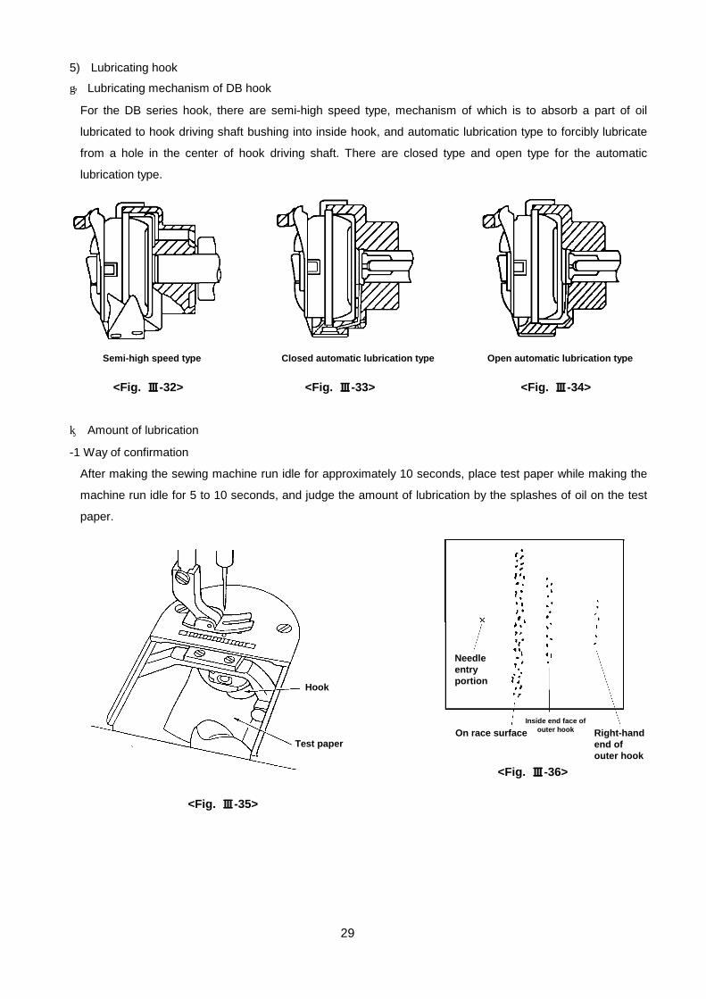
5) Lubricating hook ① Lubricating mechanism of DB hook
For the DB series hook, there are semi-high speed type, mechanism of which is to absorb a part of oil
lubricated to hook driving shaft bushing into inside hook, and automatic lubrication type to forcibly lubricate
from a hole in the center of hook driving shaft. There are closed type and open type for the automatic
lubrication type.
② Amount of lubrication -1 Way of confirmation
After making the sewing machine run idle for approximately 10 seconds, place test paper while making the
machine run idle for 5 to 10 seconds, and judge the amount of lubrication by the splashes of oil on the test
paper.
<Fig. ⅢⅢⅢⅢ-34>
<Fig. ⅢⅢⅢⅢ-35>
<Fig. ⅢⅢⅢⅢ-33>
<Fig. ⅢⅢⅢⅢ-36>
<Fig. ⅢⅢⅢⅢ-32>
Semi-high speed type Closed automatic lubrication type Open automatic lubrication type
Hook
Test paper
Needle entry portion
Inside end face of outer hook On race surface Right-hand
end of outer hook

30
-2 Appropriate amount of oil
Appropriate amount of oil for 5 seconds is such an extent as shown in the above right-hand illustration.
Necessary places of oil are especially on race surface and oil splashes slightly in the inside end face of outer
hook and right-hand end of outer hook.
* When thick thread or hard-to-slide thread is used.
Thread tightness is improved when increasing the amount of lubrication to such an extent that oil is not
attached to the sewing products.
* When thin thread or especially, synthetic thread is used.
It is better to decrease amount of lubrication to such an extent that hook is not seized. However, seizure of
race surface occurs if amount of oil is excessively decreased.
As a result, motion of inner hook is deteriorated, and hook noise or hook temperature is increased. Also, dirt
of needle thread (thread gets dark) may occur.
-3 Rise of hook temperature
Temperature of hook which rotates
at high speed rises, however, the
extent of rise of temperature varies
in accordance with number of
revolutions, continuous rotating time
and amount of lubrication.
Rise of hook temperature should not
be worried except for abnormal
cases. However, it should be careful
about the lubricating condition
<Fig. ⅢⅢⅢⅢ-37>
Tempera
ture (゚゚゚゚C)
Automatic lubrication type hook (amount of lubrication is fixed.)
Rise of hook temperature
Time (minute)

31
6) Hook timing When timing marks are attached to needle bar, make sure that
upper line of timing mark is aligned with lower end of needle bar
bushing in the state that needle bar is lowered to its lowest
position.
When they are not aligned with each other, adjust the position of
needle bar. Next, when needle bar goes up from its lowest position
and lower line of timing mark is aligned with lower end of needle
bar bushing, adjust blade point of hook to the center of needle to
attach the hook.
b = Hook timing (phase)
c = Position of needle bar (height)
a = b + c
When DDL-5550N is adjusted to the timing marks, the respective values are :
a = 3.0 mm, b = 2.0 mm, and c = 1.0 mm.
It may be required to change the adjustment values in accordance with materials (cloth and thread).
7) Needle thread loop -1 When needle goes up from its lowest
position, loop is formed by resistance of cloth.
-2 Size and shape of loop a : Loop is small. ・Lifting amount is small.
・Thread is bad. → Stretch of thread is excessive.
・Cloth is flopped → Fixing of cloth is bad. (Overlapped portion or the like)
Resistance is excessively strong. (Needle pierces material yarn, or the like.)
・Resistance of cloth is small. → Texture is coarse.
Extra light-weight materials.
Needle is too thick. ・Resistance of cloth is excessive. (Since thread is stretched.)
→ Extra heavy-weight materials
Resistance of penetration is high.
<Fig. ⅢⅢⅢⅢ-38>
Needle bar bushing
Timing mark
Blade point of
Needle lowest position
<Fig. ⅢⅢⅢⅢ-39>
Size of loop
Lifting amount Lowest position
<Fig. ⅢⅢⅢⅢ-41>
Flopped
Loop is small
Lifting amount
Lowest position
<Fig. ⅢⅢⅢⅢ-40>
Thick cloth (overlapped portion)
Small loop
Lowest position
Lifting amount : small
32
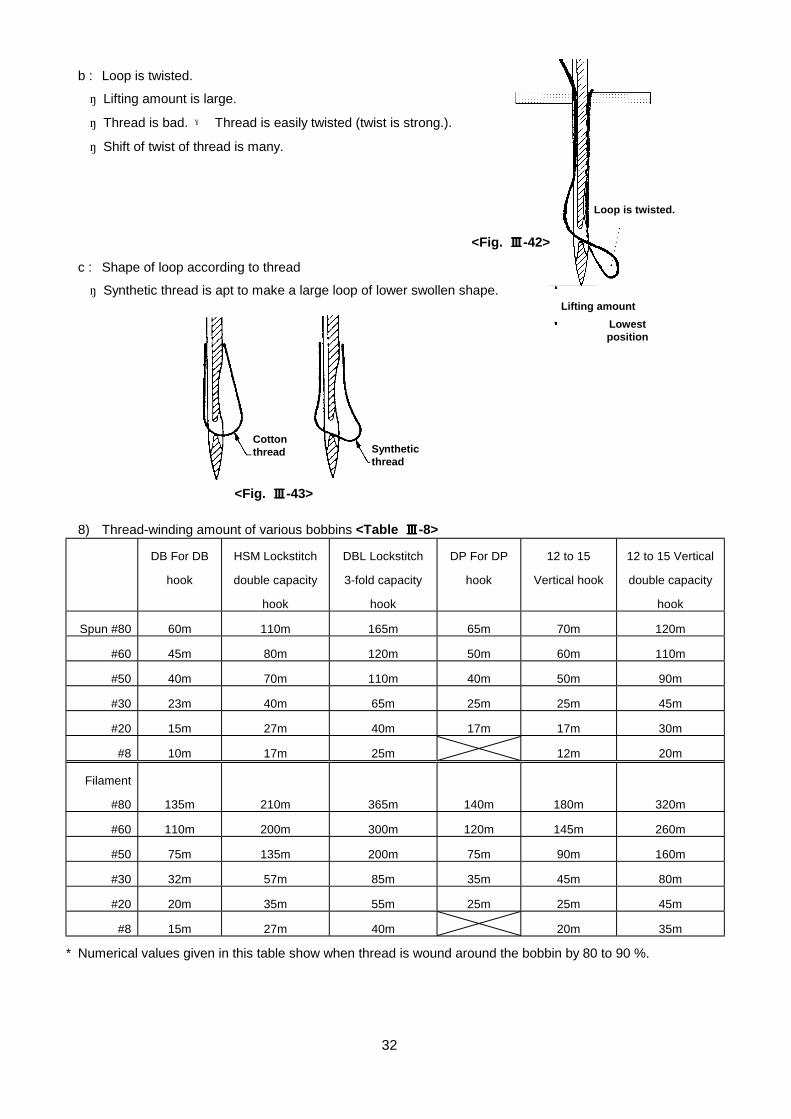
b : Loop is twisted.
・ Lifting amount is large.
・ Thread is bad. → Thread is easily twisted (twist is strong.).
・ Shift of twist of thread is many.
c : Shape of loop according to thread
・ Synthetic thread is apt to make a large loop of lower swollen shape.
8) Thread-winding amount of various bobbins <Table ⅢⅢⅢⅢ-8> DB For DB
hook
HSM Lockstitch
double capacity
hook
DBL Lockstitch
3-fold capacity
hook
DP For DP
hook
12 to 15
Vertical hook
12 to 15 Vertical
double capacity
hook
Spun #80 60m 110m 165m 65m 70m 120m
#60 45m 80m 120m 50m 60m 110m
#50 40m 70m 110m 40m 50m 90m
#30 23m 40m 65m 25m 25m 45m
#20 15m 27m 40m 17m 17m 30m
#8 10m 17m 25m 12m 20m
Filament
#80
135m
210m
365m
140m
180m
320m
#60 110m 200m 300m 120m 145m 260m
#50 75m 135m 200m 75m 90m 160m
#30 32m 57m 85m 35m 45m 80m
#20 20m 35m 55m 25m 25m 45m
#8 15m 27m 40m 20m 35m
* Numerical values given in this table show when thread is wound around the bobbin by 80 to 90 %.
<Fig. ⅢⅢⅢⅢ-42>
<Fig. ⅢⅢⅢⅢ-43>
Loop is twisted.
Lifting amount Lowest position
Cotton thread Synthetic
thread

33
3. Thread take-up lever 1) Function
① Provides needle with upper thread.
② Supplies necessary amount of thread so that hook can scoop upper thread
and so that the upper thread can pass through inner hook.
③ Lifts upper thread quickly when upper thread passes through inner hook.
④ Feeds out upper thread to be consumed for stitches together with feed dog.
⑤ Performs thread-tightening.
2) Kind of thread take-up lever
① Cam type thread take-up lever <Fig. ⅢⅢⅢⅢ-44>
Thread take-up lever moves up and down by means of cam fixed on main shaft.
Thread tightening is very finely performed, and this type is largely used for
leather and heavy-weight materials.
This is used for the old home-use sewing machines. In addition, this is not
suitable for high-speed.
③ Slide type thread take-up lever <Fig. ⅢⅢⅢⅢ-46>
Slide shaft of thread take-up lever is rotated by means of rotary motion of main
shaft and thread take-up lever moves up and down. This makes good thread
tightening and is used with vertical hook for heavy-weight materials.
However, this is not suitable for high-speed. (Approx. up to 3,500 spm)
⑤ Rotary thread take-up lever <Fig. ⅢⅢⅢⅢ-48>
Blade-like thread take-up lever is rotated by means of rotation of counter weight
mounted to main shaft and loosening and lifting of upper thread can be performed.
This makes good-looking stitch tightness and is used largely for zigzag stitching
(foundation).
② Link type thread take-up lever <Fig. ⅢⅢⅢⅢ-45>
Thread take-up lever crank is rotated by means of rotary motion of
main shaft and thread take-up lever moves up and down.
This type is used the most for general lockstitch sewing machines.
④ Needle bar type thread take-up lever <Fig. ⅢⅢⅢⅢ-47>
This is directly mounted to needle bar and performs same motion as
that of needle bar. This is used for chainstitch sewing machines.
<Fig. ⅢⅢⅢⅢ-44>
Thread take-up setscrew
Thread take-up lever
Thread take-up lever roller
Cam
<Fig. ⅢⅢⅢⅢ-45>
Thread take-up lever support shaft
Thread take-up lever eyelet
Swivel pin
Thread take-up lever crank
Track of thread take-up lever crank
Main shaft
<Fig. ⅢⅢⅢⅢ-46>
Thread take-up lever eyelet
Slide shaft of thread take-up lever
Track of slide shaft of thread take-up lever
Main shaft
<Fig. ⅢⅢⅢⅢ-47>
Thread take-up lever
Needle bar
<Fig. ⅢⅢⅢⅢ-48>
Blade thread take-up lever

34
3) Stroke of thread take-up lever (Thread supply amount)
Thread supply amount from upper dead point to lower dead point of thread take-up lever is called stroke of
thread take-up lever. Normally, the stroke is small for light-weight materials and large for heavy-weight
materials. When the stroke is small, thread tightness is improved.
For the adjustment of stroke of thread take-up lever, it can be performed by moving arm thread guide
laterally or vertically.
When sewing heavy-weight materials, move thread guide to the left or lower direction to increase thread
supply amount. When sewing light-weight materials, move thread guide to the right or upper direction to
decrease thread supply amount. For the standard adjustment of thread guide, thread guide should be
positioned in a way that engraved marker line is aligned with the center of screw.
4) Motion diagram
This diagram shows the static motion of 360゚ per rotation, while making needle bar upper dead point as 0゚,
regarding the motion of needle bar and feed dog, how hook draws needle thread, how needle thread passes
through hook, and how thread take-up lever supplies and lifts needle thread.
<Fig. ⅢⅢⅢⅢ-50>
<Fig. ⅢⅢⅢⅢ-51>
<Fig. ⅢⅢⅢⅢ-49>
Thread supply amountIncrease D
Thread guide
Thread supply amount
Decrease
Increase
Thread tightness variation by stroke of thread take-up lever
Thread tightness ====variation %
Upper thread length Lower thread length
x 100
Thread tightness variation
Small Medium Large
Stroke of thread take-up lever
Needle bar
stroke
Feed dog upper dead point
Needle bar upper dead point
Rotation angle
(Example) General lockstitch sewing machine
Curve of needle bar motion
Thread take-up lever upper dead point
Feed dog lower dead point
Needle bar low
er dead point
Curve of thread supply of thread take-up lever U
pper thread catching by hook
Curve of hook thread take-up
Thread take-up lever lower
dead point
Curve of feed dog vertical motion
Upper thread from
hook
Threadtake-up
lever

35
4. Feed dog
1) Function
① Makes the sewing product move per stitch.
② Can change amount to move and forms stitches suitable for the sewing product.
③ Stretch stitching or gathering stitching can be performed by means of feed mechanism, and prevention of
puckering, gathering, etc. can be performed.
2) Kind of feed mechanism
① Bottom feed
This is the most standard feed mechanism, which feeds material with lower feed
dog only.
Uneven material feeding is likely to occur because of bottom feed only. However,
sharp curve stitching can be easily performed and material handling is easy.
② Needle feed (Bottom feed + needle feed)
This is the feed mechanism which needle bar moves in synchronization with bottom
feed. Feeding force is strong, and this type can feed material more precisely than
the aforementioned bottom feed type sewing machine. Uneven material feeding is
reduced, but, stitch shrinking due to thread tightness is likely to occur.
③ Differential feed (Front bottom feed + rear bottom feed)
This is the bottom feed mechanism, but feed dog is divided into front and rear.
This is the feed mechanism which is possible to intentionally stretch material or
gather material by changing feed amount of front feed dog and rear feed dog. This
is suitable for sewing elastic knit.
Differential feed ratio of MO (overlock sewing machine)
Gathering 1 : 2 (Max. 1 : 4)
Stretching 1 : 0.7 (Max. 1 : 0.6)
④ Bottom and variable top feed (bottom feed + top differential feed)
There is a feed dog on the top side in terms of bottom feed, and top feed amount
can be adjusted simultaneously together with adjustment of material feed from the
bottom side.
Accordingly, this is the feed mechanism which is possible to prevent sewing
slippage, and to perform edging contracting or gathering.
<Fig. ⅢⅢⅢⅢ-52>
<Fig. ⅢⅢⅢⅢ-53>
<Fig. ⅢⅢⅢⅢ-55>
<Fig. ⅢⅢⅢⅢ-54>

36
⑤ Differential bottom feed and variable top feed
(differential feed + top differential feed)
Bottom feed is differential feed, and top feed amount can be adjusted
simultaneously together with adjustment (stretching and gathering) of
material feed from the bottom side. Accordingly, this is the suitable
mechanism which can give most suitable feed amount to the upper and
lower materials.
⑥ Unison feed (bottom feed + top feed + needle feed)
Feed force of this mechanism is most superior and this feed mechanism is
largely used for extra heavy-weight materials or the like.
⑦ Others
・ With cloth pulling roller ... Roller located in the rear of presser foot pulls
materials and sewing is performed. Uneven
material feeding is reduced and working
property is improved.
・ Fixed feed ... This is the feed mechanism to feed materials in a fixed
state by holding materials between lower plate and upper
plate.
(Example : cycle machine and automatic machine)
<Fig. ⅢⅢⅢⅢ-56>
<Fig. ⅢⅢⅢⅢ-57>
<Fig. ⅢⅢⅢⅢ-58>
<Fig. ⅢⅢⅢⅢ-59>

37
3) Kind of feed dog
① Angle feed dog ... This is a feed dog generally used in large.
The shape is strong in feed force of normal
feed.
② Double-cut feed dog ... It is good to fix materials laterally.
This is used for upper feed dog of
zigzag sewing machine, and top and
bottom feed sewing machine.
③ Slant tooth (helical tooth) feed dog ... The shape is hard to make feed dog defect on materials. This is used
for top and bottom feed sewing machine (cloth puller type).
④ Urethane rubber feed dog ... Feed dog defect is not made on materials.
This is suitable for materials on which feed dog defect is easily made or yarn
of cloth is caught with feed dog.
4) Shape of feed dog (with respect to angle feed dog)
① Shape of top end
・ Sag at the top end of tooth (width is 0.1 mm or more and
rounding)
Catching of material is deteriorated and decrease of feed force,
uneven pitch or material slippage will occur.
Corrective measure : Grind the top end using grind stone or the
like.
・ Top end of tooth is sharp as a blade.
Scratch on material, thread breakage or chain-off thread breakage
will occur.
Corrective measure : Lightly grind the surface of tooth using grind
stone or the like and buff there.
・ Surface of feed dog is not even. Or, it is not levelled.
Corrective measure : Correct it using grind stone or the like.
Feed dog comes in single-side contact with materials and straight
feeding is deteriorated.
Corrective measure : correct using grnid stone or the line.
<Fig. ⅢⅢⅢⅢ-60>
<Fig. ⅢⅢⅢⅢ-61>
<Fig. ⅢⅢⅢⅢ-62>
<Fig. ⅢⅢⅢⅢ-63>
<Fig. ⅢⅢⅢⅢ-64>
38
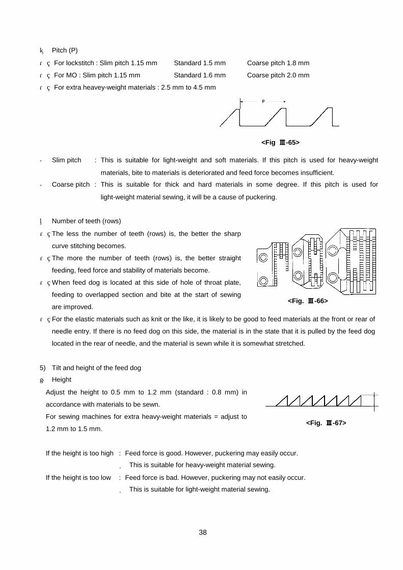
② Pitch (P)
・ For lockstitch : Slim pitch 1.15 mm Standard 1.5 mm Coarse pitch 1.8 mm
・ For MO : Slim pitch 1.15 mm Standard 1.6 mm Coarse pitch 2.0 mm
・ For extra heavey-weight materials : 2.5 mm to 4.5 mm
◎ Slim pitch : This is suitable for light-weight and soft materials. If this pitch is used for heavy-weight
materials, bite to materials is deteriorated and feed force becomes insufficient.
◎ Coarse pitch : This is suitable for thick and hard materials in some degree. If this pitch is used for
light-weight material sewing, it will be a cause of puckering.
③ Number of teeth (rows)
・ The less the number of teeth (rows) is, the better the sharp
curve stitching becomes.
・ The more the number of teeth (rows) is, the better straight
feeding, feed force and stability of materials become.
・ When feed dog is located at this side of hole of throat plate,
feeding to overlapped section and bite at the start of sewing
are improved.
・ For the elastic materials such as knit or the like, it is likely to be good to feed materials at the front or rear of
needle entry. If there is no feed dog on this side, the material is in the state that it is pulled by the feed dog
located in the rear of needle, and the material is sewn while it is somewhat stretched.
5) Tilt and height of the feed dog
① Height
Adjust the height to 0.5 mm to 1.2 mm (standard : 0.8 mm) in
accordance with materials to be sewn.
For sewing machines for extra heavy-weight materials = adjust to
1.2 mm to 1.5 mm.
If the height is too high : Feed force is good. However, puckering may easily occur.
⇒ This is suitable for heavy-weight material sewing.
If the height is too low : Feed force is bad. However, puckering may not easily occur.
⇒ This is suitable for light-weight material sewing.
<Fig ⅢⅢⅢⅢ-65>
<Fig. ⅢⅢⅢⅢ-67>
<Fig. ⅢⅢⅢⅢ-66>

39
① Tilt
Generally, it is the standard that the
feed dog is flush with throat plate
surface when the feed dog goes up
from throat plate surface or it comes
down from throat plate surface.
When tilting the feed dog with its
anti-operator's side up (up in the
opposite side of needle), cloth puller effect appears and puckering decreases.
6) Feed timing
Check the timing at the position where needle tip ((needle eyelet) is when feed dog comes down.
① When feed timing is advanced <Fig. ⅢⅢⅢⅢ-70>
If the feed timing is advanced when thread is pulled up with thread take-up lever, thread is caught between
throat plate and material and thread tightness is deteriorated.
② When feed timing is delayed <Fig. ⅢⅢⅢⅢ-71>
Bending of thread is decreased and upper thread tightness is improved. However, if feed timing is excessively
delayed, needle wobbling occurs, resulting in needle breakage.
引っ張る
伸ばされる押えと針板で布地を押さえ
る
布地針板
反作業者上がり
(送り上昇時)水平
布地
布地をしっかり押さえてから送る。
<Fig. ⅢⅢⅢⅢ-68>
Pull Stretched
Press material with presser foot and throat plate
Anti-operator's side up
Material Throat plate
Feed material after securely pressing it. Material
(When feed dog goes up.) Level
針板上面針板上面針板上面針板上面 針板上面針板上面針板上面針板上面 針板上面針板上面針板上面針板上面
<Fig. ⅢⅢⅢⅢ-69>
Surface of throat plate
(Advanced feed timing)
Surface of throat plate
(Standard feed timing)
Surface of throat plate
(Delayed feed timing)
<Fig. ⅢⅢⅢⅢ-71> <Fig. ⅢⅢⅢⅢ-70>
Feed timing is advanced.
Upper thread is caught between throat plate and material.
Thread take-up lever pulls up thread.
Material
Throat plate
Feed timing is delayed.
Bending of thread is decreased.
Thread take-up lever pulls up thread.
Material
Throat plate

40
5. Presser foot
1) Function
① Stabilizes materials to sew jointly on the surface of throat plate, and determines the sewing position.
② Presses the materials so that materials are not lifted with the needle when needle comes out of materials.
③ Makes materials come in close contact with teeth of feed dog with adequate pressure so that the sewing
direction is not disturbed when feed dog feeds materials forward or backward.
2) Kind of presser foot There are many kinds of presser foot so that it can be used properly in
accordance with kind of material or sewing process.
Kinds of the typical presser foot are described as follows.
① Hinging presser foot
This is the most standard presser foot, and a spring is mounted in the rear
of the presser foot so that its front part is up. This corresponds well to
materials and feeding at overlapped section is smooth.
② Fixed presser foot
This is largely exclusively used for 2-fold, 3-fold piping, etc. Stability of
folding or the like is good, however, feeding at overlapped section is
deteriorated.
③ Compensating presser foot
This is a guide presser exclusively used for stitch sewing. There are
three shapes for left-side overlapped section, right-side overlapped
section and use of both sides. There are many kinds so as to
correspond with numerous stitch widths.
④ Sliding presser foot
This presser foot moves forward or backward by means of up/down of
feed dog, and it is effective to prevent uneven material feeding.
(MH-481 : B1524-481-CD0)
(For general lockstitch sewing machine : B1524-227-AA0)
(For general lockstitch sewing machine : MAA-015000A0
= Front/rear adjutment of foot sole type)
自由押え自由押え自由押え自由押え
バネ
巻き部
固定押え固定押え固定押え固定押え
段付き押え段付き押え段付き押え段付き押え
スライディング押えスライディング押えスライディング押えスライディング押え
<Fig. ⅢⅢⅢⅢ-72>
<Fig. ⅢⅢⅢⅢ-73>
<Fig. ⅢⅢⅢⅢ-74>
<Fig. ⅢⅢⅢⅢ-75>
Spring
Hinging presser foot
Folding section
Fixed presser foot
Compensating presser foot
Sliding presser foot

41
⑤ Other special presser feet
・ Roller presser :
This is used for leather sewing. Rotating roller synchronizing with
bottom feed instead of presser sole is located at the side of needle
entry, and presses and feeds materials to be sewn.
This can be called a kind of top and bottom feed.
・ Ring roller presser :
Nylon rings attached to both sides of presser rotate in
synchronization with bottom feed, and feed materials.
This can be called a kind of top and bottom feed.
3) Thread path recess
Recess on the wrong side of presser foot is made to decrease resistance and lift the thread smoothly when
thread take-up lever lifts upper thread.
Length of this recess varies according to the kind of presser foot. It is necessary to use a proper presser foot in
accordance with thickness of thread or stitch length.
① Large recess
(DDL-5530N, DDL-5550N standard : B1524-012-0BA)
This type does not press stitch (knotting point of upper and lower
threads), and thread tightness is improved. However, if this presser foot
is used when stitch length is small or sewing light-weight materials,
puckering may occur.
Recommended feed pitch is approximately 4 mm.
② Small recess
(DDL-5550NA for light-weight materials : D1524-555-DBA)
When feed pitch 3 mm exceeds, defective thread tightness is apt to
occur. It is necessary to replace the presser foot with one with large
recess or to grind the recess to make it longer.
Recommended feed pitch is 2 mm to 3 mm.
<Fig. ⅢⅢⅢⅢ-76>
<Fig. ⅢⅢⅢⅢ-77>
<Fig. ⅢⅢⅢⅢ-79>
<Fig. ⅢⅢⅢⅢ-78>
Large
Small

42
③ No recess
(For extra light-weight materials : B1524-012-TBA)
This is effective for preventing puckering caused by excessive thread
tightness when sewing extra light-weight materials. Be careful about
sudden defective thread tightness.
4) Surface treatment
① Standard presser foot : Nickel plating, chrome plating
② Special presser foot : Teflon presser foot ... This is effective to prevent uneven material feeding because
of smooth sliding. However, it is inferior in the wear proof
since the presser sole is teflon itself. (Presser sole only :
D1524-126-W0B)
(For lockstitch sewing machine : D1524-126-WBA)
Teflon treatment presser foot ... Smooth sliding presser sole of special light alloy including
teflon is used, and this is effective to prevent uneven material
feeding. And, this is superior to the teflon presser foot in the
wear proof.
For lockstitch sewing machine
MAA-05000AA0 (PF-1) = For standard sewing
MAA-05000BA0 (PF-2) = For medium- and heavy-weight
material sewing
MAA-05000CA0 (PF-3) = For light-weight material sewing
5) Pressure of presser foot ① Relation between height of presser foot and pressure of presser foot <Table ⅢⅢⅢⅢ-9>
Pressure of presser foot : Kg 1 1.5 2 2.5 3 3.5 4 4.5 5 5.5 6
For light-weight
materials
B1505-227-T00A
40 36 33 30 27 24 21 19 Height of
presser
spring
regulator
mm For standard
B1505-227-000A
42 40 38 37 35 34 32 30 28 26
When the pressure of presser foot is high, feeding force is increased.
However, uneven material feeding or feed dog mark on the cloth is likely
to occur. Adjust the pressure to the lower level especially for the
light-weight material sewing or the like to sucn an extent that the material
feeding is not difficult.
Distance from top surface of sewing machine arm to top end of presser spring regulator (mm)
<Fig. ⅢⅢⅢⅢ-80>
No recess
Height of presser spring regulator
<Fig. ⅢⅢⅢⅢ-81>

43
② Kinds of presser spring
For standard sewing machine : B1505-227-000A (φ = 1.4 mm)
Pressure at the time of delivery : 4Kg When the strength ratio of this spring is regarded as [1],
For sewing machine for light-weight materials : B1505-227-T00A (φ = 1.2 mm) Pressure at the time of
delivery : 4Kg (type A)
1.5Kg (type E) Strength ratio to standard spring [0.57]
For sewing machine for extra light-weight materials : 111-62104 (φ= 1.0 mm) optional Strength ratio to
standard spring [0.28]
For NF sewing machine : 111-05202 (φ= 0.9 mm)
Pressure at the time of delivery : 1Kg Strength ratio to standard spring [0.19]
6. Thread tension
1) Function
This gives a proper tension to upper thread and lower thread among the various sewing conditions, and
interlaces upper thread and lower thread in the approximate center of cloth to form beautiful stitches.
2) Adjusting points of thread tension
First, adjust the lower thread tension.
Low tension ... it is effective for reduction of puckering, wobbling prevention, and improving appearance.
High tension ... it is effective for reduction of uneven stitches and decrease of bobbin idling.
① Measuring bobbin thread tension
Set bobbin case to the sewing machine as shown in the illustration, and draw up bobbin thread from the needle
hole in throat plate in the slanting upper direction of this side. Then, measure the tension at the unit of gf
(effective numerals : two digits) using tension gauge.
Set draw-out speed of thread to 10 to 30mm/sec.
Be sure to measure it in the state that the needle bar is near its upper dead point so that bobbin thread does
not come in contact with the outer hook.
* Notch for spring rotation prevention is attached to bobbin case with idling prevention spring, and the depth of
the case is wider than the standard as deep as the thickness of the spring (0.1 mm).
In case of springless bobbin case,
measuring may be performed at the
position of the above illustration. <Fig. ⅢⅢⅢⅢ-82>
<Fig. ⅢⅢⅢⅢ-83>
Idling prevention spring
Thread slit
Notch

44
Thread tension adjustment value <Table ⅢⅢⅢⅢ-10>
Bobbin thread
tension
Thread take-up
spring tension
Stroke (thread absorption
amount)
Spun #80 Tetoron #80, #60 10 to 25 g 5 to 15 g 9 to 14 mm
Spun #50, #60 Tetoron #50 15 to 30 g 10 to 20 g 8 to 13 mm
Spun #30 Tetoron #30 20 to 40 g 20 to 30 g 6 to 11 mm
Adjustment value of bobbin thread tension in terms of thread used for 1-needle lockstitch sewing
machine, thread take-up spring tension, or stroke (thread absorbing amount) slightly varies in
accordance with the sewing machines. Especially, stroke of thread take-up spring varies.
For the respective adjustments, refer to V) Adjustment procedures.
② Idling of bobbin
Idling bobbin causes the bobbin thread to come off as shown in the
illustration and thread breakage or irregular stitching occurs.
Corrective measures :
・Reduce bobbin thread winding amount.
・Replace with a lighter bobbin. (Aluminum bobbin or the like)
・Use a bobbin case with idling prevention spring.
・Decrease sewing speed.
・Use a bobbin case and a bobbin which are in the state that the clearance between them is small.
(Do not use the market-available ones.)
◎ Cause that idling occurs
-1 Idling at the time of thread trimming
Idling occurs since bobbin thread is quickly pulled when the
moving knife handles bobbin thread.
[Corrective measure other than the aforementioned corrective measures]
Adjust so that the bobbin positioning finger securely presses the bobbin at the time of thread trimming.
-2Idling due to vibration of sewing machine rotation
Bobbin of almost every sewing machine rotates in the hook rotating direction by the vibration. Therefore,
idling occurs.
<Fig. ⅢⅢⅢⅢ-85>
Bobbin
positioning
finger
<Fig. ⅢⅢⅢⅢ-86> Bobbin rotating
direction
Bobbin thread
comes off.
<Fig. ⅢⅢⅢⅢ-84>
45
Rotating direction of bobbin by vibration
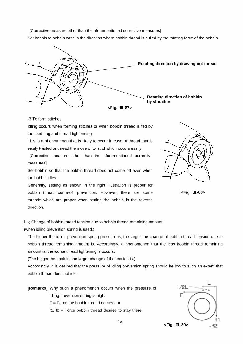
[Corrective measure other than the aforementioned corrective measures]
Set bobbin to bobbin case in the direction where bobbin thread is pulled by the rotating force of the bobbin.
-3 To form stitches
Idling occurs when forming stitches or when bobbin thread is fed by
the feed dog and thread tightenning.
This is a phenomenon that is likely to occur in case of thread that is
easily twisted or thread the move of twist of which occurs easily.
[Corrective measure other than the aforementioned corrective
measures]
Set bobbin so that the bobbin thread does not come off even when
the bobbin idles.
Generally, setting as shown in the right illustration is proper for
bobbin thread come-off prevention. However, there are some
threads which are proper when setting the bobbin in the reverse
direction.
③ Change of bobbin thread tension due to bobbin thread remaining amount
(when idling prevention spring is used.)
The higher the idling prevention spring pressure is, the larger the change of bobbin thread tension due to
bobbin thread remaining amount is. Accordingly, a phenomenon that the less bobbin thread remaining
amount is, the worse thread tightening is occurs.
(The bigger the hook is, the larger change of the tension is.)
Accordingly, it is desired that the pressure of idling prevention spring should be low to such an extent that
bobbin thread does not idle.
[Remarks] Why such a phenomenon occurs when the pressure of
idling prevention spring is high.
F = Force the bobbin thread comes out
f1, f2 = Force bobbin thread desires to stay there
<Fig. ⅢⅢⅢⅢ-88>
<Fig. ⅢⅢⅢⅢ-89>
Rotating direction by drawing out thread
<Fig. ⅢⅢⅢⅢ-87>
46
(Pressure of idling prevention spring)
L = Distance from the center when bobbin thread is fully wound
1/2 L = 1/2 distance of L
F > f1 x L ... ①
The above force is necessary when bobbin thread comes out from bobbin.
And, if the sewing continues, the bobbin thread remaining amount continues to decrease.
Even when the bobbin thread remaining amount reaches 1/2 L, the force,
F > f2 x 1/2 L .... ②
is necessary. In addition,
f1 x l = f2 x 1/2 L ... ③
is formed even the same bobbin since the same sewing is being performed. Accordingly, a formula,
F > f1 x L = f2 x 1/2 L
is introduced from ①, ② and ③.
If f1 = 1 g (pressure of idling prevention spring = 1 g), f2 = 2 g.
The difference is 1 g (2 g - 1 g = 1 g). However, if f1 = 10 g (pressure of idling prevention spring =
10 g), f2 becomes 20 g, the difference is 10 g (20 g - 10 g = 10 g).
The difference of 10 g is not much for the thick thread heavey-weight material sewing. However, for
the thin thread light-weight material sewing, sewing quality differentiates.
<<Conclusion>>
When considering the sewing stability, the ideal is sewing without idling prevention spring. However, the
idling prevention spring is absolutely necessary to prevent sewing from trouble due to bobbin thread idling.
It is needless to say that thorough control of spring pressure is necessary to protect demerit due to the idling
prevention spring.
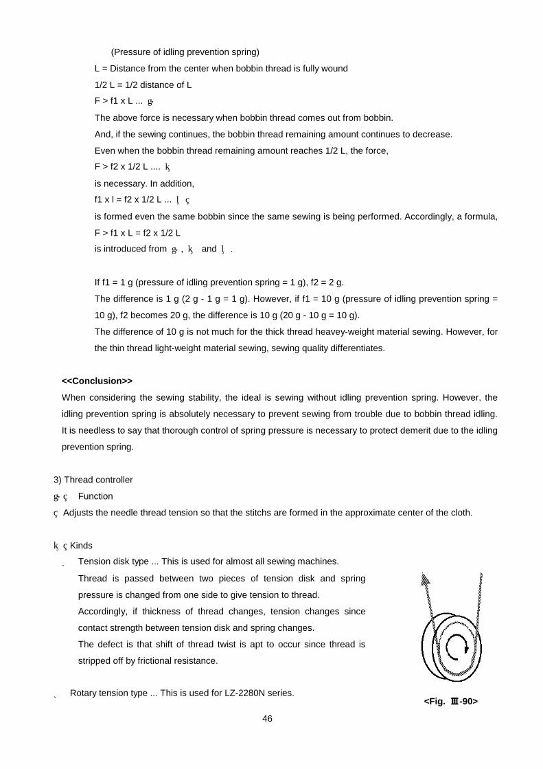
3) Thread controller
① Function
Adjusts the needle thread tension so that the stitchs are formed in the approximate center of the cloth.
② Kinds
* Tension disk type ... This is used for almost all sewing machines.
Thread is passed between two pieces of tension disk and spring
pressure is changed from one side to give tension to thread.
Accordingly, if thickness of thread changes, tension changes since
contact strength between tension disk and spring changes.
The defect is that shift of thread twist is apt to occur since thread is
stripped off by frictional resistance.
* Rotary tension type ... This is used for LZ-2280N series. <Fig. ⅢⅢⅢⅢ-90>

47
Position of tension nut (turn) 0 1 2 3 4 5 6 7 8 9 10
Type A:D3129-555-D00 90g 15 30 40 55 75 85 105 120 150 190 Tetoron
#80 Standard:B3129-012-A00 10g 24 48 75 105 120 150 180 240 - -
Type A:D3129-555-D00 12g 15 25 40 50 65 80 100 120 145 190 Spun #80
Standard:B3129-012-A00 12g 22 45 65 85 110 135 160 210 - -
This type winds thread one turn around roller, gives spring pressure from
one direction and gives tension to thread by frictional torque of spring
pressure and roller.
Change of tension due to thickness of thread is small, and thread can be
supplied under stable tension. Further, shift of thread twist due to
frictional resistance is small.
The defect is that when this type is compared with the thread tension
disk type, thread is apt to come off from roller and difficult to be passed.
Readjustment of tension may be necessary in accordance with the
change of thickness of thread.
* 1st tension (thread guide post) ... (Part No. : D1113-126-WA0))
This is effective for prevenstion of thread fluctuation, irregular stitch and balloon stitch.
Especially, effect appears for sewing under low tension of thin thread.
③ Relation between tightening position of tension nut and tension <Table ⅢⅢⅢⅢ-11>
Regard as "0" the place where end face
of tension nut on this side is aligned with
end of tension post.
Regard tightening of 1 turn as "1", and
that of 2 turns as "2".
<Fig. ⅢⅢⅢⅢ-91>
<Fig. ⅢⅢⅢⅢ-92>
1 turn
2 turns

48
① Function
This spring gives elasticity between hook and thread, and absorbs the resistance force at point A where a
large resistance is applied to thread. At this time, the motion of thread take-up spring works such a shape
as B. Thread supply amount (slack) of thread take-up lever is absorbed as much as amount C by the thread
take-up spring.
② Motion
The spring moves a little as B at point A (when hook pulls in needle thread at its maximum.) and moves to
its maximum stroke as D at the upper dead point of thread take-up lever (when thread take-up lever is lifted
to its maximum.).
③ Presser bar thread guide
This is connected to presser bar and moves up or down in
accordance with up/down motion of feed dog and change of
thickness of cloth to change the stroke of thread take-up
spring.
When cloth gets thicker, presser bar thread guide goes up and
stroke of thread take-up spring automatically becomes smaller.
<Fig. ⅢⅢⅢⅢ-93>
Curve of thread supply of threadtake-up lever
Curve of needle bar motion
Curve of hook thread take-up
Curve of thread take-up spring
Upper dead point of thread take-up lever
・ State of thread take-up spring at the time of E
(Thread absorption state)
・ State of thread take-up spring at the time of D
(Thread supply state)
Needle thread Needle thread
<Fig. ⅢⅢⅢⅢ-95> <Fig. ⅢⅢⅢⅢ-94>
Presser bar thread guide <Fig. ⅢⅢⅢⅢ-96>
Thread take-up spring
Stroke *
* Thread breakage prevention at overlapped section
4) Thread take-up spring

49

50
5) Needle bar thread guide
① Standard <Fig. ⅢⅢⅢⅢ-97> ... (Part No. : 110-05303)
This thread guide decreases thread fluctuation around needle tip, and is suitable
for the feed pitch 3 mm or less with thin synthetic thread.
This guide may be the resistance when performing thread tightening by thread
take-up lever at the time of thick thread and large feed pitch.
② For thick thread and large feed pitch (H type) <Fig. ⅢⅢⅢⅢ-98> ...
(Part No. : B1418-415-H00)
Thread hole protrudes to this side and when using this guide, resistance is small
at the time of thick thread and large feed pitch. In addition, thread tightening is
improved.
③ For extra thick thread <Fig. ⅢⅢⅢⅢ-99> ... (Part No. : 114-01619)
Thread hole protrudes to this side further than the aforementioned ②. This guide
is suitable for extra thick thread and feed pitch 5 mm or more.
④ For uneven stitch prevention <Fig. ⅢⅢⅢⅢ-100> ... (Part No. : B1418-227-T00)
This guide makes needle thread approach the needle as near as possible and
stability of thread is good. Also, this guide is good for thread breakage prevention
at the time of needle bent, uneven stitch, reverse feed stitching and idle stitching,
and is suitable for synthetic thread and thin thread. However, threading is rather
difficult and thread tightening is deteriorated with thick thread.
6) Needle thread tension disk (weak spring or felt)
① Function ... Prevention of thread fluctuation at needle portion
・ Prevention of piercing thread at needle tip
・ Prevention of bite to hook (thread tension in terms of blade point of hook is
increased.)
・ Prevention of stitch skipping (when blade point of hook scoops needle
thread, this disk gives resistance to thread to easily form loop. ... it is
effective for idle stitching or drop stitching.)
* Set the tension to 3 to 5 g since thread tightening by thread take-up lever is
deteriorated
7) Threading
Pass thread properly as described in the Instruction Manual. And, set
vertically "spool rest" and "spool pin".
Unevenness of thread tension occurs, resulting in irregular stitch or
thread breakage.
<Fig. ⅢⅢⅢⅢ-98>
<Fig. ⅢⅢⅢⅢ-102>
<Fig. ⅢⅢⅢⅢ-103>
<Fig. ⅢⅢⅢⅢ-97>
<Fig. ⅢⅢⅢⅢ-99>
<Fig. ⅢⅢⅢⅢ-100>
<Fig. ⅢⅢⅢⅢ-101>
Needle thread tension disk

50
Cloth
Uneven stitch Uneven stitch
Uneven stitch
Lower face irregular stitch
Upper cloth
Lower cloth
Stitch Upper face irregular stitch
Stitch Upper cloth
Lower cloth
Upper cloth
Lower cloth
Stitch
Stitch Stitch Stitch skipping skipping skipping
Upper cloth
Lower cloth
Uppercloth
Lower cloth
Needle thread
Bobbin thread breakage
Stitch
Cloth
Cloth
Slipping seam Stitch
Missing
Lower balloon stitch
ⅣⅣⅣⅣ) Defects of sewing that occur in sewing process and definition of terms
<Table ⅣⅣⅣⅣ-1>
No Term Definition (contents) Contents of defect
1
Uneven stitch
Stitching is not performed
straight and a part of stitches is
sewn in disorder.
2
Irregular stitch
Irregular knotting points of thread
occur on upper and lower faces
of cloths under a certain
tightness
3
Balloon stitch
Large or small thread loop
suddenly occurs on upper or
lower cloth from knotting point of
sewing thread.
4
Stitch skipping
Stitches of sewing thread
partially skip and stitching is not
performed completely.
5
Missing stitch
Stitches are out of the sewing
line.
6
Slipping seam
(slipping)
(slip-out)
When the force is applied to
stitch, the constituent thread of
the part moves and stitch opens
or slips.
7
Thread breakage
When the force is applied to
stitch, sewing thread is cut.

51
No Term Definition (contents) Contents of defect
8
Broken material Constituent threads of cloth are
cut by sewing machine needle at
the time of sewing.
9
Thread return
(Reverse)
The line that occurs when
constituent thread of cloth turns
and thread on the wrong side
faces the right side by the shock
force at the time of penetration of
sewing machine needle.
10
Weaving thread lift The state that defective gloss or
defective pattern occurs when a
part of weaving threads is shifted
by stitch, sewing machine
needle, awl, etc.
11
Seam puckering
(Small puckering)
(Small shrinkage)
Wrinkle that occurs near stitches
by shrinking by sewing, sewing
slippage, etc.
12
Sewing slippage
(Uneven material
feed)
Upper and lower cloths slip each
other in the feeding direction.
13
Left-to-right inclined
stitch of bobbin
thread
Left-to-right inclined stitches are
formed.
14
Seam grinning Stitch opens since tension of
sewing thread is insufficient.
Cloth
Stitch
Broken material
Cloth Thread return
Turn of constituent thread
Dense color
Thread return
Needle
Stitch
Cloth
Thread lift
Thread lift Stitch
Weaving thread
Sewing wrinkle (wavy condition)
* Cloth shrinks and becomes wavy.
Start of sewing
Upper cloth
Lower cloth
Stitch
End of sewing
Sewing slippage (Uneven material feed)
Cloth Stitch
Upper cloth Lower cloth
Grinning

52
No Term Definition (contents) Contents of defect
15
Towel face Knotting positions of sewing thread
continuously occur on the lower side of
cloth in the state of large thread rings.
16
Clogged stitch A certain resistance force is applied to
the sewing product and stitch pitch
becomes irregular.
17
Pitch error Stitch length is changed by change of
feed force, cloth slippage, etc. This
phenomenon is apt to occur between
high and low speed sewings.
18 Seam bray
(Thread
looseness)
Sewing thread gets loose and the state
of stitch skipping occurs.
19
Hangnail The state that several pieces of yarn of
sewing thread are cut during sewing.
20
Idle stitching
(Drop stitching)
Knotting point of thread is formed
without sewing product.
21
Feed dog defect
(Rasp-cut defect)
Scratch (trace of teeth) made by feed
dog when feeding cloth.
22
Needle breakage
defect
Scratch on sewing product made by
needle tip when several stitches are
performed in the state that needle is
broken during sewing.
23
Needle mark (Trace
of needle))
Trace of hole of sewing machine needle
due to re-sewing, basting, etc.
Upper cloth
Lower cloth
Towel face
Stitch Upper cloth Lower cloth
Clogged stitch Clogged stitch
Cloth Pitch error Pitch error
Stitch
Seam bray
Cloth
Seam bray
Needle thread
Bobbin thread
Hangnail
Upper cloth Lower cloth
Needle thread
Bobbin thread
Upper cloth Lower cloth
Idle stitching
Wrong side of cloth
Feed dog defect
Bobbin thread
Needle breakage defect
Needle thread
Needle tip breakage
Needle
Cloth
Needle mark
Upper cloth
Lower cloth

53
ⅤⅤⅤⅤ) Adjustment procedure
1. Bobbin thread tension
To properly operate the sewing machine, it is important that needle and bobbin thread tensions should be well
balanced. Generally, it seems that bobbin thread tension is not so carefully adjusted as needle thread
tension. Comparng with needle thread tension, bobbin thread tension is lower and fine adjustment for the
tension is necessary.
1) Adjustment procedure <Fig. ⅤⅤⅤⅤ-1>
Adjust the tension by tightening the screw in bobbin case. Slight moving of the screw only makes the tension
change greatly.
Turning the screw in the direction A increases the tension, and turning in the direction B decreases the
tension. 2) How to measure the tension <Fig. ⅤⅤⅤⅤ-2>
Measure the tension when slowly drawing out thread from bobbin case using the sector tension gauge or the
dial tension gauge (market-available).
<Fig. ⅤⅤⅤⅤ-1>
<Fig. ⅤⅤⅤⅤ-2>
Advice :
When using the bobbin case with idling prevention spring, there is no meaning even if measuring the tension in the state that the bobbin case is taken out from the hook.
In this case, set the bobbin case to the hook, draw out bobbin thread from the throat plate and measure
the tension while pulling out the thread in the slant direction to this side. <Fig. ⅤⅤⅤⅤ-2>

54
2. Needle thread tension
1) Adjustment procedure <Fig. ⅤⅤⅤⅤ-3>
Perform the adjustment using the thread adjustment nut. Turning the nut in the direction A increases the
tension and turning in the direction B decreases the tension.
When performing the adjustment, it is important to balance the tensions of needle and bobbin threads.
Adjust the needle thread tension to the bobbin thread tension after adjusting the bobbin thread tension. 2) How to measure the tension <Fig. ⅤⅤⅤⅤ-4>
Measure the tension in front of the thread take-up lever using the sector tension gauge or the dial tension
gauge.
3. Presser foot pressure
Height of the presser spring regulator which is called "chimney" is generally referred to the presser foot
pressure. However, even when the presser foot pressure is the same, the height of this regulator will change
in accordance with the kind of presser foot or presser spring.
1) Adjustment procedure
Loosen nut ② of presser spring regulator ① shown in <Fig. ⅤⅤⅤⅤ-5> and screw in screw ① in the direction
A to increase the presser foot pressure. To decrease the pressure to 1 to 3 kg, replace the presser spring
with the following ones.
For light-weight materials : B1505-227-T00A
For extra light-weight materials : 111-62104
For NF : 111-05202
2) How to measure the pressure Measure the height to adjust the pressure using the slide calipers or the scale. <Fig. ⅤⅤⅤⅤ-6>
<Fig. ⅤⅤⅤⅤ-3> <Fig. ⅤⅤⅤⅤ-4>
<Fig. ⅤⅤⅤⅤ-5>
<Fig. ⅤⅤⅤⅤ-6>
Thread tension
nut

55
・ Presser foot pressure measuring jig <Fig. ⅤⅤⅤⅤ-7>
Hook a market-available spring balancer to the string in the top end and
slowly lift it.
Double of the value when the top of the presser foot leaves from the
throat plate is the presser foot pressure.
4. Thread take-up spring
The basic adjustment of the lockstitch sewing machine is performed in the three places of the
aforementioned bobbin thread, needle thread and presser foot pressure. However, the part to be confirmed
next is the thread take-up spring <Fig. ⅤⅤⅤⅤ-8>.
A problem occurs when the thread take-up spring functions excessively or does not function.
1) How to adjust the stroke (thread absorption amount)
Slightly loosen setscrew ② shown in <Fig. ⅤⅤⅤⅤ-8>, turn tension
post ③ in the direction A to increase the stroke and turn it in the
direction B to decrease the stroke.
2) How to measure <Fig. ⅤⅤⅤⅤ-9>
Measure the moving amount of needle thread with a ruler or the like when the needle thread is drawn out to
the maximum from the presser bar thread guide. Fix the needle thread in front of the tension disk and
measure the stroke in the state that the presser foot is lowered and the feed dog is sunk.
3) How to adjust the tension
Adjust the tension with tension post ③ located in the center of needle thread tension nut <Fig. ⅤⅤⅤⅤ-8>. Turn
the tension post in the direction A to increase the tension and turn it in the direction B to decrease the
tension.
4) How to measure <Fig. ⅤⅤⅤⅤ-10>
Press and draw out the needle thread from presser bar thread guide and measure the tension when the
thread take-up spring moves by approximately 1 mm.
<Fig. ⅤⅤⅤⅤ-7>
<Fig. ⅤⅤⅤⅤ-9> <Fig. ⅤⅤⅤⅤ-10>
<Fig. ⅤⅤⅤⅤ-8>
Thread take-up
i

56
ⅥⅥⅥⅥ) Knowledge of the sewing thread
1. Construction and manufacturing process of the sewing thread
Natural textile products such as cotton thread, silk thread, etc. have been used as sewing thread before.
Nowadays, however, chemical fiber products such as polyester thread, nylon thread, etc. are largely used.
Filament thread, spun thread, woolly thread, mono-filament thread, etc. are properly used in accordance with
materials or applications. These threads are different from one another in construction and manufacturing
process as given below.
Filament thread means that left twist (Z twist) is applied to the thread after right twist (S twist) is applied to
the filament (long fiber) that is spun by melting and doubling of 2 to 3 filaments is performed.
Spun thread means that left twist (Z twist) (second twist) is applied to the staple (short fiber) after doubling
(first twist) of right twisted single yarn and doubling of 2 to 3 yarns is performed.
Filament yarn is performed the first twist and the twist is returned after superheating setting in the state that
the yarn is strongly pulled.
Wooly thread is a thread that doubling of these two yarns is performed and the twist is applied. This thread is
called filament expansion processed thread.
Spun thread (cotton thread, synthetic spun thread)
Filament thread
Wooly thread
<Fig. ⅥⅥⅥⅥ-1>
Long fiber that is spun by melting
Spinning (first twist)
Single yarn ・・・・ S twist
Doubling ・・・・ Twist (second twist)
Triple ply ・・・・ Z twist
<Fig. ⅥⅥⅥⅥ-2>
Twist (first twist)
Single yarn ・・・・ S twist
Doubling ・・・・ twist (second twist)
Triple ply ・・・・ Z twist
<Fig. ⅥⅥⅥⅥ-3>
Long fiber that is spun by melting
Single yarn ・・・・ S twist (first twist), heat set
Single yarn ・・・・ Z twist (first twist), heat set
Untwisting
Doubling ・・・・ twist (second twist)
Two-plied yarn ・・・・ Z twist
Untwisting
Short fiber such as cotton and syntheticfiber ( Synthetic fiber means that thelong fiber that is spun by melting is cutinto the short fiber. )
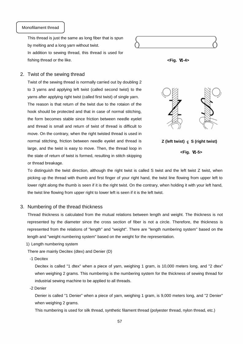
57
This thread is just the same as long fiber that is spun
by melting and a long yarn without twist.
In addition to sewing thread, this thread is used for
fishing thread or the like.
2. Twist of the sewing thread
Twist of the sewing thread is normally carried out by doubling 2
to 3 yarns and applying left twist (called second twist) to the
yarns after applying right twist (called first twist) of single yarn.
The reason is that return of the twist due to the rotaion of the
hook should be protected and that in case of normal stitching,
the form becomes stable since friction between needle eyelet
and thread is small and return of twist of thread is difficult to
move. On the contrary, when the right twisted thread is used in
normal stitching, friction between needle eyelet and thread is
large, and the twist is easy to move. Then, the thread loop in
the state of return of twist is formed, resulting in stitch skipping
or thread breakage.
To distinguish the twist direction, although the right twist is called S twist and the left twist Z twist, when
picking up the thread with thumb and first finger of your right hand, the twist line flowing from upper left to
lower right along the thumb is seen if it is the right twist. On the contrary, when holding it with your left hand,
the twist line flowing from upper right to lower left is seen if it is the left twist.
3. Numbering of the thread thickness
Thread thickness is calculated from the mutual relations between length and weight. The thickness is not
represented by the diameter since the cross section of fiber is not a circle. Therefore, the thickness is
represented from the relations of "length" and "weight". There are "length numbering system" based on the
length and "weight numbering system" based on the weight for the representation.
1) Length numbering system
There are mainly Decitex (dtex) and Denier (D)
-1 Decitex
Decitex is called "1 dtex" when a piece of yarn, weighing 1 gram, is 10,000 meters long, and "2 dtex"
when weighing 2 grams. This numbering is the numbering system for the thickness of sewing thread for
industrial sewing machine to be applied to all threads.
-2 Denier
Denier is called "1 Denier" when a piece of yarn, weighing 1 gram, is 9,000 meters long, and "2 Denier"
when weighing 2 grams.
This numbering is used for silk thread, synthetic filament thread (polyester thread, nylon thread, etc.)
<Fig. ⅥⅥⅥⅥ-4>
<Fig. ⅥⅥⅥⅥ-5>
Z (left twist) S (right twist)
Monofilament thread

58
2) Weight numbering system
There are mainly metric number, English number, etc.
-1 Metric number
Metric number is called "Nm 1" when a piece of thread, weighing 1,000 grams, is 1,000 meters long, and
"Nm 2" when the thread is 2,000 meters long. This numbering is used for worsted and woolen yarn.
-2 English number for cotton
English number for cotton is called "Ne 1" when a piece of thread, weighing 1 pound (453.6 g), is 840
(768.1 m) yards long, and "Ne 2" when the thread is 1,680 yards long. The thickness of cotton single yarn
is represented by English numbering. This numbering is used for cotton thread, silk spinning and staple
fiber.
3) Nominal count (thread count)
For "nominal count" (thread count) of the respective filament thread and spinning thread, the nominal count
that can be used in JIS (Japanese Industrial Standard) and the range of total size are normalized. Filament
thread and spinning thread are different in the total size although "nominal count" is the same. So, be
careful.
-1 Conversion table of sewing thread count
Filament <Table ⅥⅥⅥⅥ-1>
Nominal
count
(Thread
count)
Construction Total size of thread used
dtex (D)
Nominal
count
(Thread
count)
Construction Total size of thread used
dtex (D)
#1 3 x 3 2100 to 2520(1890 to 2250) #40 1 x 3 300 to 370(270 to 330)
#3 2 x 3 1750 to 2000(1575 to 1800) #50 1 x 3 220 to 267(200 to 240)
#5 2 x 3 1400 to 1700(1260 to 1500) #60 1 x 3 155 to 190(140 to 170)
#6 2 x 3 1167 to 1333(1050 to 1200) #80 1 x 3 117 to 150(105 to 135)
#8 2 x 3 978 to 1100(880 to 1000) #100 1 x 3 99 to 112(90 to 100)
#10 2 x 3 822 to 955(740 to 860) #120 1 x 2 78 to 90(70 to 80)
#20 2 x 3 660 to 801(600 to 720) #140 1 x 2 56 to 66(50 to 60)
#30 1 x 3 440 to 534(400 to 480) #150 1 x 2 44 to 50(40 to 45)
* For the indication method of the thickness of sewing thread for industrial sewing machine, indication
of "Decitex" and "Nominal count" is compulsory.

59
4. Melting point and softening point (゚C) of sewing thread
Both points are the indication of thermal resistance. Melting point means the temperature that sewing thread melts by
heat. Softening point means the temperature that the thread starts softening by heat. Especially, in case of synthetic
thread, stitch skipping or thread breakage occurs according to the circumstances. Accordingly, the thermal resistance
is one of the important points. In addition, the thermal resistance affects the temperature setting of iron and press in the
rear process. It is necessary to select a proper sewing thread after considering these factors.
5. Strength and ductility of the sewing thread
The force that is required to cut sewing thread by applying a load to the sewing thread in a certain direction
is called "strength". Percentage of elongation at this time is called "ductility".
Both the strength and the ductility are essential basic quality of sewing thread. For example, as to the
strength, when sewing heavy-weight materials, it is necessary to sew with sewing thread having high
strength since thread breakage is apt to occur. It is the same in case of preventing thread breakage or
puncture when wearing the clothes. As to the ductility, if it is excessive, it will be the cause of seam
puckering or stitch skipping, and if it is too low, it may be the cause of thread breakage.
In addition, when wearing clothes, thread breakage may occur unless there is the proper ductility.Both
strength and ductility depend on material, processing method and count of sewing thread. Accordingly, it is
necessary to select a proper sewing thread after considering sewing conditions, application of sewing
products, etc. Normally, when the strength and the ductility are simply used, they mean "pull strength and
pull ductility". For other items, there are "hook strength and hook ductility" and "knotting strength and
knotting ductility".
Spinning thread <Table ⅥⅥⅥⅥ-2>
Nominal
count
(Thread
count)
Count of
original
thread
(dtex)
Number
of
doubling
threads
Total size Nominal
count
(Thread
count)
Count of
original
thread
(dtex)
Number
of
doubling
threads
Total size
# 8 20s(300) 4 1200dtex # 50 50s(120) 3 360dtex
# 20 20s(300) 3 900dtex # 60 60s(100) 3 300dtex
# 30 30s(200) 3 600dtex # 80 80s(74) 3 222dtex
# 40 40s(145) 3 435dtex # 100 64s(92) 2 184dtex
Melting point and softening point of general sewing thread <Table ⅥⅥⅥⅥ-3>
Polyester Nylon 6 Nylon 66 Vinilon Cotton
Melting point 255 to 260゚C 215 to 220゚C 250 to 260゚C Unknown Decomposed at
150゚C
Softening
point
238 to 240゚C 180゚C 230 to 235゚C 220 to 230゚C None
As to the cotton, temperature at which the carbonization starts is described.

60
Strength and ductility of the sewing thread (Strength conforms to JIS and ductility is shown low.)
<Table ⅥⅥⅥⅥ-4>
Polyester sewing thread Nylon sewing thread Kind No. Strength
Ductility Filament Spinning Filament Wooly
Cotton
sewing thread
gf 1010 1110 950 710 50
% 22 18 30 8
gf 850 110d (1x2)
High
ductility % 35
* The above figures slightly differ among the respective thread manufacturers. Use them as reference values

61
Reference data 1
Shank diameter : A = divided in the following three systems for the most part.
Overlock series DCx1, DCx27 ... 2.02 mm
Lockstitch series DAx1 ... 1.63 mm (#6 to #22)
DBx1 ... 1.63 mm (#6 to #18)
... 2.00 mm (#19 or more)
Special sewing machine series
such as straight buttonholing or the like DPx5 ... 2.00 mm
Reference data 2
測定位置は矢印の所で右図のように刻印してあります
SCHMETZ 110◎シュメッツミシン針の番手は全てメートル法(1/100)で表示しております。
diameterin mm Nm0.65mm×100=Nm650.90mm×100=Nm901.10mm×100=Nm1101.30mm×100=Nm1302.50mm×100=Nm250
* All needle sizes of SCHMETZ needle are described by the metric system (1/100).
Measuring position is engraved in the place of arrow mark as shown in the right
illustration.
Diameter
in mm Nm
0.65 mm x 100=Nm 65
0.90 mm x 100=Nm 90
1.10 mm x 100=Nm 110
1.30 mm x 100=Nm 130
2.50 mm x 100=Nm 250

62
Comparison of needle sizes
(This table is made according to DIN (German Industrial Standard.)
SCHMETZ Metric system indication Nm = needle size
Japan # = needle size
Other size
Special size needle
Columbia Lewis Merrow Reece Singer Union Special
Wilcox and Gibbs
Embroidery 81.88 292 332 339 459R
35 2 23 22 40 3 3 22 21 45 4 4 21 20 50 5 5 20 19 55 6 3/0 6 022 18 18
60 7 8
2/0 8 2/0 3/0 16 8 17
65 9 2 1/2 0 9 025 0 14 16
70 10 10 1 3/0 10 027 1 2/0 2/0 13 2/
0
10 15
75 11 1 10 3 11 029 12 14
80 12 1 1/2 15 12 2 2/0 12 032 2 0 0 11 0 12 13
85 13 2 20 13 1/2 10
90 14 2 1/2 25 3 1/2 14 3 0 14 036 3 1 1 9 1/
2
13 12
95 15 3 30 15 8 100 16 3 1/2 4 16 4 1 16 040 4 2 2 7 1 14 11
105 17 17 110 18 4 4 1/2 18 5 2 18 044 5 3 3 6 2 16 10
120 19 19 6 3 19 048 6 4 4 3 17 9
125 20 4 1/2 5 20 20 049
130 21 5 7 4 21 7 4 5 3 4 8 140 22 5 1/2 5 22 054 8 5 2 5 7
150 6 8 060 9 6 1 6
160 23 6 23 10 6 0 6 170 9 067 7 7
180 24 7 24 073 7
190 8 200 25 25 080 9 8
230 26 26 090 9
250 27 100
280 28 300 29 120
330 30
350 31 140
380 32 400 33 156
430 34 172
460 35 480 36 188

63
Reference data 3
Shape of needle tip
Cross-section Abbreviations Designation ORGAN
R SET normal round point R
SPI S SET RS acute round point SPI
SES L BALL FFG SIN R-K light ball point J
SUK M BALL FG SI R-KB medium ball point B
SKF H BALL G heavy ball point U
SKL speciaiball point
STU SET RT big rounded point
for sewing on buttons
BUT
LL,LLS TW , NTW twist point LL
LR,LRS RTW ,NRTW reverse twist point LR

64
Reference data 4
Kind of needle and applicable machine
Japanese System Schmetz Needle Interchangeable Needle System Remarks
DB x 1 DB x 1 DB x 95,287WH,16 x 257,1738,
16 x 95,16 x 231,SY2270
Common to DP x 5 and 134
(Nm 120 or more)
General lockstitch sewing machine
DB x K5 DB x K5 120 DBx1 for multi-head embroidery (thick needle eyelet)
DB-N20 1738KK Same as DB x 1, but shank is short.
DB x A20 1738A 287WH,16 x 95 Same as DB x 1, but thickness of shank is same as that of
#18 or less.
DA x 1 DA x 1 1128,88 x 1,88 x 9,SY1315 Lockstich sewing machine (for light-weight materials)
DP x 5(DP x 134) DP x 5
134(R)
797,135 x 5,DP x 7,SY1901 For buttonholing and zigzag sewing, For European type
lockstitch
DP x 17 DP x 17 135 x 17,SY3355 Lockstitch sewing machine for heavy-weight materials,
auto-belter, etc.
DC x 27 B-27 RIM27,MY1023,SY6120 Overlock machine (flat scarf)
DC x 1 DC x 1 DM x 1,81 x 1,SY1225 General overlock machine
DC x 3 DC x 3 SY8538 Leather glove round stitching, 2-needle overlock machine, etc.
TV x 64 B-64 SY7045 Double chainstitch machine
TQ x 1 TQ x 1 29-S,1985,175 x 1,175 x 5
TQ x 5
Button sewing
TQ x 7 TQ x 7(2091) 175 x 7,SY8728 Button sewing, Longer by 10 mm than TQ x 1
TF x 2 34LL 16 x 2NTW For leather (slant lens shaped point)
TF x 2LR 34LR 16 x 2NRTW,16 x 2RTW For leather (reverse slant lens shaped point)
DB x F2 1738LR 16 x 230 NRTW
Common to 134LR
(Nm120 or more)
For leather (reverse slant lens shaped point)
DD x 1 328 214 x 1,SY4950 For extra heavy-weight materials and leather
DI x 3 332 29 x 3,SY3741 Exclusive for shoes and bag
DN x 1 UY143GS MY1013,92 x 1,SY4261,
U0 x 143G,UY x 143GS
For bag
TV x 1 TV x 1 149 x 1,SY2774 Hemming, welt seam
TV x 7 TV x 7(149X7) SY2776 Hemming, welt seam, double chainstitch for medium- and
heavy-weight materials
UY x 128GAS UY x 128GAS 1280, UY128GSMY1044,DV x G9 Flat-bed 2/3-needle covering stitch machine
MT x 190 190(R) SY7555 Basting, pad closing, welting for Eagle and others

<<Reference books>> • HIROSE MFG., LTD. Technical manual • ORGAN NEEDLE CO., LTD. Sewing Q and A • Ditto Catalogue • FERD. SCHMETZ GMBH Needle catalogue • Bunka Fashion College Basic operation and knowledge of industrial sewing machine and iron • TOKYO ITODONYA ASSOCIATION Sewing thread handbook • JIS (Japanese Industrial Standard) Japan standard association • JUKI CORPORATION Manual on sewing thread, hook and needle • Ditto Basic knowledge of sewing machine
BASIC KNOWLEDGE OF SEWING DATE ISSUED : MARCH 20, 1999 FIRST PRINTING OF FIRST EDITION
EDITING : JUKI CORPORATION
SEWING CONSULTING DEPT.
PRODUCTION AND ISSUE : JUKI CORPORATION
SEWING RESEARCH INSTITUTE
KOKURYO-CHO, CHOFU-SHI, TOKYO 182-8655, JAPAN
PHONE : 03-3480-8500 FAX : 03-3480-7650
Copyright c 1999 JUKI CORPORATION
Reproduction or reprinting of the description covered in this book in part or whole without permission is forbidden.