
JUE-250 Installation Manual 7ZPSC0185 - wlnet.com · putting your free hand in your pocket, ......
67
JUE-250 Inmarsat FleetBroadband FB250 Maritime Satellite Communication Terminal Installation Manual 7ZPSC0258
Transcript of JUE-250 Installation Manual 7ZPSC0185 - wlnet.com · putting your free hand in your pocket, ......

JUE-250 Inmarsat FleetBroadband FB250
Maritime Satellite Communication Terminal
Installation Manual 7ZPSC0258


ABOUT YOUR SAFETY
CAUTIONS AGAINST HIGH VOLTAGE Radio and radar devices are operated by high voltages of anywhere from a few hundred volts up to many hundreds of thousands of volts. Although there is no danger with normal use, it is very dangerous if contact is made with the internal parts of these devices. (Only specialists should attempt any maintenance, checking or adjusting.) There is a very high risk of death by even a few thousand volts, in some cases you can be fatally electrocuted by just a few hundred volts. To circumvent accidents, you should avoid contact with the internal parts of these devices at all costs. If contact is inevitable as in the case of emergency, you must switch off the devices and ground a terminal in order to discharge the capacitors. After making certain that all the electricity is discharged, only then can you insert your hand into the device. Wearing cotton gloves and putting your free hand in your pocket, in order not to use both hands simultaneously, are also very good methods of shock prevention. Quite often, an injury occurs by secondary factors, therefore it is necessary to choose a sturdy and level working surface. If someone is electrocuted it is necessary to thoroughly disinfect the affected area and seek medical attention as soon as possible.
CAUTIONS CONCERNING TREATMENT OF ELECTROCUTION VICTIMS When you find an electrocution victim, you must first switch off the machinery and ground all circuits. If you are unable to cut off the machinery, move the victim away from it using a non-conductive material such as dry boards or clothing. When someone is electrocuted, and the electrical current reaches the breathing synapses of the central nervous system inside the brain, breathing stops. If the victim’s condition is stable, he or she can be administered artificial respiration. An electrocution victim becomes very pale, and their pulse can be very weak or even stop, consequently losing consciousness and becoming stiff. Administration of first aid is critical in this situation.

FIRST AID
☆Note points for first aid
Unless there is impending danger leave the victim where he or she is, then begin artificial respiration. Once you begin artificial respiration, you must continue without losing rhythm. (1) Make contacts with the victim cautiously, there is a risk that you may get electrocuted. (2) Switch off the machinery and then move the victim away slowly if you must. (3) Inform someone immediately (a hospital or doctor, dial emergency numbers, etc.). (4) Lay the victim on his or her back and loosen any constructive clothing (a tie, or belt). (5) (a) Check the victim’s pulse. (b) Check for a heartbeat by pressing your ear against the victim’s chest.
(c) Check if the victim is breathing by putting the back of your hand or face near the victim’s face. (d) Check the pupils of the eyes. (6) Open the victim’s mouse and remove any artificial dentifrice, food or chewing gum. Leave the mouth
opened and flatten the tongue with a towel or by putting something into the mouth to prevent the victim’s tongue from obstructing the throat (If he or she is clenching their teeth and it is difficult to open the mouth, use a spoon or the like to pry open the mouth).
(7) Continually wipe the mouth to prevent the accumulation of saliva.

☆ If the victim has a pulse but is not breathing
(“Mouth to mouth” resuscitation) Figure 1
(1)Place the victim’s head facing backward (place something under the neck like a pillow). (2)Point the chin upward to widen the trachea. (3)Pinch the victim’s nose, take a deep breath, then put your mouth over the victim’s mouth and exhale
completely, making sure that your mouth completely covers the victim’s mouth. Then remove your mouth. Repeat this routine 10 to 15 times per minute (holding the nostrils).
(4)Pinch the victim’s nose, take a deep breath, then put your mouth over the victim’s mouth and exhale completely, making sure that your mouth completely covers the victim’s mouth. Then remove your mouth. Repeat this routine 10 to 15 times per minute (holding the nostrils).
(5)Pay attention to the victim to notice if he or she starts to breath. If breathing returns, stop resuscitation. (6)If it is impossible to open the victim’s mouth, put something like a plastic straw or vinyl tube into one of
the nostrils then blow air in while covering the mouth and the other nostril. (7)Occasionally, when the victim comes back to consciousness, they immediately try to stand up. Prevent
this and keep them in a laying position. Give them something warm to drink and be sure that they rest (do not give them any alcohol).
Administering artificial respiration by raising the head. ① (1) Raise the back of head, then place one hand on
the forehead and place the other hand under the neck. →①
Most victims open their mouth when doing this, making “mouth to mouth” resuscitation easier.
② (2) Cover the victim’s mouth by opening your
mouth widely, then push your cheek against the victim’s nose, →② or pinch the victim’s nose to prevent air from leaking out of it. →③
③ (3) Completely exhale into the lungs. Exhale into the lungs until the chest is inflates.
You have to blow as rapidly as possible for the first 10 times.
“Mouse to mouse” artificial respiration
Figure 1
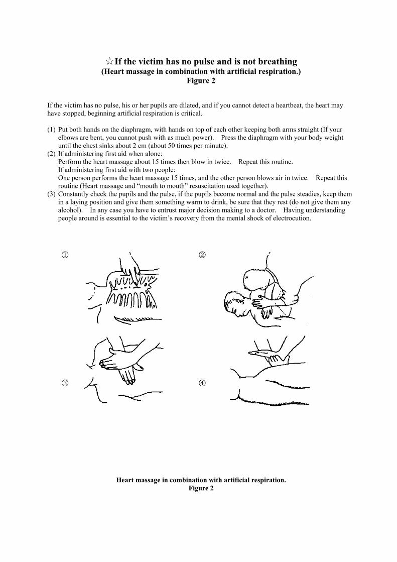
☆ If the victim has no pulse and is not breathing
(Heart massage in combination with artificial respiration.) Figure 2
If the victim has no pulse, his or her pupils are dilated, and if you cannot detect a heartbeat, the heart may have stopped, beginning artificial respiration is critical. (1) Put both hands on the diaphragm, with hands on top of each other keeping both arms straight (If your
elbows are bent, you cannot push with as much power). Press the diaphragm with your body weight until the chest sinks about 2 cm (about 50 times per minute).
(2) If administering first aid when alone: Perform the heart massage about 15 times then blow in twice. Repeat this routine. If administering first aid with two people: One person performs the heart massage 15 times, and the other person blows air in twice. Repeat this routine (Heart massage and “mouth to mouth” resuscitation used together).
(3) Constantly check the pupils and the pulse, if the pupils become normal and the pulse steadies, keep them in a laying position and give them something warm to drink, be sure that they rest (do not give them any alcohol). In any case you have to entrust major decision making to a doctor. Having understanding people around is essential to the victim’s recovery from the mental shock of electrocution.
① ② ③ ④
Heart massage in combination with artificial respiration. Figure 2

i
PREFACE Thank you for purchase of the JRC Inmarsat FleetBroadband Mobile Earth Station, JUE-250. The JUE-250 is an Inmarsat digital satellite communication terminal for Voice (4kbps Voice), and Audio
(64kbps 3.1kHz Audio), maximum 284kbps Standard IP service, 32kbps, 64kbps, or 128kbps Streaming IP
service, and Short Messaging Service (SMS).
• Please read this manual carefully and carry out proper installation. • Please keep this manual carefully to be able to refer to. Please read this manual when questions of use and troubles are caused by any chance.

ii
ATTENTIONS BEFORE INSTALLATION • JRC cannot accept responsibility for any loss due to incorrect operation, malfunction, and other causes
except product guarantee condition and liability by law.
• Some functions of JUE-250 may not work correctly owing to the hardware and software version of equipment connected to JUE-250. Please confirm to the dealer or agent you purchased, or JRC branches whether your equipment is connectable.
• Your communication data are transmitted via Inmarsat system and other global communications system, so some errors may occur in communication the same as the landlines. You are recommended to backup for your important data.
• Your communication data will be protected by digital scrambling of Inmarsat. However, you are recommended to understand that your communication data might be intercepted by special technology and unauthorized access .
• Specifications of JUE-250 and its accessories may change without notice for improvement.

iii
DANGER
BEFORE INSTALLATION Concerning the symbols
This manual uses the following symbols to explain the correct operation and to prevent injury or damage to property. Please read the following before proceeding with this manual.
Indicates danger that, if ignored, will result in serious injury or even death.
Indicates warning that, if ignored, may result in serious injury or even death. Indicates caution that, if ignored, may result in injury or damage to property.
Examples of symbols
The symbol indicates caution (including DANGER and WARNING). The illustration inside the symbol specifies the content of the caution more accurately. (This example warns of possible electrical shock.) The symbol indicates that performing an action is prohibited. The illustration inside the symbol specifies the content of the prohibited operation. (In this example disassembly is prohibited.) The ● symbol indicates operations that must be performed. The illustration inside the ● symbol specifies obligatory instructions. (In this example unplugging is obligatory.)
* Windows Internet Explorer is a registered trademark of Microsoft Corporation.
Netscape Navigator is a registered trademark of Netscape Communications Corporation.
WARNING
CAUTION

iv
Concerning warning label Warning labels are put on the JUE-250, ADE, and BDE. Do not take off, destroy, or modify these labels. <Warning Label of ADE > <Warning Label of BDE >
Notes
International Mobile Equipment Identity (IMEI) is a unique number used to identify an individual mobile equipment to a GSM or UMTS network.
Attestation number which means safe, high-quality product and suits EU instruction
(Free circulation was permitted in the EU signatory).
IMEI 35887701

v
WARNING
DANGER
CAUTIONS DURING INSTALLATION
Do not touch any internal parts with your hands or tools to avoid danger of electronic shock.
Do not touch master gyro signal lines with your hands to avoid danger of electrical shock. The lines always have high voltages even if your JUE-250 power switch is turned off.
CAUTIONS DURING INSTALLATION
Do not bring JUE-250 (ADE) close to the fire, or put it in the fire. It causes the explosion and electrical shock.
Do not approach the ADE while transmitting. Strong micro wave might be cause injury.
If an external matter, such as metal fragments, water, liquid, etc., infringe into your JUE-250, turn off the power and contact the dealer or agent you purchased from or one of our JRC branches. Continuous operation may cause fire, electrical shock or malfunction.
Install JUE-250 correctly in accordance with the installation manual. Inappropriate installation may cause incorrect operation; fire, electrical shock, or malfunction. JUE-250 should be installed by the trained technician or engineer. The installation should be requested to the purchasing dealer, JRC agent or one of the JRC branches.
Install JUE-250 ADE-BDE coaxial cable correctly in accordance with the installation manual of separate volume. Especially waterproof should be treated correctly in accordance with this manual. Inappropriate installation may cause incorrect operation, fire, electrical shock or malfunction. JUE-250 should be installed by the special technician or skilled engineer. The installation should be requested to the purchasing dealer, JRC agent or one of the JRC branches.
Do not turn on the terminal under the primary power except the specific voltage (+19VDC to +31VDC). The primary power except the specific voltage may cause fire, electrical shock or malfunction,
Do not fix or repair the internal equipment of the JUE-250 by yourself. Any person other than our trained maintenance staff may cause fire or abnormal operation of this equipment or electrical shock. This equipment meets the technical standard of the Ministry of Internal affairs and Communications.
Do not adjust the internal circuit or change the parts because the internal circuit is adjusted strictly. If an abnormal operation is found, please contact to out sales department or nearest branch office.
vi
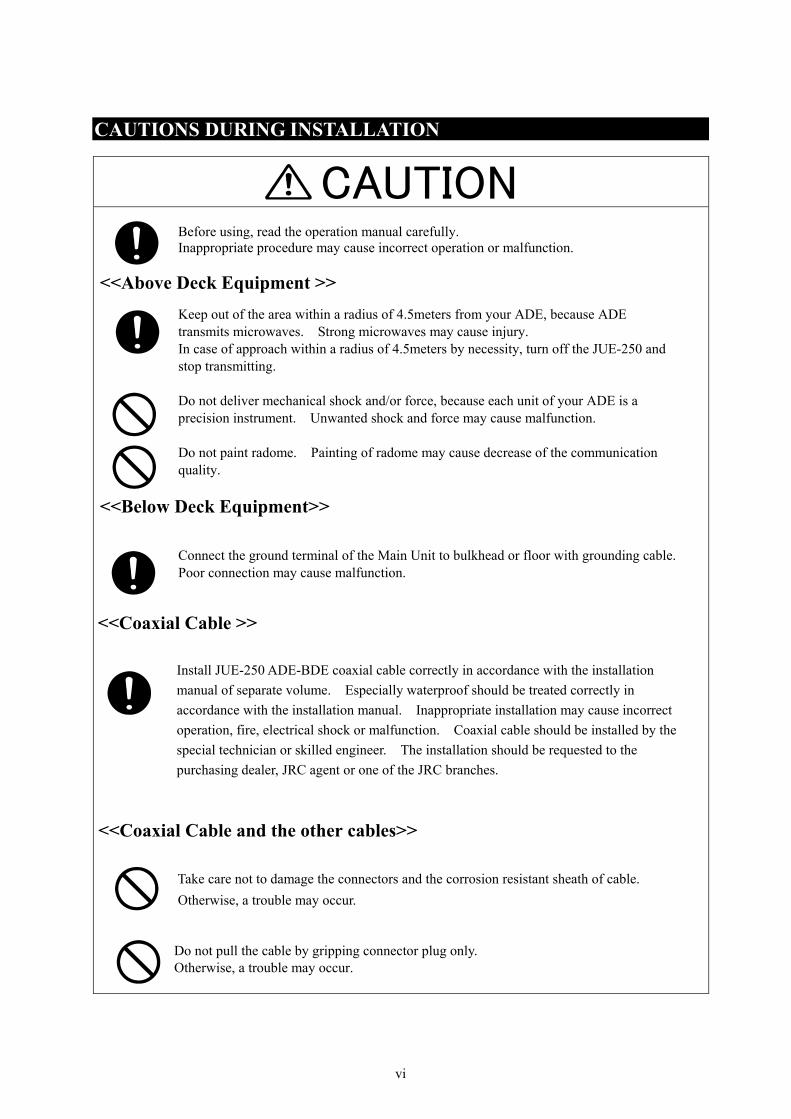
CAUTION
CAUTIONS DURING INSTALLATION
Before using, read the operation manual carefully. Inappropriate procedure may cause incorrect operation or malfunction.
<<Above Deck Equipment >> Keep out of the area within a radius of 4.5meters from your ADE, because ADE transmits microwaves. Strong microwaves may cause injury. In case of approach within a radius of 4.5meters by necessity, turn off the JUE-250 and stop transmitting. Do not deliver mechanical shock and/or force, because each unit of your ADE is a precision instrument. Unwanted shock and force may cause malfunction. Do not paint radome. Painting of radome may cause decrease of the communication quality.
<<Below Deck Equipment>> Connect the ground terminal of the Main Unit to bulkhead or floor with grounding cable. Poor connection may cause malfunction.
<<Coaxial Cable >>
Install JUE-250 ADE-BDE coaxial cable correctly in accordance with the installation manual of separate volume. Especially waterproof should be treated correctly in accordance with the installation manual. Inappropriate installation may cause incorrect operation, fire, electrical shock or malfunction. Coaxial cable should be installed by the special technician or skilled engineer. The installation should be requested to the purchasing dealer, JRC agent or one of the JRC branches.
<<Coaxial Cable and the other cables>>
Take care not to damage the connectors and the corrosion resistant sheath of cable. Otherwise, a trouble may occur.
Do not pull the cable by gripping connector plug only. Otherwise, a trouble may occur.

vii
APPEARANCE ADE (Above Deck Equipment) [GSC-451] The ADE is installed on the above deck for receiving the signal from the satellite. The ADE is covered with a radome.
Fig.1 ADE (inside of radome)
Fig.2 ADE appearance

viii
BDE (Below Deck Equipment) Main Unit [GSC-452]
The BDE is on the below deck and includes the transceiver.
Fig.3 Main unit Handset [NQW-267]
The Handset is used for voice communication, and is for controlling the terminal.
[Cable length:1m]
Fig.4 Handset
ix
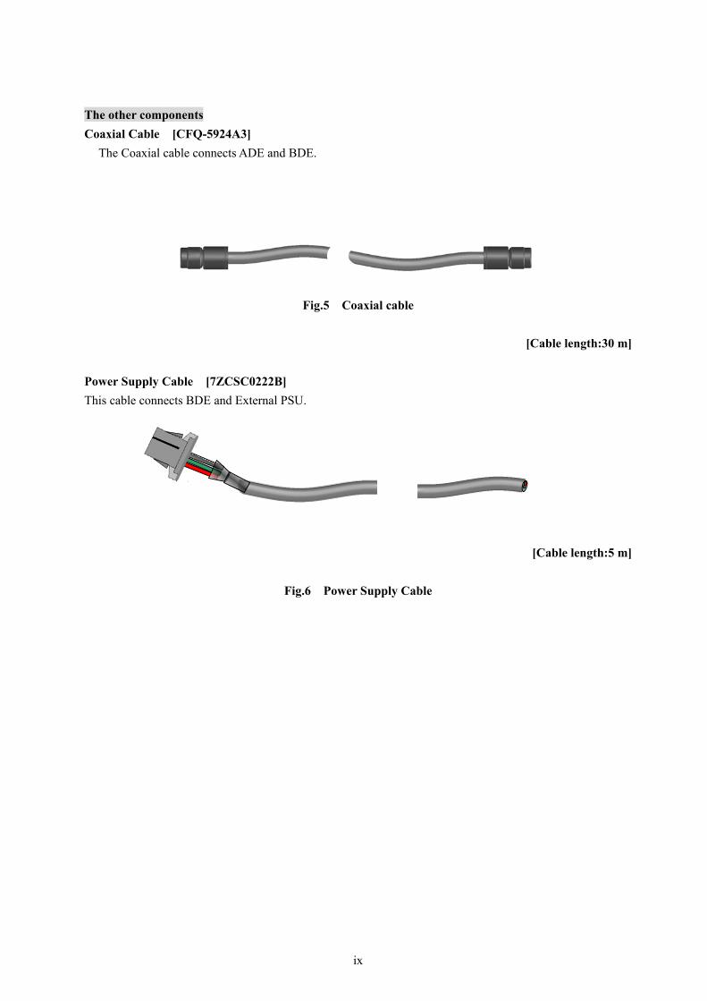
The other components Coaxial Cable [CFQ-5924A3]
The Coaxial cable connects ADE and BDE.
Fig.5 Coaxial cable
[Cable length:30 m] Power Supply Cable [7ZCSC0222B] This cable connects BDE and External PSU.
[Cable length:5 m]
Fig.6 Power Supply Cable

x
ABBREVIATIONS
ADE Above Deck Equipment
BDE Below deck Equipment
External PSU External Power Supply Unit
FWD Forward (bow)
INMARSAT INMARSAT Ltd.
JB Junction Box
MES Mobile Earth Station
TEL Telephone

Contents PREFACE........................................................................................................................................................i ATTENTIONS BEFORE INSTALLATION..................................................................................................ii BEFORE INSTALLATION ..........................................................................................................................iii CAUTIONS DURING INSTALLATION......................................................................................................v APPEARANCE............................................................................................................................................vii ABBREVIATIONS ........................................................................................................................................x
1. INTRODUCTION .....................................................................................................................................1-1 1-1 Outlines..............................................................................................................................................1-1 1-2 Unpacking and visual inspection .......................................................................................................1-1 1-3 Cable connection diagram..................................................................................................................1-2 1-4 Components .......................................................................................................................................1-3
1-4-1 JUE-250 Standard components ....................................................................................................1-3 1-4-2 Optional components..................................................................................................................1-3
1-5 Configuration (JUE-250 Standard components) ................................................................................1-4 1-5-1 ADE (Above Deck Equipment) [GSC-451] ...............................................................................1-4 1-5-2 BDE (Below Deck Equipment) [GSC-452] ...............................................................................1-5 1-5-3 Handset [NQW-267]...................................................................................................................1-6 1-5-4 Coaxial cable [CFQ-5924A3].......................................................................................................1-7
1-6 Installation parts and tools .................................................................................................................1-8 1-6-1 Supplied parts by JRC ................................................................................................................1-8 1-6-2 Required cables...........................................................................................................................1-8 1-6-3 Required tools.............................................................................................................................1-8
1-7 Configuration (Optional components) ...............................................................................................1-9 1-7-1 Telephone [NQW-132B] ............................................................................................................1-9 1-7-2 Facsimile [OKI OFFICE 86] ....................................................................................................1-11 1-7-3 EXT. PSU (External Power Supply Unit) [NBD-577C]...........................................................1-12 1-7-4 TEL JB (Telephone Junction Box) [NQE-3058B]....................................................................1-13 1-7-5 GYRO I/F Box [NQA-2066]....................................................................................................1-14 1-7-6 Power transformer for Facsimile [DD-118525]........................................................................1-15
2. INSTALLATION .......................................................................................................................................2-1 2-1 ADE ...................................................................................................................................................2-1
2-1-1 Plan of installation site................................................................................................................2-1 2-2 Design of Pole....................................................................................................................................2-2
2-2-1 Example of pole..........................................................................................................................2-2 2-2-2 Load specification and basic design. ..........................................................................................2-2
3. Installation work ........................................................................................................................................3-1 3-1 ADE ...................................................................................................................................................3-1
3-1-1 Installation Example1 (Pole installation to ADE fixing) ............................................................3-2 3-1-2 Installation Example2 (Pole installation to ADE fixing) ............................................................3-6
3-2 BDE Installation...............................................................................................................................3-10 3-2-1 Main Unit..................................................................................................................................3-10 3-2-2 Handset .....................................................................................................................................3-17

3-2-3 GYRO I/F BOX........................................................................................................................3-18 3-2-3 GYRO I/F setting......................................................................................................................3-22
3-3 Cable ................................................................................................................................................3-23 3-3-1 Cable routing ............................................................................................................................3-23 3-3-2 Connection to ADE...................................................................................................................3-23 3-3-3 Connection to BDE...................................................................................................................3-24 3-3-4 Connection to primary Power ...................................................................................................3-25 3-3-5 Abandonment work ..................................................................................................................3-25
4. SPECIFICATION ......................................................................................................................................4-1 4.1 JUE-250 Standard components ..........................................................................................................4-1
4.1.1 ADE and BDE ............................................................................................................................4-1 5. JRC Network .............................................................................................................................................5-1

1-1
1. INTRODUCTION
1-1 Outlines
The JUE-250 Mobile Earth Station (MES) is composed of Above Deck Equipment (ADE) and Below Deck Equipment (BDE).
The ADE consists of Antenna Assembly, Above Deck Unit and Radome, while the BDE consists of Main Unit (MU) and Handset.
1-2 Unpacking and visual inspection
At the time of unpacking, visual inspection should be made for any possible damage during transportation, and also check any missing part in accordance with supplied parts list for installation as shown in Table 1-6-1. If there is damage or missing part, file the claim immediately.
The components are shown in Section 1-4 and the configuration of the ADE and the BDE are shown in Section 1-5. Be careful to avoid the damage to unit attachment cable or terminals, when transporting or operating the JUE-250.
JUE-250 is a Inmarsat digital satellite communication terminal for 4kbps speech voice service, 9.6kbps G3 FAX, maximum 284bps Standard IP data service, 32kbps, 64kbps, or 128kbps Streaming IP data service and Short Messaging Service (SMS).
JUE-250 is shipped with strict quality control and inspection to provide the high quality for consumers. JRC would like to believe you to make long use of the terminal with your satisfaction.
If your JUE-250 has trouble or problem in your operation, please contact the dealer, agent or JRC branches you purchased.
If the contact place is unknown, please confirm on JRC website (refer to chapter 5).
1-2
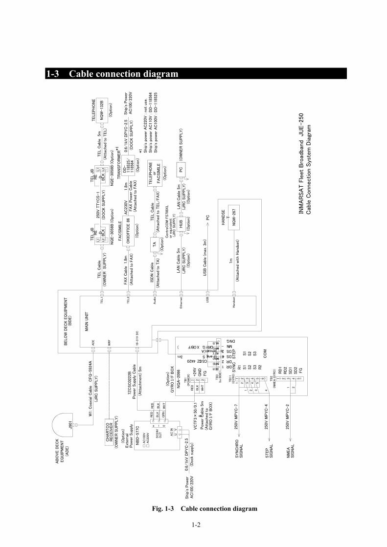
1-3 Cable connection diagram
Fig. 1-3 Cable connection diagram
J901
CFQ
-5924A
W1: C
oax
ial C
able
AD
E
TEL1
Eth
ern
et
AB
OV
E D
EC
K
EQ
UIP
MEN
T
(AD
E)
INM
AR
SA
T F
leet
Bro
adba
nd
JU
E-25
0C
able
Connection S
yste
m D
iagr
am
MA
IN U
NIT
WR
FC
HA
RTC
OR
EC
EIV
ER
(OW
NER
SU
PP
LY)
7ZC
SC
0222B
19-31V
DC
Ship
's P
ow
er
USB
Cab
le (m
ax. 3m
)P
C
(Att
ached
with H
ands
et)
TEL2
Audi
o
USB
Han
dset
RE D
BLK
L2
L1TEL J
B
NQ
E-3058B
250V
TTYC
S-1
RE D
BLK
L2
L1
TEL J
B
NQ
E-3058B
TEL C
able
5m
NQ
W-132B
TELEP
HO
NE
OKIO
FFIC
E 8
6
FA
CSIM
ILE
(Att
ache
d t
o F
AX)
FA
X C
able
1.
8m
TEL C
able
(OW
NER
SU
PP
LY)
ISD
N C
able
(Att
ached
to T
A)
LA
N C
able
5m
(JR
C S
UP
PLY)
PC
HU
B
Cent
reC
OM
FS708
XL
or
equi
vale
nt (
JR
C S
UP
PLY)
LA
N C
able
5m
(JR
C S
UP
PLY)
(OW
NER
SU
PP
LY)
1m
HA
ND
SE
T
(JR
C S
UP
PLY)
Pow
er
Suppl
y C
able
(Att
achm
ent)
5m
Ext
ernal
P
ow
er
Supp
ly
AC
100/220V
7ZCSC0244Signal Cable 3m
(Attached to GYRO I/F BOX)
TB
3(t
o B
DE)
RD1RD2SD1SD2NM-GND
12
34
56
TB
11
(GYR
O)
1 2 3 4 5 6
250V
MP
YC
-7
250V
MP
YC
-4
1 2 3 4
1 2 3 4
S1
S2
S3
CO
M
R1
S1
S2
S3
R2
STEP
SYN
CSYN
CH
RO
SIG
NA
L
STEP
SIG
NA
L
1 2 3 4 5
1 2
TB
2(N
MEA
GYR
O)
NM
EA
SIG
NA
L250V
MP
YC
-2
RD
1R
D2
SD
1
FG
SD
2
5
1 2 3
BLK
WH
T
TB
1(P
OW
ER
) +24V
GN
DFG
RED
VC
TF3×
50/0.1
8P
ow
er
Cab
le 5
m(A
ttac
hed
to
GYR
O I/F B
OX)
GYR
O I/F
BO
X
NQ
A-2066
RED
BLK
NB
D-577C + -
DC
24V
OU
TE
RED
BLK
WH
TG
RN
AC
100V
AC
220V AC
IN
UV
0.6
/1kV
DP
YC
-2. 5
(Dock
supply
)
AC
230V
TR
AN
SFO
RM
ER
Ship
's P
ow
er
AC
100/220V
(Att
ached t
o F
AX)
FA
X P
ow
er
Cab
le1.8
m
RED
BRN
ORN
YEL
GRN
BLU
(Opt
ion)
(Opt
ion)
(Opt
ion)
(Option)
(Option)
DD
-118525/
118564
(Opt
ion)
(Opt
ion)
(Opt
ion)
NQ
W-267
BELO
W D
EC
K E
QU
IPM
EN
T (B
DE)
(Opt
ion)
(Opt
ion)
TELEP
HO
NE
TA
TEL C
able
(Option)
(Att
ached t
o T
EL/FA
X)
FA
CSIM
ILE
or
0.6
/1kV
DP
YC
-2.5
(DO
CK S
UP
PLY)
*1
*1
Ship
's p
ow
er
AC
220V
: n
ot
use
.Ship
's p
ow
er
AC
110V
: D
D-118564
Ship
's p
ow
er
AC
100V
: D
D-118525
(DO
CK S
UP
PLY)
(Option)
(Att
ached
to T
EL)

1-3
1-4 Components 1-4-1 JUE-250 Standard components
Name of component Type Q’ty
ADE GSC-451 1
BDE GSC-452 1
Handset NQW-267 1
Coaxial cable CFQ-5924A3/CFQ5924A15* 1
PSU cable(PSU⇔BDE) 7ZCSC0222B 1
JUE-250 Operation manual 7ZPSC0256 1
JUE-250 Installation manual 7ZPSC0258 1
JUE-250 Quick Operation Guide 7ZPSC0260 1
JUE-250 CD-ROM 7YZSC0007 1
Inspection result 1
* The length of CFQ-5924A3 is 30m, and CFQ5924A15 is 15m. 1-4-2 Optional components
Name of component Type Q’ty
Telephone NQW-132B 1
Facsimile OKIOFFICE 86 1
Power transformer for Facsimile (100V to 230V) DD-118525 1
External PSU NBD-577C 1
TEL JB NQE-3058B 2
RS232 Cable(BDE to PC) 7ZCSC0196 1
GYRO I/F (Interface) Box NQA-2066 1
Terminal Adaptor MTA128ST 1
Table 1-4-1 JUE-250 Standard components
Table 1-4-2 Optional components

1-4
1-5 Configuration (JUE-250 Standard components) 1-5-1 ADE (Above Deck Equipment) [GSC-451]
Unit: mm Mass: Approx.7.4kg
Fig. 1-5-1 ADE

1-5
1-5-2 BDE (Below Deck Equipment) [GSC-452]
Unit: mm Mass: Approx. 2.2 kg
Fig. 1-5-2 BDE
1-6
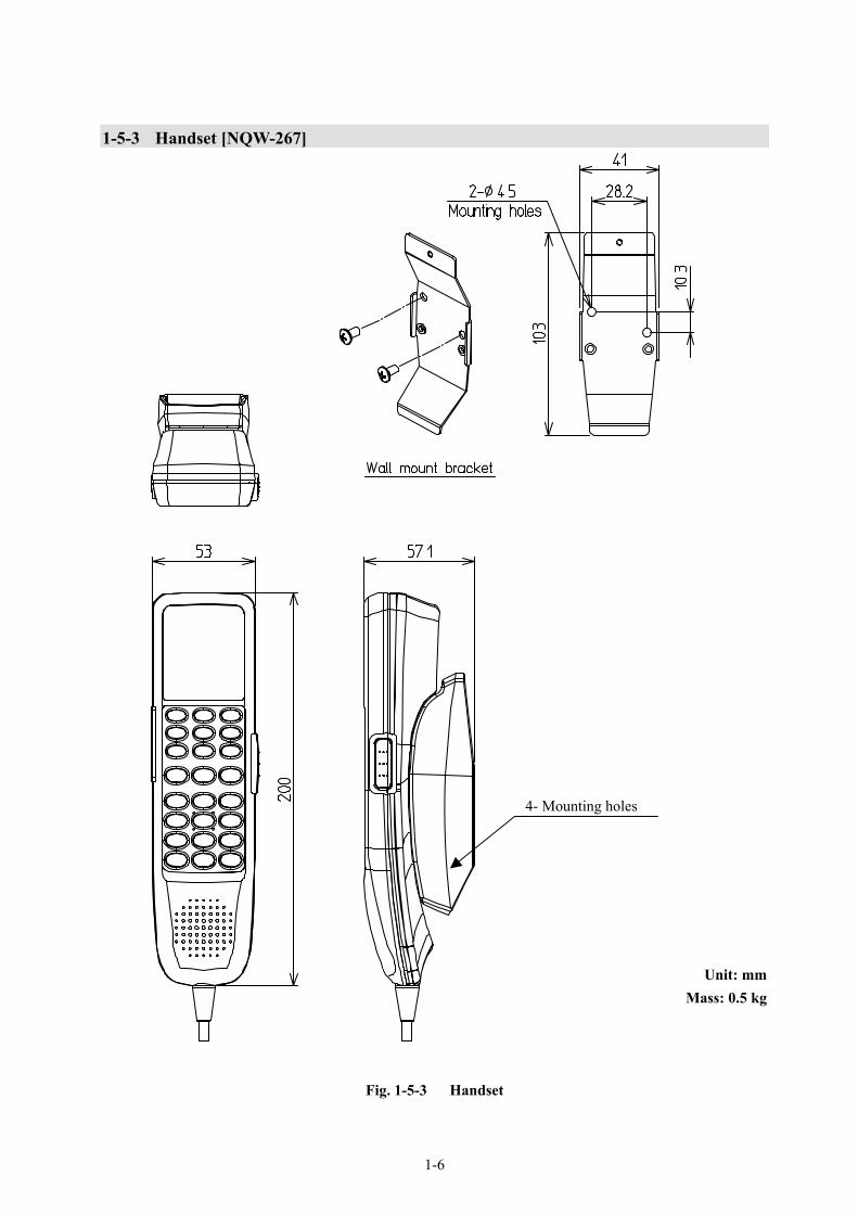
1-5-3 Handset [NQW-267]
Unit: mm Mass: 0.5 kg
Fig. 1-5-3 Handset
4- Mounting holes

1-7
1-5-4 Coaxial cable [CFQ-5924A3] mm
mm *CFQ5924A15 is available as optional component.
Minimum bending radius:46mm
Type Length Mass CFQ-5924A3 30m(±1.0m) Under2.3kg CFQ5924A15 15m(±0.5m) Under1.4kg
Fig. 1-5-4 Coaxial cable
Unit : mm
1-8
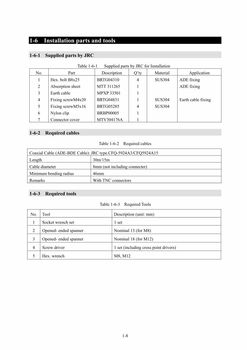
1-6 Installation parts and tools 1-6-1 Supplied parts by JRC
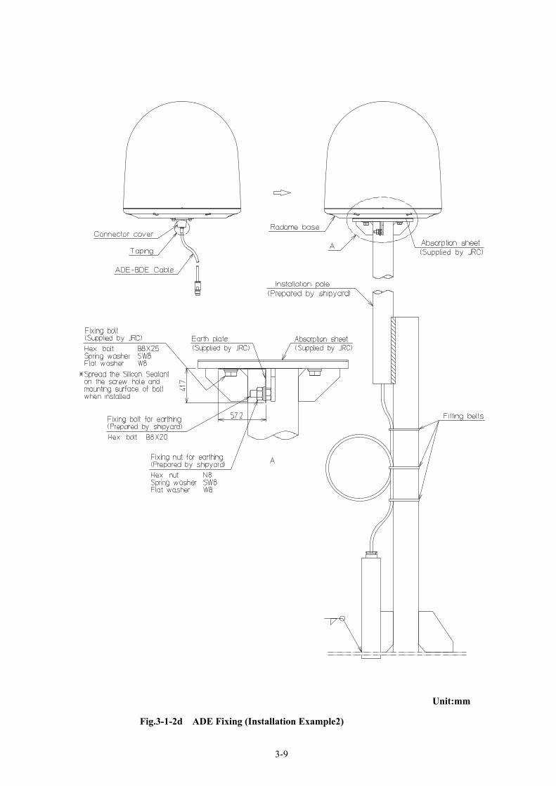
Table 1-6-1 Supplied parts by JRC for Installation No. Part Description Q’ty Material Application 1 2 3 4 5 6 7
Hex. bolt B8x25 Absorption sheet Earth cable Fixing screwM4x20 Fixing screwM5x16 Nylon clip Connector cover
BRTG04310 MTT 311265 MPXP 33501 BRTG04831 BRTG05285 BRBP00005 MTV304176A
4 1 1 1 4 1 1
SUS304
SUS304 SUS304
ADE fixing ADE fixing Earth cable fixing
1-6-2 Required cables
Table 1-6-2 Required cables
Coaxial Cable (ADE-BDE Cable): JRC type.CFQ-5924A3/CFQ5924A15 Length 30m/15m Cable diameter 8mm (not including connecter) Minimum bending radius 46mm Remarks With TNC connectors 1-6-3 Required tools
Table 1-6-3 Required Tools
No. Tool Description (unit: mm)
1 Socket wrench set 1 set
2 Opened- ended spanner Nominal 13 (for M8)
3 Opened- ended spanner Nominal 18 (for M12)
4 Screw driver 1 set (including cross point drivers)
5 Hex. wrench M8, M12

1-9
1-7 Configuration (Optional components) 1-7-1 Telephone [NQW-132B]
Fig. 1-7-1a Telephone
Unit : mm Mass:0.7kg

1-10
Telephone mounting procedure
Fig. 1-7-1b Telephone mounting procedure
1-11
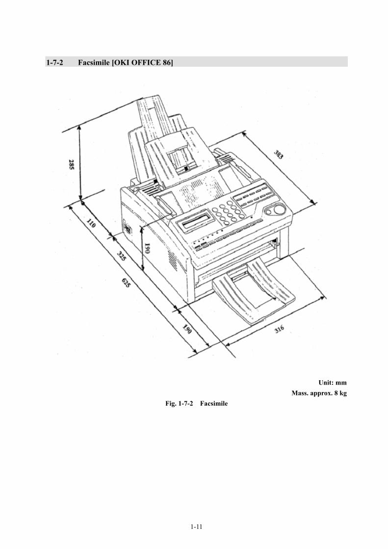
1-7-2 Facsimile [OKI OFFICE 86]
Unit: mm
Mass. approx. 8 kg Fig. 1-7-2 Facsimile

1-12
1-7-3 EXT. PSU (External Power Supply Unit) [NBD-577C]
Caution
Before installation, proceed the following. 1. Set the inner plug “P1” to suitable receptacle
according to the input voltage. 2. Stick the attached label for voltage indication
on the name plate according to the input voltage.
Unit: mm Mass. approx. 5.4 kg
Fig. 1-7-3 External PSU (Power Supply Unit)
AC input Voltage: +110VAC / +220VAC Voltage range: +90VAC to +132VAC / +180V AC to +264VACFrequency: 50Hz/60Hz
DC input Voltage: +24VDC Voltage range: +21.6VDC to +31.2VDC
DC output
Voltage: +24VDC (Typical)
1-13
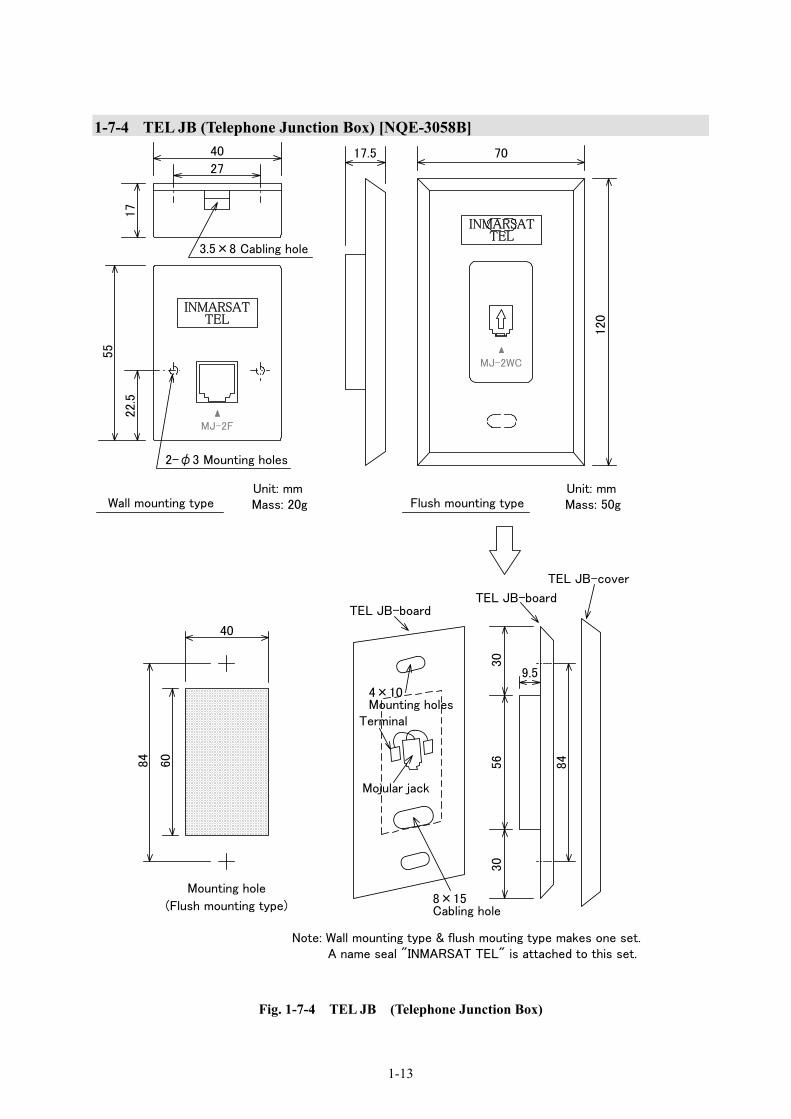
1-7-4 TEL JB (Telephone Junction Box) [NQE-3058B]
Mounting hole
TELEPHONE JOINT BOX (NQE-3058B)
Unit: mmMass: 50g
40
(Flush mounting type)
120
MJ-2WC
7017.5
56
30
30
84
9.5
TEL JB-cover
TEL JB-boardTEL JB-board
Terminal
Mojular jack
8×15Cabling hole
4×10Mounting holes
84
60
MJ-2F
55
40
17
Unit: mmMass: 20g Flush mounting typeWall mounting type
27
22.
5
2-φ3 Mounting holes
3.5×8 Cabling hole
INMARSATTEL
INMARSATTEL
A name seal "INMARSAT TEL" is attached to this set.Note: Wall mounting type & flush mouting type makes one set.
Fig. 1-7-4 TEL JB (Telephone Junction Box)

1-14
1-7-5 GYRO I/F Box [NQA-2066]
Fig. 1-7-5 GYRO I/F Box
Unit: mm Mass:2.5kg
1-15
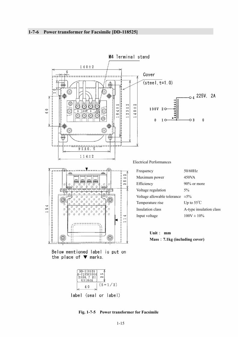
1-7-6 Power transformer for Facsimile [DD-118525]
Electrical Performances
Frequency 50/60Hz Maximum power 450VA Efficiency 90% or more Voltage regulation 5% Voltage allowable tolerance ±5% Temperature rise Up to 55℃
Insulation class A-type insulation classInput voltage 100V ± 10%
Unit: mm Mass:7.1kg (including cover)
Fig. 1-7-5 Power transformer for Facsimile

1-16
2-1
2. INSTALLATION
2-1 ADE Antenna assembly is composed of three axes controlled by servo mechanism. This mechanism is designed and manufactured with careful consideration for long use under the severe environmental condition at sea. When the ADE is installed in higher position to avoid the physical obstruction, the ADE may be often exposed to the severe vibration condition. Therefore, special attention should be paid in such an installation site to reduce vibrations.
NOTE
・ADE should be installed 5m or more away from MF/HF antenna.
・ADE should be installed 3m or more away from VHF.
・ADE should be installed 5m or more away from Direction finder.
・ADE should be installed more than 2m from outside of the rotating area of radar scanner and also avoid transmission area of radar scanner.
・ADE should be installed avoiding heat and smoke of funnel and much dust.
・ADE should be installed avoiding severe vibration and shock.
2-1-1 Plan of installation site
Decide the installation site and antenna height, which satisfies the above NOTE and which can reduce the physical obstruction between a satellite and the ADE.
2-2
2-2 Design of Pole Pole should be designed on the basis of load specification. 2-2-1 Example of pole Design a pole with referring to Fig. 3-1-1a, and 3-1-2a. 2-2-2 Load specification and basic design. Load specification at the top of installation pole is shown in Fig. 2-2-2a. Actual load applied on the installation site should be calculated according to the height of installation pole. The structure of installation site should have adequate stiffness to withstand against the Mass, bending moment and vibration of the ADE and installation pole. Check the vibration level on sea trial as much as possible. Allowable vibration level is 0.7G (686 gal) or less at the top of installation pole as shown in Fig. 2-2-2b. Also, the vibration level will be easily known by Fig. 2-2-2b.

2-3
Loading condition of ADE
Fig. 2-2-2a Loading condition of ADE
ADE Mass (Including ADE installation parts)
Approx. 7.4kg
Maximum wind pressure at wind velocity (Wind speed:52m/sec)
30N
Maximum bending moment at wind velocity (Wind speed:52m/sec)
15Nm

2-4
Allowable acceleration of ADE
Fig. 2-2-2b Allowable acceleration

3-1
3. Installation work 3-1 ADE The ADE should be installed in accordance with the following procedure.
(1) Weld the pole to installation site to the FWD mark on the ADE facing to ship’s forward. At this time, the FWD mark on the ADE should be in the range of ±1.5°to forward. (Refer to Fig. 1-5-1.)
(2) Put through the ADE-BDE cable (coaxial cable) into connecter cover.
(3) Attach the Coaxial cable to the connector of the bottom of radome.
(4) Spread the silicon sealant on the ditch in the upper part of connector cover in the proper quantity, and install it at the bottom of radome. At this time, confirm that the vent hole is not sealed with the silicon sealant very well. (Refer to Fig. 3-1-1b or Fig. 3-1-2b.)
(5) Taping at the bottom of connector cover. (Refer to Fig. 3-1-1c or 3-1-2c.)
(6) Stick absorption sheets on the top of the installation pole. (Refer to Fig. 3-1-1b or 3-1-2b.)
(7) Install the ADE on the pole. The FWD mark of radome base should be in the range of ±1.5°to forward. (Refer to Fig. 1-5-1.)
(8) Take enough loosening to the cable when mounting radome. After mounting ADE fixing screw, spread the Silicon Sealant on the screw hole and surface of bolt when installed.
(9) Wrap the cable at least one time to the pole and fix it so that the cable does not receive any power. (Refer to Fig. 3-1-1d or 3-1-2d.)
Recommended support structure Installation on mast Pole should be installed on the top of the mast or top of the platform having sufficient strength. Whole mast structure should have adequate stiffness against the mass, bending moment and vibration of ADE and installation pole.
CAUTION
Keep out of the area within a radius of 4.5meters from your ADE, because ADE transmits microwaves. Strong microwaves may cause injury. Turn JUE-250 off and stop transmitting if you approach within a radius of 4.5meters by necessity.
Do not deliver mechanical shock and/or force, because each unit of your ADE is a precision instrument. Unwanted shock and force may cause malfunction.
Do not paint radome. Painting of radome may cause decrease of the communication quality.

3-2
3-1-1 Installation Example1 (Pole installation to ADE fixing)
Fig.3-1-1a Pole designing (Installation Example1)
Unit:mm

3-3
Fig.
3-1-
1b
Spre
adin
g Si
licon
Sea
lant
(Ins
talla
tion
Exa
mpl
e1)

3-4
Fig.
3-1-
1c
Tapi
ng c
onne
ctor
cov
er (I
nsta
llatio
n E
xam
ple1
)

3-5
Fi
g.3-
1-1d
C
able
Fix
ing
(Ins
talla
tion
Exa
mpl
e1)
3-6
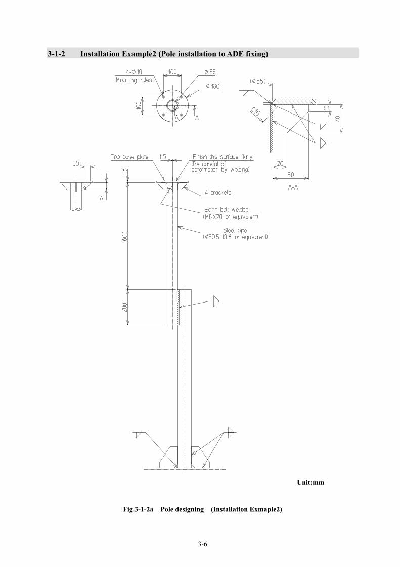
3-1-2 Installation Example2 (Pole installation to ADE fixing)
Fig.3-1-2a Pole designing (Installation Exmaple2)
Unit:mm

3-7
Fig.
3-1-
2b
Spre
adin
g Si
licon
Sea
lant
(Ins
talla
tion
Exam
ple2
)

3-8
Fig.
3-1-
2c
Tapi
ng c
onne
ctor
cov
er (I
nsta
llatio
n E
xam
ple2
)
3-9
Fig.3-1-2d ADE Fixing (Installation Example2)
Unit:mm
3-10
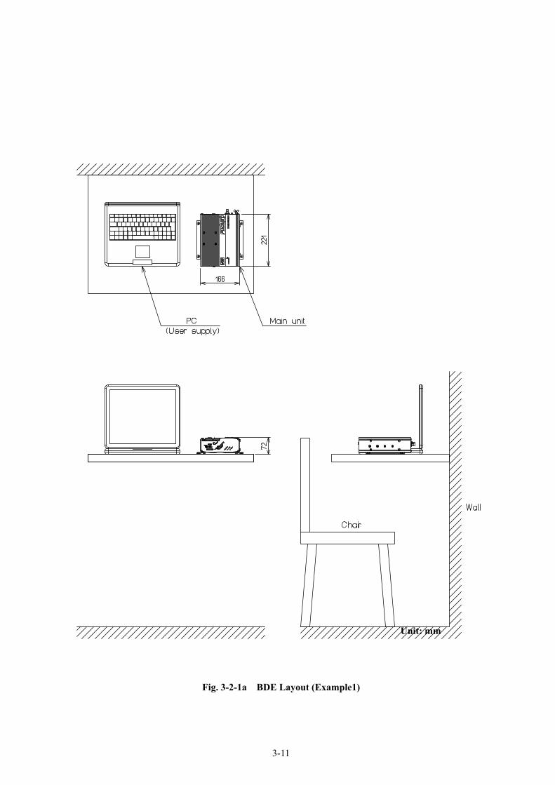
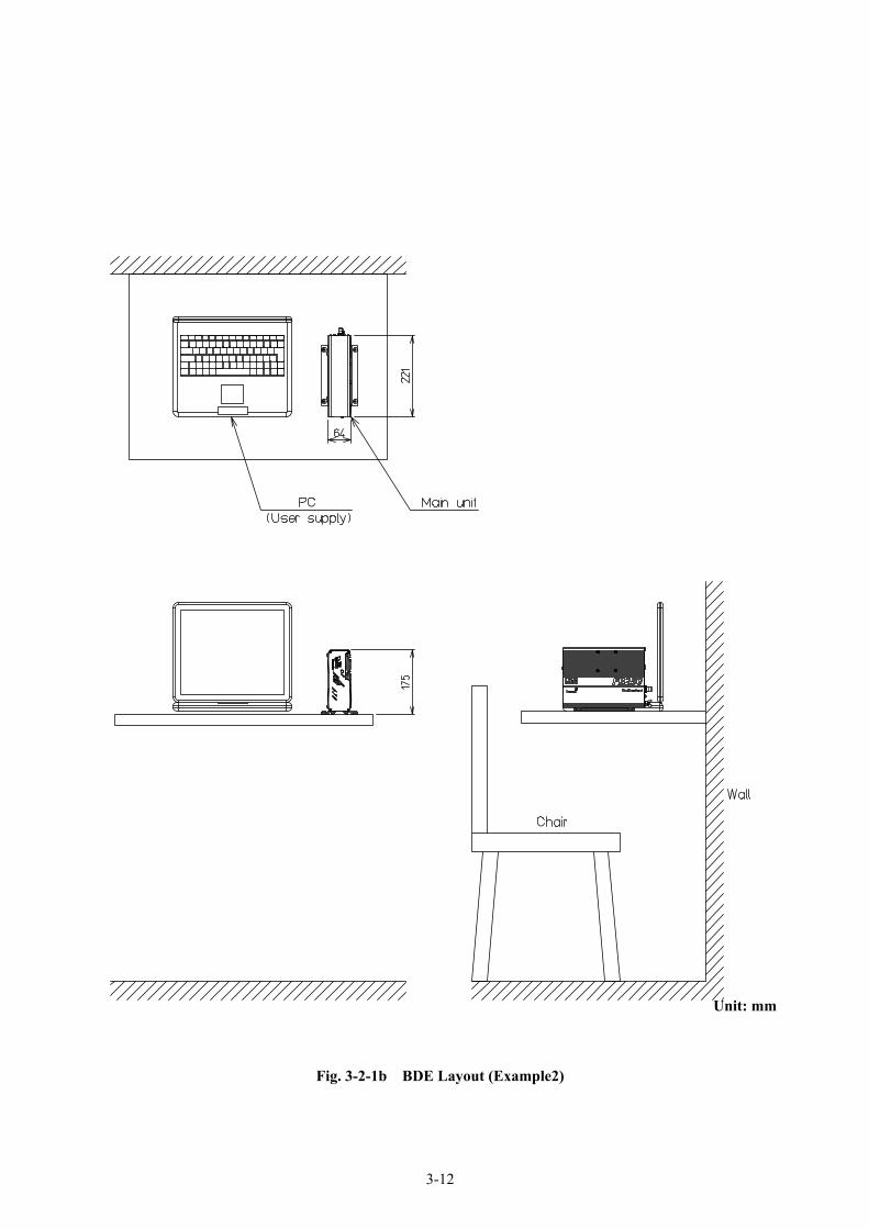
3-2 BDE Installation Installation site of Main Unit, Handset should be determined taking into consideration their feasibility and maintainability.
NOTE
・ The Main Unit and Handset should be installed 2.5 m or more away from MF/HF antenna feeders. Otherwise, it may cause malfunction.
・ The earth terminals of Main Unit should be grounded with cable. Otherwise, it may cause malfunction. ・ Do not insert nonconforming cards into the USIM card slot of Main Unit front panel.
Do not insert wrong side of the card. These may cause slot malfunction.
・ If antenna bar is displayed fewer than 3, communication-connection rate may fall due to the system
design depending on communication mode, although READY is displayed in STATUS area of the LCD.
CAUTION
Connect the ground terminal of the Main Unit to bulkhead or floor with grounding cable. Poor connection may cause malfunction.
3-2-1 Main Unit Main Unit should be installed in accordance with the following procedure: (1) Mount Earth cable to bulkhead. (2) Connect Earth cable and each cables to Main Unit.
Ensure Main Unit installing dimensions to be agreed with the dimensions of Fig. 3-2-1e.
3-11
Fig. 3-2-1a BDE Layout (Example1)
Unit: mm
3-12
Unit: mm
Fig. 3-2-1b BDE Layout (Example2)
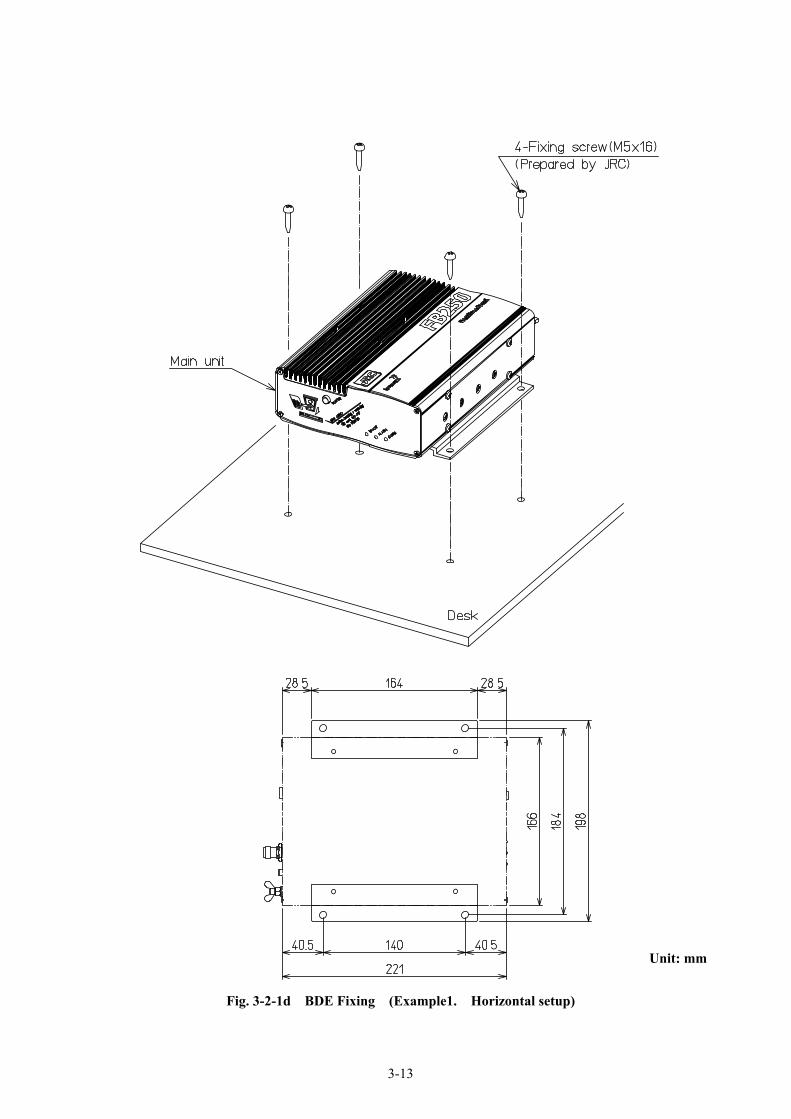
3-13
Unit: mm
Fig. 3-2-1d BDE Fixing (Example1. Horizontal setup)
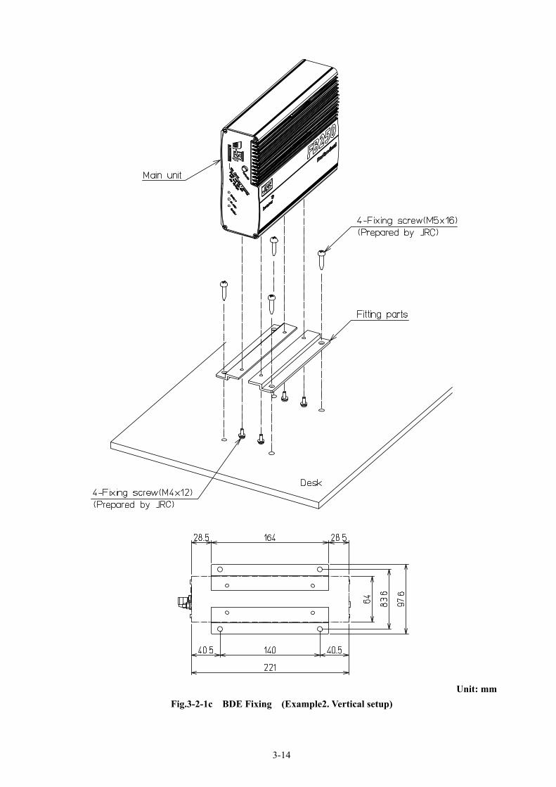
3-14
Unit: mm Fig.3-2-1c BDE Fixing (Example2. Vertical setup)

3-15
Unit: mm
Fig.3-2-1e Cable connecting to Main unit

3-16
WRF
Ethernet
Fig. 3-2-1f Rear view of Main unit
Earth ADE POWER FUSE
TEL/FAX Handset USB Audio (ISDN)

3-17
⇒
3-2-2 Handset 1. Required parts
The following required parts for wall mount are attached to the Handset.
Parts number Description Q’ty 1 Wall mount bracket 1 2 Wood screw 4 × 10 2 3 Screw 3 × 6 1
2. Installation procedure
(1) Fix the mount bracket 1 on the
wall with two fixing screws 2.
NOTE
Do not tighten up fixing screws too much, because the mount bracket will be distorted
(2) Catch the lower side ditches of the holder a by the lower side bending of mount bracket b. Fix the mount bracket with fixing screw 3.
Fig. 3-2-2 Handset (Cradle) Mounting
1
2
a
b
3

3-18
3-2-
3 G
YR
O I/
F B
OX
In
stal
l the
GY
RO
I/F
box
and
BD
E re
ferr
ing
to fo
llow
ing
proc
edur
e.
U
nit:
mm
Fig.
3-2-
2c F
ixin
g pr
oced
ure
of G
YR
O I/
F bo
x an
d M
ain
unit
(*O
nly
whe
n G
YR
O is
use
d)
Fig.
3-2
-3a
BD
E la
yout
(A
ll-in
-one
type
) Fi
g. 3
-2-2
b B
DE
layo
ut
(Sep
arat
e ty
pe)
Fig.
3-2
-2c
BD
E la
yout
(S
epar
ate
and
vert
ical
type
)

3-19
Fig.
3-2-
2e
BD
E la
yout
(sta
ndin
g in
stal
latio
n)
(*O
nly
whe
n G
YR
O is
use
d)
U
nit:
mm
All-
in-o
ne ty
pe
Sepa
rate
type
Fig.
3-2-
2d
BD
E la
yout
(hor
izon
tal i
nsta
llatio
n)(*
Onl
y w
hen
GY
RO
is u
sed)
Fig.
3-2-
2f
Posi
tion
rela
tion
of m
ount
ing
hole
s an
d G
YR
O I/
F bo
x
3-20
U
nit:
mm
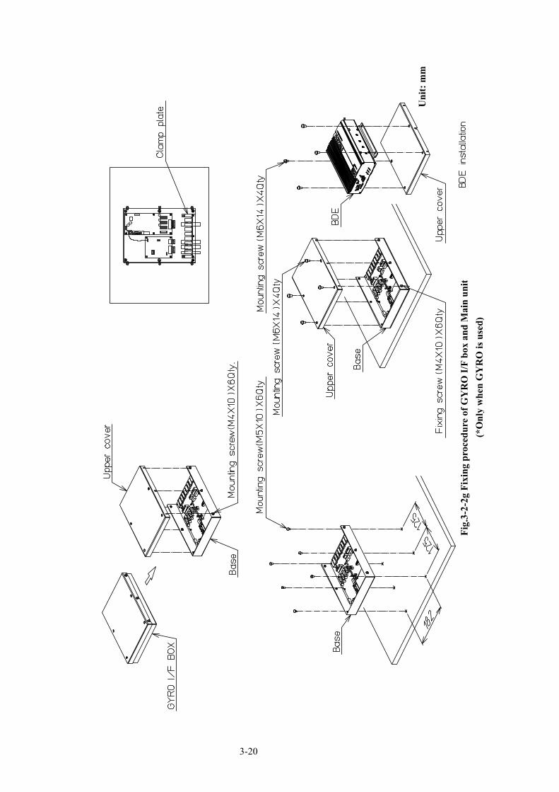
Fig.
3-2-
2g F
ixin
g pr
oced
ure
of G
YR
O I/
F bo
x an
d M
ain
unit
(*O
nly
whe
n G
YR
O is
use
d)

3-21
Unit: mm
Fig. 3-2-2h Cable connecting to Main unit (*Only when GYRO is used)
3-22
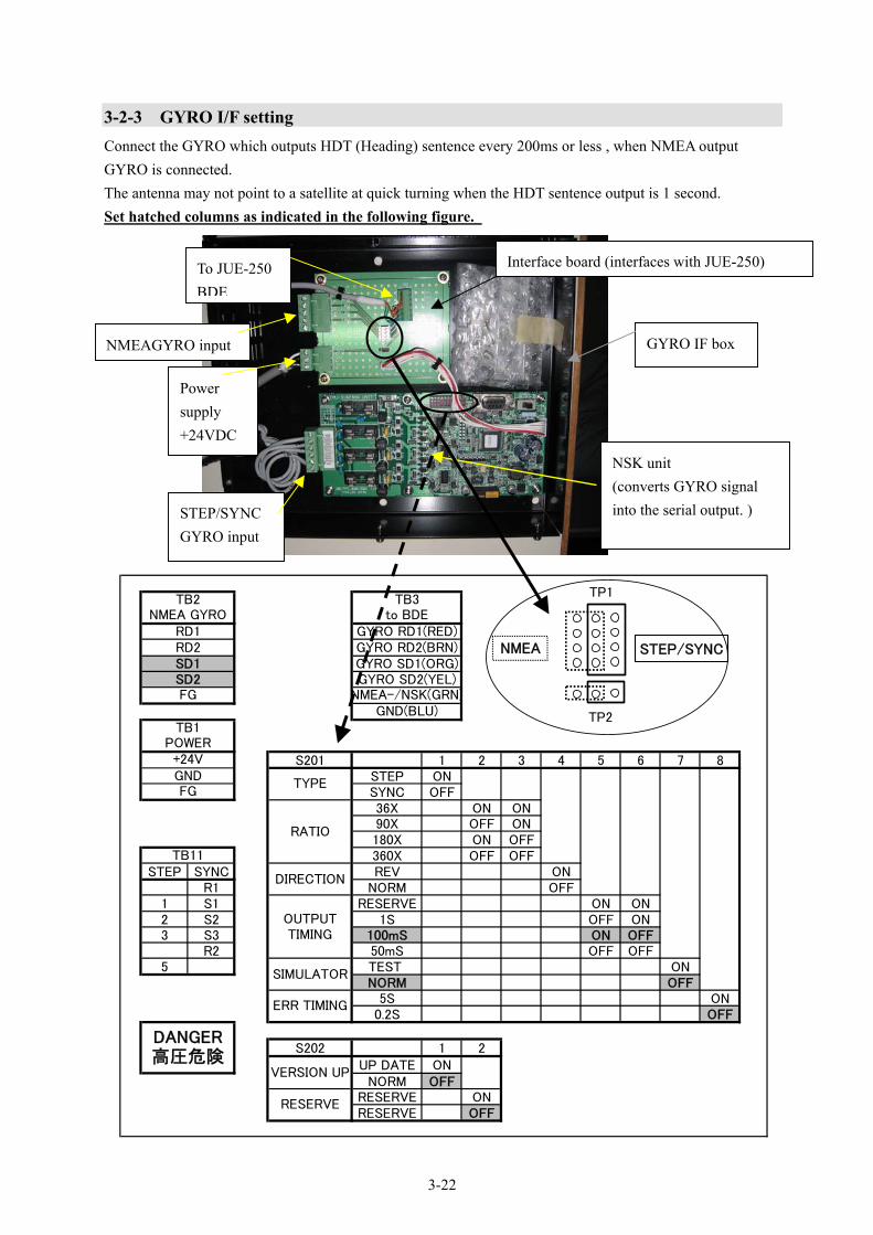
3-2-3 GYRO I/F setting Connect the GYRO which outputs HDT (Heading) sentence every 200ms or less , when NMEA output GYRO is connected. The antenna may not point to a satellite at quick turning when the HDT sentence output is 1 second. Set hatched columns as indicated in the following figure.
GYRO IF box
NSK unit (converts GYRO signal into the serial output. )
Interface board (interfaces with JUE-250)
STEP/SYNCGYRO input
Power supply +24VDC
NMEAGYRO input
To JUE-250 BDE
S201 1 2 3 4 5 6 7 8STEP ONSYNC OFF36X ON ON90X OFF ON180X ON OFF360X OFF OFF
STEP SYNC REV ONR1 NORM OFF
1 S1 RESERVE ON ON2 S2 1S OFF ON3 S3 100mS ON OFF
R2 50mS OFF OFF5 TEST ON
NORM OFF5S ON
0.2S OFF
S202 1 2UP DATE ON
NORM OFFRESERVE ONRESERVE OFF
GND(BLU)NMEA-/NSK(GRN)
TB3to BDE
GYRO RD1(RED)GYRO RD2(BRN)GYRO SD1(ORG)GYRO SD2(YEL)
TB2NMEA GYRO
RD1
TB11
RD2SD1SD2FG
TB1POWER+24VGND
VERSION UP
RESERVE
FG
OUTPUTTIMING
SIMULATOR
ERR TIMING
TYPE
RATIO
DANGER高圧危険
DIRECTION
TP1
TP2
NMEA STEP/SYNC
3-23
3-3 Cable Cable connection system diagram is shown in Fig1-3, Connection to Main Unit is shown in Fig.3-2-1f. Cable connection should be made in accordance with these figures. 3-3-1 Cable routing
NOTE
Do not cut off the ADE-BDE coaxial cable. Coil and secure the coaxial cable in convenient compartment such as between the Main Unit and bulkhead. Otherwise, a trouble may occur.
CAUTION
<<Coaxial cable>>
Install JUE-250 ADE-BDE coaxial cable correctly in accordance with the installation manual. Especially waterproof should be treated correctly in accordance with the installation manual. Inappropriate installation may cause incorrect operation, fire, electrical shock or malfunction. Coaxial cable should be installed by the special technician or skilled engineer. The installation should be requested to the purchasing dealer, JRC agent or one of the JRC branches.
<<Coaxial cable and the other cables>>
Take care not to damage the connectors and the corrosion resistant sheath of cable. Otherwise, a trouble may occur.
Do not pull the cable by gripping connector plug only. Otherwise, a trouble may occur.
(1) The connector plugs installed on both coaxial cable ends are adaptable to connector receptacles of either ADE or BDE.
(2) The minimum bending radius of cable is 46mm (When using standard cable). (3) Referring to Fig.1-3, route cables. 3-3-2 Connection to ADE Connection of ADE coaxial cable to ADE should be made in accordance with the following procedure. (1) The connector cover is passed through the cable first.
(2) Connect the connector of Coaxial cable to the connector of ADE, which is on the central bottom of ADE.
(3) Screw the connector cover into bottom of ADE.
(4) Wrap the tape around the lower part of connector cover.

3-24
3-3-3 Connection to BDE Cable connection to Main Unit and Junction Box should be performed in accordance with the following procedure.
NOTE
Do not connect or disconnect the coaxial cable when the main unit turns on. Power is supplied from ADE connector on back of the Main Unit, a short circuit may cause malfunction.
(1) Connect the Coaxial cable to the coaxial connector on back of the Main Unit.
(2) Connect the Power cable to the connector on back of the Main Unit.
(3) Confirm the Coaxial and Power cable have been connected completely.
(4) Connect the Handset cable to the Handset port on back of the Main Unit.
NOTE
When Handset is installed in the room with MF/HF transmitter, keep the Handset cable 2.5m or more away from MF/HF antenna feeders.

3-25
3-3-4 Connection to primary Power
NOTE
Perform above item 3-3-1 through 3-3-3 completely before connection of Primary Power cable. Otherwise, you will get electrical shock and/or a trouble may occur.
(1) Connect the power cable to convenient ship's Power distribution box (refer to Fig.1-3). Connector pin number, signal name and color is as follows;
1 : +24VDC RED 2 : Frame GND GRN 3 : Signal GND BLK (2) Connect power cable referring to fig. 1-3 when External PSU (NBD-577C) is used. 3-3-5 Abandonment work ・ Keep the rule of the pertinent local government when you abandon the package materials of the
JUE-250. ・ Keep the rule of the local government when you abandon the JUE-250 (ADE).
For details, contact the dealer, our service office (Refer to the list of offices at the end of the volume) or
a concerned local government.

3-26

4-1
4. SPECIFICATION 4.1 JUE-250 Standard components 4.1.1 ADE and BDE
Transmit 1626.5 to 1660.5 MHz 1. Frequency
Receive 1525.0 to 1559.0 MHz
2. Channel Step 1.25kHz 3. Maximum E.I.R.P +15.1dBW + 1/-2dB
4. G/T -15.5dBK Type 0.30 flat
Polarization Right-Hand Circular Polarization (RHCP)
Radome AES
QPSK
π/4-QPSK
5. Antenna
16QAM
For voice
Voltage +19VDC to +31VDC Current Under 2A, as the time of receipt
7. Primary Power
Maximum Under 4.5 A, as the time of transmitted, and optional equipments are connected.
8. Dimension ADE 350mm x h350mm BDE h166mm x w64mm x d221mm Mass ADE 7.4kg BDE 2.2kg
9. Environmental Conditions
ADE -25˚C to +55˚C 1) Temperature
BDE -15˚C to +55˚C 2) Relative Humidity Up to +40˚C, 95%
3) Vibration Complying with IEC60945 4th Edition
Motion Amplitude Period
Roll +30˚ 8 s
Pitch +10˚ 6 s
Yaw +8˚ 50 s
Surge +0.2g
Sway +0.2g
Heave +0.5g
Turning Rate +6˚ /s 1deg/s2
4) Ship’s Motion
Headway 30knots

4-2
Infrared Radiation 500 watts / m2 5) Solar Radiation (ADE)
Ultraviolet Radiation 54watts / m2
6) Icing (ADE) Up to 25mm
7) Precipitation Up to 100mm / hour
8) Wind Up to 100knots in operation

5-1
5. JRC Network Please contact the dealer from which you purchased the device or our marketing offices that is nearest to you for any question as to the after-sales service.
JRC Tokyo Japan http://www.jrc.co.jp JRC Amsterdam http://www.jrcams.nl JRC Seattle http://www.jrcamerica.com
Edition 1.0 (2007.12.05)
JRC web site