Judicious Energy Management in Wireless Sensor Networks · Judicious Energy Management in Wireless...
13
I J C T A, 9(20), 2016, pp. 245-257 © International Science Press Judicious Energy Management in Wireless Sensor Networks Anju* and Rishi Pal Singh** ABSTRACT A Wireless Sensor Network (WSN) uses battery operated computing and sensing nodes which may lose its energy after certain amount of lifetime within the network. Papers so far dealing with the outdoor wireless sensor networks consider the battery included in the sensor node to be of photovoltaic nature which may recharge itself with the solar energy medium but do not guarantee the upliftment of energy level up to hundred percent every time, as a number of environmental factors may also participate during this activity. Besides the availability of solar rechargeable batteries, a major part of the research in wireless sensor networks so far emphasizes the procedures to improvise the energy efficiency among the data centric nodes in the network. But, it would be much advantageous if the research so far steered towards the provision of continuous energy within the sensors through passive medium and outperform throughout the lifetime as in the wired networks. The paper intends to model a new framework which involves improvising the energy level of each sensor node within the network by providing an algorithm for intelligent energy utilization and monitoring the levels of sensor node energy with a provision for passive charging system for each sensor node in the deployment area. Keywords: wireless sensor network; sensor nodes; base station; energy efficiency; judicious energy management; power supply model; energy balancing model 1. INTRODUCTION With the recent advances in the wireless communication technology, wireless sensor networks are marking their importance with their small size and low cost sensor nodes connected by wireless media to form a new class of communication network in which various small size nodes can be used to sense the environment, collect data from the environment and forward to the end user through base stations. The data may include environmental measurements of sound, light, moisture, temperature or other relevant parameters. Covering these or other parameters, wireless sensor networks are finding their importance in various applications like home application, health monitoring, biological detection, surveillance of remote or hostile or battle area, inventory tracking, national security, smart spaces, disaster relief, military surveillance, habitat monitoring, target tracking, sick building syndrome etc. [1-6]. In all these wireless sensor networks applications, network lifetime has remained a critical aspect as power resources small sized due to weight limitations.The network lifetime in general referred to as the time interval within a network is able to sense the data as well as transmit the sensed data. To enhance the lifetime of the network, two primary techniques of energy conservation are always focused: adjusting the coverage area i.e. sensing and/or transmitting range of these nodes and alternating the sensor nodes scheduling between sleep and active mode.Such energy conservation techniques play a vital role where the sensing is being done in the hostile environment. Optimal sensor deployment strategy in the hostile environment aims to save energy and enhance the lifetime of the network. Due to huge number of sensors in wireless sensor * Department of Computer Science & Engineering, Guru Jambheshwar University of Science & Technology, Hisar, India, Email: [email protected], ** Department of Computer Science & Engineering, Guru Jambheshwar University of Science & Technology, Hisar, India, Email: [email protected]
Transcript of Judicious Energy Management in Wireless Sensor Networks · Judicious Energy Management in Wireless...

I J C T A, 9(20), 2016, pp. 245-257© International Science Press
Judicious Energy Management inWireless Sensor NetworksAnju* and Rishi Pal Singh**
ABSTRACT
A Wireless Sensor Network (WSN) uses battery operated computing and sensing nodes which may lose its energyafter certain amount of lifetime within the network. Papers so far dealing with the outdoor wireless sensor networksconsider the battery included in the sensor node to be of photovoltaic nature which may recharge itself with thesolar energy medium but do not guarantee the upliftment of energy level up to hundred percent every time, as anumber of environmental factors may also participate during this activity. Besides the availability of solar rechargeablebatteries, a major part of the research in wireless sensor networks so far emphasizes the procedures to improvise theenergy efficiency among the data centric nodes in the network. But, it would be much advantageous if the researchso far steered towards the provision of continuous energy within the sensors through passive medium and outperformthroughout the lifetime as in the wired networks. The paper intends to model a new framework which involvesimprovising the energy level of each sensor node within the network by providing an algorithm for intelligentenergy utilization and monitoring the levels of sensor node energy with a provision for passive charging system foreach sensor node in the deployment area.
Keywords: wireless sensor network; sensor nodes; base station; energy efficiency; judicious energy management;power supply model; energy balancing model
1. INTRODUCTION
With the recent advances in the wireless communication technology, wireless sensor networks are markingtheir importance with their small size and low cost sensor nodes connected by wireless media to form anew class of communication network in which various small size nodes can be used to sense theenvironment, collect data from the environment and forward to the end user through base stations. Thedata may include environmental measurements of sound, light, moisture, temperature or other relevantparameters. Covering these or other parameters, wireless sensor networks are finding their importancein various applications like home application, health monitoring, biological detection, surveillance ofremote or hostile or battle area, inventory tracking, national security, smart spaces, disaster relief, militarysurveillance, habitat monitoring, target tracking, sick building syndrome etc. [1-6]. In all these wirelesssensor networks applications, network lifetime has remained a critical aspect as power resources smallsized due to weight limitations.The network lifetime in general referred to as the time interval within anetwork is able to sense the data as well as transmit the sensed data. To enhance the lifetime of thenetwork, two primary techniques of energy conservation are always focused: adjusting the coverage areai.e. sensing and/or transmitting range of these nodes and alternating the sensor nodes scheduling betweensleep and active mode.Such energy conservation techniques play a vital role where the sensing is beingdone in the hostile environment. Optimal sensor deployment strategy in the hostile environment aims tosave energy and enhance the lifetime of the network. Due to huge number of sensors in wireless sensor
* Department of Computer Science & Engineering, Guru Jambheshwar University of Science & Technology, Hisar, India, Email:[email protected],
** Department of Computer Science & Engineering, Guru Jambheshwar University of Science & Technology, Hisar, India, Email:[email protected]

246 Anju and Rishi Pal Singh
networks, the total cost will be high for entire network, though cost of the individual sensor is very low.Therefore, it is essential to identify minimum number of nodes that needed for wireless sensor networksto achieve uplifting of energy. Since, the coverage area of each sensor node can be adjusted so, it isalways preferred for hostile environment that the sensor nodes perform for maximum period in responseof adjusting the range of each sensor node to low coverage area and switching their lifecycle to sleep andactive modes. Many of the papers [7-9] have suggested energy efficient coverage techniques but eachone of them prolong the life time or coverage area rather than an approach in which energy efficiencymay extend the coverage of a node or whole network to maximum till the user wants to sense the dataindependent of the sensor life or without replacing them physically. It would always be appreciable ifeach one of the sensor node in the deployment area outperform in terms of coverage i.e. each nodecovers maximum area, as this would reduce the demand of number of redundant sensor nodes in the areaand thus decreasing the overall physical structure cost of the network. This paper aims to provide a clearoverview about uplifting the energy in wireless sensor networks. This paper will help the future researchersto know about uplifting energy in wireless sensor networks through a passive energy recharge model, inwhich sensor nodes are recharged explicitly, working in co-ordination with a judicious model for energymanagement that will balance the energy level among the sensor nodes dynamically in the deploymentarea.This will also affect the energy aware coverage problems in wireless sensor networks that are attractinglot of research interest these days. The network coverage is one of the most critical issue to implementWSNs due to limited resources in each sensor node, hence it is critically important to provide requiredenergy in an energy efficient way.To fix energy aware network coverage issues in wireless sensor networks,mostly models adopt boolean sensing model to meet the coverage requirements in which a subset ofsensor nodes with minimum weights is selected, termed as Minimum Weight Sensor Coverage Problem(MWSCP) in which the sensor nodes with more residual energy are activated to balance the energyconsumption and extend the network life [23].
2. MOTIVATION
In providing various applications, wireless sensor networks may find challenges in maintaining theenergy efficiency among nodes, security in the network, making the system to be fault tolerant,dissiminating the data throughout the network, connecting to the neighbor nodes or managing thecoverage of sensor nodes within the network. In each one of the challenge, another challenge is alwaysassociated either actively or passively, that is; the small sized battery limitation. This small sizedbattery of the sensor nodes is founding direct or indirect involvement of energy efficient system.Many researchers have proposed a number of algorithms or protocols to make the system energyefficient but an energy efficient system can uplift the lifetime of the network to some extent and cannever make it working permanantly as with the fixed or wired system that has always an external andcontinuous power supply.Somehow, a ray of light is directed when a thought of implementing theconcept of wireless electricity transmission over the field of wireless sensor network stiked. Wirlesselectricity is becoming a hot and demanding topic in the research day by day. The evolution startedwith the solar charging [18] follwed by charging models of space crafts and wireless power transmissions[12-15], then focussed to UAV chargings [16] and now in domestic applications as well. Though thefeature was introduced in wireless sensor networks [17] and later in [11] but the bottleneck in this partwas the usage of power beams which may be harmful for humans or any living obstruction that maycome in the between the source and the destination. The main crux of this model was the rise in thecost of the network due to the involvement of extra hardware. So, to reduce the cost to some extent,the number of nodes have been reduced to 60%, as in generic techniques the remaining 40% of thenodes generally either provide duplicate information or may provide redundancy. Since, the more isthe number of nodes more will be latency time, whether it be in micro seconds or a few seconds, for anode to get itself charged.

Judicious Energy Management in Wireless Sensor Networks 247
3. THE PROPOSED MODEL
The paper proposes a Judicious Energy Management (JEM) model which is divided into two maincomponents:
A. Power Supply Model (PSM)-that will provide the provision for recharging sensor nodes with passiveenergy i.e. other than the solar energy.
B. Energy Balancing Model (EBM)-that will balance the energy level of all the sensor nodes in thenetwork and allow the PSM to recharge the sensor node if its energy performance is below the scale.
In Judicious Energy Management, both the components will work in co-ordination with each otherthroughout the network lifetime in order to enhance the network efficiency, as shown in Figure 1.
Figure 1: Block Diagram of Judicious Energy Management
3.1. Power Supply Model
The Power Supply Model (PSM) considers a wireless sensor network to be deployed in a hostile environmentwith fixed position of sensor nodes for long term sensing requirement of the field. PSM constitutes some
Figure 2: (a) Network arrangement at abstract level

248 Anju and Rishi Pal Singh
extra infrastructure including three charging stations and a different kind of power unit in the sensor node;inspired by [10].
The model constitutes of three charging station A, B, C, placed on three different sides of the deploymentarea, a base station and a deployment area constituting sensor nodes, as shown in Figure 2 (a). The chargingstations constitutes an adaptive-phased array microwave emitters and they form a two way communicationwith the Base Station (BS) and the Sensor Nodes (SN) in the deployment area, Figure 2(b) shows themicrowave charging procedure of the sensor nodes and the base station. The Figure3 shows the elaborativeworking of the model with the help of block diagram. The charging station and the sensor nodes constitutethe following main components:
• Adaptive Phased Array- The power transmitter portion contains one or more number of adaptive-phase array emitters which can focus on the sensor nodes or the base station to be charged. Theadaptive-phased arrays normally operate between the frequency range of 2 GHz to 10 GHz, howeverhigher frequencies can also be employed which may be in lower in efficiency [10].
• Pilot Beam Detector- Its role is to detect a locator signal emitted by a pilot beam emitter in thesensor node.
• Backscatter Sensor- It is associated with the adaptive phase arrays of the charging station anddetects any obstacle entering in the path of microwave beam sent through the charging station. Theobstruction may be some human interference or in any other way. If the backscatter sensor sensessome interference in the beam path then the adaptive-phased array associated with it will eitherturned off or reduce the beam concentration. The process preevents wastage of the microwavepower which is not reaching its destination and damage to humans or any other interference withinthe path. The beam transmission will be held until the obstruction is removed from the beam path.
• Location Beam Detectio- It helps in detecting the location of sensor nodes in the deployment area.In this model, virtual and local co-ordinates are obtained with respect to three charging stationsusing triangulation technique [19].
• Control Logic- It controls the beam intensity if any obstruction arises while transmitting the beam.
• Energy Source- It is the power genrator that may contain AC or DC supply and helps the chargingstation to convert this electric power into microwave power that is to be further supplied to chargethe nodes in the network.
Figure 2: (b) Two-way communication for charging the network nodes
Judicious Energy Management in Wireless Sensor Networks 249
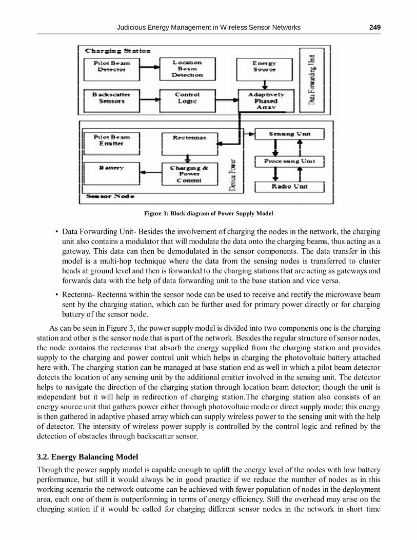
• Data Forwarding Unit- Besides the involvement of charging the nodes in the network, the chargingunit also contains a modulator that will modulate the data onto the charging beams, thus acting as agateway. This data can then be demodulated in the sensor components. The data transfer in thismodel is a multi-hop technique where the data from the sensing nodes is transferred to clusterheads at ground level and then is forwarded to the charging stations that are acting as gateways andforwards data with the help of data forwarding unit to the base station and vice versa.
• Rectenna- Rectenna within the sensor node can be used to receive and rectify the microwave beamsent by the charging station, which can be further used for primary power directly or for chargingbattery of the sensor node.
As can be seen in Figure 3, the power supply model is divided into two components one is the chargingstation and other is the sensor node that is part of the network. Besides the regular structure of sensor nodes,the node contains the rectennas that absorb the energy supplied from the charging station and providessupply to the charging and power control unit which helps in charging the photovoltaic battery attachedhere with. The charging station can be managed at base station end as well in which a pilot beam detectordetects the location of any sensing unit by the additional emitter involved in the sensing unit. The detectorhelps to navigate the direction of the charging station through location beam detector; though the unit isindependent but it will help in redirection of charging station.The charging station also consists of anenergy source unit that gathers power either through photovoltaic mode or direct supply mode; this energyis then gathered in adaptive phased array which can supply wireless power to the sensing unit with the helpof detector. The intensity of wireless power supply is controlled by the control logic and refined by thedetection of obstacles through backscatter sensor.
3.2. Energy Balancing Model
Though the power supply model is capable enough to uplift the energy level of the nodes with low batteryperformance, but still it would always be in good practice if we reduce the number of nodes as in thisworking scenario the network outcome can be achieved with fewer population of nodes in the deploymentarea, each one of them is outperforming in terms of energy efficiency. Still the overhead may arise on thecharging station if it would be called for charging different sensor nodes in the network in short time
Figure 3: Block diagram of Power Supply Model

250 Anju and Rishi Pal Singh
intervals. So, it would always be in good practice to balance the energy level of the nodes in the networkotherwise a few nodes which found often invitation to perform their activities will be charged again andagain while the others will not remain active all the time in the network.
After the successful setup of the network, this model comes into existence. This model constitutes twomain algorithms in order to uplift energy level in wireless sensor networks and they are:
• Algorithm for head selection in cluster
• Dynamic sleep time algorithm
4. HEAD SELECTION ALGORITHM
Judicious Energy Management (JEM) follows the procedure of head selection algorithm which helps to separateentire network into number of clusters. Here, each and every node will be a part of cluster and have a clusterhead (CH).The main objective of the cluster formation in the proposed approach is to balance the energy loadsof cluster heads. Each and every cluster head in the network is responsible only for the received data from thecluster members and it performs aggregation process on the received data and also then to the base station(BS). The base station chooses the CH (cluster head) at the very beginning of each and every round based onthe current information of the nodes.Each cluster is termed as Ci and one of the nodes in the cluster Ci isselected as the cluster head, CHi. The cluster head is responsible for only receiving and routing sensed data ofother sensor nodes which belongs to the cluster and also to the base station. The round by round process isperformed in order to select the cluster head (CH) from the sensor nodes which are in the same cluster. Ingeneral, energy consumption of the cluster head (CH) is higher while comparing with the other nodes. Thecluster head (CH) in the cluster is considered as the alternate among the sensor nodes in order to balance theconsumption of energy for extending the lifetime of the wireless sensor networks (WSNs). Therefore, it isclearly understood that, the selection manner of cluster head (CH) can have capacity to affect the lifetime ofentire network (wireless sensor networks).When the threshold value is higher than the residual energy ofcluster head (CH) node, it triggers new cluster head (CH) candidacy event by reporting the base station that itwas not able to perform its functions as a cluster head (CH) any more. Afterwards, the base station will informthis to all other cluster heads thus by taking action on a cluster head rotation phase. In order to avoid deadlockwhen the older cluster head(CH) dies, the next round CH will be selected in advance.The proposed algorithmrecommends associated cluster head array that contains Location-ID and Node- ID and also suggests decreasingthe residual energy of the sensors. Cluster nodes are mainly used to collect the data from environment andthen send it to the cluster head. While processing of the head node of the cluster, the energy level is reduced.If the energy of cluster head becomes lower to then the energies of the non-CH (cluster head) nodes, then it isessential to process the next round. At that period of time, the proposed algorithm calls the next cluster headfor each cluster in order to start the process of new round.
In the proposed algorithm, physical clusters are assumed i.e.the formation of cluster and members ofeach and every cluster are fixed. So, it does not need any re-clustering process.Following are the sequenceof steps followed for header selection in each cluster:
1. for node := 1: n //n is the total number of nodes
1.1. RADIOnode := 1
1.2. Broadcast locationnode to the BS
1.3. Add node to the cluster Ci based on its location.
2. fori := 1:p //p is the total number of physical clusters
2.1. for node := 1:q //q is the total number of nodes inside ith cluster
2.1.1. TRANSMISSIONnode := 0

Judicious Energy Management in Wireless Sensor Networks 251
2.1.2. RADIOnode := 0
2.2. for node := 1:q
2.2.1. Send information containing energy level to the BS
2.2.2. Find node with Maximumenergy in Ci and mark node as Xi; mark all remaining member nodesin Ci as Y.
2.2.3. Assign Xi as Cluster Head (CH).
2.3. for node:= 1:q
2.3.1. if node != Xi
2.3.1.1. TRANSMISSIONnode := 1
2.3.1.2. RADIOnode := 1
2.3.1.3. Aggregate the data received by Xi and unicast to BS.
3. if Xi-residual_energy<Energythreshold
3.1. goto step 2.
Implementation of cluster formation algorithm has several steps. First step is to setup the process andbroadcast the information about the existing location of sensor nodes to the base station (SINK). The nextstep is to determine good clusters. Then in each and every cluster, all the sensor nodes sent its energy levelto base station. If the sensor node has highest energy level then allows it choosing as cluster head andbroadcast the information to its member nodes, otherwise, it chooses the nodes as the member nodes. As anext step, nodes send data to cluster head (minimal energy is used for transmission) and then the radio ofeach non cluster head can be turned off up to transmission time is allocated by the nodes. As a next step,cluster head performs data aggregation. Then aggregated data will be sent to base station (here transmissionrequires high energy). Then if the residual energy of cluster head (CH) node is less than the threshold value,then it allows selecting the new cluster head. Then the process of new round will be started and this is tochoose next Location-ID and Node- ID.
5. DYNAMIC SLEEP TIME ALGORITHM
Initial phase of the dynamic sleep time algorithm performs three main tasks such as: each and every sensornode will receive neighbor information; finding all the possible routes to the destination; and position ofbase station (sink). Each and every node may send hello message in order to revise their routing table andalso it may contain the information about the neighbor hop count from BS (base station).
Figure 4: Performances of each sensor with its neighbor

252 Anju and Rishi Pal Singh
To perform this task, it is essential to check the information about the packet, its energy level and alsoabout the type of the packet. Afterwards, it is essential to add information about the list along with therouting header x, y coordinate and energy. The Figure4 illustrates the performances of each sensor with itsneighbor in the proposed algorithm.
The proposed protocol assumes, the nodes which operate in the periodic sleep schedule where eachnode contains sleep interval and then wake-up interval. Generally, sleep interval is the duration of timetaken when the node’s radio is in the off state. At the same time, the wake-up interval is calculated as theduration of time, when the node is in on state in order to transmit packet. As well as, if the sleep andwakeup interval becomes dependent on the factors that measures the critical requirements of the networki.e. number of dependent point of interests on a single sensor node, it would be more beneficial. The sensornodes calculate the distance from the point of interest (POI) by detecting the occurrence of any event at apoint of interest (POI) based on the RSSI. Since, Boolean Disc Model facilitates the analysis and takes intocoarse approximation to practical sensing model that leads to uncertainty of signal detection problem whereasthe Probabilistic Disc Model works on the assumption that detection probability is a continuous decreasingfunction of the distance to be measured. Hence, a more realistic approach is to presume that the occurrenceof the events can be detected by the sensor nodes with certain probability if the distance between the POIand the sensor node exceeds beyond the sensing radius in Boolean Disc Model.
For a given deployment area, let N be the set of sensor nodes and wi be the set of weight coefficients,where, i = 1, 2, 3, …., N; �i(j) denotes the probability detection of sensor node i of events at POI (j), thenthe exponential attenuation probabilistic model [24] is given as:
� �� �� �� �
1 ,
,
0 ,
if d i j rs
i j e ka m if rs d i j ru
if ru d i j
� ��� � � � � ��� ��
(1)
The probability of the events at POI (j) will be surely if the target is within the sensing range, rs of thesensor, as represented by the boolean disk model as well and the probability of detecting the target decreasesexponentially when the distance exceeds rs, with the increase in Euclidean distance between the POI (j)and the sensor node i; however if the distance exceeds ru, then there is no scope of detection as the receivedsignal will be contaminated by noise.
The algorithm starts in order to calculate data aggregation time. It calls three major functions: dataTime;time2listenTime; and time2sleep. If the Tagg = 0, then listen Period and status is considered as sleep. IfTagg = time2listenTime plus cycleTime, then listen Period and status is considered as listen. At the sametime, if Tagg = time2listenTime, then listen Period and status is considered as listen.
Pseudo Code for Dynamic Sleep -
1. while termination conditions not met do
2. Check packet information, its type and energy.
3. Add that information in list along routing header x, y cordinate and energy.
4. Call sleep_duty_processing()
4.1. while routing queue length !=0
4.1.1. nodei->energy_model()->set_node_sleep(0);
4.2. End the loop
4.3. � i�N if (((j) 0)||(last_data_duration + DATA_INTERVAL < CURRENT_TIME))

Judicious Energy Management in Wireless Sensor Networks 253
4.3.1. nodei->energy_model()->set_node_sleep(1);
4.4. Elsenodei->energy_model()->set_node_sleep(0);
5. return
Here, the proposed algorithm checks the information about the packet, its energy level and also about typeof the packet. Afterwards, it is essential to add information about to the list along with the routing header x, ycoordinate and energy.Once this process is completed in the information list, then it is essential to call thefunction sleep_duty_processing(). This function can have capacity to save the energy by making the node tosleep when it is not in the use. Here, if the node has data to send, it will switch to wake up state. A default valueof 5.0 has been assigned to DATA_INTERVAL. If the data duration does not hit the current time interval, itwill move to switch mode else it will remain in wake up mode during data processing phase.
Implementation of NS-2 to uplift energy level can be achieved by performing various functions. Here,thefunction send_info( ) is taken to describe about uplifting energy level in the wireless sensor networks.
The following part shows how the information is added to the list:
rh � type = type;rh � energy = node � energy_model() � energy();
info_list_.add(ih � saddr(), rh� type, rh � energy);node_list_.add(ih � saddr(), rh � X, rh � Y, rh � energy);
Where, rh stands for routing header, and represents IP header..
Here, the packet information is checked with its type and energy. Then, information should be added aslist along with the routing header x, y co-ordinate and energy.
Once the information is identified, then it is essential to call the function sleep_duty_processing(). Thisfunction is used to save the energy by making sensor node to sleep mode when it is not in use.
When routing queue length ! = 0node_ � energy_model() � set_node_sleep(0);
Then it is essential to process the function sleep_duty_processing(). The loop inside this function performsin order to identify the sleeping node based on the data interval between last data duration and current time.
The header selection and dynamic sleep part of the Energy Balancing Model enhances the lifetime ofthe network. But, it is essential to further extend it to maximum i.e. till the physical life of the nework ratherthan the battery life. Hence, the Power Supply Model will always work in co-ordination with the EnergyBalancing Model, as shown in Figure 1, so that the network always outperform and its coverage andconnectivity don’t get disturbed with decreasing battery level of the wireless sensor nodes.
6. RESULTS AND DISCUSSIONS
In wireless sensor networks, each and every sensor node is equipped with the limited energy battery and atsome point of time or stage, the lifetime of the sensor network are expected to last their energy. At thatstage, coverage and connectivity of the sensor node will start to get affected due to the energy lost. Thestage where sensor node lost its energy level is called as the minimum threshold energy level. Then it needsto get charged to 100% explicitly.So, it is essential to compare energy uplifting method with generic techniquein which sensor nodes last their energy at some point of time.
The model has been simulated with NS2 considering the following parameters:
Figure 5, below shows the performance evaluation of JEM in terms of energy parameter. In this figure,an outcome has been taken in respect to the average energy consumption of the nodes in a cluster with a

254 Anju and Rishi Pal Singh
Table 1
Parameters Values
Total Nodes 100
Deployment Area 500 � 500 m2
Simulation Time 100
Initial Energy 100 Joules
Receive Power 10 nJ/bit
Transmission Power 10 nj/bit
Program Flash Memory 128K bytes
Current Drawn During Transmission Mode 17.4 mA
Current Drawn During Receive Mode 19.7 mA
Current Drawn During Sleep mode 1 µA
rs 3 m
ru 12 m
K m = 0.5
Figure 5: Nodes versus Average Energy Consumption
uniform span of time without any change in cluster head. Initially the nodes in this model were consideredto be completely charged and the energy consumption of the cluster observed rise with the increase in thenumber of nodes.
Also, Figure 6 shows the performance evaluation of JEM in terms of control overhead instead of energyparameter. The figure shows the behavior of control overhead with respect to the number of nodes in JEM.Control overhead is referred to as the number of control packets sent to the number of data packets received.A few common control messages include request to send (RTS), clear to send (CTS) and acknowledgementof packet reception (ACK). JEMobserves the effect on this ratio with respect to the increase in number ofnodes in the deployment area.
Figure 7 shows the comparative analysis. This figure focuses on the routing parameter affected by theshifts in network topology during EBM.

Judicious Energy Management in Wireless Sensor Networks 255
Figure 6: Nodes versus Control Overhead
Figure 7: Residual Energy Versus Time
Judicious energy management has been applied to address various critical issues of wireless sensor networkslike localization, clustering and data aggregation.In comparison to generic algorithms; ant colony optimization[21], greedy algorithm [22] and particle swarm optimization [20] which are considered best of our knowledgeto solve the MWSP problems, judicious energy management outperform in network performances due to theinvolvement of PSM and EBM.The simulation analysis of judicious energy model, ant colony optimization[21], greedy algorithm [22] and particle swarm optimization [20]is taken under the same experimental settings.The average residual energy is considered as important criteria to evaluate the performance of JEM over theothers. In the simulation, the primary focus was on the performance of lifetime of the network. In this coursethe results were obtained after certain time slots; at the beginning of every time slot a set of sensor nodes isselected with minimum aggregated weight from the set of nodes that are not in sleep mode. With the course ofsimulation, as the sensor node started consuming energy, the weight associated with it also increases.
7. CONCLUSION AND FUTURE WORK
Focusing on the critical issue of coverage and connectivity among the nodes may be harmed during theincreased lifetime of the network in which the network nodes lost their efficiency caliber due to low energy

256 Anju and Rishi Pal Singh
levels in future time of the network. Energy models so far developed focused on the criteria to use lessenergy for enhancement of network lifetime but no one among all guarantees the working of network tillinfinite period of time. Though an effort by [11] was an initiative to overcome this drawback but the use ofharmful power beams restricts the use in hostile environment as it may be harmful for living beings. JudiciousEnergy Management (JEM) is trying to overcome the drawbacks of all the previous models so far whichcontributed in maintaining the energy level as well as those used the power beams. In JEM, two sub models:PSM and EBM works in co-ordination with each other. The former is used to provide passive energy to thenetwork besides the solar energy without affecting the health of any human intervening within the networkwhile the later provides the energy efficiency so that the PSM don’t get over burdened in its job all thetime.JEM can be considered as an ideal model for future implementations. As the energy model which itcommits may provide a new research horizon in other aspects of the wireless sensor networks technologybecause the future models can be developed independent of the energy efficiency factor and the coverageand connectivity performance can be delivered at constant rate throughout the lifetime of the network.
REFERENCES[1] G.T. Huang, Casting the wireless sensor net, Technology Review 2003; 50–56.
[2] Matt Welsh, Dan Myung, Mark Gaynor, and Steve Moulton. “Resuscitation monitoring with a wireless sensor network”.In Supplement to Circulation: Journal of the American Heart Association, October 2003.
[3] G.L. Duckworth, D.C. Gilbert, and J.E. Barger. “Acoustic counter-sniper system”, In SPIE International Symposium onEnabling Technologies for Law Enforcement and Security, 1996.
[4] Alan Mainwaring, Joseph Polastre, Robert Szewczyk, and David Culler. “Wireless sensor networks for habitat monitoring”,In First ACM International Workshop on Wireless Sensor Networks and Applications, 2002.
[5] Robert Szewczyk, Joseph Polastre, Alan Mainwaring, and David Culler. “Lessons from a sensor network expedition”, InFirst European Workshop on Wireless Sensor Networks (EWSN’04), January 2004.
[6] Indoor Air Facts no. 4 (Revised) Sick Building Syndrome (2011). Available Online At: http://www.epa.gov/iaq/pubs/sbs.html
[7] Jiming Chen, Junkun Li, Shibo He, Tian He, Yu Gu, Youxian Sun, “On Energy-Efficient Trap Coverage in WirelessSensor Networks” ACM Transactions on Sensor Networks (TOSN) TOSN, Volume 10 Issue 1, Article No. 2, November2013.
[8] Javad Akbari Torkestani, “An adaptive energy-efficient area coverage algorithm for wireless sensor networks”. Ad hocnetworks 2013 by Elsevier, vol. 11, no6, pp. 1655-1666, ISSN 1570-8705.
[9] Z Liu, Q Zheng, L Xue, X Guan, “A distributed energy-efficient clustering algorithm with improved coverage in wirelesssensor networks”, Volume 28, Issue 5, May 2012, Pages 780–790, Future Generation Computer Systems- Elsevier, 2012.
[10] Geoffrey A. Landis, “Charging of devices by microwave power beaming”, US Patent Publication number- US 6967462B1, 22 Nov 2005.
[11] Manik Gupta, D. Prasad, R.B. Patel, “FREEDOM: Fault Revoking and Energy Efficient Protocol for the Deployment ofMobile Sensor Nodes in Wireless Sensor Networks”, International Journal of Advanced Engineering Sciences andTechnologies (IJAEST), Vol No. 1, Issue No. 1, 001 – 009, ISSN: 2230-7818, Page. 1-9.
[12] K. Ramasamy, T. Shanmuganantham, S. Sheik Mohammed “Wireless Power Transmission – A Next Generation PowerTransmission System”, 2010, International Journal of Computer Applications (0975 – 8887) Volume 1 – No. 13.
[13] W. Neil Johnson, Keith Akins, James Armstrong, Kwok Cheung, Glen Henshaw, Steven Huynh, Paul Jaffe, MatthewLong, Michael Mook, Michael Osborn, Robert Skalitzky, and Frederick Tasker, Jill Dahlburg, Michael N. Lovelette,David Huber, Mark Dorsey, Donald Gubser, Philip Jenkins, Scott Messenger, John Pasour, Robert Walters, NathanSmith, Wayne Boncyk, Michael Brown, Robert Bartolo and Keith Williams “Space-based Solar Power: Possible DefenseApplications and Opportunities for NRL Contributions” October 23, 2009.
[14] Glaser, P.E., “The Future of Power From the Sun”, Intersociety Energy Conversion Engineering Conference (IECEC),IEEE publication 68C-21- Energy, 1968, pages 98-103.
[15] HerbertW.Friedman, “Near-Term Feasibility Demonstration of Laser Power Beaming” SPIE’s International Symposiumon Optoelectronic and Microwave Engineering Los Angeles, California January 25-27, 1994.
[16] T.J. Nugent and J.T. Kare “Laser Power for UAVs”, Laser Motive White Paper- Power Beaming for UAVs, NWEN,March 2010.

Judicious Energy Management in Wireless Sensor Networks 257
[17] JongGyu Kim, John Paul M. Torregoza, InYeup Kong and Won Joo Hwang “Photovoltaic Cell Battery Model for WirelessSensor Networks” IJCSNS International Journal of Computer Science and Network Security, Vol. 6 No. 9B, September2006.
[18] Meinel A. B., Meinel, M.P., “Applied Solar Energy: An Introduction”, Addison-Wesley Publishing Company, Inc. 1976.
[19] Garey, M. R., Johnson, D. S., Preparata, F. P., and Tarjan, R.E. Triangulating a simple polygon. Inf. Process. Lett. 7, 4(June 1978), 175-179.
[20] I. Altinel, N. Aras, E. Gney, and C. Ersoy, “Binary integer programming formulation and heuristics for differentiatedcoverage in heterogeneous sensor networks,” Computer Networks, vol. 52, no. 12, pp. 2419–2431, 2008.
[21] M. Dorigo and C. Blum, “Ant colony optimization theory: a survey,” Theoretical Computer Science, vol. 344, no. 2, pp.243–278, 2005.
[22] J. Kennedy and R. Eberhart, “A discrete binary version of the particle swarm algorithm,” in Proc. IEEE SMC, pp. 4104–4108, Oct. 1997.
[23] P. Berman, G. Calinescu, C. Shah, and A. Zelikovsky, “Efficient Energy Management in Sensor Networks”, Ad Hoc andSensor Network, Wireless Netwoks, pp. 71–90, 2005.
[24] Y. Zou and K. Chakrabarty, “Sensor Deployment and Target Localization in Distributed Sensor Networks,” ACM Trans.Embedded Computing Systems, vol. 3, no. 1, pp. 61–91, 2004