Jürgen Hagedorn Florian Sell-Le Blanc Jürgen Fleischer ...€¦ · Jürgen Hagedorn • Florian...
30
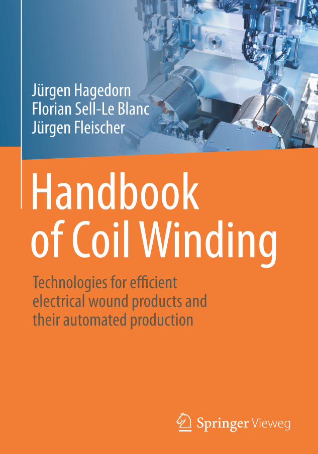
Handbook of Coil Winding Jürgen Hagedorn Florian Sell-Le Blanc Jürgen Fleischer Technologies for efficient electrical wound products and their automated production
Transcript of Jürgen Hagedorn Florian Sell-Le Blanc Jürgen Fleischer ...€¦ · Jürgen Hagedorn • Florian...
Handbook of Coil Winding
Jürgen HagedornFlorian Sell-Le BlancJürgen Fleischer
Technologies for efficient electrical wound products and their automated production
Handbook of Coil Winding
Jürgen Hagedorn • Florian Sell-Le Blanc • Jürgen Fleischer (Eds.)
Handbook of Coil WindingTechnologies for efficient electrical wound products and their automated production
EditorsJürgen HagedornAumann GmbHEspelkamp, Germany
Florian Sell-Le BlancAumann GmbHEspelkamp, Germany
Jürgen FleischerKarlsruher Institut für Technologiewbk Institut für Produktionstechnik,Karlsruhe, Germany
Additional material to this book can be downloaded from http://extras.springer.com. ISBN 978-3-662-54401-3 ISBN 978-3-662-54402-0 (eBook)DOI 10.1007/978-3-662-54402-0 ISBN 978-3-662-54403-7 (MyCopy)
© Springer-Verlag GmbH Germany 2018This work is subject to copyright. All rights are reserved by the Publisher, whether the whole or part
and retrieval, electronic adaptation, computer software, or by similar or dissimilar methodology now known or hereafter developed.The use of general descriptive names, registered names, trademarks, service marks, etc. in this publication does
laws and regulations and therefore free for general use.The publisher, the authors and the editors are safe to assume that the advice and information in this book are believed to be true and accurate at the date of publication. Neither the publisher nor the authors or the editors give a warranty, express or implied, with respect to the material contained herein or for any errors or omissions that may have been made.
Printed on acid-free paper
This Springer Vieweg imprint is published by Springer NatureThe registered company is Springer-Verlag GmbH GermanyThe registered company address is: Heidelberger Platz 3, 14197 Berlin, Germany
5
The requirement of energy efficiency for modern electrical devices is a key challenge in product development. In addition to electronic control approach, coil winding technology offers ways of fulfilling these requirements. This is the motivation behind the efforts to create a standard reference for coil winding technology.
Coils have been around for decades and they are used in a variety of applications, for example: ignition coils in passenger cars, magnet coils for valves, electric motors or induction stoves. Cheaper semiconductors enable coils to be used in electronic devices like smartphones, sensor coils on RFID chips or proximity sensors in automation technology. In the past, coil winding was a process performed by hand or using simple machines. Today, it is an interdisciplinary field combining material sciences, process technology, mechanical engineering and control as well as electrical engineering. The emerging products show high distribution and penetration in many areas of technology in our everyday life. Winding technology products can be found anywhere, ranging from home appliances to electronics and highly efficient motors for automation solutions, or mobile applications. This large variety of applications and the different boundary conditions results in various technologi-cal trends. Primarily, the increasing requirements for energy efficiency and efficiency rates of inductive components should be stated. As a consequence, products are constantly opti-mised to fulfil the requirements, exerting high demands on coil winding technology. Due to the growing electrification of consumer goods in homes, private and industrial areas, supported by cheap electronics, the products’ controllability is improved and losses can be reduced. This increases the significance of winding technology. With the first industrial implementation of coils, the methods, processes and machines initially used in the textile technology were applied to the production of coils. Until then, coils were often handmade in large factories. The requirements for winding technology were limited, because neither the products, like electric motors, nor the manufacturing itself were optimised. With the onset and the political acceleration of electro mobility motivated by the limitations of fossil fuels and resources, winding technology has risen in importance and has become a key expertise in electrical machine engineering. In the light of these developments, the
Preface
6 Preface
aim of this book is to provide an introduction to coil winding technology, describe the state of the art and help overcome the current challenges in the development of winding goods and production technology. Therefore, the target group consists of engineers, who design inductive products or production technology, develop electric motors or work in the field of production technology for motors. In education, this book can help mechatro-nics technicians or engineering students at university to understand winding technology. Employees in the areas of procurement or logistics for inductive production technology, and operators of winding machines can also benefit from the consolidated knowledge in this book. In terms of its content, this book first covers winding goods and their properties relevant to winding technology. As a key element of winding technology, the copper wire’s processing properties define process limits and the achievable product quality, and is the subject of the following chapter. The resulting automation solutions will then be presented based on the different types of windings and the available winding processes. Chapter 1 begins with an overview of the variety of inductive components, their applications and specifications, which will be described in their construction and design. The introduction of the properties relevant to the manufacturing of inductive components and a treatise of the use in electric motors with different winding patterns concludes this chapter. The structure, manufacturing and processing properties of copper wire are covered in Chap-ter 2. Chapter 3, which constitutes the core of this book, gives an introduction to winding processes as well as adjacent processes, such as connecting wires or assembling segments. As the final section of the book, Chapter 4 describes in detail the following processes with regard to the machine and control technology used. While referring to different levels of automation and respective production scenarios the technical implementation is illustra-ted by presenting common technical automation solutions. Following this, in the context of process control engineering, strategies for quality control and necessary testing tech-nology are presented with reference to critical component properties. Practical aspects of diagnosis and prognosis of process errors, as well as particularities of winding machines in terms of operation and maintenance are covered at the end.
In conclusion, the aim of this book is to provide insights into production oriented design and production of winding goods as well as adjacent processes for manufacturing inductive electronics and electrical machine construction.
7
Preface ............................................................................................................................................. 5
1. Introduction .......................................................................................................... 111.1 Introduction to coil winding technology ....................................................... 11
1.1.1 Definition of coil winding technology ........................................... 121.1.2 Delimitation of winding technology from other
manufacturing processes .................................................................. 131.1.3 Typical process chain for the production of winding goods ....... 15
1.2 Introduction to coil technology....................................................................... 181.2.1 Definition of coils .............................................................................. 191.2.2 Physical principles ............................................................................. 211.2.3 Coil types ............................................................................................ 361.2.4 Introduction to bobbins ................................................................... 411.2.5 Introduction to bobbin materials .................................................... 531.2.6 Coil design influences on manufacturing properties ................... 61
1.3 Introduction to electric motors ....................................................................... 681.3.1 Definition of electric motors ........................................................... 691.3.2 Functional principles of electric motors ........................................ 711.3.3 Applications of electric motors ....................................................... 791.3.4 General requirements for windings ................................................ 851.3.5 Concentrated windings for electric motors ................................... 861.3.6 Distributed windings for electric motors ....................................... 87
2. Enamelled copper wire .......................................................................................... 932.1 Conductor properties ....................................................................................... 93
2.1.1 Copper as an electrical conductor .................................................. 942.1.2 Other conductor materials ............................................................... 1002.1.3 Geometries of the conductor cross section and
conductor variants ............................................................................ 103
Table of contents
8 Table of contents
2.2 Process chain for conductor manufacturing using the example of enamelled copper wire ................................................................................. 1092.2.1 Process chain overview..................................................................... 1092.2.2 Drawing processes ............................................................................ 1122.2.3 Rolling process .................................................................................. 1152.2.4 Continuous annealing process ........................................................ 1162.2.5 Cleaning processes ............................................................................ 119
2.3 Conductor insulation ........................................................................................ 1212.3.1 Definition of insulation properties and testing procedures ........ 1222.3.2 Introduction to insulation materials............................................... 1252.3.3 Enamelling processes for insulation application ........................... 127
2.4 Use of lubricants ................................................................................................ 1332.4.1 Definition of lubricant properties ................................................... 1332.4.2 Introduction to lubricant materials ................................................ 1352.4.3 Processes for lubricant application ................................................. 135
3. Winding technology ............................................................................................ 1393.1 Basics of winding technology .......................................................................... 140
3.1.1 Physical basics ................................................................................... 1403.1.2 Introduction to winding schemes ................................................... 145
3.2 Central functions of winding technology ...................................................... 1603.2.1 Wire tension control ......................................................................... 1603.2.2 Balancing free wire lengths .............................................................. 165
3.3 Winding processes ............................................................................................ 1683.3.1 Introduction to winding processes ................................................. 1683.3.2 Machine elements of winding technology ..................................... 1713.3.3 Control technology for winding tasks ............................................ 1753.3.4 Linear winding technology .............................................................. 1783.3.5 Flyer winding technology ................................................................ 1913.3.6 Needle winding technology ............................................................. 1993.3.7 Toroidal winding technology........................................................... 2093.3.8 Insertion technology ......................................................................... 2113.3.9 Trickle winding or Fed-in winding ................................................. 2173.3.10 Selection methodology for winding processes .............................. 2213.3.11 Analysis of winding faults ................................................................ 224
3.4 Peripheral processes .......................................................................................... 2293.4.1 Preparing assembly processes .......................................................... 2293.4.2 Contacting processes ........................................................................ 2313.4.3 Bonding processes ............................................................................. 2333.4.4 Coil testing ......................................................................................... 2363.4.5 Subsequent assembly processes ....................................................... 2383.4.6 Secondary insulation ........................................................................ 239
Table of contents 9
4. Automation .......................................................................................................... 2454.1 Introduction ....................................................................................................... 245
4.1.1 Definition of automation.................................................................. 2464.1.2 Criteria for the degree of automation ............................................. 2494.1.3 Parameters for process automation ................................................ 2514.1.4 Different phases of automation ....................................................... 2574.1.5 Amortisation scenarios .................................................................... 259
4.2 Automation Concepts ....................................................................................... 2664.2.1 Industrial assembly concepts ........................................................... 2664.2.2 Conveying systems and layouts for manufacturing lines ............ 2704.2.3 Types of interlinkage for manufacturing lines .............................. 2764.2.4 Degrees of automation for winding machines .............................. 2784.2.5 Part properties relevant to automation .......................................... 279
4.3 Automation techniques .................................................................................... 2824.3.1 Common automation solutions ...................................................... 2824.3.2 Integration of manual workplaces .................................................. 286
4.4 Operation of automation .................................................................................. 2884.4.1 Quality control .................................................................................. 2884.4.2 Error susceptibility – process capability ......................................... 2904.4.3 Error diagnosis .................................................................................. 2944.4.4 Maintenance ...................................................................................... 2964.4.5 Requirements for operating ............................................................. 298
Index ...........................................................................................................................................301
1.1 Introduction to coil winding technology
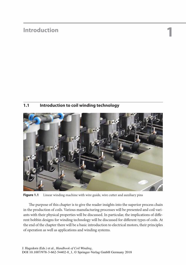
Figure 1.1 Linear winding machine with wire guide, wire cutter and auxiliary pins
The purpose of this chapter is to give the reader insights into the superior process chain in the production of coils. Various manufacturing processes will be presented and coil vari-ants with their physical properties will be discussed. In particular, the implications of diffe-rent bobbin designs for winding technology will be discussed for different types of coils. At the end of the chapter there will be a basic introduction to electrical motors, their principles of operation as well as applications and winding systems.
Introduction 1
J. Hagedorn (Eds.) et al., Handbook of Coil Winding, DOI 10.1007/978-3-662-54402-0_1, © Springer-Verlag GmbH Germany 2018
12 1 Introduction
The purpose of this section is to classify winding technology within manufacturing processes according to the German industry norm DIN 8580. It becomes clear that win-ding technology is an assembly process based on forming. The basic procedure of winding technology as part of a process sequence will be classified and key terms will be introduced.
This section provides a basic understanding of winding technology and coils.
1.1.1 Definition of coil winding technology
Coil winding technology means to wind an electrical conductor to a compact structure, a coil. Thereby, geometric structures develop by single or multiple windings, which may be layered in single or multiple layers. Coil applications can be divided into actuators, like electromagnets, electric motors and moving coils, as well as sensors, like antennas, microphones and other measuring devices. In both cases an electrical conductor, usually an enamelled copper wire, is wound onto a bobbin. The types of manufacturing range from bending of micro-technical coils with wire gauges of 12 μm to massive forming of conduc-tor skeins with several square centimeters cross section for power plant generators. The windings in electric motors can be found in the stator and, depending on the type of motor, also in the rotor and may consist of individual coils. Winding technology has an influence both on the electromagnetic design and in manufacturing, especially on the properties of wound electromagnetic components. Power density is a priority, which, depending on the application, can be traced back to the absorption or submission of a force, a field or a mag-netic flux. Other properties, such as insulation rigidity, must ensure the insulation rigidity of the component for a specific operating voltage. Since energy efficiency requirements are increasing rapidly, the development of electromechanical assemblies is becoming more and more challenging. Winding technology is divided into groups according to the type and geometry of the coils; these are presented in Sections 1.2.3 and 1.2.4. The winding process is part of a process chain and is always accompanied by upstream and downstream processes. The general process chain is described in Section 1.1.3. An introduction to com-mon upstream and downstream processes is given in Section 3.4. Section 1.2 provides an overview of different winding products with regard to the wire gauge used.
Introduction to coil winding technology 13
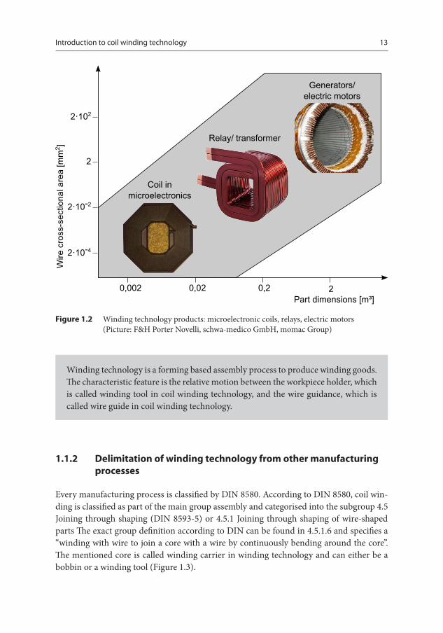
Figure 1.2 Winding technology products: microelectronic coils, relays, electric motors (Picture: F&H Porter Novelli, schwa-medico GmbH, momac Group)
Winding technology is a forming based assembly process to produce winding goods. The characteristic feature is the relative motion between the workpiece holder, which is called winding tool in coil winding technology, and the wire guidance, which is called wire guide in coil winding technology.
1.1.2 Delimitation of winding technology from other manufacturing processes
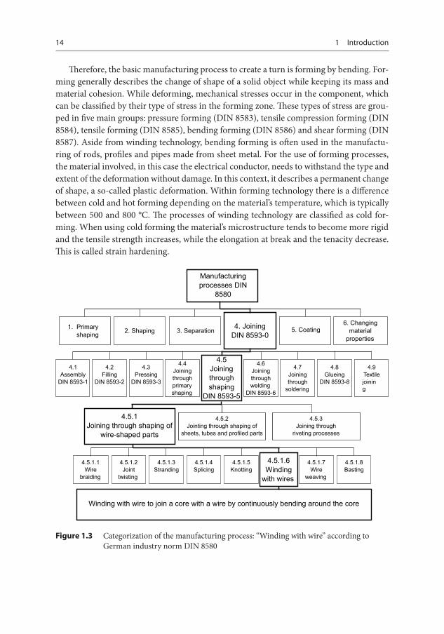
Every manufacturing process is classified by DIN 8580. According to DIN 8580, coil win-ding is classified as part of the main group assembly and categorised into the subgroup 4.5 Joining through shaping (DIN 8593-5) or 4.5.1 Joining through shaping of wire-shaped parts The exact group definition according to DIN can be found in 4.5.1.6 and specifies a “winding with wire to join a core with a wire by continuously bending around the core”. The mentioned core is called winding carrier in winding technology and can either be a bobbin or a winding tool (Figure 1.3).
14 1 Introduction
Therefore, the basic manufacturing process to create a turn is forming by bending. For-ming generally describes the change of shape of a solid object while keeping its mass and material cohesion. While deforming, mechanical stresses occur in the component, which can be classified by their type of stress in the forming zone. These types of stress are grou-ped in five main groups: pressure forming (DIN 8583), tensile compression forming (DIN 8584), tensile forming (DIN 8585), bending forming (DIN 8586) and shear forming (DIN 8587). Aside from winding technology, bending forming is often used in the manufactu-ring of rods, profiles and pipes made from sheet metal. For the use of forming processes, the material involved, in this case the electrical conductor, needs to withstand the type and extent of the deformation without damage. In this context, it describes a permanent change of shape, a so-called plastic deformation. Within forming technology there is a difference between cold and hot forming depending on the material’s temperature, which is typically between 500 and 800 °C. The processes of winding technology are classified as cold for-ming. When using cold forming the material’s microstructure tends to become more rigid and the tensile strength increases, while the elongation at break and the tenacity decrease. This is called strain hardening.
Manufacturingrocesses DIN
8580
1. Primaryhaping 2. Shaping 3. Separation
4. JoiningDIN 8593-0
5. Coating6. Changing
aterialroperties
4.4 Joiningthrough rimary haping
4.6 Joiningthrough
eldingDIN 8593-6
4.5 Joiningthroughhaping
DIN 8593-5
4.1 Assembly
DIN 8593-1
4.2 Filling
DIN 8593-2
4.3 Pressing
DIN 8593-3
4.7 Joiningthrough oldering
4.8 Glueing
DIN 8593-8
4.9 Textileoining
4.5.1 Joining through haping of
wire-shaped parts
4.5.2 Jointing through haping of
sheets, tubes and profiled parts
4.5.3 Joining through iveting processes
4.5.1.6Winding
with ires
4.5.1.1Wireraiding
4.5.1.2Joint
wisting
4.5.1.3Stranding
4.5.1.4Splicing
4.5.1.5Knotting
4.5.1.7Wire eaving
4.5.1.8Basting
Winding with wire to join a core with a wire by continuously bending around the core
Figure 1.3 Categorization of the manufacturing process: “Winding with wire” according to German industry norm DIN 8580
Introduction to coil winding technology 15
Therefore, the ability to change the shape of the conductor in coil winding technology is lower compared to hot forming and is also determined by the material used. The sur-face of the cold formed material remains smooth and the influence of the forming speed on the change of shape is low. The mechanical properties of the commonly used winding materials will be discussed in terms of their forming properties in the Sections 2.1.1 and 2.1.2. Wire winding has positioned itself as the most commonly used coil manufacturing process. However, depending on the application and the product design, coils may also be manufactured using different processes. In this context, primary forming processes for very small geometries, as they are used in micro-electronics, or separation processes for larger geometries for use in areas with high-power currents, should be mentioned. The main characteristic of primary forming processes is the transition of a formless object to a shaped one, as for example in casting. A detailed discussion of the application background is given in the section about coil types (Section 1.2.3).
Winding is only one of many manufacturing processes for the production of winding goods. The choice of a suitable process depends on the product design. However, since the winding process is the favored process for a great number of winding pro-ducts, the focus of this book is on this manufacturing process.
1.1.3 Typical process chain for the production of winding goods
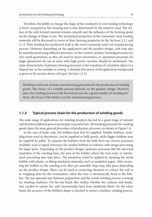
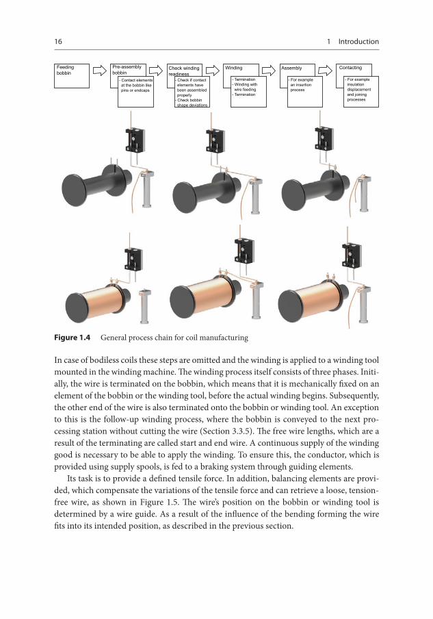
The wide range of applications for winding products has led to a great range of variants and therefore different process principles in production. All winding processes for winding goods share the same general procedure of production processes, as shown in Figure 1.4.
In the case of body coils, the bobbin must first be supplied. Smaller bobbins, inclu-ding those used in electronics, can be supplied as bulk goods, while bigger bobbins may be supplied by pallet. To separate the bobbins from the bulk there are various processes available, such as spiral conveyors for smaller bobbins or robotics with image processing for larger parts. Depending on the product design, upstream processes like the electrical insulation of the winding base, the area of the bobbin where the turn rests, or mecha-nical processing may take place. The insulation could be applied by spraying the metal bobbin with plastic, or fitting insulation materials, such as insulation paper. After moun-ting the bobbin on the winding tool other pre-assembly steps may take place depending on the product design. These can be used as contacting elements to contact the coil or as wrapping pins for the termination, when the wire is mechanically fixed to the bob-bin. The last optional step between preparation and the actual winding process is testing for winding readiness. On the one hand, this verifies whether the contacts and insula-tion needed to ensure the coil’s functionality have been faultlessly fitted. On the other hand, the accuracy of the bobbin’s shape is checked to ensure a faultless winding process.
16 1 Introduction
Feedingobbin
Pre-assemblybobbin
Check windingreadiness
Winding Assembly Contacting
- Contact elements at the bobbin like pins or endcaps
- Check if contact elements have been assembled properly- Check bobbin shape deviations
- Termination- Winding with wire feeding- Termination
- For example an insertion process
- For example insulation displacement and joining processes
Figure 1.4 General process chain for coil manufacturing
In case of bodiless coils these steps are omitted and the winding is applied to a winding tool mounted in the winding machine. The winding process itself consists of three phases. Initi-ally, the wire is terminated on the bobbin, which means that it is mechanically fixed on an element of the bobbin or the winding tool, before the actual winding begins. Subsequently, the other end of the wire is also terminated onto the bobbin or winding tool. An exception to this is the follow-up winding process, where the bobbin is conveyed to the next pro-cessing station without cutting the wire (Section 3.3.5). The free wire lengths, which are a result of the terminating are called start and end wire. A continuous supply of the winding good is necessary to be able to apply the winding. To ensure this, the conductor, which is provided using supply spools, is fed to a braking system through guiding elements.
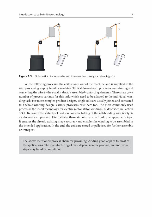
Its task is to provide a defined tensile force. In addition, balancing elements are provi-ded, which compensate the variations of the tensile force and can retrieve a loose, tension-free wire, as shown in Figure 1.5. The wire’s position on the bobbin or winding tool is determined by a wire guide. As a result of the influence of the bending forming the wire fits into its intended position, as described in the previous section.
Introduction to coil winding technology 17
Figure 1.5 Schematics of a loose wire and its correction through a balancing arm
For the following processes the coil is taken out of the machine and is supplied to the next processing step by hand or machine. Typical downstream processes are skinning and contacting the wire to the usually already assembled contacting elements. There are a great number of process variants for this task, which need to be adapted to the individual win-ding task. For more complex product designs, single coils are usually joined and contacted to a whole winding design. Various processes exist here too. The most commonly used process is the insert technology for electric motor stator windings, as described in Section 3.3.8. To ensure the stability of bodiless coils the baking of the self-bonding wire is a typi-cal downstream process. Alternatively, these air coils may be fixed or wrapped with tape. It ensures the already existing shape accuracy and enables the winding to be assembled in the intended application. In the end, the coils are stored or palletised for further assembly or transport.
The above mentioned process chain for providing winding good applies to most of the applications. The manufacturing of coils depends on the product, and individual steps may be added or left out.
18 1 Introduction
1.2 Introduction to coil technology
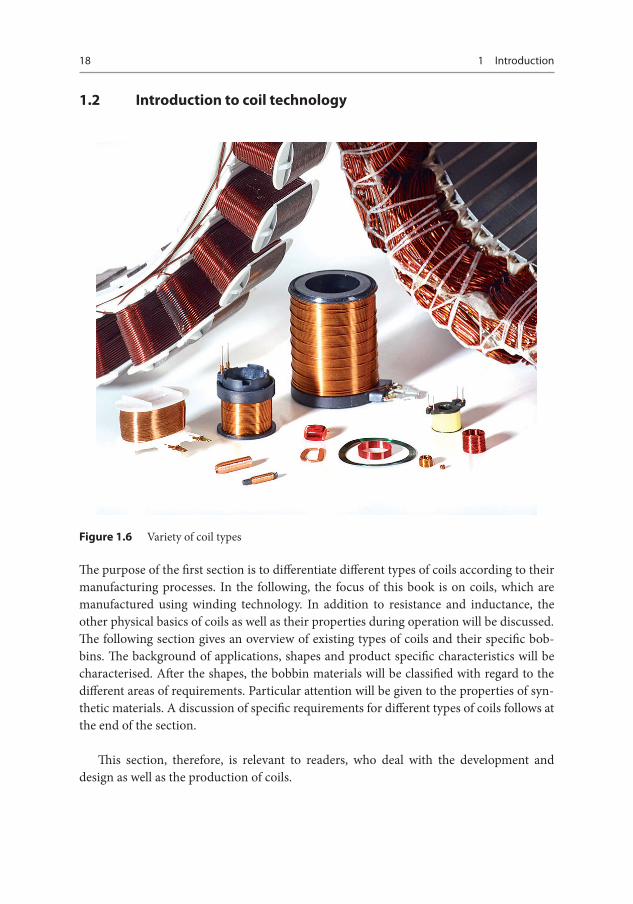
Figure 1.6 Variety of coil types
The purpose of the first section is to differentiate different types of coils according to their manufacturing processes. In the following, the focus of this book is on coils, which are manufactured using winding technology. In addition to resistance and inductance, the other physical basics of coils as well as their properties during operation will be discussed. The following section gives an overview of existing types of coils and their specific bob-bins. The background of applications, shapes and product specific characteristics will be characterised. After the shapes, the bobbin materials will be classified with regard to the different areas of requirements. Particular attention will be given to the properties of syn-thetic materials. A discussion of specific requirements for different types of coils follows at the end of the section.
This section, therefore, is relevant to readers, who deal with the development and design as well as the production of coils.
Introduction to coil technology 19
1.2.1 Definition of coils
Coils are geometric structures consisting of one or multiple electrically insulated conduc-tors, which generate an electric field when a current flows, or detect a magnetic field by measuring an induced voltage. This geometric structure is called winding and can be crea-ted with different geometries and different schemes. A detailed introduction to these sche-mes is given in Section 3.1.2. The conductor is usually made from copper, although other materials may be used (Sections 2.1.1 and 2.1.2). This conductor is mounted to a winding carrier. For air coils this is the winding tool, while for body coils a bobbin is used (Section 1.2.4). As for the manufacturing processes, the production of the conductor differs depen-ding on the type of coil, as described in Section 1.1.2. For the manufacturing of coils a variety of processes may be used; these are shown in Table 1.1. Besides typical coil winding technology there are other manufacturing processes, which may be suitable for production depending on the type and shape of the coil. Currently, the state of research is investigating the suitability of various primary forming coil manufacturing processes as an alternative to the winding process. For compact motor coils, which need to be manufactured very closely to the desired final shape, Fraunhofer IAM is investigating coil casting [Gro-14]. The advantage of manufacturing using primary forming is the low material stress during the production process and the ability to manufacture the parts very closely to the desired final shape. However, the winding carrier must be designed to enable collision-free assem-bly. Another primary forming process is already used today for coils in micro-electronics.
Coils manufactured using screen printing are most often used for sensory applica-tions or RFID chips (radio-frequency identification), a detection mechanism based on radio-frequencies. Approaches like printing motor coils have also been tested in research [Bra-12]. Mass production of coils for applications in entertainment and communication electronics is based on a separation process from the fourth main group in DIN 8085.
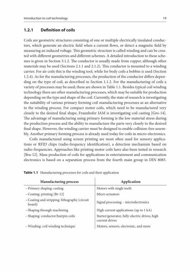
Table 1.1 Manufacturing processes for coils and their application
Manufacturing process Application – Primary shaping: casting Motors with single teeth – Coating: printing [Br-12] Micro actuators – Coating and stripping: lithography (circuit board) Signal processing – microelectronics
– Shaping through machining High current applications (up to 1 kA) – Shaping: conductor/hairpin coils Starter/generator, fully-electric drives, high
current drives – Winding: coil winding technique Motors, sensors, electronic, and more
20 1 Introduction
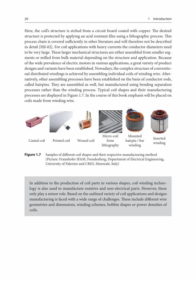
Here, the coil’s structure is etched from a circuit board coated with copper. The desired structure is protected by applying an acid resistant film using a lithographic process. This process chain is covered sufficiently in other literature and will therefore not be described in detail [Hil-02]. For coil applications with heavy currents the conductor diameters need to be very large. These larger mechanical structures are either assembled from smaller seg-ments or milled from bulk material depending on the structure and application. Because of the wide prevalence of electric motors in various applications, a great variety of product designs and variants have been established. Nowadays, the complex structure of conventio-nal distributed windings is achieved by assembling individual coils of winding wire. Alter-natively, other assembling processes have been established on the basis of conductor rods, called hairpins. They are assembled as well, but manufactured using bending separation processes rather than the winding process. Typical coil shapes and their manufacturing processes are displayed in Figure 1.7. In the course of this book emphasis will be placed on coils made from winding wire.
Casted coil Printed coil Wound coilMicro-coil
from lithography
Mounted hairpin / bar
winding
Inserted winding
Figure 1.7 Samples of different coil shapes and their respective manufacturing method (Picture: Fraunhofer IFAM, Freudenberg, Department of Electrical Engineering, University of Palermo and CRES, Monreale, Italy)
In addition to the production of coil parts in various shapes, coil winding techno-logy is also used to manufacture resistive and non-electrical parts. However, these only play a minor role. Based on the outlined variety of coil applications and designs manufacturing is faced with a wide range of challenges. These include different wire geometries and dimensions, winding schemes, bobbin shapes or power densities of coils.
Introduction to coil technology 21
1.2.2 Physical principles
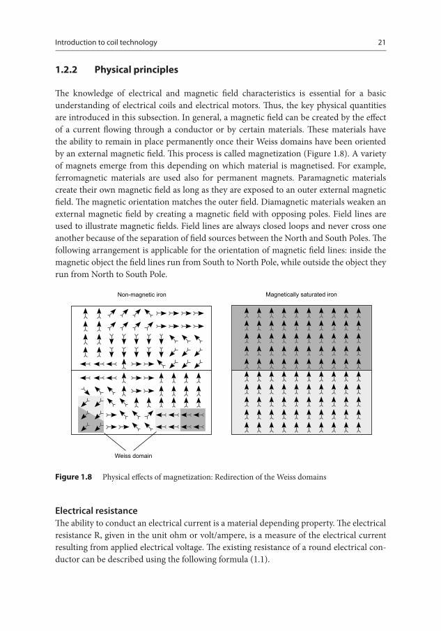
The knowledge of electrical and magnetic field characteristics is essential for a basic understanding of electrical coils and electrical motors. Thus, the key physical quantities are in troduced in this subsection. In general, a magnetic field can be created by the effect of a current flowing through a conductor or by certain materials. These materials have the ability to remain in place permanently once their Weiss domains have been oriented by an external magnetic field. This process is called magnetization (Figure 1.8). A variety of magnets emerge from this depending on which material is magnetised. For example, ferromagnetic materials are used also for permanent magnets. Paramagnetic materials create their own magnetic field as long as they are exposed to an outer external magnetic field. The magnetic orientation matches the outer field. Diamagnetic materials weaken an external magnetic field by creating a magnetic field with opposing poles. Field lines are used to illustrate magnetic fields. Field lines are always closed loops and never cross one another because of the separation of field sources between the North and South Poles. The following arrangement is applicable for the orientation of magnetic field lines: inside the magnetic object the field lines run from South to North Pole, while outside the object they run from North to South Pole.
Magnetically saturated ironNon-magnetic iron
Weiss domain
Figure 1.8 Physical effects of magnetization: Redirection of the Weiss domains
Electrical resistanceThe ability to conduct an electrical current is a material depending property. The electrical resistance R, given in the unit ohm or volt/ampere, is a measure of the electrical current resulting from applied electrical voltage. The existing resistance of a round electrical con-ductor can be described using the following formula (1.1).
22 1 Introduction
R = ρ · l
A= ρ · 4 · l
π · d2 (1.1)
ρ is the specific electrical resistance and is given in the unit Ω∙mm2/m. Furthermore, l stand for the length of the conductor and A for the cross sectional area. Assuming round wires for coils the cross sectional area can be substituted by the wire gauge.
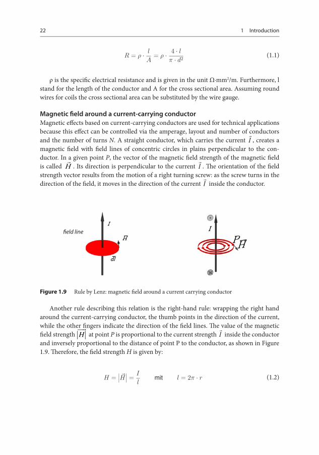
Magnetic field around a current-carrying conductorMagnetic effects based on current-carrying conductors are used for technical applications because this effect can be controlled via the amperage, layout and number of conductors and the number of turns N. A straight conductor, which carries the current I , creates a magnetic field with field lines of concentric circles in plains perpendicular to the con-ductor. In a given point P, the vector of the magnetic field strength of the magnetic field is called H . Its direction is perpendicular to the current I . The orientation of the field strength vector results from the motion of a right turning screw: as the screw turns in the direction of the field, it moves in the direction of the current I inside the conductor.
Figure 1.9 Rule by Lenz: magnetic field around a current carrying conductor
Another rule describing this relation is the right-hand rule: wrapping the right hand around the current-carrying conductor, the thumb points in the direction of the current, while the other fingers indicate the direction of the field lines. The value of the magnetic field strength H at point P is proportional to the current strength I inside the conductor and inversely proportional to the distance of point P to the conductor, as shown in Figure 1.9. Therefore, the field strength H is given by:
H =∣∣∣ �H
∣∣∣ = I
lmit l = 2π · r (1.2)
field line
Introduction to coil technology 23
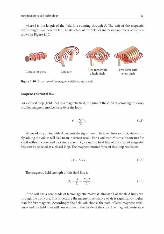
where l is the length of the field line running through P. The unit of the magnetic field strength is ampere/meter. The structure of the field for increasing numbers of turns is shown in Figure 1.10.
Conductor piece One turn Two turns with a high pitch
Five turns with a low pitch
Figure 1.10 Structure of the magnetic field around a coil
Ampere’s circuital law
For a closed loop (field line) in a magnetic field, the sum of the currents crossing this loop is called magneto motive force Θ of the loop:
Θ =∑n
In (1.3)
When adding up individual currents the signs have to be taken into account, since sim-ply adding the values will lead to an incorrect result. For a coil with N turns this means: for a coil without a core and carrying current I , a random field line of the created magnetic field can be selected as a closed loop. The magneto motive force of this loop results in:
Θ = N · I (1.4)
The magnetic field strength of this field line is
Hi = Θli
= N · I
li (1.5)
If the coil has a core made of ferromagnetic material, almost all of the field lines run through the iron core. This is because the magnetic resistance of air is significantly higher than for ferrimagnets. Accordingly, the field will choose the path of least magnetic resis-tance and the field lines will concentrate to the inside of the core. The magnetic resistance

24 1 Introduction
is also called reluctance and has the symbol RM. In this case the magnetic field strength in the core can be seen as almost homogenous and the average length of the field lines can be used to calculate the constant field strength:
H = Θlm
= N · I
lm (1.6)
The number of ampere-turns has established itself as a practical unit for the design and production of inductive components. This also represents the product of current and number of turns in a coil, and is therefore equivalent to the magneto-motive force.
Magnetic flux density or magnetic inductionA magnetic field is not fully described by the effect of the magnetic field strength. For a complete definition, another field parameter, magnetic flux B, often referred to as mag-netic induction, must be introduced.Its value is mainly defined by the properties of the medium in which the magnetic field is created. It runs in the same direction as the mag-netic field strength and is defined by multiplying with a material dependent constant, the magnetic permeability μ.
�B = μ · �H (1.7)
The permeability is the product of two values: – dimensioned permeability in vacuum μ0:
μ0 = 4π ∙ 10-7 Vs/Am
– dimensionless relative permeability of the material μr:
μ = μo · μr (1.8)
The unit for magnetic flux density is Tesla with 1 T = 1 Vs/m2. For non-magnetic mate-rials the approximation is μr = 1. For magnetic materials it is always μr > 1. Ferromagnetic materials can in theory reach μr of up to 106, but are effectively in the area of 103 or 104. However, for these materials the relative permeability is not constant, instead it depends on both the properties of the Weiss domains in the materials and the current magneto motive force. This is based on the physical dependencies of atoms, such as Block walls between the domains or phenomena like the Barkhausen effect, a discrete magnetization of the material caused by lattice imperfections.
Introduction to coil technology 25
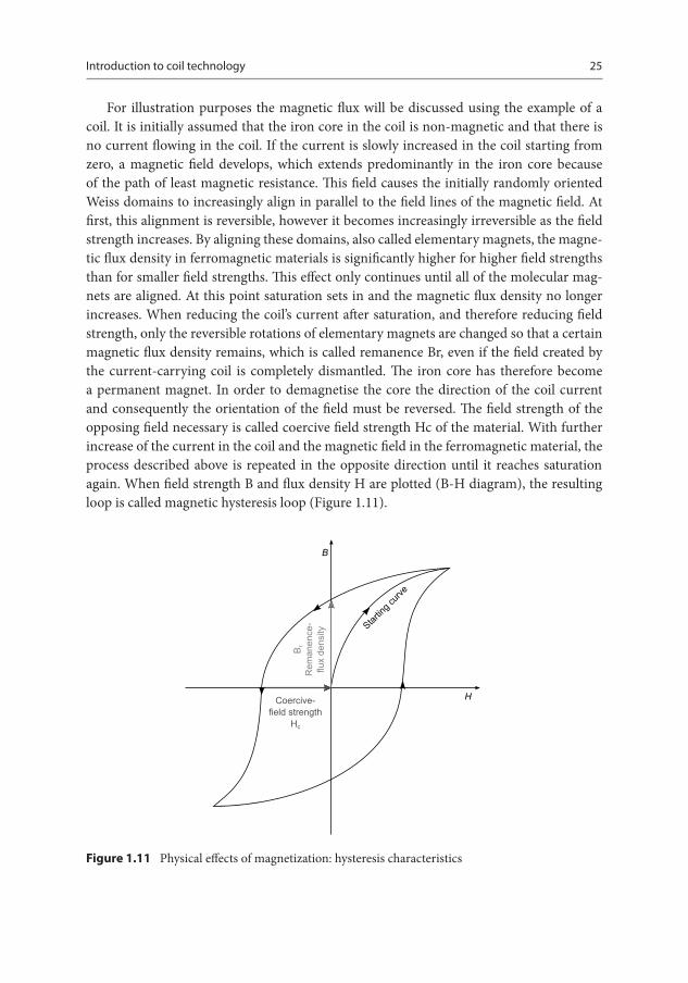
For illustration purposes the magnetic flux will be discussed using the example of a coil. It is initially assumed that the iron core in the coil is non-magnetic and that there is no current flowing in the coil. If the current is slowly increased in the coil starting from zero, a magnetic field develops, which extends predominantly in the iron core because of the path of least magnetic resistance. This field causes the initially randomly oriented Weiss domains to increasingly align in parallel to the field lines of the magnetic field. At first, this alignment is reversible, however it becomes increasingly irreversible as the field strength increases. By aligning these domains, also called elementary magnets, the magne-tic flux density in ferromagnetic materials is significantly higher for higher field strengths than for smaller field strengths. This effect only continues until all of the molecular mag-nets are aligned. At this point saturation sets in and the magnetic flux density no longer increases. When reducing the coil’s current after saturation, and therefore reducing field strength, only the reversible rotations of elementary magnets are changed so that a certain magnetic flux density remains, which is called remanence Br, even if the field created by the current-carrying coil is completely dismantled. The iron core has therefore become a permanent magnet. In order to demagnetise the core the direction of the coil current and consequently the orientation of the field must be reversed. The field strength of the opposing field necessary is called coercive field strength Hc of the material. With further increase of the current in the coil and the magnetic field in the ferromagnetic material, the process described above is repeated in the opposite direction until it reaches saturation again. When field strength B and flux density H are plotted (B-H diagram), the resulting loop is called magnetic hysteresis loop (Figure 1.11).
Figure 1.11 Physical effects of magnetization: hysteresis characteristics
26 1 Introduction
For coils used in applications with alternating current, this process takes place at 50 Hz, meaning 50 times per second. The friction of molecular magnets aligning inside the material causes losses, which are proportional to the core’s volume and the area of the hysteresis loop. For electrical machines and equipment (e.g. motors and transformers), in which the field lines run through sheeted metal structures these losses are undesirable for two reasons: firstly, because the efficiency decreases and secondly, because the compo-nents heat up. To counter this effect electromagnets, transformers and electric motors use magnetically soft materials, which have the smallest possible remanence and coercive field strength. This applies to so-called dynamo sheet metal (Fe with 3.75 % Si).
Permanent magnets, however, must have high remanence and high coercive field strength to protect against unwanted demagnetization by electrical stray fields. This is ensured by the use of so-called hard magnetic materials for permanent magnets. The har-dest magnetic materials, whose remanence is almost as high as their saturation flux density and whose coercive field strength almost reaches the saturation field strength are referred to as rectangular-hysteresis ferrites.
Magnetic fluxThe magnetic flux Φ is the unity of field lines emerging from one area and the field lines entering the opposing area. Here, A is the area occupied by the magnetic field, meaning the area where the magnetic flux spreads in the air gap. Therefore, flux density measures the flux in a certain area. Thus, flux equals flux density times area. For a homogenous magnetic field, the definition for magnetic flux is defined by pole area A, which is arranged perpen-dicularly to the flux direction:
Φ = B · A (1.9)
The unit for magnetic flux is Weber (volt-second) 1 Vs = 1 Weber = 1 Wb.
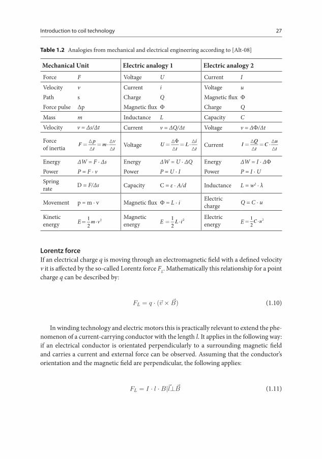
Analogies of mechanics and electrodynamicsFor a better comprehension of electrical and magnetic field phenomena analogies with mechanics are often used. A selection of such analogies is compiled in Table 1.2.
Introduction to coil technology 27
Table 1.2 Analogies from mechanical and electrical engineering according to [Alt-08]
Mechanical Unit Electric analogy 1 Electric analogy 2
Force F Voltage U Current IVelocity vPath sForce pulse Δp
Current iCharge QMagnetic flux Φ
Voltage uMagnetic flux ΦCharge Q
Mass m Inductance L Capacity CVelocity v = Δs/Δt Current v = ΔQ/Δt Voltage v = ΔΦ/Δt
Force of inertia
F=p
t= m
v
t
Voltage U =
t= L
i
t
Current I =
Q
t=C
u
t
Energy ΔW = F ∙ ΔsPower P = F ∙ v
Energy ΔW = U ∙ ΔQPower P = U ∙ I
Energy ΔW = I ∙ ΔΦPower P = I ∙ U
Spring rate D = F/Δs Capacity C = ε ∙ A/d Inductance L = w2 ∙ λ
Movement p = m ∙ v Magnetic flux Φ = L ∙ i Electric charge Q = C ∙ u
Kinetic energy E= 1
2m v2
Magnetic energy E =
1
2L i2
Electric energy E =
1
2C u2
Lorentz forceIf an electrical charge q is moving through an electromagnetic field with a defined velocity v it is affected by the so-called Lorentz force FL. Mathematically this relationship for a point charge q can be described by:
FL = q · (�v × �B) (1.10)
In winding technology and electric motors this is practically relevant to extend the phe-nomenon of a current-carrying conductor with the length l. It applies in the following way: if an electrical conductor is orientated perpendicularly to a surrounding magnetic field and carries a current and external force can be observed. Assuming that the conductor’s orientation and the magnetic field are perpendicular, the following applies:
FL = I · l · B|�l⊥ �B (1.11)
28 1 Introduction
This is often exemplified by using a conductor swing. If an electrically contacted con-ductor loop is located between the sides of a magnetic circle the conductor swing is deflec-ted towards the sides by the Lorentz force. Further and more detailed explanations can be found within the extensive literature on the nature of the Lorentz force.
Law of inductionWhen a constant magnetic flux penetrates a conductor loop with N turns, which is not carrying a current and is at rest, no forces are exerted on the electrons inside the conductor. However, if the magnetic flux changes, a current i(t) can be detected in the conductor loop, the size of which is proportional to the speed of change of the magnetic flux. The cause of this current must be a source of voltage Uq induced by the change in flux:
uq = N · dΦdt
(1.12)
Coil inductivityTo explain a coil’s self-inductance, an electrical coil with its conductors wound around a ring-shaped core made of non-magnetic synthetic material (ring coil) is examined. Since the non-magnetic synthetic material has almost the same permeability as a vacuum or air it may also be called air coil. The number of turns of the coil is N, the coil’s cross sectional area is A (cross sectional area of the core) and the average length of field lines is l. For a current changing over time i(t) the flow
Θ(t) = N · i(t) = H(t) · l (1.13)
is observed through the coil. Changing the current over time changes the flow over time. The magnetic flux is therefore
Φ(t) = B(t) · A = μ0 · H(t) · A = μ0 · N · i(t) · A
l. (1.14)
According to the law of induction the changing magnetic flux causes the induction of a voltage, which in turn causes a current to flow in the coil. This is called self-induction. The induced voltage is often 1 nH per
u(t) = N · dΦdt
= μ0 · N2 · A
l· di(t)
dt. (1.15)
Introduction to coil technology 29
It is therefore proportional to the coil current’s derivation over time. The factor of this proportionality depends on the number of turns N, the permeability μ0 and the dimensions of the coil. This factor, characteristic for self-inductance, is referred to as inductivity L:
L = μ0 · N2 · A
l. (1.16)
Inductivity, however, also depends on the design of the coil. For ring coils, for example, the length and diameter of the core are decisive. A distinction is made between the outer radius of the core R, the inner radius of the core r and the resulting core’s width or depth b. As an approximation the following equation can be used:
L = μ0 · μr · N2 · b
2πln R
r. (1.17)
For air gaps in the shape of cylinders, which have at least a 0.6-fold length to the radius rw, the following approximation is valid:
L = μ0 · N2 · A
l + 2 · rw/2, 2 . (1.18)
For practical purposes other characteristics like the induction constant AL, are often suitable because pre-manufactured cores are used. The unit of this characteristic value is often nH per square turn, which complies with reciprocal of the magnetic resistance. The inductivity is defined as follows, but is only valid for the linear part of the magnetic flux without saturation:
L = AL · N2. (1.19)
Consequently, the following correlation exists for current and voltage of a coil
u(t) = L · di(t)dt
. (1.20)
The inductivity’s unit is 1 Henry = 1 Vs/A = 1 Ωs (1 H).
An elongated rectangle is used as a circuit symbol for coils. However, in contrast to the circuit symbol for an electrical resistance it is filled in black. A real coil is always made from conductor wire, so that it always has an electrical resistance. Often a stylised coil is used as
30 1 Introduction
the circuit symbol for a real coil or, in the equivalent circuit diagram, a series connection of an ideal coil and an electrical resistance. The voltage drop in a real coil is therefore:
u(t) = uR(t) + uL(t) = R · i(t) + L · di(t)dt
. (1.21)
Electrical power losses in coilsThe power losses PCu in a coil depend primarily on the electrical resistance and can there-fore be described as [Wic-00]:
PCu = I2 · RCu = J2 · A2Cu · ρCu · lCu
ACu= J · ACu · ρCu · n · lm
PCu = J · I · n · ρCu · lm = J · Θ · ρCu · lm (1.22)
Here, the current density J describes the current divided by the conductor’s cross sec-tional area ACu. The value lm describes the average length of the conductor per turn, which gives the total conductor length when combined with the number of turns. However, this formula applies for flux density
PCu = n · I = J · ACu · n = J · kCu · AW bzw. AW = ΘJ · kCu
. (1.23)
In the last expression further parameters are introduced. kCu is a key characteristic in winding technology and describes the ratio between the area of the copper wire and the available winding area. The cross sectional area of the complete winding including gaps is described by the parameter Aw. The last unknown parameter in the power loss equation is the average wire length lm. For a non-circular coil core it can be expressed with the following equation, where b and t are the bobbin’s width and depth, and bw describes the winding width:
lm = 2 · (b + t + 2 · bw) = 2 · (b + t + 2 · AW
hW) = 2 · (b + t + 2 · 2 · Θ
hW · J · kCu). (1.24)
Introduction to coil technology 31
Using this relationship the power loss can be expressed as:
PCu = J · Θ · ρCu · 2 · (b + t + 2 · ΘhW · J · kCu
). (1.25)
Electrical losses in coils therefore depend on two general aspects. Outside the brackets are current density, magnetic flux and electrical conductivity. All of these quantities corre-spond to boundary conditions of the application, like current and number of turns as well as the choice of conductor material and the wire cross sectional area depending on the cur-rent density. The following term is primarily defined by the coil’s shape and the fill factor, which is why it can be more strongly affected by manufacturing and winding technology.
Magnetic energy of a coil (air coil)The magnetic energy of a coil equals the electrical work while building the magnetic field:
dWm = dWel = u(t) · i(t) · dt = L · di
dt· i(t) · dt = L · i · di. (1.26)
Thus
Wm = L ·∫
i · di = 12 · L · I2. (1.27)
Calculating the magnetic energy for iron coils, however, is more complex, because the coil’s inductance L is significantly larger than for air coils, but it depends on the current i(t) like the permeability μ.
Magnetic circuitsA closed field line in a magnetic field can also be called magnetic circuit, due to the analogy to an electrical circuit. The source of any electrical current, the voltage Uq, is compared to the magneto motive force Θ seen as the source of the magnetic field and is therefore also referred to as magnetic potential difference. The electrical conductivity κ = 1/ρ equates to the permeability μ = μ0 ∙ μr in magnetic circuits, so that the electrical resistance R = L/(κ ∙ A) compares to the magnetic resistance in the core RM = lm/(μ ∙ A).
The effect of the electrical voltage in an electrical circuit is an electrical current I = Uq/R, while the effect of the magnetic voltage is the magnetic flux Φ = Θ/RM. Consequently, ana-logue to the current density S = dI/dA in electrical circuits, there is magnetic flux density in magnetic circuits
B = dΘdA
. (1.28)