JP 3GB C.S0007 Direct Spread Specification for Spread ... · Direct Spread Specification for Spread...
132
JP- 3GB- C.S0007 Direct Spread Specification for Spread Spectrum Systems on ANSI-41 (DS-41) (Upper Layers Air Interface) Version 2 October 25, 2000 THE TELECOMMUNICATION TECHNOLOGY COMMITTEE
Transcript of JP 3GB C.S0007 Direct Spread Specification for Spread ... · Direct Spread Specification for Spread...

JP 3GB C.S0007
Direct Spread Specification for Spread Spectrum Systems
on ANSI-41 (DS-41) (Upper Layers Air Interface)
Version 2
October 25, 2000
THE TELECOMMUNICATION TECHNOLOGY COMMITTEE

i JP-3GB-C.S0007-0
JP-3GB-C.S0007Direct Spread Specification for Spread Spectrum Systems on ANSI-41 (DS-41)Upper Layers Air Interface
Remarks
1.Application level of English descriptionApplication level:E3
English description is included in the text and figures of main body, annexes and appendices.
2.Relationship with international recommendations and standardsThis standard is standardized based on the Technical Specification C.S0007-0 approved by 3GPP2 in July. 2000.
3.Departures from international recommendations3.1 Selection of optional items
None
3.2 Items of national matter
Analog and its related descriptions are either ignored or deleted from the document, since an analog system is not
considered in Japan.
3.3 Changes to original standard
(1) Standards referred to in the original standard, which are replaced by TTC/ARIB standards.
Refer to Table 1.
(2) Items added to the original standard
None
(3) Items deleted from the original standard
None
(4) Items changed from the original standard
None
3.4 Difference in chapter ordering from the original standard.
There is no difference in chapter ordering from the original standard.
4.Change history
Revision Date Contents
V.1 Mar.31,2000 Newly standardized
V.2 Oct.25,2000 Revised based on C.S0007-0 approved by 3GPP2 SC
in 2000. July.
5.IPRThere is no specific description about IPR in this standard.
6.OthersNone
ii JP-3GB-C.S0007-0
Table 1 Replaced standards referred
original standard replacement
3GPP TS 25.301
Title : Radio Interface Protocol Architecture
ARIB STANDARDS ARIB STD T63-25.301
3GPP TS 25.303
Title : Interlayer Procedures in Connected Mode
ARIB STANDARDS ARIB STD T63-25.303
3GPP TS 25.304
Title : UE Procedures in Idle Mode
ARIB STANDARDS ARIB STD T63-25.304
3GPP TS 25.322
Title : RLC Protocol Specification
TTC STANDARDS JP-3GA-25.322
3GPP TS 25.324
Title : Description of the Broadcast/Multicast Control
BMC protocol
TTC STANDARDS JP-3GA-25.324
3GPP TS 25.331
Title : RRC Protocol Specification
TTC STANDARDS JP-3GA-25.331
3GPP2 C.S0004-A
Title : Signaling Link Access Control (LAC)
Specification for cdma2000 Spread Spectrum Systems
TTC STANDARDS JP-3GB-C.S0004-A
3GPP2 C.S0005-A
Title : Upper Layer (Layer 3) Signaling Standard for
cdma2000 Spread Spectrum Systems
TTC STANDARDS JP-3GB-C.S0005-A
3GPP2 C.S0023-0
Title : Removable User Identity Module (R-UIM) for
Spread Spectrum Systems
ARIB STANDARDS ARIB STD T64-C.S0023-0
3GPP TS 23.110
Title : UMTS Access Stratum Services and Functions
TTC STANDARDS JP-3GA-23.110
Title : UMTS Access Stratum Services and Functions
3GPP TS 25.101
Title : UE Radio transmission and reception (FDD)
ARIB STANDARDS ARIB STD T63-25.101
3GPP TS 25.103
Title : RF parameters in support of RRM
TTC STANDARDS JP-3GA-25.103
3GPP TS 25.104
Title : BTS Radio transmission and reception (FDD)
ARIB STANDARDS ARIB STD T63-25.104
3GPP TS 25.201
Title : Physical layer -General Description
ARIB STANDARDS ARIB STD T63-25.201
3GPP TS 25.211
Title : Physical channels and mapping of transport
channels onto physical channels (FDD)
ARIB STANDARDS ARIB STD T63-25.211
3GPP TS 25.212
Title : Multiplexing and channel coding (FDD)
ARIB STANDARDS ARIB STD T63-25.212
3GPP TS 25.213
Title : Spreading and modulation (FDD)
ARIB STANDARDS ARIB STD T63-25.213
3GPP TS 25.214
Title : FDD; physical layer procedures
ARIB STANDARDS ARIB STD T63-25.214
3GPP TS 25.321
Title : MAC Protocol Specification
ARIB STANDARDS ARIB STD T63-25.321

iii JP-3GB-C.S0007-0
3GPP TR 25.990
Title : Vocabulary for UTRAN
ARIB TECHNICAL DOCUMENT ARIB TR T12-25.990
3GPP TR 25.925
Title : Radio Interface for Broadcast/Multicast Services
ARIB TECHNICAL DOCUMENT ARIB TR T12-25.925
TIA/EIA IS-637-A
Title : Short Message Service for Spread Spectrum
Systems
ARIB STANDARDS ARIB STD T64-C.S0015-0
3GPP2 C.S0007-0
Date: June 9, 2000
Direct Spread Specification for Spread Spectrum Systemson ANSI-41 (DS-41) (Upper Layers Air Interface)
COPYRIGHT
3GPP2 and its Organizational Partners claim copyright in this document and individualOrganizational Partners may copyright and issue documents or standards publications inindividual Organizational Partner's name based on this document. Requests forreproduction of this document should be directed to the 3GPP2 Secretariat [email protected]. Requests to reproduce individual Organizational Partner'sdocuments should be directed to that Organizational Partner. See www.3gpp2.org for moreinformation.

© 2000 3GPP2.
Intentionally left blank.

3GPP2 C.S0007-0
CONTENTS
i
Foreword ....................................................................................................................... viii 1
Notes............................................................................................................................... ix 2
References........................................................................................................................ x 3
1 Introduction ..........................................................................................................1-1 4
1.1 Scope....................................................................................................................1-1 5
1.2 Vocabulary and Terms ..........................................................................................1-1 6
1.3 Protocol Architecture for the DS-41 System ...........................................................1-5 7
1.4 Organization of the DS-41 Specifications ...............................................................1-7 8
1.5 General Overview of DS-41 Signaling.....................................................................1-7 9
1.5.1 System Information Broadcast .........................................................................1-8 10
1.5.2 Paging.............................................................................................................1-9 11
1.5.3 Cell Selection/Reselection................................................................................1-9 12
1.5.4 RRC Connection Maintenance........................................................................ 1-10 13
1.5.5 Handoff ......................................................................................................... 1-10 14
1.5.6 General Messaging ........................................................................................ 1-12 15
1.5.7 Call Processing .............................................................................................. 1-12 16
1.5.8 Mobility Management .................................................................................... 1-14 17
1.5.8.1 Registration and Location Update............................................................. 1-15 18
1.5.8.2 Security................................................................................................... 1-15 19
1.5.9 Broadcast SMS.............................................................................................. 1-15 20
1.6 Modeling............................................................................................................. 1-16 21
1.6.1 Logical Channels and SAPs............................................................................ 1-16 22
1.6.2 State Machines.............................................................................................. 1-17 23
1.6.2.1 Separation Between RRC and Call Control................................................ 1-17 24
1.6.2.2 Calls, Connections and Services ............................................................... 1-17 25
1.6.2.3 States and Transitions in the Mobile Station............................................. 1-17 26
2 Requirements for DS-41 Mobile Stations ................................................................2-1 27
2.1 Signaling Between the Mobile Station and the Base Station....................................2-1 28
2.1.1 Sending Upper Layers-related Information to the Base Station..........................2-1 29
2.1.2 Receiving Upper Layers-related Information from the Base Station...................2-1 30
2.2 Procedures............................................................................................................2-2 31

3GPP2 C.S0007-0
CONTENTS
ii
2.2.1 Broadcast System Information Processing........................................................ 2-3 1
2.2.2 General Order and Message Processing............................................................ 2-4 2
2.2.3 Call Processing................................................................................................ 2-6 3
2.2.3.1 Call Setup for Mobile Station-originated Calls ............................................ 2-7 4
2.2.3.2 Call Setup for Mobile Station-terminated Calls ........................................... 2-7 5
2.2.3.3 Signaling During a Call.............................................................................. 2-9 6
2.2.3.4 Call Clearing ........................................................................................... 2-10 7
2.2.4 Mobility Management Services Processing...................................................... 2-10 8
2.2.4.1 Authentication and Ciphering .................................................................. 2-11 9
2.2.4.2 Global Challenge ..................................................................................... 2-11 10
2.2.4.3 Encryption .............................................................................................. 2-11 11
2.2.4.4 Extended-Encryption............................................................................... 2-12 12
2.2.5 Support for Removable User Identity Module (R-UIM)..................................... 2-12 13
2.2.6 Mobile Station Identity and Characteristics.................................................... 2-12 14
2.2.7 Reception of Broadcast SMS.......................................................................... 2-12 15
2.3 Messages Sent by the Mobile Station................................................................... 2-12 16
2.3.1 DS-41 Modifications to Layer 3 PDUs Described in [5] .................................... 2-14 17
2.3.1.1 Security Mode Request Message ............................................................... 2-14 18
2.3.2 DS-41 Modifications to Information Records in [5].......................................... 2-14 19
2.3.3 Messages Specific to DS-41 Mode .................................................................. 2-15 20
2.3.3.1 DS-41 Call Start-up Message .................................................................... 2-15 21
2.3.3.2 DS-41 Registration Message ..................................................................... 2-23 22
2.3.3.3 DS-41 Release Message ........................................................................... 2-27 23
2.3.3.4 DS-41 Service Option Connect Complete Message....................................... 2-29 24
2.3.4 PDU Format.................................................................................................. 2-30 25
2.3.5 Timers and Constants ................................................................................... 2-32 26
3 Requirements for DS-41 Base Stations .................................................................. 3-1 27
3.1 Signaling Between the Base Station and the Mobile Station ................................... 3-1 28
3.1.1 Sending Upper Layers-related Information to the Mobile Station....................... 3-1 29
3.1.2 Receiving Upper Layers-related Information from the Mobile Station ............... 3-2 30
3.2 Procedures ........................................................................................................... 3-2 31
3.2.1 System Broadcast ........................................................................................... 3-3 32

3GPP2 C.S0007-0
CONTENTS
iii
3.2.2 Call Processing ................................................................................................3-3 1
3.2.2.1 Call Setup for Mobile Station-originated Calls .............................................3-3 2
3.2.2.2 Call Setup for Mobile Station-terminated Calls............................................3-4 3
3.2.2.3 Signaling During a Call ..............................................................................3-4 4
3.2.2.4 Call Clearing..............................................................................................3-5 5
3.2.3 Mobility Management Services Processing ........................................................3-5 6
3.2.4 Broadcast SMS................................................................................................3-5 7
3.3 Messages Sent by the Base Station........................................................................3-6 8
3.3.1 Modifications to Layer 3 PDUs Described in [5].................................................3-8 9
3.3.1.1 Sync Channel Message ...............................................................................3-8 10
3.3.1.2 ANSI-41 Systems Parameter Message ..........................................................3-8 11
3.3.1.3 ANSI-41 RAND Message..............................................................................3-8 12
3.3.1.4 User Zone Identification Message.................................................................3-8 13
3.3.1.5 Private Neighbor List Message .....................................................................3-8 14
3.3.1.6 Extended Global Service Redirection Message ..............................................3-8 15
3.3.1.7 Status Request Message .............................................................................3-8 16
3.3.1.8 Security Mode Command Message...............................................................3-9 17
3.3.1.9 Order Message ...........................................................................................3-9 18
3.3.1.10 Mobile Station Registered Message ............................................................3-9 19
3.3.2 DS-41 Modifications to Information Records Described in [5] ............................3-9 20
3.3.3 Messages Specific to DS-41 Mode................................................................... 3-12 21
3.3.3.1 DS-41 Call Request Message ..................................................................... 3-12 22
3.3.3.2 DS-41 In-traffic System Parameters Message ............................................. 3-14 23
3.3.3.3 DS-41 Release Message ............................................................................ 3-15 24
3.3.3.4 DS-41 Service Option Connect Message...................................................... 3-17 25
3.3.3.5 DS-41 Service Option Disconnect Message.................................................. 3-19 26
3.3.4 PDU Format .................................................................................................. 3-20 27
ANNEX A RESERVED .................................................................................................... 1 28
ANNEX B INFORMATION FLOWS ................................................................................... 1 29
B.1 Call Setup – Circuit-based Calls ............................................................................... 2 30
B.1.1 Mobile-originated Call Setup............................................................................... 2 31
B.1.2 Mobile-terminated Call Setup ............................................................................. 3 32

3GPP2 C.S0007-0
CONTENTS
iv
B.2 Call Clearing – Circuit-based Calls........................................................................... 5 1
B.2.1 MS-initiated Call Clearing – Circuit-based Call ................................................... 5 2
B.2.2 BS- and MSC-initiated Call Clearing – Circuit-based Call.................................... 6 3
B.2.3 PDSN-initiated Call Clearing – Packet Call .......................................................... 7 4
B.3 Short Message Service (SMS) ................................................................................... 8 5
B.3.1 Mobile-terminated Point-to-Point SMS................................................................ 8 6
B.3.2 Mobile-originated Point-to-Point SMS ................................................................. 9 7
B.3.3 Broadcast SMS.................................................................................................10 8
B.4 SSD Update ...........................................................................................................11 9
B.5 OTASP and OTAPA .................................................................................................13 10
B.6 Hard Handoff .........................................................................................................14 11
B.6.1 DS-41 to DS-41 Hard Handoff...........................................................................14 12
B.6.2 DS-41 to MC-41 Hard Handoff ..........................................................................16 13
B.6.3 DS-41 to Analog Hard Handoff ..........................................................................17 14
B.6.4 DS-41 to DS-41 – Inter-MSC Hard Handoff........................................................18 15
B.7 Packet Data Calls ...................................................................................................20 16
B.7.1 Origination and Packet Registration ..................................................................20 17
B.7.2 Entering Dormant State....................................................................................22 18
B.7.3 Packet Data Call Network Re-Activation.............................................................23 19
ANNEX C DS-41 SUPPORT IN [5] ................................................................................... 1 20
C.1 Procedures.............................................................................................................. 1 21
C.2 DS-41 Inter-system Transfer Message ....................................................................... 1 22
C.3 Service Redirection to DS-41 Systems...................................................................... 3 23
C.3.1 Changes to 3.7.2.3.2.16 of [5] ............................................................................ 3 24
C.3.2 Procedures ........................................................................................................ 3 25
C.4 Handoff to DS-41 Systems....................................................................................... 4 26
C.4.1 Idle Handoff to DS-41 Systems........................................................................... 4 27
C.4.1.1 DS-41 Addition to Universal Neighbor List Message in [5]............................... 5 28
C.4.2 Traffic Channel Measurements of DS ................................................................. 5 29
C.4.2.1 Addition to Candidate Frequency Search Request Message in [5] .................... 5 30
C.4.2.2 Addition to Candidate Frequency Search Report Message in [5] ...................... 6 31
C.4.2.2 Changes to 3.7.3.3.2.27 of [5]....................................................................... 7 32

3GPP2 C.S0007-0
CONTENTS
v
C.5 Operating Mode ....................................................................................................... 8 1
C.5.1 Additions to the Definition of OP_MODE for the MS in 2.7.4.15 of [5]................... 8 2
C.5.2 Additions to the Definition of Operating Mode for the BS in 3.7.2.3.2.15 of [5] ..... 9 3
C.6 Data Burst Messages ............................................................................................... 9 4
C.6.1 Procedures......................................................................................................... 9 5
C.6.2 Message Definition ............................................................................................. 9 6
C.7 Additional DS_BLOB field in the Sync Channel Message of [5] ................................. 10 7
8

3GPP2 C.S0007-0
FIGURES
vi
Figure 1.3-1. DS-41 General Architecture: Control Plane............................................... 1-6 1
Figure 1.3-2. DS-41 General Architecture: User Plane ................................................... 1-6 2
Figure 1.5.7-1. Successful Origination ........................................................................ 1-14 3
Figure 1.5.7-2. Successful Termination....................................................................... 1-14 4
Figure 1.6.2.3-1. Call Control State Machines ............................................................. 1-19 5
Figure B.1.1-1. Mobile-originated Call Setup .................................................................... 2 6
Figure B.1.2-1. Mobile-terminated Call Setup................................................................... 4 7
Figure B.2.1-1. Mobile-initiated Call Clearing – Circuit-based Call .................................... 5 8
Figure B.2.2-1. BS- and MSC-initiated Call Clearing – Circuit-based Call.......................... 6 9
Figure B.2.3-1. PDSN-initiated Call Clearing – Packet Call................................................ 7 10
Figure B.3.1-1. Mobile-terminated Point-to-Point Short Message Service (SMS-MT) ........... 8 11
Figure B.3.2-1. Mobile-originated Point-to-Point Short Message Service (SMS-MO) ............ 9 12
Figure B.3.3-1. Cell Broadcast Short Message Service .....................................................10 13
Figure B.4-1. SSD Update in a DS-41 System .................................................................12 14
Figure B.5-1. OTASP and OTAPA Support .......................................................................13 15
Figure B.6.1-1. DS-41 to DS-41 Hard Handoff.................................................................15 16
Figure B.6.2-1. DS-41 to MC-41 Hard Handoff ................................................................16 17
Figure B.6.3-1. DS-41 to Analog Hard Handoff ................................................................17 18
Figure B.6.4.1. DS-41 to DS-41 Inter-MSC Hard Handoff ................................................19 19
Figure B.7.1-1. Packet Data – Mobile-originated Registration and Call Setup ...................21 20
Figure B.7.2-1. Packet Data – Call Enters Dormant State ................................................22 21
Figure B.7.3-1. Packet Data – Network Re-Activation.......................................................23 22
Table 3.7.3.3.2.27-2. SEARCH_MODE Types.................................................................... 7 23
24

3GPP2 C.S0007-0
TABLES
vii
Table 2.2.3.3-1. Activation Times for the DS-41 Service Option Connect Message .............2-9 1
Table 2.3.3.3-1. Release “Reason” Codes...................................................................... 2-28 2
Table 2.3.4-1. Identification of the Uplink Upper Layers Messages................................ 2-31 3
Table 3.3.3.4-1. Bitmask Index Assignment for Hard Handoff Procedures..................... 3-18 4
Table 3.3.4-1. Identification of the Downlink Upper Layers Messages (part 1 of 2)......... 3-22 5
Table 3.3.4-1. Identification of the Downlink Upper Layers Messages (part 2 of 2)......... 3-23 6
Table 3.3.4-2. Broadcast System Information .............................................................. 3-23 7
Table C.2-1. Radio Interface Types ................................................................................... 2 8
Table C.2-2. Core Networks Types .................................................................................... 2 9
Table 2.7.4.15-2. OP_MODE for P_REV_IN_USEs Greater Than Three ............................... 8 10
Table 3.7.2.3.2.15-4. Operating Mode for MOB_P_REV Greater Than Three ....................... 9 11
12

3GPP2 C.S0007-0
FOREWORD
viii
This specification describes changes to the cdma2000 family of standards which will permit 1
the IMT-2000 CDMA Direct Spread (DS) radio air interface to operate with the Call Control 2
and Mobility Management services provided by a TIA/EIA-41 core network. This 3
combination of capabilities is referred to as a “DS-41” system. 4
This document has the following organization: 5
1. Introduction. This section defines the terms and vocabulary used in this document, as 6
well as providing a general overview of a DS-41 system. 7
2. Requirements for DS-41 Mobile Stations. This section specifies requirements which 8
apply to mobile stations supporting the DS-41 operating mode. 9
3. Requirements for DS-41 Base Stations. This section specifies requirements which 10
apply to base stations supporting the DS-41 operating mode. 11
Annex A. Reserved. 12
Annex B. Information Flows. This informative annex provides sample information flow 13
diagrams which illustrate various call scenarios in a DS-41 system. 14
Annex C. DS-41 Support in [5]. This normative annex describes the changes that are 15
required to [5] to support DS-41 operation. 16

3GPP2 C.S0007-0
NOTES
ix
1. This specification uses the following verbal forms: “Shall” and “shall not” identify 1
requirements to be followed strictly to conform to the specification and from which 2
no deviation is permitted. “Should” and “should not” indicate that one of several 3
possibilities is recommended as particularly suitable, without mentioning or 4
excluding others; that a certain course of action is preferred but not necessarily 5
required; or that (in the negative form) a certain possibility or course of action is 6
discouraged but not prohibited. “May” and “need not” indicate a course of action 7
permissible within the limits of the specification. “Can” and “cannot” are used for 8
statements of possibility and capability, whether material, physical, or causal. 9
2. Footnotes appear at various points in this specification to elaborate and to further 10
clarify items discussed in the body of the specification. 11
3. Unless indicated otherwise, this document presents numbers in decimal form. 12
Binary numbers are distinguished in the text by the use of single quotation marks. 13
3GPP2 C.S0007-0
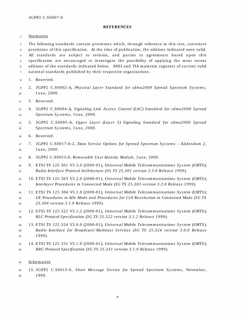
REFERENCES
x
Normative 1
The following standards contain provisions which, through reference in this text, constitute 2
provisions of this specification. At the time of publication, the editions indicated were valid. 3
All standards are subject to revision, and parties to agreements based upon this 4
specification are encouraged to investigate the possibility of applying the most recent 5
editions of the standards indicated below. ANSI and TIA maintain registers of current valid 6
national standards published by their respective organizations. 7
1. Reserved. 8
2. 3GPP2 C.S0002-A, Physical Layer Standard for cdma2000 Spread Spectrum Systems, 9
June, 2000. 10
3. Reserved. 11
4. 3GPP2 C.S0004-A, Signaling Link Access Control (LAC) Standard for cdma2000 Spread 12
Spectrum Systems, June, 2000. 13
5. 3GPP2 C.S0005-A, Upper Layer (Layer 3) Signaling Standard for cdma2000 Spread 14
Spectrum Systems, June, 2000. 15
6. Reserved. 16
7. 3GPP2 C.S0017-0-2, Data Service Options for Spread Spectrum Systems – Addendum 2, 17
June, 2000. 18
8. 3GPP2 C.S0023-0, Removable User Identity Module, June, 2000. 19
9. ETSI TS 125 301 V3.3.0 (2000-01), Universal Mobile Telecommunications System (UMTS); 20
Radio Interface Protocol Architecture (3G TS 25.301 version 3.3.0 Release 1999). 21
10. ETSI TS 125 303 V3.2.0 (2000-01), Universal Mobile Telecommunications System (UMTS); 22
Interlayer Procedures in Connected Mode (3G TS 25.303 version 3.2.0 Release 1999). 23
11. ETSI TS 125 304 V3.1.0 (2000-01), Universal Mobile Telecommunications System (UMTS); 24
UE Procedures in Idle Mode and Procedures for Cell Reselection in Connected Mode (3G TS 25
25.304 version 3.1.0 Release 1999). 26
12. ETSI TS 125 322 V3.1.2 (2000-01), Universal Mobile Telecommunications System (UMTS); 27
RLC Protocol Specification (3G TS 25.322 version 3.1.2 Release 1999). 28
13. ETSI TS 125 324 V3.0.0 (2000-01), Universal Mobile Telecommunications System (UMTS); 29
Radio Interface for Broadcast/Multicast Services (3G TS 25.324 version 3.0.0 Release 30
1999). 31
14. ETSI TS 125 331 V3.1.0 (2000-01), Universal Mobile Telecommunications System (UMTS); 32
RRC Protocol Specification (3G TS 25.331 version 3.1.0 Release 1999). 33
Informative 34
15. 3GPP2 C.S0015-0, Short Message Service for Spread Spectrum Systems, November, 35
1999. 36
3GPP2 C.S0007-0
REFERENCES
xi
16. 3GPP2 A.S0001, Inter-operability Specifications for cdma2000 Access Network Interfaces, 1
March, 2000. 2
17. 3GPP2 C.R1001-0, Parameter Value Assignments for cdma2000 Spread Spectrum 3
Systems, November, 1999. 4
18. ETSI TS 123 110 V3.3.0 (2000-01), Digital cellular telecommunications system (Phase 2+) 5
(GSM); Universal Mobile Telecommunications System (UMTS); UMTS Access Stratum 6
Services and Functions (3G TS 23.110 version 3.3.0 Release 1999). 7
19. ETSI TS 125 101 V3.1.0 (2000-01), Universal Mobile Telecommunications System (UMTS); 8
UE Radio transmission and Reception (FDD) (3G TS 25.101 version 3.1.0 Release 1999). 9
20. ETSI TS 125 104 V3.1.0 (2000-01), Universal Mobile Telecommunications System (UMTS); 10
UTRA (BS) FDD; Radio transmission and Reception (3G TS 25.104 version 3.1.0 Release 11
1999). 12
21. ETSI TS 125 201 V3.0.1 (2000-01), Universal Mobile Telecommunications System (UMTS); 13
Physical layer - General description (3G TS 25.201 version 3.0.1 Release 1999). 14
22. ETSI TS 125 211 V3.1.1 (2000-01), Universal Mobile Telecommunications System (UMTS); 15
Physical channels and mapping of transport channels onto physical channels (FDD) (3G TS 16
25.211 version 3.1.1 Release 1999). 17
23. ETSI TS 125 212 V3.1.1 (2000-01), Universal Mobile Telecommunications System (UMTS); 18
Multiplexing and channel coding (FDD) (3G TS 25.212 version 3.1.1 Release 1999). 19
24. ETSI TS 125 213 V3.1.1 (2000-01), Universal Mobile Telecommunications System (UMTS); 20
Spreading and modulation (FDD) (3G TS 23.213 version 3.1.1 Release 1999). 21
25. ETSI TS 125 214 V3.1.1 (2000-01), Universal Mobile Telecommunications System (UMTS); 22
Physical layer procedures (FDD) (3G TS 25.214 version 3.1.1 Release 1999). 23
26. ETSI TS 125 321 V3.2.0 (2000-01), Universal Mobile Telecommunications System (UMTS); 24
MAC protocol specification (3G TS 25.321 version 3.2.0 Release 1999). 25
27. ETSI TR 125 925 V3.0.0 (2000-01), Universal Mobile Telecommunications System (UMTS); 26
Radio Interface for Broadcast/Multicast Services (3G TR 25.925 version 3.0.0 Release 27
1999). 28
28. ETSI TR 125 990 V3.0.0 (2000-01), Universal Mobile Telecommunications System (UMTS); 29
Vocabulary (3G TS 25.990 version 3.0.0 Release 1999). 30
29. ANSI T1.607-1990, Integrated Services Digital Network (ISDN)–Layer 3 Signaling 31
Specification for Circuit Switched Bearer Service for Digital Subscriber Signaling System 32
Number 1 (DSS1), July, 1990. 33
30. TIA/EIA/IS-91, Mobile Station-Base Station Compatibility Standard for 800 MHz Analog 34
Cellular, October 1994. 35
31. TIA/EIA-95-B, Mobile Station-Base Station Compatibility Standard for Dual-Mode Spread 36
Spectrum Cellular System, November 1998. 37

3GPP2 C.S0007-0
xii
No text. 1

3GPP2 C.S0007-0
1-1
1 INTRODUCTION 1
1.1 Scope 2
This specification provides general requirements and detailed Upper Layers (Layer 3) 3
signaling protocols and procedures for the DS-41 radio interface. The protocols and 4
procedures address functionality that is customarily classified as pertaining to Call Control 5
and Mobility Management. Such functionality includes basic and supplementary services 6
provision, connection management, registration, security functions, identification of 7
subscriber equipment and its capabilities etc.; this functionality excludes the management 8
of radio resources, such as system selection and acquisition, channel allocation, release 9
and monitoring, RF measurement processing, handoff, and other related items. 10
The normative sections of this specification are stated in terms of requirements to be met by 11
infrastructure and by subscriber equipment that operate in DS-41 mode. The protocols 12
and procedures apply to the Upper Layers, as stated above. 13
Requirements for dual-mode DS-41/MC-41 systems, when operating in the MC-41 mode 14
and when executing a transition (e.g., handoff, service redirection) to the DS-41 mode are 15
given in Annex C. 16
Other documents (see 1.4) contain further requirements and/or capability descriptions 17
necessary for the procedures and protocols not covered by this specification. It is intended 18
that this specification, together with the accompanying documents, form a complete and 19
functional specification set for the DS-41 radio interface. 20
1.2 Vocabulary and Terms 21
In general, each document referenced by this specification contains sections on definitions 22
and abbreviations for locally used terms. [28] defines some of the vocabulary used in 3GPP 23
documents. 24
As a rule, the definitions and abbreviations present in the referenced documents are not 25
repeated within this text. The list below contains only definitions and abbreviations that 26
are considered essential for this specification; however, some terms are also provided for 27
clarity or provided as a convenience to the reader. The meaning of some terms is further 28
clarified when the usage in the 3GPP and 3GPP2 documents for the same or very similar 29
entity, functionality or concept is different or can be viewed as ambiguous. 30
3GPP. See Third Generation Partnership Project. 31
3GPP2. See Third Generation Partnership Project 2. 32
Access Stratum. 3GPP term used to identify the protocol layers directly involved in 33
interactions between infrastructure and subscriber equipment. Typically, it includes the 34
Radio Resource Control sublayer, Layer 2 and Layer 1. The corresponding 3GPP2 term is 35
“Lower Layers”. 36
3GPP2 C.S0007-0
1-2
Acknowledged mode. Term used in 3GPP specifications that refers to a delivery mode 1
which guarantees that a Protocol Data Unit (PDU) submitted by a transmitting entity will be 2
delivered to the peer receiving entity. The corresponding term used in 3GPP2 specifications 3
is “assured mode”. 4
AM. See Assured Mode. 5
AS. See Access Stratum. 6
Assured mode. Term used in 3GPP2 specifications that refers to a delivery mode which 7
guarantees that a Protocol Data Unit (PDU) submitted by a transmitting entity will be 8
delivered to the peer receiving entity. The corresponding term used in 3GPP specifications 9
is “acknowledged mode”. 10
Base Station. 3GPP2 term that refers generically to the infrastructure, as opposed to the 11
subscriber equipment. Depending on the context, “base station” may include, without 12
differentiating, the base station transceiver, the base station controller, the mobile 13
switching center, as well as other equipment. Depending on the context, the corresponding 14
3GPP terms can be “RAN”, “RNC” or “Node B”. 15
Base Station Controller. 3GPP2 term that refers to the part of the BS equipment that 16
interfaces with the core network, controls the radio transmitters and receivers at the BTS 17
and performs other radio access and link maintenance functions (such as soft handoff). 18
The corresponding 3GPP term is “RNC”. 19
Base Station System. Term used to describe a BSC and its associated BTSs. 20
Base Transceiver System. 3GPP2 term that refers to the infrastructure equipment that 21
performs radio transmissions, receptions and measurements, typically under the control of 22
a BSC. The corresponding 3GPP term is “Node B”. 23
BS. See Base Station. 24
BSC. See Base Station Controller. 25
BSS. See Base Station System. 26
BTS. See Base Transceiver Station. 27
Call Control. Generic name for the Layer 3 entity that handles call setup, tear-down and 28
in-call signaling. Other functionality may also be supported. It is seen as part of the Upper 29
Layers (NAS). 30
CC. See Call Control. 31
cdma2000. Name of a suite of specifications developed by 3GPP2. Narrowly defined, it 32
refers only to the radio interface. Broadly defined, it also includes (in part or in total) core 33
network specifications (see TIA/EIA-41), A-interface specifications (see [16]), and 34
interconnection to Internet Protocol network specifications. See also “MC-41”. 35
Cross mode. Generic term for either the DS-41 or MC-MAP system. Each system is 36
characterized by Upper Layers (Non-Access Stratum) and Lower Layers (Access Stratum) 37
that are defined by different Third Generation Partnership Projects. See also “Native mode”. 38
3GPP2 C.S0007-0
1-3
Direct Spread. CDMA radio technology defined by 3GPP. One of the ITU-R recommended 1
IMT-2000 radio transmission technologies. See also “W-CDMA”. 2
DS. See Direct Spread. 3
DS-41. 3G system which uses the Upper Layers provided by the TIA/EIA-41 protocol and 4
the Lower Layers defined for the Direct Spread mode. 5
DS-MAP. 3G system which is based entirely on the suite of 3GPP specifications. 6
Handoff. 3GPP2 term used as a synonym for the 3GPP term “handover”. The act of 7
transferring communication with a mobile station from one base station to another. 8
Handover. 3GPP term used as a synonym for the 3GPP2 term “handoff”. 9
IMT-2000. A family of 3G systems and radio technology defined by the International 10
Telecommunications Union (ITU). 11
Lower Layers. 3GPP2 term used to identify the protocol layers and functionality directly 12
involved in interactions between the infrastructure and the subscriber equipment. 13
Typically these include the Radio Resource Control sublayer, Layer 2 and Layer 1. The 14
corresponding 3GPP term is “Access Stratum”. 15
MC. See Multi-Carrier. 16
MC-41. 3G system which is based entirely on the suite of 3GPP2 specifications. 17
MC-MAP. 3G system which uses the Upper Layers provided by the GSM-MAP protocol and 18
the Lower Layers defined for the Multi-Carrier mode. 19
MM. See Mobility Management. 20
Mobile Station. 3GPP2 term that refers to the subscriber equipment, as opposed to the 21
infrastructure. The corresponding 3GPP term is “UE”. 22
Mobility Management. Generic name for the Layer 3 entity responsible for registrations, 23
location updates, authentication functions and Layer 3 addressing. Other functionality 24
may also be supported. It is seen as part of the Upper Layers (NAS). 25
MS. See Mobile Station. 26
Multi-Carrier. CDMA radio technology defined by 3GPP2. One of the ITU-R recommended 27
IMT-2000 radio transmission technologies. See also “cdma2000”. 28
NAS. See Non-Access Stratum. 29
Native mode. Generic term for either the DS-MAP or MC-41 system. Each system is 30
characterized by Upper Layers (Non-Access Stratum) and Lower Layers (Access Stratum) 31
that are defined by the same Third Generation Partnership Project. See also “Cross mode”. 32
Non-Access Stratum. 3GPP term used to identify the protocol layers and functionality 33
related to the core network. Typically it includes the Call Control and Mobility Management 34
layers. The corresponding 3GPP2 term is “Upper Layers”. 35
Node B. 3GPP term that refers to UTRAN equipment which performs radio transmissions, 36
receptions and measurements, typically under the control of an RNC. The corresponding 37
3GPP2 term is “BTS”. 38
3GPP2 C.S0007-0
1-4
Radio Access Network. Term that generically refers to the part of the infrastructure that 1
is directly involved in radio communications with the subscriber equipment. The RAN 2
performs the radio functionality of the infrastructure, as well as the connection to the core 3
network. See also “Base Station”. The RAN typically includes a controller (RNC in 3GPP 4
and BSC in 3GPP2) and several transmitter/receivers (Node B in 3GPP, BTS in 3GPP2). 5
Radio Network Controller. 3GPP term that refers to UTRAN equipment which interfaces 6
with the core network, controls the radio transmitters and receivers in Node Bs and 7
performs other radio access and link maintenance functions (such as soft handoff). The 8
corresponding 3GPP2 term is “BSC”. 9
Radio Resource Control. Generic name for the Layer 3 entity that handles radio 10
dependent operations and handoffs. Other functionality may also be supported. It is seen 11
as part of the Lower Layers (AS). 12
RAN. See Radio Access Network. 13
RNC. See Radio Network Controller. 14
RRC. See Radio Resource Control. 15
Service Option. 3GPP2 term that refers to an identifier for a specific service. A service 16
option may specify a speech connection using a particular vocoding technique, a certain 17
type of traffic (such as Short Message Service), or a connection type (such as Internet 18
Protocol). 19
SO. See Service Option. 20
Third Generation Partnership Project. The organization responsible for developing 21
W-CDMA specifications. 22
Third Generation Partnership Project 2. The organization responsible for developing 23
cdma2000 specifications. 24
Transparent mode. Term used in 3GPP specifications that refers to a delivery mode in 25
which no protocol information is added by the lower layer in charge of the PDU delivery. In 26
the signaling plane, this mode may apply to broadcast. The 3GPP2 specifications view 27
transparent mode as a submode of the unassured mode. 28
UE. See User Equipment. 29
UM. See Unassured Mode. 30
UMTS. See Universal Mobile Telecommunications System. 31
Unacknowledged mode. Term used in 3GPP specifications that refers to a delivery mode 32
which does not guarantee that a PDU submitted by a transmitting entity will be delivered to 33
the peer receiving entity. The corresponding term used in the 3GPP2 specifications is 34
“unassured mode”. 35
Unassured mode. Term used in 3GPP2 specifications that refers to a delivery mode which 36
does not guarantee that a PDU submitted by a transmitting entity will be delivered to the 37
peer receiving entity. The corresponding term used in the 3GPP specifications is 38
“unacknowledged mode”. 39
3GPP2 C.S0007-0
1-5
Universal Mobile Telecommunications System. 3G system developed by 3GPP that 1
includes specifications for the core network, UTRAN, IP connections, and various radio 2
interfaces (including W-CDMA). 3
Upper Layers. 3GPP2 term used to identify the protocol layers and functionality related to 4
the core network. Typically these include the Call Control and Mobility Management layers. 5
The corresponding 3GPP term is “Non-Access Stratum”. 6
User Equipment. 3GPP term that refers to the subscriber equipment, as opposed to the 7
infrastructure. The UE may be seen as a mobile radio terminal containing a removable 8
user identity module, and may possibly be connected to an application platform (such as a 9
laptop computer). The corresponding 3GPP2 term is “MS”. 10
UTRAN. The RAN for UMTS systems. 11
W-CDMA. See Wideband CDMA. 12
Wideband CDMA. Name of a suite of specifications developed by 3GPP. Narrowly defined, 13
it refers only to the DS radio interface. Broadly defined, it also includes (in part or in total) 14
core network specifications (e.g., GSM-MAP), A-interface specifications (e.g., Iu), and 15
interconnection to Internet Protocol network specifications (e.g., GPRS). See also “DS-MAP” 16
and “UMTS”. 17
Note: The terms ITU, ITU-R, TIA/EIA, ETSI, GSM, ANSI, GSM-MAP, A-interface, CDMA, 3G, 18
are considered to be well-known; hence, no additional information is provided about these 19
familiar terms within the body of this specification. 20
1.3 Protocol Architecture for the DS-41 System 21
Figure 1.3-1 shows the general architecture for the Control Plane of DS-41 systems, and 22
Figure 1.3-2 shows the general architecture for the User Plane of DS-41 systems. 23

3GPP2 C.S0007-0
1-6
Layer 1CDMA-DS
Layer 2CDMA-DS
Layer 3 - RRCCDMA-DS
Layer 1CDMA-DS
Layer 2CDMA-DS
Layer 3 - RRCCDMA-DS
Transport
Packet ControlFunction (PCF)
Transport Transport
Packet Data ServiceNode (PDSN)
TransportInternetAccess
IOS
Transport Transport
A9A11
A1
Base Station (BS)[Radio Access Network (RAN)]
Mobile Station (MS)[User Equipment (UE)]
MSC and PDSN[Core Network (CN)]
ANSI-41IOS
MSC
L3 CC/MMcdma2000
L3 CC/MMcdma2000
DC GC Nt DC GC Nt
Service Access Points: DC = Dedicated Control SAP, GC = General Control SAP, Nt = Notification SAP
1
Figure 1.3-1. DS-41 General Architecture: Control Plane 2
3
L ayer 1CD M A -D S
L ayer 2CD M A -
D S
L ayer 1CD M A -D S
L 2CD M A -
D STransport
Packet Contro lFunction (PCF)
Transport Transport
Packet D ata ServiceN ode (PD SN )
TransportIn ternetA ccess
IO S
Transport Transport
A 8A 10
A 2
Base S tation (BS)[Radio A ccess N etw ork (RA N )]
M obile S tation (M S)[U ser Equipm ent (U E)]
M SC and PD SN[Core N etw ork (CN )]
A N SI-41IO S
M SC
V ocoderX C
PacketD ata
PacketD ata
4
Figure 1.3-2. DS-41 General Architecture: User Plane 5

3GPP2 C.S0007-0
1-7
1.4 Organization of the DS-41 Specifications 1
The radio interface portion of the DS-41 system is specified via a series of documents from 2
ETSI and TIA. 3
General Description and Requirements 4
This specification provides an overview of the radio interface of the DS-41 system, 5
as well as general requirements. 6
Upper Layers 7
The Call Control and Mobility Management protocols, as well as other Upper 8
Layers functionality, are specified in [5] and [4], and in this specification. 9
Access Stratum 10
A general description of the functionality covered by the Access Stratum is given 11
in [9]. 12
RRC 13
The Radio Resource Control protocols are specified in [14]. Radio Resource 14
Control procedures for operating in connected-mode are specified in [10]. Radio 15
Resource Control procedures for operating in idle mode are specified in [11]. 16
L2 17
Layer 2 procedures and protocols are specified in [26] (MAC) and [12] (RLC). 18
L1 19
Layer 1 is described in [21], [25], [19], [20], [22], [23] and [24]. 20
Parameter Value Assignments (for Upper Layers) 21
Service Option numbers and other values of interest are defined in [17]. 22
Removable User Identity Module (R-UIM) 23
The R-UIM is specified in [8]. 24
Quality of Service (QoS) 25
The QoS record for packet data services is specified in Chapter 12 of [7]. 26
Broadcast SMS 27
A description of the TIA/EIA-41 Short Message Service (including broadcast SMS) 28
can be found in [15]. [27] and [13] describe the radio interface for broadcast 29
services, including the Broadcast/Multicast Control (BMC). 30
1.5 General Overview of DS-41 Signaling 31
DS-41 signaling is based upon the W-CDMA signaling for the Lower Layers (Access 32
Stratum) and the cdma2000 signaling for the Upper Layers (Non-Access Stratum). The 33
documents identified in 1.4 provide comprehensive and detailed descriptions of all the 34
relevant procedures and protocols. This section provides only a brief summary of the DS-35
41 signaling needed to facilitate the understanding of this specification. The RAN 36
3GPP2 C.S0007-0
1-8
operations are separate from the core network operations. In signaling terms, the messages 1
employed by the RRC are separate from the Upper Layer messages. The RRC provides a 2
transport service to the Upper Layers by encapsulating the Upper Layer information in 3
System Information Blocks, information elements in RRC messages, or messages embedded 4
in RRC messages. 5
The Layer 3 signaling between the RAN and the mobile station is performed via messages 6
that are sent on channels. The channels can be logical channels, transport channels or 7
physical channels. Logical channels can be mapped (multiplexed) to one or more transport 8
channels; these channels, in turn, can be mapped to physical channels. From the 9
perspective of DS-41 signaling, the following logical channels are the most important:1 10
• BCCH, mapped to the BCH or FACH transport channels 11
• PCCH, mapped to the PCH transport channel 12
• CCCH, mapped to the RACH and FACH transport channels 13
• CTCH, mapped to the FACH transport channel 14
• DCCH, mapped to the RACH, FACH, or DCH transport channels 15
From the RAN perspective, a mobile station is either idle or connected. An idle mobile 16
station may monitor the BCH transport channel occasionally, but it will monitor the PCH 17
transport channel with some periodicity. The RAN may not be aware of the presence of the 18
mobile station in any particular location; thus, the determination of the exact timing when 19
a page must be sent, along with the addressing information necessary for the successful 20
paging of the mobile station, are the responsibility of the core networks. 21
When a mobile station is connected it has a (Layer 2) temporary RAN identifier (RNTI) that 22
is understood by both mobile station and RAN, but not by the core networks. In such 23
cases, the paging of the mobile station can be performed using the RNTI and using an exact 24
timing determined by the RAN. The RAN supports different levels of connectivity. In the 25
high connectivity states the mobile station continuously monitors the DCH or the FACH, 26
and it can immediately transmit on the DCH or RACH. In the lower states of connectivity, 27
the mobile station occasionally monitors the PCH transport channel with some periodicity 28
(known to the RAN); and, thus, it is necessary for the RAN to page the mobile station or it 29
is necessary for the mobile station to use the RACH transport channel for communications. 30
1.5.1 System Information Broadcast 31
System information is generally transmitted on the BCCH logical channel. The information 32
is organized in a hierarchical, tree-like manner, with different nodes containing various 33
pieces of information and scheduling information about their sub-nodes. In this manner, 34
the content and repetition time intervals of the broadcast information can be easily 35
controlled. From the DS-41 system perspective, the system information can be classified as 36
1 Other logical channels are also defined. Alternate logical-to-transport channel mappings are also possible.
3GPP2 C.S0007-0
1-9
RRC-related or core network-related, and is generally located in different system 1
information blocks. In addition, the broadcast function may be employed to support 2
various applications (e.g., tiered services, location services). Updates to the system 3
information related to the core network may be sent on the DCCH to mobile stations in the 4
connected mode via the DS-41 In-Traffic System Parameters Message (see 3.3.3.2). 5
1.5.2 Paging 6
A mobile station may be paged when it functions in idle mode with respect to the RAN, 7
when it monitors the PCH channel while connected to the RAN, or when it monitors a 8
DCCH logical channel mapped to the FACH transport channel. 9
In idle mode, the mobile station monitors the PCH transport channel, usually in DRX mode 10
(i.e., periodically), with a periodicity (DRX cycle length) known to the core network but 11
usually unknown to the RAN. If the mobile station is simultaneously registered with more 12
than one core network, the minimum (i.e., smallest period) DRX cycle length is used. The 13
page record will contain either the IMSI or the TMSI and will be sent on the PCCH logical 14
channel via a Paging Type 1 message. 15
If the mobile station is connected to the RAN, but is in a state in which it monitors the PCH, 16
the paging timing is controlled by a DRX cycle length known to the RAN and broadcast on 17
the BCCH.2 Since an RRC connection exists, it is possible to identify the mobile station by 18
RNTI, as well as by IMSI or TMSI. As in the case of the idle mode, the Paging Type 1 19
message is employed to carry the page. The Paging Type 1 message is also capable of 20
toggling the DRX mode and of notifying mobile stations regarding changes in the broadcast 21
system information. 22
If the mobile station operates on a DCCH logical channel mapped to a FACH transport 23
channel, the Paging Type 2 message is employed. The addressing is performed using either 24
IMSI or TMSI. 25
1.5.3 Cell Selection/Reselection 26
Since the RAN is functionally separated from the core network, changes in the cell upon 27
which the mobile station is camped result in separate actions for the RAN and for the core 28
network. The cell selection/reselection and cell update procedures are described in [11] 29
and [14]. For core network-related procedures, the mobile station must update the relevant 30
new system information (e.g., by monitoring the BCH channel) and decide, based upon the 31
core network registration information, if a new registration/location update to the core 32
network is warranted. Such registration must occur via an RRC connection. If a suitable 33
connection is not present, an RRC connection must be set up, to perform the registration-34
related procedures. See 1.5.8.1 for details. Annex C extends the Universal Neighbor List 35
Message, used on MC-41 systems, to facilitate idle handoff between MC-41 and DS-41 36
systems. 37
2 It is possible, in principle, for the RAN and/or the core network to define specific values for their respective DRX length cycles on a mobile station by mobile station basis.

3GPP2 C.S0007-0
1-10
1.5.4 RRC Connection Maintenance 1
This specification requires the existence of an RRC connection for signaling (with the 2
exception of system information broadcast, paging and SMS broadcast); if an RRC 3
connection does not exist, the mobile station attempts to establish one. 4
The mobile station sends an RRC CONNECTION REQUEST message to the RAN on the 5
CCCH logical channel, containing, among other information, the reason for the request 6
(“establishment cause”) and some minimal capability information necessary for the RAN to 7
continue the dialog with the mobile station. Normally, the RAN responds on the CCCH 8
logical channel with an RRC CONNECTION SETUP message, that establishes a bi-9
directional signaling bearer (DCCH logical channel) between the mobile station and the 10
RAN. The mobile station completes the sequence by sending an RRC CONNECTION SETUP 11
COMPLETE message (containing more detailed capability information necessary for further 12
operation) on the DCCH. If a signaling bearer cannot be granted, the connection request is 13
rejected via an RRC CONNECTION REJECT message and the mobile may be instructed to 14
retry the connection request after a waiting period. If several attempts are unsuccessful, 15
the mobile station stays in the idle state from the RAN perspective, but the upper layers are 16
notified of the failure and may direct the mobile station to a different, implementation-17
specific course of action. 18
Detailed mobile station capability information may be obtained at any time via the UE 19
CAPABILITY INFORMATION message that can be sent on the DCCH logical channel by the 20
mobile station either autonomously or in response to a UE CAPABILITY ENQUIRY message 21
received on the DCCH from the base station. Upon reception of the UE CAPABILITY 22
INFORMATION message, the base station replies with a UE CAPABILITY INFORMATION 23
CONFIRM message. 24
In case of RRC link failure, the mobile station may attempt to re-establish the RRC 25
connection by sending an RRC CONNECTION RE-ESTABLISHMENT REQUEST message, 26
containing the RNTI of the mobile station, on the RACH transport channel. If the RRC 27
connection can be re-established successfully, the RAN will reply with an RRC 28
CONNECTION RE-ESTABLISHMENT message on the FACH, followed by the mobile station 29
sending (on the newly re-established DCCH) an RRC CONNECTION RE-ESTABLISHMENT 30
COMPLETE message. 31
To tear down an existing connection, the RAN sends an RRC CONNECTION RELEASE 32
message on the DCCH, to which the mobile station replies (also on the DCCH) with an RRC 33
CONNECTION RELEASE COMPLETE message, prior to terminating the radio link. 34
1.5.5 Handoff 35
Handoff is ordered by the base station but is usually triggered by the mobile station 36
measurements and by reports of signal strength. The base station may order the mobile 37
station to report the radio conditions via the MEASUREMENT CONTROL message. The 38
mobile station sends a MEASUREMENT REPORT message containing the latest 39
measurements, or a MEASUREMENT CONTROL FAILURE message if the measurements 40
were ordered by the base station and could not be performed. All of the messages 41
3GPP2 C.S0007-0
1-11
exchanged by the base station and by the mobile station during handoff procedures are 1
sent on the DCCH logical channel. 2
DS-41 to DS-41 soft handoff is an RRC operation that involves the updating of the active 3
set. The base station may send the ACTIVE SET UPDATE message to the mobile station. 4
The mobile station responds with the ACTIVE SET UPDATE COMPLETE message or ACTIVE 5
SET UPDATE FAILURE message. The core network is not involved in the radio interface 6
signaling for soft handoff. 7
DS-41 to DS-41 hard handoff may involve the Upper Layers since the capabilities of the 8
target system may be different than those of the source system. The base station may send 9
a DS-41 Service Option Connect Message followed by sequences of RRC messages, as part of 10
the procedures listed in 8.3.5.2 of [14]. The Upper Layers and the RRC messages can be 11
coordinated in time such that they take effect simultaneously. 12
Dual mode DS-41/MC-41 and DS-41/Analog mobile stations operating in DS-41 mode may 13
execute handoffs to the MC-41 system or to the Analog system, respectively. The mobile 14
station will usually send a MEASUREMENT REPORT message containing measurements 15
performed on the MC-41 or on the Analog system. Such a message could be triggered by a 16
previous MEASUREMENT CONTROL message sent by the base station. The measurements 17
to be performed and to be reported, along with the threshold values for reporting the 18
measurements to be reported, are specified in [14], based upon the content of the Pilot 19
Strength Measurement Message, Candidate Frequency Search Report Message and Candidate 20
Frequency Search Request Message, as well as on values specified in the Universal Neighbor 21
List Message (see [5] for a description of these messages). The base station may also send a 22
UE CAPABILITY ENQUIRY message, to discover the capabilities of the mobile station with 23
regard to the target system. Typically, the mobile station would include such information 24
in a UE CAPABILITY INFORMATION message. Upon receiving the message, the base 25
station will reply with a UE CAPABILITY INFORMATION CONFIRM message. Then, the base 26
station may send an INTER-SYSTEM HANDOVER COMMAND message containing, as the 27
“Inter-system Message” information element, a handoff command (e.g., a Universal Handoff 28
Direction Message or an Analog Handoff Direction Message). If the handoff fails, the mobile 29
station sends an INTER-SYSTEM HANDOVER FAILURE message. 30
Dual mode DS-41/MC-41 mobile stations that are operating in MC-41 mode may execute 31
handoffs to synchronized DS-41 systems. Most of the signaling occurs on the MC-41 side. 32
The base station may send a DS-41 Inter-System Transfer Message (see C.2 of Annex C), 33
having the PAYLOAD_MESSAGE field set to the MEASUREMENT CONTROL message, 34
describing the relevant DS-41 measurements and thresholds necessary for the handoff. 35
The mobile station typically responds with a DS-41 Inter-System Transfer Message (see C.2 36
of Annex C), having the PAYLOAD_MESSAGE field set to the MEASUREMENT REPORT 37
message (or, in case of failure, to the MEASUREMENT CONTROL FAILURE message). 38
It is also possible for the base station and mobile station to use the Candidate Frequency 39
Search Request Message and Candidate Frequency Search Response Message, respectively, 40
extended as described in Annex C. 41
To order a handoff, the base station sends a DS-41 Inter-System Transfer Message (see C.2 42
of Annex C), having the PAYLOAD_MESSAGE field set to the HANDOVER TO UTRAN 43
3GPP2 C.S0007-0
1-12
COMMAND message, with its information elements set as described in 8.3.6.2 of [14]. If the 1
handoff is successful, the mobile station sends, on the DS-41 side, a HANDOVER 2
COMPLETE message. 3
1.5.6 General Messaging 4
Signaling in this specification is performed on dedicated logical control channels (DCCH), 5
with the exception of system information broadcast, paging, and SMS broadcast. If an RRC 6
connection does not exist, the mobile station attempts to establish one. Upper Layer 7
messages are encapsulated as the “NAS Message” information element in the INITIAL 8
DIRECT TRANSFER message, UPLINK DIRECT TRANSFER message, or DOWNLINK DIRECT 9
TRANSFER message. 10
Signaling uses the radio bearer RB 0 (zero) for unacknowledged transfers and the radio 11
bearers RB 2 or RB 3 for acknowledged transfers, as specified in [14]. 12
Some Upper Layer messages are independent of other messages and can be processed 13
successfully at any time. Other Upper Layers messages are part of sequences of messages 14
associated with defined procedures. Messages that “belong” to the same procedure are 15
usually tagged with a common identifier whenever multiple instances of the same procedure 16
can go on concurrently. It is also possible for different procedures to occur concurrently. 17
If the execution order of messages is important, the Upper Layers will not send a message 18
until they receive confirmation that a prior message was successfully delivered to the 19
destination. 20
In general, DS-41 Upper Layer messages that cannot be processed either are rejected 21
explicitly or are ignored, after being acknowledged at Layer 2 (if required). 22
1.5.7 Call Processing 23
Call Control signaling between the base station and the mobile station takes place on 24
dedicated logical control channels. The messages are sent in assured mode. 25
The following DS-41-specific messages are used on the uplink: 26
• DS-41 Call Start-up Message 27
• DS-41 Release Message 28
• DS-41 Service Option Connect Complete Message 29
• DS-41 Inter-System Transfer Message 30
The following DS-41-specific messages are used on the downlink: 31
• DS-41 Call Request Message 32
• DS-41 Release Message 33
• DS-41 Service Option Connect Message 34
• DS-41 Service Option Disconnect Message 35
• DS-41 Inter-System Transfer Message 36

3GPP2 C.S0007-0
1-13
When the user directs the mobile station to originate a call, the mobile station spawns a call 1
state machine, assigns a Call State Machine Identifier (CSM_ID) to it and sends a DS-41 2
Call Start-up Message. This message is similar in content and functionality to the MC-41 3
Origination Message and Page Response Message; it contains a list of acceptable service 4
options, as well as the CSM_ID and an optional Quality of Service (QoS) record. In addition, 5
it may contain dialed digits, authentication information and registration information as 6
needed. If the base station cannot accept the call, it sends the DS-41 Release Message, 7
with the CSM_ID field set to the value in the matching DS-41 Call Start-up Message, and, 8
upon reception, the mobile station clears the call. If the base station accepts the call, it will 9
initiate a Radio Access Bearer setup sequence as described in [14]. 10
Then, the base station will send a DS-41 Service Option Connect Message, tagged with the 11
CSM_ID and containing the “RAB ID” information element that associates the call to the 12
radio access bearer(s), the service option that the base station has chosen from the 13
submitted list, as well as an optional QoS record identifying the parameters to be used 14
during the call. The mobile station typically responds with the DS-41 Service Option 15
Connect Complete Message; user traffic can then proceed (see Figure 1.5.7-1). In case of 16
failure, the mobile station responds with the DS-41 Release Message. 17
If the base station initiates the call, it will send a DS-41 Call Request Message containing a 18
request ID, the preferred service option, information on bypassing the alerting phase and 19
an optional QoS record. If the mobile station rejects the call, it will send a DS-41 Release 20
Message tagged with the matching request ID. If the mobile station accepts the call, it will 21
spawn a new call state machine; the procedure then continues as in the case of origination 22
(see Figure 1.5.7-2). The DS-41 Call Start-up Message will be tagged with the request ID of 23
the matching DS-41 Call Request Message. 24
The DS-41 Service Option Disconnect Message can be used to temporarily suspend a 25
connection without fully releasing it. 26
While calls are in process, they can be signaled individually by setting the CON_REF 27
information element to the value of the corresponding CSM_ID. Messages such as the 28
Extended Flash With Information Message, Extended Alert With Information Message, Connect 29
Order can be used to signal individual calls. 30
Both the mobile station and the base station can clear any call at any time by sending a 31
DS-41 Release Message. 32
33

3GPP2 C.S0007-0
1-14
DS-41 Call Startup Message ( dialed digits, CSM_ID, SO list, QoS )
RAB Setup Sequence
DS-41 Service Option Connect Message ( SO, CSM_ID, RAB_ID, QoS )
MS BS
DS-41 Service Option Connect Complete Message ( CON_REF )
1
Figure 1.5.7-1. Successful Origination 2
3
DS-41 Call Startup Message ( req-id, CSM_ID, SO list, QoS )
RAB Setup Sequence
DS-41 Service Option Connect Message ( SO, CSM_ID, RAB_ID, QoS )
DS-41 Call Request Message (req-id, SO, BYPASS_ALERT, QoS)MS BS
DS-41 Service Option Connect Complete Message ( CON_REF )
4
Figure 1.5.7-2. Successful Termination 5
6
1.5.8 Mobility Management 7
Signaling supporting the Mobility Management function occurs on the DCCH (in other 8
words, an RRC connection must be present for the duration of the Mobility Management 9
procedures). If an RRC connection is not present, one must be set up. Once the Mobility 10
Management procedure is completed, the RRC connection may be torn down. 11

3GPP2 C.S0007-0
1-15
1.5.8.1 Registration and Location Update 1
The DS-41 system uses the cdma2000 registration procedures (see [5]), with the exception 2
that signaling is performed only on dedicated channels and that distance-based registration 3
is not supported. DS-41 cells and sectors have unique identifiers (BASE_ID) which, in 4
general, are read by mobile stations from the broadcast system information and are sent in 5
the registration messages. Thus, a mobile station, which may be in soft handoff between 6
several cells, will have a unique addressing cell from the core network perspective. During 7
registration, the mobile station may identify itself by IMSI_T and ESN, by IMSI_M and ESN, 8
or by TMSI and ESN. Paging, however, is IMSI- or TMSI-based only (see 1.5.2). 9
1.5.8.2 Security 10
The DS-41 system uses the cdma2000 authentication procedures (global and unique 11
challenges, SSD update, etc.; see [5] and [4]). The signaling is performed on dedicated 12
channels. The RAND challenge is broadcast as the ANSI-41 RAND Message. 13
Message ciphering and deciphering use the keys generated during authentication or key-14
setting agreement procedures and can be performed at the Upper Layers or at the Lower 15
Layers. 16
The Upper Layers message ciphering and deciphering can be switched on and off by the 17
base station during registration via the Registration Accepted Order, and at any other time 18
by sending the Security Mode Command Message. The Upper Layers message ciphering is 19
performed as described in 2.3.12.4 of [5], and this ciphering applies only to the Upper Layer 20
PDUs. As a result of the ciphering procedures, an extra octet is appended to the Upper 21
Layers PDUs before transmission; the extra octet is removed upon reception. 22
The Lower Layers ciphering and deciphering applies to radio bearers. All messages sent on 23
an encrypting radio bearer will be encrypted in totality (i.e., all Layer 3 information, not 24
only the Upper Layers-related information). The RAN may switch encryption on or off by 25
sending the Security Mode Command Message. The mobile station replies by sending a 26
Security Mode Complete Message, encrypted (if appropriate) with the key specified by the 27
Security Mode Command Message. The same messages may be used to encrypt radio 28
bearers used for traffic other than signaling. 29
1.5.9 Broadcast SMS 30
Broadcast SMS messages are sent on the CTCH logical channel, mapped to the FACH 31
transport channel. The RAN broadcasts the schedule indicating when the FACH will be 32
allocated to broadcast SMS. The RAN encapsulates the Data Burst Message carrying the 33
broadcast SMS as the “CB Data” information element of the BMC CBS message and sends 34
it on the FACH at the advertised time (see 10.1 of [13]). Information on further broadcast 35
SMS activity can be communicated by the RAN by sending the BMC SCHEDULE message 36
on the FACH, together with the BMC CBS message (see 10.2 of [13]). 37

3GPP2 C.S0007-0
1-16
1.6 Modeling 1
1.6.1 Logical Channels and SAPs 2
The interactions between the DS-41 Upper Layers and Lower Layers are modeled based 3
upon the interactions between the Non-Access Stratum and the Access Stratum, as defined 4
in [9] and the primitive interface to the LAC sublayer described in [5]. 5
Accordingly, the following Service Access Points (SAPs) as defined in Section 4 of [9] are 6
offered by the RRC Layer to the Upper Layers: 7
DC-SAP Dedicated Control SAP. 8
GC-SAP General Control SAP. 9
Nt-SAP Notification SAP. 10
The primitives transfer data (PDUs) between the Upper Layers and Lower Layers, together 11
with additional information, dispositions (commands) and status about the transmission 12
and delivery of data. The additional information, dispositions and status are transferred via 13
a parameter block called the Message Control and Status Block (MCSB). The MCSB may 14
contain information about the PDU or generic information appropriate for the primitive for 15
which it is used. 16
The following primitives are defined:3 17
Data.Request Primitive used by the Upper Layers to submit data for 18
transmission by the Lower Layers. The MCSB may contain 19
information such as the delivery mode (assured or unassured) 20
and a unique tag used for identification of the PDU at a later 21
time. 22
Data.Confirm Primitive used by the Lower Layers to notify the Upper Layers 23
that a message (PDU) sent in assured mode was successfully 24
delivered to its destination. The MCSB may contain 25
information such as the unique tag used for identification of 26
the PDU when first submitted for transmission. 27
Data.Indication Primitive used by the Lower Layers to deliver a received PDU 28
to the Upper Layers. The MCSB may contain information 29
about the received PDU. 30
Condition.Notification Primitive used by the Lower Layers to notify the Upper Layers 31
of the occurrence of an error, or of some rare or unusual 32
condition. The MCSB may contain detailed information about 33
the condition. 34
Supervision.Request Primitive used by the Upper Layers to send a command to the 35
Lower Layers. The MCSB may contain information identifying 36
the command (e.g., reset) and parameters needed for its 37
execution. 38
3 Note that the primitives defined by this specification at the three SAPs are different than the primitives defined in [18], at the same SAPs, in support of services described in ETSI specifications.

3GPP2 C.S0007-0
1-17
1.6.2 State Machines 1
1.6.2.1 Separation Between RRC and Call Control 2
The state machines employed by the DS-41 system are different from those used by the 3
MC-41 system, reflecting the separation between the RRC and the Call Control sublayers 4
inherent in the DS-41 architecture, as well as the functional model upon which the RRC 5
was based. Nevertheless, many similarities between the MC-41 and DS-41 state machines 6
can still be observed. 7
Although the call setup and tear-down events may act as trigger events for some of the RRC 8
transitions, the RRC state machines can be seen as independent from the Call Control state 9
machines. From an RRC point of view, all the Call Control activity takes place in the Non 10
Access Stratum (NAS), and the interactions take place at a SAP (see 1.6.1). The RRC state 11
machines and transitions are outside the scope of this document. 12
The opposite can be said about the Call Control state machines: Although the appearance 13
and disappearance of certain radio connections administered by the RRC may trigger 14
transitions in the Call Control state machines, the Call Control state machines are driven 15
essentially by Call Control events, which may be seen as independent of the RRC. This 16
document covers the Call Control state machines. 17
1.6.2.2 Calls, Connections and Services 18
DS-41 supports several independent calls concurrently. In the version described in this 19
document, each call corresponds to a connection and each connection corresponds to a 20
call; therefore, one identifier suffices to uniquely identify a call or a connection, and the 21
terms can be used interchangeably. The Call State Machine ID may be present in several 22
call control messages (referred to as CSM_ID or CON_REF). 23
At any moment during a call, there may be either no service connected (no user traffic is 24
possible) or one service connected. A call may be serially connected to different services. 25
Switching of services may be performed directly (with one message) between an old and a 26
new service, without having to explicitly disconnect the old service and then connect the 27
new one. 28
1.6.2.3 States and Transitions in the Mobile Station 29
The mobile station responds to a request for a new call by spawning a new call state 30
machine and assigning it a unique CSM_ID. Conversely, upon call exit the associated state 31
machine ceases to exist, and its CSM_ID is returned to the available pool. 32
A call state machine has the following states: 33
• No Service Option State is the initial state of a call. In this state the mobile station 34
waits for the DS-41 Service Option Connect Message. The reception of such a 35
message, specifying a valid service option, will cause the transition to the User 36
Traffic State or to Waiting for Alert State. 37

3GPP2 C.S0007-0
1-18
• Waiting for Alert State exists for mobile-terminated calls that do not explicitly 1
indicate that the state should be bypassed. Reception of an Extended Alert With 2
Information Message transitions the state machine into the Waiting for Answer State. 3
• Waiting for Answer State exists for mobile-terminated calls in which the Waiting for 4
Alert State is not bypassed. When the user answers the call, the state machine 5
transitions into the User Traffic State. 6
• User Traffic State requires that a radio bearer, capable of delivering the required 7
QoS, be available to carry the user traffic. If a DS-41 Service Option Connect 8
Message is received, specifying a new service option, the mobile station will connect 9
the new service at the moment specified by the activation time information element 10
in the message. If no service option is specified, the mobile station will transition 11
back to the No Service Option State. 12
Reception of a DS-41 Release Message in any of the states will finish the call and terminate 13
the associated state machine. The DS-41 Release Message allows multiple calls to exit 14
simultaneously. 15
Note that from the point of view of Call Control the mobile station may simultaneously be in 16
several mutually independent states, one state for each active call or connection. 17
The individual states of all the calls can be aggregated into a Service Option Connection 18
Record (SOCR), which includes the CSM_ID and the connected service option for each of the 19
calls. The record can be included in the DS-41 Service Option Connect Message as well as in 20
handoff messages, allowing for simultaneous signaling of multiple call state machines. 21
Figure 1.6.2.3-1 shows an example with two state machines. Not all possible transitions 22
and messages are shown. 23
24

3GPP2 C.S0007-0
1-19
NoServiceOptionState
NoServiceOptionState
Waitingfor Alert
State
Waitingfor
AnswerState
UserTrafficState
UserTrafficState
DS-41 Se rv ic e O
p ti on Con n ec t M
es sa ge
DS - 41 R
el ea se Me ss ag e
Alert WithInformationMessage
DS-41 Service OptionConnect Message
User answers call
DS-4 1 R
e le as e Mes sa g e
DS -41 S e rv ice O
p tio n Di sc on n ec t M
e s sa ge
DS -4 1 Se rv ic e O
p ti on Dis co nn ec t M
es sa g e
1
Figure 1.6.2.3-1. Call Control State Machines 2
3

3GPP2 C.S0007-0
1-20
No text. 1

3GPP2 C.S0007-0
2-1
2 REQUIREMENTS FOR DS-41 MOBILE STATIONS 1
2.1 Signaling Between the Mobile Station and the Base Station 2
If an RRC connection to the base station does not exist, and if the mobile station has not 3
been paged, and if it does not initiate any transfer or any signaling, the mobile station shall 4
perform idle procedures as described in [11] and [14]. If an RRC connection to the base 5
station exists, the mobile station may perform RRC-related operation in connected mode 6
with respect to the base station, as described in [10] and [14]. 7
2.1.1 Sending Upper Layers-related Information to the Base Station 8
In the absence of an RRC connection, a mobile station that has information to send should 9
solicit (on the reverse logical common control channel CCCH) the establishment of an RRC 10
connection (see 8.1.3 of [14]). 11
When the logical dedicated channel is available for communication, the mobile station may 12
send Upper Layers-related messages to the base station. In such cases, the mobile station 13
shall generate an INITIAL DIRECT TRANSFER message or an UPLINK DIRECT TRANSFER 14
message, shall set the “CN Domain Identity” information element as described in 8.1.8.2 of 15
[14], shall set the “NAS Message” information element to contain the Upper Layers message 16
and shall transmit the INITIAL DIRECT TRANSFER message or the UPLINK DIRECT 17
TRANSFER message on the uplink dedicated logical channel. If the Upper Layer message 18
must be sent in assured mode, the mobile station shall send the INITIAL DIRECT 19
TRANSFER or the UPLINK DIRECT TRANSFER message in acknowledged mode (see 4.2.1.3 20
of [12]); otherwise, the mobile station may send those messages in unacknowledged mode 21
(see 4.2.1.2 of [12]). 22
2.1.2 Receiving Upper Layers-related Information from the Base Station 23
If an RRC connection does not exist, the mobile station shall monitor the logical broadcast 24
channel BCCH (see 8.1.1.3 of [14]) and the logical paging channel PCCH (see 8.1.2 of [14]). 25
If the mobile station receives a page (see 8.1.2.3 of [14]), the mobile station should solicit 26
the establishment of an RRC connection on the logical common control channel CCCH (see 27
8.1.3 of [14]). To receive broadcast SMS messages, the mobile station shall monitor the 28
BCCH for scheduling information relating to when the broadcast SMS message will be sent 29
on the CTCH logical channel, mapped to the FACH transport channel. Then the mobile 30
station shall monitor the FACH during the advertised period and shall process the 31
broadcast SMS message, as well as additional scheduling information that can be sent on 32
the FACH. 33
If an RRC connection exists, but is in a state that does not allow immediate reception of 34
messages from the base station on the logical dedicated control channel (see 9.3.3 and 35
9.3.4 of [14]), the mobile station shall monitor the logical broadcast channel BCCH, the 36
logical paging channel PCCH, and should respond to the base station upon reception of a 37
page. 38
The mobile station receives Upper Layers-related information only if a logical dedicated 39
channel exists between the base station and the mobile station. Upon reception on the 40

3GPP2 C.S0007-0
2-2
dedicated logical channel of a DOWNLINK DIRECT TRANSFER message from the base 1
station, the mobile station shall extract the Upper Layers message from the “NAS Message” 2
information element and shall route it to the CN domain identified in the “CN Domain 3
Identifier” information element, as specified in 8.1.9.3 of [14]. 4
Messages that can be identified and decrypted correctly, but that are found to be longer 5
than expected, shall be processed up to the expected length (extraneous information shall 6
be ignored). Messages that cannot be identified, or that cannot be decrypted correctly or 7
that are shorter than expected, should be rejected (by informing the base station of the 8
error) if addressed specifically to the mobile station and should be ignored if addressed 9
generically to several mobile stations. To reject a message, the mobile station may use the 10
Mobile Station Reject Order (see 2.7.3 of [5]). 11
The mobile station shall be able to temporarily store and to process four Upper Layer 12
messages requiring acknowledgment for each active logical connection, and four Upper 13
Layer messages requiring acknowledgment that are associated with services having inactive 14
logical connections or no logical connections, before having to acknowledge the reception of 15
any of the messages.4 16
2.2 Procedures 17
When requirements are specified based upon sections in [5], the following rules shall apply 18
with regard to that text: 19
1. Specific sections referenced in this text shall be understood as having included all of 20
their subsections, unless indicated otherwise. 21
2. References to messages, orders, information records, or information elements that 22
are not supported shall be ignored. 23
3. Redirections and transitions to unsupported states5 should be understood as 24
redirections to equivalent states, or to states that can properly handle the triggering 25
condition. 26
4. Requirements pertaining to RRC behaviors, procedures6 or variables shall be 27
ignored. 28
4 This capability is useful when the messages are either independent of one another or when a particular order of delivery for processing is guaranteed by the lower layers.
5 Unlike [5], which is written in a state machine oriented fashion, this specification considers states to be only modeling instruments providing general guidelines for observable behavior. The separation of RRC from the Upper Layers (present in DS-41 but not in [5]), and the fact that most DS-41 signaling is performed on dedicated rather than common channels, point to the impracticability of basing descriptions of DS-41 behavior on the states in [5]. For example, many conditions in [5] specify transitions to mixed RRC-Upper Layers states such as System Access State, to substates where broadcast information is processed (an RRC function in DS-41) or to System Determination Substate (to a large extent, an implementation dependent function).

3GPP2 C.S0007-0
2-3
5. Amendments and new requirements contained in this specification shall take 1
precedence over any corresponding text in [5]. 2
The mobile station shall process messages specified in 3.7 of [5], subject to the 3
modifications specified in Section 3.2 of this specification. 4
If the mobile station receives a message recognized as valid in 3.7 of [5] but excluded from 5
transmission in Section 3.2 of this specification, the mobile station shall ignore or reject the 6
message, as appropriate. 7
When sending signaling messages the mobile station shall use the PDU formats described 8
in 2.7 of [5], as completed and amended in Section 2.2 of this specification. 9
2.2.1 Broadcast System Information Processing 10
The mobile station shall monitor the broadcast channel and shall process the general and 11
the RRC-related information according to the requirements stated in [14]. 12
The mobile station shall decode and shall process the Upper Layers-related information in 13
the Master Information Block (MIB). If the “CN Type” information element has the value 14
“ANSI-41” or “GSM-MAP AND ANSI-41”, the mobile station shall decode and shall process 15
the System Information Block 137 and its sub-blocks as follows: 16
• The mobile station shall process the P_REV, MIN_P_REV, SID, NID fields in the MIB, 17
according to the requirements in 2.6.1.3 of [5]. 18
• The mobile station shall process the fields of the ANSI-41 Systems Parameters 19
Message, according to the requirements in 2.6.2.2.13 of [5]. 20
• The mobile station shall process the fields of the ANSI-41 RAND Message, if 21
encountered, according to the requirements in 2.6.2.2.16 of [5]. 22
• The mobile station shall process the fields of the User Zone Identification Message, if 23
encountered, according to the requirements in 2.6.2.2.9 of [5]. 24
• The mobile station shall process the fields of the Private Neighbor List Message, if 25
encountered, according to the requirements in 2.6.2.2.10 of [5]. 26
• The mobile station shall process the fields of the Extended Global Service Redirection 27
Message, if encountered, according to the requirements in 2.6.2.2.11 of [5]. The 28
mobile station shall attempt to perform the service redirection as instructed. If 29
RETURN_IF_FAIL is set to ‘1’ and the service redirection fails, the mobile station 30
shall attempt to resume service on the system from which it was redirected. If 31
RETURN_IF_FAIL is set to ‘0’ and the service redirection fails, the mobile station 32
should attempt to acquire service on systems other than the one from which it was 33
redirected. 34
6 For example, access handoff, access probe handoff, etc.
7 As stated in Section 3.2.1, a DS-41 base station is required to broadcast SIB 13.
3GPP2 C.S0007-0
2-4
2.2.2 General Order and Message Processing 1
The procedures in this section describe the processing by the mobile station of orders and 2
of messages received from the base station on dedicated RRC connections. At the time of 3
the reception of the orders and messages, a dedicated RRC connection is assumed to exist 4
between the base station and the mobile station. 5
If a dedicated RRC connection does not exist, then: 6
• The mobile station shall read the ANSI-41 RAND Message, if broadcast, on the 7
broadcast channel and shall set RANDs= RANDr. 8
• If required by the RRC protocol, the mobile station shall read the proper RRC 9
overhead messages necessary for setting up an RRC connection and shall update its 10
internal variables accordingly (see [14]). 11
• The mobile station shall set up an RRC connection (dedicated logical control 12
channel) as described in [14] (see also Annex B of this specification for an example). 13
The mobile station should set the “Establishment Cause” information element of the 14
RRC CONNECTION REQUEST message as specified in 10.2.3.8 of [14] and according 15
to the Upper Layers operation that caused the connection request.8 Failure to set 16
up an RRC connection shall be processed as specified in 8.1.3.6 of [14]. In such 17
cases, the operation is considered to have failed, and the recovery is left to the 18
implementation. 19
If no activation time is specified for a message, the mobile station shall execute the 20
commands of the message immediately upon decoding the message, unless required 21
otherwise by a procedure explicitly specified for that message. If an activation time is 22
specified for the message, the mobile station shall execute the commands message at the 23
activation time, unless required otherwise. The activation time shall be determined as 24
described in 10.2.3.1 of [14]. 25
The mobile station shall respond to an Upper Layer message or order requiring response 26
within T56m seconds of receiving the message or order, unless stated otherwise. 27
The mobile station shall process the following messages as specified in 2.6.2.4 of [5]: 28
• Abbreviated Alert Order 29
8 It is assumed that at the end of the RRC connection setup sequence, the RAN is in possession of all the information about the radio capabilities of the mobile station. Normally the base station requests capability information from the mobile by setting the “Capability Update Requirement” information element in the RRC CONNECTION SETUP message, and the mobile station provides the information via the RRC CONNECTION SETUP COMPLETE message. If necessary, as part of the RRC connection setup sequence, or at any time afterwards, the mobile station may send (on DCCH) a UE CAPABILITY INFORMATION message, to which the RAN would reply (on DCCH) with a UE CAPABILITY INFORMATION CONFIRM message. Alternatively, the RAN may request the mobile station to provide capability information by sending (on DCCH) a UE CAPABILITY ENQUIRY message.

3GPP2 C.S0007-0
2-5
• Audit Order 1
• Feature Notification Message 2
• Local Control Order 3
• Maintenance Required Order 4
The mobile station shall process the messages below as follows: 5
• Authentication Challenge Message: See 2.2.4.1. 6
• Base Station Challenge Confirmation Order: See 2.2.4.1. 7
• Data Burst Message: If the received message does not have a broadcast address and 8
the message contains a RESPONSE_TAG field, the mobile station shall send a Data 9
Burst Response Message containing the RESPONSE_TAG field set to the value of the 10
RESPONSE_TAG field in the received message. 11
• DS-41 Call Request Message: See 2.2.3.2. 12
• DS-41 In-traffic System Parameters Message: The mobile station shall interpret this 13
message as a simplified form of the In-traffic System Parameters Message and shall 14
process the message as described in 2.6.4.1.4 of [5]. 15
• DS-41 Release Message: See 2.2.3.4. 16
• DS-41 Service Option Connect Message: See 2.2.3.1 and 2.2.3.2. 17
• DS-41 Service Option Disconnect Message: See 2.2.3.4. 18
• Extended Alert With Information Message: See 2.2.3.3. 19
• Extended Flash With Information Message: See 2.2.3.3. 20
• Lock Until Power-Cycled Order: The mobile station shall record the reason for the 21
Lock Until Power-Cycled Order in the mobile station’s semi-permanent memory 22
(LCKRSN_Ps-p equals the least significant four bits of ORDQr). After a mobile 23
station receives this order, it shall not initiate new operations until it has received 24
an Unlock Order, or until after power-cycling the mobile station (i.e., after the next 25
mobile station power-up). The mobile station should notify the user of the locked 26
condition. If no call is in progress, the mobile may drop the RRC connection and 27
may select a different operating mode while locked. 28
• Message Encryption Mode Order: See 2.2.4.3. 29
• PACA Message: See 2.2.3.3. 30
• Parameter Update Order: See 2.2.4.1. 31
• Reorder Order: See 2.2.3. 32
• Registration Accepted Order: See 2.2.4. 33
• Registration Rejected Order: See 2.2.4. 34
• Registration Request Order: See 2.2.4. 35

3GPP2 C.S0007-0
2-6
• Send Burst DTMF Message: Support of this message is optional; however, if the 1
message is supported, the mobile station shall proceed as follows: 2
– If CON_REF is specified, the mobile station shall interpret the DTMF digits 3
within the context of the call identified by CON_REF; 4
– If CON_REF is not specified but there is only one active call, the mobile station 5
shall interpret the DTMF digits within the context of the active call; 6
– if CON_REF is specified but has a value that does not correspond to a call in 7
progress, the mobile station shall reject the message; 8
– if no call is in progress and CON_REF is not specified, the behavior of the mobile 9
station is implementer-defined. 10
• Service Option Control Message: The mobile station shall interpret this message only 11
in the context of the service instance identified by CON_REF, if valid; otherwise, the 12
mobile station shall reject the message. The mobile station shall interpret the Type-13
specific fields in the context of the service option associated with CON_REF. 14
• Service Redirection Message: The mobile station shall process the message as 15
described in 2.6.2.4 of [5]. The mobile station shall immediately terminate all calls 16
and connections in progress. The mobile station shall attempt to perform the 17
service redirection as instructed. If RETURN_IF_FAIL is set to ‘1’ and the service 18
redirection fails, the mobile station shall attempt to resume service on the system 19
from which it was redirected. If RETURN_IF_FAIL is set to ‘0’ and the service 20
redirection fails, the mobile station should attempt to acquire service on systems 21
other than the one from which it was redirected. 22
• SSD Update Message: See 2.2.4.1. 23
• Status Request Message: The mobile station shall process the message as described 24
in 2.6.2.4 of [5]. No state transitions should occur. 25
• TMSI Assignment Message: See 2.2.4. 26
• Unlock Order: After receiving this order, the mobile station is no longer locked. The 27
mobile station should notify the user that the locked condition has been removed. 28
If a received message or order is deemed erroneous or is not listed in this document as 29
acceptable, the mobile station shall process the message or order as specified in 2.6.2.4 of 30
[5]. 31
2.2.3 Call Processing 32
Call Control signaling from the mobile station to the base station shall take place on 33
dedicated logical control channels. The messages shall be sent in assured mode. 34
From the Upper Layers perspective, the call processing procedure assumes the presence of 35
a dedicated control channel for the entire duration of the procedure. See Section 2.2.2 for 36
requirements pertaining to setting up an RRC connection. 37

3GPP2 C.S0007-0
2-7
2.2.3.1 Call Setup for Mobile Station-originated Calls 1
The origination procedure is used to perform circuit and packet call originations, as well as 2
to perform packet registrations. See 2.2.3.3 for PACA calls. 3
To start the origination procedure the mobile station shall send a DS-41 Call Start-Up 4
Message on the dedicated control channel. The origination procedure shall end when: 5
• The mobile station receives DS-41 Service Option Connect Message which contains a 6
DS-41 Service Configuration Record with the matching CSM_ID connected, 7
(successful origination), or 8
• The mobile station receives a DS-41 Release Message, a Reorder Order, or a DS-41 9
Service Option Connect Message which releases the call with a matching CSM_ID 10
(unsuccessful origination), or 11
• There is a time limit for the origination procedure and it expires before the 12
procedure can be completed (e.g., PACA timeout), or 13
• There is an irrecoverable RRC failure, or 14
• The user abandons the origination before the base station has a chance of 15
completing it. In such case, the mobile station shall send the DS-41 Release 16
Message to the base station. 17
The mobile station may abandon the call before the origination procedure completes 18
successfully by sending the DS-41 Release Message to the base station. 19
The mobile station shall restart an ongoing incomplete origination procedure when 20
instructed by the base station via a PACA Message. 21
During the origination procedure, the mobile station may start (and may complete) other 22
origination procedures and mobile termination procedures, using a different CSM_ID. 23
Upon successfully processing the DS-41 Service Option Connect Message the mobile station 24
shall send a DS-41 Service Option Connect Complete Message, shall connect the service for 25
the specified call if required (i.e., “RAB ID” field in the Service Configuration Record is not 26
‘0000000000000000’), and shall proceed with the call. 27
2.2.3.2 Call Setup for Mobile Station-terminated Calls 28
The termination procedure starts when the mobile station receives the DS-41 Call Request 29
Message on the dedicated control channel. The mobile station should either reject the 30
request by sending a DS-41 Release Message and ending the procedure, or should proceed 31
with the request by sending a DS-41 Call Start-up Message, tagged with the REQUEST_ID 32
field of the DS-41 Call Request Message. The DS-41 Call Start-up Message should contain 33
3GPP2 C.S0007-0
2-8
the service option and, optionally, the QoS record for the call.9 The termination procedure 1
should end, when: 2
• The mobile station receives a DS-41 Release Message or a DS-41 Service Option 3
Connect Message which releases the call with a matching CSM_ID, or 4
• There is a time limit for the termination procedure and it expires before the 5
procedure can be completed, or 6
• There is an irrecoverable RRC failure, or 7
• The mobile station abandons the call by sending the DS-41 Release Message to the 8
base station. 9
Otherwise, the termination procedure should continue with the mobile station receiving a 10
DS-41 Service Option Connect Message which contains a DS-41 Service Configuration Record 11
with the matching CSM_ID connected. If the BYPASS_ALERT_ANSWER field in the DS-41 12
Call Request Message is set to ‘1’, the mobile station shall connect the service for the 13
specified call, shall proceed with the call and shall send a DS-41 Service Option Connect 14
Message. If the BYPASS_ALERT_ANSWER field in the DS-41 Call Request Message is set to 15
‘0’, the mobile station shall wait for an Extended Alert With Information Message related to 16
the call.10 Upon receiving the Extended Alert With Information Message, the mobile station 17
should alert the user. If the user answers the call, the mobile station should stop alerting 18
the user, shall connect the call and shall send a Connect Order. The mobile station may 19
also temporarily suspend and then resume the termination procedure by sending the 20
Extended Flash With Information Message with Answer Hold information record (see 2.7.4 of 21
[5]). Alternatively, the mobile station may end the termination procedure and the call by 22
sending an Extended Flash With Information Message indicating a call forwarding by user 23
selection. 24
At any time during the termination procedure the mobile station may end the procedure, by 25
sending a DS-41 Release Message. 26
The mobile station shall restart an ongoing incomplete termination procedure when 27
instructed by the base station via a new DS-41 Call Request Message with the same 28
REQUEST_ID. 29
During the termination procedure, the mobile station may start (and may complete) other 30
origination procedures and mobile termination procedures, using a different CSM_ID. 31
9 The mobile station should propose a service option and QoS values that are less or equally demanding of the base station, in terms of resources, than what the base station has specified in the DS-41 Call Request Message.
10 In other words, having the CON_REF field set to CSM_ID. If only one call is active, the CON_REF field may be omitted.

3GPP2 C.S0007-0
2-9
2.2.3.3 Signaling During a Call 1
The mobile station shall process the Extended Flash With Information Message according to 2
the requirements in [5] for the information records carried by the message. The mobile 3
station shall process the Extended Alert With Information Message according to the 4
requirements in [5] for the information records carried by the message; the mobile station 5
should alert the user as directed by the message. 6
If the mobile station supports PACA, it shall proceed as follows: 7
During the origination of a PACA call the mobile station shall cancel or restart the 8
origination, if so directed via the PACA Message. If the PACA Message indicates queue 9
position information, the mobile station may make it available to the user. The mobile 10
station should terminate an incomplete PACA origination procedure after the number of 11
minutes since the inception of the procedure, indicated via the PACA_TIMEOUT field of the 12
latest received PACA Message. At the completion of a PACA origination procedure, the 13
mobile station may use the special PACA alert tone to alert the user. 14
At any time during the call, the mobile station may send an Extended Flash With 15
Information Message to the base station. The mobile station shall process the DS-41 Service 16
Option Connect Message at any time during calls. The activation time for the message shall 17
be based upon the ACTIVATION_TIME and ACTIVATE_ON_HANDOFF fields, as shown in 18
Table 2.2.3.3-1. 19
20
Table 2.2.3.3-1. Activation Times for the DS-41 Service Option Connect Message 21
ACTIVATION_TIME ACTIVATE_ON_HANDOFF Message takes effect:
Not Specified Set to zero Immediately (implicit time)
Specified Set to zero At the time specified by ACTIVATION_TIME
Not Specified Set to a bitmask matching the actual hard handover procedure(s)
On the next successful hard handover (see 8.3.5.2 of [14])
Specified Set to a bitmask matching the actual hard handover procedure(s)
On the next successful hard handover (see 8.3.5.2 of [14]) if it occurs before the time specified by ACTIVATION_TIME, or never, if the time specified by ACTIVATION_TIME passes without a successful hard handoff.
22

3GPP2 C.S0007-0
2-10
2.2.3.4 Call Clearing 1
The mobile station shall release calls upon reception of a DS-41 Release Message or a 2
DS-41 Service Option Connect Message that releases calls. The mobile station shall process 3
the information records contained in the DS-41 Release Message. The mobile station may 4
reply to a DS-41 Release Message with a DS-41 Release Message affecting the same 5
connection as the one specified in the received message. If a received DS-41 Release 6
Message attempts to clear a connection which does not exist, the mobile station should 7
ignore the received message. 8
The mobile station shall release an ongoing call during the origination procedure, if the 9
Reorder Order is received. The mobile station shall reject a Reorder Order outside of an 10
origination procedure. The mobile station shall release calls if timers indicating the 11
maximum durations of call procedures expire. The mobile station shall release calls in case 12
of irrecoverable radio connection failure. 13
Upon releasing the last call, the mobile station may release the RRC connection. 14
The mobile station shall suspend a call upon reception of a DS-41 Service Option Disconnect 15
Message. The mobile station shall resume a suspended call upon receiving a DS-41 Service 16
Option Connect Message. 17
The mobile station shall reply with a DS-41 Service Option Connect Complete Message or a 18
DS-41 Release Message in response to each DS-41 Service Option Connect Message or DS-41 19
Service Option Disconnect Message. 20
At any time, the mobile station may release any call or may request the base station to 21
release any call by sending a DS-41 Release Message. 22
2.2.4 Mobility Management Services Processing 23
The mobile station shall meet the requirements in 2.6.5 of [5], as amended by this section. 24
The mobile station shall use only the logical dedicated channel DCCH when it performs 25
mobility management signaling (i.e., for registration and TMSI assignment). 26
Requirements placed on the Origination Message and Page Response Message shall be 27
interpreted as requirements placed on the DS-41 Call Start-Up Message. Requirements 28
placed on the Registration Message shall be interpreted as requirements placed on the 29
DS-41 Registration Message. 30
Requirements related to the SLOT_CYCLE_INDEX and the MC-41 Station Class Mark do 31
not apply. 32
The mobile station shall support all forms of registration in 2.6.5.1 of [5] with the exception 33
of distance-based registration. Requirements related to the BASE_LAT_REG, 34
BASE_LONG_REG, REG_DIST and REG_DIST_REG do not apply. 35
Within T33m seconds (see Annex D of [5]) of receiving a Registration Request Order, the 36
mobile station shall attempt to obtain the most recent system information (e.g., by starting 37
to monitor the BCCH) without interrupting any calls in progress. The mobile station shall 38
register with the core network, using the most up-to-date registration information available 39
to it. 40
3GPP2 C.S0007-0
2-11
The mobile station shall update its registration variables upon confirmation of delivery of 1
the DS-41 Registration Message or of a DS-41 Call Start-up Message containing registration 2
information, as well as upon reception of the Registration Accepted Order or Mobile Station 3
Registered Message. Upon reception of a Registration Rejected Order, the mobile station 4
shall ensure that its registration variables have the same values as prior to the registration 5
attempt. When receiving a TMSI Assignment Message, the mobile station shall update the 6
TMSI and shall respond with a TMSI Assignment Completion Message. 7
2.2.4.1 Authentication and Ciphering 8
The mobile station shall meet the requirements in 2.3.12 of [5], as amended by this section. 9
The mobile station shall use only the logical dedicated channel DCCH if it performs 10
authentication or ciphering-related signaling, or both. 11
The term “Layer 3”, when used in authentication and ciphering procedures, shall be 12
interpreted as DS-41 Upper Layers. 13
2.2.4.2 Global Challenge 14
If directed by the base station the mobile station shall respond to a global challenge in the 15
absence of an existing service connection when: 16
• setting up a first service instance or performing a packet zone registration, or 17
• performing an explicit registration, or 18
• sending a Data Burst Message. 19
When responding to the global challenge, the mobile station shall set the global challenge 20
authentication fields (see 2.1.1.1.1.1 of [4]) for messages that support them, per 21
requirements stated in 2.1.1.1.2.2 of [4], except that the dialed digits for Originations shall 22
come from the DS-41 Call Start-up Message rather than from the Origination Message. 23
2.2.4.3 Encryption 24
The mobile station shall be able to perform signaling message encryption as described in 25
Section 2.3.12.2 of [5], except that the mobile station shall be able to advertise its 26
encryption capability via the DS-41 Call Start-up Message and shall switch on or off the 27
encryption only when commanded via the Message Encryption Mode Order. 28
The mobile station shall be able to decrypt messages that it supports (see Section 3.3) and 29
that are received encrypted on the downlink as described in 2.3.12.2.1 of [5]. The mobile 30
station shall be able to encrypt messages that it sends (see Section 2.3) on the uplink as 31
described in 2.3.12.2.2 of [5]. 32
Voice Privacy as described in [5] is not supported.11 33
11 The requirements stated in 2.3.12.3 of [5], and elsewhere in the same document, with respect to voice privacy do not apply.
3GPP2 C.S0007-0
2-12
2.2.4.4 Extended-Encryption 1
If the mobile station supports extended-encryption for signaling messages, the mobile 2
station shall meet the requirements in 2.3.12.4 of [5], where “Layer 3” shall be interpreted 3
as DS-41 Upper Layers. Requirements placed on the Registration Message shall be 4
interpreted as requirements placed on the DS-41 Registration Message. The mobile station 5
shall not use extended-encryption for the DS-41 Call Start-up Message, in case of an 6
emergency call. The mobile station shall be able to advertise its extended-encryption 7
capability via the DS-41 Registration Message and the DS-41 Call Start-up Message. 8
Extended-Encryption for Voice Privacy as described in 2.3.12.4.4 of [5] is not supported. 9
2.2.5 Support for Removable User Identity Module (R-UIM) 10
The mobile station should support an R-UIM as described in [8]. 11
2.2.6 Mobile Station Identity and Characteristics 12
While connected to the RAN, the mobile station shall be identifiable via Radio Network 13
Temporary Identifiers (RNTIs), as specified in [14]. From the perspective of the core 14
network, the DS-41 mobile station shall be identifiable by, and be able to register with, a 15
home system-assigned, semi-permanent IMSI, as specified in 2.3.1 of [5]. 16
The DS-41 mobile station shall also be identifiable by, and be able to register with, a 17
manufacturer-assigned permanent ESN, as specified in 2.3.2 of [5]. The DS-41 mobile 18
station shall also be identifiable by, and be able to register with, a serving system-assigned 19
temporary TMSI, as specified in 2.3.15 of [5]. When processing pages, the mobile station 20
shall be able to match its IMSI and its current TMSI. The mobile station shall also meet the 21
requirements in 2.3.13 and 2.3.14 of [5]. 22
The mobile station shall support a home system and network, per requirements in 2.3.8 of 23
[5]. Registration memory shall be provided for the mobile station as specified in 2.3.4 of [5], 24
with the exception that distance-based registration is not supported; thus, reserving space 25
for BASE_LAT_REG, BASE_LONG_REG and REG_DIST_REG is unnecessary. 26
A dual-mode DS-41/MC-41 mobile station shall store its MC-41 defined Station Class Mark 27
and Access Overload Class information as specified in 2.3.3 and 2.3.5 of [5]. 28
2.2.7 Reception of Broadcast SMS 29
Mobile stations configured to receive broadcast SMS shall monitor the broadcast channel 30
and the CTCH logical channel, mapped to FACH, for SMS messages, according to the 31
requirements in [13]. If a BMC CBS message is received, the mobile station shall process 32
the “CB Data” information element as a broadcast Data Burst Message. 33
2.3 Messages Sent by the Mobile Station 34
When communicating with the base station, the mobile station shall be capable of sending 35
all of the mandatory supported messages and the orders specified in 2.7 of [5], except the 36
following messages and orders which shall not be sent: 37
• Candidate Frequency Search Report Message 38

3GPP2 C.S0007-0
2-13
• Candidate Frequency Search Response Message 1
• Enhanced Origination Message 2
• Extended Handoff Completion Message 3
• Extended Pilot Strength Measurement Message 4
• Extended Release Response Message 5
• Extended Release Response Mini Message 6
• Handoff Completion Message 7
• Long Code Transition Request Order 8
• Long Code Transition Response Order 9
• Mobile Station Acknowledgement Order 10
• Mobile Station Resource Release Message 11
• Mobile Station Resource Release Mini Message 12
• Origination Continuation Message 13
• Origination Message 14
• Outer Loop Report Message 15
• PACA Cancel Message 16
• Page Response Message 17
• Parameters Response Message 18
• Periodic Pilot Strength Measurement 19
• Pilot Strength Measurement Message 20
• Power Measurement Report Message 21
• Release Order 22
• Registration Message 23
• Resource Request Message 24
• Resource Request Mini Message 25
• Service Connect Completion Message 26
• Service Connect Message 27
• Service Option Control Order 28
• Service Option Request Order 29
• Service Option Response Order 30
• Service Request Message 31
• Service Response Message 32

3GPP2 C.S0007-0
2-14
• Status Message 1
• Status Response Message 2
• Supplemental Channel Request Message 3
• Supplemental Channel Request Mini Message 4
For the messages in use, the mobile station shall use the PDU formats in 2.7.1.3 and 5
2.7.2.3 of [5], as amended by 2.3.1 of this specification. 6
For the information records, the mobile station shall use the records and formats in 2.7.4 of 7
[5], as amended by 2.3.2 of this specification. 8
The mobile station shall be capable of sending all the DS-41-specific messages in 2.3.3. 9
The mobile station shall be capable of processing all the mandatory supported messages 10
and orders received from a base station compliant with Section 3 of this specification. 11
2.3.1 DS-41 Modifications to Layer 3 PDUs Described in [5] 12
2.3.1.1 Security Mode Request Message 13
The mobile station shall set the UI_ENC_INCL field to ‘0’ and the SIG_ENC_INCL field to ‘1’. 14
The mobile station shall set all other fields as described in 2.7.2.3.2.37 of [5]. 15
2.3.2 DS-41 Modifications to Information Records in [5] 16
When communicating with the base station, a dual-mode DS-41/MC-41 mobile station 17
shall be able to include in signaling messages all the mandatory supported information 18
records specified in 2.7.4 of [5]. When communicating with the base station, a DS-41 19
mobile station that does not support the MC-41 operating mode shall be able to send all the 20
mandatory information records specified in 2.7.4 of [5] except the following records, which 21
do not need to be supported: 22
• Capability Information 23
• Channel Configuration Capability Information 24
• Multiplex Option Information 25
• Extended Multiplex Option Information 26
• Power Class Information 27
• Power Control Information 28
• Service Configuration 29
The mobile station shall use the value OP_MODE5 in the Operating Mode Information record 30
(see C.5.1) to refer to DS-41 operating mode. 31
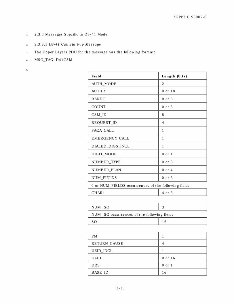
3GPP2 C.S0007-0
2-15
2.3.3 Messages Specific to DS-41 Mode 1
2.3.3.1 DS-41 Call Start-up Message 2
The Upper Layers PDU for the message has the following format: 3
MSG_TAG: D41CSM 4
5
Field Length (bits)
AUTH_MODE 2
AUTHR 0 or 18
RANDC 0 or 8
COUNT 0 or 6
CSM_ID 8
REQUEST_ID 4
PACA_CALL 1
EMERGENCY_CALL 1
DIALED_DIGS_INCL 1
DIGIT_MODE 0 or 1
NUMBER_TYPE 0 or 3
NUMBER_PLAN 0 or 4
NUM_FIELDS 0 or 8
0 or NUM_FIELDS occurrences of the following field:
CHARi 4 or 8
NUM_ SO 3
NUM_ SO occurrences of the following field:
SO 16
PM 1
RETURN_CAUSE 4
UZID_INCL 1
UZID 0 or 16
DRS 0 or 1
BASE_ID 16

3GPP2 C.S0007-0
2-16
MOB_CAPAB_INCL 1
MOB_TERM 0 or 1
MOB_P_REV 0 or 8
ENCRYPTION_SUPPORTED 0 or 4
PACA_SUPPORTED 0 or 1
NAR_AN_CAP 0 or 1
ENC_INFO_INCL 1
SIG_ENCRYPT_SUP 0 or 8
SIG_ENCRYPT_REQ 0 or 1
KEY_SEQ_NEW 0 or 4
ENC_SEC_H 0 or 24
ENC_SEQ_H_SIG 0 or 8
UI_ENCRYPT_REQ 0 or 1
UI_ENCRYPT_SUP 0 or 8
NUM_RECS 4
NUM_RECS occurrences of the following records:.
RECORD_TYPE 8
RECORD_LEN 8
<Record-type specific fields> RECORD_LEN x 8
1
AUTH_MODE – Authentication Mode. 2
This field indicates whether other authentication fields are 3
present. The mobile station shall set this field to ‘00’ if no 4
other authentication fields are present, or to ‘01’ if the 5
authentication fields below are included. All other values are 6
reserved. 7
AUTHR – Authentication Response. 8
If AUTH_MODE is ‘01’, the mobile station shall set this field to 9
the response output of the authentication algorithm. If 10
AUTH_MODE is ‘00’, the mobile station shall omit this field. 11
RANDC – Random challenge value. 12
If AUTH_MODE is ‘01’, the mobile station shall set this field to 13
the eight most significant bits of the 32-bit Random Challenge 14
held in the mobile station. If AUTH_MODE is ‘00’, the mobile 15
station shall omit this field. 16

3GPP2 C.S0007-0
2-17
COUNT – Call history parameter. 1
If AUTH_MODE is ‘01’, the mobile station shall set this field to 2
the Call History Parameter, a modulo-64 event counter 3
maintained by the mobile station and Authentication Center 4
that is used for clone detection. If AUTH_MODE is ‘00’, the 5
mobile station shall omit this field. 6
CSM_ID – Call State Machine Identifier. 7
The mobile station shall set this field to a non-zero value 8
which uniquely identifies the call/connection established by 9
this message. 10
REQUEST_ID – Request Identifier. 11
If this message is sent in response to a DS-41 Call Request 12
Message, the mobile station shall set this field to the value of 13
the REQUEST_ID field in the respective a DS-41 Call Request 14
Message; otherwise, the mobile station shall set this field to 15
‘0000’. 16
PACA_CALL – PACA Call. 17
If this call is a PACA call, the mobile station shall set this field 18
to ‘1’; otherwise, the mobile station shall set this field to ‘0’. 19
EMERGENCY_CALL – Emergency call indicator. 20
If the mobile station determines that the call is an emergency 21
call, the mobile station shall set this field to ‘1’; otherwise, the 22
mobile station shall set this field to ‘0’. 23
DIALED_DIGS_INCL – Presence indicator for the dialed digits. 24
If dialed digits are present in the message, the mobile station 25
shall set this field to ‘1’; otherwise, the mobile station shall 26
set this field to ‘0’. 27
DIGIT_MODE – Digit mode indicator. 28
This field indicates whether the dialed digits are 4-bit DTMF 29
codes or 8-bit ASCII codes using a specified numbering plan. 30
If DIALED_DIGS_INCL is set to ‘0’, the mobile station shall 31
omit this field; otherwise, the mobile station shall set this 32
field as follows: 33
To originate the call using the binary representation of DTMF 34
digits, the mobile station shall set this field to ‘0’. To originate 35
the call using ASCII characters, the mobile station shall set 36
this field to ‘1’. 37

3GPP2 C.S0007-0
2-18
NUMBER_TYPE – Type of number. 1
If DIALED_DIGS_INCL is set to ‘0’, the mobile station shall 2
omit this field; otherwise, the mobile station shall set this 3
field as follows: 4
If the DIGIT_MODE field is set to ‘1’, the mobile station shall 5
set this field to the NUMBER_TYPE value shown in Table 6
2.7.1.3.2.4-2 of [5] corresponding to the type of the number as 7
defined in Section 4.5.9 of [29]. If the DIGIT_MODE field is 8
set to ‘0’, the mobile station shall omit this field. 9
NUMBER_PLAN – Numbering plan. 10
If DIALED_DIGS_INCL is set to ‘0’, the mobile station shall 11
omit this field; otherwise, the mobile station shall set this 12
field as follows: 13
If the DIGIT_MODE field is set to ‘1’, the mobile station shall 14
set this field to the NUMBER_PLAN value shown in Table 15
2.7.1.3.2.4-3 of [5] corresponding to the requested numbering 16
plan as defined in Section 4.5.9 of [29]. If the DIGIT_MODE 17
field is set to ‘0’, the mobile station shall omit this field. 18
NUM_FIELDS – Number of dialed digits in this message. 19
If DIALED_DIGS_INCL is set to ‘0’, the mobile station shall 20
omit this field; otherwise, the mobile station shall set this 21
field as follows: 22
The mobile station shall set this field to the number of dialed 23
digits included in this message. 24
CHARi – A dialed digit or character. 25
If DIALED_DIGS_INCL is set to ‘0’, the mobile station shall 26
omit this field; otherwise, the mobile station shall set this 27
field as follows: 28
The mobile station shall include NUM_FIELDS occurrences of 29
this field. If the DIGIT_MODE field is set to ‘0’, the mobile 30
station shall set each occurrence of this field to the code value 31
shown in Table 2.7.1.3.2.4-4 of [5] corresponding to the dialed 32
digit. If the DIGIT_MODE field is set to ‘1’, the mobile station 33
shall set each occurrence of this field to the ASCII 34
representation corresponding to the dialed digit, as specified 35
in ANSI X3.4, with the most significant bit set to ‘0’. 36
NUM_ SO – Number of specified service options. 37
The mobile station shall set this field to the number of 38
supported service options included in this message. The 39
mobile station shall set this field to a value less than or equal 40
to MAX_NUM_ALT_SOs, but no less than 1. 41

3GPP2 C.S0007-0
2-19
SO – Preferred service options. 1
The mobile station shall include NUM_ SO occurrences of this 2
field, in the descending order of preference. The mobile 3
station shall set this field to the value specified in [17], 4
corresponding to the service options supported by the mobile 5
station. The mobile station shall set the first occurrence of 6
this field to the service option requested for the call. 7
PM – Privacy mode indicator. 8
To request privacy, the mobile station shall set this field to ‘1’; 9
otherwise, the mobile station shall set this field to ‘0’. 10
RETURN_CAUSE – Reason for the mobile station registration or access. 11
The mobile station shall set this field to the RETURN_CAUSE 12
value shown in Table 2.7.1.3.2.1-2 of [5] corresponding to the 13
service redirection failure condition (see 2.6.1.1 of [5]). 14
UZID_INCL – User Zone Identifier included indicator. 15
If the message is to contain the User Zone Identifier, the 16
mobile station shall set this field to ‘1’; otherwise, the mobile 17
station shall set this field to ‘0’. 18
UZID – User Zone Identifier. 19
If the UZID_INCL field is included in the message and is set to 20
‘1’, the mobile station shall include this field and set it to 21
UZIDs; otherwise, the mobile station shall omit this field. 22
DRS – Data Ready to Send. 23
If there is data to send, the mobile station shall set this field 24
to ‘1’; otherwise, the mobile station shall set this field to ‘0’. 25
BASE_ID – Identity of the base station. 26
The mobile station shall set this field to the value of the 27
BASE_ID information associated with the base station whose 28
system information was most recently read by the mobile 29
station prior to initiating the call. 30
MOB_CAPAB_INCL – Presence indicator for mobile station capability information. 31
The mobile station shall set this field to ‘1’ if information 32
about the mobile station is included in this message; 33
otherwise the mobile station shall set this field to ‘0’. 34
MOB_TERM – Mobile-terminated calls accepted indicator. 35
If MOB_CAPAB_INCL is set to ‘0’, the mobile station shall omit 36
this field; otherwise, the mobile station shall set this field as 37
follows: 38
If the mobile station is configured to accept mobile-terminated 39
calls while operating with the current roaming status (see 40
2.6.5.3 of [5]), the mobile station shall set this bit to ‘1’; 41
otherwise, the mobile station shall set this bit to ‘0’. 42

3GPP2 C.S0007-0
2-20
MOB_P_REV – Protocol revision of the mobile station. 1
If MOB_CAPAB_INCL is set to ‘0’, the mobile station shall omit 2
this field; otherwise, the mobile station shall set this field to 3
‘00000111’. 4
ENCRYPTION- – Encryption algorithms supported by the mobile station. 5
_SUPPORTED If MOB_CAPAB_INCL is set to ‘0’, the mobile station shall omit 6
this field; otherwise, the mobile station shall set this field as 7
specified in Table 2.7.1.3.2.4-5 of [5]. 8
PACA_SUPPORTED – PACA supported by the mobile station. 9
If MOB_CAPAB_INCL is set to ‘0’, the mobile station shall omit 10
this field; otherwise, the mobile station shall set this field to 11
‘1’ if the mobile station supports PACA calls, or to ‘0’ if the 12
mobile station does not support PACA calls. 13
NAR_AN_CAP – Narrow analog capability. 14
If MOB_CAPAB_INCL is set to ‘0’, the mobile station shall omit 15
this field; otherwise, the mobile station shall set this field as 16
follows: 17
If the mobile station is capable of narrow analog operation, the 18
mobile station shall set this bit to ‘1’; otherwise, the mobile 19
station shall set this bit to ‘0’. 20
ENC_INFO_INCL – Encryption fields included. 21
The mobile station shall set this field to ‘1’ if the encryption 22
related fields are included; otherwise the mobile station shall 23
set this field to ‘0’. The mobile station shall set this field to ‘1’ 24
if it is unable to determine the base station support for 25
encryption. The mobile station shall set this field to ‘0’ if the 26
base station does not support encryption or the mobile station 27
does not support any of the encryption modes supported by 28
the base station. 29
SIG_ENCRYPT_REQ – Signaling Message encryption request indicator. 30
The mobile station shall include this field if ENC_INFO_INCL 31
is equal to ‘1’. If included the mobile station shall set this 32
field to ‘1’ to request signaling encryption to be turned on. 33
SIG_ENCRYPT_SUP – Signaling Encryption supported indicator. 34
The mobile station shall include this field only if 35
ENC_INFO_INCL is equal to ‘1’. If included, this field indicates 36
which signaling encryption algorithms are supported by the 37
mobile station. 38
This field consists of the subfields shown in Table 39
2.7.1.3.2.1-5 of [5]. 40

3GPP2 C.S0007-0
2-21
KEY_SEQ_NEW – The key sequence number corresponding to the new 1
encryption key generated by the mobile station. 2
The mobile station shall include this field only if 3
ENC_INFO_INCL is equal to ‘1’ and STORE_KEYs is equal to 4
‘1’. If included, the mobile station shall set this field to 5
KEY_SEQ_NEWs-p, the sequence number associated with the 6
new encryption key generated by the mobile station. 7
ENC_SEQ_H – The 24 MSB of the EXT_ENC_SEQ 8
The mobile station shall include this field only if 9
ENC_INFO_INCL is equal to ‘1’ and the new Algorithm 1 is 10
supported by the mobile station. If this field is included, the 11
mobile station shall set this field to the 24 most significant 12
bits of the EXT_ENC_SEQ to be used as the initial value of 13
crypto sync for both forward and reverse link encryptions; 14
otherwise the mobile station shall omit this field. 15
ENC_SEQ_H_SIG – The signature of ENC_SEQ_H 16
If the ENC_SEQ_H field is included in the message, the mobile 17
station shall set this field to the digital signature of the 18
ENC_SEQ_H computed using the session encryption key; 19
otherwise, the mobile station shall omit this field. 20
UI_ENCRYPT_REQ – Request for user information encryption on the traffic channel 21
indicator. 22
The mobile station shall include this field only if 23
ENC_INFO_INCL is equal to ‘1’. If this field is included, the 24
mobile station shall set this field to ‘1’ to request user 25
information encryption. Otherwise, the mobile station shall 26
set this field to ‘0’. 27
UI_ENCRYPT_SUP – User information encryption supported indicator. 28
The mobile station shall include this field only if 29
ENC_INFO_INCL is equal to ‘1’. If this field is included, the 30
mobile station shall set this field to indicate the supported 31
user information encryption algorithms. 32
This field consists of the subfields shown in Table 33
2.7.1.3.2.4-7 of [5]. 34
The mobile station shall set each subfield to ‘1’ if the 35
corresponding user information encryption algorithm is 36
supported by the mobile station; otherwise, the mobile station 37
shall set the subfield to ‘0’. 38
NUM_ RECS – Number of information records included in this message. 39
The mobile station shall set this field to the number of 40
information records included in this message. 41
RECORD_TYPE – Type of the information record. 42
The mobile station shall set this field to the type of the 43
included record (see 2.7.4 of [5]). 44

3GPP2 C.S0007-0
2-22
RECORD_LEN – Length of the information record. 1
The mobile station shall set this field to the length in bytes of 2
the included record (see 2.7.4 of [5]). 3
<Record-type specific fields> – Fields specific to the information record. 4
The mobile station shall set these fields to values specific for 5
the type of the included record (see 2.7.4 of [5]). 6

3GPP2 C.S0007-0
2-23
2.3.3.2 DS-41 Registration Message 1
The Upper Layers PDU for the message has the following format: 2
MSG_TAG: D41RGM 3
4
Field Length (bits)
AUTH_MODE 2
AUTHR 0 or 18
RANDC 0 or 8
COUNT 0 or 6
REG_TYPE 4
MOB_P_REV 8
MOB_TERM 1
RETURN_CAUSE 4
BASE_ID 16
UZID_INCL 1
UZID 0 or 16
ENC_INFO_INCL 1
SIG_ENCRYPT_SUP 0 or 8
SIG_ENCRYPT_REQ 0 or 1
KEY_SEQ_NEW 0 or 4
ENC_SEQ_H 0 or 24
ENC_SEQ_H_SIG 0 or 8
UI_ENCRYPT_SUP 0 or 8
5
AUTH_MODE – Authentication Mode. 6
This field indicates whether other authentication fields are 7
present. The mobile station shall set this field to ‘00’ if no 8
other authentication fields are present, or to ‘01’ if the 9
authentication fields below are included. All other values are 10
reserved. 11
AUTHR – Authentication Response. 12
If AUTH_MODE is ‘01’, the mobile station shall set this field to 13
the response output of the authentication algorithm. If 14
AUTH_MODE is ‘00’, the mobile station shall omit this field. 15

3GPP2 C.S0007-0
2-24
RANDC – Random challenge value. 1
If AUTH_MODE is ‘01’, the mobile station shall set this field to 2
the eight most significant bits of the 32-bit Random Challenge 3
held in the mobile station. If AUTH_MODE is ‘00’, the mobile 4
station shall omit this field. 5
COUNT – Call history parameter. 6
If AUTH_MODE is ‘01’, the mobile station shall set this field to 7
the Call History Parameter, a modulo-64 event counter 8
maintained by the mobile station and Authentication Center 9
that is used for clone detection. If AUTH_MODE is ‘00’, the 10
mobile station shall omit this field. 11
REG_TYPE – Registration type. 12
This field indicates which type of event generated the 13
registration attempt. 14
The mobile station shall set this field to the REG_TYPE value 15
shown in Table 2.7.1.3.2.1-1 of [5] corresponding to the event 16
that caused this registration to occur (see 2.6.5.1 of [5]), 17
except for the value ‘0110’ which is reserved. 18
MOB_P_REV – Protocol revision of the mobile station. 19
The mobile station shall set this field to ‘00000111’. 20
MOB_TERM – Mobile terminated calls accepted indicator. 21
If the mobile station is configured to accept mobile-terminated 22
calls while operating with the current roaming status (see 23
2.6.5.3 of [5]), the mobile station shall set this bit to ‘1’; 24
otherwise, the mobile station shall set this bit to ‘0’. 25
RETURN_CAUSE – Reason for the mobile station registration or access. 26
The mobile station shall set this field to the RETURN_CAUSE 27
value shown in Table 2.7.1.3.2.1-2 of [5] corresponding to the 28
service redirection failure condition (see 2.6.1.1 of [5]). 29
BASE_ID – Identity of the base station. 30
The mobile station shall set this field to the value of the 31
BASE_ID information associated with the base station whose 32
system information was most recently read by the mobile 33
station prior to initiating the call. 34
UZID_INCL – User Zone Identifier included indicator. 35
If the message is to contain the User Zone Identifier, the 36
mobile station shall set this field to ‘1’; otherwise, the mobile 37
station shall set this field to ‘0’. 38
UZID – User Zone Identifier. 39
If the UZID_INCL field is included in the message and is set to 40
‘1’, the mobile station shall include this field and set it to 41
UZIDs; otherwise, the mobile station shall omit this field. 42

3GPP2 C.S0007-0
2-25
ENC_INFO_INCL – Encryption fields included. 1
The mobile station shall set this field to ‘1’ if the encryption 2
related fields are included; otherwise the mobile station shall 3
set this field to ‘0’. The mobile station shall set this field to ‘1’ 4
if it is unable to determine the base station support for 5
encryption. The mobile station shall set this field to ‘0’ if the 6
base station does not support encryption or the mobile station 7
does not support any of the encryption modes supported by 8
the base station. 9
SIG_ENCRYPT_SUP – Signaling Encryption supported indicator. 10
The mobile station shall include this field only if 11
ENC_INFO_INCL is equal to ‘1’. If included, this field indicates 12
which signaling encryption algorithms are supported by the 13
mobile station. 14
This field consists of the subfields shown in Table 15
2.7.1.3.2.1-5 of [5]. 16
The mobile station shall set the CMEA subfield to ‘1’. 17
The mobile station shall set each remaining subfield to ‘1’ if 18
the corresponding signaling algorithm is supported by the 19
mobile station; otherwise, the mobile station shall set the 20
subfield to ‘0’. 21
SIG_ENCRYPT_REQ – Signaling Message encryption request indicator. 22
The mobile station shall include this field if ENC_INFO_INCL 23
is equal to ‘1’. If included the mobile station shall set this 24
field to ‘1’ to request signaling encryption to be turned on for 25
signaling messages sent on the f-dsch, r-dsch, f-csch, or 26
r-csch. 27
KEY_SEQ_NEW – Key sequence number corresponding to the new encryption key 28
generated by the mobile station. 29
The mobile station shall include this field only if ENC_INFO_INCL 30
is equal to ‘1’ and if STORE_KEYs is equal to ‘1’. If included, the 31
mobile station shall set this field to KEY_SEQ_NEWs-p, which is 32
the sequence number associated with the new encryption key 33
generated by the mobile station. 34
ENC_SEQ_H – The 24 MSB of the EXT_ENC_SEQ. 35
The mobile station shall include this field only if ENC_INFO_INCL 36
is equal to ‘1’ and if the new Algorithm 1 is supported by the 37
mobile station. If included, the mobile station shall set this field 38
to the 24 most significant bits of the EXT_ENC_SEQ to be used as 39
the initial value of crypto-sync for both forward and reverse link 40
encryptions; otherwise the mobile station shall omit this field. 41
ENC_SEQ_H_SIG – The signature of ENC_SEQ_H. 42
If the ENC_SEQ_H field is included in the message, the mobile 43
station shall set this field to the digital signature of the 44
ENC_SEQ_H computed using the session encryption key; 45
otherwise, the mobile station shall omit this field. 46

3GPP2 C.S0007-0
2-26
UI_ENCRYPT_SUP – User information encryption supported indicator. 1
The mobile station shall include this field only if 2
ENC_INFO_INCL is equal to ‘1’. If this field is included, the 3
mobile station shall set this field to indicate the supported 4
user information encryption algorithms. 5
This field consists of the subfields shown in Table 6
2.7.1.3.2.4-7 of [5]. 7
The mobile station shall set each subfield to ‘1’ if the 8
corresponding user information encryption algorithm is 9
supported by the mobile station; otherwise, the mobile station 10
shall set the subfield to ‘0’. 11
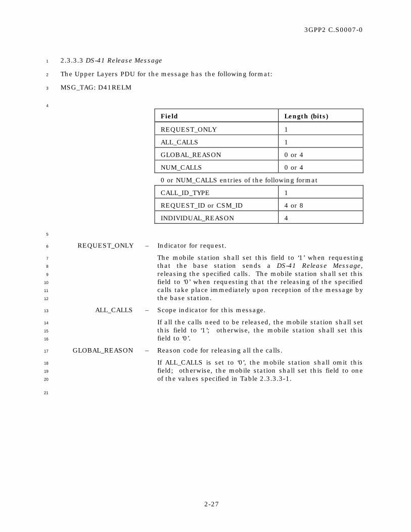
3GPP2 C.S0007-0
2-27
2.3.3.3 DS-41 Release Message 1
The Upper Layers PDU for the message has the following format: 2
MSG_TAG: D41RELM 3
4
Field Length (bits)
REQUEST_ONLY 1
ALL_CALLS 1
GLOBAL_REASON 0 or 4
NUM_CALLS 0 or 4
0 or NUM_CALLS entries of the following format
CALL_ID_TYPE 1
REQUEST_ID or CSM_ID 4 or 8
INDIVIDUAL_REASON 4
5
REQUEST_ONLY – Indicator for request. 6
The mobile station shall set this field to ‘1’ when requesting 7
that the base station sends a DS-41 Release Message, 8
releasing the specified calls. The mobile station shall set this 9
field to ‘0’ when requesting that the releasing of the specified 10
calls take place immediately upon reception of the message by 11
the base station. 12
ALL_CALLS – Scope indicator for this message. 13
If all the calls need to be released, the mobile station shall set 14
this field to ‘1’; otherwise, the mobile station shall set this 15
field to ‘0’. 16
GLOBAL_REASON – Reason code for releasing all the calls. 17
If ALL_CALLS is set to ‘0’, the mobile station shall omit this 18
field; otherwise, the mobile station shall set this field to one 19
of the values specified in Table 2.3.3.3-1. 20
21

3GPP2 C.S0007-0
2-28
Table 2.3.3.3-1. Release “Reason” Codes 1
GLOBAL_REASON or
INDIVIDUAL_REASON
Description
‘0000’ Unspecified
‘0001’ User requested
‘0010’ Could not meet QoS
‘0011’ Preemption by emergency or higher priority call
‘0100’ Too many simultaneous calls
‘0101’ SO incompatibility
‘0110’ Out of physical resources
‘0111’ Out of monetary resources
‘1000’ SIM card removed
‘1001’ Service Denied
‘1010’ Power Down
‘1011’-‘1111’ Reserved
2
NUM_CALLS – Number of calls to be released by this message. 3
If ALL_CALLS is set to ‘1’, the mobile station shall omit this 4
field; otherwise, the mobile station shall set this field to the 5
number of calls to be released by this message. 6
CALL_ID_TYPE – Type of the call identifier. 7
The mobile station shall set this field to ‘0’ if the call is 8
identified by a CSM_ID. The mobile station shall set this field 9
to ‘1’ if the call is identified by a REQUEST_ID. 10
REQUEST_ID or CSM_ID – Call identifier. 11
If CALL_ID_TYPE is set to ‘0’, the mobile station shall set this 12
field to the CSM_ID of the call to be released; otherwise, the 13
mobile station shall set this field to the REQUEST_ID of the 14
call to be released. 15
INDIVIDUAL_REASON – Reason code for releasing the specific call. 16
The mobile station shall set this field to one of the values 17
specified in Table 2.3.3.3-1. 18

3GPP2 C.S0007-0
2-29
2.3.3.4 DS-41 Service Option Connect Complete Message 1
The Upper Layers PDU for the message has the following format: 2
MSG_TAG: D41SOCCM 3
4
Field Length (bits)
CON_REF 0 or 8
5
CON_REF – Connection Reference. 6
If the message is sent in response to a DS-41 Service Option 7
Connect Message or a DS-41 Service Option Disconnect 8
Message which affect only one call or connection, the mobile 9
station shall include this field and shall set it to the CSM_ID 10
value for the call or connection; otherwise, the mobile station 11
shall omit this field. 12

3GPP2 C.S0007-0
2-30
2.3.4 PDU Format 1
When transmitting an Upper Layers message, the mobile station shall use the following 2
Upper Layers PDU format for the “NAS Message” information element in the INITIAL 3
DIRECT TRANSFER message and the UPLINK DIRECT TRANSFER message: 4
5
Field Length (bits)
MSG_PID 2
MSG_ID 6
ENC_FIELDS_INCL 1
SIG_ENCRYPT_MODE 0 or 3
ENC_SEQ 0 or 8
Upper Layers SDU variable
6
MSG_PID – Message Protocol Identifier. 7
The mobile station shall set the field to ‘00’ 8
MSG_ID – Message Identifier. 9
The mobile station shall set the field as specified in Table 10
2.3.4-1. 11
ENC_FIELDS_INCL – Encryption fields included indicator. 12
The mobile station shall set the ENC_FIELDS_INCL field to ‘1’ 13
if Upper Layers enhanced encryption fields are included in 14
this message; otherwise, the mobile station shall set the 15
ENC_FIELDS_INCL field to ‘0’. The mobile station shall set 16
this field to ‘0’ whenever the MSG_ID corresponds to a DS-41 17
Registration Message. 18
SIG_ENCRYPT_MODE – Signaling Encryption mode in use. 19
If ENC_FIELDS_INCL is set to ‘0’, the mobile station shall omit 20
the SIG_ENCRYPT_MODE field; otherwise the mobile station 21
shall set the SIG_ENCRYPT_MODE field to the 22
SIG_ENCRYPT_MODE (see Table 2.7.1.3.2.1-5 of [5]) used for 23
SDU carried by this PDU. 24
ENC_SEQ – The eight least significant bits of the Encryption sequence 25
number used to construct a cryptographic synchronization 26
crypto-sync (see 2.3.12.4 of [5]) for the encryption algorithm. 27
If the SIG_ENCRYPT_MODE field is not included or is set to a 28
value other than ‘01000000’ (see Table 2.7.1.3.2.1-5 of [5]), 29
the mobile station shall omit the ENC_SEQ field; otherwise, 30
the mobile station shall set the ENC_SEQ field to the eight 31
least significant bits of the 32 bit crypto-sync (see 2.3.12.4 of 32
[5]). 33
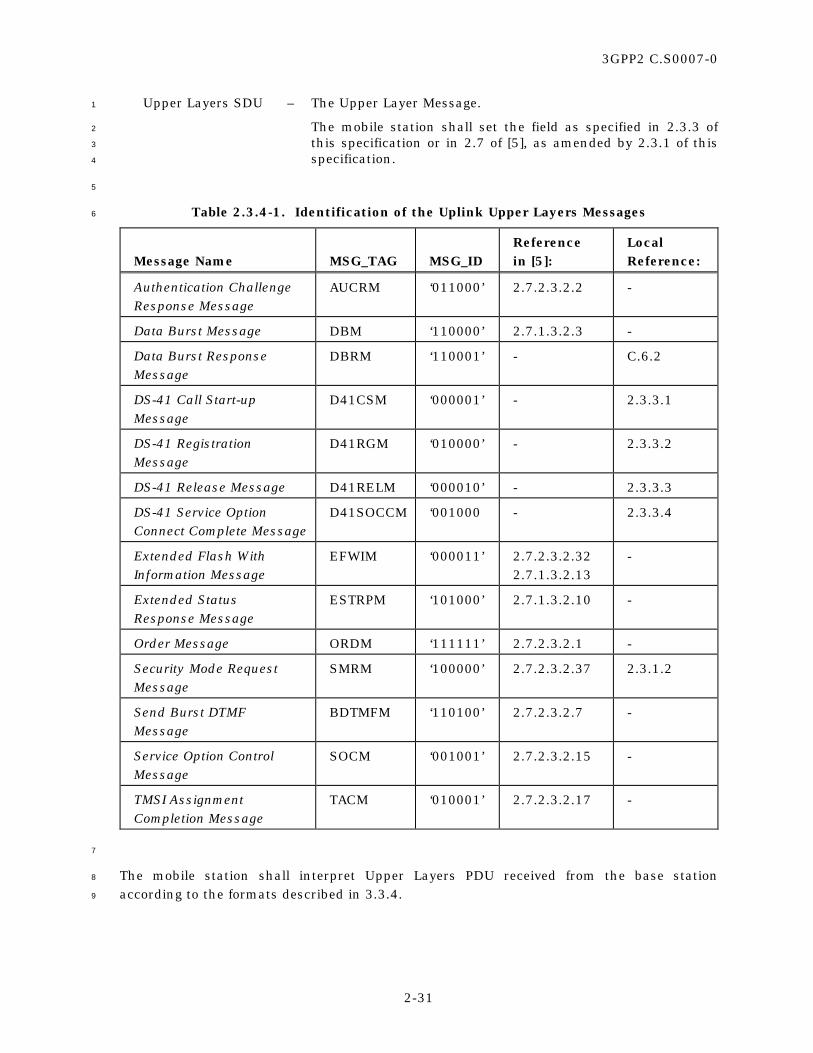
3GPP2 C.S0007-0
2-31
Upper Layers SDU – The Upper Layer Message. 1
The mobile station shall set the field as specified in 2.3.3 of 2
this specification or in 2.7 of [5], as amended by 2.3.1 of this 3
specification. 4
5
Table 2.3.4-1. Identification of the Uplink Upper Layers Messages 6
Message Name
MSG_TAG
MSG_ID
Reference in [5]:
Local Reference:
Authentication Challenge Response Message
AUCRM ‘011000’ 2.7.2.3.2.2 -
Data Burst Message DBM ‘110000’ 2.7.1.3.2.3 -
Data Burst Response Message
DBRM ‘110001’ - C.6.2
DS-41 Call Start-up Message
D41CSM ‘000001’ - 2.3.3.1
DS-41 Registration Message
D41RGM ‘010000’ - 2.3.3.2
DS-41 Release Message D41RELM ‘000010’ - 2.3.3.3
DS-41 Service Option Connect Complete Message
D41SOCCM ‘001000 - 2.3.3.4
Extended Flash With Information Message
EFWIM ‘000011’ 2.7.2.3.2.32 2.7.1.3.2.13
-
Extended Status Response Message
ESTRPM ‘101000’ 2.7.1.3.2.10 -
Order Message ORDM ‘111111’ 2.7.2.3.2.1 -
Security Mode Request Message
SMRM ‘100000’ 2.7.2.3.2.37 2.3.1.2
Send Burst DTMF Message
BDTMFM ‘110100’ 2.7.2.3.2.7 -
Service Option Control Message
SOCM ‘001001’ 2.7.2.3.2.15 -
TMSI Assignment Completion Message
TACM ‘010001’ 2.7.2.3.2.17 -
7
The mobile station shall interpret Upper Layers PDU received from the base station 8
according to the formats described in 3.3.4. 9

3GPP2 C.S0007-0
2-32
2.3.5 Timers and Constants 1
The mobile station shall meet the timing constraints reflected in the values for the timers, 2
as specified in Section 13 of [14]. The mobile station shall meet the timing constraints 3
reflected in the values for the T56m, T57m, T64m, T66m, T69m, as described in Annex D of 4
[5]. The mobile station shall meet the timing constraint indicated by the T33m timer when 5
executing ordered registration (see 2.2.4). 6

3GPP2 C.S0007-0
3-1
3 REQUIREMENTS FOR DS-41 BASE STATIONS 1
3.1 Signaling Between the Base Station and the Mobile Station 2
When no RRC connection between the base station and the mobile station exists, the base 3
station shall proceed as described in [11]. 4
In the absence of an RRC connection to a mobile station, and when solicited by that mobile 5
station, the base station should establish (or re-establish, in case of an RF failure) an RRC 6
connection to the mobile station (see 8.1.3 of [14]). The base station shall inform the mobile 7
station if it cannot establish an RRC connection. The base station should obtain the 8
capabilities information of the mobile station (see [14]) as early as practical, while or after 9
the RRC connection is established. 10
For the duration of the RRC connection, the base station shall establish a bi-directional 11
(uplink and downlink) logical dedicated channel capable of transporting the INITIAL 12
DIRECT TRANSFER message, the UPLINK DIRECT TRANSFER message and the 13
DOWNLINK DIRECT TRANSFER messages (see 8.1.8 of [14]) in acknowledged mode (see 14
4.2.1.3 of [12]). The base station may also establish a link for unacknowledged transfers 15
(see 4.2.1.2 of [12]). The base station may release the RRC connection to a mobile station 16
at any time. 17
While an RRC connection to a mobile station exists, the base station may perform RRC-18
related operations in connected mode with respect to the mobile station, as described in 19
[10] and [14]. 20
3.1.1 Sending Upper Layers-related Information to the Mobile Station 21
The base station shall broadcast system information on the logical broadcast channel 22
BCCH (see 8.1.1 of [14]). The base station may send broadcast SMS messages on the CTCH 23
logical channel. 24
In the absence of an RRC connection, the base station should page the mobile station on 25
the logical paging channel PCCH (see 8.1.2 of [14]), should wait for the mobile station to 26
solicit an RRC connection, and then establish the RRC connection and the associated 27
logical dedicated channel. 28
If an RRC connection exists, but is in a state that does not allow immediate communication 29
with the mobile station on the logical dedicated control channel (see 9.3.3 and 9.3.4 of [14]), 30
the base station should page the mobile station on the logical paging channel PCCH, wait 31
for the mobile station to respond, and then activate the logical dedicated channel. 32

3GPP2 C.S0007-0
3-2
When the logical dedicated channel is available for communication, the base station may 1
send Upper Layers-related messages to the mobile station. In such cases, the base station 2
shall generate a DOWNLINK DIRECT TRANSFER message, shall set the “CN Domain 3
Identifier” information element as described in 8.1.9.2 of [14], shall set the “NAS Message” 4
information element to contain the Upper Layers message, and shall transmit the 5
DOWNLINK DIRECT TRANSFER message on the downlink dedicated logical channel. If the 6
Upper Layer message must be sent in assured mode, the base station shall send the 7
DOWNLINK DIRECT TRANSFER message in acknowledged mode (see 4.2.1.3 of [12]); 8
otherwise, the base station may send the DOWNLINK DIRECT TRANSFER message in 9
unacknowledged mode (see 4.2.1.2 of [12]). 10
For each active logical connection, the base station shall not send more than four Upper 11
Layer messages requiring acknowledgement before receiving acknowledgment of the 12
reception of at least one of the messages. For services having inactive logical connections 13
or no logical connections, the base station shall not send more than four Upper Layer 14
messages requiring acknowledgment before receiving acknowledgment of the reception of at 15
least one of the messages. 16
3.1.2 Receiving Upper Layers-related Information from the Mobile Station 17
The base station receives Upper Layers-related information only if a logical dedicated 18
channel exists between the base station and the mobile station.12 If such a connection 19
does not exist, the base station establishes one upon reception (on the logical common 20
control channel CCCH) of a request from the mobile station. 21
Upon reception on the dedicated logical channel of an INITIAL DIRECT TRANSFER message 22
or an UPLINK DIRECT TRANSFER message from the mobile station, the base station shall 23
extract the Upper Layers message from the “NAS Message” information element and process 24
it. 25
Messages that can be identified and decrypted correctly, but that are found to be longer 26
than expected, should be processed up to the expected length (extraneous information 27
should be ignored). Messages that cannot be identified, that cannot be decrypted correctly, 28
or that are shorter than expected, should be rejected (by informing the mobile station of the 29
error) or ignored. 30
3.2 Procedures 31
When requirements are specified based upon sections in [5], the following rules shall apply 32
with regard to that text: 33
• Specific sections in [5] referenced in this text shall be understood as including all of 34
their subsections, unless indicated otherwise. 35
• References to messages, orders, information records, or information elements that 36
are not supported shall be ignored. 37
12 Except for system information broadcast and broadcast SMS.

3GPP2 C.S0007-0
3-3
• Redirections and transitions to unsupported states should be understood as 1
redirections to equivalent states or to states that can properly handle the triggering 2
condition. 3
• Requirements pertaining to RRC behaviors, procedures or variables shall be ignored. 4
• Amendments and new requirements specified by this specification shall take 5
precedence over any corresponding text in [5]. 6
If the base station receives a Mobile Station Reject Order during a multi-message procedure, 7
the base station should abandon the procedure, unless there is enough information to allow 8
recovery and continuation of the procedure. 9
3.2.1 System Broadcast 10
The base station shall broadcast general and RRC-related information according to the 11
requirements in [14]. The base station shall broadcast Upper Layers-related system 12
information in the Master Information Block and the System Information Block type 13, as 13
specified in Table 3.3.4-2. The base station may broadcast Upper Layers-related system 14
information in the sub-blocks of the System Information Block type 13, as specified in Table 15
3.3.4-2. 16
3.2.2 Call Processing 17
Call Control signaling from the base station to the mobile station shall take place on 18
dedicated logical control channels. The messages shall be sent in assured mode. 19
The base station should treat concurrent calls independently from the perspective of Upper 20
Layers signaling, except in the case where common action on more than one call is specified 21
(e.g., call release). 22
3.2.2.1 Call Setup for Mobile Station-originated Calls 23
The origination procedure is used to perform circuit and packet call originations as well as 24
packet registrations. 25
The origination procedure starts when the base station receives the DS-41 Call Start-Up 26
Message on the dedicated control channel: 27
• If the DS-41 Call Start-Up Message requests the establishment of a call, the base 28
station should select the best available service option from the list presented by the 29
mobile station, should set up the proper radio bearers capable to support the traffic, 30
based upon default or explicit QoS information, should assign a non-zero value for 31
the “RAB ID” field of the DS-41 Service Configuration Record, should send a DS-41 32
Service Option Connect Message, and should proceed with the call. If the call cannot 33
be processed successfully, the base station should send a DS-41 Release Message. 34
• If the DS-41 Call Start-Up Message requests only a packet registration and the 35
packet registration is successful, the base station should assign a value of zero for 36
the “RAB ID” field of the DS-41 Service Configuration Record and should send the 37
record as part of the DS-41 Service Option Connect Message. 38

3GPP2 C.S0007-0
3-4
• If the DS-41 Call Start-Up Message requests only a packet registration and the 1
packet registration is not successful, the base station should send a DS-41 Service 2
Option Disconnect Message or should send a DS-41 Release Message. 3
The base station may abandon the origination procedure at any time (see 3.2.2.4). 4
The base station may send a Reorder Order to the mobile station, to cause the restart of the 5
origination procedure. 6
During the origination procedure, the base station may start (and may complete) other 7
origination procedures and mobile termination procedures, using a different CSM_ID. 8
3.2.2.2 Call Setup for Mobile Station-terminated Calls 9
To initiate the mobile station-terminated procedure, the base station shall send a DS-41 10
Call Request Message with a service option and QoS parameters deemed acceptable to the 11
mobile station.13 12
If a DS-41 Call Start-Up Message tagged with the REQUEST_ID value used in the DS-41 Call 13
Request Message is received, the base station should set up the proper radio bearers 14
capable to support the traffic, based upon the default or explicit QoS information, should 15
assign a non-zero value for the “RAB ID” field of the Service Configuration Record, and 16
should send a DS-41 Service Option Connect Message. 17
Upon confirmation of the successful delivery of the DS-41 Service Option Connect Message: 18
If the BYPASS_ALERT_ANSWER field in the DS-41 Call Request Message was set to ‘1’, the 19
base station should proceed with the call. 20
Otherwise, the base station should send the Extended Alert With Information Message to 21
alert the user of the incoming call; and if the base station subsequently receives a Connect 22
Order, indicating that the user has answered the call, the base station should proceed with 23
the call. Alternatively, if an Extended Flash With Information Message carrying call 24
forwarding information is received in lieu of the Connect Order, the base station should end 25
the termination procedure and the call. If the received Extended Flash With Information 26
Message carries Answer Hold information (see 2.7.4 of [5]), the base station shall suspend 27
or shall resume the call, as appropriate. 28
The base station may abandon the termination procedure at any time (see 3.2.2.4) 29
During the termination procedure, the base station may start (and may complete) other 30
origination procedures and mobile termination procedures, using a different CSM_ID and 31
REQUEST_ID. 32
3.2.2.3 Signaling During a Call 33
The base station should process a received Extended Flash With Information Message 34
according to the requirements in [5] for the information records carried by the message. 35
13 Such information can normally become available during registration.

3GPP2 C.S0007-0
3-5
At any time during the call, the base station may send an Extended Flash With Information 1
Message to the mobile station. 2
To alert the user, the base station may send the Extended Alert With Information Message 3
carrying information records specified in 3.7.5 of [5]. During a PACA origination procedure 4
the base station may send the PACA Message to indicate the position of the call in the PACA 5
queue, or to indicate the call cancel or call restart commands. 6
3.2.2.4 Call Clearing 7
If the base station receives a DS-41 Release Message soliciting the release of the call, the 8
base station shall send a DS-41 Release Message. The base station may reply to a DS-41 9
Release Message with a DS-41 Release Message affecting the same connection as the one 10
specified in the received message. If a received DS-41 Release Message attempts to clear a 11
connection that does not exist, the base station should ignore the received message. 12
Upon reception of a DS-41 Release Message releasing the call, in case of irrecoverable RRC 13
failure, or in case of expiration of procedure-related timers the base station should abandon 14
the origination or termination procedures, if in progress, and it should clear the call. 15
The base station may release or disconnect calls at any time by sending the DS-41 Release 16
Message, a DS-41 Service Option Connect Message which performs releases, or the DS-41 17
Service Option Disconnect Message. 18
When sending a DS-41 Release Message, the base station may provide advice-of-charge and 19
other end-of-call-related information. 20
After releasing a last call, the base station may disconnect the signaling RRC connection 21
(see 8.1.4 of [14]). 22
3.2.3 Mobility Management Services Processing 23
The base station shall meet the requirements in 3.6.5 of [5], as amended by this section. 24
The base station shall use only the logical dedicated channel DCCH when it performs 25
mobility management signaling (i.e., for registration and TMSI assignment). 26
Requirements placed on the processing of the Origination Message and Page Response 27
Message with respect to registration shall be interpreted as requirements placed on the 28
processing of the DS-41 Call Start-Up Message. Requirements placed on the processing of 29
the Registration Message shall be interpreted as requirements placed on the processing of 30
the DS-41 Registration Message. 31
Requirements related to the SLOT_CYCLE_INDEX and the MC-41 Station Class Mark do 32
not apply. 33
The authentication and ciphering requirements in 3.3.1 and 3.3.2 of [5] shall apply. 34
Requirements in 2.3.12 of [5] shall also apply, as amended by 2.2.4 of this specification. 35
3.2.4 Broadcast SMS 36
The base station may send broadcast SMS messages according to [13]. If the base station 37
sends a broadcast Data Burst Message, the base station shall encapsulate the message as 38

3GPP2 C.S0007-0
3-6
the “CB Data” information element of the BMC CBS message. The base station should send 1
the BMC CBS message on the FACH at the advertised time (see 10.1 of [13]). Information 2
on further broadcast SMS activity is communicated by the base station via the BMC 3
SCHEDULE message transmitted on the FACH, together with the BMC CBS message (see 4
10.2 of [13]). 5
3.3 Messages Sent by the Base Station 6
When communicating with the mobile station, the base station shall be able to send all the 7
mandatory supported messages and orders specified in 3.7 of [5], with the exception of the 8
following messages and orders which shall not be sent: 9
• Access Parameters Message 10
• Alert With Information Message 11
• Analog Handoff Direction Message 12
• Call Assignment Message 13
• Candidate Frequency Search Control Message 14
• Candidate Frequency Search Request Message 15
• CDMA Channel List Message 16
• Channel Assignment Message 17
• Enhanced Access Parameters Message 18
• Extended CDMA Channel List Message 19
• Extended Channel Assignment Message 20
• Extended Handoff Direction Message 21
• Extended Neighbor List Message 22
• Extended Neighbor List Update Message 23
• Extended Release Message 24
• Extended Release Mini Message 25
• Extended Supplemental Channel Assignment Message 26
• Extended System Parameters Message 27
• Flash With Information Message 28
• Forward Supplemental Channel Assignment Mini Message 29
• General Handoff Direction Message 30
• General Neighbor List Message 31
• General Page Message 32
• Global Service Redirection Message 33
• In-traffic System Parameters Message 34

3GPP2 C.S0007-0
3-7
• Long Code Transition Request Order 1
• MC-RR Parameters Message 2
• Mobile Assisted Burst Operation Parameters Message 3
• Neighbor List Message 4
• Neighbor List Update Message 5
• Outer Loop Report Order 6
• Pilot Measurement Request Order 7
• Periodic Pilot Measurement Request Order 8
• Power Control Message 9
• Power Control Parameters Message 10
• Power Up Function Message 11
• Power Up Function Control Message 12
• Release Order 13
• Resource Allocation Message 14
• Resource Allocation Mini Message 15
• Retrieve Parameters Message 16
• Reverse Supplemental Channel Assignment Mini Message 17
• Service Connect Message 18
• Service Option Request Order 19
• Service Option Response Order 20
• Service Request Message 21
• Service Response Message 22
• Set Parameters Message 23
• Slotted Mode Order 24
• Status Request Message 25
• Status Request Order 26
• Supplemental Channel Assignment Message 27
• Sync Channel Message (the P_REV, MIN_P_REV, SID and NID fields are used in the 28
Master Information Block; see 3.3.1.1) 29
• System Parameters Message 30
• Universal Handoff Direction Message 31
For the messages in use, the base station shall use the PDU formats specified in 3.7.2.3 32
and 3.7.3.3 of [5], as amended by 3.3.1 of this specification. 33

3GPP2 C.S0007-0
3-8
For the information records, the base station shall use the formats specified in 2.7.5 of [5], 1
as amended by 3.2.2 of this specification. 2
The base station should be able to send the DS-41 specific messages specified in Section 3
3.3.3. 4
3.3.1 Modifications to Layer 3 PDUs Described in [5] 5
3.3.1.1 Sync Channel Message 6
The following fields of the Sync Channel Message: P_REV, MIN_P_REV, SID, and NID, are 7
used in a DS-41 system. These values are carried in the MIB. The base station shall set 8
these fields as specified in 3.7.2.3.2.26 of [5]. 9
3.3.1.2 ANSI-41 Systems Parameter Message 10
The base station shall omit the PILOT_PN and CONFIG_MSG_SEQ fields. The base station 11
shall set DIST_REG_INCL to ‘0’ and OTHER_INFO_INCL to ‘1’ . The base station shall set 12
the included fields as specified in 3.7.2.3.2.29 of [5]. 13
3.3.1.3 ANSI-41 RAND Message 14
The base station shall omit the PILOT_PN field. The base station shall set the included 15
fields as specified in 3.7.2.3.2.31 of [5]. 16
3.3.1.4 User Zone Identification Message 17
The base station shall omit the PILOT_PN and CONFIG_MSG_SEQ fields. 18
The base station shall set the UZID_EXIT field to a value corresponding to a threshold for 19
the quality of the received signal ([11] defines the quality of the received signal for cell 20
reselection). The same definition applies to the quality of received signal for UZID_EXIT). 21
The base station shall set the other included fields as specified in 3.7.2.3.2.23 of [5]. 22
3.3.1.5 Private Neighbor List Message 23
The base station shall omit the PILOT_PN field. The base station shall set the fields as 24
specified in 3.7.2.3.2.24 of [5]. 25
3.3.1.6 Extended Global Service Redirection Message 26
The base station shall omit the PILOT_PN and CONFIG_MSG_SEQ fields. The base station 27
shall set the fields as specified in 3.7.2.3.2.27 of [5]. 28
3.3.1.7 Status Request Message 29
In addition to the requirements in 3.7.3.3.2.16 of [5], the base station may set the 30
OP_MODE field to ‘00000101’ for the DS-41 operating mode (see C.5.2). 31

3GPP2 C.S0007-0
3-9
3.3.1.8 Security Mode Command Message 1
The base station shall use the format specified in 3.7.3.3.2.44 of [5], except that the 2
ACTION_TIME field shall be replaced by the 8-bit ACTIVATION_TIME. If included, the field 3
shall be set as specified in 10.2.3.1 of [14]. The base station shall set the NUM_RECS field 4
to ‘000’. All other fields shall be set as specified in 3.7.3.3.2.44 of [5]. 5
3.3.1.9 Order Message 6
The base station shall use the format specified in 3.7.3.3.2.1 of [5], except that the 7
ACTION_TIME field shall be replaced by the 8-bit ACTIVATION_TIME. If included, the field 8
shall be set as specified in 10.2.3.1 of [14]. The base station shall set the ORDER field to 9
values corresponding to orders supported by the mobile station (see 3.3). All other fields 10
shall be set as specified in 3.7.3.3.2.1 of [5]. 11
3.3.1.10 Mobile Station Registered Message 12
The base station shall omit the BASE_LAT, BASE_LONG and REG_DIST fields. 13
3.3.2 DS-41 Modifications to Information Records Described in [5] 14
When communicating with a dual-mode DS-41/MC-41 mobile station, the base station 15
shall be able to include in signaling messages all the mandatory supported information 16
records specified in 3.7.5 of [5]. 17
When communicating with a DS-41 mobile station that does not support the MC-41 18
operating mode, the base station shall be able to include in signaling messages all the 19
mandatory supported information records specified in 3.7.5 of [5] with the exception of the 20
Service Configuration Information record, which does not have to be supported. 21
Instead, the base station shall support the following service configuration information 22
record and shall be able to include it in a DS-41 Service Option Connect Message to specify a 23
service configuration to be used: 24
25
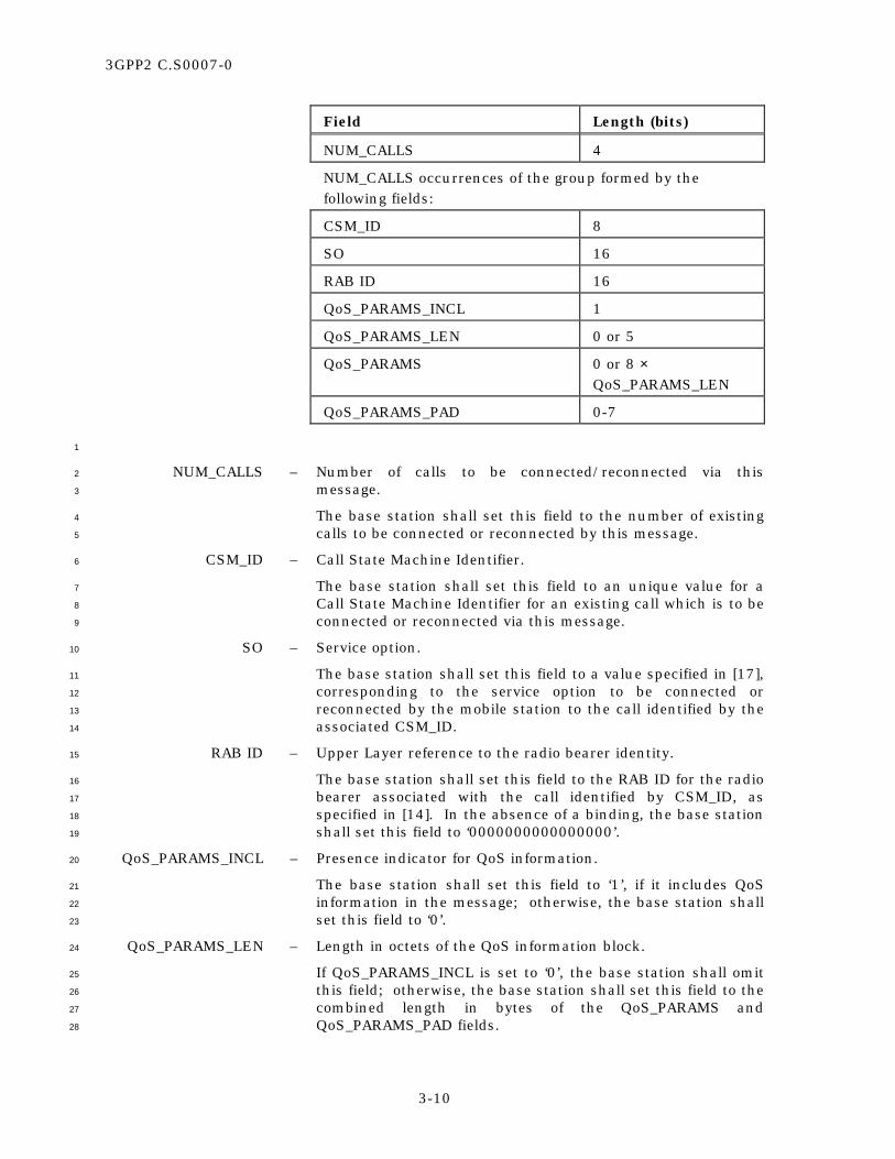
3GPP2 C.S0007-0
3-10
Field Length (bits)
NUM_CALLS 4
NUM_CALLS occurrences of the group formed by the following fields:
CSM_ID 8
SO 16
RAB ID 16
QoS_PARAMS_INCL 1
QoS_PARAMS_LEN 0 or 5
QoS_PARAMS 0 or 8 × QoS_PARAMS_LEN
QoS_PARAMS_PAD 0-7
1
NUM_CALLS – Number of calls to be connected/reconnected via this 2
message. 3
The base station shall set this field to the number of existing 4
calls to be connected or reconnected by this message. 5
CSM_ID – Call State Machine Identifier. 6
The base station shall set this field to an unique value for a 7
Call State Machine Identifier for an existing call which is to be 8
connected or reconnected via this message. 9
SO – Service option. 10
The base station shall set this field to a value specified in [17], 11
corresponding to the service option to be connected or 12
reconnected by the mobile station to the call identified by the 13
associated CSM_ID. 14
RAB ID – Upper Layer reference to the radio bearer identity. 15
The base station shall set this field to the RAB ID for the radio 16
bearer associated with the call identified by CSM_ID, as 17
specified in [14]. In the absence of a binding, the base station 18
shall set this field to ‘0000000000000000’. 19
QoS_PARAMS_INCL – Presence indicator for QoS information. 20
The base station shall set this field to ‘1’, if it includes QoS 21
information in the message; otherwise, the base station shall 22
set this field to ‘0’. 23
QoS_PARAMS_LEN – Length in octets of the QoS information block. 24
If QoS_PARAMS_INCL is set to ‘0’, the base station shall omit 25
this field; otherwise, the base station shall set this field to the 26
combined length in bytes of the QoS_PARAMS and 27
QoS_PARAMS_PAD fields. 28

3GPP2 C.S0007-0
3-11
QoS_PARAMS – QoS information block. 1
If QoS_PARAMS_INCL is set to ‘0’, the base station shall omit 2
this field; otherwise, the base station shall set this field as 3
specified in [7]. 4
QoS_PARAMS_PAD – Padding for the QoS information block. 5
If QoS_PARAMS_INCL is set to ‘0’, the base station shall omit 6
this field; otherwise the base station shall set this field to the 7
minimum number of ‘0’ bits necessary to make the combined 8
length in bits of QoS_PARAMS and of this field an integral 9
multiple of eight. 10

3GPP2 C.S0007-0
3-12
3.3.3 Messages Specific to DS-41 Mode 1
3.3.3.1 DS-41 Call Request Message 2
The Upper Layers PDU for the message has the following format: 3
MSG_TAG: D41CRM 4
5
Field Length (bits)
REQUEST_ID 4
SO 16
BYPASS_ALERT_ANSWER 1
EMERGENCY_IND 1
NUM_RECS 4
NUM_RECS occurrences of the following records:
RECORD_TYPE 8
RECORD_LEN 8
<Record-type specific fields> RECORD_LEN × 8
6
REQUEST_ID – Tag uniquely identifying the request. 7
The base station shall set this field to a value different than 8
‘0000’. 9
SO – Service Option. 10
Service option requested for the call. 11
BYPASS_ALERT_ANSWER – Indicates whether the call has alert/answer phases. 12
If the mobile is to connect the call without waiting for alerting 13
and answering, the base station shall set this field to ‘1’; 14
otherwise, the base station shall set this field to ‘0’. 15
EMERGENCY_IND – Indicates an emergency call. 16
If the base station can identify the call as an emergency call, 17
the base station shall set this field to ‘1’; otherwise, the base 18
station shall set this field to ‘0’. 19
NUM_ RECS – Number of information records included in this message. 20
The base station shall set this field to the number of 21
information records included in this message. 22
RECORD_TYPE – Type of the information record. 23
The base station shall set this field to the type of the included 24
record (see 3.7.4 of [5]). 25

3GPP2 C.S0007-0
3-13
RECORD_LEN – Length of the information record. 1
The base station shall set this field to the length in bytes of 2
the included record (see 3.7.4 of [5]). 3
<Record-type specific fields> – Fields specific to the information record. 4
The base station shall set this field to values specific for the 5
type of the included record (see 3.7.4 of [5]). 6

3GPP2 C.S0007-0
3-14
3.3.3.2 DS-41 In-traffic System Parameters Message 1
The Upper Layers PDU for the message has the following format: 2
MSG_TAG: D41ITSPM 3
4
Field Length (bits)
SID 15
NID 16
P_REV 8
PACKET_ZONE_ID 8
5
SID – System identification. 6
The base station shall set this field to the system identification 7
number for this cellular system (see 2.6.5.2 of [5]). 8
NID – Network identification. 9
This field serves as a sub-identifier of a system as defined by 10
the owner of the SID. 11
The base station shall set this field to the network 12
identification number for this network (see 2.6.5.2 of [5]). 13
P_REV – Protocol revision level. 14
The base station shall set this field to the base station 15
protocol revision level. 16
PACKET_ZONE_ID – Packet data services zone identifier. 17
If the base station supports a packet data service zone, the 18
base station shall set this field to its non-zero packet data 19
services zone identifier. 20
If the base station does not support a packet data service 21
zone, the base station shall set this field to ‘00000000’. 22

3GPP2 C.S0007-0
3-15
3.3.3.3 DS-41 Release Message 1
The Upper Layers PDU for the message has the following format: 2
MSG_TAG: D41RELM 3
4
Field Length (bits)
RESERVED 1
ALL_CALLS 1
GLOBAL_REASON 4
NUM_CALLS 0 or 4
0 or NUM_CALLS entries of the following format
CALL_ID_TYPE 1
REQUEST_ID or CSM_ID 4 or 8
INDIVIDUAL_REASON 4
REC_INCL 1
RECORD_TYPE 8
RECORD_LEN 8
<Record-type specific fields> RECORD_LEN × 8
5
RESERVED – Reserved. 6
The mobile station shall set this field to ‘0’. 7
ALL_CALLS – Scope indicator for this message. 8
If all the calls need to be released, the base station shall set 9
this field to ‘1’; otherwise, the mobile station shall set this 10
field to ‘0’. 11
GLOBAL_REASON – Reason code for releasing all the calls. 12
If ALL_CALLS is set to ‘0’, the base station shall omit this 13
field; otherwise, the base station shall set this field to one of 14
the values specified in Table 2.3.3.3-1. 15
NUM_CALLS – Number of calls to be released by this message. 16
If ALL_CALLS is set to ‘1’, the base station shall omit this 17
field; otherwise, the base station shall set this field to the 18
number of calls to be released by this message. 19
CALL_ID_TYPE – Type of the call identifier . 20
The mobile station shall set this field to ‘0’ if the call is 21
identified by a CSM_ID. The base station shall set this field to 22
‘1’ if the call is identified by a REQUEST_ID. 23

3GPP2 C.S0007-0
3-16
REQUEST_ID or CSM_ID – Call identifier. 1
If CALL_ID_TYPE is set to ‘0’, the base station shall set this 2
field to the CSM_ID of the call to be released; otherwise, the 3
base station shall set this field to the REQUEST_ID of the call 4
to be released. 5
INDIVIDUAL_REASON – Reason code for releasing the specific call. 6
The base station shall set this field to one of the values 7
specified in Table 2.3.3.3-1. 8
REC_INCL – Presence indicator for the record. 9
The base station shall set this field to ‘1’ if an information 10
record is included for the entry; otherwise the base station 11
shall set this field to ‘0’. 12
RECORD_TYPE – Type of the information record. 13
The base station shall set this field to the type of the included 14
record (see 3.7.4 of [5]). 15
RECORD_LEN – Length of the information record. 16
The base station shall set this field to the length in bytes of 17
the included record (see 3.7.4 of [5]). 18
<Record-type specific fields> – Fields specific to the information record. 19
The base station shall set this field to values specific for the 20
type of the included record (see 3.7.4 of [5]). 21

3GPP2 C.S0007-0
3-17
3.3.3.4 DS-41 Service Option Connect Message 1
The Upper Layers PDU for the message has the following format: 2
MSG_TAG: D41SOCM 3
4
Field Length (bits)
RELEASE_CALLS 1
USE_TIME 1
ACTIVATION_TIME 0 or 8
ACTIVATE_ON_HANDOFF 8
DS-41 Service Configuration variable
5
RELEASE_CALLS – Indicator to release all the calls without a service option listed 6
in the current Service Configuration Record. 7
The base station shall set this field to ‘1’ if the mobile station 8
is instructed to release all calls that do not have a service 9
option connected, after performing all the connections listed 10
in the message; otherwise, the base station shall set this field 11
to ‘0’. 12
USE_TIME – Indicator to take action at or by a specified time. 13
The base station shall set this field to ‘1’ if the actions 14
specified in this message are to take place at, or no later than, 15
the moment specified via ACTIVATION_TIME. The base 16
station shall set this field to ‘0’ if the activation time for the 17
message is implicit, or if the activation is to take place 18
unconditionally, on the next hard handoff. 19
ACTIVATION_TIME – Time when, or by when, all specified connections should take 20
place. 21
If USE_TIME is set to ‘0’, the base station shall omit this field; 22
otherwise, the base station shall include this field and shall 23
set it as follows: 24
If ACTIVATE_ON_HANDOFF is set to ‘0’, the base station shall 25
set this field to the time when the connections specified in the 26
message should take place (see 10.2.3.1 of [14] for details on 27
how this field should be set). If ACTIVATE_ON_HANDOFF is 28
set to ‘1’, the base station shall set this field to the threshold 29
time value beyond which a successful handoff will not trigger 30
the specified connections to take place. 31
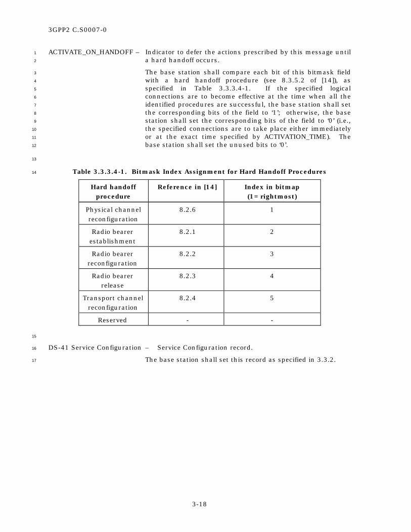
3GPP2 C.S0007-0
3-18
ACTIVATE_ON_HANDOFF – Indicator to defer the actions prescribed by this message until 1
a hard handoff occurs. 2
The base station shall compare each bit of this bitmask field 3
with a hard handoff procedure (see 8.3.5.2 of [14]), as 4
specified in Table 3.3.3.4-1. If the specified logical 5
connections are to become effective at the time when all the 6
identified procedures are successful, the base station shall set 7
the corresponding bits of the field to ‘1’; otherwise, the base 8
station shall set the corresponding bits of the field to ‘0’ (i.e., 9
the specified connections are to take place either immediately 10
or at the exact time specified by ACTIVATION_TIME). The 11
base station shall set the unused bits to ‘0’. 12
13
Table 3.3.3.4-1. Bitmask Index Assignment for Hard Handoff Procedures 14
Hard handoff procedure
Reference in [14] Index in bitmap (1= rightmost)
Physical channel reconfiguration
8.2.6 1
Radio bearer establishment
8.2.1 2
Radio bearer reconfiguration
8.2.2 3
Radio bearer release
8.2.3 4
Transport channel reconfiguration
8.2.4 5
Reserved - -
15
DS-41 Service Configuration – Service Configuration record. 16
The base station shall set this record as specified in 3.3.2. 17
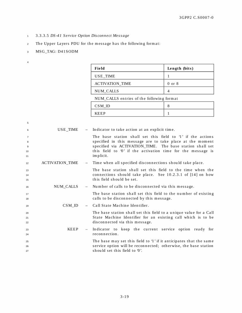
3GPP2 C.S0007-0
3-19
3.3.3.5 DS-41 Service Option Disconnect Message 1
The Upper Layers PDU for the message has the following format: 2
MSG_TAG: D41SODM 3
4
Field Length (bits)
USE_TIME 1
ACTIVATION_TIME 0 or 8
NUM_CALLS 4
NUM_CALLS entries of the following format
CSM_ID 8
KEEP 1
5
USE_TIME – Indicator to take action at an explicit time. 6
The base station shall set this field to ‘1’ if the actions 7
specified in this message are to take place at the moment 8
specified via ACTIVATION_TIME. The base station shall set 9
this field to ‘0’ if the activation time for the message is 10
implicit. 11
ACTIVATION_TIME – Time when all specified disconnections should take place. 12
The base station shall set this field to the time when the 13
connections should take place. See 10.2.3.1 of [14] on how 14
this field should be set. 15
NUM_CALLS – Number of calls to be disconnected via this message. 16
The base station shall set this field to the number of existing 17
calls to be disconnected by this message. 18
CSM_ID – Call State Machine Identifier. 19
The base station shall set this field to a unique value for a Call 20
State Machine Identifier for an existing call which is to be 21
disconnected via this message. 22
KEEP – Indicator to keep the current service option ready for 23
reconnection. 24
The base may set this field to ‘1’ if it anticipates that the same 25
service option will be reconnected; otherwise, the base station 26
should set this field to ‘0’. 27
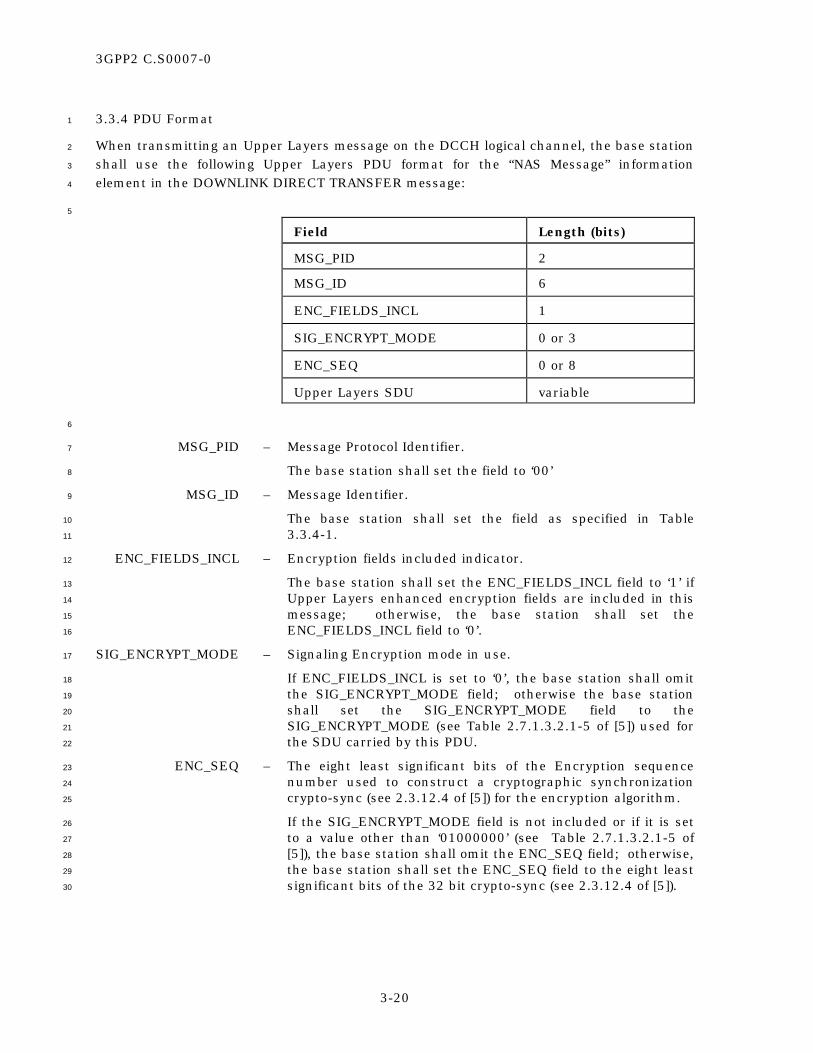
3GPP2 C.S0007-0
3-20
3.3.4 PDU Format 1
When transmitting an Upper Layers message on the DCCH logical channel, the base station 2
shall use the following Upper Layers PDU format for the “NAS Message” information 3
element in the DOWNLINK DIRECT TRANSFER message: 4
5
Field Length (bits)
MSG_PID 2
MSG_ID 6
ENC_FIELDS_INCL 1
SIG_ENCRYPT_MODE 0 or 3
ENC_SEQ 0 or 8
Upper Layers SDU variable
6
MSG_PID – Message Protocol Identifier. 7
The base station shall set the field to ‘00’ 8
MSG_ID – Message Identifier. 9
The base station shall set the field as specified in Table 10
3.3.4-1. 11
ENC_FIELDS_INCL – Encryption fields included indicator. 12
The base station shall set the ENC_FIELDS_INCL field to ‘1’ if 13
Upper Layers enhanced encryption fields are included in this 14
message; otherwise, the base station shall set the 15
ENC_FIELDS_INCL field to ‘0’. 16
SIG_ENCRYPT_MODE – Signaling Encryption mode in use. 17
If ENC_FIELDS_INCL is set to ‘0’, the base station shall omit 18
the SIG_ENCRYPT_MODE field; otherwise the base station 19
shall set the SIG_ENCRYPT_MODE field to the 20
SIG_ENCRYPT_MODE (see Table 2.7.1.3.2.1-5 of [5]) used for 21
the SDU carried by this PDU. 22
ENC_SEQ – The eight least significant bits of the Encryption sequence 23
number used to construct a cryptographic synchronization 24
crypto-sync (see 2.3.12.4 of [5]) for the encryption algorithm. 25
If the SIG_ENCRYPT_MODE field is not included or if it is set 26
to a value other than ‘01000000’ (see Table 2.7.1.3.2.1-5 of 27
[5]), the base station shall omit the ENC_SEQ field; otherwise, 28
the base station shall set the ENC_SEQ field to the eight least 29
significant bits of the 32 bit crypto-sync (see 2.3.12.4 of [5]). 30

3GPP2 C.S0007-0
3-21
Upper Layers SDU – The Upper Layer Message. 1
The mobile station shall set the field as specified in 3.3.3 of 2
this specification or in 3.7 of [5], as amended by 3.3.1 of this 3
specification. 4
5

3GPP2 C.S0007-0
3-22
Table 3.3.4-1. Identification of the Downlink Upper Layers Messages (part 1 of 2) 1
Message Name
MSG_TAG
MSG_ID
Reference in [5]:
Local Reference:
ANSI-41 RAND Message A41RANDM - 3.7.2.3.2.31 3.3.1.3
ANSI-41 System Parameters Message
A41SPM - 3.7.2.3.2.29 3.3.1.2
Authentication Challenge Message
AUCM ‘011000’ 3.7.3.3.2.2 -
Data Burst Message DBM ‘110000’ 3.7.3.3.2.4 -
DS-41 Call Request Message
D41CRM ‘000001’ - 3.3.3.1
DS-41 In-traffic System Parameters Message
D41ITSPM ‘111000’ - 3.3.3.2
DS-41 Release Message D41RELM ‘000010’ - 3.3.3.3
DS-41 Service Option Connect Message
D41SOCM ‘001000’ - 3.3.3.4
DS-41 Service Option Disconnect Message
D41SODM ‘001001’ - 3.3.3.5
Extended Alert With Information Message
EAWIM ‘000100’ 3.7.3.3.2.42 -
Extended Flash With Information Message
EFWIM ‘000011’ 3.7.3.3.2.43 -
Extended Global Service Redirection Message
EGSRM - 3.7.2.3.2.27 3.3.1.6
Feature Notification Message
FNM ‘101001’ 3.7.2.3.2.12 -
Mobile Station Registered Message
MSRM ‘010000’ 3.7.3.3.2.15 3.3.1.10
Order Message ORDM ‘111111’ 3.7.3.3.2.1 3.3.1.9
PACA Message PACAM ‘000101’ 3.7.2.3.2.20 -
Private Neighbor List Message
PNLM - 3.7.2.3.2.24 3.3.1.5
Security Mode Command Message
SMCM ‘100000’ 3.7.3.3.2.44 3.3.1.8
2

3GPP2 C.S0007-0
3-23
Table 3.3.4-1. Identification of the Downlink Upper Layers Messages (part 2 of 2) 1
Message Name
MSG_TAG
MSG_ID
Reference in [5]:
Local Reference:
Service Option Control Message
SOCM ‘001010’ 3.7.3.3.2.21 -
Service Redirection Message
SRDM ‘111110’ 3.7.3.3.2.23 -
Status Request Message STRQM ‘101000’ 3.7.3.3.2.16 3.3.1.7
SSD Update Message SSDUM ‘011001’ 3.7.3.3.2.13 -
TMSI Assignment Message
TASM ‘010001’ 3.7.3.3.2.22 -
User Zone Identification Message
UZIM - 3.7.2.3.2.23 3.3.1.4
2
The base station shall interpret Upper Layers PDU received from the mobile station 3
according to the formats described in 2.3.4. 4
When transmitting broadcast system information on the BCCH logical channel, the base 5
station shall use the Upper Layers SDU format (defined in 3.7 of [5], and amended by 3.3.1 6
of this specification) for the appropriate information elements (see Table 8.1.1 of [14] for a 7
description of information block characteristics), as follows: 8
9
Table 3.3.4-2. Broadcast System Information 10
Broadcast Information
Information Block
Information element
MIN_P_REV, P_REV, SID, NID from the Sync Channel Message
MIB MIN_P_REV, P_REV, SID, NID
ANSI-41 System Parameters Message
SIB 13 NAS (ANSI-41) System Information
ANSI-41 RAND Message SIB 13.1 ANSI-41 RAND Information
User Zone Identification Message SIB 13.2 ANSI-41 User Zone Identification Information
Private Neighbor List Message SIB 13.3 ANSI-41 Private Neighbor List Information
Extended Global Service Redirection Message
SIB 13.4 ANSI-41 Global Service Redirection Information
11

3GPP2 C.S0007-0
3-24
When transmitting a broadcast SMS message on the CTCH logical channel, the base station 1
shall use the following format for the “CB Data” information element in the BMC CBS 2
message: 3
4
Field Length (bits)
MSG_PID 2
MSG_ID 6
BC_ADDR 40
Upper Layers SDU variable
5
MSG_PID – Message Protocol Identifier. 6
The base station shall set the field to ‘00’ 7
MSG_ID – Message Identifier. 8
The base station shall set the field as specified in Table 9
3.3.4-1. 10
BC_ADDR – Broadcast Address. 11
The base station shall set the field as specified in [15]. 12
Upper Layers SDU – The Upper Layer message. 13
The mobile station shall set the field as specified in 3.3.3 of 14
this specification or in 3.7 of [5], as amended by 3.3.1 of this 15
specification. 16

3GPP2 C.S0007-0
A-1
ANNEX A RESERVED 1
2

3GPP2 C.S0007-0
A-2
No text. 1

3GPP2 C.S0007-0
B-1
ANNEX B INFORMATION FLOWS 1
This informative annex contains examples of information flows between the various 2
functional parts of a DS-41 system. 3
The conventions used in the information flows contained in this annex are as follows: 4
• RRC messages defined by 3GPP are in upper case, 5
e.g., RRC CONNECTION REQUEST. 6
• cdma2000 messages defined by 3GPP2 are italicized, 7
e.g., DS-41 Call Start-Up Message. 8
• Channels used to carry the specified message are indicated in parentheses, 9
e.g., (CCCH). 10
• Messages that are encapsulated within other messages are indicated in braces, 11
e.g., INITIAL DIRECT TRANSFER (DCCH) {DS-41 Call Start-Up Message}. 12
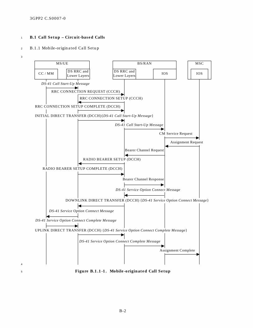
3GPP2 C.S0007-0
B-2
B.1 Call Setup – Circuit-based Calls 1
B.1.1 Mobile-originated Call Setup 2
3
MS/UE BS/RAN MSC
CC / MM DS RRC andLower Layers IOSDS RRC and
Lower Layers IOS
DS-41 Call Start-Up Message
RRC CONNECTION REQUEST (CCCH)
RRC CONNECTION SETUP (CCCH)
INITIAL DIRECT TRANSFER (DCCH){DS-41 Call Start-Up Message}
DS-41 Call Start-Up Message
CM Service Request
Assignment Request
Bearer Channel Request
RADIO BEARER SETUP (DCCH)
RADIO BEARER SETUP COMPLETE (DCCH)
Bearer Channel Response
DOWNLINK DIRECT TRANSFER (DCCH) {DS-41 Service Option Connect Message}
DS-41 Service Option Connect Complete Message
Assignment Complete
RRC CONNECTION SETUP COMPLETE (DCCH)
DS-41 Service Option Connect Message
DS-41 Service Option Connect Message
DS-41 Service Option Connect Complete Message
UPLINK DIRECT TRANSFER (DCCH) {DS-41 Service Option Connect Complete Message}
4
Figure B.1.1-1. Mobile-originated Call Setup 5

3GPP2 C.S0007-0
B-3
B.1.2 Mobile-terminated Call Setup 1
2
MS/UE BS/RAN MSC
CC / MMDS RRC andLower Layers IOSDS RRC and
Lower Layers IOS
DS-41 Call Start-Up Message
UPLINK DIRECT TRANSFER (DCCH) {DS-41 Call Start-Up Message}
DS-41 Call Start-Up Message
Paging Response
Assignment Request
Bearer Channel Request
RADIO BEARER SETUP (DCCH)
RADIO BEARER SETUP COMPLETE (DCCH)
Bearer Channel Response
Paging Request
DS-41 Call Request Message
PAGING TYPE 1 (PCH)
RRC CONNECTION REQUEST (CCCH)
RRC CONNECTION SETUP (CCCH)
RRC CONNECTION SETUP COMPLETE (DCCH)
DOWNLINK DIRECT TRANSFER (DCCH) {DS-41 Call Request Message}
DS-41 Call Request Message
Information Flow Continues onthe Next Page
3
4

3GPP2 C.S0007-0
B-4
1
MS/UE BS/RAN MSC
CC / MMDS RRC andLower Layers IOSDS RRC and
Lower Layers IOS
Information Flow Continuedfrom the Previous Page DS-41 Service Option Connect Message
DOWNLINK DIRECT TRANSFER (DCCH) {DS-41 Service Option Connect Message}
DS-41 Service Option Connect Message
DS-41 Service Option Connect Complete Message
UPLINK DIRECT TRANSFER (DCCH) {DS-41 Service Option Connect Complete Message}
DS-41 Service Option Connect Complete Message
Assignment Complete
Connect Order
UPLINK DIRECT TRANSFER (DCCH) {Connect Order}
Connect Order
Connect
Extended Alert with Information Message
DOWNLINK DIRECT TRANSFER (DCCH) {Extended Alert with Information Message}
Extended Alert with Information Message
2
Figure B.1.2-1. Mobile-terminated Call Setup 3

3GPP2 C.S0007-0
B-5
B.2 Call Clearing – Circuit-based Calls 1
The following sections contain example scenarios of call clearing in a DS-41 system when a 2
single call instance exists. 3
B.2.1 MS-initiated Call Clearing – Circuit-based Call 4
5
MS/UE MSC
CC / MM DS RRC andLower Layers
CC / MMto/from IOS
DS RRC andLower Layers
IOS
BS/RAN
DS-41 Release Message
UPLINK DIRECT TRANSFER (DCCH) {DS-41 Release Message}
DS-41 Release Message
Clear Request
DS-41 Release Message
DOWNLINK DIRECT TRANSFER (DCCH) {DS-41 Release Message}
DS-41 Release Message
Clear Command
Release All Connections
Release All Connections Ack
RRC CONNECTION RELEASE (DCCH)
RRC CONNECTION RELEASE COMPLETE (DCCH)
Clear Complete
6
Figure B.2.1-1. Mobile-initiated Call Clearing – Circuit-based Call 7

3GPP2 C.S0007-0
B-6
B.2.2 BS- and MSC-initiated Call Clearing – Circuit-based Call 1
The following information flow is an example of circuit-based call clearing initiated by either 2
the MSC or the BS/RAN. The only difference in the two flows is the first message. The 3
Clear Request message is used by the BS/RAN to request call clearing and is followed by 4
the Clear Command message from the MSC. When the MSC wishes to clear a call, it 5
immediately issues the Clear Command message and the remainder of the information flow 6
is then identical in both call clearing situations. 7
8
MS/UE MSC
CC / MMDS RRC andLower Layers
CC / MMto/from IOS
DS RRC andLower Layers
IOS
BS/RAN
DS-41 Release Message
UPLINK DIRECT TRANSFER (DCCH) {DS-41 Release Message}
DS-41 Release Message
Clear Request
DS-41 Release Message
DOWNLINK DIRECT TRANSFER (DCCH) {DS-41 Release Message}
DS-41 Release Message
Clear Command
Release All Connections
Release All Connections Ack
RRC CONNECTION RELEASE (DCCH)
RRC CONNECTION RELEASE COMPLETE (DCCH)
Clear Complete
9
Figure B.2.2-1. BS- and MSC-initiated Call Clearing – Circuit-based Call 10

3GPP2 C.S0007-0
B-7
B.2.3 PDSN-initiated Call Clearing – Packet Call 1
2
MS/UE
CC / MMDS RRC,
L2, L1
BS/RAN
IOSDS RRC,L2, L1
MSC
IOS
DS-41 Release Message
UPLINK DIRECT TRANSFER (DCCH) {DS-41 Release Message}
DS-41 Release Message
Clear Request
DS-41 Release Message
DOWNLINK DIRECT TRANSFER (DCCH) {DS-41 Release Message}
DS-41 Release Message
Clear Command
Release All Connections
Release All Connections Ack
RRC CONNECTION RELEASE (DCCH)
RRC CONNECTION RELEASE COMPLETE (DCCH)
Clear Complete
PCF PDSN
A10/A11Clearing
Procedure
A8/A9 ClearingProcedure
PacketData
3
Figure B.2.3-1. PDSN-initiated Call Clearing – Packet Call 4
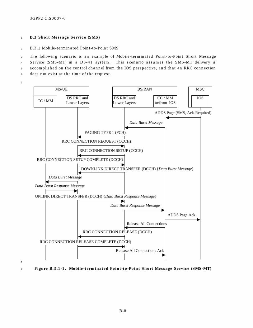
3GPP2 C.S0007-0
B-8
B.3 Short Message Service (SMS) 1
B.3.1 Mobile-terminated Point-to-Point SMS 2
The following scenario is an example of Mobile-terminated Point-to-Point Short Message 3
Service (SMS-MT) in a DS-41 system. This scenario assumes the SMS-MT delivery is 4
accomplished on the control channel from the IOS perspective, and that an RRC connection 5
does not exist at the time of the request. 6
7
MS/UE MSC
CC / MMDS RRC andLower Layers
CC / MMto/from IOS
DS RRC andLower Layers
IOS
BS/RAN
Data Burst Response Message
UPLINK DIRECT TRANSFER (DCCH) {Data Burst Response Message}
Data Burst Response Message
ADDS Page Ack
ADDS Page (SMS, Ack-Required)
Data Burst Message
PAGING TYPE 1 (PCH)
RRC CONNECTION REQUEST (CCCH)
RRC CONNECTION SETUP (CCCH)
RRC CONNECTION SETUP COMPLETE (DCCH)
DOWNLINK DIRECT TRANSFER (DCCH) {Data Burst Message}
Data Burst Message
RRC CONNECTION RELEASE (DCCH)
RRC CONNECTION RELEASE COMPLETE (DCCH)
Release All Connections
Release All Connections Ack
8
Figure B.3.1-1. Mobile-terminated Point-to-Point Short Message Service (SMS-MT) 9
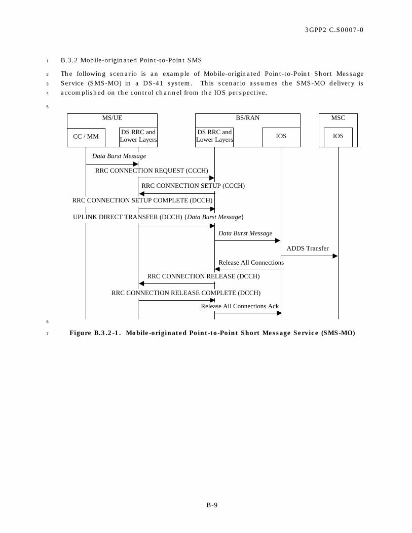
3GPP2 C.S0007-0
B-9
B.3.2 Mobile-originated Point-to-Point SMS 1
The following scenario is an example of Mobile-originated Point-to-Point Short Message 2
Service (SMS-MO) in a DS-41 system. This scenario assumes the SMS-MO delivery is 3
accomplished on the control channel from the IOS perspective. 4
5
BS/RANMS/UE MSC
CC / MMDS RRC andLower Layers IOSDS RRC and
Lower Layers IOS
Data Burst Message
UPLINK DIRECT TRANSFER (DCCH) {Data Burst Message}
Data Burst Message
ADDS Transfer
RRC CONNECTION REQUEST (CCCH)
RRC CONNECTION SETUP (CCCH)
RRC CONNECTION SETUP COMPLETE (DCCH)
RRC CONNECTION RELEASE (DCCH)
RRC CONNECTION RELEASE COMPLETE (DCCH)
Release All Connections
Release All Connections Ack
6
Figure B.3.2-1. Mobile-originated Point-to-Point Short Message Service (SMS-MO) 7

3GPP2 C.S0007-0
B-10
B.3.3 Broadcast SMS 1
The following scenario is an example of Cell Broadcast Short Message Service: 2
• For Broadcast SMS, the DS-41 system uses the delivery mechanism provided by the 3
RRC sublayer via the 3GPP Broadcast/Multicast Control (BMC) protocol as defined 4
in [27] and [13]. 5
• The repetition of the broadcast message may be done via the MSC. Each repetition 6
would result in the following scenario being executed. 7
• The Data Burst Message (defined in [5]) that carries the broadcast SMS (defined in 8
[15]) is encapsulated in the BMC CBS message by the BMC at the RAN. Upon 9
receiving the BMC message, the mobile station DS RRC layer delivers the Data Burst 10
Message to the upper layer cdma2000 broadcast SMS application. 11
12
MSC
IOS
MS/UE BS/RAN
DS RRC BMCBMC BM-IWFDS RRCBroadcastSMS Appl.
Data Burst Message
Data Burst MessageADDS Page (SMS-CB) (repeat)
Data Burst Message
BMC SCHEDULE MESSAGE (FACH)
BMC CBS MESSAGE (FACH) {Data Burst Message}
Data Burst Message
BCH-SYS INFO(with CB config) (BCCH)ADDS Page (SMS-CB)
BMC CBS MESSAGE (FACH) {Data Burst Message}
BCH-SYS INFO(with CB config) (BCCH)
13
Figure B.3.3-1. Cell Broadcast Short Message Service 14

3GPP2 C.S0007-0
B-11
B.4 SSD Update 1
The following scenario shows the message exchange necessary to accomplish Shared Secret 2
Data (SSD) Update in the mobile station (MS/UE). From the perspective of the IOS 3
protocol, this procedure is carried out on the control channel, even though the DS radio 4
layers perform the messaging over the RRC connection. 5
6
BS/RANMS/UE MSC
CC / MMDS RRC andLower Layers IOSDS RRC and
Lower Layers IOS
Base Station Challenge Order Message
UPLINK DIRECT TRANSFER (DCCH) {Base Station Challenge Order Message}
Base Station Challenge Order Message
Base Station Challenge Request
SSD Update Request
SSD Update Message
PAGING TYPE 1 (PCH)
RRC CONNECTION REQUEST (CCCH)
RRC CONNECTION SETUP (CCCH)
RRC CONNECTION SETUP COMPLETE (DCCH)
DOWNLINK DIRECT TRANSFER (DCCH) {SSD Update Message}
SSD Update Message
Base Station Challenge Response
Base Station Challenge Confirmation Order Message
DOWNLINK DIRECT TRANSFER (DCCH) {Base Station Challenge Confirmation Order Message}
Base Station Challenge Confirmation Order Message
Continued on thenext page
7
8

3GPP2 C.S0007-0
B-12
1
MS/UE BS/RAN MSC
CC / MM DS RRC andLower Layers IOSDS RRC and
Lower Layers IOS
Continued from theprevious page
Release All Connections
Release All Connections Ack
RRC CONNECTION RELEASE (DCCH)
RRC CONNECTION RELEASE COMPLETE (DCCH)
SSD Update Confirmation Order Message
UPLINK DIRECT TRANSFER (DCCH) {SSD Update Confirmation Order Message}
SSD Update Confirmation Order Message
SSD Update Response
2
Figure B.4-1. SSD Update in a DS-41 System 3

3GPP2 C.S0007-0
B-13
B.5 OTASP and OTAPA 1
OTASP (Over-The-Air Service Provisioning) involves establishing a voice call and then 2
sending signaling messages to the mobile station using ADDS Deliver messages on the IOS 3
A1 interface. 4
OTAPA (Over-The-Air Parameter Administration) involves sending application level 5
messaging between the network and the mobile station. This is performed on a traffic 6
channel using ADDS Deliver messages on the IOS A1 interface. 7
The following scenario is an example of OTASP and OTAPA support in a DS-41 system. It is 8
assumed that a traffic channel has already been established between the mobile station and 9
the network. The scenario shows two activities that are considered independent by the IOS 10
and DS layers, but may be related at the application layer (for example, a message from the 11
network to the mobile station followed by a reply from the mobile station to the network). 12
13
BS/RANMS/UE MSC
CC / MMDS RRC,
L2, L1 IOSDS RRC,L2, L1 IOS
UPLINK DIRECT TRANSFER (DCCH) {Data Burst Response Message}
Data Burst Response Message
DOWNLINK DIRECT TRANSFER (DCCH) {Data Burst Message}
Data Burst Message
ADDS Deliver (OTA Message, Ack Required)
ADDS Deliver Ack
Data Burst Message
Separate Mobile-originated Activity Shown Below
UPLINK DIRECT TRANSFER (DCCH) {Data Burst Message}
Data Burst Message
ADDS Deliver (OTA Message)
Data Burst Message
Data Burst Response Message
14
Figure B.5-1. OTASP and OTAPA Support 15
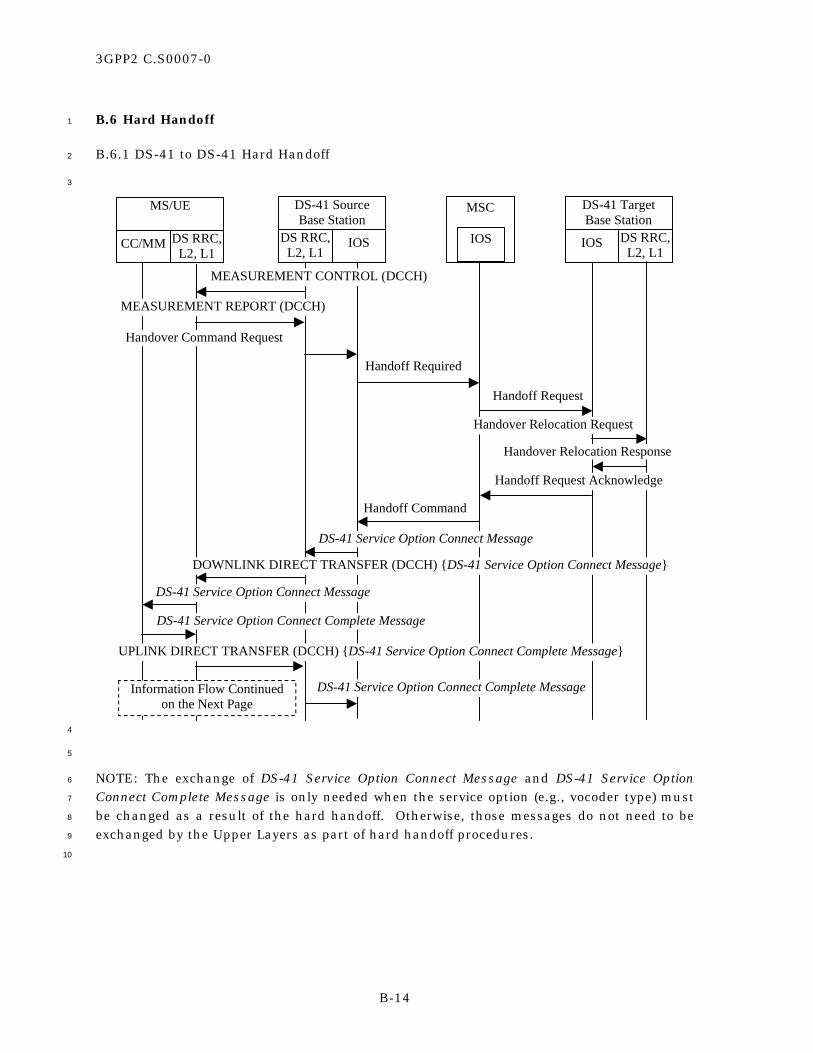
3GPP2 C.S0007-0
B-14
B.6 Hard Handoff 1
B.6.1 DS-41 to DS-41 Hard Handoff 2
3
MS/UE
CC/MM DS RRC,L2, L1
DS-41 SourceBase Station
DS RRC,L2, L1
IOS
DS-41 TargetBase Station
IOS DS RRC,L2, L1
MSC
IOS
MEASUREMENT CONTROL (DCCH)
MEASUREMENT REPORT (DCCH)
Handover Command Request
Handoff Required
Handoff Request
Handover Relocation Request
Handover Relocation Response
Handoff Command
Handoff Request Acknowledge
Information Flow Continuedon the Next Page
DS-41 Service Option Connect Message
DOWNLINK DIRECT TRANSFER (DCCH) {DS-41 Service Option Connect Message}
DS-41 Service Option Connect Message
DS-41 Service Option Connect Complete Message
DS-41 Service Option Connect Complete Message
UPLINK DIRECT TRANSFER (DCCH) {DS-41 Service Option Connect Complete Message}
4
5
NOTE: The exchange of DS-41 Service Option Connect Message and DS-41 Service Option 6
Connect Complete Message is only needed when the service option (e.g., vocoder type) must 7
be changed as a result of the hard handoff. Otherwise, those messages do not need to be 8
exchanged by the Upper Layers as part of hard handoff procedures. 9
10

3GPP2 C.S0007-0
B-15
1
MS/UE
CC/MM DS RRC,L2, L1
DS-41 SourceBS/RAN
DS RRC,L2, L1
IOS
DS-41 TargetBS/RAN
IOS DS RRC,L2, L1
MSC
IOS
RAB Release Response
Clear Complete
Handover Completion
Clear Command
Handoff Complete
RAB Release Request
DS Radio Connection Establishment
Information Flow Continuedfrom the Previous Page
Handover Command Response
PHYSICAL CHANNEL RECONFIGURATION (DCCH)
Handoff Commenced
PHYSICAL CHANNEL RECONFIGURATION COMPLETE (DCCH)
2
Figure B.6.1-1. DS-41 to DS-41 Hard Handoff 3

3GPP2 C.S0007-0
B-16
B.6.2 DS-41 to MC-41 Hard Handoff 1
2
DS-41 SourceBS/RAN
DS RRC,L2, L1
IOS
MC-41 TargetBS/RAN
IOS
MSC
IOS
MEASUREMENT CONTROL (DCCH)
MEASUREMENT REPORT (DCCH)
Handover Command Request
Handoff Required
Handoff Request
Handoff Command
Handoff Request Acknowledge
MC RRC,L2, L1
MS/UE
CC/MM
DS RRC,L2, L1
MC RRC,L2, L1
UE CAPABILITY ENQUIRY (DCCH)
UE CAPABILITY INFORMATION (DCCH)
UE CAPABILITY INFORMATION CONFIRM (DCCH)
RAB Release Response
Clear Complete
Clear Command
Handoff Complete
RAB Release Request
MC Radio Connection Establishment
INTERSYSTEM HANDOVER COMMAND (DCCH) {Universal Handoff Direction Message}
Handoff Commenced
Handover Command Response
3
Figure B.6.2-1. DS-41 to MC-41 Hard Handoff 4

3GPP2 C.S0007-0
B-17
B.6.3 DS-41 to Analog Hard Handoff 1
2
DS-41 SourceBS/RAN
DS RRC,L2, L1
IOS
Analog TargetBS/RAN
IOS
MSC
IOS
MEASUREMENT CONTROL (DCCH)
MEASUREMENT REPORT (DCCH)
Handover Command Request
Handoff Required
Handoff Request
Handoff Command
Handoff Request Acknowledge
MC RRC,L2, L1
MS/UE
CC/MM
DS RRC,L2, L1
MC RRC,L2, L1
UE CAPABILITY ENQUIRY (DCCH)
UE CAPABILITY INFORMATION (DCCH)
UE CAPABILITY INFORMATION CONFIRM (DCCH)
RAB Release Response
Clear Complete
Clear Command
Handoff Complete
RAB Release Request
Analog Radio Connection Establishment
INTERSYSTEM HANDOVER COMMAND (DCCH) {Analog Handoff Direction Message}
Handoff Commenced
Handover Command Response
3
Figure B.6.3-1. DS-41 to Analog Hard Handoff 4

3GPP2 C.S0007-0
B-18
B.6.4 DS-41 to DS-41 – Inter-MSC Hard Handoff 1
2
MS/UE
CC/MM DS RRC,L2, L1
DS-41 SourceBS/RAN
DS RRC,L2, L1
IOS
DS-41 TargetBS/RAN
IOS DS RRC,L2, L1
SourceMSC
IOS
MEASUREMENT CONTROL (DCCH)
MEASUREMENT REPORT (DCCH)
Handover Command Request
Handoff Required
Handoff Request
Handover Relocation Request
Handover Relocation Response
Handoff Command
Handoff Request Acknowledge
Information Flow Continuedon the Next Page
ANSI-41
TargetMSC
ANSI-41
IOS
Facilities Directive 2
Facilities Directive 2 Ack
DOWNLINK DIRECT TRANSFER (DCCH) {DS-41 Service Option Connect Message}
DS-41 Service Option Connect Message
DS-41 Service Option Connect Message
DS-41 Service Option Connect Complete Message
UPLINK DIRECT TRANSFER (DCCH) {DS-41 Service Option Connect Complete Message}
DS-41 Service Option Connect Complete Message
3
4
NOTE: The exchange of DS-41 Service Option Connect Message and DS-41 Service Option 5
Connect Complete Message is only needed when the service option (e.g., vocoder type) must 6
be changed as a result of the hard handoff. Otherwise, those messages do not need to be 7
exchanged by the Upper Layers as part of hard handoff procedures. 8
9
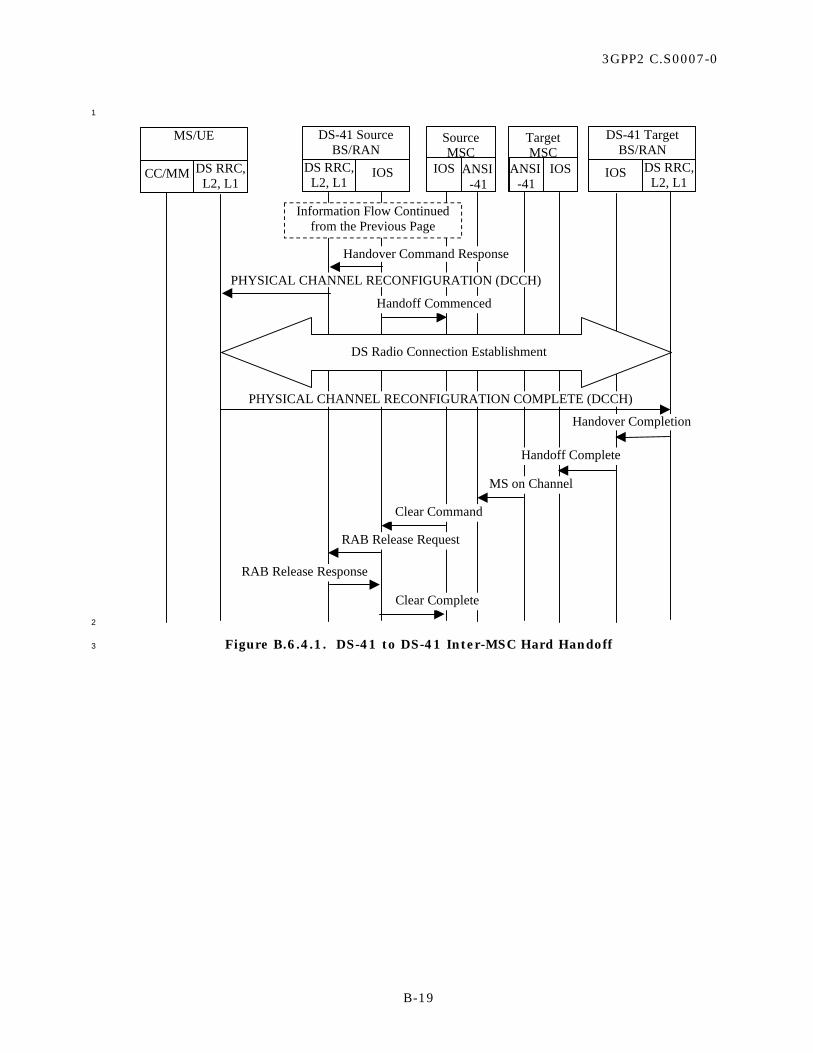
3GPP2 C.S0007-0
B-19
1
MS/UE
CC/MM DS RRC,L2, L1
DS-41 SourceBS/RAN
DS RRC,L2, L1
IOS
DS-41 TargetBS/RAN
IOS DS RRC,L2, L1
Information Flow Continuedfrom the Previous Page
SourceMSC
IOS ANSI-41
TargetMSC
ANSI-41
IOS
RAB Release Response
Clear Complete
Handover Completion
Clear Command
Handoff Complete
RAB Release Request
MS on Channel
DS Radio Connection Establishment
Handover Command Response
PHYSICAL CHANNEL RECONFIGURATION (DCCH)
Handoff Commenced
PHYSICAL CHANNEL RECONFIGURATION COMPLETE (DCCH)
2
Figure B.6.4.1. DS-41 to DS-41 Inter-MSC Hard Handoff 3

3GPP2 C.S0007-0
B-20
B.7 Packet Data Calls 1
This section contains references to the packet control function (PCF), packet data service 2
node (PDSN), and A8, A9, A10 and A11 connections. The reader is directed to [16] for 3
further information. 4
B.7.1 Origination and Packet Registration 5
The following scenario is an example of packet data origination and registration in a DS-41 6
system. 7
This same scenario applies to re-registration when the mobile is in a dormant state and 8
enters a new packet zone area (i.e., an area served by a different PCF which must connect 9
to a PDSN). 10
11
MSC
IOS(A1)
DS-41 Call Start-Up Message
RRC CONNECTION REQUEST (CCCH)
RRC CONNECTION SETUP (CCCH)
UPLINK DIRECT TRANSFER (DCCH) {DS-41 Call Start-Up Message}
DS-41 Call Start-Up Message
CM Service Request
Assignment Request
Bearer Channel Request
RADIO BEARER SETUP (DCCH)
RADIO BEARER SETUP COMPLETE (DCCH)
Bearer Channel Response
RRC CONNECTION SETUP COMPLETE (DCCH)
MS/UE
CC /MM
DS RRC andLower Layers
MobileStation
PCF
BS/RAN
DS RRC andLower Layers
CC/MM
PacketData
(A8/A9)
PDSN
IOS(A10/A11
)
PCF
IOS(A8/A9)
IOS(A10/A11)
This information flow iscontinued on the next page.
12
13

3GPP2 C.S0007-0
B-21
1
MSC
IOS(A1)
MS/UE
CC /MM
DS RRC andLower Layers
MobileStation
PCF
BS/RAN
DS RRC andLower Layers
CC/MM
PacketData
(A8/A9)
PDSN
IOS(A10/A11
)
PCF
IOS(A8/A9)
IOS(A10/A11)
DS-41 Service Option Connect Message
DOWNLINK DIRECT TRANSFER (DCCH) {DS-41 Service Option Connect Message}
Assignment Complete
A8/A9 Connection Establishment
A10/A11Conn.Estab.
Packet Data Registration and Connection Establishment
This information flow is continuedfrom the previous page.
Packet Data Information Flow
DS-41 Service Option Connect Message
DS-41 Service Option Connect Complete Message
UPLINK DIRECT TRANSFER (DCCH) {DS-41 Service Option Connect Complete Message}
DS-41 Service Option Connect Complete Message
2
Figure B.7.1-1. Packet Data – Mobile-originated Registration and Call Setup 3

3GPP2 C.S0007-0
B-22
B.7.2 Entering Dormant State 1
The following scenario is an example of a packet call entering the dormant state in a DS-41 2
system. 3
4
MSC
IOS(A1)
MS/UE
CC /MM
DS RRC andLower Layers
MobileStation
PCF
BS/RAN
DS RRC andLower Layers
CC/MM
PacketData
(A8/A9)
PDSN
IOS(A10/A11
)
PCF
IOS(A8/A9)
IOS(A10/A11)
DS-41 Service Option Connect Complete Message
Clear Request
DS-41 Service Option Disconnect Message
DOWNLINK DIRECT TRANSFER (DCCH) {DS-41 Service Option Disconnect Message}
DS-41 Service Option Disconnect Message
Clear Command
Release Radio Bearer
Release Radio Bearer Ack
RADIO BEARER RELEASE (DCCH)
RADIO BEARER RELEASE COMPLETE (DCCH)
Clear Complete
A8/A9 Connections Released A10/A11Connections
Kept
UPLINK DIRECT TRANSFER (DCCH) {DS-41 Service Option Connect Complete Message}
DS-41 Service Option Connect Complete Message
5
Figure B.7.2-1. Packet Data – Call Enters Dormant State 6

3GPP2 C.S0007-0
B-23
B.7.3 Packet Data Call Network Re-Activation 1
The following scenario is an example of packet data call re-activation by the network. This 2
scenario assumes that the mobile station is still within the service area of the BS where it 3
was last connected to the network. 4
5 MSC
IOS(A1)
Mobile Station (UE)
CC /MM
DS RRC andLower Layers
MobileStation
PCF
BSC
DS RRC andLower Layers
CC/MM
PacketData
(A8/A9)
PDSN
IOS(A10/A11
)
PCF
IOS(A8/A9)
IOS(A10/A11)
BS Service Response
DataArrives at
PCFA8/A9 Connection
Establishment
BS Service Request
Paging Request
DS-41 Service Option Connect Message
DOWNLINK DIRECT TRANSFER (DCCH) {DS-41 Service Option Connect Message}
DS-41 Service Option Connect Message
DS-41 Service Option Connect Complete Message
UPLINK DIRECT TRANSFER (DCCH) {DS-41 Service Option Connect Complete Message}
DS-41 Service Option Connect Complete Message
Assignment Request
Paging Response
Assignment Complete
Packet Data Information Flow
Activate RRC Connection Request
PAGING TYPE 1 (PCH)
PHYSICAL CHANNEL RECONFIGURATION (DCCH)
PHYSICAL CHANNEL RECONFIGURATION COMPLETE (DCCH)
MEASUREMENT REPORT (DCCH)
Activate RRC Connection Response
Reconfiguration Request
Reconfiguration Response
6
Figure B.7.3-1. Packet Data – Network Re-Activation 7
8

3GPP2 C.S0007-0
B-24
No text. 1

3GPP2 C.S0007-0
C-1
ANNEX C DS-41 SUPPORT IN [5] 1
C.1 Procedures 2
When operating in MC-41 mode, dual-mode DS-41/MC-41 base stations and mobile 3
stations shall be able to send and receive the DS-41 Inter-system Transfer Message on the 4
f-dsch. To initiate inter-system handoff procedures to a DS-41 system, the base station 5
should send the DS-41 Inter-system Transfer Message with the PAYLOAD_MESSAGE field 6
set to one of the following messages: 7
• MEASUREMENT CONTROL message, 8
• HANDOVER TO UTRAN COMMAND message, 9
• UE CAPABILITY ENQUIRY message, 10
• UE CAPABILITY INFORMATION CONFIRM message. 11
When operating in MC-41 mode, dual-mode DS-41/MC-41 mobile stations and base 12
stations shall be able to send and receive the DS-41 Inter-system Transfer Message on the 13
r-dsch. Dual-mode DS-41/MC-41 mobile stations shall respond to the received DS-41 14
Inter-system Transfer Message, if required, by sending a DS-41 Inter-system Transfer 15
Message with the PAYLOAD_MESSAGE field set to one of the following messages, as 16
appropriate: 17
• ME ASUREMENT REPORT message, 18
• MEASUREMENT CONTROL FAILURE message, 19
• UE CAPABILITY INFORMATION message. 20
C.2 DS-41 Inter-system Transfer Message 21
The Layer 3 PDU for the message has the following format: 22
MSG_TAG: D41ISTM 23
MSG_TYPE: ‘00100001’ on r-dsch and ‘00101001’ on f-dsch. 24
25
Field Length (bits)
RADIO_INTERFACE_TYPE_ID 4
CORE_NETWORK_ID 4
PAYLOAD_MESSAGE_LENGTH 16
PAYLOAD_MESSAGE PAYLOAD_MESSAGE_LENGTH x 8
26
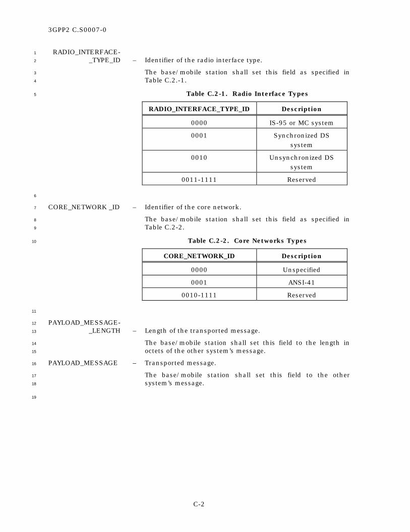
3GPP2 C.S0007-0
C-2
RADIO_INTERFACE- 1
_TYPE_ID – Identifier of the radio interface type. 2
The base/mobile station shall set this field as specified in 3
Table C.2.-1. 4
Table C.2-1. Radio Interface Types 5
RADIO_INTERFACE_TYPE_ID Description
0000 IS-95 or MC system
0001 Synchronized DS system
0010 Unsynchronized DS system
0011-1111 Reserved
6
CORE_NETWORK _ID – Identifier of the core network. 7
The base/mobile station shall set this field as specified in 8
Table C.2-2. 9
Table C.2-2. Core Networks Types 10
CORE_NETWORK_ID Description
0000 Unspecified
0001 ANSI-41
0010-1111 Reserved
11
PAYLOAD_MESSAGE- 12
_LENGTH – Length of the transported message. 13
The base/mobile station shall set this field to the length in 14
octets of the other system’s message. 15
PAYLOAD_MESSAGE – Transported message. 16
The base/mobile station shall set this field to the other 17
system’s message. 18
19

3GPP2 C.S0007-0
C-3
C.3 Service Redirection to DS-41 Systems 1
C.3.1 Changes to 3.7.2.3.2.16 of [5] 2
[…] 3
4
Description
RECORD_TYPE(binary)
NDSS off indication 00000000
Redirection to an AMPS/NAMPS analog system
00000001
Redirection to a CDMA system 00000010
Redirection to a TACS analog system 00000011
Redirection to a JTACS analog system 00000100
Redirection to a DS-41 system 00000101
All other RECORD_TYPE values are reserved
5
C.3.2 Procedures 6
When the base station sends a redirection record in the Service Redirection Message or 7
Extended Global Service Redirection Message that redirects to a DS system, the base station 8
shall set RECORD_TYPE of the redirection to ‘00000101’ and shall set the redirection record 9
type-specific fields to the following record: 10
11
Subfield Length (bits)
EXPECTED_SID 15
EXPECTED_NID 16
RESERVED 4
NUM_UARFCN 4
NUM_UARFCN occurrences of the following record:
RESERVED 5
UARFCN 9
BANDWIDTH 3
RESERVED 0–7 (as needed)
12

3GPP2 C.S0007-0
C-4
EXPECTED_SID – Expected SID. 1
If the base station is redirecting the mobile station to a 2
specific system, the base station shall set this field to the SID 3
of that system; otherwise, the base station shall set this field 4
to ‘0’. 5
EXPECTED_NID – Expected NID. 6
If the base station is redirecting the mobile station to a 7
specific network, the base station shall set this field to the 8
NID of that network; otherwise, the base station shall set this 9
field to 65535. 10
RESERVED – Reserved bits. 11
The base station shall set this field to ‘0000’ 12
NUM_UARFCN – Number of frequencies. 13
The base station shall set this field to the number of 14
frequencies in this record. 15
For each frequency on which the mobile station is to attempt to acquire a DS system, the 16
base station shall include one occurrence of the following record specifying the associated 17
frequency and bandwidth. 18
RESERVED – Reserved bits. 19
The base station shall set this field to ‘00000’ 20
UARFCN – Frequency. 21
The base station shall set this field to the frequency of the DS 22
system as specified in [19]. 23
BANDWIDTH – Bandwidth. 24
The base station shall set this field to the bandwidth of the DS 25
system as specified in the 3GPP specifications. 26
RESERVED – Reserved bits. 27
The base station shall add reserved bits as needed in order to 28
make the length of the record equal to an integer number of 29
octets. The base station shall set these bits to ‘0’. 30
31
C.4 Handoff to DS-41 Systems 32
C.4.1 Idle Handoff to DS-41 Systems 33
When operating in the MC-41 idle mode, dual-mode DS-41/MC-41 mobile stations should 34
be able to receive DS neighbor cell information in the Universal Neighbor List Message (see 35
C.4.1.1). 36
When operating in MC-41 mode, dual-mode DS-41/MC-41 base stations should be able to 37
send DS neighbor cell information in the Universal Neighbor List Message. 38
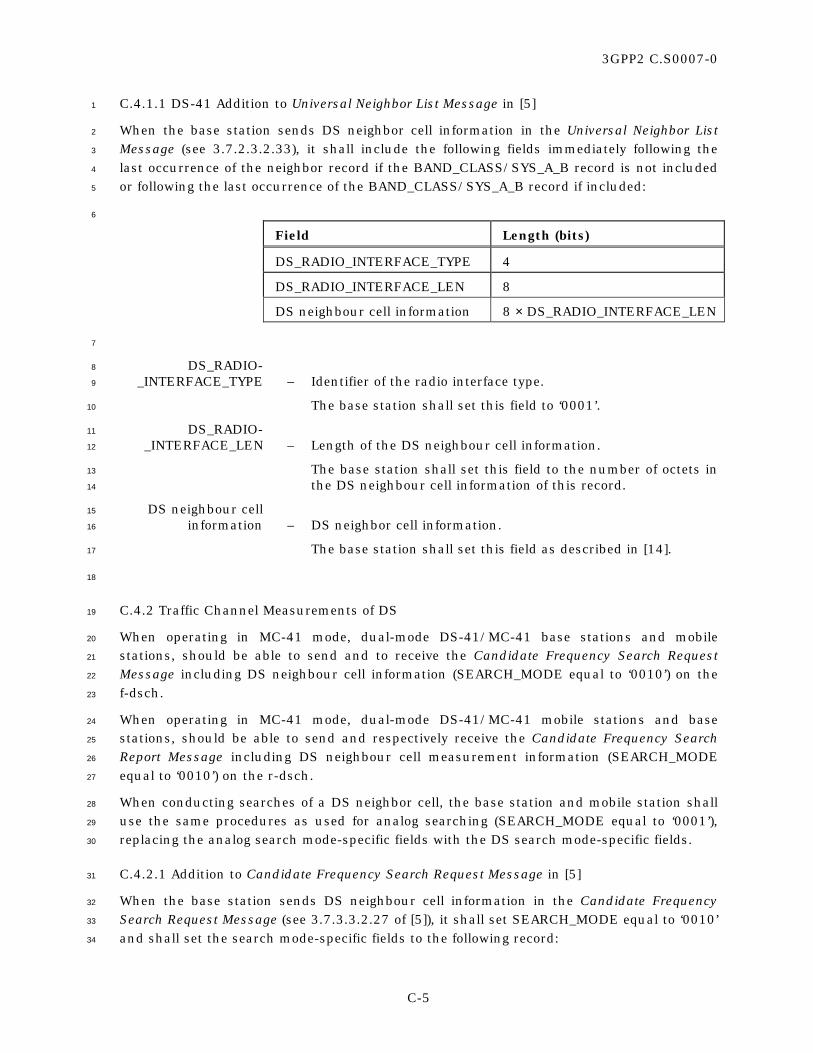
3GPP2 C.S0007-0
C-5
C.4.1.1 DS-41 Addition to Universal Neighbor List Message in [5] 1
When the base station sends DS neighbor cell information in the Universal Neighbor List 2
Message (see 3.7.2.3.2.33), it shall include the following fields immediately following the 3
last occurrence of the neighbor record if the BAND_CLASS/SYS_A_B record is not included 4
or following the last occurrence of the BAND_CLASS/SYS_A_B record if included: 5
6
Field Length (bits)
DS_RADIO_INTERFACE_TYPE 4
DS_RADIO_INTERFACE_LEN 8
DS neighbour cell information 8 × DS_RADIO_INTERFACE_LEN
7
DS_RADIO- 8
_INTERFACE_TYPE – Identifier of the radio interface type. 9
The base station shall set this field to ‘0001’. 10
DS_RADIO- 11
_INTERFACE_LEN – Length of the DS neighbour cell information. 12
The base station shall set this field to the number of octets in 13
the DS neighbour cell information of this record. 14
DS neighbour cell 15
information – DS neighbor cell information. 16
The base station shall set this field as described in [14]. 17
18
C.4.2 Traffic Channel Measurements of DS 19
When operating in MC-41 mode, dual-mode DS-41/MC-41 base stations and mobile 20
stations, should be able to send and to receive the Candidate Frequency Search Request 21
Message including DS neighbour cell information (SEARCH_MODE equal to ‘0010’) on the 22
f-dsch. 23
When operating in MC-41 mode, dual-mode DS-41/MC-41 mobile stations and base 24
stations, should be able to send and respectively receive the Candidate Frequency Search 25
Report Message including DS neighbour cell measurement information (SEARCH_MODE 26
equal to ‘0010’) on the r-dsch. 27
When conducting searches of a DS neighbor cell, the base station and mobile station shall 28
use the same procedures as used for analog searching (SEARCH_MODE equal to ‘0001’), 29
replacing the analog search mode-specific fields with the DS search mode-specific fields. 30
C.4.2.1 Addition to Candidate Frequency Search Request Message in [5] 31
When the base station sends DS neighbour cell information in the Candidate Frequency 32
Search Request Message (see 3.7.3.3.2.27 of [5]), it shall set SEARCH_MODE equal to ‘0010’ 33
and shall set the search mode-specific fields to the following record: 34

3GPP2 C.S0007-0
C-6
1
Field Length (bits)
SF_TOTAL_EC_THRESH 5
SF_TOTAL_EC_IO_THRESH 5
RESERVED 6
DS neighbour cell information Variable length
2
SF_TOTAL_EC- 3
_THRESH – Serving Frequency total pilot Ec threshold. 4
If the mobile station is not to use the measurement of total Ec 5
of the pilots in the Serving Frequency Active Set in the DS 6
periodic search procedure, the base station shall set this field 7
to ‘11111’; otherwise, the base station shall set this field to 8
(10 × log10 (total_ec_thresh) + 120) / 2 9
where total_ec_thresh is defined by the following rule: The 10
mobile station is not to visit any DS frequency if the total Ec 11
of the pilots in the Serving Frequency Active Set is greater 12
than total_ec_thresh. 13
SF_TOTAL_EC- 14
_IO_THRESH – Serving Frequency total pilot Ec/Io threshold. 15
If the mobile station is not to use the measurement of total 16
Ec/Io of the pilots in the Serving Frequency Active Set in the 17
DS periodic search procedure, the base station shall set this 18
field to ‘11111’; otherwise, the base station shall set this field 19
to 20
- 20 × log10 (total_ec_io_thresh) 21
where total_ec_io_thresh is defined by the following rule: The 22
mobile station is not to visit any analog frequency if the total 23
Ec/Io of the pilots in the Serving Frequency Active Set is 24
greater than total_ec_io_thresh. 25
RESERVED – Reserved bits. 26
The base station shall set this field to ‘000000’. 27
DS neighbour cell 28
information – DS neighbour cell information. 29
The base station shall set this field as described in [14]. 30
31
C.4.2.2 Addition to Candidate Frequency Search Report Message in [5] 32
When the mobile station sends DS neighbour cell measurement information in the 33
Candidate Frequency Search Report Message (see 2.7.2.3.2.20 of [5]), it shall set 34
SEARCH_MODE equal to ‘0010’ and shall set the search mode-specific fields to the 35
following record: 36

3GPP2 C.S0007-0
C-7
1
Field Length (bits)
SF_TOTAL_RX_PWR 5
RESERVED 3
DS neighbour cell measurement information
Variable length
2
SF_TOTAL_RX_PWR – Total received power on the Serving Frequency. 3
The mobile station shall set this field to 4
min (31, (total_received_power + 110) / 2 ) 5
where total_received_power is the mean input power received 6
by the mobile station on the Serving Frequency, in dBm/1.23 7
MHz. 8
RESERVED – Reserved bits. 9
The base station shall set this field to ‘000000’. 10
DS neighbour cell measurement 11
information – DS neighbour cell measurement information. 12
The base station shall set this field as described in [14]. 13
C.4.2.2 Changes to 3.7.3.3.2.27 of [5] 14
[…] 15
SEARCH_MODE - Search mode. 16
The base station shall set this field to the SEARCH_MODE 17
value specified in Table 3.7.3.3.2.27-2 corresponding to the 18
type of search specified by this message. 19
20
Table 3.7.3.3.2.27-2. SEARCH_MODE Types 21
SEARCH_MODE (binary)
Description
0000 Searches for CDMA pilots on a Candidate Frequency.
0001 Searches for analog channels.
0010 Searches for Direct Spread (DS) neighbor cell.
00110-1111 Reserved
[…] 22
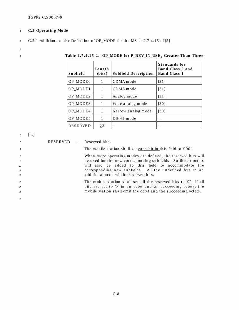
3GPP2 C.S0007-0
C-8
C.5 Operating Mode 1
C.5.1 Additions to the Definition of OP_MODE for the MS in 2.7.4.15 of [5] 2
3
Table 2.7.4.15-2. OP_MODE for P_REV_IN_USEs Greater Than Three 4
Subfield
Length (bits)
Subfield Description
Standards for Band Class 0 and Band Class 1
OP_MODE0 1 CDMA mode [31]
OP_MODE1 1 CDMA mode [31]
OP_MODE2 1 Analog mode [31]
OP_MODE3 1 Wide analog mode [30]
OP_MODE4 1 Narrow analog mode [30]
OP_MODE5 1 DS-41 mode –
RESERVED 23 – –
[…] 5
RESERVED – Reserved bits. 6
The mobile station shall set each bit in this field to ‘000’. 7
When more operating modes are defined, the reserved bits will 8
be used for the new corresponding subfields. Sufficient octets 9
will also be added to this field to accommodate the 10
corresponding new subfields. All the undefined bits in an 11
additional octet will be reserved bits. 12
The mobile station shall set all the reserved bits to ‘0’. If all 13
bits are set to ‘0’ in an octet and all succeeding octets, the 14
mobile station shall omit the octet and the succeeding octets. 15
16

3GPP2 C.S0007-0
C-9
C.5.2 Additions to the Definition of Operating Mode for the BS in 3.7.2.3.2.15 of [5] 1
2
Table 3.7.2.3.2.15-4. Operating Mode for MOB_P_REV Greater Than Three 3
Description
Standards for Band Class 0 and
Band Class 1
Value (binary)
CDMA mode [31] 00000000 or 00000001
Analog mode [31] 00000010
Wide analog mode [30] 00000011
Narrow analog mode
[30] 00000100
DS-41 mode – 00000101
All other values are reserved.
4
C.6 Data Burst Messages 5
C.6.1 Procedures 6
The base station may append a 4-bit RESPONSE_TAG at the end of a Data Burst Message. If 7
the mobile station receives a non-broadcast Data Burst Message containing a 8
RESPONSE_TAG field, the mobile station shall reply with a Data Burst Response Message. 9
The mobile station shall not send a Data Burst Response Message unless requested by the 10
base station (via the RESPONSE_TAG field included in a received Data Burst Message). 11
C.6.2 Message Definition 12
The Upper Layers PDU for the Data Burst Response Message has the following format: 13
MSG_TAG: DBRM 14
15
Field Length (bits)
RESPONSE_TAG 4
16
RESPONSE_TAG – Response tag. 17
The mobile station shall set this field to the value of the 18
RESPONSE_TAG field in the received Data Burst Message 19
which is being acknowledged by this message. 20
21

3GPP2 C.S0007-0
C-10
The mobile station shall use a MSG_ID value of ‘001111’ when the message is sent on the 1
r-csch and a MSG_TYPE value of ‘00100000’ when the message is sent on the r-dsch. 2
C.7 Additional DS_BLOB field in the Sync Channel Message of [5] 3
The Sync Channel Message is modified as follows: 4
5
Field Length (bits)
P_REV 8
MIN_P_REV 8
[…]
SR3_PILOT_POWER2 0 or 3
DS_INCL 1
DS_BLOB 0 or 24
6
SR3_PILOT_POWER2 – Relative power level between the primary SR3 pilot and the 7
pilot on the higher frequency of the two remaining SR3 8
frequencies. 9
If SR3_INCL is set to ‘0’, the base station shall omit this field; 10
otherwise, the base station shall set this field to the value 11
shown in Table 3.7.2.3.2.26-6 corresponding to the power 12
level of the primary pilot with respect to the pilot on the 13
higher frequency of the two remaining SR3 frequencies. 14
DS_INCL – Direct Spread (DS) System and Information Available. 15
If the base station includes the DS_BLOB field (containing 16
information on how to access a DS system), the base station 17
shall set this field to ‘1’; otherwise, the base station shall set 18
this field to ‘0’. 19
DS_BLOB – Access Information about a Direct Spread (DS) System. 20
If DS_INCL is set to ‘1’, the base station shall include this field 21
and set it as described below. 22
If DS_INCL is set to ‘0’, the base station shall omit this field. 23
24

3GPP2 C.S0007-0
C-11
The base station shall use the following format for the DS_BLOB field in the Sync Channel 1
Message: 2
3
Field Length (bits)
DS_SYNC 1
DS_BAND_CLASS 5
DS_FREQ 11
RESERVED 7
4
DS_SYNC - Synchronization indicator. 5
The base station shall set this field to ‘1’ if the DS system is 6
synchronized with the system that sends the Sync Channel 7
Message; otherwise, the base station shall set this field to ‘0’. 8
DS_BAND_CLASS - Band class where the DS system is deployed. 9
The base station shall set this field as described in [17]. 10
DS_FREQ - Channel number where the DS system is deployed. 11
The base station shall set this field to the channel number 12
where the DS system is deployed, using the numbering 13
scheme associated with DS_BAND_CLASS (see [2]). 14
RESERVED - Reserved bits. 15
The base station shall set this field to ‘0000000’. 16
17

3GPP2 C.S0007-0
C-12
No text. 1