JP-3GA-32.102(R99) 3G Telecom Management … JP-3GA-32.102(R99) JP-3GA-32.102(R99) 3G Telecom...
47
JP-3GA-32.102(R99) 3G Telecom Management Architecture Version 2 Nov 30, 2000 THE TELECOMMUNICATION TECHNOLOGY COMMITTEE
Transcript of JP-3GA-32.102(R99) 3G Telecom Management … JP-3GA-32.102(R99) JP-3GA-32.102(R99) 3G Telecom...
JP-3GA-32.102(R99)
3G Telecom Management Architecture
Version 2
Nov 30, 2000
THE TELECOMMUNICATION TECHNOLOGY COMMITTEE
JP-3GA-32.102(R99)i
JP-3GA-32.102(R99)3G Telecom Management architecture
Remarks
1.Application level of English descriptionApplication level:E3
English description is included in the text and figures of main body, annexes and appendices.
2.Relationship with international recommendations and standardsThis standard is standardized based on the Technical Specification 32.102 (Version 3.2.0) approved by 3GPP in
June 2000.
3.Departures from international recommendations3.1 Selection of optional items
None
3.2 Items of national matter
None
3.3 Changes to original standard
(1) Standards referred to in the original standard, which are replaced by TTC/ARIB standards.
Refer to Table 1.
(2) Items added to the original standard
None
(3) Items deleted from the original standard
None
(4) Items changed from the original standard
None
3.4 Difference in chapter ordering from the original standard.
There is no difference in chapter ordering from the original standard.
4.Change history
Revision Date Contents
V.1 Mar.31,2000 Newly standardized
V.2 Nov.30,2000 Revised based on the Technical Specification 32.102
(Version3.2.0) approved by 3GPP
5.IPRThere is no specific description about IPR in this standard.
6.OthersNone
JP-3GA-32.102(R99)ii
Table 1 Replaced standards referred
original standard replacement
3G TS 32.101
Title: 3G Telecom Management Principles and high
level requirements
TTC STANDARDS JP-3GA-32.101(R99)
Title: 3G Telecom Management Principles and high level
requirements
3G TS 32.102 V3.2.0 (2000-07)Technical Specification
3rd Generation Partnership Project;Technical Specification Group Services and System Aspects;
3G Telecom Management architecture(Release 1999)
The present document has been developed within the 3rd Generation Partnership Project (3GPP TM) and may be further elaborated for the purposes of 3GPP.The present document has not been subject to any approval process by the 3GPP Organisational Partners and shall not be implemented.This Specification is provided for future development work within 3GPP only. The Organisational Partners accept no liability for any use of this Specification.Specifications and reports for implementation of the 3GPP TM system should be obtained via the 3GPP Organisational Partners' Publications Offices.
3GPP
3G TS 32.102 V3.2.0 (2000-07)2Release 1999
KeywordsUMTS, TMN, management
3GPP
Postal address
3GPP support office address650 Route des Lucioles - Sophia Antipolis
Valbonne - FRANCETel.: +33 4 92 94 42 00 Fax: +33 4 93 65 47 16
Internethttp://www.3gpp.org
Copyright Notification
No part may be reproduced except as authorized by written permission.The copyright and the foregoing restriction extend to reproduction in all media.
© 2000, 3GPP Organizational Partners (ARIB, CWTS, ETSI, T1, TTA, TTC).All rights reserved.
3GPP
3G TS 32.102 V3.2.0 (2000-07)3Release 1999
ContentsForeword ......................................................................................................................................................5
1 Scope..................................................................................................................................................6
2 References...........................................................................................................................................62.1 Normative references ...................................................................................................................................62.2 Informative references .................................................................................................................................6
3 Definitions, symbols and abbreviations ................................................................................................73.1 Definitions...................................................................................................................................................73.2 Abbreviations...............................................................................................................................................9
4 General .............................................................................................................................................114.1 UMTS........................................................................................................................................................114.1.1 UMTS Reference Model .......................................................................................................................114.1.2 UMTS Provisioning Entities.................................................................................................................114.1.3 UMTS Management Infrastructure .......................................................................................................114.2 TMN..........................................................................................................................................................12
5 General view of UMTS Management Physical architectures...............................................................12
6 Basic objectives for a UMTS Physical Architecture ...........................................................................13
7 TM Architectural aspects ..................................................................................................................147.1 Architectural relationship ..........................................................................................................................147.2 Architectural constraints............................................................................................................................147.3 Interoperability ..........................................................................................................................................157.3.1 Interfaces..............................................................................................................................................157.3.2 Open systems approach ........................................................................................................................187.3.3 Level of openness .................................................................................................................................187.3.4 Closed interfaces ..................................................................................................................................197.4 Data communication networks ...................................................................................................................197.5 New technologies.......................................................................................................................................20
8 UMTS Management Physical architectures........................................................................................218.1 Compliance Conditions..............................................................................................................................218.2 Network elements management architecture ..............................................................................................218.3 Network & Subnetwork Element Management Architecture.......................................................................238.4 Operations Systems interoperability architecture. .......................................................................................248.5 Operations Systems intra-operability architecture.......................................................................................258.6 Business System interconnection architecture ............................................................................................25
9 TMN applications .............................................................................................................................27
10 Integration Reference Points (IRPs) ...................................................................................................2910.1 General......................................................................................................................................................2910.2 Integration levels .......................................................................................................................................2910.2.1 Application integration.........................................................................................................................2910.3 Network infrastructure IRPs.......................................................................................................................3010.4 Defining the IRPs ......................................................................................................................................3110.5 Mandatory, Optional and Conditional qualifiers.........................................................................................32
11 Implementation aspects......................................................................................................................3311.1 Layering of the OS applications .................................................................................................................33
12 TMN planning and design considerations...........................................................................................3412.1 Function attributes .....................................................................................................................................3412.2 Functional characteristics...........................................................................................................................3512.3 Critical attributes .......................................................................................................................................35
3GPP
3G TS 32.102 V3.2.0 (2000-07)4Release 1999
12.4 Protocol selection.......................................................................................................................................3512.5 Communications considerations.................................................................................................................36
13 Mediation/Integration ........................................................................................................................37
Annex A (informative): Technology considerations..........................................................................39
A.1 TMN physical blocks ........................................................................................................................39A.1.1 Operations System (OS).............................................................................................................................39A.1.2 Transformation ..........................................................................................................................................39A.1.2.1 Adaptation device.................................................................................................................................39A.1.2.2 Mediation Device (MD)........................................................................................................................39A.1.3 Network Element (NE) ..............................................................................................................................40A.1.4 Workstation (WS)......................................................................................................................................40A.1.5 Data Communication Network (DCN) .......................................................................................................40A.1.6 TMN logical layered architecture within the TMN physical architecture ....................................................41A.1.7 Interoperable interface concept...................................................................................................................41
A.2 TMN standard interfaces ...................................................................................................................42A.2.1 Q interface.................................................................................................................................................42A.2.2 F interface..................................................................................................................................................43A.2.3 X interface.................................................................................................................................................43A.2.4 Relationship of TMN interfaces to TMN physical blocks............................................................................43
Annex B (informative): Change history............................................................................................44
3GPP
3G TS 32.102 V3.2.0 (2000-07)5Release 1999
ForewordThis Technical Specification (TS) has been produced by the 3rd Generation Partnership Project (3GPP).
The contents of the present document are subject to continuing work within the TSG and may change followingformal TSG approval. Should the TSG modify the contents of the present document, it will be re-released by the TSGwith an identifying change of release date and an increase in version number as follows:
Version x.y.z
where:
x the first digit:
1 presented to TSG for information;
2 presented to TSG for approval;
3 or greater indicates TSG approved document under change control.
y the second digit is incremented for all changes of substance, i.e. technical enhancements, corrections,updates, etc.
z the third digit is incremented when editorial only changes have been incorporated in the document.
3GPP
3G TS 32.102 V3.2.0 (2000-07)6Release 1999
1 ScopeThe present document identifies identify and standardises the most important and strategic contexts in the physicalarchitecture for the management of UMTS. It serves as a framework to help define a telecom management physicalarchitecture for a planned UMTS and to adopt standards and provide products that are easy to integrate.
The present document is applicable to all further Technical Specifications regarding the Telecom Management ofUMTS.
2 ReferencesThe following documents contain provisions, which, through reference in this text, constitute provisions of the presentdocument.
• References are either specific (identified by date of publication, edition number, version number, etc.) ornon-specific.
• For a specific reference, subsequent revisions do not apply.
For a non-specific reference, the latest version applies.
2.1 Normative references [1] ITU-T Recommendation M.3010 (2000): "Principles for a telecommunications management
network".
[2] 3G TS 32.101: "3G Telecom Management principles and high level requirements".
[3] ITU-T Recommendation X.721: "Information technology - Open Systems Interconnection -Structure of management information: Definition of management information".
[4] ITU-T Recommendation X.200 (1994): "Information technology – Open Systems Interconnection– Basic reference model: The basic model".
[5] ITU-T Recommendation X.733: "Information technology - Open Systems Interconnection -Systems Management: Alarm reporting function".
[6] ITU-T Recommendation X.736: “Information technology – Open Systems Interconnection –Security Alarm Reporting Function”.
[7] ITU-T Recommendation M.3100-1995: “Generic network information model”.
[8] GSM 12.11: Digital cellular telecommunications system (Phase 2); Fault management of theBase Station System (BSS).
2.2 Informative references [20] TMF GB910. Smart TMN Telecom Operations Map (Release 1.1).
[21] TMF GB909. Smart TMN Technology Integration Map (Issue 1.1).
[22] ITU-T Recommendation M.3013 (2000): “Considerations for a telecommunications managementnetwork”.
3GPP
3G TS 32.102 V3.2.0 (2000-07)7Release 1999
3 Definitions, symbols and abbreviations
3.1 Definitions For the purposes of the present document, the following definitions apply:
Architecture: The organisational structure of a system or component, their relationships, and the principles andguidelines governing their design and evolution over time.
Closed interfaces: Privately controlled system/subsystem boundary descriptions that are not disclosed to the public orare unique to a single supplier.
De facto standard: A standard that is widely accepted and used but that lacks formal approval by a recognisedstandards organisation.
Interface standard: A standard that specifies the physical or functional interface characteristics of systems,subsystems, equipment, assemblies, components, items or parts to permit interchangeability, interconnection,interoperability, compatibility, or communications.
Interoperability: The ability of two or more systems or components to exchange data and use information.
Intra-operability: The ability to interchange and use information, functions and services among components within asystem.
IRPAgent: The IRPAgent encapsulates a well-defined subset of network (element) functions. It interacts withIRPManagers using an IRP. From the IRPManager’s perspective, the IRPAgent behaviour is only visible via the IRP.
IRPManager: The IRPManager models a user of the IRPAgent and it interacts directly with the IRPAgent using theIRP. Since the IRPManager represents an IRPAgent user, they help delimit the IRPAgent and give a clear picture ofwhat the IRPAgent is supposed to do. From the IRPAgent perspective, the IRPManager behaviour is only visible viathe IRP.
IRP Information Model: An IRP Information Model consists of an IRP Information Service and a Network ResourceModel (see below for definitions of IRP Information Service and Network Resource Model).
IRP Information Service: An IRP Information Service describes the information flow and support objects for acertain functional area, e.g. the alarm information service in the fault management area. As an example of supportobjects, for the Alarm IRP there is the "alarm information" and "alarm list".
IRP Solution Set: An IRP Solution Set is a mapping of the IRP Information Service to one of several technologies(CORBA/IDL, SNMP/SMI, CMIP/GDMO etc.). An IRP Information Service can be mapped to several different IRPSolution Sets. Different technology selections may be done for different IRPs.
Management Infrastructure: The collection of systems (computers and telecommunications) a UMTS Organisationhas in order to manage UMTS.
Market Acceptance: Market acceptance means that an item has been accepted in the market as evidenced by annualsales, length of time available for sale, and after-sale support capability.
Modular: Pertaining to the design concept in which interchangeable units are employed to create a functional endproduct.
Module: An interchangeable item that contains components. In computer programming, a program unit that isdiscrete and identifiable with respect to compiling, combining with other modules, and loading is called a module.
Network Resource Model (NRM): A protocol independent model describing managed objects representing networkresources, e.g. an RNC or NodeB.
Open Specifications: Public specifications that are maintained by an open, public consensus process to accommodatenew technologies over time and that are consistent with international standards.
3GPP
3G TS 32.102 V3.2.0 (2000-07)8Release 1999
Open Standards: Widely accepted and supported standards set by recognised standards organisation or thecommercial market place. These standards support interoperability, portability, and scalability and are equallyavailable to the general public at no cost or with a moderate license fee.
Open Systems Architecture (OSA): An architecture produced by an open systems approach and employing opensystems specifications and standards to an appropriate level.
Open Systems Strategy: An open systems strategy focuses on fielding superior telecom capability more quickly andmore affordably by using multiple suppliers and commercially supported practices, products, specifications, andstandards, which are selected based on performance, cost, industry acceptance, long term availability andsupportability, and upgrade potential.
Physical Architecture: A minimal set of rules governing the arrangement, interaction, and interdependence of theparts or elements whose purpose is to ensure that a conformant system satisfies a specified set of requirements. Thephysical architecture identifies the services, interfaces, standards, and their relationships. It provides the technicalguidelines for implementation of systems upon which engineering specifications are based and common buildingblocks are built.
Plug&play: Term for easy integration of HW/SW.
Portability: The ease with which a system, component, data, or user can be transferred from one hardware or softwareenvironment to another.
Proprietary Specifications: Specifications, which are exclusively owned by a private individual or corporation undera trademark or patent, the use of which would require a license.
Reference Model: A generally accepted abstract representation that allows users to focus on establishing definitions,building common understandings and identifying issues for resolution. For TMN Systems acquisitions, a referencemodel is necessary to establish a context for understanding how the disparate technologies and standards required toimplement TMN relate to each other. A reference model provides a mechanism for identifying the key issuesassociated with applications portability, modularity, scalability and interoperability. Most importantly, ReferenceModels will aid in the evaluation and analysis of domain-specific architectures.
Scalability: The capability to adapt hardware or software to accommodate changing workloads.
Specification: A document that prescribes, in a complete, precise, verifiable manner, the requirements, design,behaviour, or characteristics of a system or system component.
Standard: A document that establishes uniform engineering and technical requirements for processes, procedures,practices, and methods. Standards may also establish requirements for selection, application, and design criteria ofmaterial.
Standards Based Architecture: An architecture based on an acceptable set of open standards governing thearrangement, interaction, and interdependence of the parts or elements that together may be used to form a TMNSystem, and whose purpose is to insure that a conformant system satisfies a specified set of requirements.
System : Any organised assembly of resources and procedures united and regulated by interaction or interdependenceto accomplish a set of specific functions.
System Architecture: A description, including graphics, of systems and interconnections providing for or supportingmanagement functions. The SA defines the physical connection, location, and identification of the key nodes, circuits,networks, platforms, etc., and specifies system and component performance parameters. It is constructed to satisfyOperational Architecture requirements per standards defined in the Physical Architecture. The SA shows howmultiple systems within a subject area link and inter-operate, and may describe the internal construction or operationsof particular systems within the architecture.
UMTS Organisation: A legal entity that is involved in the provisioning of UMTS.
3GPP
3G TS 32.102 V3.2.0 (2000-07)9Release 1999
3.2 Abbreviations For the purposes of the present document, the following abbreviations apply:
3G 3rd GenerationATM Asynchronous Transfer ModeBG Border GatewayBSC Base Station ControllerBSS Base Station SubsystemBTS Base Transceiver StationCIM Common Information Model Specification (from DMTF)CMIP Common Management Information ProtocolCMIS Common Management Information ServiceCMISE Common Management Information Service ElementCORBA Common Object Request Broker ArchitectureDCN Data Communication NetworkDECT Digital Enhanced Cordless TelecommunicationsDSS1 Digital Subscriber System 1FM Fault ManagementFTAM File Transfer, Access and ManagementF/W FirewallGDMO Guidelines for the Definition of Managed ObjectsGGSN Gateway GPRS Support NodeGPRS General Packet Radio ServiceHLR Home Location RegisterHTTP HyperText Transfer ProtocolIDL Interface Definition LanguageIIOP Internet Inter-ORB ProtocolINAP Intelligent Network Application PartIP Internet ProtocolIRP Integration Reference PointISDN Integrated Services Digital NetworkIWU Inter Working Unit MD Mediation Device MIB Management Information Base MMI Man-Machine Interface MML Man-Machine Language MSC Mobile service Switching Centre NE Network Element NR Network Resource NRM Network Resource Model NSS Network Switching Subsystem NW Network OMG Object Management Group OS Operations System OSF Operations System Functions PDH Plesiochronous Digital Hierarchy PSA Product Specific Applications PSTN Public Switched Telephone Network QA Q-Adapter QoS Quality of Service RNC Radio Network ControllerRSVP Resource ReserVation Protocol SDH Synchronous Digital Hierarchy SGSN Serving GPRS Support Node SLA Service Level Agreement SMI Structure of Management Information SNMP Simple Network Management Protocol SS7 Signalling System No. 7
3GPP
3G TS 32.102 V3.2.0 (2000-07)10Release 1999
TM Telecom Management TMN Telecommunications Management Network as defined in ITU-T Recommendation M.3010 [1]. UML Unified Modelling Language UMTS Universal Mobile Telecommunications System UTRA Universal Terrestrial Radio Access UTRAN Universal Terrestrial Radio Access Network VHE Virtual Home Environment VLR Visitor Location Register WBEM Web Based Enterprise Management WS Workstation
3GPP
3G TS 32.102 V3.2.0 (2000-07)11Release 1999
4 General
4.1 UMTS
4.1.1 UMTS Reference Model A Universal Mobile Telecommunications System is made of the following components:
- one or more Access Networks, using different types of access techniques (GSM, UTRA, DECT, PSTN,ISDN,...) of which at least one is UTRA;
- one or more Core Networks;
- one or more Intelligent Node Networks, service logic and mobility management, (IN, GSM...);
- one or more transmission networks (PDH, SDH etc) in various topologies (point-to-point, ring, point-to-multipoint etc) and physical means (radio, fibre, copper etc).
The UMTS components have signalling mechanisms among them (DSS1, INAP, MAP, SS7, RSVP etc.).
From the service perspective, the UMTS is defined to offer:
- service support transparent to the location, access technique and core network, within the bearer capabilitiesavailable in one particular case;
- user to terminal and user to network interface (MMI) irrespective of the entities supporting the servicesrequired (VHE);
- multimedia capabilities.
4.1.2 UMTS Provisioning Entities Two major entities, which cover the set of UMTS functionalities involved in the provision of the UMTS services to theuser, are identified as follows:
Home Environment. This entity holds the functionalities that enable a user to obtain UMTS services in a consistentmanner regardless of the user's location or the terminal used.
Serving Network. This entity provides the user with access to the services of the Home Environment.
4.1.3 UMTS Management Infrastructure Every UMTS Organisation has it's own Management Infrastructure. Each Management Infrastructure will containdifferent functionality depending on the role-played and the equipment used by that UMTS Entity.
However, the core management architecture of the UMTS Organisation is very similar. Every UMTS Organisation:
- provides services to it's customers;
- needs an infrastructure to fulfil them (advertise, ordering, creation, provisioning,...);
- assures them (Operation, Quality of Service, Trouble Reporting and Fixing,...);
- bills them (Rating, Discounting,...).
Not every UMTS Organisation will implement the complete Management Architecture and related Processes. Someprocesses may be missing dependent on the role a particular UMTS Organisation is embodying. Processes notimplemented by a particular UMTS Organisation are accessed via interconnections to other UMTS organisations,which have implemented these processes (called X-interfaces in the TMN architecture).
3GPP
3G TS 32.102 V3.2.0 (2000-07)12Release 1999
The Management architecture itself does not distinguish between external and internal interfaces.
4.2 TMN TMN (Telecommunications Management Network), as defined in [1], provides:
- an architecture, made of OS (Operations Systems) and NEs (Network Elements), and the interfaces betweenthem (Q, within one Operator Domain and X, between different Operators);
- the methodology to define those interfaces;
- other architectural tools such as LLA (Logical Layered Architecture) that help to further refine and define theManagement Architecture of a given management area;
- a number of generic and/or common management functions to be specialised/applied to various and specificTMN interfaces.
The UMTS Management Architecture is largely based on TMN, and will reuse those functions, methods andinterfaces already defined (or being defined) that are suitable to the management needs of UMTS. However, the UMTSManagement needs to explore the incorporation of other concepts (other management paradigms widely accepted anddeployed) since:
- UMTS incorporates other technologies to which TMN is not applied fully;
- UMTS faces new challenges that TMN does not address today.
It shall be noted, that these concerns are applicable to other telecommunication areas as well as to UMTS, it isexpected that the eventual evolution of TMN will cover this ground. Indeed, most of the above concepts are alreadybeing taken into account by TMN evolution (protocols and methodologies).
5 General view of UMTS Management Physicalarchitectures
Telecom Management Architectures can vary greatly in scope and detail. The architecture for a large service provider,with a lot of existing legacy systems and applications, upon which many services are based, will be of high complexity.In contrast, the architectural needs of a start-up mobile operator providing its services to a small group of value addedService Providers will be much less and will probably focus on more short-term needs.
A mobile network operator has to manage many different types of networks as radio networks, exchanges,transmission networks, area networks, intelligent nodes and substantial amounts of computer hardware/software. Thiswide variety of network equipment shall be obtained from a variety of equipment vendors. The nature of a mobileradio network will be heterogeneous and will present a number of operational difficulties for the service provider onenabling effective and efficient network management.
The standardisation work for the management of UMTS has adopted the top-down approach and will from businessneeds identify functional and informational architectures. The physical architecture will have to meet theserequirements and as there are many ways to build a UMTS it will vary greatly from one TMN solution to another.There will be many physical implementations, as different entities will take different roles in a UMTS.
It is obvious that it will not be meaningful or even possible to fully standardise a common telecom managementphysical architecture for UMTS. This document will identify and standardise the most important and strategiccontexts and serve as a framework to help define a physical architecture for a planned UMTS.
3GPP
3G TS 32.102 V3.2.0 (2000-07)13Release 1999
6 Basic objectives for a UMTS Physical ArchitectureThe management of UMTS will put a lot of new requirements to the management systems compared to the secondgeneration of Mobile telephony. Some of the challenging requirements affecting the physical architecture are:
- To be capable of managing equipment supplied by different vendors.
- To enable TM automation in a more cost efficient way - TM optimised for maximum efficiency andeffectiveness.
- To provide UMTS configuration capabilities that are flexible enough to allow rapid deployment of services.
- To report events and reactions in a common way in order to allow remote control.
- To allow interoperability between Network Operators/Service Providers for the exchange ofmanagement/charging information.
- To be scaleable and applicable to both larger and small deployments.
- Accessibility to information.
- To profit from advances and standards in IT and datacom industry.
The second generation of mobile networks can - from management point of view - be characterised as the era ofnet-element vendor-dependent NE managers. The different OSs had very low interoperability with other systems andfunctional blocks could rarely be re-used. The Mobile Telecom Management Networks were far away from the TMNvision where one vendor’s OS should be able to manage other vendor’s net elements.
For UMTS Management it is clearly stated the necessity of cost-effective solutions and better time to market focus.Interoperability, scalability and re-use are keywords for the new generation of management systems.
Many of the new requirements on the management of UMTS can only be solved by defining and establish a suitablephysical architecture. Thou it is not possible to standardise the one single UMTS TM physical architecture, it isevidently so that the success of a telecom management network of a UMTS will heavily depend on critical physicalarchitectural issues. This document will identify those architectural critical issues.
3GPP
3G TS 32.102 V3.2.0 (2000-07)14Release 1999
7 TM Architectural aspects
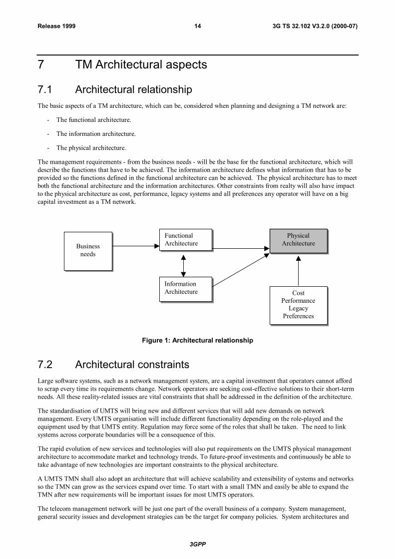
7.1 Architectural relationshipThe basic aspects of a TM architecture, which can be, considered when planning and designing a TM network are:
- The functional architecture.
- The information architecture.
- The physical architecture.
The management requirements - from the business needs - will be the base for the functional architecture, which willdescribe the functions that have to be achieved. The information architecture defines what information that has to beprovided so the functions defined in the functional architecture can be achieved. The physical architecture has to meetboth the functional architecture and the information architectures. Other constraints from realty will also have impactto the physical architecture as cost, performance, legacy systems and all preferences any operator will have on a bigcapital investment as a TM network.
Businessneeds
FunctionalArchitecture
InformationArchitecture
PhysicalArchitecture
CostPerformance
LegacyPreferences
Figure 1: Architectural relationship
7.2 Architectural constraintsLarge software systems, such as a network management system, are a capital investment that operators cannot affordto scrap every time its requirements change. Network operators are seeking cost-effective solutions to their short-termneeds. All these reality-related issues are vital constraints that shall be addressed in the definition of the architecture.
The standardisation of UMTS will bring new and different services that will add new demands on networkmanagement. Every UMTS organisation will include different functionality depending on the role-played and theequipment used by that UMTS entity. Regulation may force some of the roles that shall be taken. The need to linksystems across corporate boundaries will be a consequence of this.
The rapid evolution of new services and technologies will also put requirements on the UMTS physical managementarchitecture to accommodate market and technology trends. To future-proof investments and continuously be able totake advantage of new technologies are important constraints to the physical architecture.
A UMTS TMN shall also adopt an architecture that will achieve scalability and extensibility of systems and networksso the TMN can grow as the services expand over time. To start with a small TMN and easily be able to expand theTMN after new requirements will be important issues for most UMTS operators.
The telecom management network will be just one part of the overall business of a company. System management,general security issues and development strategies can be the target for company policies. System architectures and
3GPP
3G TS 32.102 V3.2.0 (2000-07)15Release 1999
technology choices, as well as the availability of off-the-shelf commercial systems and software components that fulfilthe requirements established in this specification, may be critical to an operator’s implementation of the specifiedUMTS management architecture.
7.3 InteroperabilityThe new requirement on a UMTS TMN will imply a focus change from net element management towardsmanagement of information "information management". Network providers make use of different information inseveral different ways which also may vary from network to network and from time to time. Basic information asalarms is of course essential information for localising faults but may also be the key information to be able to set up aservice with a service level agreement.
Numerous of different interfaces can be identified in a UMTS network in the areas of network element management,network management and service management. The most important and complex of these interfaces will bestandardised but many interfaces of less importance are unlikely to be fully standardised and will be up to theindividual operator and vendor to develop. To adopt mainstream computing technologies, re-use widely usedprotocols, standards and an open system architecture will be essential to secure interworking between all physicalentities in a UMTS.
Low-cost and general access to management systems information will be needed. Obviously this is the critical issueand challenging task in the heterogeneous, distributed and complex network of a UMTS.
7.3.1 InterfacesA UMTS will consist of many different types of components based on different types of technologies. There will beaccess-, core-, transmission- and intelligent node networks and many of the UMTS components have already been thetargets for Telecom Management standardisation at different levels. Many of these standards will be reused and themanagement domain of a UMTS will thereby consist of many TMNs. An architectural requirement for UMTSmanagement shall be to support distributed TMNs and TMN-interworking on peer-to-peer basis.
The Telecom Management Architecture can vary greatly in scope and detail, because of scale of operation and thatdifferent organisations may take different roles in a UMTS (see clause 5). The architecture of UMTS TMNs shallprovide a high degree of flexibility to meet the various topological conditions as the physical distribution and thenumber of NEs. Flexibility is also required to allow high degree of centralisation of personnel and the administrativepractices as well as allowing dispersion to administrative domains (see further clause 10). The 3G TelecomManagement architecture shall be such that the NEs will operate in the same way, independently of the OSarchitecture.
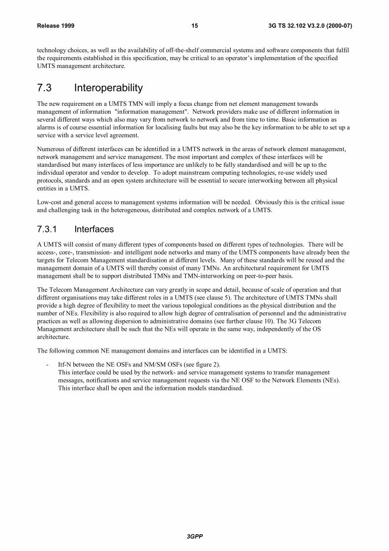
The following common NE management domains and interfaces can be identified in a UMTS:
- Itf-N between the NE OSFs and NM/SM OSFs (see figure 2).This interface could be used by the network- and service management systems to transfer managementmessages, notifications and service management requests via the NE OSF to the Network Elements (NEs).This interface shall be open and the information models standardised.
3GPP
3G TS 32.102 V3.2.0 (2000-07)16Release 1999
OSFGSM NSS
OSFUTRAN
OSFGPRS NEs
OSFGSM BSS
OSFTerminal
OSF for Network Management andService Management
Itf-N
NEManagement
Figure 2: Overview of UMTS Telecom Management Domains and Itf-N
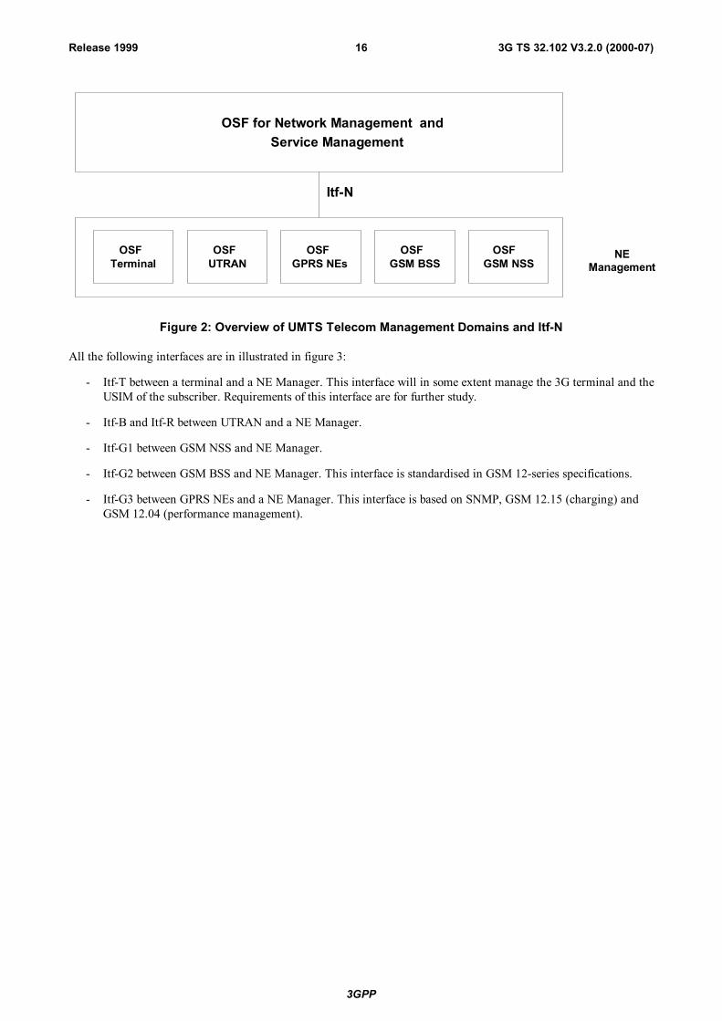
All the following interfaces are in illustrated in figure 3:
- Itf-T between a terminal and a NE Manager. This interface will in some extent manage the 3G terminal and theUSIM of the subscriber. Requirements of this interface are for further study.
- Itf-B and Itf-R between UTRAN and a NE Manager.
- Itf-G1 between GSM NSS and NE Manager.
- Itf-G2 between GSM BSS and NE Manager. This interface is standardised in GSM 12-series specifications.
- Itf-G3 between GPRS NEs and a NE Manager. This interface is based on SNMP, GSM 12.15 (charging) andGSM 12.04 (performance management).
3GPP
3G TS 32.102 V3.2.0 (2000-07)17Release 1999
OSFGSM BSS
OSFUTRAN
Itf-B andItf-R
OSFTerminal
Itf-T
OSFGPRS NE's
Itf-G3 SNMP/GSM12.15,12.04
Itf-G2Q3/GSM 12.xx
Iu
Terminal
BTSBSC
GSM BSS
Uu
UTRAN
RNCNodeB
Iub
SGSN
GGSN GGSN
GPRS Network
OtherGPRSoperator
BG
F/W
F/W
GPRSBackbone
Data network(Internet)
Data network(X.25)
Data network(Intranet)
IWU
Terminal
PSTN
MSC/VLR
HLR
OSFGSM NSS
Itf-G1 Q3
F/W
GSM NSS
Figure 3: Overview of a UMTS Network, showing management interfaces and management domains
- Itf-T between a terminal and a NE Manager. This interface will in some extent manage the 3G terminal and theUSIM of the subscriber. Requirements of this interface are for further study.
- Itf-B and Itf-R between UTRAN and a NE Manager.
- Itf-G1 between GSM NSS and NE Manager.
- Itf-G2 between GSM BSS and NE Manager. This interface is standardised in GSM 12-series specifications.
- Itf-G3 between GPRS NEs and a NE Manager. This interface is based on SNMP, GSM 12.15 (charging) andGSM 12.04 (performance management).
Telecom management interfaces may be considered from two perspectives:
- the management information model;
- the management information exchange.
The management information models will be standardised in other 3GPP documents but the management informationexchange will be further described in this architectural standard.
The management task will vary greatly between different network elements in a UMTS. Some NEs are of highcomplexity e.g. a RNC, while others e.g. a border gateway is of less complexity. Different application protocols can bechosen to best suite the management requirements of the different Network Elements and the technology used.
3GPP
3G TS 32.102 V3.2.0 (2000-07)18Release 1999
Application protocols can be categorised out of many capabilities as:
- Functionality;
- Implementation complexity;
- Processor requirements;
- Cost efficiency;
- Market acceptance, availability of "off the shelf commercial systems and software".
For each telecom management interface that will be standardised by 3GPP at least one of the accepted protocols willbe recommended. Accepted application protocols (e.g. CMIP, SNMP, CORBA IIOP) are defined in [2], Annex A.
7.3.2 Open systems approachEven in the second generation of mobile radio networks the operators has to cope with heterogeneous environments inmany different ways. No single vendor is likely to deliver all the management systems needed for a mobile operator.
The many different types of network elements, some with very high management complexity as an exchange and someless complex as a repeater system, are generally supported with unique vendor specific management systems with verylow interoperability. Duplicated TMN applications is another obvious reality of this generation of managementsystems. This will be further discussed under Chapter 9 (TMN Applications).
The new UMTS requirements call for open systems that can be supported by the marketplace, rather than beingsupported by a single (or limited) set of suppliers, due to the unique aspects of the design chosen. Open systemsarchitectures are achieved by having the design focus on commonly used and widely supported interface standards.This should ensure costs and quality that are controlled by the forces of competition in the marketplace.
The open systems approach is a technical and business strategy to:
- Choose commercially supported specifications and standards for selected system interfaces.
- Build systems based on modular hardware and software design.
Selection of commercial specifications and standards in the Open systems approach should be based on:
- Those adopted by industry consensus based standards bodies or de facto standards (those successful in themarket place).
- Market research that evaluates the short and long term availability of products.
- Trade-offs of performance.
- Supportability and upgrade potential within defined cost constraint.
- Allowance for continued access to technological innovation supported by many customers and a broadindustrial base.
7.3.3 Level of opennessThe level the interfaces conform to open standards is critical for the overall behaviour. A low level of openness willseverely impact on long-term supportability, interoperability, development lead-time, and lifecycle cost and overallperformance.
Interfaces are expensive parts in a TMN and interfaces with low level of openness severely impact on developmentlead-time for the introduction of any system, application component or service. Easy implementation (plug & play) isa requirement for UMTS TMN physical entities and requires a high the level of openness.
3GPP
3G TS 32.102 V3.2.0 (2000-07)19Release 1999
7.3.4 Closed interfacesMany second-generation mobile network physical management entities have vendor controlled system/subsystemboundary descriptions that are not disclosed to the public or are unique to this single supplier - closed interfaces.
In a UMTS network, such interfaces will not fulfil the basic requirements and can not be a part of a UMTS TMN.
Closed interfaces can only be used as internal interfaces where no information what so ever has to be shared to otherphysical management entities.
7.4 Data communication networksWithin a TMN, the necessary physical connection (e.g. circuit-switched or packet-switched) may be offered bycommunication paths constructed with all kinds of network components, e.g. dedicated lines, packet-switched datanetwork, ISDN, common channel signalling network, public-switched telephone network, local area networks,terminal controllers, etc. In the extreme case the communication path provides for full connectivity, i.e. each attachedsystem can be physically connected to all others.
The TMN should be designed such that it has the capability to interface with several types of communications paths, toensure that a framework is provided which is flexible enough to allow the most efficient communications:
- between NE and other elements within the TMN;
- between WS and other elements within the TMN;
- between elements within the TMN;
- between TMNs;
- between TMNs and enterprise.
In this case the term efficiency relates to the cost, reliability and maintainability of the data transported.
Two aspects impact costs. The first is the actual cost to transport data across the network between the TMN and theNE. The second aspect is the design of the interface including the selection of the appropriate communicationsprotocol.
Whatever standardised protocol suite at the networking level that is capable of meeting the functional and operationalrequirements (including the network addressing aspects) of the Logical and Application Protocol levels of a givenUMTS management interface, is a valid Networking Protocol for that interface.
A number of requirements shall be met by the Networking Protocol, as follows:
- Capability to run over any bearer (leased lines, X.25, ATM, Frame Relay,...)
- Support of existing transport protocols and their applications, such as OSI, TCP/IP family, etc.
- Widely available, cheap and reliable.
The Internet Protocol (IP) is a Networking Protocol that ideally supports these requirements. IP also adds flexibility tohow management connectivity is achieved when networks are rolled out, by offering various implementation choices.For instance, these may take the form of:
- Dedicated management intranets.
- Separation from or integration into an operator’s enterprise network.
- Utilisation, in one way or another, of capacities of the public Internet and its applications or other resources.
3GPP
3G TS 32.102 V3.2.0 (2000-07)20Release 1999
7.5 New technologiesMeeting application requirements in the most affordable manner is together with development lead-time importantissues identified in early UMTS management standardisation work. But the TMN functional, information and physicalarchitectures shall also keep pace with the introduction of new technologies, services and evolving networkinfrastructures. Technology is advancing so rapidly today that this shall be a fundamental part of the physicalarchitecture – to be able to easily adopt new important technologies.
A UMTS will need to incorporate new successful technologies from the IT-world to which TMN standardisation is notfully applicable. Today distributed computing implementations have matured to a point where the goals of TMN canbe realised using commonly available technologies for a reasonable cost.
Widely accepted open standards and new IT-technologies will be indispensable to fulfil the challenging managingrequirements of UMTS.
New technologies in the IT business as generic application components together with distributed processingtechnology are new important drivers upon application design of management systems. The possibility to purchasefunctional components from the open market are of great importance from many aspects as cost-efficiency and time-to-market.
3GPP
3G TS 32.102 V3.2.0 (2000-07)21Release 1999
8 UMTS Management Physical architecturesA UMTS Telecom Management Network will consist of many different management layers and many differentbuilding blocks. The complexity will vary greatly in detail because every organisation has different needs. Thefollowing clause will identify the most critical architectural issues and compliance conditions for a given UMTSManagement Interface. It should serve as fundamental requirements for any UMTS entity (network element ormanagement system) being a part of a UMTS TMN.
8.1 Compliance ConditionsFor a UMTS entity (Management System or NE) to be compliant to a given UMTS Management Interface, all thefollowing conditions shall be satisfied:
1) It implements the management functionality following the Information Model and flows specified by therelevant 3GPP UMTS Management Interface Specifications applicable to that interface.
2) It provides at least one of the IRP Solution Sets (were available) related to the valid Application Protocolsspecified by 3GPP UMTS Application Protocols for that interface, [2] Annex C.
3) It provides at least one standard networking protocol.
4) In case the entity does not offer the management interface on its own, a Q-Adapter shall be provided. ThisQ-Adapter shall be provided independently of any other UMTS NE and/or UMTS Management System.
5) Support for Bulk Transfer Application Protocols specified by the relevant 3GPP UMTS Management InterfaceSpecifications applicable to that interface.
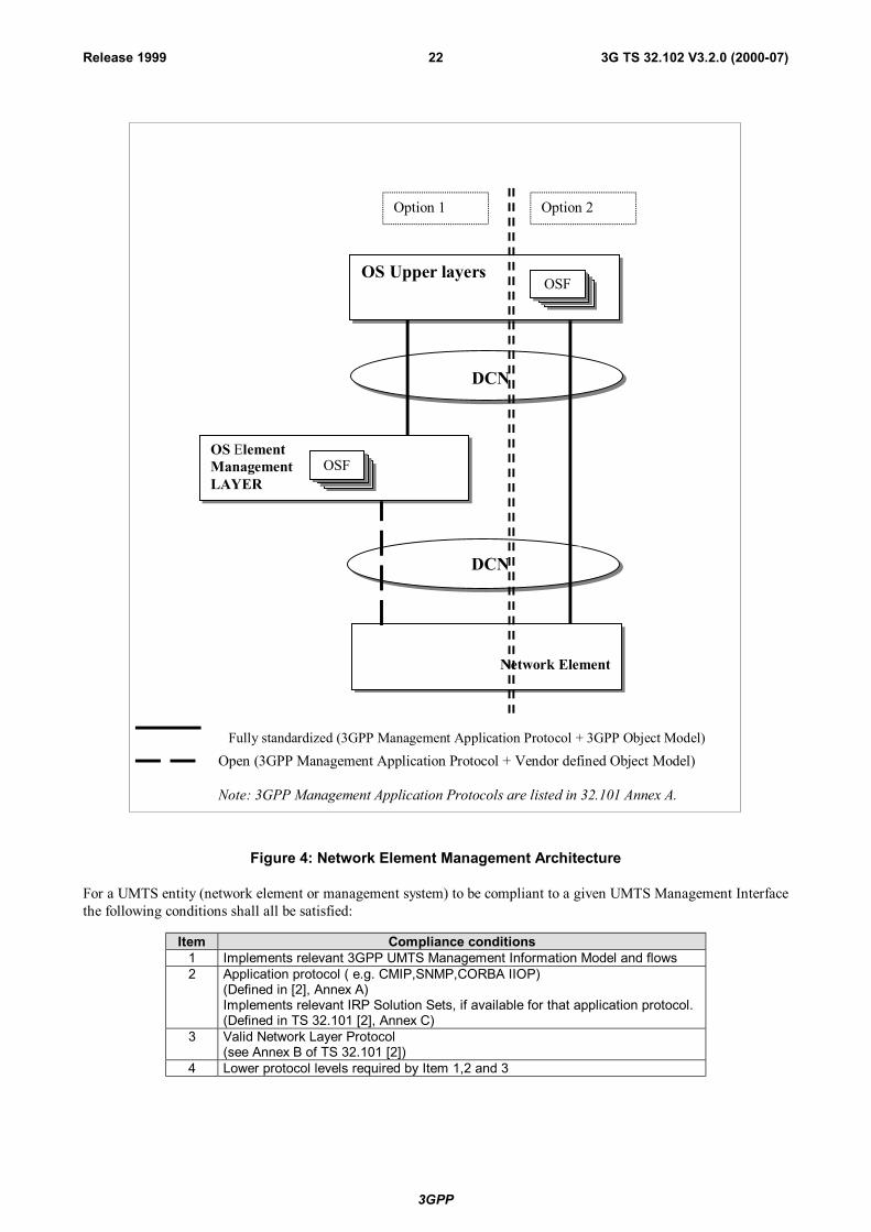
8.2 Network elements management architectureThe following figure demonstrates two possible options for management interface from the OS upper layers to NE.Option 1, provides access to the NE via element manager, and Option 2, provides a direct access. It is sufficient toprovide one or the other.
3GPP
3G TS 32.102 V3.2.0 (2000-07)22Release 1999
OS Upper layersOSF
OS ElementManagementLAYER
OSF
Network Element
Fully standardized (3GPP Management Application Protocol + 3GPP Object Model)
DCN
DCN
Open (3GPP Management Application Protocol + Vendor defined Object Model)
Note: 3GPP Management Application Protocols are listed in 32.101 Annex A.
Option 1 Option 2
Figure 4: Network Element Management Architecture
For a UMTS entity (network element or management system) to be compliant to a given UMTS Management Interfacethe following conditions shall all be satisfied:
Item Compliance conditions1 Implements relevant 3GPP UMTS Management Information Model and flows2 Application protocol ( e.g. CMIP,SNMP,CORBA IIOP)
(Defined in [2], Annex A)Implements relevant IRP Solution Sets, if available for that application protocol.(Defined in TS 32.101 [2], Annex C)
3 Valid Network Layer Protocol(see Annex B of TS 32.101 [2])
4 Lower protocol levels required by Item 1,2 and 3
3GPP
3G TS 32.102 V3.2.0 (2000-07)23Release 1999
Any other entity taking part in a UMTS, as an implementation choice, shall satisfy the following condition:
Item Compliance conditions1 Not standardised but open
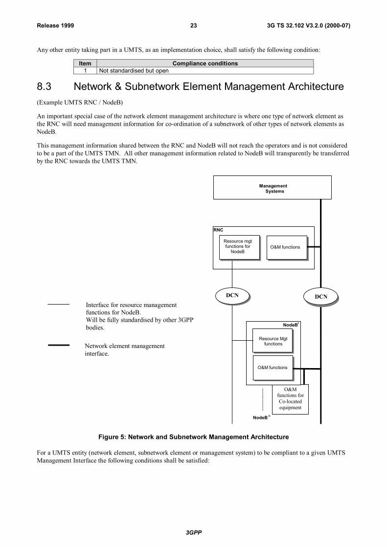
8.3 Network & Subnetwork Element Management Architecture(Example UMTS RNC / NodeB)
An important special case of the network element management architecture is where one type of network element asthe RNC will need management information for co-ordination of a subnetwork of other types of network elements asNodeB.
This management information shared between the RNC and NodeB will not reach the operators and is not consideredto be a part of the UMTS TMN. All other management information related to NodeB will transparently be transferredby the RNC towards the UMTS TMN.
DCN
ManagementSystems
O&M functions
O&Mfunctions forCo-locatedequipment
Resource Mgtfunctions
O&M functions
Resource mgtfunctions for
NodeB
RNC
NodeBI
NodeB n
Interface for resource managementfunctions for NodeB.Will be fully standardised by other 3GPPbodies.
Network element managementinterface.
DCN
Figure 5: Network and Subnetwork Management Architecture
For a UMTS entity (network element, subnetwork element or management system) to be compliant to a given UMTSManagement Interface the following conditions shall be satisfied:
3GPP
3G TS 32.102 V3.2.0 (2000-07)24Release 1999
Item Compliance conditions1 Implements relevant 3GPP UMTS Management Information Model and flows2 Application protocol ( e.g. CMIP,SNMP,CORBA IIOP)
(Defined in [2], Annex A)Implements relevant IRP Solution Sets, if available for that application protocol.(Defined in [2], Annex C)
3 Valid Network Layer Protocol(see Annex B of TS 32.101 [2])
4 Lower protocol levels required by Item 1,2 and 3
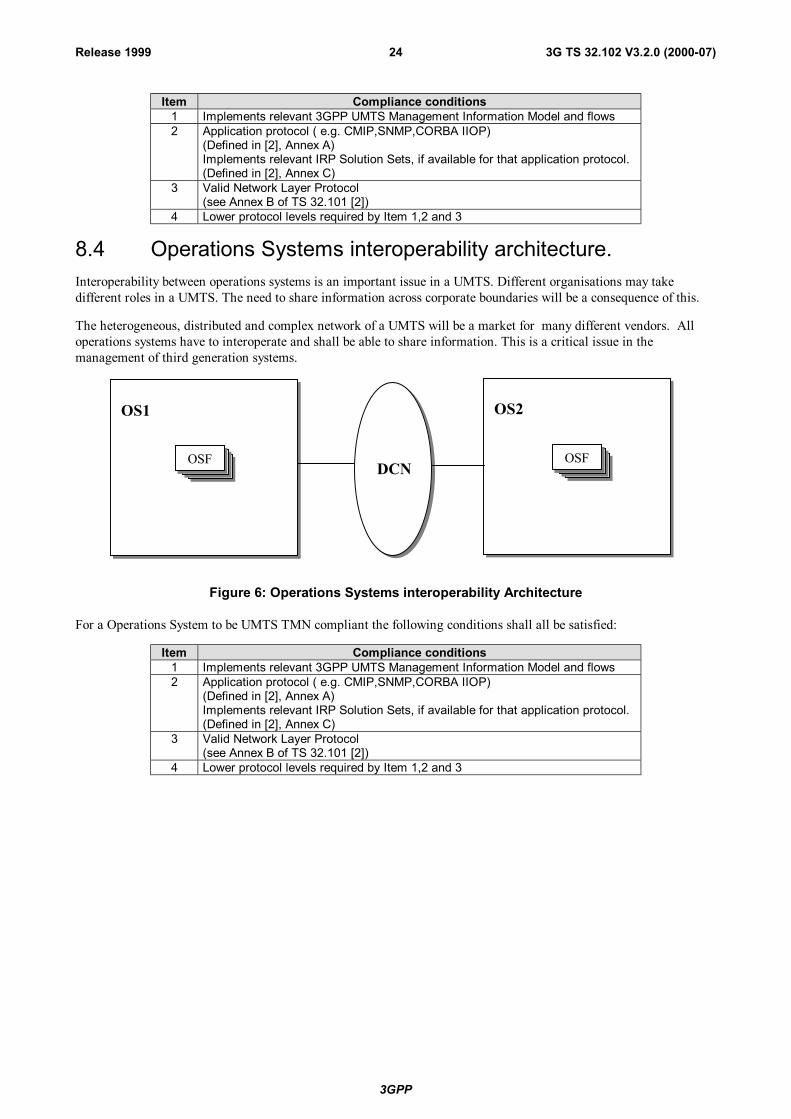
8.4 Operations Systems interoperability architecture.Interoperability between operations systems is an important issue in a UMTS. Different organisations may takedifferent roles in a UMTS. The need to share information across corporate boundaries will be a consequence of this.
The heterogeneous, distributed and complex network of a UMTS will be a market for many different vendors. Alloperations systems have to interoperate and shall be able to share information. This is a critical issue in themanagement of third generation systems.
OS1 OS2
OSFOSFDCN
Figure 6: Operations Systems interoperability Architecture
For a Operations System to be UMTS TMN compliant the following conditions shall all be satisfied:
Item Compliance conditions1 Implements relevant 3GPP UMTS Management Information Model and flows2 Application protocol ( e.g. CMIP,SNMP,CORBA IIOP)
(Defined in [2], Annex A)Implements relevant IRP Solution Sets, if available for that application protocol.(Defined in [2], Annex C)
3 Valid Network Layer Protocol(see Annex B of TS 32.101 [2])
4 Lower protocol levels required by Item 1,2 and 3
3GPP
3G TS 32.102 V3.2.0 (2000-07)25Release 1999
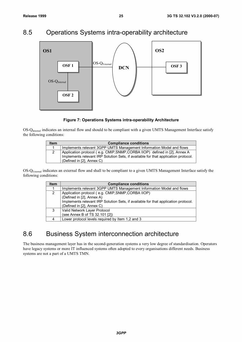
8.5 Operations Systems intra-operability architecture
OS-QExternal
OS1 OS2
OSF 1
OSF 2
OSF 3
OS-QInternal
DCN
Figure 7: Operations Systems intra-operability Architecture
OS-QInternal indicates an internal flow and should to be compliant with a given UMTS Management Interface satisfythe following conditions:
Item Compliance conditions1 Implements relevant 3GPP UMTS Management Information Model and flows2 Application protocol ( e.g. CMIP,SNMP,CORBA IIOP) defined in [2], Annex A
Implements relevant IRP Solution Sets, if available for that application protocol.(Defined in [2], Annex C)
OS-QExternal indicates an external flow and shall to be compliant to a given UMTS Management Interface satisfy thefollowing conditions:
Item Compliance conditions1 Implements relevant 3GPP UMTS Management Information Model and flows2 Application protocol ( e.g. CMIP,SNMP,CORBA IIOP)
(Defined in [2], Annex A)Implements relevant IRP Solution Sets, if available for that application protocol.(Defined in [2], Annex C)
3 Valid Network Layer Protocol(see Annex B of TS 32.101 [2])
4 Lower protocol levels required by Item 1,2 and 3
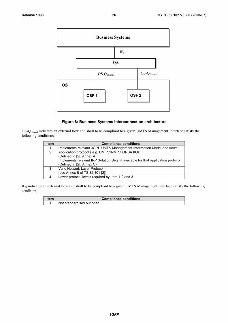
8.6 Business System interconnection architectureThe business management layer has in the second-generation systems a very low degree of standardisation. Operatorshave legacy systems or more IT influenced systems often adopted to every organisations different needs. Businesssystems are not a part of a UMTS TMN.
3GPP
3G TS 32.102 V3.2.0 (2000-07)26Release 1999
Business Systems
QA
OSF 1 OSF 2
OS-QExternal OS-QExternal
OS
IFx
Figure 8: Business Systems interconnection architecture
OS-QExteral Indicates an external flow and shall to be compliant to a given UMTS Management Interface satisfy thefollowing conditions:
Item Compliance conditions1 Implements relevant 3GPP UMTS Management Information Model and flows2 Application protocol ( e.g. CMIP,SNMP,CORBA IIOP)
(Defined in [2], Annex A)Implements relevant IRP Solution Sets, if available for that application protocol.(Defined in [2], Annex C)
3 Valid Network Layer Protocol(see Annex B of TS 32.101 [2])
4 Lower protocol levels required by Item 1,2 and 3
IFX indicates an external flow and shall to be compliant to a given UMTS Management Interface satisfy the followingcondition:
Item Compliance conditions1 Not standardised but open
3GPP
3G TS 32.102 V3.2.0 (2000-07)27Release 1999
9 TMN applicationsTelecom management applications can be implemented in many different ways depending on constraints presented inprevious clauses of the present document. Consistent operational processes are required for the management of thenetwork irrespective of vendor equipment. A mobile operator can because of the very heterogeneous nature of theirnetworks easily end of with dozens of duplicated applications for e g alarm surveillance. Most vendors of networkequipment offers dedicated net-element managers and the ones not built with an open system approach will severelylimit the possibility to report and manage the network in a consistent way.
Network element vendors with closed and unique net-element managers or operations systems with closed interfacesor interfaces with low level off openness will not fulfil the basic requirements as a part of a UMTS. It will not bepossible to design and build the telecom management network to support the operational processes as required. Suchphysical entities are not under consideration in the present document.
Many TM application functions can be identified as generic functions used by all major types of telecom equipment.Alarm surveillance applications and performance analysing applications are generic necessities to manage mostnetwork elements. Security and system management applications are also common to many TM components and maybe the scope for overall business policies.
To identify and specify the design criteria that will allow re-usable application components to be developed acrossmultiple telecom business scenarios are important issues to fulfil the basic UMTS Management requirement. "Tominimise the costs of managing a UMTS network such that it is a small component of the overall operating cost".
The implication of the top down approach in the standardising work of UMTS is that consistent operationalmanagement processes are required irrespective of vendor equipment.
Generic management applications is required to facilitate:
- Reduced management application development costs.
- Simplification of operational processes and associated reduction in costs.
- Reduced time to deploy new services as management systems already exist.
- Consistent representation of basic information.
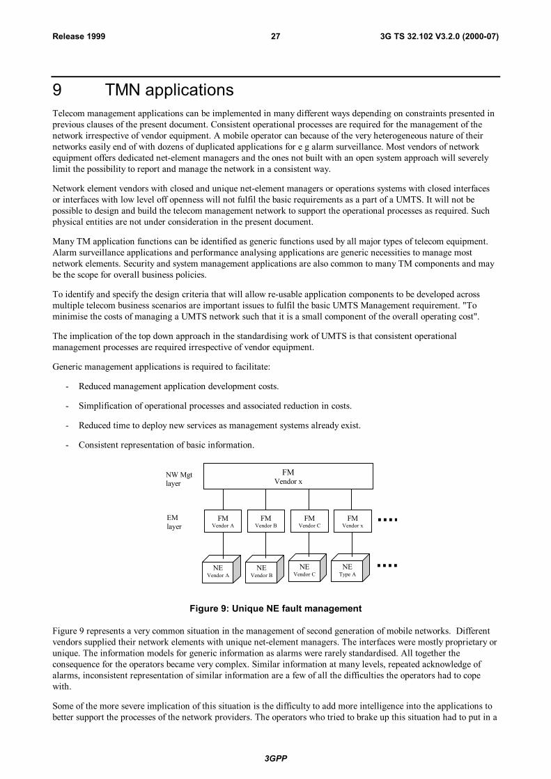
NEVendor A
NEVendor B
NW Mgtlayer
EMlayer
FMVendor A
FMVendor B
FMVendor x
NEVendor C
FMVendor C
NEType A
FMVendor x
Figure 9: Unique NE fault management
Figure 9 represents a very common situation in the management of second generation of mobile networks. Differentvendors supplied their network elements with unique net-element managers. The interfaces were mostly proprietary orunique. The information models for generic information as alarms were rarely standardised. All together theconsequence for the operators became very complex. Similar information at many levels, repeated acknowledge ofalarms, inconsistent representation of similar information are a few of all the difficulties the operators had to copewith.
Some of the more severe implication of this situation is the difficulty to add more intelligence into the applications tobetter support the processes of the network providers. The operators who tried to brake up this situation had to put in a
3GPP
3G TS 32.102 V3.2.0 (2000-07)28Release 1999
lot of effort into software development and proprietary interfaces. The marketplace did not support the needs of theoperators.
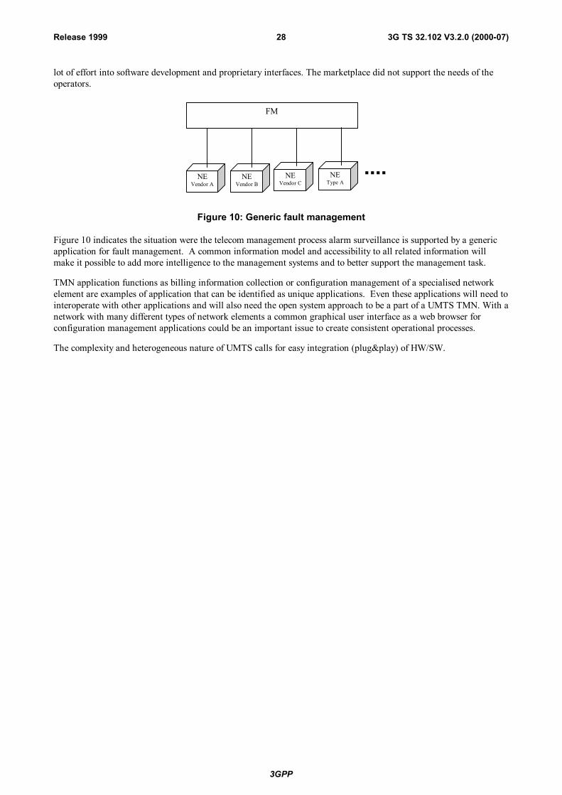
NEVendor A
NEVendor B
FM
NEVendor C
NEType A
Figure 10: Generic fault management
Figure 10 indicates the situation were the telecom management process alarm surveillance is supported by a genericapplication for fault management. A common information model and accessibility to all related information willmake it possible to add more intelligence to the management systems and to better support the management task.
TMN application functions as billing information collection or configuration management of a specialised networkelement are examples of application that can be identified as unique applications. Even these applications will need tointeroperate with other applications and will also need the open system approach to be a part of a UMTS TMN. With anetwork with many different types of network elements a common graphical user interface as a web browser forconfiguration management applications could be an important issue to create consistent operational processes.
The complexity and heterogeneous nature of UMTS calls for easy integration (plug&play) of HW/SW.
3GPP
3G TS 32.102 V3.2.0 (2000-07)29Release 1999
10 Integration Reference Points (IRPs)
10.1 GeneralRelating to the OSI functional areas "FCAPS", IRPs are here introduced addressing parts of "FCPS" – Fault,Configuration, Performance, and Security management. Comparing with TMF TOM (Telecom Operations Map) [20],the introduced IRPs address process interfaces at the EML-NML (Element Management Layer – NetworkManagement Layer) boundary. In 3GPP/SA5 context, this can also be applied to the Itf-N between EM-NM and NE-NM.
The three cornerstones of the IRP concept are:
- Top-down, process-driven modelling approachThe purpose of each IRP is automation of one specific task, related to TMF TOM. This allows taking a "onestep at a time" approach with a focus on the most important tasks.
- Protocol-independent modellingEach IRP consists of a protocol-independent model (the IRP information model) and several protocol-dependent models (IRP solution sets).
- Standard based protocol dependent modellingModels in different IRP solution sets (CMIP, SNMP, WBEM etc.) will be different as existing standard modelsof the corresponding protocol environment need to be considered. The means that solution sets largely need tobe "hand crafted".
10.2 Integration levelsVirtually all types of telecom/datacom networks comprise many different technologies purchased from severaldifferent vendors. This implies that the corresponding management solution need to be built by integrating product-specific applications from different vendors with a number of generic applications that each provide some aspect ofmulti-vendor and/or multi-technology support. A complete management solution is thus composed of severalindependent applications.
The following levels of integration are defined:
- Screen Integration: Each application provides its own specific graphical user interface (GUI) that need to beaccessible from a single, unified screen (a common desktop). A seamless integration between the various GUIsis then required. Screen Integration will not be standardised in the present document.
- Application Integration: Applications need to interwork, on a machine-machine basis, in order to automatevarious end-to-end processes of a communication provider.
10.2.1 Application integrationInterfaces related to application integration can be divided in the following three categories:
- High-level generic interfaces between generic applications on the network and service management layers.The same approach and concepts apply for these as the next category:
- High-level (technology-independent to the extent possible) interfaces between product-specific and genericapplications are needed in order to automate and streamline frequently occurring tasks applicable to severaltypes of network elements. A top-down approach shall be taken when defining these interfaces, where the maininput is (1) business processes of a communication provider, and (2) the types of generic applications that areused to implement the process support. The interfaces need to be stable, open and (preferably) standardised.These IRPs are discussed below under the heading Network Infrastructure IRPs.
3GPP
3G TS 32.102 V3.2.0 (2000-07)30Release 1999
- Detailed (product-specific) interfaces between product-specific applications and the corresponding networkelements are of course also needed. These interfaces are defined using the traditional bottom-up approach,where the actual network infrastructure is modelled. This is the traditional TMN approach to elementmanagement. The management information in these interfaces is not further discussed in this document, as it isinternal to a specific development organisation and does not need to be open. In fact, by publishing themanagement information in these interfaces, too much of the internal design may be revealed and it maybecome impossible to later enhance the systems that are using the interfaces. The management services(operations and notifications) and protocol shall however be open and standardised as long as they areindependent of the NRM describing the managed NEs/NRs.
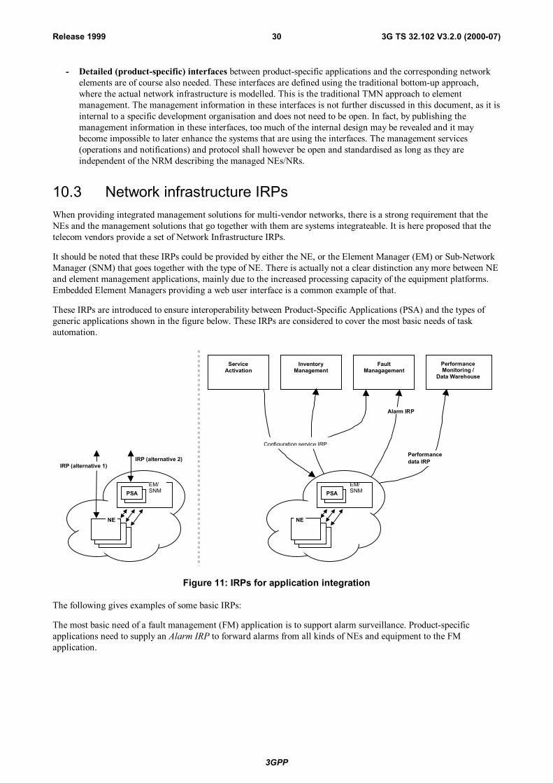
10.3 Network infrastructure IRPsWhen providing integrated management solutions for multi-vendor networks, there is a strong requirement that theNEs and the management solutions that go together with them are systems integrateable. It is here proposed that thetelecom vendors provide a set of Network Infrastructure IRPs.
It should be noted that these IRPs could be provided by either the NE, or the Element Manager (EM) or Sub-NetworkManager (SNM) that goes together with the type of NE. There is actually not a clear distinction any more between NEand element management applications, mainly due to the increased processing capacity of the equipment platforms.Embedded Element Managers providing a web user interface is a common example of that.
These IRPs are introduced to ensure interoperability between Product-Specific Applications (PSA) and the types ofgeneric applications shown in the figure below. These IRPs are considered to cover the most basic needs of taskautomation.
Alarm IRP
ServiceActivation
Performancedata IRP
InventoryManagement
PerformanceMonitoring /
Data Warehouse
FaultManagagement
NE
PSA
NE
PSA
IRP (alternative 2)IRP (alternative 1)
EM/SNM
Configuration service IRP
EM/SNM
Figure 11: IRPs for application integration
The following gives examples of some basic IRPs:
The most basic need of a fault management (FM) application is to support alarm surveillance. Product-specificapplications need to supply an Alarm IRP to forward alarms from all kinds of NEs and equipment to the FMapplication.
3GPP
3G TS 32.102 V3.2.0 (2000-07)31Release 1999
A Basic Configuration Management IRP is needed for management of topology and logical resources in the network(retrieval of the configuration and status of the network elements). It can also be used by inventory managementapplications, to track individual pieces of equipment and related data, as well as for all types of ConfigurationManagement e.g. Service Activation applications, as a provisioning interface for frequent configuration activities thatrequire automation. This IRP defines an IRP Information Model, covering both an IRP Information Service and aNetwork Resource Model.
Performance Monitoring (PM) information is made available through the Performance Data IRP.
It is realised that the Alarm IRP, Performance Data IRP and Basic Configuration Management IRP all have similarneeds to use notifications. The corresponding service is formalised as a Notification IRP. It specifies: firstly, aninterface through which subscriptions to different types of notifications can be set up (or cancelled), and secondly,common attributes for all notifications.
Further, applying a common Name Convention for Managed Objects is useful for co-operating applications thatrequire identical interpretation of names assigned to network resources under management.
10.4 Defining the IRPsIt is important to avoid dependency on one specific technology, as the technologies will change over time.Applications need to be future-proof; One fundamental principle for achieving this is to clearly separate informationmodels from protocols for the external interfaces, where the information models are more important than the selectionof protocols.
Thus, the detailed IRP specifications are divided into two main parts, following the directives from TMF’s SMARTTMN:
• Information models specified with an implementation neutral modelling language. The Unified Modellinglanguage (UML) has been selected, as it is standardised (by OMG), supported by most object-oriented tools andused in several ongoing standardisation efforts (CIM etc.).
• Solution sets, i.e. mappings of the information models to one or several protocols (CORBA/IDL, SNMP/SMI,CMIP/GDMO, COM/IDL etc.). Different protocol selections may be done for different IRPs.
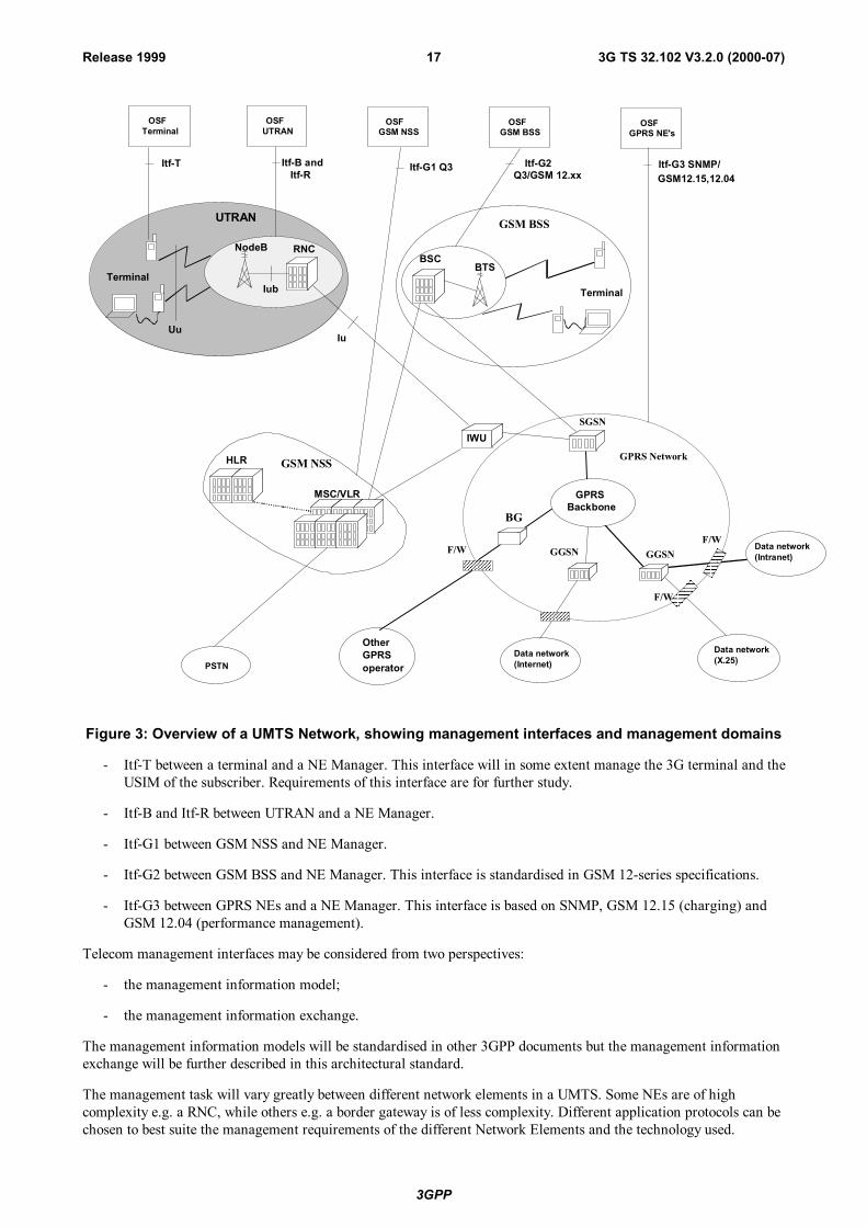
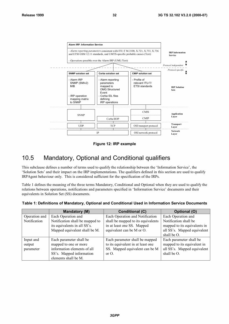
Figure 12 shows an example of how an IRP can be structured (the Alarm IRP).
3GPP
3G TS 32.102 V3.2.0 (2000-07)32Release 1999
Figure 12: IRP example
10.5 Mandatory, Optional and Conditional qualifiersThis subclause defines a number of terms used to qualify the relationship between the ‘Information Service’, the‘Solution Sets’ and their impact on the IRP implementations. The qualifiers defined in this section are used to qualifyIRPAgent behaviour only. This is considered sufficient for the specification of the IRPs.
Table 1 defines the meaning of the three terms Mandatory, Conditional and Optional when they are used to qualify therelations between operations, notifications and parameters specified in ‘Information Service’ documents and theirequivalents in Solution Set (SS) documents.
Table 1: Definitions of Mandatory, Optional and Conditional Used in Information Service Documents
Mandatory (M) Conditional (C) Optional (O)Operation andNotification
Each Operation andNotification shall be mapped toits equivalents in all SS’s.Mapped equivalent shall be M.
Each Operation and Notificationshall be mapped to its equivalentsin at least one SS. Mappedequivalent can be M or O.
Each Operation andNotification shall bemapped to its equivalents inall SS’s. Mapped equivalentshall be O.
Input andoutputparameter
Each parameter shall bemapped to one or moreinformation elements of allSS’s. Mapped informationelements shall be M.
Each parameter shall be mappedto its equivalent in at least oneSS. Mapped equivalent can be Mor O.
Each parameter shall bemapped to its equivalent inall SS’s. Mapped equivalentshall be O.
IRP SolutionSets
ApplicationLayer
Protocol independent
Protocol specific
IRP InformationService
Corba/IIOP
Alarm IRP: Information Service
- Alarm reporting parameters consistent with ITU-T M.3100, X.721, X.733, X.736and ETSI GSM 12.11 standards, and UMTS-specific probable causes (Text)
- Operations possible over the Alarm IRP (UML/Text)
SNMP solution set
- Alarm IRP SNMP (SMIv2) MIB
- IRP operation mapping matrix to SNMP
Corba solution set
- Alarm reporting parameters mapped to OMG Structured Event- Corba IDL files defining IRP operations
SNMP
TransportLayer
NetworkLayer
UDP TCP
IP
CMIP solution set
- Profile of relevant ITU-T/ ETSI standards
OSI network protocol
OSI transport protocol
CMIS
CMIP
3GPP
3G TS 32.102 V3.2.0 (2000-07)33Release 1999
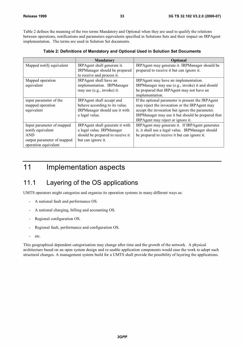
Table 2 defines the meaning of the two terms Mandatory and Optional when they are used to qualify the relationsbetween operations, notifications and parameters equivalents specified in Solutions Sets and their impact on IRPAgentimplementation. The terms are used in Solution Set documents.
Table 2: Definitions of Mandatory and Optional Used in Solution Set Documents
Mandatory OptionalMapped notify equivalent IRPAgent shall generate it.
IRPManager should be preparedto receive and process it.
IRPAgent may generate it. IRPManager should beprepared to receive it but can ignore it.
Mapped operationequivalent
IRPAgent shall have animplementation. IRPManagermay use (e.g., invoke) it.
IRPAgent may have an implementation.IRPManager may use (e.g., invoke) it and shouldbe prepared that IRPAgent may not have animplementation.
input parameter of themapped operationequivalent
IRPAgent shall accept andbehave according to its value.IRPManager should use it witha legal value.
If the optional parameter is present the IRPAgentmay reject the invocation or the IRPAgent mayaccept the invocation but ignore the parameter.IRPManager may use it but should be prepared thatIRPAgent may reject or ignore it.
Input parameter of mappednotify equivalentANDoutput parameter of mappedoperation equivalent
IRPAgent shall generate it witha legal value. IRPManagershould be prepared to receive itbut can ignore it.
IRPAgent may generate it. If IRPAgent generatesit, it shall use a legal value. IRPManager shouldbe prepared to receive it but can ignore it.
11 Implementation aspects
11.1 Layering of the OS applicationsUMTS operators might categories and organise its operation systems in many different ways as:
- A national fault and performance OS.
- A national charging, billing and accounting OS.
- Regional configuration OS.
- Regional fault, performance and configuration OS.
- etc.
This geographical dependent categorisation may change after time and the growth of the network. A physicalarchitecture based on an open system design and re-usable application components would ease the work to adopt suchstructural changes. A management system build for a UMTS shall provide the possibility of layering the applications.
3GPP
3G TS 32.102 V3.2.0 (2000-07)34Release 1999
12 TMN planning and design considerationsA TMN should be designed such that it has the capability to interface with several types of communications paths toensure that a framework is provided which is flexible enough to allow for the most efficient communications:
- Between one NE and other elements within the TMN;
- Between a WS and other elements within the TMN;
- Between elements within the TMN;
- Between TMNs.
The basis for choosing the appropriate interfaces, however, should be the functions performed by the elements betweenwhich appropriate communications are performed. The interface requirements are specified in terms of functionattributes needed to provide the most efficient interface.
12.1 Function attributesa) Reliability – The capability of the interface to ensure that data and control are transferred such that integrity
and security are maintained.
b) Frequency – How often data is transferred across the interface boundary (Normal behaviour).
c) Quantity – The amount of data that is transferred across the interface during any transaction.
d) Priority – Indicates precedence to be given to data in case of competition for network resources with otherfunctions.
e) Availability – Determines the use of redundancy in the design of the communications channels betweeninterfacing elements.
f) Delay – Identifies the amount of buffering that may be tolerable between interfacing elements. This alsoimpacts communications channel designs.
3GPP
3G TS 32.102 V3.2.0 (2000-07)35Release 1999
Table 3 suggests a possible ranges for these function attributes.
Table 3: Possible ranges for TMN function attributes [1]
Attributes Requirements Nature of attributes
Delay (speed)ShortMediumLong
Performance or grade of service (P)Reliability(accuracy)
HighMediumLow
Objective of design and control(acceptable/unacceptable butavailable/unavailable)
AvailabilityHighMediumLow
QuantityLargeMediumSmall
Characteristics of TMN traffic (C) FrequencyOften continuousPeriodicSparse
Condition or parameter of design
PriorityHighMediumLow
12.2 Functional characteristicsEach major type of telecommunications equipment has functional characteristic needs that can be used to describe thecomplexity of the interface.
There are, however, a basic group of TMN application functions that cross all major types of telecommunicationsequipment. There are also unique TMN application functions that are performed by specific categories of majortelecommunications equipment. Alarm surveillance is an example of the former, whereas billing informationcollection is an example of the latter.
Functional characteristics of the elements within a TMN, e.g. OS, DCN and MD also describe the complexity ofinterfaces between these elements.
12.3 Critical attributesAttribute values for a given function are generally consistent across the network elements.
When considering a single interface, it is important to identify the controlling attribute ranges for the design of theinterface.
If there are conflicting attribute values for different functions in a given network element, more than one instance ofan interface may be needed.
Overall TMN attribute values for the interfacing of elements within the TMN depend on the type and number offunctions performed within these elements. In this case the functions are not consistent across TMN elements, but arecontrolled by the individual TMN design of an Administration.
12.4 Protocol selection In many cases, more than one protocol suite will meet the requirements for the network element or TMN elementunder consideration. It is the approach for the 3GPP Telecom management standardisation to concentrate on protocolindependent information models, allowing the mapping to several protocol suites.
3GPP
3G TS 32.102 V3.2.0 (2000-07)36Release 1999
The rational behind this is:
- The blurring of Information and Telecommunication technologies in UMTS, it is required to work on a moreopen approach (acknowledging the market status and foreseen evolutions).
- The life-cycle of information flows is 10 to 20 years, while the protocols is 5 to 10 years.
- The developments on automatic conversion allows for a more pragmatic and open approach.
The choice of the individual protocol from the recommended family will be left open to the vendors and operators.
To provide the most efficient interface care should be taken to select the protocol suite that optimises the relationshipbetween the total cost to implement that protocol suite, the functional attributes and the data communications channelsthat carry the information across the interface.
12.5 Communications considerationsDCN architectures shall be planned and designed to ensure that their implementation provides appropriate degrees ofavailability and network delay while minimising cost.
One shall consider the selection of communications architectures, e.g. star, multipoint, loop, tree, etc..
The communications channels, e.g. dedicated lines, circuit-switched networks and packet networks used in providingthe communications paths, also play an important role.
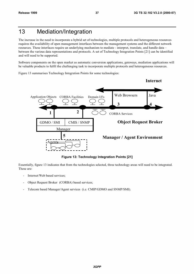
3GPP
3G TS 32.102 V3.2.0 (2000-07)37Release 1999
13 Mediation/IntegrationThe increase in the need to incorporate a hybrid set of technologies, multiple protocols and heterogeneous resourcesrequires the availability of open management interfaces between the management systems and the different networkresources. These interfaces require an underlying mechanism to mediate - interpret, translate, and handle data –between the various data representations and protocols. A set of Technology Integration Points [21] can be identifiedand will need to be supported.
Software components on the open market as automatic conversion applications, gateways, mediation applications willbe valuable products to fulfil the challenging task to incorporate multiple protocols and heterogeneous resources.
Figure 13 summarises Technology Integration Points for some technologies:
Application Objects CORBA Facilities Domain I/Fs
Object Request Broker
Agents
CORBA Services
Web Browsers Java
Internet
1 2
3 4
CMIS / SNMPGDMO / SMI
Manager
Manager / Agent Environment5
Figure 13: Technology Integration Points [21]
Essentially, figure 13 indicates that from the technologies selected, three technology areas will need to be integrated.These are:
- Internet/Web based services;
- Object Request Broker (CORBA) based services;
- Telecom based Manager/Agent services (i.e. CMIP/GDMO and SNMP/SMI).
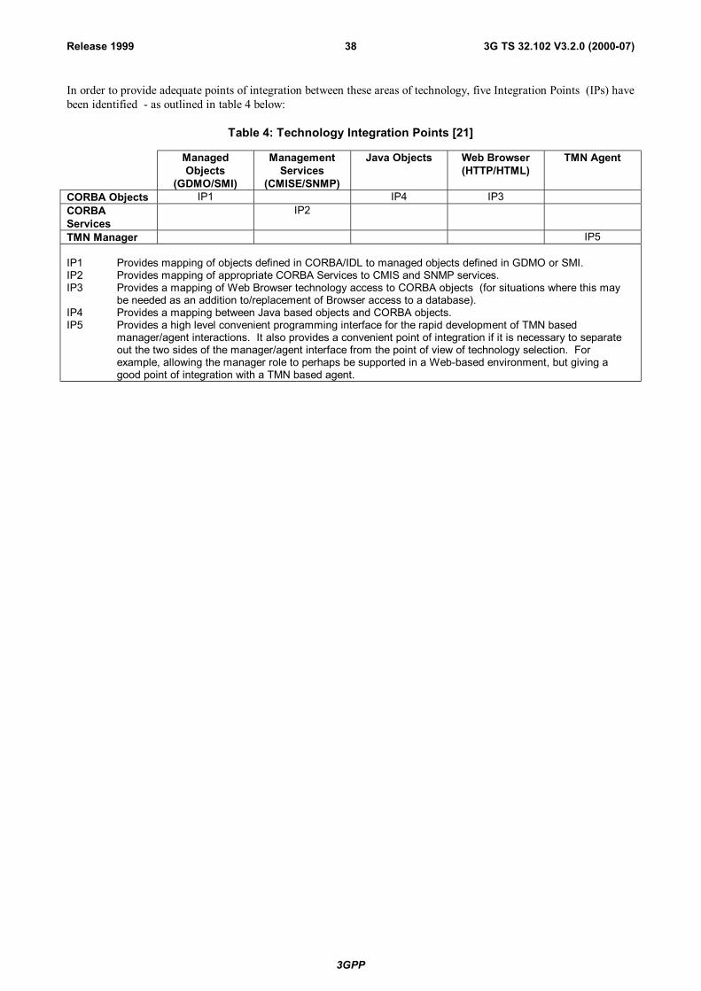
3GPP
3G TS 32.102 V3.2.0 (2000-07)38Release 1999
In order to provide adequate points of integration between these areas of technology, five Integration Points (IPs) havebeen identified - as outlined in table 4 below:
Table 4: Technology Integration Points [21]
ManagedObjects
(GDMO/SMI)
ManagementServices
(CMISE/SNMP)
Java Objects Web Browser(HTTP/HTML)
TMN Agent
CORBA Objects IP1 IP4 IP3CORBAServices
IP2
TMN Manager IP5
IP1 Provides mapping of objects defined in CORBA/IDL to managed objects defined in GDMO or SMI.IP2 Provides mapping of appropriate CORBA Services to CMIS and SNMP services.IP3 Provides a mapping of Web Browser technology access to CORBA objects (for situations where this may
be needed as an addition to/replacement of Browser access to a database).IP4 Provides a mapping between Java based objects and CORBA objects.IP5 Provides a high level convenient programming interface for the rapid development of TMN based
manager/agent interactions. It also provides a convenient point of integration if it is necessary to separateout the two sides of the manager/agent interface from the point of view of technology selection. Forexample, allowing the manager role to perhaps be supported in a Web-based environment, but giving agood point of integration with a TMN based agent.
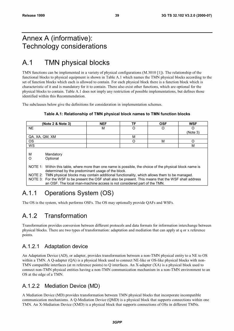
3GPP
3G TS 32.102 V3.2.0 (2000-07)39Release 1999
Annex A (informative):Technology considerations
A.1 TMN physical blocksTMN functions can be implemented in a variety of physical configurations (M.3010 [1]). The relationship of thefunctional blocks to physical equipment is shown in Table A.1 which names the TMN physical blocks according to theset of function blocks which each is allowed to contain. For each physical block there is a function block which ischaracteristic of it and is mandatory for it to contain. There also exist other functions, which are optional for thephysical blocks to contain. Table A.1 does not imply any restriction of possible implementations, but defines thoseidentified within this Recommendation.
The subclauses below give the definitions for consideration in implementation schemes.
Table A.1: Relationship of TMN physical block names to TMN function blocks
(Note 2 & Note 3) NEF TF OSF WSFNE M O O O
(Note 3)QA, XA, QM, XM MOS O M OWS M
M MandatoryO Optional
NOTE 1: Within this table, where more than one name is possible, the choice of the physical block name isdetermined by the predominant usage of the block.
NOTE 2: TMN physical blocks may contain additional functionality, which allows them to be managed.NOTE 3: For the WSF to be present the OSF shall also be present. This means that the WSF shall address
an OSF. The local man-machine access is not considered part of the TMN.
A.1.1 Operations System (OS)The OS is the system, which performs OSFs. The OS may optionally provide QAFs and WSFs.
A.1.2 TransformationTransformation provides conversion between different protocols and data formats for information interchange betweenphysical blocks. There are two types of transformation: adaptation and mediation that can apply at q or x referencepoints.
A.1.2.1 Adaptation deviceAn Adaptation Device (AD), or adapter, provides transformation between a non-TMN physical entity to a NE to OSwithin a TMN. A Q-adapter (QA) is a physical block used to connect NE-like or OS-like physical blocks with non-TMN compatible interfaces (at m reference points) to Q interfaces. An X-adapter (XA) is a physical block used toconnect non-TMN physical entities having a non-TMN communication mechanism in a non-TMN environment to anOS at the edge of a TMN.
A.1.2.2 Mediation Device (MD)A Mediation Device (MD) provides transformation between TMN physical blocks that incorporate incompatiblecommunication mechanisms. A Q-Mediation Device (QMD) is a physical block that supports connections within oneTMN. An X-Mediation Device (XMD) is a physical block that supports connections of OSs in different TMNs.
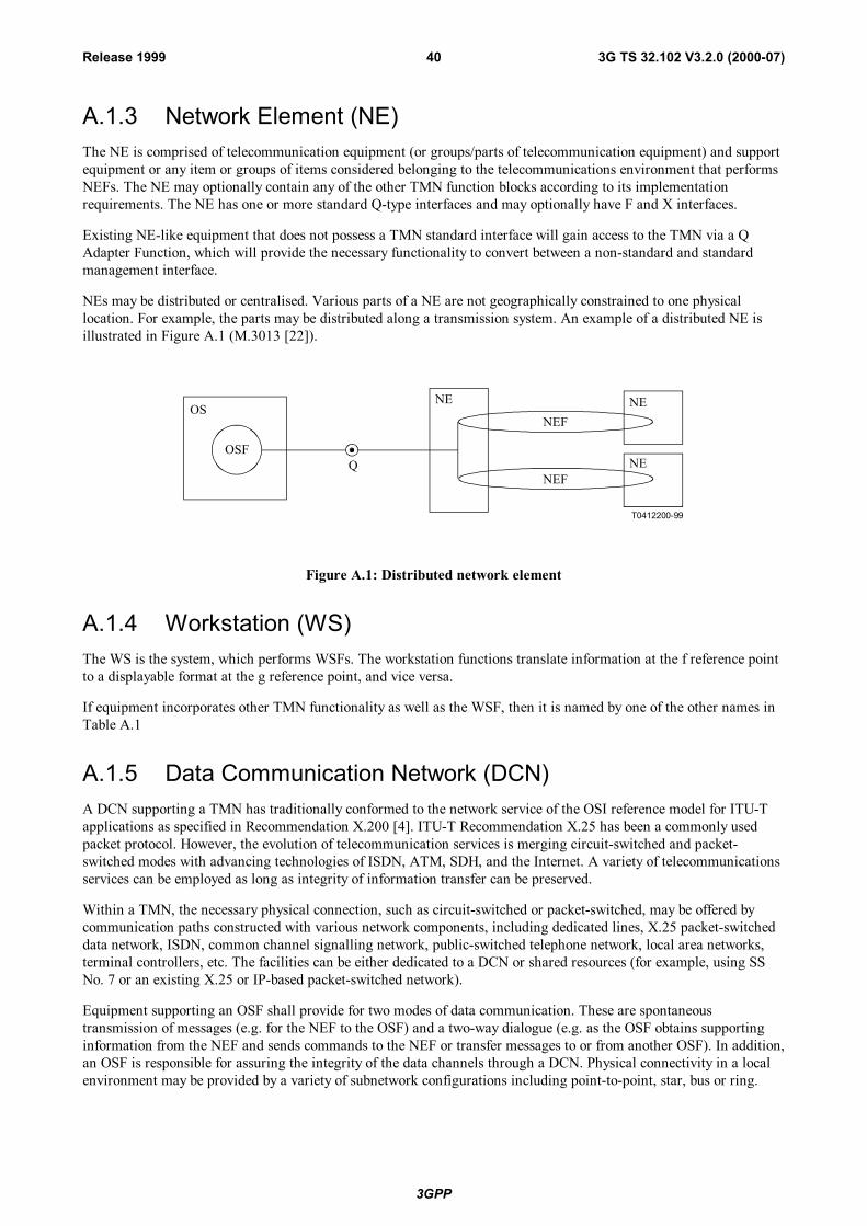
3GPP
3G TS 32.102 V3.2.0 (2000-07)40Release 1999
A.1.3 Network Element (NE)The NE is comprised of telecommunication equipment (or groups/parts of telecommunication equipment) and supportequipment or any item or groups of items considered belonging to the telecommunications environment that performsNEFs. The NE may optionally contain any of the other TMN function blocks according to its implementationrequirements. The NE has one or more standard Q-type interfaces and may optionally have F and X interfaces.
Existing NE-like equipment that does not possess a TMN standard interface will gain access to the TMN via a QAdapter Function, which will provide the necessary functionality to convert between a non-standard and standardmanagement interface.
NEs may be distributed or centralised. Various parts of a NE are not geographically constrained to one physicallocation. For example, the parts may be distributed along a transmission system. An example of a distributed NE isillustrated in Figure A.1 (M.3013 [22]).
T0412200-99
OS
OSFQ
NE NE
NE
NEF
NEF
Figure A.1: Distributed network element
A.1.4 Workstation (WS)The WS is the system, which performs WSFs. The workstation functions translate information at the f reference pointto a displayable format at the g reference point, and vice versa.
If equipment incorporates other TMN functionality as well as the WSF, then it is named by one of the other names inTable A.1
A.1.5 Data Communication Network (DCN)A DCN supporting a TMN has traditionally conformed to the network service of the OSI reference model for ITU-Tapplications as specified in Recommendation X.200 [4]. ITU-T Recommendation X.25 has been a commonly usedpacket protocol. However, the evolution of telecommunication services is merging circuit-switched and packet-switched modes with advancing technologies of ISDN, ATM, SDH, and the Internet. A variety of telecommunicationsservices can be employed as long as integrity of information transfer can be preserved.
Within a TMN, the necessary physical connection, such as circuit-switched or packet-switched, may be offered bycommunication paths constructed with various network components, including dedicated lines, X.25 packet-switcheddata network, ISDN, common channel signalling network, public-switched telephone network, local area networks,terminal controllers, etc. The facilities can be either dedicated to a DCN or shared resources (for example, using SSNo. 7 or an existing X.25 or IP-based packet-switched network).
Equipment supporting an OSF shall provide for two modes of data communication. These are spontaneoustransmission of messages (e.g. for the NEF to the OSF) and a two-way dialogue (e.g. as the OSF obtains supportinginformation from the NEF and sends commands to the NEF or transfer messages to or from another OSF). In addition,an OSF is responsible for assuring the integrity of the data channels through a DCN. Physical connectivity in a localenvironment may be provided by a variety of subnetwork configurations including point-to-point, star, bus or ring.
3GPP
3G TS 32.102 V3.2.0 (2000-07)41Release 1999
The DCN may consist of a number of individual subnetworks of different types, interconnected together. The DCNmay be a local path or a wide-area connection among distributed physical blocks. The DCN is technology independentand may employ any single or combination of transmission technologies.
A.1.6 TMN logical layered architecture within the TMN physicalarchitecture
Four specialisations of the OS physical block are defined to support a physical realisation of function blocks in logicallayers. The four specialised OS physical blocks are the Business (B-OS), the Service (S-OS), the Network (N-OS) andthe Element (E-OS) Operations Systems. These physical blocks are named according to the predominant functionblock they contain. Specifically, B-OS, S-OS, N-OS and E-OS predominantly contain B-OSF, S-OSF, N-OSF and E-OSF respectively. When physical blocks contain more than one kind of specialised OS function block that providesubstantial functionality to the physical block, thus spanning more than one logical layer, the physical block is namedaccording to the highest hierarchically layered function block. For example, a physical block containing both N-OSFand E-OSF, providing substantial network functionality is called an N-OS.
The exchange of management information between logical layers employs the managing roles and managed roles ofthe TMN interaction model. This allows management activities to be clustered into layers and to be decoupled. Themanaged roles will be associated with a set of information elements from information model(s) exposing a view at thelayer's level of abstraction (e.g. equipment, element, network, service, etc.). Generally, managing and managed rolesmay be placed in logical layers without restriction. A managed role may be associated with a set of informationelements from any layer. Managed roles may be placed in any layer and invoke operations associated with any othermanaged roles.
A.1.7 Interoperable interface conceptIn order for two or more TMN physical blocks to exchange management information they shall be connected by acommunications path and each element shall support the same interface onto that communications path.
It is useful to use the concept of an interoperable interface to simplify the communications problems arising from amulti-vendor, multi-capability network.
The interoperable interface defines the protocol suite and the messages carried by the protocol. Transaction-orientedinteroperable interfaces are based upon an object-oriented view of the communication and therefore, all the messagescarried deal with object manipulations. It is the formally defined set of protocols, procedures, message formats andsemantics used for the management communications.
The message component of the interoperable interface provides a generalised mechanism for managing the objectsdefined for the information model. As part of the definition of each object there is a list of management operationstypes which are valid for the object. In addition, there are generic messages that are used identically for many classesof managed objects.
In the architecture, what predominantly distinguishes one interface from another is the scope of the managementactivity that the communication at the interface shall support. This common understanding of the scope of operation istermed Shared Management Knowledge. Shared Management Knowledge includes an understanding of theinformation model of the managed network (object classes supported, functions supported, etc.), management supportobjects, options, application context supported, etc. The Shared Management Knowledge ensures that each end of theinterface understands the exact meaning of a message sent by the other end.
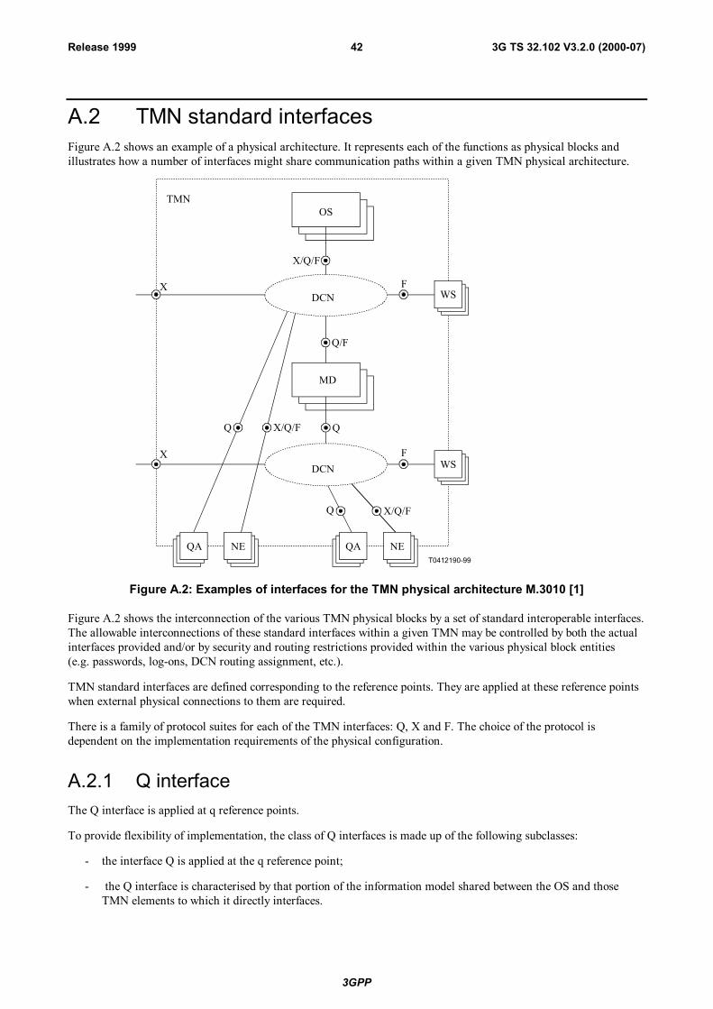
3GPP
3G TS 32.102 V3.2.0 (2000-07)42Release 1999
A.2 TMN standard interfacesFigure A.2 shows an example of a physical architecture. It represents each of the functions as physical blocks andillustrates how a number of interfaces might share communication paths within a given TMN physical architecture.
T0412190-99
OS
WS
MD
FX
Q
QA NEQA NE
Q/F
Q Q
X FWS
X/Q/F
X/Q/F
X/Q/F
TMN
DCN
DCN
Figure A.2: Examples of interfaces for the TMN physical architecture M.3010 [1]
Figure A.2 shows the interconnection of the various TMN physical blocks by a set of standard interoperable interfaces.The allowable interconnections of these standard interfaces within a given TMN may be controlled by both the actualinterfaces provided and/or by security and routing restrictions provided within the various physical block entities(e.g. passwords, log-ons, DCN routing assignment, etc.).
TMN standard interfaces are defined corresponding to the reference points. They are applied at these reference pointswhen external physical connections to them are required.
There is a family of protocol suites for each of the TMN interfaces: Q, X and F. The choice of the protocol isdependent on the implementation requirements of the physical configuration.
A.2.1 Q interfaceThe Q interface is applied at q reference points.
To provide flexibility of implementation, the class of Q interfaces is made up of the following subclasses:
- the interface Q is applied at the q reference point;
- the Q interface is characterised by that portion of the information model shared between the OS and thoseTMN elements to which it directly interfaces.
3GPP
3G TS 32.102 V3.2.0 (2000-07)43Release 1999
A.2.2 F interfaceThe F interface is applied at f reference points. The F interfaces connecting workstations to the TMN building blockscontaining OSFs or MFs through a data communication network are included in this Recommendation. Connectionsof implementation specific, WS-like entities to OSs or NEs, are not subject of this Recommendation.
A.2.3 X interfaceThe X interface is applied at the x reference point. It will be used to interconnect two TMNs or to interconnect a TMNwith other network or systems which accommodates a TMN-like interface. As such, this interface may requireincreased security over the level, which is required by a Q-type interface. It will therefore be necessary that aspects ofsecurity are addressed at the time of agreement between associations, e.g. passwords and access capabilities.
The information model at the X interface will set the limits on the access available from outside the TMN. The set ofcapabilities made available at the X interface for access to the TMN will be referred to as TMN Access.
Additional protocol requirements may be required to introduce the level of security, non-repudiation, etc. which isrequired.
A.2.4 Relationship of TMN interfaces to TMN physical blocksTable A.1 defines the possible interfaces, which each named TMN physical block can support. It is based upon thefunction blocks which Table A.1 associates with each physical block and the reference points between function blocks.
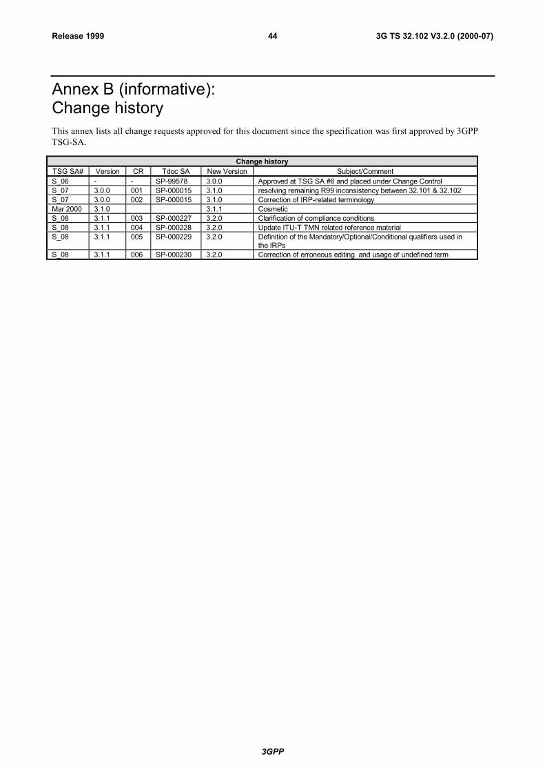
3GPP
3G TS 32.102 V3.2.0 (2000-07)44Release 1999
Annex B (informative):Change historyThis annex lists all change requests approved for this document since the specification was first approved by 3GPPTSG-SA.
Change historyTSG SA# Version CR Tdoc SA New Version Subject/CommentS_06 - - SP-99578 3.0.0 Approved at TSG SA #6 and placed under Change ControlS_07 3.0.0 001 SP-000015 3.1.0 resolving remaining R99 inconsistency between 32.101 & 32.102S_07 3.0.0 002 SP-000015 3.1.0 Correction of IRP-related terminologyMar 2000 3.1.0 3.1.1 CosmeticS_08 3.1.1 003 SP-000227 3.2.0 Clarification of compliance conditionsS_08 3.1.1 004 SP-000228 3.2.0 Update ITU-T TMN related reference materialS_08 3.1.1 005 SP-000229 3.2.0 Definition of the Mandatory/Optional/Conditional qualifiers used in
the IRPsS_08 3.1.1 006 SP-000230 3.2.0 Correction of erroneous editing and usage of undefined term


![TS-3GA-25.415(R99)v3.12.0 UTRAN Iu interface user plane ... · UTRAN Iu interface user plane protocols ... "UTRAN Iu Interface Data Transport and Transport Signalling". [5] 3GPP TS](https://static.fdocuments.in/doc/165x107/5b4d0f027f8b9ac6118bb2ed/ts-3ga-25415r99v3120-utran-iu-interface-user-plane-utran-iu-interface.jpg)