Elsevier Editorial System(tm) for European Polymer Journal ...
Upload
preetish09Category
view
539download
2description

Aw
Pa
b
a
A
R
R
2
A
K
F
I
M
1
TijaeuTppnjIliep
0d
j o u r n a l o f m a t e r i a l s p r o c e s s i n g t e c h n o l o g y 1 9 7 ( 2 0 0 8 ) 17–21
journa l homepage: www.e lsev ier .com/ locate / jmatprotec
nalysis of first mode of metal transfer in friction stirelded plates by image processing technique
reetish Sinhaa, S. Muthukumaranb,∗, S.K. Mukherjeeb
Department of Mechanical Engineering, Birla Institute of Technology, Mesra, Ranchi 835215, IndiaDepartment of Production Engineering, Birla Institute of Technology, Mesra, Ranchi 835215, India
r t i c l e i n f o
rticle history:
eceived 16 May 2006
eceived in revised form
9 May 2007
ccepted 5 June 2007
a b s t r a c t
The metal flow phenomenon in friction stir welding (FSW) comprised of two modes of metal
transfer. The first mode of metal transfer taking place layer by layer and is caused by the
shearing action of the tool shoulder, while the second mode is caused by the extrusion of the
plasticized metal around the pin. The aim of the present study is to quantitatively determine
the amount of metal transferred by the first mode and its effect on strength of the weld.
The images of the fractured faces of the samples are captured and processed to identify and
eywords:
riction stir welding
mage processing
distinguish the two modes of metal transfer. Quantitative analysis of the fractured surface
and reveals existence of a possible linear correlation between the first mode in the fractured
surface and the ultimate tensile strength, which controls the presence of defect in the weld.
© 2007 Elsevier B.V. All rights reserved.
shoulder and the plate. It is characterized by layer-by-layerdeposition of metal, one over the other. The second mode of
etal flow
. Introduction
he friction stir welding (FSW) is a solid state welding processn which a non consumable rotating welding tool is used tooin two metal pieces by frictional heat. It is especially suit-ble to low melting point metals, such as Al and Mg (Thomast al., 1991; Biallas et al., 1999). The rotating cylindrical toolsed in FSW is provided with a shoulder and a threaded pin.he shoulder heats the metal by friction and the pin stirs thelasticized material to join the two metal pieces together. Therincipal advantages of FSW over conventional welding tech-iques are low distortion, absence of melt related defects, high
oint strength and excellent mechanical properties (Bussu andrving, 2003). Consequently there is less joint contamination,esser heat affected zone and a very fine microstructure, whichncreases the tensile strength and fatigue life. Hence FSW is an
nergy efficient, environment friendly and versatile weldingrocess.∗ Corresponding author.E-mail address: [email protected] (S. Muthukumaran).
924-0136/$ – see front matter © 2007 Elsevier B.V. All rights reserved.oi:10.1016/j.jmatprotec.2007.06.013
The metal flow phenomenon in FSW is a complex processand various theories have been proposed to explain the forma-tion of the weld. Colligan (1999) studied the metal flow usingembedded steel spheres placed along the weld centre line andreported that chaotic mixing take place in the top surface ofthe weld. Xu et al. (2001) explained the flow phenomenon inFSW by performing finite element simulation. It was reportedby them that the material flow takes place from retreating side.
However, it has been recently established experimentallyby Muthukumaran and Mukherjee (2006) that the two modesof metal transfer is the fundamental mechanism that governsthe weld formation in FSW (Muthukumaran and Mukherjee,2006). According to the study the first mode of metal transferoccurs due to the frictional heat generated between the tool
metal transfer occurs by the extrusion of metal around thetool pin, when it reaches a state of sufficient plasticity. To

i n g
18 j o u r n a l o f m a t e r i a l s p r o c e s sestablish this phenomenon two techniques were employed.In the first technique a strip was welded to the plate by theFSW process, while in the second technique a brass sheet wasinserted perpendicular to the welding direction. In both thecases, the two modes of metal transfer could distinctly be seenfrom the welded specimens, thereby firmly establishing theconcept of two modes of metal transfer. Also it was provedthat metal extrusion could take place from either the retreat-ing side towards the forwarding side, or it could also occurfrom both retreating and forwarding sides (Muthukumaranand Mukherjee, 2006).
Cavaliere et al. (2006a,b) performed FSW on dissimilar 2024and 7075 Al alloy sheets, in the T3 and T6 conditions, respec-tively. They examined fatigue and tensile fractured specimensurfaces for microscopic morphology and defect analysis.Elangovan and Balasubramanian (2007) observed that thesquare pin profiled tool gives defect free joint with better ten-sile property.
The present work investigates the correlation betweenthe quantity of first mode of metal transfer and the tensilestrength of the friction stir welded specimens. The boundarybetween the two modes of metal transfer is not distinct in themacro structure of some welds. However when the fractureoccurs in the weld they are distinct. Hence in the present workan attempt is made to correlate the tensile strength with thefirst mode with the help of fractured surfaces. Specimen areprepared from friction stir welded aluminium plates and frac-tured by tensile load. The images of these fractured specimensare analyzed using image processing techniques to quantita-tively determine the first mode of metal transfer.
The macrostructure of a friction stir welded plate havingtwo distinct modes of metal transfer is shown in Fig. 1. The
layers of metal deposited at the top represent the first modeof metal transfer while the layers below represents the secondmode, where definite ring patterns can be observed. In general,friction stir welded macrostructure has four zones. The firstFig. 1 – Macrostructure showing distinct first and secondmode of metal transfer.
t e c h n o l o g y 1 9 7 ( 2 0 0 8 ) 17–21
and second zones are unaffected base metal and heat affectedzone (HAZ), respectively. In HAZ the material does not undergoany plastic deformation but is influenced by the heat of thewelding, leading to some changes in the macrostructure. Thethird is the thermo-mechanically affected zone (TMAZ), wherethe material is deformed as well as influenced by heat. Thefourth zone is the nugget, which is the recrystallized regionof the TMAZ (Cavaliere et al., 2006a,b; Prangnell and Heason,2005).
2. Experimental work
Friction stir welding tools with threaded pins are employedto butt weld 6.3 mm plates of 6063-T4 aluminium alloy. TheFSW is carried with a modified 2369-0 HMT Universal Millingmachine. The tool material used is ‘tool steel’ and the tool hasa 16 mm shoulder diameter and a M6 threaded pin. The rakeangle provided for all the experiments is 1◦. The rotating speedof the tool and its traverse speed are varied between the rangesof 900–1120 rpm and 100–200 mm/min, respectively. The ten-sile specimens are prepared as per ASTM standard and testedin the hydraulic tensile testing machine.
The principle parameters in the FSW process are the rota-tional tool speed, tool travel speed and the pin length. Avariation in these parameters affects the quantity of metaltransferred by the first mode as well as the second mode, thusaffecting the tensile strength.
3. Image processing and analysis
The captured images of the fractured samples are analysed inMATLAB by implementing the following steps:
(1) The preliminary pre processing stage consists of apply-ing filtering techniques to eliminate the noise from theacquired images, thereby sharpening the image.
(2) Next a portion of the original image is cropped to selectthe region of interest.
(3) Then the cropped image is converted to an 8-bit grayscaleintensity image for further analysis.
(4) The graylevel image is equalised to improve its contrast byhistogram equalisation techniques.
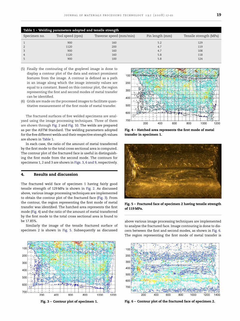
Fig. 2 – Fractured weld face of specimen 1 having tensilestrength of 129 MPa.
j o u r n a l o f m a t e r i a l s p r o c e s s i n g t e c h n o l o g y 1 9 7 ( 2 0 0 8 ) 17–21 19
Table 1 – Welding parameters adopted and tensile strength
Specimen no. Tool speed (rpm) Traverse speed (mm/min) Pin length (mm) Tensile strength (MPa)
1 900 160 5.2 1292 1120 200 4.7 119
4.7 1085.8 1185.8 124
(
(
yaafa
bTis
4
Ttatttmbb
s
Fig. 4 – Hatched area represents the first mode of metaltransfer in specimen 1.
3 900 1604 1120 1605 900 100
5) Finally the contouring of the graylevel image is done todisplay a contour plot of the data and extract prominentfeatures from the image. A contour is defined as a pathin an image along which the image intensity values areequal to a constant. Based on this contour plot, the regionrepresenting the first and second modes of metal transfercan be identified.
6) Grids are made on the processed images to facilitate quan-titative measurement of the first mode of metal transfer.
The fractured surfaces of five welded specimens are anal-sed using the image processing techniques. Three of themre shown through Fig. 2 and Fig. 10. The welds are prepareds per the ASTM Standard. The welding parameters adoptedor the five different welds and their respective strength valuesre shown in Table 1.
In each case, the ratio of the amount of metal transferredy the first mode to the total cross sectional area is computed.he contour plot of the fractured face is useful in distinguish-
ng the first mode from the second mode. The contours forpecimens 1, 2 and 3 are shown in Figs. 3, 6 and 9, respectively.
. Results and discussion
he fractured weld face of specimen 1 having fairly goodensile strength of 129 MPa is shown in Fig. 2. As discussedbove, various image processing techniques are implementedo obtain the contour plot of the fractured face (Fig. 3). Fromhe contour, the region representing the first mode of metalransfer was identified. The hatched area represents the first
ode (Fig. 4) and the ratio of the amount of metal transferred
y the first mode to the total cross sectional area is found toe 17.85%.Similarly the image of the tensile fractured surface ofpecimen 2 is shown in Fig. 5. Subsequently as discussed
Fig. 3 – Contour plot of specimen 1.
Fig. 5 – Fractured face of specimen 2 having tensile strengthof 119 MPa.
above various image processing techniques are implementedto analyse the fractured face. Image contouring is done to dis-cern between the first and second modes, as shown in Fig. 6.The region representing the first mode of metal transfer is
Fig. 6 – Contour plot of the fractured face of specimen 2.
20 j o u r n a l o f m a t e r i a l s p r o c e s s i n g t e c h n o l o g y 1 9 7 ( 2 0 0 8 ) 17–21
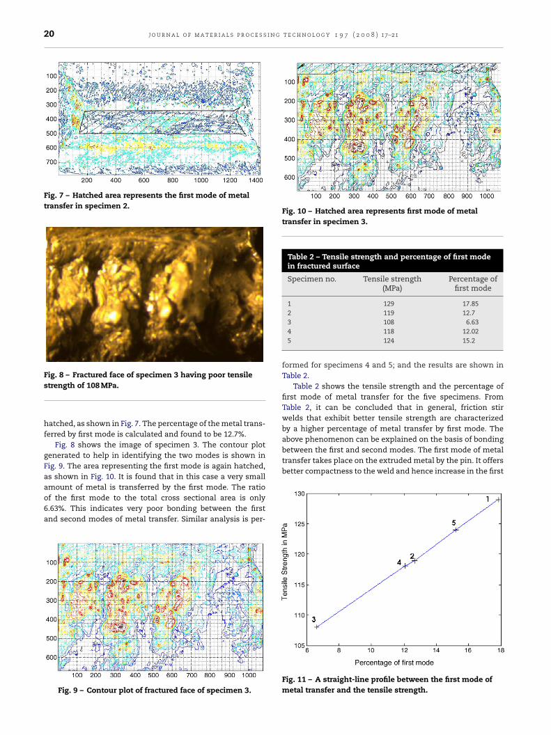
Fig. 7 – Hatched area represents the first mode of metaltransfer in specimen 2.
Fig. 8 – Fractured face of specimen 3 having poor tensile
Fig. 10 – Hatched area represents first mode of metaltransfer in specimen 3.
Table 2 – Tensile strength and percentage of first modein fractured surface
Specimen no. Tensile strength(MPa)
Percentage offirst mode
1 129 17.852 119 12.7
above phenomenon can be explained on the basis of bondingbetween the first and second modes. The first mode of metaltransfer takes place on the extruded metal by the pin. It offersbetter compactness to the weld and hence increase in the first
strength of 108 MPa.
hatched, as shown in Fig. 7. The percentage of the metal trans-ferred by first mode is calculated and found to be 12.7%.
Fig. 8 shows the image of specimen 3. The contour plotgenerated to help in identifying the two modes is shown inFig. 9. The area representing the first mode is again hatched,as shown in Fig. 10. It is found that in this case a very small
amount of metal is transferred by the first mode. The ratioof the first mode to the total cross sectional area is only6.63%. This indicates very poor bonding between the firstand second modes of metal transfer. Similar analysis is per-Fig. 9 – Contour plot of fractured face of specimen 3.
3 108 6.634 118 12.025 124 15.2
formed for specimens 4 and 5; and the results are shown inTable 2.
Table 2 shows the tensile strength and the percentage offirst mode of metal transfer for the five specimens. FromTable 2, it can be concluded that in general, friction stirwelds that exhibit better tensile strength are characterizedby a higher percentage of metal transfer by first mode. The
Fig. 11 – A straight-line profile between the first mode ofmetal transfer and the tensile strength.

g t
mtipafii
t4hhfss
rfioapas
5
Ibsdpd
1
2
3
4
r
j o u r n a l o f m a t e r i a l s p r o c e s s i n
ode is found to improve the tensile property of the weld,hereby resulting in defect free weld with better strength. Thismprovement in tensile property is explained due to the com-ressive load offered by the first mode on the metal extrudedround the pin. There exists a linear relationship between therst mode of metal transfer and the tensile strength as shown
n Fig. 11.Cavaliere et al. (2006a,b) performed FSW by employing rota-
ional speeds of 500, 800 and 1000 rpm and traverse speeds of0, 56 and 80 mm/min, respectively. They observed that theighest tensile strength is reached in correspondence of theighest rotation speed, at the highest traverse speed. However,
rom the results obtained in Table 2, it is clear that exces-ive or lesser pin length may adversely decrease the tensiletrength.
Process parameter variations, such as changes in toolotation or traverse speed, will produce different thermal pro-les (Kamp et al., 2006). The volume fraction of the bandsf new nugget scale grains rises with strain and temper-ture (Prangnell and Heason, 2005). Hence, change in therocess parameters causes changes in the weld propertiesnd the two modes of metal transfer, thereby affecting tensiletrength.
. Conclusion
n the present study, FSW of 6063 aluminium alloys haveeen carried out at different process parameters. The tensilepecimens are prepared from the welded plate as per the stan-ard and tested. The fractured faces are analysed using imagerocessing techniques and the following conclusions can berawn:
. The two modes of metal transfer are distinct in the frac-tured surfaces.
. The first mode increases the compactness of the weld andeliminates defects. Hence, an increase in the first mode ofmetal transfer improves the tensile properties.
. There exists a linear correlation between the percentage offirst mode in the fractured surface and the ultimate tensile
strength.. All the three parameters considered in the present study;tool rotation speed, traverse speed and pin length are foundto affect the first mode of metal transfer.
e c h n o l o g y 1 9 7 ( 2 0 0 8 ) 17–21 21
However, this work is a preliminary attempt to investigatethe quantity of metal transferred by the two modes and fur-ther study needs to be done to understand the influence ofthe individual process parameters on the two modes of metaltransfer.
e f e r e n c e s
Biallas, G., Braun, R., Donne, C.D., Staniek, G., Kaysser, W.A., 1999.Mechanical properties and corrosion behavior of friction stirwelds 2024-T6. First international conference on friction stirwelds. Thousand Oaks, CA.
Bussu, G., Irving, P.E., 2003. The role of residual stress and heataffected zone properties on fatigue crack propagation infriction stir welding 2024-T351 aluminium joints. Int. J.Fatigue 25, 77–88.
Cavaliere, P., Nobile, R., Panella, F., Squillace, A., 2006a.Mechanical and microstructural behaviour of 2024-7075aluminium alloy sheets joined by friction stir welding. Int. J.Mach. Tools Manuf. 46, 588–594.
Cavaliere, P., Campanile, G., Panella, F., Squillace, A., 2006b. Effectof welding parameters on mechanical and microstructuralproperties of AA6056 joints produced by friction stir welding.J. Mater. Process. Technol. 180, 263–270.
Colligan, K.J., 1999. Marerial flow behaviour during friction stirwelding of aluminium. Weld. J. 78 (7), 229–237.
Elangovan, K., Balasubramanian, V., 2007. Influences of pinprofile and rotational speed of the tool on the formation offriction stir processing zone in AA2219 aluminium alloy,Mater. Sci. Eng. A 459, 7–18.
Kamp, N., Sullivan, A., Tomasi, R., Robson, J.D., 2006. Modelling ofheterogeneous precipitate distribution evolution duringfriction stir welding process. Acta Mater. 54, 2003–2014.
Muthukumaran, S., Mukherjee, S.K., 2006. Two Modes of Metalflow phenomenon in friction stir welding process. Sci.Technol. Weld. Join. 11, 337–340.
Prangnell, P.B., Heason, C.P., 2005. Grain structure formationduring friction stir welding observed by the stop actiontechnique. Acta Mater. 53, 3179–3192.
Thomas, W.M., Needham, E.D., Murch, M.G., Temple-Smith, P.,Dawes, C.J., 1991. Friction stir butt welding, Int. PatentApplication no. PCT/GB92/02203 and GB Patent Applicationno. 9125978.8;;
Thomas, W.M., Needham, E.D., Murch, M.G., Temple-Smith, P.,
Dawes, C.J., 1995. Friction stir butt welding, US Patent no.5,460,317.Xu, S., Deng, X., Reynolds, A.P., Seidel, T.U., 2001. Finite elementsimulation of material flow in friction stir welding. Sci.Technol. Weld. Join. 6, 191–193.