Journal of Sound and Vibration - mypolyuweb.hk · ficient, measured in either a reverberation...
16
Sound absorption of microperforated panels inside compact acoustic enclosures Cheng Yang, Li Cheng n Department of Mechanical Engineering, The Hong Kong Polytechnic University, Hung Hom, Hong Kong Special Administrative Region article info Article history: Received 22 January 2015 Received in revised form 16 September 2015 Accepted 16 September 2015 Handling Editor: R.E. Musafir Available online 3 October 2015 abstract This paper investigates the sound absorption effect of microperforated panels (MPPs) in small-scale enclosures, an effort stemming from the recent interests in using MPPs for noise control in compact mechanical systems. Two typical MPP backing cavity config- urations (an empty backing cavity and a honeycomb backing structure) are studied. Although both configurations provide basically the same sound absorption curves from standard impedance tube measurements, their in situ sound absorption properties, when placed inside a small enclosure, are drastically different. This phenomenon is explained using a simple system model based on modal analyses. It is shown that the accurate prediction of the in situ sound absorption of the MPPs inside compact acoustic enclosures requires meticulous consideration of the configuration of the backing cavity and its cou- pling with the enclosure in front. The MPP structure should be treated as part of the entire system, rather than an absorption boundary characterized by the surface impedance, calculated or measured in simple acoustic environment. Considering the spatial matching between the acoustic fields across the MPP, the possibility of attenuating particular enclosure resonances by partially covering the enclosure wall with a properly designed MPP structure is also demonstrated. & 2015 Elsevier Ltd. All rights reserved. 1. Introduction Microperforated panels (MPPs) exhibit appealing features as compared with conventional fibrous sound-absorbing materials. The acoustic impedance of an MPP can be predicted by the formula proposed by Maa [1], as an extension of the short tube theory of Rayleigh and Crandall. In order to achieve effective sound absorption, an air layer is usually required to be introduced between the MPP and the backing rigid wall to generate the Helmholtz resonance effect. This typical MPP structure is usually referred to as the microperforated panel absorber (MPPA) [1]. Extensive efforts were made to improve the sound absorption of various MPP configurations, as reported in the open literature [2–12]. Earlier, the MPPs were used in architectural acoustics and for controlling environmental noise, where simple acoustic field is usually considered, either diffuse or plane wave in most cases. An MPPA, in this connection, is usually treated as a sound-absorbing material with its acoustic properties characterized by the surface impedance or sound absorption coef- ficient, measured in either a reverberation chamber or a Kundt's tube. For example, in a large room, sound-absorbing materials, when attached to the wall of an enclosure, reduce the sound reflection through energy dissipation. Assuming a Contents lists available at ScienceDirect journal homepage: www.elsevier.com/locate/jsvi Journal of Sound and Vibration http://dx.doi.org/10.1016/j.jsv.2015.09.024 0022-460X/& 2015 Elsevier Ltd. All rights reserved. n Corresponding author. E-mail address: [email protected] (L. Cheng). Journal of Sound and Vibration 360 (2016) 140–155
Transcript of Journal of Sound and Vibration - mypolyuweb.hk · ficient, measured in either a reverberation...

Contents lists available at ScienceDirect
Journal of Sound and Vibration
Journal of Sound and Vibration 360 (2016) 140–155
http://d0022-46
n CorrE-m
journal homepage: www.elsevier.com/locate/jsvi
Sound absorption of microperforated panels inside compactacoustic enclosures
Cheng Yang, Li Cheng n
Department of Mechanical Engineering, The Hong Kong Polytechnic University, Hung Hom, Hong Kong Special Administrative Region
a r t i c l e i n f o
Article history:Received 22 January 2015Received in revised form16 September 2015Accepted 16 September 2015
Handling Editor: R.E. MusafirAlthough both configurations provide basically the same sound absorption curves from
Available online 3 October 2015
x.doi.org/10.1016/j.jsv.2015.09.0240X/& 2015 Elsevier Ltd. All rights reserved.
esponding author.ail address: [email protected] (L. Cheng
a b s t r a c t
This paper investigates the sound absorption effect of microperforated panels (MPPs) insmall-scale enclosures, an effort stemming from the recent interests in using MPPs fornoise control in compact mechanical systems. Two typical MPP backing cavity config-urations (an empty backing cavity and a honeycomb backing structure) are studied.
standard impedance tube measurements, their in situ sound absorption properties, whenplaced inside a small enclosure, are drastically different. This phenomenon is explainedusing a simple system model based on modal analyses. It is shown that the accurateprediction of the in situ sound absorption of the MPPs inside compact acoustic enclosuresrequires meticulous consideration of the configuration of the backing cavity and its cou-pling with the enclosure in front. The MPP structure should be treated as part of the entiresystem, rather than an absorption boundary characterized by the surface impedance,calculated or measured in simple acoustic environment. Considering the spatial matchingbetween the acoustic fields across the MPP, the possibility of attenuating particularenclosure resonances by partially covering the enclosure wall with a properly designedMPP structure is also demonstrated.
& 2015 Elsevier Ltd. All rights reserved.
1. Introduction
Microperforated panels (MPPs) exhibit appealing features as compared with conventional fibrous sound-absorbingmaterials. The acoustic impedance of an MPP can be predicted by the formula proposed by Maa [1], as an extension of theshort tube theory of Rayleigh and Crandall. In order to achieve effective sound absorption, an air layer is usually required tobe introduced between the MPP and the backing rigid wall to generate the Helmholtz resonance effect. This typical MPPstructure is usually referred to as the microperforated panel absorber (MPPA) [1]. Extensive efforts were made to improvethe sound absorption of various MPP configurations, as reported in the open literature [2–12].
Earlier, the MPPs were used in architectural acoustics and for controlling environmental noise, where simple acousticfield is usually considered, either diffuse or plane wave in most cases. An MPPA, in this connection, is usually treated as asound-absorbing material with its acoustic properties characterized by the surface impedance or sound absorption coef-ficient, measured in either a reverberation chamber or a Kundt's tube. For example, in a large room, sound-absorbingmaterials, when attached to the wall of an enclosure, reduce the sound reflection through energy dissipation. Assuming a
).

C. Yang, L. Cheng / Journal of Sound and Vibration 360 (2016) 140–155 141
sufficiently high modal density of the enclosure, the acoustic field may be considered as diffuse and the enclosureboundaries, where the sound-absorbing materials are placed, could be treated as locally reactive, showing that the responseat one point is independent of the response at any other point [13,14], which applies for most music halls and industrialrooms within the audio frequency range. This treatment is generally well accepted, although some experimental workshowed that the acoustic field inside a reverberation room with a flexible wall on the boundary cannot be correctly esti-mated in terms of the locally reactive normal acoustic impedance in the low-frequency range [15].
The unique physical property of MPPAs also shows a great potential for noise control in complex mechanical systemssuch as magnetic resonance imaging (MRI) scanners [16], cooling systems [17], nacelles of turbofan engines [18], andinteriors of engine enclosures [19]. A common feature of these problems is that the MPPA may closely interact with thesurrounding vibroacoustic elements, thus creating problems that are not encountered by typical architectural and envir-onmental acoustics. This calls for revisiting and interrogating the in situ sound absorption mechanism of the MPPA undermore complex vibroacoustic working environment by considering its interaction with the surrounding acoustic media.
The complex vibroacoustic behaviors of the MPPA also attracted the attention of researchers. One example is theobservation of unexpected peaks in the sound absorption curve attributed to the structural resonance of the MPP. In order toconsider this effect, the MPP vibration was introduced into the equivalent circuit model, leading to improved predictionaccuracy [20]. Simultaneously, modal expansion methods were also used to investigate the vibroacoustic behaviors of theMPPA [21,22], shedding light on the structural effect of MPPs on the absorption performance. In addition to the structuralvibration, the sound absorption behavior is also dependent on the acoustic field inside the MPPA backing cavity. Forexample, appreciable changes were observed in the sound absorption curve when the wall of the backing cavity is slightlytilted [23]. In addition to the vibroacoustic property of the MPPA itself, the acoustic field in front also affects the soundabsorption performance. For example, a previous work [24] demonstrated that when an MPPA is subjected to an obliqueplane wave, it behaves differently at different incident angles, because of the dominant contribution of different types ofacoustic modes to the backing cavity acoustic field.
Despite the progressive efforts made in the past, the in situ sound absorption behavior of MPPAs in a strongly coupledvibroacoustic system has never been systematically documented in the literature, to the best of the authors' knowledge.More importantly, the influence of the surrounding acoustic fields on the MPP, the extent to which they affect the energydissipation inside the MPP pores, and the possibility of designing a suitable MPPA to suppress particular system resonancesare the important areas to be explored. As a continuation of the previous work [24], this study investigates the afore-mentioned issues by emphasizing the application of MPPs in compact acoustic enclosures. By virtue of the remoteness ofacoustic modes in the frequency domain, the acoustic fields of the so-called compact enclosures exhibit distinguishablemodal features, and the absorption boundary corresponding to MPPAs may have strong interactions with the enclosure. Thisstudy also underscores the importance of considering MPPA as part of the entire acoustic system rather than as anabsorption boundary characterized by the locally reactive impedance. As part of an acoustic system, the performance of theMPPA would be strongly influenced by the surrounding acoustic media to which it is coupled.
This article is organized as follows: Section 2 reviews the development of the acoustic impedance of the MPPA. In Section3, a fully coupled model for an MPPA coupled with an enclosure is established using modal expansion method. In Section 4,an experiment is conducted to show the in situ sound absorption of MPPAs with two different backing cavity configurations,one with an empty backing cavity and the other with a honeycomb backing structure, inside a rectangular enclosure. Theunderlying physics, observed in the experiment, is numerically studied and experimentally validated in Section 5. Thepartial coverage of MPPA on the cavity wall is then investigated, demonstrating the possibility of designing an MPPA backingcavity as well as its location to cope with particular cavity resonances.
2. Locally reactive impedance formula
Maa's locally reactive model is briefed first for the sake of completeness. Fig. 1 depicts an MPPA subjected to normalplane wave incidence, which consists of an MPP and a rigid wall, separated by an air layer of depth D.
Fig. 1. A typical locally reactive model for the MPP construction. The backing wall (bottom line) of the air layer is rigid.

C. Yang, L. Cheng / Journal of Sound and Vibration 360 (2016) 140–155142
If the separation between the pores is large enough compared with the pore diameters, the acoustic impedance of thepanel, ZMPP, can be approximated as the quotient of acoustic impedance of the individual pore and the perforation ratio(ratio of areas of pores to panel) [1].
For plane wave, the relationship between the acoustic impedances of the two boundaries of the air layer is given by [25]
Z 0ð Þ ¼ Z Dð Þþ jρc tan ðkDÞ1þ j
ρc tan ðkDÞZðDÞ; (1)
where ρ and c are the air density and sound speed, respectively. k¼ω=c is the wavenumber, with ω being the angularfrequency. With a rigid backing wall, the acoustic impedance (or the reactance, because this term is purely imaginary) at thetop of the air layer becomes
Z 0ð Þ ¼ ZCav ¼ � jρc cot kDð Þ: (2)
According to the equivalent electro-acoustic approach, the acoustic impedances of the MPP and the backing air layer arearranged in series. Therefore, the total acoustic impedance of the MPPA is
ZMPPA ¼ ZMPPþZCav ¼ ZMPP� jρc cot kDð Þ: (3)
Eq. (3) suggests that the air mass inside the pores vibrates independently in the x direction, which is normal to the panelsurface, and the reactance offered by the air layer is uniform across the MPP surface. Therefore, the MPPA modeled in thismanner is locally reactive. Fig. 2 depicts the magnitude of the imaginary part of ZMPPA, in terms of its two components: ZMPP
and Zcav. It can be seen that, once the reactance of ZMPP intersects with the negative part of the reactance of the backing airlayer (solid line), a sound absorption peak appears (circle). At these frequencies, the total reactance vanishes and the MPPAworks as a Helmholtz resonator at its resonant frequencies. However, the frequencies at which the reactance magnitude ofthe backing air layer is extremely large correspond to the absorption dips (triangle). Between each pair of peak and dip,where the variation of the reactance of the backing air layer is moderate, good sound absorption is obtained. The reactancemagnitude of the backing cavity is quite large at low frequencies, restricting the use of MPPA in low-frequency noise unless alarge cavity depth D is deployed. Recent studies [26,27] attempt to overcome this problem using active control techniques toreduce larger reactance of the backing air layer, yielding higher sound absorption coefficient in the low-frequency range.
Maa also developed a model for the oblique incidence case, in which the reactance provided by the backing air layer is afunction of the wave incidence angle and is dependent on the path difference between the incident and reflected waves.However, that model could not be directly used as an impedance boundary in an enclosure unless a prior knowledge on theincidence angle at each frequency is available. Up to now, it has only been used to calculate the absorption coefficient indiffuse field for architectural acoustic problems to which the sound decay rate of an enclosure is related. It is also worthnoting that, when the backing air layer is laterally bounded and has a finite lateral size, the whole assembly becomesnonlocally reactive [28]. In that case, the locally reactive model cannot fully describe the acoustic behavior of the MPPA.
Fig. 2. (a) Magnitude of the reactance of the MPP construction. Negative Zcav, —; positive Zcav, —; ZMPP, . (b) Corresponding sound absorption curve ofthe MPPA.

C. Yang, L. Cheng / Journal of Sound and Vibration 360 (2016) 140–155 143
3. A fully coupled enclosure – MPPA model
A model for an acoustic enclosure coupled with an MPPA is developed based on classical modal method, which has beenwidely used to study the vibroacoustic coupling problems in different configurations [29–31]. Assuming that the MPPA isnonlocally reactive, the acoustic field in the backing cavity is modeled as part of the system.
Fig. 3 shows an enclosure having an MPPA flush-mounted on one of its walls. Note that the MPP coverage can be eitherfull or partial over the enclosure wall. The enclosure (domain 1) has physical boundaries comprising acoustically rigid wallsand the MPP, excited by an acoustic point source, Q(rs). The backing cavity of the MPPA is modeled as another acousticdomain (domain 2).
Once activated, the motion of air inside the MPP pores becomes a secondary source, radiating sound into domains 1 and2 simultaneously. In a harmonic regime, the acoustic pressure field in domain 1 can be described by the Kirchhoff–Helmholtz integral equation as [32]
p1 ¼ � jρωZSaG1v1 dSaþ
ZVs
G1Q dVs; (4)
where G1 is the Green's function for domain 1, v1 is the averaged normal air particle velocity over the MPP surface Sa(positive outward), and Q(rs)¼ jρωqδ(r�rs), with q being the volume velocity of source and δ(r) the Dirac delta function.
Eq. (4) indicates that the overall acoustic pressure field in domain 1 is composed of two parts: (1) boundary radiation dueto the normal velocity of the MPP surface and (2) boundary radiation by the point source with all boundaries beingacoustically rigid.
The acoustic field in domain 2 is only determined by the velocity of the MPP surface, which can be expressed as
p2 ¼ � jρωZSaG2v2 dSa: (5)
The motion of the air particle over the MPP surface is a result of the pressure difference across its surface, described as
v1 ¼p1�p2ZMPP
: (6)
Given a very thin MPP, the velocity of the air particles is assumed to have the same magnitude across the pores:
v1 ¼ �v2: (7)
The structural vibration of panel is ignored for simplicity.The acoustic pressure in domains 1 and 2 are expanded in terms of their respective rigid-walled cavity modes, ϕm and ψn
as
p1 ¼Xm
Amϕm (8)
p2 ¼Xn
Bnψn: (9)
Meanwhile, Green's function in each cavity, which satisfies the Neumann boundary condition, can also be obtained bynormal modal expansion in terms of its rigid-walled modes as
G1ðr; r0Þ ¼Xm
ϕmðrÞϕmðr0ÞΛ1mðk21m�k2Þ
(10)
Fig. 3. MPPA coupled to the enclosure.

C. Yang, L. Cheng / Journal of Sound and Vibration 360 (2016) 140–155144
G2 r; r0ð Þ ¼Xn
ψn rð Þψn r0ð ÞΛ2n k22n�k2
� �; (11)
with the modal mass terms defined as
Λ1m ¼ZV1
ϕ2mðrÞdV (12)
Λ2n ¼ZV2
ψ2nðrÞdV ; (13)
where k1m and k2n are the wavenumbers for the modes m and n in domains 1 and 2, respectively.Green's functions are then introduced into Eqs. (4) and (5) to calculate the acoustic pressure of each domain. Applying
the boundary conditions, Eqs. (6) and (7) yield
p1 ¼ � jρωZSaG1
p1�p2ZMPP
dSaþZVs
G1Q dVs (14)
p2 ¼ � jρωZSaG2
p2�p1ZMPP
dSa: (15)
Fig. 4. Experimental setup: (a) enclosure; (b) MPPA having an empty air cavity; and (c) MPPA having a honeycomb structure inside the backing cavity.

C. Yang, L. Cheng / Journal of Sound and Vibration 360 (2016) 140–155 145
Then, substituting Eqs. (8)–(13) into Eqs. (14) and (15) and using the orthogonal property, one obtains
k21m�k2� �
Λ1mAmþ jkCMPP
Xm0L
1ð Þm;m0Am0 � jkCMPP
Xn
Rm;nBn ¼ jρckqϕm rsð Þ (16)
k22n�k2� �
Λ2nBnþ jkCMPP
Xn0L 2ð Þn;n0Bn0 � jkCMPP
Xm
Rm;nAm ¼ 0; (17)
where CMPP¼ρc/ZMPP is the specific acoustic admittance of the MPP.Obviously, the cavity modes of the original enclosure are modified by the MPPA, the influence of which is manifested as
the specific acoustic modal admittance of the MPP weighted by the auto- and cross-modal coupling coefficients defined as
Lð1Þm;m0 ¼ZSaϕmϕm0 dSa (18)
Lð2Þn;n0 ¼ZSaψnψn0 dSa (19)
Rm;n ¼ZSaϕmψn dSa: (20)
In total, there are three groups of modal coupling coefficient in the above definitions. The first two apply to each domainand are the results of the MPP serving as an impedance boundary. The last one describes the modal interaction between thetwo acoustic domains, as a result of the velocity continuity between the two sides of the MPP, analogous to the connectionof two acoustic cavities with a virtual panel as the interface [25], through which the backing cavity is coupled with theenclosure.
The coupled system formulated in Eqs. (16) and (17) can be written as a (MþN) matrix equation, where M and N are thenumber of modes of the enclosure and that of the MPPA backing cavity under consideration, respectively. It can be solved bystandard method upon a proper modal truncation. In addition, the model takes into account the acoustic coupling betweenthe two domains (1 and 2) through the modal coupling coefficients defined in Eq. (20). This feature essentially results in thedifference between the locally reactive model and the proposed model, to be demonstrated in the following sections.
4. Experimental observations
First, a right parallelepiped enclosure, shown in Fig. 4(a), was tested experimentally. The enclosure was fabricated using a30-mm-thick acrylic panel. The inner dimensions of the enclosure are listed in Table 1.
Two MPPAs with different backing configurations were studied: one has an entire air volume and the other has ahoneycomb structure at the back of the MPP. The former, shown in Fig. 4(b), was installed on the enclosure by replacing theoriginal wall of the enclosure at y¼0.63 m. Parameters of the MPP and the dimensions of the backing cavity are alsotabulated in Table 1. For the latter, the backing honeycomb structure is shown in Fig. 4(a) and (c).
In the experiment, a loudspeaker was used to excite the enclosure. The loudspeaker was mounted outside the cavity wall,feeding acoustic excitation to the enclosure through an acrylic cone at (0.06, 0, 0.06). The acoustic excitation strength isquantified using the transfer function between the two Brüel & Kjær 4942½″ microphones, located at (0.291, 0.547, 0.175)and (0.06, 0.015, 0.06), respectively. The location of the first microphone (observation) was randomly selected, and thesecond microphone (reference) was placed very close to the apex of the cone. The transfer function (TF) between the twomicrophones is defined as
TF¼ 20log10pmic1
pmic2: (21)
4.1. Enclosure without MPPA
Validation of the experimental model was first performed before mounting the MPPA to provide a benchmark for furtherevaluations. The predicted and measured TFs are compared in Fig. 5. In the simulation, a loss factor of 0.001 is used. As the
Table 1Dimensions and parameters of the enclosure and MPPA used in the experimental investigation.
Enclosure MPPA
Lx Ly Lz D Pore diameter Panel thickness Perforation
0.38 m 0.63 m 0.51 m 0.05 m 0.35 mm 0.35 mm 1%

Fig. 5. Transfer functions (TFs) for the enclosure without MPPA.
Fig. 6. Measured transfer functions (TFs) for the enclosure without MPPA, with MPPA having an empty backing cavity, with MPPA having honeycombstructure inside the backing cavity.
C. Yang, L. Cheng / Journal of Sound and Vibration 360 (2016) 140–155146
result shows, a frequency shift is found at a very low frequency of around 50 Hz, which may be caused by the opening thatholds the cone apex [33]. Discrepancies at higher frequencies are possibly due to the acoustic scattering on the surfaces ofcables and microphones. In general, the proposed model agrees well with the experimental results. The loss factor used inthe simulation seems to be an adequate estimation of the system damping. Thus, the platform offers a convincing baselinefor further investigations.
4.2. Sound absorption effect of the MPPAs
The in situ sound absorption of the two MPPAs is investigated. The measured TFs (Eq. (21)), corresponding to threedifferent configurations (without MPPA, with MPPA having an empty backing cavity, and with MPPA having a honeycomb-filled backing cavity), are plotted and compared in Fig. 6. As a reference, the sound absorption coefficient curves of the twoMPPAs measured from the impedance tube tests are also given in Fig. 7. It can be seen that, although the two MPPAs presentvery similar sound absorption curves (Fig. 7), their in situ sound absorption performances, as shown in Fig. 6, are quitedifferent. This difference can be observed over a broad frequency band. In addition to the obvious superiority of the hon-eycomb backing configuration over the empty one, a closer examination reveals the deficiency of the latter. More specifi-cally, in the frequency range where high sound absorption is expected from the impedance tube test (500–1200 Hz), theMPPA with an empty backing cavity fails to render the expected noise reduction at many dominant frequencies. Thesephenomena will be thoroughly investigated in the following sections.

Fig. 7. Sound absorption coefficients measured from impedance tube test and predicted by Maa's theoretical model. In the test, MPP is placed in front ofthe air layer and the honeycomb, respectively.
Table 2Dimensions and parameters of the enclosure and MPPA used in numerical analysis. (following the schematic in Fig. 3).
Enclosure MPPA
Lx Ly D Pore diameter Panel thickness Perforation
1 m 0.4 m 0.05 m 0.2 mm 0.2 mm 1%
C. Yang, L. Cheng / Journal of Sound and Vibration 360 (2016) 140–155 147
5. Analyses
5.1. MPPA with an entire air volume at the back
In order to explain the aforementioned phenomena, an MPPAwith an entire empty air volume at the back is investigatedfirst. Numerical analyses are carried out in two-dimensional space perpendicular to the MPP surface for convenience.Parameters of the enclosure and the MPPA are listed in Table 2. A point source having a unit volume velocity is assumedaround the corner at (0.03, 0.03).
For analyses, a space-averaged quadratic sound pressure inside the enclosure is defined as [34]
p1p�1
� �¼ 1=V1
Xm
Am�� ��2 Λ1m: (22)
The enclosure–MPPA coupled model is used for the analyses. In parallel, the model based on standard boundary integralmethod that treats the MPPA as an impedance boundary is also used for comparison. In the latter case, the effect of theMPPA backing cavity is embedded in the impedance formula, so that the modal interaction between the domains 1 and 2 isomitted and the coupled Eqs. (16) and (17) retreat to one equation as follows:
k21m�k2� �
Λ1mAmþ jkCMPPA
Xm0L
1ð Þm;m0Am0 ¼ jρckqϕm rsð Þ; (23)
where CMPPA¼ρc/ZMPPA is the specific acoustic admittance of MPPA with ZMPPA defined in Eq. (3). This model is referred to asthe locally reactive model as opposed to the fully coupled model described in Section 3.
Fig. 8 shows the plot of the space-averaged quadratic sound pressures against frequency for three cases: enclosurewithout MPPA (with all acoustically rigid boundaries), enclosure with MPPA with locally reactive model, and enclosure withMPPA with fully coupled model. It can be seen that the locally reactive model predicts a broadband sound absorption withfrequency ranging roughly from 300 to 1600 Hz, in agreement with the sound absorption coefficient curve obtained inimpedance tube (not shown). Almost all the resonances of the rigid-walled cavity are damped due to the modal dampingintroduced by the MPPA. Besides, frequency shifts are observed at certain peaks attributed to the reactance term of theboundary impedance. However, for its counterpart, that is, the fully coupled model, MPPA fails to suppress several reso-nances as denoted by arrows in the figure, in agreement with the experimental observations reported in Section 4.2. Thesepeaks are neither damped nor shifted, and have approximately the same magnitudes as those for the enclosure withoutMPPA. Obviously, the locally reactive model overestimates the sound absorption effect of the MPPA with an empty backingcavity.

Fig. 8. Space-averaged quadratic pressure for the enclosure without and with MPPA. The arrows indicate the undamped resonances.
Fig. 9. Real and imaginary parts of the system generalized eigenvalues. The arrows indicate the eigenvalues with zero imaginary parts.
C. Yang, L. Cheng / Journal of Sound and Vibration 360 (2016) 140–155148
In the fully coupled model, MPP couples the enclosure and the MPPA backing cavity by its surface, through which theoriginal modes of the rigid-walled enclosure are modified. The extent to which this modification occurs is quantified bymeasuring the wave matching between the modes in the two subsystems [35]. At this point, it is worthwhile to study themodal property of the coupled system to provide a physical explanation for the aforementioned phenomena. Following aniterative calculation scheme, the first few eigenvalues corresponding to the modes of the coupled system (enclosur-eþMPPþbacking cavity), normalized by c/(2Lx), are plotted in Fig. 9. These modes are termed as new modes in order todistinguish them from the original modes of the uncoupled systems. Each eigenvalue is a complex number, whose real andimaginary parts are associated with the generalized natural frequency and the loss factor of a new mode, respectively. Fig. 9shows two distinct groups of new modes: one has eigenvalues with appreciable imaginary parts and the other with neg-ligible imaginary parts. The former group corresponds to the damped new modes because of the energy dissipation of theMPP, whereas the latter group corresponds to the undamped new modes. More specifically, the real parts of thoseundamped new modes are all integers (1–5 in Fig. 9), having the same resonant frequencies as those of the lateral modes(vibrating in the direction parallel to the MPP) of the uncoupled enclosure.
Upon solving the eigenvalues of the coupled system, eigenvectors are obtained. The components of each eigenvectorquantify the contributions of the modes of the subsystems in constructing the corresponding new mode. As an example, themagnitudes of the normalized modal coefficients, which contribute to the fourth undamped newmode, are plotted in Fig. 10(a). It shows that this new mode is predominantly and equally contributed by two lateral modes: the (4, 0) mode ofenclosure and the (4, 0) mode of the MPPA backing cavity, each of which describes the acoustic pressure distribution of thenew mode in the corresponding domain (Note that (X, 0) modes involve acoustic pressure variations along the MPP sur-face.). Further examination shows that the two dominant modes also have the same phase (not shown). The in-phasevibration of the two dominant modes with identical modal amplitudes, arising from the strong coupling due to the perfect

Enclosure (4,0) MPPA backing
cavity (4,0)
Enclosure (0,1)
Enclosure (0,2)
Enclosure (0,3)
MPPA backing cavity (0,0)
MPPA backing cavity (0,1)
Fig. 10. Normalized modal coefficients (eigenvector) for the corresponding generalized eigenvalue: (a) 4þ0j (undamped new mode); and (b) 4.4þ0.3j(damped new mode).
C. Yang, L. Cheng / Journal of Sound and Vibration 360 (2016) 140–155 149
wave matching of the dominating modes with the same resonant frequencies, yields zero pressure difference across theMPP. Thus, there is no air motion inside the MPP pores, and no energy can possibly be dissipated. In such circumstances, theMPP is analogous to a rigid panel. Recalling the result in Fig. 8, these undamped resonances correspond to the resonantfrequencies of the rigid-walled modes of the uncoupled enclosure indexed by (1, 0)–(9, 0).
The analyses described above provide an explanation to the ineffectiveness of the MPPA at some resonances (Fig. 8). Thephenomenon is attributed to the geometric similarity between the enclosure and the MPPA backing cavity in the x directionthat holds the same lateral modes. If the new modes are mainly dominated by the depth modes (vibrate in the directionperpendicular to the MPP) of the subsystems, MPP may be activated. As an example, the magnitudes of the normalizedmodal coefficients of the contributing modes for a damped new mode (with a generalized eigenvalue 4.4þ0.3j) are plottedin Fig. 10(b). Obviously, the modal behavior is mainly attributed to the depth modes and the volume mode, leading to aconsiderable loss factor.
In the locally reactive impedance formula for the MPP with a backing layer, the acoustic wave is assumed to only pro-pagate in the direction normal to the MPP surface. Upon this assumption, the standing wave modes formed between thelateral boundaries of a finitely bounded MPPA are disregarded, and only the depth modes of the backing cavity are con-sidered. As a comparison, the generalized eigenvalues for the enclosure with the MPPA modeled as locally reactive impe-dance boundary are also solved and plotted (Fig. 9). It can be seen that the model predicts cross-border modal dampingfactors for almost all modes, thus resulting in an overestimation of the sound attenuation within the enclosure, in agree-ment with the observations from Fig. 8.
The involvement of the lateral modes in constructing the acoustic field of the backing cavity also depends on the natureof the acoustic media to which the MPPA is coupled. For instance, the lateral modes cannot be activated when an MPPA issubjected to a normal plane wave incidence, because of the mismatching of the waves on the two sides of the MPP. In otherwords, if the acoustic pressure loading on the MPPA surface is uniform across the MPP surface, for example, plane wave

Fig. 11. Transfer functions (TFs) for the enclosure coupled with a MPPA having an empty backing cavity.
(0,0,1)
(1,0,0)
(1,0,1)
(0,0,2)
(1,0,2) (0,0,3) (1,0,3)
Fig. 12. Measured transfer functions (TFs) for the enclosure without and with MPPA.
C. Yang, L. Cheng / Journal of Sound and Vibration 360 (2016) 140–155150
incidence in impedance tube, only the depth modes of the backing cavity would be activated. Therefore, locally reactivemodel could be used only in the absence of lateral modes. Otherwise, as both numerically and experimentally observed,locally reactive model based on impedance tube measurement cannot truthfully reflect the in situ sound absorption cap-ability of the MPPA in a compact vibroacoustic environment. A fully coupled model becomes indispensable in that case.
In order to further consolidate the above analyses, the predicted and measured TFs are compared in Fig. 11 using thethree-dimensional configuration presented in Section 4, showing a good agreement between the two curves. This confirmsthat the acoustic field in the backing air cavity has to be carefully addressed and the proposed coupled model is reliable toachieve a fairly accurate prediction. In addition, the possible structural vibration of the MPP seems to have no significantinfluence on the acoustic field in the experiment. Despite the exclusion of the panel vibration from the proposed model, it isstill acceptably accurate. Then, the measured TFs in the enclosure with and without MPPA are compared in Fig. 12, to furtherconfirm the existence of the lateral modes in the MPPA backing cavity and their effective roles in the sound absorptionperformance. As marked in the figure, some resonances are unchanged after installing the MPPA. According to the modalindices listed in the figure, these resonances are associated with the lateral modes of the enclosure, in agreement with theaforementioned observations and conclusions.
5.2. MPPA with honeycomb structure at the back
In practice, an MPPA usually has a shallow backing cavity for space-saving purpose. Consequently, the resonant fre-quencies of the lateral modes may easily fall within the frequency range of interest. One way to avoid the formation of thelateral modes is to fill up the backing cavity with a honeycomb core, by which the cut-off frequency of the original backingcavity is greatly increased. Below the cut-off frequency, the acoustic wave inside each honeycomb cell is planar and can be

C. Yang, L. Cheng / Journal of Sound and Vibration 360 (2016) 140–155 151
considered as propagating in the direction normal to the MPP surface only. Meanwhile, the honeycomb structure also helpsin enhancing the strength of the MPPA.
The previously proposed fully coupled model can be revised to model such a honeycomb-backed MPPA.Following the major steps in Section 3, when a honeycomb structure is placed within the backing cavity, the original air
volume is partitioned into a series of small subcavities corresponding to honeycomb cells. For the ith honeycomb cell, itsacoustic field can be expressed as
pi ¼ � jρωZSiGiv2ðriÞdSi; (24)
where Si and Gi are the cross-sectional area and the Green's function of the ith honeycomb cell, and v2ðriÞ is the normalvelocity on MPP surface in front of the ith honeycomb cell.
The acoustic pressure in domain 1 can be expressed by the sum of the total acoustic radiation by each cell as follows:
p1 ¼ � jρωXi
ZSiG1v1 rið ÞdSiþ
ZVs
G1Q dVs: (25)
Expanding the acoustic pressure of the ith honeycomb cell yields
pi ¼Xn
Bn;iψn: (26)
The equations describing the enclosure coupled with the MPPA containing the honeycomb-backing structure thenbecome
k21m�k2� �
Λ1mAmþ jkCMPP
Xi
Xm'L
1;ið Þm;m0Am0 �
Xn
RðiÞm;nBn;i
!¼ jρckqϕm rsð Þ (27)
k22n�k2� �
Λ2nBn;iþ jkCMPPP
n0 Lið Þn;n0Bn0 ;i� jkCMPP
Xm
R ið Þm;nAm ¼ 0 for the ith honeycomb cell; (28)
where the modal coupling coefficients are
L 1;ið Þm;m0 ¼
ZSiϕmϕm0dSi (29)
LðiÞn;n0 ¼ZSiψnψn0dSi (30)
RðiÞm;n ¼
ZSiϕmψndSi: (31)
Eqs. (27) and (28) can be written in the form of a (MþN� I) matrix form, where I is the number of honeycomb cells.Fig. 13 compares the measured and predicted TFs. Predictions are made using the model described above and the locally
reactive model formulated by Eq. (23). The agreement between the experimental and numerical results using both modelsseems to be very satisfactory. Most importantly, both models also agree well with each other. This is understandable,because with a honeycomb structure, the acoustic field in each backing cell is not directly coupled, but indirectly through
Fig. 13. Transfer functions (TFs) for the enclosure coupled with a MPPA having honeycomb structure inside the backing cavity.

C. Yang, L. Cheng / Journal of Sound and Vibration 360 (2016) 140–155152
the enclosure. Given that the dimensions of the cells are small, this indirect coupling is rather weak so that the MPPAbehaves mainly in a locally reactive manner. In this case, an MPPA could be treated roughly as an impedance boundary usingits locally reactive normal acoustic impedance. This simplification greatly reduces the computation time compared with thefully coupled model. However, it is important to note that such simplification holds only when the cross-sectional area ofthe honeycomb cells is comparably smaller than the wavelength of interest so that the contributions of the lateral modesinside the cells are negligible, the rule of thumb being less than a quarter of the smallest wavelength [36]. Otherwise, lateralmodes should be considered, requiring the use of the coupled model presented in this article.
5.3. Enclosure partially covered by MPPA
The analyses described above consider full MPPA coverage on one of the enclosure walls, giving rise to the same lateralmodes because of the geometric similarity between the two cavities. As shown both numerically and experimentally, anMPPA containing an entire backing volume shows deficiencies because of the perfect wave matching at the resonant fre-quencies of the lateral modes. Meanwhile, this may also suggest the possibility of using MPPA backing cavity, particularly itscoupling with the front acoustic field, to cope with particular enclosure resonances. This issue is examined by investigatingpartial MPPA coverage with varying locations on the enclosure wall.
The system shown in Fig. 3 is considered again, with an entire air volume-backed MPPA, flush-mounted partially on thetop wall of the enclosure from (W, 0.4) to (Wþ0.28, 0.4), where the width of the MPPA is fixed at an arbitrarily chosen valueof 0.28 m. The value of W varies, thereby changing the MPPA location. The observed dimensions of the enclosure, the depthof the air gap behind the MPP, and the parameters of the MPP are similar to those listed in Table 2. Without loss ofgenerality, a resonance at 1548 Hz corresponding to the (9, 0) mode of the enclosure is arbitrarily chosen as the targetedfrequency to be controlled. The width of the MPPA is chosen in such a way that the resonant frequency of the targetedenclosure mode falls within the interval between the resonant frequencies of the (2, 0) and (3, 0) modes of MPPA backingcavity.
The space-averaged quadratic sound pressure inside the enclosure with and without MPPA is depicted in Fig. 14. Forcomparison, the result for the MPPA with honeycomb backing cavity of the same size at the same position (W¼0.18 m) isalso provided. It can be seen that, in this particular case, the MPPA with an empty backing cavity outperforms the one withhoneycomb in suppressing the targeted resonance peak. The control effect, however, largely depends on the location of theMPPA (see the curve with W¼0.36 m). In order to explain this phenomenon, eigenvalue analyses similar to that performedin Section 5.1 is conducted. The equivalent modal damping brought about by the MPPA to a particular enclosure mode canbe described by the loss factor quantified by the imaginary part of the generalized eigenvalues of the coupled system. Fig. 15shows the plot of the effective loss factor against the location of the MPPA W. Indeed, W¼0.18 m corresponds to themaximum loss factor, resulting in a significant reduction of the resonance peak shown in Fig. 14. On the contrary, the lossfactor reaches minimum when W¼0.36 m, corresponding to a slightly damped resonance peak in Fig. 14.
The location-dependent damping effect of MPPA is further explored by examining the spatial coupling between theacoustic fields across the MPP. Using Eq. (16), the free vibration equation for themth mode of the enclosure coupled with theMPPA, after suppressing the source term on the right-hand side of the equation, can be written as
k21m�k2� �
þ jkCMPP
Xm0
L 1ð Þm;m0Am0
Λ1mAm� jkCMPP
Xn
Rm;nBn
Λ1mAm¼ 0: (32)
Fig. 14. Space-averaged quadratic pressure for the enclosure without MPPA and partially covered by MPPA.
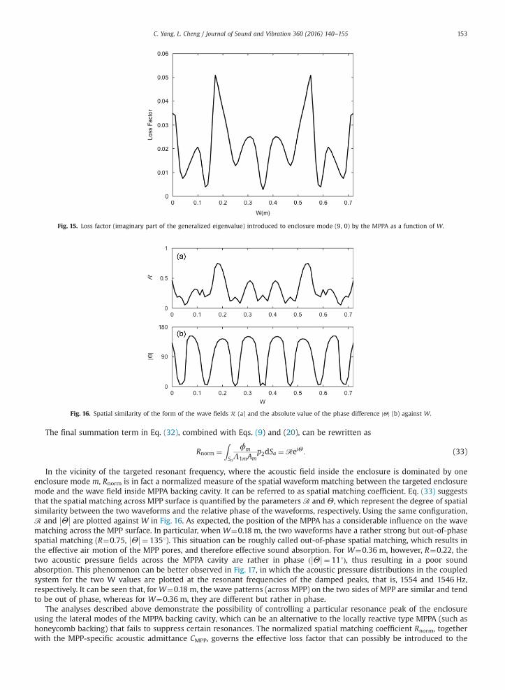
Fig. 15. Loss factor (imaginary part of the generalized eigenvalue) introduced to enclosure mode (9, 0) by the MPPA as a function of W.
Fig. 16. Spatial similarity of the form of the wave fields R (a) and the absolute value of the phase difference Θjj (b) against W.
C. Yang, L. Cheng / Journal of Sound and Vibration 360 (2016) 140–155 153
The final summation term in Eq. (32), combined with Eqs. (9) and (20), can be rewritten as
Rnorm ¼ZSa
ϕm
Λ1mAmp2dSa ¼ℛeiΘ: (33)
In the vicinity of the targeted resonant frequency, where the acoustic field inside the enclosure is dominated by oneenclosure mode m, Rnorm is in fact a normalized measure of the spatial waveform matching between the targeted enclosuremode and the wave field inside MPPA backing cavity. It can be referred to as spatial matching coefficient. Eq. (33) suggeststhat the spatial matching across MPP surface is quantified by the parameters ℛ andΘ, which represent the degree of spatialsimilarity between the two waveforms and the relative phase of the waveforms, respectively. Using the same configuration,ℛ and Θ
�� �� are plotted against W in Fig. 16. As expected, the position of the MPPA has a considerable influence on the wavematching across the MPP surface. In particular, when W¼0.18 m, the two waveforms have a rather strong but out-of-phasespatial matching (R¼0.75, Θ
�� ��¼ 1351). This situation can be roughly called out-of-phase spatial matching, which results inthe effective air motion of the MPP pores, and therefore effective sound absorption. For W¼0.36 m, however, R¼0.22, thetwo acoustic pressure fields across the MPPA cavity are rather in phase ð Θ
�� ��¼ 111Þ, thus resulting in a poor soundabsorption. This phenomenon can be better observed in Fig. 17, in which the acoustic pressure distributions in the coupledsystem for the two W values are plotted at the resonant frequencies of the damped peaks, that is, 1554 and 1546 Hz,respectively. It can be seen that, forW¼0.18 m, the wave patterns (across MPP) on the two sides of MPP are similar and tendto be out of phase, whereas for W¼0.36 m, they are different but rather in phase.
The analyses described above demonstrate the possibility of controlling a particular resonance peak of the enclosureusing the lateral modes of the MPPA backing cavity, which can be an alternative to the locally reactive type MPPA (such ashoneycomb backing) that fails to suppress certain resonances. The normalized spatial matching coefficient Rnorm, togetherwith the MPP-specific acoustic admittance CMPP, governs the effective loss factor that can possibly be introduced to the

Fig. 17. Sound pressure distribution at the resonant frequency of the damped peak: (a) W¼0.18 m and (b) W¼0.36 m. The sound pressure field is nor-malized for better visualization.
C. Yang, L. Cheng / Journal of Sound and Vibration 360 (2016) 140–155154
targeted mode of the enclosure. The former depends on the location and geometry of the MPPA and the latter is controlledby the physical property of the MPP. Thus, for constructing an effective design of an MPPA containing an entire backingcavity, an out-of-phase wave matching with suitable frequency properties of the MPP should be considered.
6. Conclusions
The in situ sound absorption properties of MPPAs with two backing configurations are investigated in this paper: onecontains an entire air volume and the other has a honeycomb structure at the back. Although the standard impedance tubemeasurements predict very similar sound absorption coefficient curves, they in fact exhibit drastically different in situ soundabsorption behaviors when placed inside a compact acoustic enclosure. For the former configuration, an effective couplingbetween the backing cavity and the enclosure arises via lateral modes, which weakens or even neutralizes the energydissipation capacity of the MPP. As a result, broadband sound absorption derived from the impedance tube measurementcould not be materialized. Numerical and experimental studies show that an MPPA should be considered as part of theentire acoustic system rather than being treated as a locally reactive absorption boundary. The inner partitions of thehoneycomb backing structure destroy the lateral modes formed in the backing cavity, thus yielding a local response of theMPPA to the acoustic loading upon its surface. This leads to superior in situ sound absorption inside the enclosure when oneenclosure wall is fully covered by an MPPA. When partially covered, the backing cavity of the MPPA as well as its location canbe designed to cope with a particular cavity resonance. A properly designed MPPAwith suitable frequency properties shouldbe placed on the enclosure wall in such a way that an out-of-phase spatial waveform matching between the two acousticfields is generated, leading to a maximum pressure difference across the MPP panel. In this case, optimal use of the effect ofthe lateral modes of the MPPA backing cavity can be obtained, which outperforms its honeycomb counterpart in attenuatingparticular enclosure resonances.
In conclusion, this study shows that an effective design and an accurate prediction of the in situ sound absorption ofMPPs inside compact acoustic enclosures require meticulous considerations of the backing configuration as well as itscoupling with the front enclosure. The study suggests that MPPA should be treated as an integral part of the system, ratherthan a sound absorption boundary characterized by the surface impedance, calculated or measured in simple acousticenvironment. The selection of the MPPA backing configuration depends on practical needs. For broadband noise control,honeycomb backing might be a suitable solution; however, for narrow-band resonant noise control, a well-designedvolume-type MPPA might be a better option.
Acknowledgments
The authors wish to acknowledge the grant from the Research Grants Council of Hong Kong Special AdministrativeRegion, China (Grants PolyU 5103/13E). Cheng Yang is grateful to Mr. Kening Yang for his assistance during the experiment.

C. Yang, L. Cheng / Journal of Sound and Vibration 360 (2016) 140–155 155
References
[1] D.Y. Maa, Theory and design of microperforated panel sound absorbing constructions, Scientia Sinica 18 (1) (1975) 55–71.[2] M.Q. Wu, Micro-perforated panels for duct silencing, Noise Control Engineering Journal 45 (2) (1997) 69–77.[3] J. Kang, H.V. Fuchs, Predicting the absorption of open weave textiles and micro-perforated membranes backed by an air space, Journal of Sound and
Vibration 220 (5) (1999) 905–920.[4] K. Liu, C. Nocke, D.Y. Maa, Experimental investigation on sound absorption characteristics of microperforated panel in diffuse fields, Acta Acustica 3
(2000) 211–218. (in Chinese).[5] F.V. Fuchs, Alternative fibreless absorbers new tools and materials for noise control and acoustic comfort, Acta Acustica United with Acustica 87 (3)
(2001) 414–422.[6] K. Sakagami, M. Morimoto, W. Koike, A numerical study of double-leaf microperforated panel absorbers, Applied Acoustics 67 (7) (2006) 609–619.[7] F. Asdrubali, G. Pispola, Properties of transparent sound-absorbing panels for use in noise barriers, The Journal of the Acoustical Society of America 121
(1) (2007) 214–221.[8] K. Sakagami, M. Moriomoto, M. Yairi, Application of microperforated panel absorbers to room interior surfaces, International Journal of Acoustics and
Vibration 13 (3) (2008) 120–124.[9] P. Cobo, H. Ruiz, J. Alvarez, Double-layer microperforated panel/porous absorber as liner for anechoic closing of the test section in wind tunnels, Acta
Acustica United with Acustica 96 (5) (2010) 914–922.[10] J. Liu, D.W. Herrin, Enhancing micro-perforated panel attenuation by partitioning the adjoining cavity, Applied Acoustics 71 (2) (2010) 120–127.[11] S.H. Park, A design method of micro-perforated panel absorber at high sound pressure environment in launcher fairings, Journal of Sound and Vibration
332 (3) (2013) 521–535.[12] J. Liu, X. Hua, D.W. Herrin, Estimation of effective parameters for microperforated panel absorbers and applications, Applied Acoustics 75 (2014) 86–93.[13] D.A. Bies, C.H. Hansen, Engineering Noise Control: Theory and Practice, Taylor & Francis Group, 2006 (Chapter 7).[14] D.A. Bies, C.H. Hansen, Sound absorption in enclosures, Encyclopedia of Acoustics 3 (1997) 1115–1128.[15] J. Pan, D.A. Bies, An experimental investigation into the interaction between a sound field and its boundaries, The Journal of the Acoustical Society of
America 83 (4) (1988) 1436–1444.[16] G. Li, C.K. Mechefske, A comprehensive experimental study of micro-perforated acoustic absorbers in MRI scanners, Magnetic Resonance Materials in
Physics 23 (2010) 177–185.[17] S. Allam, M. Åbom, Fan noise control using microperforated splitter silencers, Journal of Vibration and Acoustics 136 (3) (2014) 031017-1–031017-8.[18] X. Jing, A straightforward method for wall impedance education in a flow duct, The Journal of the Acoustical Society of America 124 (1) (2008) 227–234.[19] R. Corin, Sound of silence, International Industrial Vehicle Technology (2005) 105–107.[20] T. Dupont, G. Pavic, B. Laulagnet, Acoustic properties of lightweight micro-perforated plate systems, Acta Acustica United with Acustica 89 (2) (2003)
201–212.[21] Y.Y. Lee, E.W.M. Lee, C.F. Ng, Sound absorption of a finite flexible micro-perforated panel backed by an air cavity, Journal of Sound and Vibration 287 (1)
(2005) 227–243.[22] T. Bravo, C. Maury, C. Pinhède, Enhancing sound absorption and transmission through flexible multi-layer micro-perforated structures, The Journal of
the Acoustical Society of America 134 (5) (2013) 3663–3673.[23] C. Wang, L. Cheng, J. Pan, G. Yu, Sound absorption of a micro-perforated panel backed by an irregular-shaped cavity, The Journal of the Acoustical Society
of America 127 (1) (2010) 238–246.[24] C. Yang, L. Cheng, J. Pan, Absorption of oblique incidence sound by a finite micro-perforated panel absorber, The Journal of the Acoustical Society of
America 133 (1) (2013) 201–209.[25] L.E. Kinsler, A.R. Frey, A.B. Coppens, J.V. Sandres, Fundamentals of Acoustics, 4th ed. John Wiley and Sons Inc., 2000 (Chapter 6).[26] J. Tao, R. Jing, X. Qiu, Sound absorption of a finite micro-perforated panel backed by a shunted loudspeaker, The Journal of the Acoustical Society of
America 135 (1) (2014) 231–238.[27] Y. Zhang, Y.J. Chan, L. Huang, Thin broadband noise absorption through acoustic reactance control by electro-mechanical coupling without sensor, The
Journal of the Acoustical Society of America 135 (5) (2014) 2738–2745.[28] C. Yang, L. Cheng, Z. Hu, Reducing interior noise in a cylinder using micro-perforated panels, Applied Acoustics 95 (2015) 50–56.[29] E.H. Dowell, G.F. Gorman, D.A. Smith, Acoustoelasticity: general theory, acoustic natural modes and forced response to sinusoidal excitation, including
comparisons with experiment, Journal of Sound and Vibration 52 (4) (1977) 519–542.[30] J. Pan, D.A. Bies, The effect of fluid–structural coupling on sound waves in an enclosure—theoretical part, The Journal of the Acoustical Society of America
87 (2) (1990) 691–707.[31] L. Cheng, Fluid–structural coupling of a plate-ended cylindrical shell: vibration and internal sound field, Journal of Sound and Vibration 174 (5) (1994)
641–654.[32] F. Fahy, P. Gardonio, Sound and Structural Vibration: Radiation, Transmission and Response, 2nd ed. Academic, 2007 (Chapter 7.3).[33] J. Pan, S.J. Elliott, K.H. Baek, Analysis of low frequency acoustic response in a damped rectangular enclosure, Journal of Sound and Vibration 223 (4)
(1999) 543–566.[34] L. Cheng, J. Nicolas, Radiation of sound into a cylindrical enclosure from a point‐driven end plate with general boundary conditions, The Journal of the
Acoustical Society of America 91 (3) (1992) 1504–1513.[35] A.J. Pretlove, Free vibrations of a rectangular panel backed by a closed rectangular cavity by a closed rectangular cavity, Journal of Sound and Vibration 2
(3) (1965) 197–209.[36] C. Yang, Vibroacoustic Analysis and Design of Cavity-backed Microperforated Panel Absorbers for Environmental Noise Abatement, PhD Thesis, The
Hong Kong Polytechnic University, 2013.

![An Agile MDA Approach for Service-Oriented Components · Executable UML [14] means an execution semantics for a subset of actions suf-ficient for computational completeness. Two](https://static.fdocuments.in/doc/165x107/5b645bf57f8b9ad9618d5df0/an-agile-mda-approach-for-service-oriented-components-executable-uml-14-means.jpg)


![User’s Reference Guide for ODRPACK Version 2.01 Software ... · ficient algorithm for solving the weighted orthogonal distance regression problem [Boggs et al., 1987 and 1989],](https://static.fdocuments.in/doc/165x107/5e10d44805a2583824052a76/useras-reference-guide-for-odrpack-version-201-software-icient-algorithm.jpg)