JOURNAL OF MICROELECTROMECHANICAL SYSTEMS,...
11
JOURNAL OF MICROELECTROMECHANICAL SYSTEMS, VOL. 14, NO. 5, OCTOBER 2005 1187 Microoptical Characterization and Modeling of Positioning Forces on Drosophila Embryos Self-Assembled in Two-Dimensional Arrays Xiaojing Zhang, Member, IEEE, Chung-Chu Chen, Member, IEEE, Ralph W. Bernstein, Member, IEEE, Stefan Zappe, Member, IEEE, Matthew P. Scott, and Olav Solgaard, Member, IEEE Abstract—In this paper, we describe high-precision experi- mental and numerical characterization of the positioning forces acting on Drosophila embryos that have self-assembled onto 2-D arrays of hydrophobic sites on a silicon substrate in water. The forces measured using a surface micromachined optical-encoder force sensor operating in reflection, are in good agreement with numerical simulations based on an extended surface energy model for the oil-based fluidic system. The positioning forces of ellipsoidal embryos on flat sites show a linear-spring-like re- lationship between the force and displacement on rectangular as well as cross-shaped sites. An average detachment force of was found for the immobilized embryos on sites. The cross-shaped site has only 19.85% of the area of the rectangular site, but provides a comparable positioning force with a significant reduction in embryo clustering. In contrast, the positioning forces of flat silicon chips, similar in size to the embryos, are linear in the displacement only over a limited range , and are then constant up to the detachment force . Our measurements also show significant hysteresis in the force vs. displacement, indicating that variations in the surface properties play an important role in the self-assembly process. [1286] Index Terms—Capillary force, Drosophila embryo, force sensor, optical encoder, self-assembly, surface energy, surface tension. I. INTRODUCTION F LUIDIC self-assembly [1]–[3] is an emerging microfabri- cation technology that simplifies production of a variety of hybrid structures, such as electrically functional three-dimen- Manuscript received February 28, 2004; revised December 29, 2004. This work was funded by DARPA [Bio:Micro:Info] program (MDA972-00-1-0032). The device fabrication and characterization were performed at the National Nanofabrication Users Network (NNUN) facilities and Edward L. Ginzton Lab at Stanford University. Subject Editor D. J. Beebe. X. Zhang is with the Department of Biomedical Engineering, and Mi- croelectronics Research Center at J. J. Pickle Research Campus, The University of Texas at Austin, Austin, TX 78758, USA (e-mail: xjzhang@ stanfordalumni.org). C.-C. Chen was with Stanford University, Stanford, CA 94305 USA. He is now with Smart Sensors and Integrated Microsystems (SSIM), Wayne State University, Detroit, MI 48202 USA (e-mail: [email protected]). R. W. Bernstein is with SINTEF Electronics and Cybernetics, Department of Microsystems, NO-7465 Trondheim, Norway. S. Zappe was with the Stanford Microphotonics Laboratory at Stanford Uni- versity, CA 94305 USA. He is now with the Department of Biomedical Engi- neering, Carnegie Mellon University, Pittsburgh, PA 15213–3890 USA. M. P. Scott is with Stanford University School of Medicine, Stanford, CA 94305 USA. O. Solgaard is with Edward L. Ginzton Laboratory, and the Department of Electrical Engineering, Stanford University, CA 94305 USA. Digital Object Identifier 10.1109/JMEMS.2005.851834 sional (3-D) networks generated by polyhedra patterned with solder dot and wires [4], [5], MEMS actuators with integrated dielectric mirrors that are positioned with submicron alignment precision [6], cylindrical displays fabricated by assembling light-emitting diodes onto flexible substrates [7], integrating optoelectronic devices on silicon VLSI for high-bandwidth communication applications [8], and high-Q, micron-sized helical and toroidal inductors [9]. Recently this technique has also been shown to enable immobilization and positioning of Drosophila (fruit fly) embryos in two-dimensional (2-D) arrays for parallel injection of genetic material [10]. High-throughput microinjection is essential for studying large numbers of genes and gene combinations in the Drosophila genome (13 600 genes [11]) through RNA interference (RNAi) [12], [13]. For automated genome-wide RNAi screens, arrays of embryos were self-assembled and aligned with matching arrays of microinjectors, facilitating injection of a large number of embryos in parallel [10]. During the self-assembly process, some degree of misalignment of the embryos is unavoidable. The force required to penetrate the immobilized embryos [14], as well as the embryo positioning force, are critical parame- ters that set the limits on the alignment accuracy required to achieve satisfactory injection yields. In this paper, we present experimental and numerical characterization of the positioning forces on Drosophila embryos in 2-D fluidic self-assembly arrays of various shapes. These results will facilitate our ulti- mate aim, which is the construction of automated systems for genome-wide RNAi screens of Drosophila embryos. II. FLUIDIC SELF-ASSEMBLY The applied Drosophila embryo immobilization method is based on fluidic assembly adopted from [6], with a modified assembly layer combination to make it suitable for biological samples [10]. Oxidized silicon substrates were first patterned with rectangular and cross-shaped Cr/Au sites. After immersing the substrates in a solution of 1 mM octadecanethiol in ethanol, hydrophobic sites were established by formation of self-assembled monolayers (SAMs) on the Au surfaces, while the silicon substrate was kept hydrophilic. The whole wafer was finally covered with a film of polychlorotri- fluoro-ethylene based oil. The oil is known to be inert, have low toxicity, and regularly be used to cover Drosophila embryos 1057-7157/$20.00 © 2005 IEEE
Transcript of JOURNAL OF MICROELECTROMECHANICAL SYSTEMS,...
JOURNAL OF MICROELECTROMECHANICAL SYSTEMS, VOL. 14, NO. 5, OCTOBER 2005 1187
Microoptical Characterization and Modelingof Positioning Forces on Drosophila EmbryosSelf-Assembled in Two-Dimensional Arrays
Xiaojing Zhang, Member, IEEE, Chung-Chu Chen, Member, IEEE, Ralph W. Bernstein, Member, IEEE,Stefan Zappe, Member, IEEE, Matthew P. Scott, and Olav Solgaard, Member, IEEE
Abstract—In this paper, we describe high-precision experi-mental and numerical characterization of the positioning forcesacting on Drosophila embryos that have self-assembled onto 2-Darrays of hydrophobic sites on a silicon substrate in water. Theforces measured using a surface micromachined optical-encoderforce sensor operating in reflection, are in good agreement withnumerical simulations based on an extended surface energymodel for the oil-based fluidic system. The positioning forcesof ellipsoidal embryos on flat sites show a linear-spring-like re-lationship between the force and displacement on rectangularas well as cross-shaped sites. An average detachment force of8 9 N 1 3 N was found for the immobilized embryos on250 m 100 m sites. The cross-shaped site has only 19.85%of the area of the rectangular site, but provides a comparablepositioning force with a significant reduction in embryo clustering.In contrast, the positioning forces of flat silicon chips, similar insize to the embryos, are linear in the displacement only over alimited range (0 40 m), and are then constant up to thedetachment force (25 0 N 3 5 N). Our measurements alsoshow significant hysteresis in the force vs. displacement, indicatingthat variations in the surface properties play an important role inthe self-assembly process. [1286]
Index Terms—Capillary force, Drosophila embryo, force sensor,optical encoder, self-assembly, surface energy, surface tension.
I. INTRODUCTION
FLUIDIC self-assembly [1]–[3] is an emerging microfabri-cation technology that simplifies production of a variety of
hybrid structures, such as electrically functional three-dimen-
Manuscript received February 28, 2004; revised December 29, 2004. Thiswork was funded by DARPA [Bio:Micro:Info] program (MDA972-00-1-0032).The device fabrication and characterization were performed at the NationalNanofabrication Users Network (NNUN) facilities and Edward L. Ginzton Labat Stanford University. Subject Editor D. J. Beebe.
X. Zhang is with the Department of Biomedical Engineering, and Mi-croelectronics Research Center at J. J. Pickle Research Campus, TheUniversity of Texas at Austin, Austin, TX 78758, USA (e-mail: [email protected]).
C.-C. Chen was with Stanford University, Stanford, CA 94305 USA. He isnow with Smart Sensors and Integrated Microsystems (SSIM), Wayne StateUniversity, Detroit, MI 48202 USA (e-mail: [email protected]).
R. W. Bernstein is with SINTEF Electronics and Cybernetics, Department ofMicrosystems, NO-7465 Trondheim, Norway.
S. Zappe was with the Stanford Microphotonics Laboratory at Stanford Uni-versity, CA 94305 USA. He is now with the Department of Biomedical Engi-neering, Carnegie Mellon University, Pittsburgh, PA 15213–3890 USA.
M. P. Scott is with Stanford University School of Medicine, Stanford, CA94305 USA.
O. Solgaard is with Edward L. Ginzton Laboratory, and the Department ofElectrical Engineering, Stanford University, CA 94305 USA.
Digital Object Identifier 10.1109/JMEMS.2005.851834
sional (3-D) networks generated by polyhedra patterned withsolder dot and wires [4], [5], MEMS actuators with integrateddielectric mirrors that are positioned with submicron alignmentprecision [6], cylindrical displays fabricated by assemblinglight-emitting diodes onto flexible substrates [7], integratingoptoelectronic devices on silicon VLSI for high-bandwidthcommunication applications [8], and high-Q, micron-sizedhelical and toroidal inductors [9]. Recently this technique hasalso been shown to enable immobilization and positioning ofDrosophila (fruit fly) embryos in two-dimensional (2-D) arraysfor parallel injection of genetic material [10]. High-throughputmicroinjection is essential for studying large numbers of genesand gene combinations in the Drosophila genome (13 600genes [11]) through RNA interference (RNAi) [12], [13]. Forautomated genome-wide RNAi screens, arrays of embryoswere self-assembled and aligned with matching arrays ofmicroinjectors, facilitating injection of a large number ofembryos in parallel [10]. During the self-assembly process,some degree of misalignment of the embryos is unavoidable.The force required to penetrate the immobilized embryos [14],as well as the embryo positioning force, are critical parame-ters that set the limits on the alignment accuracy required toachieve satisfactory injection yields. In this paper, we presentexperimental and numerical characterization of the positioningforces on Drosophila embryos in 2-D fluidic self-assemblyarrays of various shapes. These results will facilitate our ulti-mate aim, which is the construction of automated systems forgenome-wide RNAi screens of Drosophila embryos.
II. FLUIDIC SELF-ASSEMBLY
The applied Drosophila embryo immobilization method isbased on fluidic assembly adopted from [6], with a modifiedassembly layer combination to make it suitable for biologicalsamples [10]. Oxidized silicon substrates were first patternedwith rectangular and cross-shaped Cr/Ausites. After immersing the substrates in a solution of 1 mMoctadecanethiol in ethanol, hydrophobic sites were establishedby formation of self-assembled monolayers (SAMs) on the Ausurfaces, while the silicon substrate was kept hydrophilic. Thewhole wafer was finally covered with a film of polychlorotri-fluoro-ethylene based oil. The oil is known to be inert, have lowtoxicity, and regularly be used to cover Drosophila embryos
1057-7157/$20.00 © 2005 IEEE
1188 JOURNAL OF MICROELECTROMECHANICAL SYSTEMS, VOL. 14, NO. 5, OCTOBER 2005
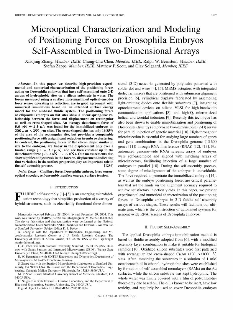
Fig. 1. (a) A 7� 12 array of Drosophila embryos positioned on a fluidic self-assembly positioning chip. Immobilization gold site size: 250 �m�100�m, pitch:1000�m� 1000�m. (b) Magnified view of a Drosophila embryo positioned and immobilized on the site through a thin film of polychlorotrifluoro-ethylene oil.
during injection experiments and hatching to prevent dehydra-tion of the embryos. The wafer is then immersed in water. Asa result, embryos were immobilized only at the oil-coveredsites. Embryos that had not been immobilized were removedby a gentle rinse. Fig. 1 shows an array of embryos positionedon a SAM chip with a 7 12 array of rectangular gold siteswith dimensions and a large pitch periodof to reduce embryo clustering. For thefluidic self assembly arrays to achieve high alignment yield,the immobilization force and potential energy profile must beoptimized.
III. MODELING AND SIMULATION OF FLUIDIC SELF-ASSEMBLY
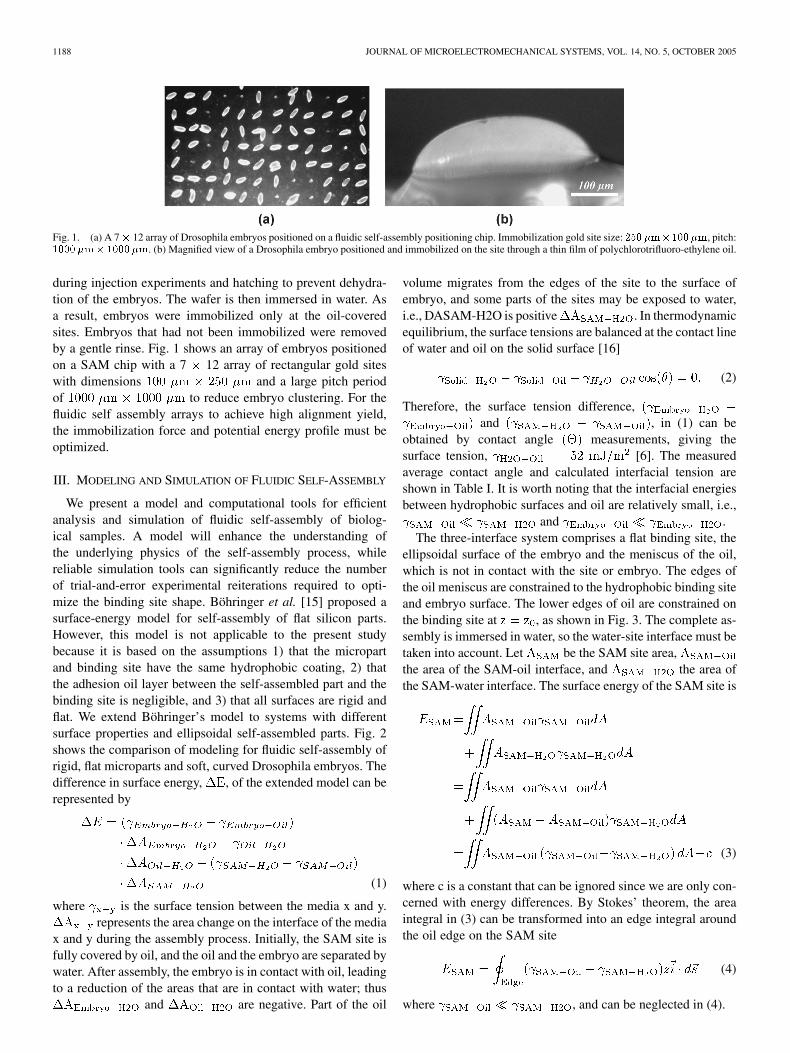
We present a model and computational tools for efficientanalysis and simulation of fluidic self-assembly of biolog-ical samples. A model will enhance the understanding ofthe underlying physics of the self-assembly process, whilereliable simulation tools can significantly reduce the numberof trial-and-error experimental reiterations required to opti-mize the binding site shape. Böhringer et al. [15] proposed asurface-energy model for self-assembly of flat silicon parts.However, this model is not applicable to the present studybecause it is based on the assumptions 1) that the micropartand binding site have the same hydrophobic coating, 2) thatthe adhesion oil layer between the self-assembled part and thebinding site is negligible, and 3) that all surfaces are rigid andflat. We extend Böhringer’s model to systems with differentsurface properties and ellipsoidal self-assembled parts. Fig. 2shows the comparison of modeling for fluidic self-assembly ofrigid, flat microparts and soft, curved Drosophila embryos. Thedifference in surface energy, , of the extended model can berepresented by
(1)
where is the surface tension between the media x and y.represents the area change on the interface of the media
x and y during the assembly process. Initially, the SAM site isfully covered by oil, and the oil and the embryo are separated bywater. After assembly, the embryo is in contact with oil, leadingto a reduction of the areas that are in contact with water; thus
and are negative. Part of the oil
volume migrates from the edges of the site to the surface ofembryo, and some parts of the sites may be exposed to water,i.e., DASAM-H2O is positive . In thermodynamicequilibrium, the surface tensions are balanced at the contact lineof water and oil on the solid surface [16]
(2)
Therefore, the surface tension difference,and , in (1) can be
obtained by contact angle measurements, giving thesurface tension, [6]. The measuredaverage contact angle and calculated interfacial tension areshown in Table I. It is worth noting that the interfacial energiesbetween hydrophobic surfaces and oil are relatively small, i.e.,
and .The three-interface system comprises a flat binding site, the
ellipsoidal surface of the embryo and the meniscus of the oil,which is not in contact with the site or embryo. The edges ofthe oil meniscus are constrained to the hydrophobic binding siteand embryo surface. The lower edges of oil are constrained onthe binding site at , as shown in Fig. 3. The complete as-sembly is immersed in water, so the water-site interface must betaken into account. Let be the SAM site area,the area of the SAM-oil interface, and the area ofthe SAM-water interface. The surface energy of the SAM site is
(3)
where c is a constant that can be ignored since we are only con-cerned with energy differences. By Stokes’ theorem, the areaintegral in (3) can be transformed into an edge integral aroundthe oil edge on the SAM site
(4)
where , and can be neglected in (4).
ZHANG et al.: MICROOPTICAL CHARACTERIZATION AND MODELING OF POSITIONING FORCES 1189
Fig. 2. Comparison of fluidic self-assembly models for: (a) a flat micropart and (b) a curved biological samples, such as a Drosophila embryo.
TABLE IAVERAGE CONTACT ANGLE AND INTERFACIAL ENERGY OF THE DROSOPHILA EMBRYO SELF-ASSEMBLY SYSTEM
The upper faces of the oil, the interfacial area between the oiland the embryo, are constrained on the ellipsoidal wall of theembryo at . The surface ten-sion energy is calculated by direct integration over the embryoarea covered by oil
(5)where is much less than and the con-stant c can be ignored.
The oil bridge (meniscus) consists of surface area exposedto water. This part of the surface may be moved freely withoutconstraints. The surface tension energy of the oil bridge is alsocalculated by direct integration over the interfacial area betweenthe oil and water
(6)
The restoring force applied on the embryo is the negative rateof change of total surface energy with respect to displacementof the rigid body. The principle of virtual work and the centralfinite difference method are employed to estimate the restoringforce while the embryo is moved from its central stable position
(7)
The surface of oil is first evolved to an equilibrium state withminimum energy. A very small linear movement, , is then ap-plied to the embryo relative to the SAM pad in both positive andnegative directions. The energy difference of and
is of order , so it is not necessary to re-evolvethe surface. Instead, the pressure is used to compensate for theslight volume change.
(8)
1190 JOURNAL OF MICROELECTROMECHANICAL SYSTEMS, VOL. 14, NO. 5, OCTOBER 2005
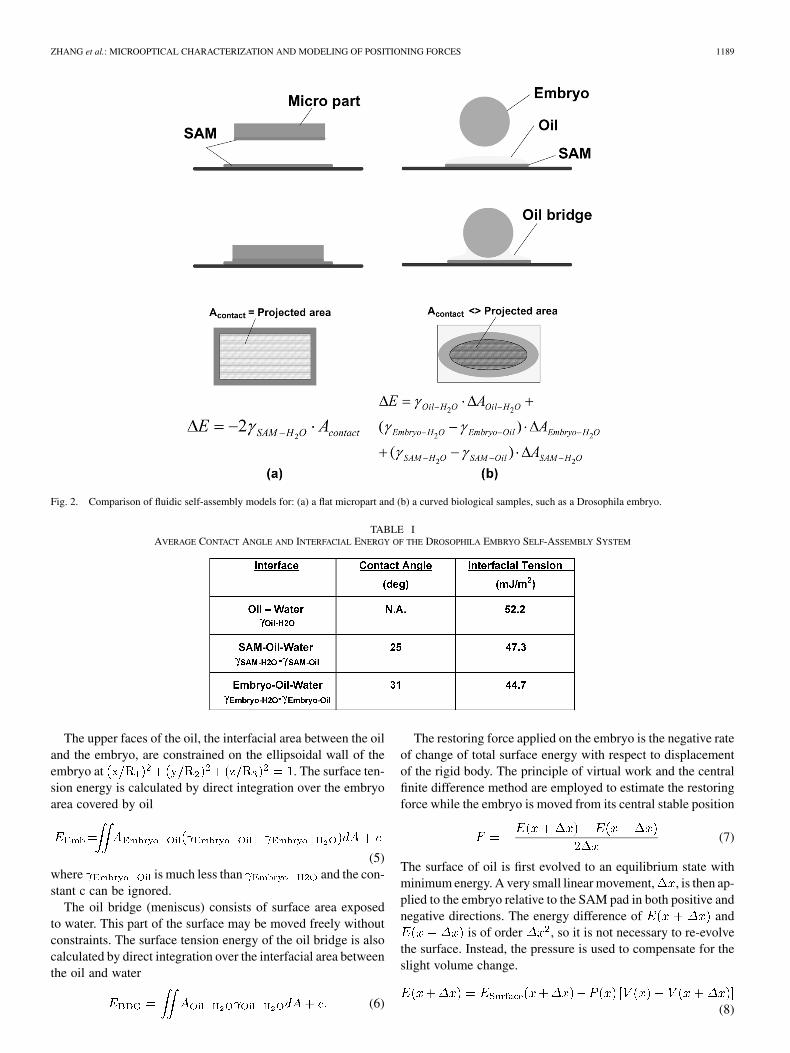
Fig. 3. (a) Simulated equilibrium shape of the oil bridge interfaces between Drosophila embryo and the 400�m�250 �m SAM binding site. (b) Geometry anddimensions of the embryo and fluidic self-assembly site used in simulation and experiments.
where is the surface energy recalculated afterthe displacement.
We programmed this model with (3)–(8) into SurfaceEvolver, a finite element software developed by Brakke [17].An equilibrium shape of the interfaces was calculated, asshown in the example of Fig. 3(a) for embryo binding sites of
.Fig. 3(b) shows the geometry and dimensions of the SAM
site as well as an “ideal” Drosophila embryo. The ideal embryohas an ellipsoidal shape with the major axis, , of 400 , andminor axes, and , of 200 . Two rectangular (
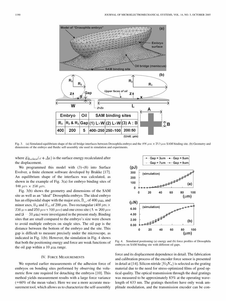
and ) and one cross site (and ) were investigated in the present study. Bindingsites that are small compared to the embryo’s size were chosento avoid multiple embryos on single sites. The oil gap is thedistance between the bottom of the embryo and the site. Thisgap is difficult to measure precisely under the microscope, asindicated in Fig. 1(b). However, the simulation in Fig. 4 showsthat both the positioning energy and force are weak functions ofthe oil gap within a 10 range.
IV. FORCE MEASUREMENTS
We reported earlier measurements of the adhesion force ofembryos on bonding sites performed by observing the volu-metric flow rate required for detaching the embryos [10]. Thismethod yields measurement results with a large force variance( 60% of the mean value). Here we use a more accurate mea-surement tool, which allows us to characterize the self-assembly
Fig. 4. Simulated positioning (a) energy and (b) force profiles of Drosophilaembryos on SAM binding site with different oil gaps.
force and its displacement dependence in detail. The fabricationand calibration process of the encoder force sensor is presentedin detail at [14]. Silicon nitride is selected as the gratingmaterial due to the need for stress-optimized films of good op-tical quality. The optical transmission through the dual gratingswas measured to be approximately 83% at the operating wave-length of 633 nm. The gratings therefore have only weak am-plitude modulation, and the transmission encoder can be con-
ZHANG et al.: MICROOPTICAL CHARACTERIZATION AND MODELING OF POSITIONING FORCES 1191
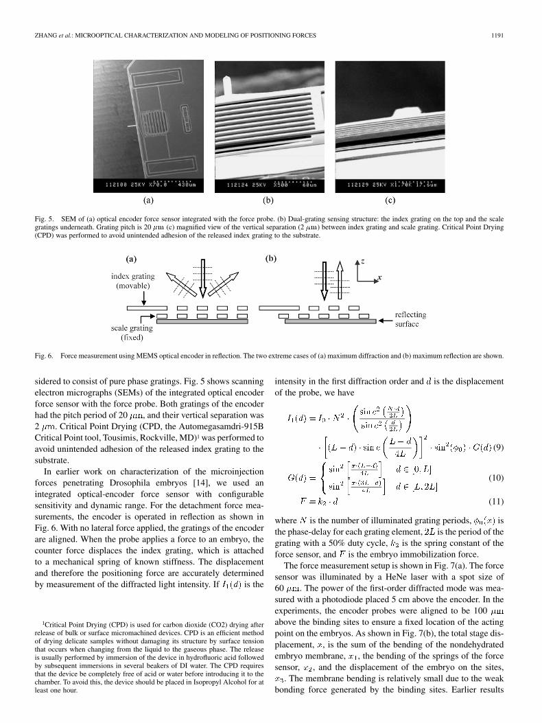
Fig. 5. SEM of (a) optical encoder force sensor integrated with the force probe. (b) Dual-grating sensing structure: the index grating on the top and the scalegratings underneath. Grating pitch is 20 �m (c) magnified view of the vertical separation (2 �m) between index grating and scale grating. Critical Point Drying(CPD) was performed to avoid unintended adhesion of the released index grating to the substrate.
Fig. 6. Force measurement using MEMS optical encoder in reflection. The two extreme cases of (a) maximum diffraction and (b) maximum reflection are shown.
sidered to consist of pure phase gratings. Fig. 5 shows scanningelectron micrographs (SEMs) of the integrated optical encoderforce sensor with the force probe. Both gratings of the encoderhad the pitch period of 20 , and their vertical separation was2 . Critical Point Drying (CPD, the Automegasamdri-915BCritical Point tool, Tousimis, Rockville, MD)1 was performed toavoid unintended adhesion of the released index grating to thesubstrate.
In earlier work on characterization of the microinjectionforces penetrating Drosophila embryos [14], we used anintegrated optical-encoder force sensor with configurablesensitivity and dynamic range. For the detachment force mea-surements, the encoder is operated in reflection as shown inFig. 6. With no lateral force applied, the gratings of the encoderare aligned. When the probe applies a force to an embryo, thecounter force displaces the index grating, which is attachedto a mechanical spring of known stiffness. The displacementand therefore the positioning force are accurately determinedby measurement of the diffracted light intensity. If is the
1Critical Point Drying (CPD) is used for carbon dioxide (CO2) drying afterrelease of bulk or surface micromachined devices. CPD is an efficient methodof drying delicate samples without damaging its structure by surface tensionthat occurs when changing from the liquid to the gaseous phase. The releaseis usually performed by immersion of the device in hydrofluoric acid followedby subsequent immersions in several beakers of DI water. The CPD requiresthat the device be completely free of acid or water before introducing it to thechamber. To avoid this, the device should be placed in Isopropyl Alcohol for atleast one hour.
intensity in the first diffraction order and is the displacementof the probe, we have
(9)
(10)
(11)
where is the number of illuminated grating periods, isthe phase-delay for each grating element, is the period of thegrating with a 50% duty cycle, is the spring constant of theforce sensor, and is the embryo immobilization force.
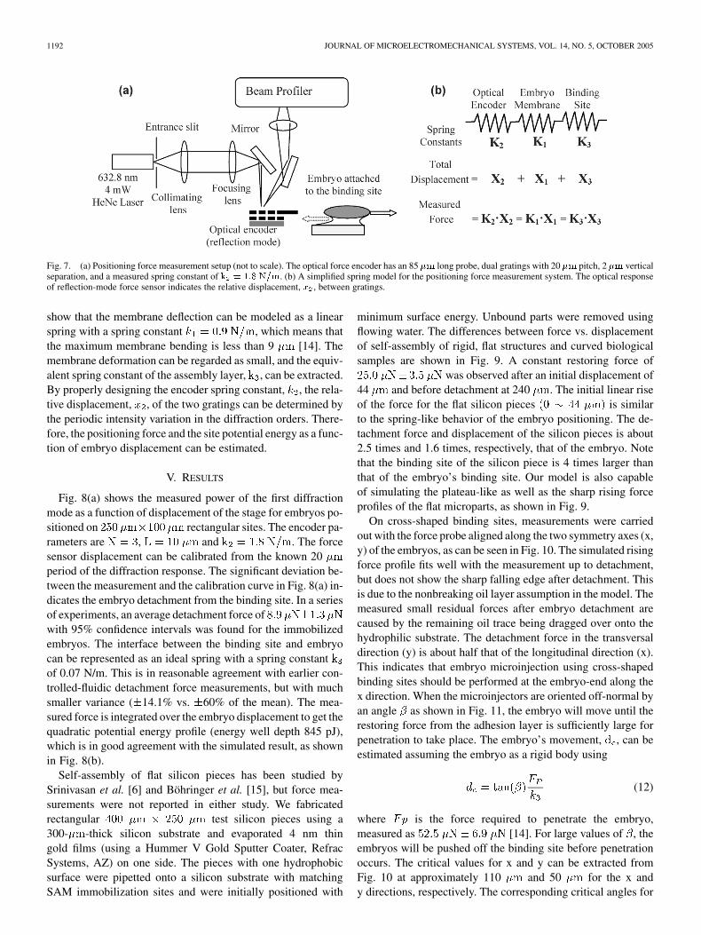
The force measurement setup is shown in Fig. 7(a). The forcesensor was illuminated by a HeNe laser with a spot size of60 . The power of the first-order diffracted mode was mea-sured with a photodiode placed 5 cm above the encoder. In theexperiments, the encoder probes were aligned to be 100above the binding sites to ensure a fixed location of the actingpoint on the embryos. As shown in Fig. 7(b), the total stage dis-placement, , is the sum of the bending of the nondehydratedembryo membrane, , the bending of the springs of the forcesensor, , and the displacement of the embryo on the sites,
. The membrane bending is relatively small due to the weakbonding force generated by the binding sites. Earlier results
1192 JOURNAL OF MICROELECTROMECHANICAL SYSTEMS, VOL. 14, NO. 5, OCTOBER 2005
Fig. 7. (a) Positioning force measurement setup (not to scale). The optical force encoder has an 85 �m long probe, dual gratings with 20 �m pitch, 2 �m verticalseparation, and a measured spring constant of k = 1:8 N=m. (b) A simplified spring model for the positioning force measurement system. The optical responseof reflection-mode force sensor indicates the relative displacement, x , between gratings.
show that the membrane deflection can be modeled as a linearspring with a spring constant , which means thatthe maximum membrane bending is less than 9 [14]. Themembrane deformation can be regarded as small, and the equiv-alent spring constant of the assembly layer, , can be extracted.By properly designing the encoder spring constant, , the rela-tive displacement, , of the two gratings can be determined bythe periodic intensity variation in the diffraction orders. There-fore, the positioning force and the site potential energy as a func-tion of embryo displacement can be estimated.
V. RESULTS
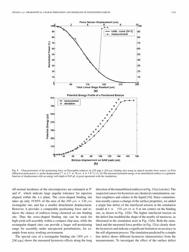
Fig. 8(a) shows the measured power of the first diffractionmode as a function of displacement of the stage for embryos po-sitioned on rectangular sites. The encoder pa-rameters are , and . The forcesensor displacement can be calibrated from the known 20period of the diffraction response. The significant deviation be-tween the measurement and the calibration curve in Fig. 8(a) in-dicates the embryo detachment from the binding site. In a seriesof experiments, an average detachment force ofwith 95% confidence intervals was found for the immobilizedembryos. The interface between the binding site and embryocan be represented as an ideal spring with a spring constantof 0.07 N/m. This is in reasonable agreement with earlier con-trolled-fluidic detachment force measurements, but with muchsmaller variance ( 14.1% vs. 60% of the mean). The mea-sured force is integrated over the embryo displacement to get thequadratic potential energy profile (energy well depth 845 pJ),which is in good agreement with the simulated result, as shownin Fig. 8(b).
Self-assembly of flat silicon pieces has been studied bySrinivasan et al. [6] and Böhringer et al. [15], but force mea-surements were not reported in either study. We fabricatedrectangular test silicon pieces using a300- -thick silicon substrate and evaporated 4 nm thingold films (using a Hummer V Gold Sputter Coater, RefracSystems, AZ) on one side. The pieces with one hydrophobicsurface were pipetted onto a silicon substrate with matchingSAM immobilization sites and were initially positioned with
minimum surface energy. Unbound parts were removed usingflowing water. The differences between force vs. displacementof self-assembly of rigid, flat structures and curved biologicalsamples are shown in Fig. 9. A constant restoring force of
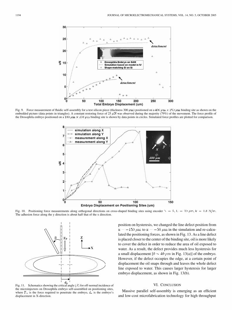
was observed after an initial displacement of44 and before detachment at 240 . The initial linear riseof the force for the flat silicon pieces is similarto the spring-like behavior of the embryo positioning. The de-tachment force and displacement of the silicon pieces is about2.5 times and 1.6 times, respectively, that of the embryo. Notethat the binding site of the silicon piece is 4 times larger thanthat of the embryo’s binding site. Our model is also capableof simulating the plateau-like as well as the sharp rising forceprofiles of the flat microparts, as shown in Fig. 9.
On cross-shaped binding sites, measurements were carriedout with the force probe aligned along the two symmetry axes (x,y) of the embryos, as can be seen in Fig. 10. The simulated risingforce profile fits well with the measurement up to detachment,but does not show the sharp falling edge after detachment. Thisis due to the nonbreaking oil layer assumption in the model. Themeasured small residual forces after embryo detachment arecaused by the remaining oil trace being dragged over onto thehydrophilic substrate. The detachment force in the transversaldirection (y) is about half that of the longitudinal direction (x).This indicates that embryo microinjection using cross-shapedbinding sites should be performed at the embryo-end along thex direction. When the microinjectors are oriented off-normal byan angle as shown in Fig. 11, the embryo will move until therestoring force from the adhesion layer is sufficiently large forpenetration to take place. The embryo’s movement, , can beestimated assuming the embryo as a rigid body using
(12)
where is the force required to penetrate the embryo,measured as [14]. For large values of , theembryos will be pushed off the binding site before penetrationoccurs. The critical values for x and y can be extracted fromFig. 10 at approximately 110 and 50 for the x andy directions, respectively. The corresponding critical angles for
ZHANG et al.: MICROOPTICAL CHARACTERIZATION AND MODELING OF POSITIONING FORCES 1193
Fig. 8. Characterization of the positioning force on Drosophila embryos on 250 �m � 100 �m binding sites using an optical encoder force sensor. (a) Firstdiffraction mode power vs. probe displacement (N = 3, L = 10 �m, k = 1:8 N=m). (b) The measured potential energy of an immobilized embryo is a quadraticfunction of displacement with an energy well depth of 845 pJ, in good agreement with the simulations.
off-normal incidence of the microinjectors are estimated at 9and 4 , which indicate large angular tolerance for injectorsaligned within the x-z plane. The cross-shaped binding sitetakes up only 19.85% of the area of therectangular site, and has a smaller detachment displacement.However, it provides a comparable positioning force and re-duces the chance of embryos being clustered on one bindingsite. Thus the cross-shaped binding site can be used forhigh-yield self-assembly within a compact chip area, while therectangular-shaped sites can provide a larger self-positioningrange for assembly under unexpected perturbations, for ex-ample from noisy working environment.
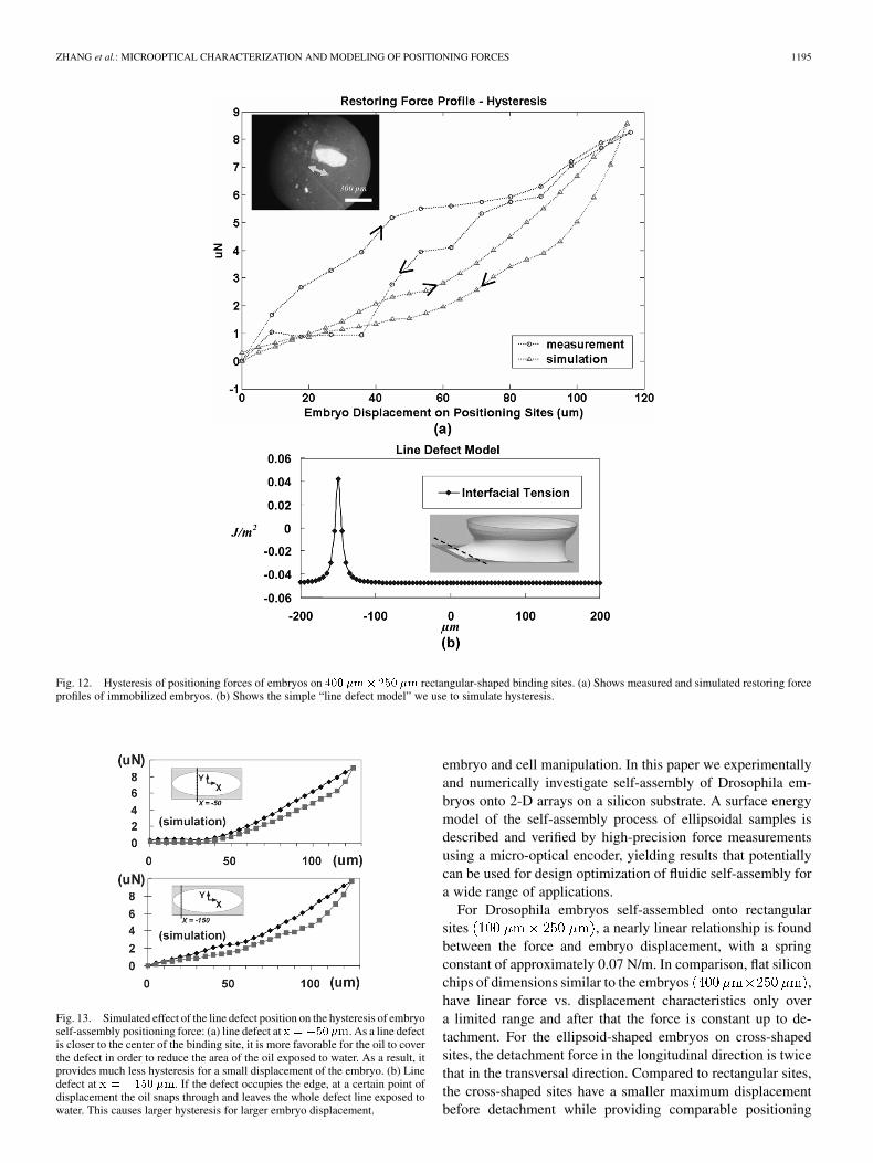
The special case of a rectangular binding siteshows the measured hysteresis effects along the long
direction of the immobilized embryos in Fig. 12(a) (circles). Thesuspected causes for hysteresis are chemical contamination, sur-face roughness and solutes in the liquid [16]. Since contamina-tion usually causes a change of the surface properties, we addeda single line defect of the interfacial tension in the simulationmodel at ( at site center) on the bindingsite, as shown in Fig. 12(b). The higher interfacial tension onthe defect line modified the shape of the nearby oil meniscus, asillustrated in the simulation inset in Fig. 12(b). Both the simu-lated and the measured force profiles in Fig. 12(a) clearly showthe hysteresis and indicate a significant limitation on accuracy inthe self-alignment process. The simulation predicted by a simpleline defect shows different hysteresis characteristics from themeasurements. To investigate the effect of the surface defect
1194 JOURNAL OF MICROELECTROMECHANICAL SYSTEMS, VOL. 14, NO. 5, OCTOBER 2005
Fig. 9. Force measurement of fluidic self-assembly for a test silicon piece (thickness 300 �m) positioned on a 400 �m� 250 �m binding site as shown on theembedded picture (data points in triangles). A constant restoring force of 25 �N was observed during the majority (79%) of the movement. The force profile ofthe Drosophila embryo positioned on a 100 �m� 250 �m binding site is shown by data points in circles. Simulated force profiles are plotted for comparison.
Fig. 10. Positioning force measurements along orthogonal directions on cross-shaped binding sites using encoder N = 5, L = 10 �m, k = 1:8 N=m.The adhesion force along the y direction is about half that of the x direction.
Fig. 11. Schematics showing the critical angle (�) for off-normal incidence ofthe microinjectors on Drosophila embryo self-assembled on positioning sites,where F is the force required to penetrate the embryo, d is the embryo’sdisplacement in X-direction.
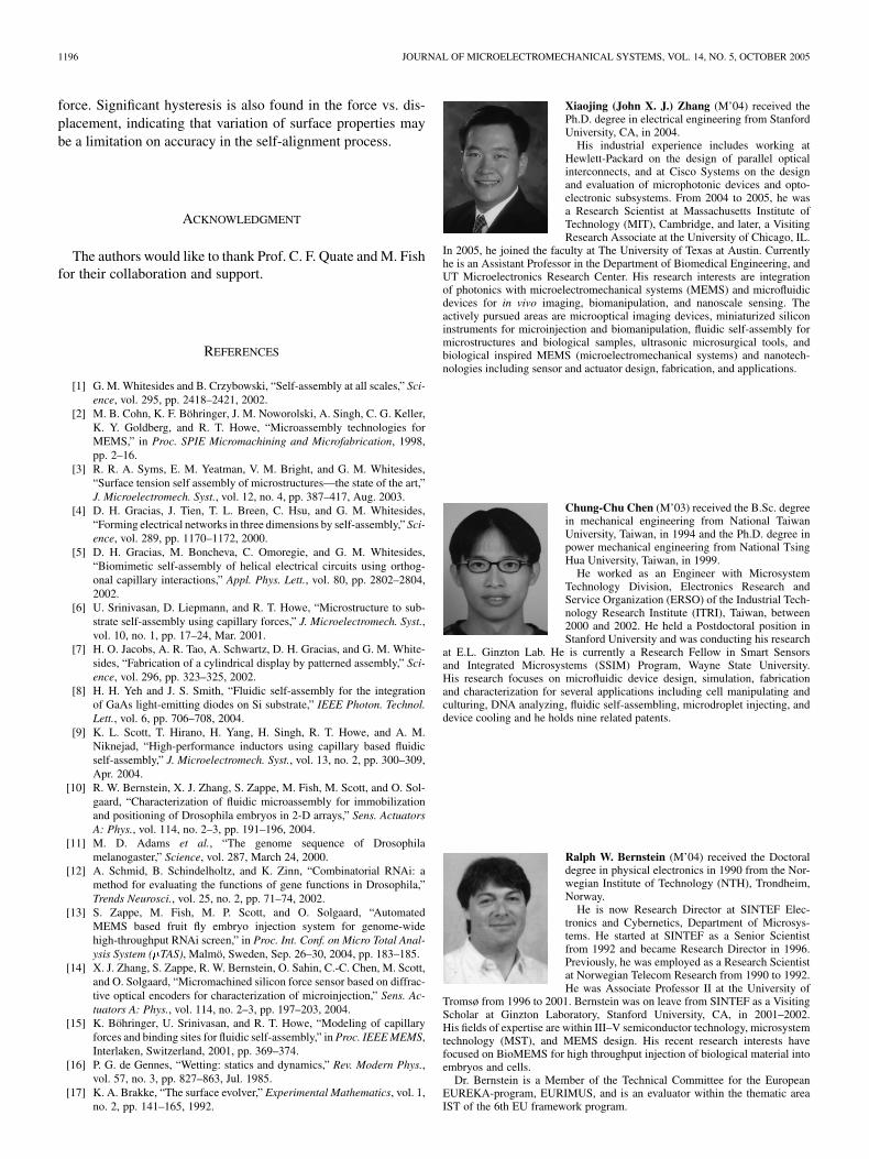
position on hysteresis, we changed the line defect position fromto in the simulation and re-calcu-
lated the positioning forces, as shown in Fig. 13. As a line defectis placed closer to the center of the binding site, oil is more likelyto cover the defect in order to reduce the area of oil exposed towater. As a result, the defect provides much less hysteresis fora small displacement [ in Fig. 13(a)] of the embryo.However, if the defect occupies the edge, at a certain point ofdisplacement the oil snaps through and leaves the whole defectline exposed to water. This causes larger hysteresis for largerembryo displacement, as shown in Fig. 13(b).
VI. CONCLUSION
Massive parallel self-assembly is emerging as an efficientand low-cost microfabrication technology for high throughput
ZHANG et al.: MICROOPTICAL CHARACTERIZATION AND MODELING OF POSITIONING FORCES 1195
Fig. 12. Hysteresis of positioning forces of embryos on 400 �m� 250 �m rectangular-shaped binding sites. (a) Shows measured and simulated restoring forceprofiles of immobilized embryos. (b) Shows the simple “line defect model” we use to simulate hysteresis.
Fig. 13. Simulated effect of the line defect position on the hysteresis of embryoself-assembly positioning force: (a) line defect at x = �50�m. As a line defectis closer to the center of the binding site, it is more favorable for the oil to coverthe defect in order to reduce the area of the oil exposed to water. As a result, itprovides much less hysteresis for a small displacement of the embryo. (b) Linedefect at x = �150 �m. If the defect occupies the edge, at a certain point ofdisplacement the oil snaps through and leaves the whole defect line exposed towater. This causes larger hysteresis for larger embryo displacement.
embryo and cell manipulation. In this paper we experimentallyand numerically investigate self-assembly of Drosophila em-bryos onto 2-D arrays on a silicon substrate. A surface energymodel of the self-assembly process of ellipsoidal samples isdescribed and verified by high-precision force measurementsusing a micro-optical encoder, yielding results that potentiallycan be used for design optimization of fluidic self-assembly fora wide range of applications.
For Drosophila embryos self-assembled onto rectangularsites , a nearly linear relationship is foundbetween the force and embryo displacement, with a springconstant of approximately 0.07 N/m. In comparison, flat siliconchips of dimensions similar to the embryos ,have linear force vs. displacement characteristics only overa limited range and after that the force is constant up to de-tachment. For the ellipsoid-shaped embryos on cross-shapedsites, the detachment force in the longitudinal direction is twicethat in the transversal direction. Compared to rectangular sites,the cross-shaped sites have a smaller maximum displacementbefore detachment while providing comparable positioning
1196 JOURNAL OF MICROELECTROMECHANICAL SYSTEMS, VOL. 14, NO. 5, OCTOBER 2005
force. Significant hysteresis is also found in the force vs. dis-placement, indicating that variation of surface properties maybe a limitation on accuracy in the self-alignment process.
ACKNOWLEDGMENT
The authors would like to thank Prof. C. F. Quate and M. Fishfor their collaboration and support.
REFERENCES
[1] G. M. Whitesides and B. Crzybowski, “Self-assembly at all scales,” Sci-ence, vol. 295, pp. 2418–2421, 2002.
[2] M. B. Cohn, K. F. Böhringer, J. M. Noworolski, A. Singh, C. G. Keller,K. Y. Goldberg, and R. T. Howe, “Microassembly technologies forMEMS,” in Proc. SPIE Micromachining and Microfabrication, 1998,pp. 2–16.
[3] R. R. A. Syms, E. M. Yeatman, V. M. Bright, and G. M. Whitesides,“Surface tension self assembly of microstructures—the state of the art,”J. Microelectromech. Syst., vol. 12, no. 4, pp. 387–417, Aug. 2003.
[4] D. H. Gracias, J. Tien, T. L. Breen, C. Hsu, and G. M. Whitesides,“Forming electrical networks in three dimensions by self-assembly,” Sci-ence, vol. 289, pp. 1170–1172, 2000.
[5] D. H. Gracias, M. Boncheva, C. Omoregie, and G. M. Whitesides,“Biomimetic self-assembly of helical electrical circuits using orthog-onal capillary interactions,” Appl. Phys. Lett., vol. 80, pp. 2802–2804,2002.
[6] U. Srinivasan, D. Liepmann, and R. T. Howe, “Microstructure to sub-strate self-assembly using capillary forces,” J. Microelectromech. Syst.,vol. 10, no. 1, pp. 17–24, Mar. 2001.
[7] H. O. Jacobs, A. R. Tao, A. Schwartz, D. H. Gracias, and G. M. White-sides, “Fabrication of a cylindrical display by patterned assembly,” Sci-ence, vol. 296, pp. 323–325, 2002.
[8] H. H. Yeh and J. S. Smith, “Fluidic self-assembly for the integrationof GaAs light-emitting diodes on Si substrate,” IEEE Photon. Technol.Lett., vol. 6, pp. 706–708, 2004.
[9] K. L. Scott, T. Hirano, H. Yang, H. Singh, R. T. Howe, and A. M.Niknejad, “High-performance inductors using capillary based fluidicself-assembly,” J. Microelectromech. Syst., vol. 13, no. 2, pp. 300–309,Apr. 2004.
[10] R. W. Bernstein, X. J. Zhang, S. Zappe, M. Fish, M. Scott, and O. Sol-gaard, “Characterization of fluidic microassembly for immobilizationand positioning of Drosophila embryos in 2-D arrays,” Sens. ActuatorsA: Phys., vol. 114, no. 2–3, pp. 191–196, 2004.
[11] M. D. Adams et al., “The genome sequence of Drosophilamelanogaster,” Science, vol. 287, March 24, 2000.
[12] A. Schmid, B. Schindelholtz, and K. Zinn, “Combinatorial RNAi: amethod for evaluating the functions of gene functions in Drosophila,”Trends Neurosci., vol. 25, no. 2, pp. 71–74, 2002.
[13] S. Zappe, M. Fish, M. P. Scott, and O. Solgaard, “AutomatedMEMS based fruit fly embryo injection system for genome-widehigh-throughput RNAi screen,” in Proc. Int. Conf. on Micro Total Anal-ysis System (�TAS), Malmö, Sweden, Sep. 26–30, 2004, pp. 183–185.
[14] X. J. Zhang, S. Zappe, R. W. Bernstein, O. Sahin, C.-C. Chen, M. Scott,and O. Solgaard, “Micromachined silicon force sensor based on diffrac-tive optical encoders for characterization of microinjection,” Sens. Ac-tuators A: Phys., vol. 114, no. 2–3, pp. 197–203, 2004.
[15] K. Böhringer, U. Srinivasan, and R. T. Howe, “Modeling of capillaryforces and binding sites for fluidic self-assembly,” in Proc. IEEE MEMS,Interlaken, Switzerland, 2001, pp. 369–374.
[16] P. G. de Gennes, “Wetting: statics and dynamics,” Rev. Modern Phys.,vol. 57, no. 3, pp. 827–863, Jul. 1985.
[17] K. A. Brakke, “The surface evolver,” Experimental Mathematics, vol. 1,no. 2, pp. 141–165, 1992.
Xiaojing (John X. J.) Zhang (M’04) received thePh.D. degree in electrical engineering from StanfordUniversity, CA, in 2004.
His industrial experience includes working atHewlett-Packard on the design of parallel opticalinterconnects, and at Cisco Systems on the designand evaluation of microphotonic devices and opto-electronic subsystems. From 2004 to 2005, he wasa Research Scientist at Massachusetts Institute ofTechnology (MIT), Cambridge, and later, a VisitingResearch Associate at the University of Chicago, IL.
In 2005, he joined the faculty at The University of Texas at Austin. Currentlyhe is an Assistant Professor in the Department of Biomedical Engineering, andUT Microelectronics Research Center. His research interests are integrationof photonics with microelectromechanical systems (MEMS) and microfluidicdevices for in vivo imaging, biomanipulation, and nanoscale sensing. Theactively pursued areas are microoptical imaging devices, miniaturized siliconinstruments for microinjection and biomanipulation, fluidic self-assembly formicrostructures and biological samples, ultrasonic microsurgical tools, andbiological inspired MEMS (microelectromechanical systems) and nanotech-nologies including sensor and actuator design, fabrication, and applications.
Chung-Chu Chen (M’03) received the B.Sc. degreein mechanical engineering from National TaiwanUniversity, Taiwan, in 1994 and the Ph.D. degree inpower mechanical engineering from National TsingHua University, Taiwan, in 1999.
He worked as an Engineer with MicrosystemTechnology Division, Electronics Research andService Organization (ERSO) of the Industrial Tech-nology Research Institute (ITRI), Taiwan, between2000 and 2002. He held a Postdoctoral position inStanford University and was conducting his research
at E.L. Ginzton Lab. He is currently a Research Fellow in Smart Sensorsand Integrated Microsystems (SSIM) Program, Wayne State University.His research focuses on microfluidic device design, simulation, fabricationand characterization for several applications including cell manipulating andculturing, DNA analyzing, fluidic self-assembling, microdroplet injecting, anddevice cooling and he holds nine related patents.
Ralph W. Bernstein (M’04) received the Doctoraldegree in physical electronics in 1990 from the Nor-wegian Institute of Technology (NTH), Trondheim,Norway.
He is now Research Director at SINTEF Elec-tronics and Cybernetics, Department of Microsys-tems. He started at SINTEF as a Senior Scientistfrom 1992 and became Research Director in 1996.Previously, he was employed as a Research Scientistat Norwegian Telecom Research from 1990 to 1992.He was Associate Professor II at the University of
Tromsø from 1996 to 2001. Bernstein was on leave from SINTEF as a VisitingScholar at Ginzton Laboratory, Stanford University, CA, in 2001–2002.His fields of expertise are within III–V semiconductor technology, microsystemtechnology (MST), and MEMS design. His recent research interests havefocused on BioMEMS for high throughput injection of biological material intoembryos and cells.
Dr. Bernstein is a Member of the Technical Committee for the EuropeanEUREKA-program, EURIMUS, and is an evaluator within the thematic areaIST of the 6th EU framework program.
ZHANG et al.: MICROOPTICAL CHARACTERIZATION AND MODELING OF POSITIONING FORCES 1197
Stefan Zappe (M’02) received the Diploma degreein electrical engineering from the Berlin Uni-versity of Technology, Germany, in 1996. From1996 to 2001, he worked as a Ph.D. student atthe Microsensor and Actuator Center at the BerlinUniversity of Technology.
In February 2001, he joined the Stanford Micro-photonics Laboratory at Stanford University, CA,as a Postdoctoral Researcher. His research activitiesinclude microfluidic systems for cell- and embryo-handling, sorting and micro-injection; biology of
fruit fly development; gene silencing by means of RNAi (RNA interference);microorifices for DNA shearing; microfluidic systems based reusable arraysfor DNA sequencing; integration of active and passive optical components intomicrosystems.
Matthew P. Scott received the B.S. and Ph.D. de-grees in biology from the Massachusetts Institute ofTechnology (MIT), Cambridge,
He did postdoctoral research at Indiana Universityand then joined the faculty at the University ofColorado at Boulder. In 1983, he moved to StanfordUniversity School of Medicine, where he is now Pro-fessor of Developmental Biology and of Genetics.He has published more than 130 papers and threepatents. His research areas are developmental ge-netics and cancer research, particularly the roles of
signaling systems and transcriptional regulation in embryonic development.His research employs genetics, genomics, cell biology, and molecular biologyin exploring how cells acquire their fates and are patterned. He is an editorof Current Opinion in Genetics and Development and of the Proceedings ofthe National Academy of Sciences. He is a past president of the Society forDevelopmental Biology, a member of the American Academy of Arts andSciences, and a member of the National Academy of Sciences. He is presentlychairing Stanford’s Bio-X program, which is designed to accelerate the comingtogether of engineering, physics, and chemistry with biology and medicine.
Olav Solgaard (S’88–M’90) received the B.S.degree in electrical engineering from the NorwegianInstitute of Technology and the M.S. and Ph.D.degrees in electrical engineering from StanfordUniversity, CA.
He held a Postdoctoral position at the Universityof California at Berkeley, and an Assistant Professor-ship at the University of California at Davis, beforejoining the faculty of the Department of ElectricalEngineering at Stanford University in 1999. Hisresearch interests are optical communication and
measurements with an emphasis on semiconductor fabrication and MEMStechnology applied to optical devices and systems. He has authored morethan 150 technical publications, and holds 18 patents. He is a co-founder ofSilicon Light Machines, Sunnyvale, CA, and an active consultant in the MEMSindustry.