Journal of Materials Processing Technology -...
9
Journal of Materials Processing Technology 214 (2014) 1307–1315 Contents lists available at ScienceDirect Journal of Materials Processing Technology jo ur nal ho me page: www.elsevier.com/locate/jmatprotec Manufacturing of ultrafine-grained titanium by caliber rolling in the laboratory and in industry G. Krállics a,∗ , J. Gubicza b , Z. Bezi c , I. Barkai c a Department of Materials Science and Engineering, Budapest University of Technology and Economics, H-1111, Bertalan L. strt. 7, Budapest, Hungary b Department of Materials Physics, Eötvös Loránd University, H-1117, Budapest, Hungary c Institute for Logistic and Production Engineering, Bay Zoltán Nonprofit Ltd for Applied Research, H-3519, Miskolc, Hungary a r t i c l e i n f o Article history: Received 13 September 2013 Received in revised form 31 January 2014 Accepted 8 February 2014 Available online 18 February 2014 Keywords: Grade 2 titanium Severe plastic deformation UFG microstructure Strength Ductility a b s t r a c t The mechanical properties and the microstructure of Grade 2 titanium semi-products processed by warm caliber rolling in both laboratory and industrial environments are studied. It is shown that this tech- nology yields ultrafine-grained (UFG) microstructure with high tensile strength and good ductility at room temperature. Finite element modelling (FEM) suggests that the effectiveness of caliber rolling in grain refinement is mainly caused by the large, homogeneous imposed strain, similar to conventional severe plastic deformation (SPD) methods. It is proved that the mechanical and microstructural proper- ties of titanium processed by the industrial equipment are similar to the characteristics of the material manufactured in the laboratory. This observation suggests that caliber rolling carried out in indus- trial environments may be a candidate technology in mass-production of UFG titanium with improved mechanical properties. © 2014 Elsevier B.V. All rights reserved. 1. Introduction Titanium is an ideal material for medical implants in the human body since it is chemically inert, does not react with human body fluids, and after a proper surface treatment the bone is able to adhere to it. From a physiological viewpoint, pure titanium is the optimum choice as an implant material since it does not contain other elements which may be toxic for the body. Severe plastic deformation (SPD) techniques are capable to refine the grain structure to 100–200 nm in pure Ti, thereby providing high strength semi-products for the fabrication of implants. Different SPD methods, such as Equal Channel Angular Pressing (ECAP) (Gunderov et al., 2013), multiple forging (MF) (Zherebtsov et al., 2004), twist extrusion (TE) (Stolyarov et al., 2005), hydrostatic extrusion (Pachla et al., 2008), accumulated roll bonding (ARB) (Milner et al., 2013), and asymmetrical rolling (Kim et al., 2011a) are used for production of ultrafine-grained (UFG) titanium. Most of these methods require special equipment and they are capable of producing only small quantities of materials. However, there is demand for UFG Ti in large amounts, therefore the objective of our research study is to develop an industrial production environment for UFG titanium. It is noted that high pressure torsion (HPT) is ∗ Corresponding author. Tel.: +36 1 4631445. E-mail address: [email protected] (G. Krállics). the most effective technique in refining grain structure of metals, but this method can process materials only in very small volumes, therefore HPT is out of the scope of this study. SPD processing of materials with hexagonal closed packed struc- ture (such as Ti) is often carried out at elevated temperatures due to the rigidity of the specimens at room temperature. However, warm SPD manufacturing processes are often followed by subsequent forming at room temperature or an annealing step in order to fur- ther improve the strength and the ductility of titanium. When very high strength is required, usually a final cold forming step is applied in the production procedure. The influence of these manufacturing processes on the microstructure and the mechanical performance of Ti is discussed in the literature overview presented below. Among the warm SPD methods ECAP is the most frequently used technique. Stolyarov et al. (1999) processed a titanium rod by seven passes of ECAP in the temperature range of 500–450 ◦ C (referred to as case A throughout this manuscript), which yielded a refined mean grain size of ∼300 nm. Stolyarov et al. (2003) applied a two-step SPD procedure in order to obtain UFG Ti with signif- icantly enhanced strength. Eight passes of warm ECAP via route B c at 450 ◦ C was first used, resulting in a grain size of ∼350 nm (case B). The Ti billets were further processed by repetitive cold rolling and annealing at 300 ◦ C (case C). Latysh et al. (2006) used a combination of warm ECAP with warm drawing to produce Grade 2 UFG titanium. In this process four (case D) and eight passes (case E) of ECAP at 450 ◦ C led to grain sizes of 500 and 350 nm, respectively. http://dx.doi.org/10.1016/j.jmatprotec.2014.02.015 0924-0136/© 2014 Elsevier B.V. All rights reserved.
Transcript of Journal of Materials Processing Technology -...
Ml
Ga
b
c
a
ARRAA
KGSUSD
1
bflatcpgsS(2e(aoodrf
h0
Journal of Materials Processing Technology 214 (2014) 1307–1315
Contents lists available at ScienceDirect
Journal of Materials Processing Technology
jo ur nal ho me page: www.elsev ier .com/ locate / jmatprotec
anufacturing of ultrafine-grained titanium by caliber rolling in theaboratory and in industry
. Krállicsa,∗, J. Gubiczab, Z. Bezic, I. Barkai c
Department of Materials Science and Engineering, Budapest University of Technology and Economics, H-1111, Bertalan L. strt. 7, Budapest, HungaryDepartment of Materials Physics, Eötvös Loránd University, H-1117, Budapest, HungaryInstitute for Logistic and Production Engineering, Bay Zoltán Nonprofit Ltd for Applied Research, H-3519, Miskolc, Hungary
r t i c l e i n f o
rticle history:eceived 13 September 2013eceived in revised form 31 January 2014ccepted 8 February 2014vailable online 18 February 2014
a b s t r a c t
The mechanical properties and the microstructure of Grade 2 titanium semi-products processed by warmcaliber rolling in both laboratory and industrial environments are studied. It is shown that this tech-nology yields ultrafine-grained (UFG) microstructure with high tensile strength and good ductility atroom temperature. Finite element modelling (FEM) suggests that the effectiveness of caliber rolling ingrain refinement is mainly caused by the large, homogeneous imposed strain, similar to conventional
eywords:rade 2 titaniumevere plastic deformationFG microstructuretrengthuctility
severe plastic deformation (SPD) methods. It is proved that the mechanical and microstructural proper-ties of titanium processed by the industrial equipment are similar to the characteristics of the materialmanufactured in the laboratory. This observation suggests that caliber rolling carried out in indus-trial environments may be a candidate technology in mass-production of UFG titanium with improvedmechanical properties.
© 2014 Elsevier B.V. All rights reserved.
. Introduction
Titanium is an ideal material for medical implants in the humanody since it is chemically inert, does not react with human bodyuids, and after a proper surface treatment the bone is able todhere to it. From a physiological viewpoint, pure titanium ishe optimum choice as an implant material since it does notontain other elements which may be toxic for the body. Severelastic deformation (SPD) techniques are capable to refine therain structure to 100–200 nm in pure Ti, thereby providing hightrength semi-products for the fabrication of implants. DifferentPD methods, such as Equal Channel Angular Pressing (ECAP)Gunderov et al., 2013), multiple forging (MF) (Zherebtsov et al.,004), twist extrusion (TE) (Stolyarov et al., 2005), hydrostaticxtrusion (Pachla et al., 2008), accumulated roll bonding (ARB)Milner et al., 2013), and asymmetrical rolling (Kim et al., 2011a)re used for production of ultrafine-grained (UFG) titanium. Mostf these methods require special equipment and they are capablef producing only small quantities of materials. However, there is
emand for UFG Ti in large amounts, therefore the objective of ouresearch study is to develop an industrial production environmentor UFG titanium. It is noted that high pressure torsion (HPT) is∗ Corresponding author. Tel.: +36 1 4631445.E-mail address: [email protected] (G. Krállics).
ttp://dx.doi.org/10.1016/j.jmatprotec.2014.02.015924-0136/© 2014 Elsevier B.V. All rights reserved.
the most effective technique in refining grain structure of metals,but this method can process materials only in very small volumes,therefore HPT is out of the scope of this study.
SPD processing of materials with hexagonal closed packed struc-ture (such as Ti) is often carried out at elevated temperatures due tothe rigidity of the specimens at room temperature. However, warmSPD manufacturing processes are often followed by subsequentforming at room temperature or an annealing step in order to fur-ther improve the strength and the ductility of titanium. When veryhigh strength is required, usually a final cold forming step is appliedin the production procedure. The influence of these manufacturingprocesses on the microstructure and the mechanical performanceof Ti is discussed in the literature overview presented below.
Among the warm SPD methods ECAP is the most frequentlyused technique. Stolyarov et al. (1999) processed a titanium rodby seven passes of ECAP in the temperature range of 500–450 ◦C(referred to as case A throughout this manuscript), which yielded arefined mean grain size of ∼300 nm. Stolyarov et al. (2003) applieda two-step SPD procedure in order to obtain UFG Ti with signif-icantly enhanced strength. Eight passes of warm ECAP via routeBc at 450 ◦C was first used, resulting in a grain size of ∼350 nm(case B). The Ti billets were further processed by repetitive cold
rolling and annealing at 300 ◦C (case C). Latysh et al. (2006) used acombination of warm ECAP with warm drawing to produce Grade 2UFG titanium. In this process four (case D) and eight passes (case E)of ECAP at 450 ◦C led to grain sizes of 500 and 350 nm, respectively.
1308 G. Krállics et al. / Journal of Materials Process
Fig. 1. Mechanical properties of Grade 2 titanium processed by warm ECAP andwarm ECAP + conventional metal forming processes. YS: yield strength, UTS: ulti-moc
TfacEtianstcuTFEi
apb
aa
F(tc
ate tensile strength, A: elongation to failure. YSan, UTSan and Aan denote the valuesbtained for the initial material. The capital letters at the bottom specify the pro-essing methods described in the text.
he thermo-mechanical treatment after 4 and 8 ECAP passesurther refined the grain size to 350 and 250 nm, respectively. Kangnd Kim (2010) investigated the microstructure of Ti processed by aombination of warm multi-pass ECAP and cold extrusion. A T-typeCAP apparatus was developed in order to improve the efficiency ofhe common ECAP procedure in grain refinement and the mechan-cal performance of the finished products. After 5 passes of ECAPn average grain size of 960 nm was reached (case F), which didot change during subsequent cold extrusion (case G). While thetrength of Ti usually increased due to ECAP technique and furtherhermo-mechanical treatments or cold forming processes, in manyases the ductility of the material decreased. The yield strength, theltimate tensile strength and the elongation to failure obtained fori processed by warm ECAP-based SPD procedures are shown inig. 1. The highest strength achieved by the combination of warmCAP and conventional processes is 2.5 times higher than that in thenitial state. High strength is accompanied by sufficient ductility.
Besides ECAP other SPD processes, such as symmetric andsymmetric rolling, TE and ARB, can also improve the mechanicalerformance of Ti. The mechanical properties of samples processedy these techniques are shown in Fig. 2.
Li et al. (2012) produced nano-grained Grade 2 titanium withn average grain size of 80 nm by the combination of asymmetricnd symmetric rolling at room temperature (case H). The rolled
ig. 2. Mechanical properties of Grade 2 titanium processed by warm SPD processesnot based on ECAP). YS: yield strength, UTS: ultimate tensile strength, A: elongationo failure. YSan, UTSan and Aan denote the values obtained for the initial material. Theapital letters at the bottom specify the processing methods described in the text.
ing Technology 214 (2014) 1307–1315
Ti samples possessed UFG microstructure, and the grain sizeremained smaller than 200 nm even after annealing the specimensat 400 ◦C for 30 min. Kim et al. (2011b) examined the effect of theroll speed ratio (SR) on the microstructure, texture and mechanicalproperties of commercially pure Ti during differential speed rollingat 400 ◦C for SR = 3 (case I) and SR = 5 (case J). Kim et al. (2011a)produced pure titanium sheets with UFG microstructures byhigh-ratio differential speed rolling at different SR values and tem-peratures. The strengthening was increased by either increasingSR or decreasing the processing temperature. In warm rolling, thesamples were preheated to 400 ◦C, and the roll surface temperaturewas maintained at 200 ◦C. The rolling procedures resulted in meangrain sizes between 180 and 500 nm (case K). Milner et al. (2013)processed sheet samples of Grade 2 titanium by seven consecutiveARB cycles at 450 ◦C (case L). At the end of the procedure thegrain size was about 100 nm. Stolyarov et al. (2005) tested themicrostructure and the mechanical properties as well as thethermal stability of commercially pure titanium subjected to TE. Acombined manufacturing process (TE and rolling, case M) resultedin an additional refinement of the microstructure, which remainedthermally stable up to 300–350 ◦C. Subsequent low-temperatureannealing increased the ductility of the SPD-processed titanium,retaining its enhanced strength. It should be noted that thestrength achieved by rolling, TE and ARB techniques was slightlylower than that obtained by ECAP-based processes. At the sametime, outstanding ductility was achieved by the TE method.
Multi-pass caliber rolling is a continuous multiple forging pro-cess, known as one of the most powerful SPD methods (Inoue et al.,2007). For instance, the warm caliber rolling process has been usedto produce UFG steels (Oh et al., 2011). In the present paper themicrostructure and the mechanical properties of Grade 2 Ti pro-cessed by caliber rolling are investigated. The rolling process wascarried out both in laboratory and industrial environments. It willbe shown that caliber rolling carried out in an industrial environ-ment might be a candidate technology for mass-production of UFGtitanium with improved mechanical properties.
2. Experimental and modeling procedures
2.1. Rolling experiments in laboratory
Grade 2 titanium specimens with 200 mm in length and 30 mmin diameter in an annealed condition (annealing at 650 ◦C for 2 h,then cooling in air) were used for the laboratory rolling tests.The initial mechanical properties were as follows: yield strength,YS = 332 MPa, ultimate tensile strength, UTS = 439 MPa, reductionin area, Z = 58%, elongation to failure, A = 22%, strain energy densityto fracture, Wf = 412 J/cm3. A twin motor rolling mill with the powerof 2 × 7.5 kW was used in the experiments. The diameter of the rollwas 180 mm. The roll stand can be used in both symmetrical andasymmetrical modes (Fig. 3).
The first mode enables both flat and caliber rolling processes.The caliber rolls used in the present study are shown in Fig. 4.
The laboratory caliber rolling was carried out on samples pre-heated to 450 ◦C. Four reductions were performed in the first partof the process. The roll speed was 6 rpm. After the first part of therolling procedure the specimen was reheated to 450 ◦C. The secondpart of the rolling process was performed in six passes using thesame heating procedure between subsequent passes as applied inthe first part of the process. In the first and second parts of the pro-cedure different roll pairs were used, as shown in Fig. 4. After the
last pass in the second part a final diameter of 8 mm was achieved.The shape and the size of the roll cavities for the ten passes areshown in Fig. 5. The basic parameters of the process are listed inTable 1.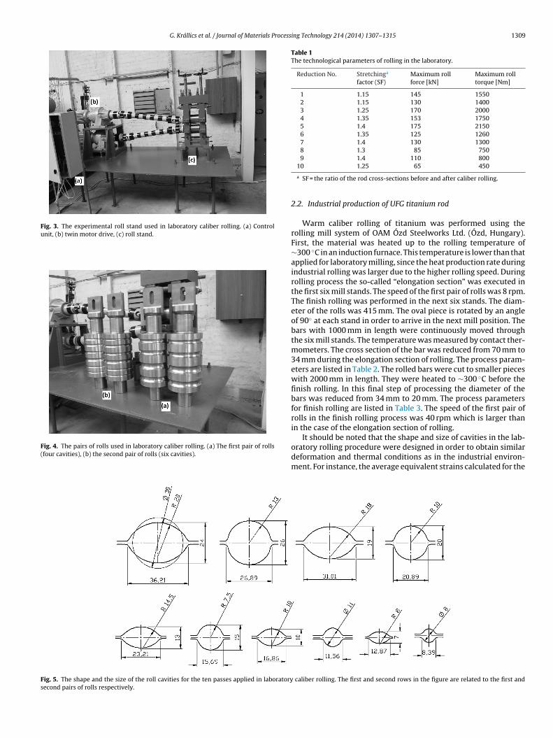
G. Krállics et al. / Journal of Materials Processing Technology 214 (2014) 1307–1315 1309
Fig. 3. The experimental roll stand used in laboratory caliber rolling. (a) Controlunit, (b) twin motor drive, (c) roll stand.
Fig. 4. The pairs of rolls used in laboratory caliber rolling. (a) The first pair of rolls(four cavities), (b) the second pair of rolls (six cavities).
Table 1The technological parameters of rolling in the laboratory.
Reduction No. Stretchinga
factor (SF)Maximum rollforce [kN]
Maximum rolltorque [Nm]
1 1.15 145 15502 1.15 130 14003 1.25 170 20004 1.35 153 17505 1.4 175 21506 1.35 125 12607 1.4 130 13008 1.3 85 7509 1.4 110 800
Fig. 5. The shape and the size of the roll cavities for the ten passes applied in laboratorysecond pairs of rolls respectively.
10 1.25 65 450
a SF = the ratio of the rod cross-sections before and after caliber rolling.
2.2. Industrial production of UFG titanium rod
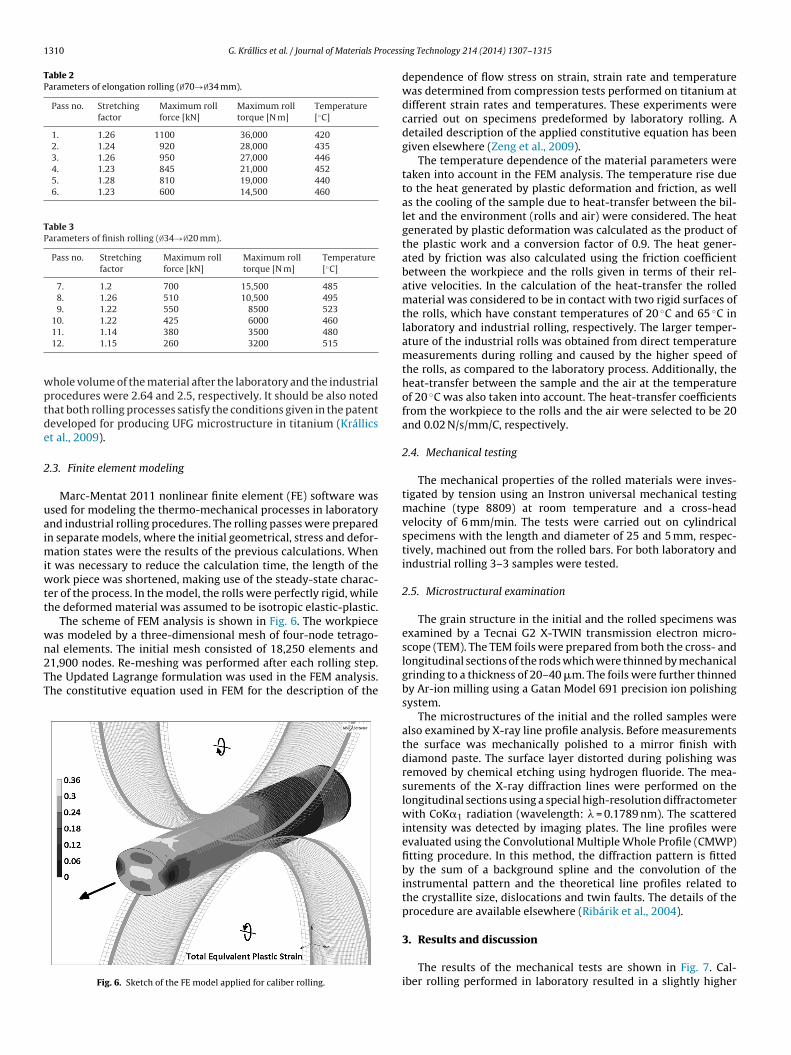
Warm caliber rolling of titanium was performed using therolling mill system of OAM Ózd Steelworks Ltd. (Ózd, Hungary).First, the material was heated up to the rolling temperature of∼300 ◦C in an induction furnace. This temperature is lower than thatapplied for laboratory milling, since the heat production rate duringindustrial rolling was larger due to the higher rolling speed. Duringrolling process the so-called “elongation section” was executed inthe first six mill stands. The speed of the first pair of rolls was 8 rpm.The finish rolling was performed in the next six stands. The diam-eter of the rolls was 415 mm. The oval piece is rotated by an angleof 90◦ at each stand in order to arrive in the next mill position. Thebars with 1000 mm in length were continuously moved throughthe six mill stands. The temperature was measured by contact ther-mometers. The cross section of the bar was reduced from 70 mm to34 mm during the elongation section of rolling. The process param-eters are listed in Table 2. The rolled bars were cut to smaller pieceswith 2000 mm in length. They were heated to ∼300 ◦C before thefinish rolling. In this final step of processing the diameter of thebars was reduced from 34 mm to 20 mm. The process parametersfor finish rolling are listed in Table 3. The speed of the first pair ofrolls in the finish rolling process was 40 rpm which is larger thanin the case of the elongation section of rolling.
It should be noted that the shape and size of cavities in the lab-oratory rolling procedure were designed in order to obtain similardeformation and thermal conditions as in the industrial environ-ment. For instance, the average equivalent strains calculated for the
caliber rolling. The first and second rows in the figure are related to the first and
1310 G. Krállics et al. / Journal of Materials Process
Table 2Parameters of elongation rolling (∅70→∅34 mm).
Pass no. Stretchingfactor
Maximum rollforce [kN]
Maximum rolltorque [N m]
Temperature[◦C]
1. 1.26 1100 36,000 4202. 1.24 920 28,000 4353. 1.26 950 27,000 4464. 1.23 845 21,000 4525. 1.28 810 19,000 4406. 1.23 600 14,500 460
Table 3Parameters of finish rolling (∅34→∅20 mm).
Pass no. Stretchingfactor
Maximum rollforce [kN]
Maximum rolltorque [N m]
Temperature[◦C]
7. 1.2 700 15,500 4858. 1.26 510 10,500 4959. 1.22 550 8500 523
10. 1.22 425 6000 460
wptde
2
uaimiwtt
wn2TT
11. 1.14 380 3500 48012. 1.15 260 3200 515
hole volume of the material after the laboratory and the industrialrocedures were 2.64 and 2.5, respectively. It should be also notedhat both rolling processes satisfy the conditions given in the patenteveloped for producing UFG microstructure in titanium (Krállicst al., 2009).
.3. Finite element modeling
Marc-Mentat 2011 nonlinear finite element (FE) software wassed for modeling the thermo-mechanical processes in laboratorynd industrial rolling procedures. The rolling passes were preparedn separate models, where the initial geometrical, stress and defor-
ation states were the results of the previous calculations. Whent was necessary to reduce the calculation time, the length of the
ork piece was shortened, making use of the steady-state charac-er of the process. In the model, the rolls were perfectly rigid, whilehe deformed material was assumed to be isotropic elastic-plastic.
The scheme of FEM analysis is shown in Fig. 6. The workpieceas modeled by a three-dimensional mesh of four-node tetrago-al elements. The initial mesh consisted of 18,250 elements and
1,900 nodes. Re-meshing was performed after each rolling step.he Updated Lagrange formulation was used in the FEM analysis.he constitutive equation used in FEM for the description of theFig. 6. Sketch of the FE model applied for caliber rolling.
ing Technology 214 (2014) 1307–1315
dependence of flow stress on strain, strain rate and temperaturewas determined from compression tests performed on titanium atdifferent strain rates and temperatures. These experiments werecarried out on specimens predeformed by laboratory rolling. Adetailed description of the applied constitutive equation has beengiven elsewhere (Zeng et al., 2009).
The temperature dependence of the material parameters weretaken into account in the FEM analysis. The temperature rise dueto the heat generated by plastic deformation and friction, as wellas the cooling of the sample due to heat-transfer between the bil-let and the environment (rolls and air) were considered. The heatgenerated by plastic deformation was calculated as the product ofthe plastic work and a conversion factor of 0.9. The heat gener-ated by friction was also calculated using the friction coefficientbetween the workpiece and the rolls given in terms of their rel-ative velocities. In the calculation of the heat-transfer the rolledmaterial was considered to be in contact with two rigid surfaces ofthe rolls, which have constant temperatures of 20 ◦C and 65 ◦C inlaboratory and industrial rolling, respectively. The larger temper-ature of the industrial rolls was obtained from direct temperaturemeasurements during rolling and caused by the higher speed ofthe rolls, as compared to the laboratory process. Additionally, theheat-transfer between the sample and the air at the temperatureof 20 ◦C was also taken into account. The heat-transfer coefficientsfrom the workpiece to the rolls and the air were selected to be 20and 0.02 N/s/mm/C, respectively.
2.4. Mechanical testing
The mechanical properties of the rolled materials were inves-tigated by tension using an Instron universal mechanical testingmachine (type 8809) at room temperature and a cross-headvelocity of 6 mm/min. The tests were carried out on cylindricalspecimens with the length and diameter of 25 and 5 mm, respec-tively, machined out from the rolled bars. For both laboratory andindustrial rolling 3–3 samples were tested.
2.5. Microstructural examination
The grain structure in the initial and the rolled specimens wasexamined by a Tecnai G2 X-TWIN transmission electron micro-scope (TEM). The TEM foils were prepared from both the cross- andlongitudinal sections of the rods which were thinned by mechanicalgrinding to a thickness of 20–40 �m. The foils were further thinnedby Ar-ion milling using a Gatan Model 691 precision ion polishingsystem.
The microstructures of the initial and the rolled samples werealso examined by X-ray line profile analysis. Before measurementsthe surface was mechanically polished to a mirror finish withdiamond paste. The surface layer distorted during polishing wasremoved by chemical etching using hydrogen fluoride. The mea-surements of the X-ray diffraction lines were performed on thelongitudinal sections using a special high-resolution diffractometerwith CoK�1 radiation (wavelength: � = 0.1789 nm). The scatteredintensity was detected by imaging plates. The line profiles wereevaluated using the Convolutional Multiple Whole Profile (CMWP)fitting procedure. In this method, the diffraction pattern is fittedby the sum of a background spline and the convolution of theinstrumental pattern and the theoretical line profiles related tothe crystallite size, dislocations and twin faults. The details of theprocedure are available elsewhere (Ribárik et al., 2004).
3. Results and discussion
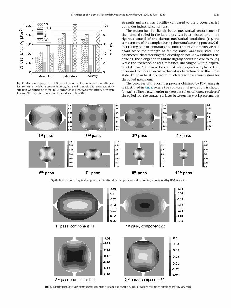
The results of the mechanical tests are shown in Fig. 7. Cal-iber rolling performed in laboratory resulted in a slightly higher
G. Krállics et al. / Journal of Materials Process
Fig. 7. Mechanical properties of Grade 2 titanium in the initial state and after cal-iber rolling in the laboratory and industry. YS: yield strength, UTS: ultimate tensilestrength, A: elongation to failure, Z: reduction in area, Wf: strain energy density tofracture. The experimental error of the values is about 8%.
Fig. 8. Distribution of equivalent plastic strain after different
Fig. 9. Distribution of strain components after the first and the se
ing Technology 214 (2014) 1307–1315 1311
strength and a similar ductility compared to the process carriedout under industrial conditions.
The reason for the slightly better mechanical performance ofthe material rolled in the laboratory can be attributed to a morerigorous control of the thermo-mechanical conditions (e.g. thetemperature of the sample) during the manufacturing process. Cal-iber rolling both in laboratory and industrial environments yieldedabout twice the strength as for the initial annealed state. Theparameters characterizing the ductility do not show uniform ten-dencies. The elongation to failure slightly decreased due to rollingwhile the reduction of area remained unchanged within experi-mental error. At the same time, the strain energy density to fractureincreased to more than twice the value characteristic to the initialstate. This can be attributed to much larger flow stress values forthe rolled specimens.
The progress of the forming process obtained by FEM analysisis illustrated in Fig. 8, where the equivalent plastic strain is shownfor each rolling pass. In order to keep the spherical cross-section ofthe rolled rod, the contact surfaces between the workpiece and the
passes of caliber rolling, as obtained by FEM analysis.
cond passes of caliber rolling, as obtained by FEM analysis.

1312 G. Krállics et al. / Journal of Materials Processing Technology 214 (2014) 1307–1315
Fa
roriwwsttUuppncasta
tlti
Fa
in the laboratory yielded significant grain refinement in the UFG
ig. 10. The temperature at selected points of the cross-section for titanium rod as function of time during the first part of laboratory rolling, as obtained by FEM.
olls were varied cyclically. For instance, in Fig. 8 the top-bottomr the left-right surface pairs of the rod are in contact with theolls during the odd or even number of rolling passes. In practice,n laboratory the rolls were in fixed positions and the workpiece
as rotated, while for industrial experiments the rod orientationas unchanged and the rolls were rotated. From the results pre-
ented in Fig. 8 it is clear that at the end of the forming processhe local plastic strain is about three, similar to SPD-processing byhree passes of ECAP, which should be large enough for producingFG microstructure. Another important result is that a relativelyniform strain distribution is achieved at the end of the formingrocedure. Additionally, caliber rolling yields a cyclic deformationrocess. This leads to more effective grain refinement. The cyclicature of caliber rolling is illustrated in Fig. 9 where the normalomponents of the logarithmic strain tensor are shown. The darknd bright areas in the figure correspond to volumes with compres-ive and tensile stress components, respectively. It is clearly visiblehat dark areas in the first pass became bright in the second passnd vice versa.
Figs. 10 and 11 show the temperature as a function of rolling
ime obtained by FEM for some selected points in the cross sectionocated in the middle of the rod during the first and second parts ofhe rolling procedure, respectively. During rolling the temperaturencreased at points inside the pre-heated rod due to the generationig. 11. The temperature at selected points of the cross-section for titanium rod as function of time during the second part of laboratory rolling, as obtained by FEM.
Fig. 12. The equivalent plastic strain at selected points of the cross-section for tita-nium rod as a function of time during the first part of laboratory rolling, as obtainedby FEM.
of heat by plastic deformation. At the same time, the temperatureof the pre-heated surfaces decreased due to the contact with thecool rolls. As the orientation of the contact surfaces changes cycli-cally by increasing the number of passes, at surface points A andC the temperature decreased and increased periodically. After thefirst part of rolling, the workpiece was heated up again to the initialtemperature (450 ◦C in the case of laboratory rolling). The equiv-alent strain values versus the rolling time for these points in thecross-section are shown in Figs. 12 and 13, for the first and secondparts of rolling. A similar FEM analysis was also performed for thecase of industrial rolling, but the results of this calculation are notshown here. It should be noted that the latter FEM analysis revealeda larger temperature increment for industrial rolling due to a higherrolling rate, in accordance with experiments.
The results of the microstructural investigations can be sum-marized as follows. TEM images (not shown here) revealed that thegrain size in the initial Ti material was between 1 and 4 �m. Rolling
regime, as illustrated in the TEM images of Fig. 14 obtained at theend of the manufacturing process. In the cross-section the averagegrain size was about 300 nm. In the longitudinal section the grains
Fig. 13. The equivalent plastic strain at selected points of the cross-section for tita-nium rod as a function of time during the second part of laboratory rolling, asobtained by FEM.

G. Krállics et al. / Journal of Materials Processing Technology 214 (2014) 1307–1315 1313
F Ti. (a) Cross- and (b) longitudinal sections. The rolling direction is vertical in figure (b).T
w1rTt
glstbmtto
iestsd
Table 4The crystallite size and the dislocation density obtained by X-ray line profile analysison the longitudinal sections of the initial material, and the samples processed byrolling in laboratory and industry.
Sample Crystallite size[nm]
Dislocation density[1014 m−2]
Initial 220 ± 20 0.5 ± 0.3
FT
ig. 14. Dark field TEM images illustrating the grain structure in laboratory-rolledhe insets show the corresponding diffraction patterns.
ere elongated with an average width and length of 300 nm and �m, respectively. Electron diffraction patterns for the specimenolled in the laboratory are also presented in the insets of Fig. 14.he transition from a spotted to a ring-like diffraction pattern dueo rolling also confirms the strong grain-refinement.
After industrial rolling the grains are also elongated in the lon-itudinal section, as revealed in Fig. 15. The average width and theength of the grains are 500 nm and 1 �m, respectively. In the cross-ection, considerable elongation of the grains was not observed. Inhis section the mean grain size is 500 nm. It can be concluded thatoth laboratory and industrial rolling procedures resulted in UFGicrostructures, but the grain refinement was slightly stronger in
he former case, as also indicated by the electron diffraction pat-erns. The smaller grain size can explain the slightly higher strengthf the material rolled in the laboratory.
The crystallite size and the dislocation density were determinedn the longitudinal sections by X-ray line profile analysis. As anxample, fitting for the sample processed by industrial rolling is
hown in Fig. 16. The open circles and the solid line representhe measured data and the fitted curves, respectively. The inten-ity is plotted on a logarithmic scale. The inset shows a part of theiffractogram with larger magnification. In the inset the intensity isig. 15. Dark field TEM images illustrating the grain structure in industrially rolled Ti. (a)
he insets show the corresponding diffraction patterns.
Laboratory rolling 62 ± 8 4.9 ± 0.5Industrial rolling 127 ± 15 3.7 ± 0.4
plotted on a linear scale and the difference between the measuredand the fitted patterns is also shown at the bottom. The crystallitesize and the dislocation density obtained for the initial materialand the samples processed by laboratory and industry rolling arelisted in Table 4. The crystallite size determined by X-ray line pro-file analysis is smaller than the grain size obtained by TEM, whichhas already been observed for other plastically deformed metals(Gubicza and Ungár, 2007). This phenomenon can be attributed to
the fact that the crystallites are equivalent to the domains in themicrostructure which scatter X-rays coherently. As the coherencyof X-rays breaks even if they are scattered from volumes havingquite small misorientations (1–2◦), the crystallite size correspondsCross- and (b) longitudinal sections. The rolling direction is horizontal in figure (b).

1314 G. Krállics et al. / Journal of Materials Process
Fi
r(dTttto(baa(mt
ibcs
Ffgtuso
ig. 16. Line profile fitting for the longitudinal section of the sample processed byndustrial rolling.
ather to the subgrain size in severely deformed microstructuresGubicza and Ungár, 2007). Table 4 reveals that the crystallite sizeecreased while the dislocation density increased due to rolling.he reduction in the crystallite size and the increment in disloca-ion density are stronger in the laboratory rolling procedure, buthe difference between the dislocation densities obtained by thewo types of rolling is not very large. It is noted that the grain sizebtained on the cross-section of the sample rolled in the laboratory300 nm) is close to the value (265 nm) determined for Ti processedy eight passes of ECAP at 400–450 ◦C and subsequently rolledt room temperature to a total strain (reduction in cross-sectionrea) of 73% (Zhu et al., 2003). At the same time, the crystallite size40 nm) and the dislocation density (30 × 1014 m−2) in the speci-
ens rolled after ECAP were smaller and larger, respectively, thanhe values obtained in the present experiments.
Finally, caliber rolling procedures applied in laboratory andndustry are placed on the map illustrating the relationship
etween grain size and mechanical properties for Grade 2 Ti pro-essed by different warm SPD methods. Fig. 17 shows the yieldtrength and the elongation to failure data as a function of theig. 17. The yield strength and the elongation to failure as a function of the grain sizeor UFG Grade 2 titanium processed by warm SPD techniques. Curves represent theeneral trends suggested by the literature data (Pachla et al., 2008) for UFG Grade 2itanium. Some characteristic values of the yield strength and the elongation to fail-re determined for warm ECAP-processed samples are denoted by grey circles andquares, respectively. The solid black symbols indicate the present results obtainedn the specimens processed by laboratory and industrial caliber rolling.
ing Technology 214 (2014) 1307–1315
grain size determined for UFG Grade 2 titanium after warm SPD-processing (Pachla et al., 2008). It can be seen that the mechanicalproperties of the present caliber rolled samples fit the generaltrends obtained from fitting the data given in the literature (rep-resented by the curves in Fig. 17). Some literature data obtainedon Ti processed by warm SPD without additional forming proce-dure are also shown in the figure. It can be concluded that caliberrolling both in laboratory and industrial conditions results in simi-lar mechanical properties to those obtained by conventional warmSPD processes. However, industrial caliber rolling yields one ortwo orders of magnitude larger volumes of UFG Ti per unit timethan other SPD routes, therefore this procedure may be a candi-date in mass-production of titanium with improved mechanicalbehavior.
4. Conclusions
1. It was shown that warm caliber rolling carried out on Grade2 titanium at about 450 ◦C in the laboratory yielded an UFGmicrostructure with high strength and good ductility. The grainsize and the mechanical properties were similar to values char-acteristic of samples processed by conventional SPD methods,such as ECAP.
2. Finite element modeling proved that caliber rolling yielded largeand nearly homogeneous plastic strain in the material, which isan important condition for effective grain refinement through-out the material. The cyclical nature of the process was alsorevealed which might also contribute to evolution of the UFGmicrostructure.
3. Caliber rolling carried out in industrial environment yielded sim-ilar small grain size and improved mechanical properties as theprocess performed in the laboratory. It was proposed that thistechnology might be a candidate process for mass-production ofUFG titanium with high strength and good ductility. This mayopen a new gate to commercialization of SPD-processed mate-rials.
Acknowledgement
This study was supported by the Hungarian Scientific ResearchFund, OTKA, Grant nos. K-100500 and 109021.
References
Gubicza, J., Ungár, T., 2007. Characterization of defect structures in nanocrystallinematerials by X-ray line profile analysis. Zeitschrift fur Kristallographie 222,567–579.
Gunderov, D.V., Polyakov, A.V., Semenova, I.P., Raab, G.I., Churakova, A.A., Gimalt-dinova, E.I., Sabirov, I., Segurado, J., Sitdikov, V.D., Alexandrov, I.V., Enikeev,N.A., Valiev, R.Z., 2013. Evolution of microstructure,macrotexture and mechan-ical properties of commercially pure Ti during ECAP-conform processing anddrawing. Materials Science and Engineering A 562, 128–136.
Inoue, T., Yin, F., Kimura, Y., 2007. Strain distribution and microstructural evolutionin multi-pass warm caliber rolling. Materials Science and Engineering A 466,114–122.
Kang, D.H., Kim, T.W., 2010. Mechanical behavior and microstructural evolutionof commercially pure titanium in enhanced multi-pass equal channel angularpressing and cold extrusion. Materials and Design 31, 54–60.
Kim, H.S., Yoo, S.J., Ahn, J.W., Kim, D.H., Kim, W.J., 2011a. Ultrafine grained titaniumsheets with high strength and high corrosion resistance. Materials Science andEngineering A 528, 8479–8485.
Kim, W.J., Yoo, S.J., Jeong, H.T., Kim, D.M., Choeb, B.H., Lee, J.B., 2011b. Effect of thespeed ratio on grain refinement and texture development in pure Ti duringdifferential speed rolling. Scripta Materialia 64, 49–52.
Krállics, Gy., Bézi, Z., Barkai, I., Latysh, V., 2009. Procedure for manufacturing ofultra-fine grain metallic product. Hungarian Patent Announcement “PO900723”,November 19.
Latysh, V., Krallics, Gy., Alexandrov, I., Fodor, A., 2006. Application of bulk nanos-tructured materials in medicine. Current Applied Physics 6, 262–266.
Li, Z., Fu, L., Fu, B., 2012. Effects of annealing on microstructure and mechanicalproperties of nano-grained titanium produced by combination of asymmetricand symmetric rolling. Materials Science and Engineering A 558, 309–318.

rocess
M
O
P
R
S
G. Krállics et al. / Journal of Materials P
ilner, J.L., Farha, F.A., Bunget, C., Kurfess, T., Hammond, V.H., 2013. Grainrefinement and mechanical properties of CP-Ti processed by warmaccumulative roll bonding. Materials Science and Engineering A 561,109–117.
h, Y.S., Son, I.H., Jung, K.H., Kim, D.K., Lee, D.L., Im, Y.T., 2011. Effect of initialmicrostructure on mechanical properties in warm caliber rolling of high carbonsteel. Materials Science and Engineering A 528, 5833–5839.
achla, W., Kulczyk, M., Sus-Ryszkowska, M., Mazur, A., Krzysztof, J., Kurzydlowski,K.J., 2008. Nanocrystalline titanium produced by hydrostatic extrusion. Journalof Materials Processing Technology 205, 173–182.
ibárik, G., Gubicza, J., Ungár, T., 2004. Correlation between strength and microstruc-
ture of ball milled Al-Mg alloys determined by X-ray diffraction. MaterialsScience and Engineering A 387–389, 343–347.tolyarov, V.V., Zhu, Y.T., Lowe, T.C., Islamgaliev, R.K., Valiev, R.Z., 1999. A twostep SPD processing of ultrafine-grained titanium. NanoStructured Materials11, 947–954.
ing Technology 214 (2014) 1307–1315 1315
Stolyarov, V.V., Beigel’zimer, Ya.E., Orlov, D.V., Valiev, R.Z., 2005. Refinement ofmicrostructure and mechanical properties of titanium processed by twist extru-sion and subsequent rolling. The Physics of Metals and Metallography 99,204–211.
Stolyarov, V.V., Zhu, Y.T., Alexandrov, I.V., Lowe, T.C., Valiev, R.Z., 2003. Grain refine-ment and properties of pure Ti processed by warm ECAP and cold rolling.Materials Science and Engineering A 343, 43–50.
Zherebtsov, S.V., Salishchev, G.A., Galeyev, R.M., Valiakhmetov, O.R., Mironov, S.Yu.,Semiatin, S.L., 2004. Production of submicrocrystalline structure in large-scaleTi–6Al–4V billet by warm severe deformation processing. Scripta Materialia 51,1147–1151.
Zeng, Z., Jonsson, S., Zhang, Y., 2009. Constitutive equations for pure titanium atelevated temperatures. Materials Science and Engineering A 505, 116–119.
Zhu, Y.T., Huang, J.Y., Gubicza, J., Ungár, T., Wang, Y.M., Ma, E., Valiev, R.Z., 2003.Nanostructures in Ti processed by severe plastic deformation. Journal of Mate-rials Research 18, 1908–1917.


![TENSILE ANALYSIS OF 3D PRINTER FILAMENTS - uni-miskolc.humicrocad/publikaciok/2018/b/B_Halapi_David.pdf · Material classification of 3D printing[2] Fig. 3 illustrates two comparisons,](https://static.fdocuments.in/doc/165x107/5e060548dd713f738c04f2a0/tensile-analysis-of-3d-printer-filaments-uni-microcadpublikaciok2018bbhalapidavidpdf.jpg)


![AN ANALYSIS OF THE METROLOGY TECHNIQUES TO IMPROVE …microcad/publikaciok/... · Quality management systems – Fundamentals and vocabulary. [3] DURAKBASA N.M., OSANNA P.H.: Micro](https://static.fdocuments.in/doc/165x107/5f08aab27e708231d42322d5/an-analysis-of-the-metrology-techniques-to-improve-microcadpublikaciok-quality.jpg)