Journal of Cranio-Maxillo-Facial Surgery · implanted mandible shows displacement fields and...
13
The feasibility of a custom-made endoprosthesis in mandibular reconstruction: Implant design and finite element analysis Manuel Pinheiro * , J.L. Alves Department of Mechanical Engineering, University of Minho, Guimar~ aes, Braga, Portugal article info Article history: Paper received 17 June 2015 Accepted 2 October 2015 Available online 20 October 2015 Keywords: Cephalometry Endosseous implantation Mandibular reconstruction Mandibular prosthesis implantation Finite element analysis abstract This work studies the feasibility of custom-made endoprosthesis in the reconstruction of major mandibular defects. The natural anatomical and occlusal relations are used to accurately reconstruct a mandibular defect. The customized implant allows the accurate restoration of the facial profile and aesthetics. The biomechanical behaviour of mandibular endoprosthesis was validated with Finite Element Analysis for three masticatory tasks, namely incisal, right molar and left group clenching. The implanted mandible shows displacement fields and stress distributions very similar to the intact mandible. The strain fields observed along the boneeimplant interface may promote bone maintenance and ingrowth. The preliminary results show that this implant may be a reliable alternative to other prosthetic mandibular reconstruction approaches. © 2015 European Association for Cranio-Maxillo-Facial Surgery. Published by Elsevier Ltd. All rights reserved. 1. Introduction Mandibular reconstruction is often needed to compensate bone loss related with trauma, inflammatory disease, and benign or malignant tumours. Mandibular resection caused by malignant or aggressive odontogenic tumours can originate extensive de- fects on the orofacial cavity, including bone, oral mucosa, mus- cles, and teeth. The primary objective of a mandibulectomy is to remove all deceased tissues and provide quality of life to the patient. The surgical procedure should provide both functional and cosmetic rehabilitation (Peled et al., 2005; Goh et al., 2008; Flint et al., 2010). Therefore, orofacial reconstruction should restore the oral competency, maintain occlusal relationships be- tween the remaining teeth, allows for prosthetic dental restora- tion, restore bone continuity and the contour of the lower third of the human face, as well as the facial symmetry (Taylor, 1982; Goh et al., 2008). The implanted material should provide sufficient height for adequate muscle attachment, provide the possibility for dental implant insertion, and allow the restoration of the normal occlusion and articulation of the mandible (Goh et al., 2008). During mandibular reconstruction considerable amounts of soft and hard tissue may be needed for the complete rehabilitation of the lower facial region. The most common donor sites are the iliac crest, the radius forearm, the scapula, and the fibula (Peled et al., 2005). Each donor site differs in the quality and quantity of bone and soft tissue available; in the quality of the vascular pedicle; in the possibility of bone reshaping and placement of dental implants in a second stage surgery (Goh et al., 2008). The fibular flaps and the iliac flaps provide the most suitable bone stock for dental rehabil- itation, and are preferred over other donor sites (Miloro et al., 2004). The microvascular free flaps are currently seen as the gold standard for mandibular reconstruction. The first microvascular free fibular bone flap transfer was re- ported in Hidalgo (1989), and was used to reconstruct a segmental defect on the mandible. This technique has revolutionized oro- mandibular reconstruction, since it enabled a compound graft to be transferred from the donor site with bone and soft tissue, without damaging their own vascular supply, to the head and neck regions (Bak et al., 2010). Success rates near 100% have been reported with this technique, even in the treatment of the most adverse situations (Gurtner and Evans, 2000). Currently, free microvascular flaps are used to reconstruct large mandibular defects (Haughey et al., 1994), where there is inadequate soft tissue or the recipient site has already been subjected to radiation ( € Ostrup and Fredrickson, 1975), to manage chronic infections, to correct previous surgeries, and in primary mandibular reconstruction due to aggressive odontogenic tumours (Disa and Cordeiro, 2000; Peled et al., 2005). * Corresponding author. Department of Mechanical Engineering, Escola de Engenharia - Universidade do Minho, Campus de Azur em, 4804-533 Guimar~ aes, Portugal. Tel.: þ351 934 074 020. E-mail address: [email protected] (M. Pinheiro). Contents lists available at ScienceDirect Journal of Cranio-Maxillo-Facial Surgery journal homepage: www.jcmfs.com http://dx.doi.org/10.1016/j.jcms.2015.10.004 1010-5182/© 2015 European Association for Cranio-Maxillo-Facial Surgery. Published by Elsevier Ltd. All rights reserved. Journal of Cranio-Maxillo-Facial Surgery 43 (2015) 2116e2128
Transcript of Journal of Cranio-Maxillo-Facial Surgery · implanted mandible shows displacement fields and...

lable at ScienceDirect
Journal of Cranio-Maxillo-Facial Surgery 43 (2015) 2116e2128
Contents lists avai
Journal of Cranio-Maxillo-Facial Surgery
journal homepage: www.jcmfs.com
The feasibility of a custom-made endoprosthesis in mandibularreconstruction: Implant design and finite element analysis
Manuel Pinheiro*, J.L. AlvesDepartment of Mechanical Engineering, University of Minho, Guimar~aes, Braga, Portugal
a r t i c l e i n f o
Article history:Paper received 17 June 2015Accepted 2 October 2015Available online 20 October 2015
Keywords:CephalometryEndosseous implantationMandibular reconstructionMandibular prosthesis implantationFinite element analysis
* Corresponding author. Department of MechanEngenharia - Universidade do Minho, Campus de APortugal. Tel.: þ351 934 074 020.
E-mail address: [email protected] (M.
http://dx.doi.org/10.1016/j.jcms.2015.10.0041010-5182/© 2015 European Association for Cranio-M
a b s t r a c t
This work studies the feasibility of custom-made endoprosthesis in the reconstruction of majormandibular defects. The natural anatomical and occlusal relations are used to accurately reconstruct amandibular defect. The customized implant allows the accurate restoration of the facial profile andaesthetics. The biomechanical behaviour of mandibular endoprosthesis was validated with FiniteElement Analysis for three masticatory tasks, namely incisal, right molar and left group clenching. Theimplanted mandible shows displacement fields and stress distributions very similar to the intactmandible. The strain fields observed along the boneeimplant interface may promote bone maintenanceand ingrowth. The preliminary results show that this implant may be a reliable alternative to otherprosthetic mandibular reconstruction approaches.
© 2015 European Association for Cranio-Maxillo-Facial Surgery. Published by Elsevier Ltd. All rightsreserved.
1. Introduction
Mandibular reconstruction is often needed to compensatebone loss related with trauma, inflammatory disease, and benignor malignant tumours. Mandibular resection caused by malignantor aggressive odontogenic tumours can originate extensive de-fects on the orofacial cavity, including bone, oral mucosa, mus-cles, and teeth. The primary objective of a mandibulectomy is toremove all deceased tissues and provide quality of life to thepatient. The surgical procedure should provide both functionaland cosmetic rehabilitation (Peled et al., 2005; Goh et al., 2008;Flint et al., 2010). Therefore, orofacial reconstruction shouldrestore the oral competency, maintain occlusal relationships be-tween the remaining teeth, allows for prosthetic dental restora-tion, restore bone continuity and the contour of the lower third ofthe human face, as well as the facial symmetry (Taylor, 1982; Gohet al., 2008). The implanted material should provide sufficientheight for adequate muscle attachment, provide the possibilityfor dental implant insertion, and allow the restoration of thenormal occlusion and articulation of the mandible (Goh et al.,2008).
ical Engineering, Escola dezur�em, 4804-533 Guimar~aes,
Pinheiro).
axillo-Facial Surgery. Published by
During mandibular reconstruction considerable amounts of softand hard tissue may be needed for the complete rehabilitation ofthe lower facial region. The most common donor sites are the iliaccrest, the radius forearm, the scapula, and the fibula (Peled et al.,2005). Each donor site differs in the quality and quantity of boneand soft tissue available; in the quality of the vascular pedicle; inthe possibility of bone reshaping and placement of dental implantsin a second stage surgery (Goh et al., 2008). The fibular flaps and theiliac flaps provide the most suitable bone stock for dental rehabil-itation, and are preferred over other donor sites (Miloro et al.,2004). The microvascular free flaps are currently seen as the goldstandard for mandibular reconstruction.
The first microvascular free fibular bone flap transfer was re-ported in Hidalgo (1989), and was used to reconstruct a segmentaldefect on the mandible. This technique has revolutionized oro-mandibular reconstruction, since it enabled a compound graft to betransferred from the donor site with bone and soft tissue, withoutdamaging their own vascular supply, to the head and neck regions(Bak et al., 2010). Success rates near 100% have been reported withthis technique, even in the treatment of the most adverse situations(Gurtner and Evans, 2000). Currently, free microvascular flaps areused to reconstruct large mandibular defects (Haughey et al., 1994),where there is inadequate soft tissue or the recipient site hasalready been subjected to radiation (€Ostrup and Fredrickson, 1975),to manage chronic infections, to correct previous surgeries, and inprimary mandibular reconstruction due to aggressive odontogenictumours (Disa and Cordeiro, 2000; Peled et al., 2005).
Elsevier Ltd. All rights reserved.

M. Pinheiro, J.L. Alves / Journal of Cranio-Maxillo-Facial Surgery 43 (2015) 2116e2128 2117
Free microvascular fibular reconstruction has numerous ad-vantages against other microvascular free flap techniques. Never-theless, this procedure cannot be performed in patients that havedeficient lower limb vascularization. For instance, patients withischaemic diseases of the lower limbs, arteriosclerosis, small lengthof the fibula pedicle, and limited thickness of the soft tissue are noteligible for this type of mandibular reconstruction (Ferri et al.,1997). As an alternative, several authors addressed mandibularreconstruction through the development of custom implantabledevices. Custom devices aim to reduce the time and complexity ofthe surgical procedure, to enhance the aesthetic outcome, and toreduce or even eliminate the need for bone harvesting. Two typesof custom-made implants may be identified: there are the titaniumtrays that shape and provide mechanical support to the bone graftscollected from one of the possible donor sites, for instance, thecustom-made titanium trays proposed in Samman et al. (1999) andin Singare et al. (2004), and custom-made plates that use screws tofix the implant to the remaining mandible. In the second type ofimplants one can find the solutions proposed in Peckitt (1999) andin Li et al. (2014). More recently, the company Xilloc Medical BVdocumented the development and implantation of a completecustom-made mandibular implant, obtained from the patient's CTscan (Nickels, 2012).
A different approach for bridging a mandibular defect wasproposed in Tideman (2006): an endoprosthesis composed byseveral modules and a screw-based locking system for the accuratemandibular reconstruction was proposed. The successful implan-tation of a cemented titanium alloy (Ti-6Al-4V) modular endo-prosthesis in animals was reported in Lee et al. (2008). After 3months of follow-up, there were no signs of implant loosening.There was no masticatory function loss and no signs of occlusionproblems. Nevertheless, two of the modular endoprosthesis sys-tems failed due to the screw connection between the differentmodules of the implant. The modular endoprosthesis concept wasalso applied to the ascending ramus and mandibular condyle byGoh et al. (2009b), as an alternative to the traditional temporo-mandibular joint replacement techniques. Normal temporoman-dibular joint function, mouth opening and occlusionwere observedpostoperatively.
One of the major problems associated with all the aforemen-tioned custom-made implants is the failure of the screwed con-nections at the boneeimplant interface. This problem has beenwidely described in the literature. Several authors concluded thatplates fixed in the buccal aspect of the mandible have to withstandunfavourable forces that often lead to loosening of the screws andfracturing of the plates (Kim and Donoff, 1992; Spencer et al., 1999;Shibahara et al., 2002). In a finite element study, Knoll et al. (2006)concluded thatmasticatory loads and high chewing forcesmay leadto fatigue failure of the reconstruction plates and/or to screwloosening. A wider flat plate design with square screw configura-tion was proposed to bridge a mandibular angle defect and tominimize the stress concentration across the cortical bone andplate screws. Ramos et al. (2011) analysed the stress along custom-made temporomandibular joint implants, and observed highdetrimental mechanical stresses at the level of the first screwregardless of the implant geometry used to interface the mandib-ular bone. Similarly, Wong et al. (2012a,b) proposed a modularendoprosthesis with a different screwed configuration. High stressconcentrations around the connecting screw and the stem causedthe long term failure of the implant due to fatigue. The high ten-dency for transverse bending of the new modular design may alsolead to implant loosening when treating large mandibular defects.
Microvascular free flap reconstruction is still the most beneficialapproach to mandibular rehabilitation, and possesses many ad-vantages to the patient that may be difficultly to match with other
implantable or non-implantable approaches. Nevertheless, themodular endoprosthesis are also interesting and new solutions formandibular reconstruction, because they may avoid screwed con-nections along the boneeimplant interface. In this type of implants,modularity seems to be an issue, which increases the need forcustomization as a way to adapt to the specific anatomy of the user.In this work a custom-made mandibular endoprosthesis is devel-oped. The proposed methodology aims to optimize the size andshape of the implant in order to enhance the functional andaesthetic outcome of the reconstructive surgery. The mandibularendoprosthesis is further validated with FEA under three differentclenching tasks. The article is organized as follows: in section 2,image segmentation and implant design are overviewed; in section3, the Finite Element model and boundary conditions aredescribed; in sections 4 and 5, the description and discussion of theFE results are presented, respectively; and in section 6, the mainconclusions are discussed.
2. Material and methods
The aim of this work is the development of a customized solu-tion for the reconstruction of a major mandibular defect in a malesubject caused by an extensive osteonecrosis along the anterioraspect of the mandible. In this section, the implant customizationprotocol from CT image data and the Finite Element modelling ofthe implanted mandible are described.
2.1. Cephalometric assessment and implant modelling
Bone segmentation from the CT image data was carried usingthe algorithm proposed in Pinheiro and Alves (2015). In Fig. 1 thesegmentation process is overviewed. First, both the cranium, thefacial bones, and the mandible were segmented by thresholding(Fig. 1 (a) and (b)). Next, a segmentation refinement step wasapplied to obtain an accurate description of the target regions ofinterest (Fig. 1 (c)). In the final model (Fig. 1 (d)) the complete boneloss from the chin to the level of the second molars is clearlyobservable. It can also be observed that both mandibular segmentswere rotated inward and upward relatively to their correctanatomical position.
In order to determine the accurate position of the chin and thedimensions of the lower third of the patient's face, a cephalometricassessment was carried. Cephalometric analysis is the study of thedental and skeletal relationships of the human head. It is commonlyused by dentists and orthodontists to evaluate facial growth, as atool for treatment planning in cases of abnormal development, oras an assessment method for treatment outcomes (Mitchell, 2013).The cephalometric analysis is based on the determination of the so-called Natural Head Position (NHP) (Moorrees and Kean, 1958).Commonly, the NHP is determined physiologically rather thananatomically, and it is the position that the head adopts when thepatient is sitting or standing, looking to the horizon or at a distantobject (Proffit et al., 2006; Cobourne and DiBiase, 2010). The NHPprovides a common ground for the determination and correlationof several anatomical landmarks and planes, used to evaluate thecraniofacial anatomy. In Fig. 2, the most common anatomicallandmarks, lines and reference planes used in conventional 2Dcraniofacial cephalometry analysis are depicted.
The main goal of cephalometric analysis is to preserve bothfunction and aesthetics. It is known that the position and shape ofthe mandible plays a major role in facial aesthetics, and it is thegreatest source of facial asymmetry (Y�a~nez-Vico et al., 2011). Theideal face can be divided into equal thirds, namely the upper third,from the frontal hairline to the glabella, the middle third, from theglabella to the soft tissue of nasal base, and the lower third, from

Fig. 1. The segmentation process used in the project of a custom mandibular implant: in (a) and (b) segmentation by thresholding and manual individualization of the differentbones; in (c) segmentation refinement and down-sampling to the resolution of the CT scan; and in (d) the sagittal view of the final surface mesh model where the bone loss alongthe mandibular body is clearly evident.
M. Pinheiro, J.L. Alves / Journal of Cranio-Maxillo-Facial Surgery 43 (2015) 2116e21282118
the nasal base to the lowest point on the chin (Fig. 2 (b) and (c)). Theheight of the facial middle third can be determined as the distancefrom the Nasion point (N) to the Subspinale point (A), whereas thelower third is defined as the distance from the point A to the Mepoint (Athanasiou, 1995; Miloro et al., 2004; Flint et al., 2010; Satoet al., 2012). The facial lower third can be further divided intoanother thirds, being the upper lip in the upper third, and the lowerlip on the remaining two thirds (Mitchell, 2013).
First, the NHP was approximated considering the cephalometricreference frame proposed in Lagrav�ere et al. (2006). The referenceframe is defined over five anatomical landmarks, namely themidpoint between geometric centres of foramina spinosum, leftand right centre of the superior-lateral border of the externalauditorymeatus, and themidpoint of the foramenmagnum (Fig. 3).To correctly define the position of the head, the FH must be definedas the true horizontal direction, or the McNamara line as the truevertical direction. The FH plane is very difficult to determine inpractice (3D cephalometry). Both the Po and the Or landmarks arebilateral structures, and their determination is affected by thenatural asymmetry of the head (Cobourne and DiBiase, 2010). In anideal adult, the McNamara line lies 1.0e2.0 mm posterior to the Apoint, therefore the determination of this line is more straightfor-ward than the FH plane (Meneghini and Biondi, 2012). TheMcNamara line has also the advantage of being defined by land-marks belonging to themid-sagittal plane. This ensures consistencywith the current reference frame, and allow us to define the correct3D orientation of the head within the NHP frame. The head frameproposed in Lagrav�ere et al. (2006) was adjusted to have the truevertical direction defined according to the McNamara line.
Next, each mandibular segment was rotated around the mostsuperior point of each condylar process (SCo reference point), asdefined in Hilgers et al. (2005). For occlusion correction, the Angle'sClassification was considered. Based on this classification, systemthree types of malocclusion can be discriminated: Class I or neu-troclusion: the mesiobuccal cusp of the upper first molar occludeswith the mesiobuccal groove of the lower first molar; Class II ordistoclusione themesiobuccal cusp of the lowerfirstmolar occludesdistal to the Class I position; Class III or mesiocclusion e the mesio-buccal cusp of the lower first molar occludes mesial to the Class Iposition. According to the Angle's classification, a tooth-to-two-teethrelationship between the upper and lower teeth arches should exist(Fig. 4 (a)). In addition, a centric occlusion should be observed, i.e. thelingual upper molars cusps should occlude the lower molar fossaalong the transverse (coronal) anatomical plane (Singh, 2008).
After defining the NHP and the proper position of bothmandibular segments, cephalometric assessment may be per-formed to find the most plausible position of the chin. Themandibular plane was defined as the plane that best fits the lowerborder of the mandibular segments, whereas the posterior ramusplane was defined as the tangent plane to the posterior contour ofthe ramus (Fig. 4 (a)). Both planes were determined applying thePrincipal Component Analysis (Jackson, 2005). In the mid-sagittalplane, the projection of the mandibular plane and the McNamaraline can be correlated to obtain the Gnathion (Gn) point (Fig. 4 (b)).In addition and considering the height of the mid and lower thirdsof the human face, the Me point can be defined as the intersectionof the mandibular line and an horizontal line perpendicular to theMcNamara line 56.88 mm below the A point (Fig. 4 (b)).

Fig. 2. (a) The anatomical landmarks and planes commonly used in cephalometricassessment: Nasion (N) e the most anterior point of the frontonasal suture; Sella (S) e
M. Pinheiro, J.L. Alves / Journal of Cranio-Maxillo-Facial Surgery 43 (2015) 2116e2128 2119
The McNamara line is, by definition, the line defined betweenthe point N and the point Pog, the most prominent point of thechin. The Pog point is fundamental for understanding the ante-roposterior positioning of the chin, and consequently the sagittalextent of the lower face. These three anatomical points (Me, Pogand Gn) provide a rough estimate of the subjects' most plausiblesagittal facial profile, and the correct position and height of the chin(Fig. 4 (b)). More insights on the shape of the chin may be obtainedconsidering the spatial relations between the maxilla and themandible according to the Angle's Classification and the Ballard'sconversion. In neutrocclusion, the mandible is 2.0e3.0 mm poste-rior to themaxilla. In addition, according to the Ballard's conversionthe lower incisor are commonly rotated relative to the mandibularplane about 88.5�. The lower teeth should also be positioned with ateeth overjet between 2.0 and 4.0 mm from the upper incisor. Inaddition, the vertical distance between the lower border of themaxillary incisors and the upper border of the lower incisor(overbite) should be approximately 2.0e3.0 mm (Mitchell, 2013).Given these additional anatomical relationships, the relativeorientation and position of the lower incisor teeth can be estimated(Fig. 4 (b)). In Fig. 4 (c) the final geometry of the mandibularimplant with a prosthetic device is depicted. The mandibularendoprosthesis takes into account the facial height, chin protrusion,and the oral rehabilitation after implantation. The weight of thesolid implant is, for Ti-6Al-4V titanium alloy, of approximately67.0 g. In this early design, the dental superstructure is placeddirectly over four standard dental implants, positioned according tothe All-on-Four system. In the All-on-Four technique, the two mostanterior implants are typically placed immediately below thelateral or central incisors, and the two posterior implants emerge atthe second premolar or second premolar/first molar region (Mal�oet al., 2003, 2005).
The mandibular implant has a stem geometry similar to themodular endoprosthesis proposed in Tideman (2006) and in Leeet al. (2008), aiming to recover more accurately the facial profile,enhancing facial aesthetics, and function of the masticatory system.As mentioned previously, the mandibular endoprosthesis may beadvantageous against other prosthetic solutions, because it avoidsthe complications associated with reconstruction plates, such asthe fracture and the detachment of the hardware, infection, boneresorption, and with microvascular flaps, such as the lack of bonevolume to enable the placement of osseointegrated implants fororal rehabilitation (Goh et al., 2008; Knoll et al., 2006; Wong et al.,2012b). The trajectories of the forces applied to the mandible byfixation screws are different from the physiological forces causedby mastication. These unfavourable forces cause bone resorption
the centre of the pituitary fossa; Orbitale (Or) e the most inferior point on the lowerborder of the bony orbit; Porion (Po) e The most superior point of the external andinternal auditory meatus; Articulare (Ar) e the intersection point of the ramus planeand the occipital bone; Gonion (Go) e the intersection of the ramus plane and themandibular plane; Menton (Me) e the most inferior point of the mentum section;Gnathion (Gn) e the point on the chin determined by bisecting the angle formed bythe facial and the mandibular plane; Pogonion (Pog) e the most prominent point of thechin; Subspinale (A) e the deepest point on the concave outline of the upper labialalveolar process; Basion (Ba) e The most inferior posterior point of the occipital boneat the anterior margin of the occipital foramen; Anterior Nasal Spine (ANS) e The mostanterior point at the sagittal plane on the bony hard palate; Frankfort horizontal plane(FH) e A line connecting the Po and Or points; McNamara line e the line which passesthrough N and is perpendicular to FH; SN plane e A line connecting the Sella and theNasion points; Mandibular plane a tangent line to the lower border of the mandible;Ramus plane e a tangent line on the posterior contour of the ramus; (b) and (c) theideal facial height division: the upper third between the from the frontal hairline to theglabella; the middle third from the glabella to the soft tissue of nasal base; and thelower third from the nasal base to the lowest point on the chin (adapted from(Athanasiou, 1995; Sato et al., 2012; Kawashima et al., 2002; Cobourne and DiBiase,2010)).

Fig. 3. Determination of the head reference planes according to the methodology proposed in Lagrav�ere et al., (2006).
M. Pinheiro, J.L. Alves / Journal of Cranio-Maxillo-Facial Surgery 43 (2015) 2116e21282120
and are responsible for screw loosening over time, and the conse-quent loss of function observed in some temporomandibular re-placements (Skedros et al., 1996; Spencer et al., 1999). Fig. 5 (a) and(b) depict the mandibular endoprosthesis proposed.
1 http://vcad-hpsv.riken.jp/en/release_software/Simptets/.
2.2. Mandibular endoprosthesis finite element model
To understand the mechanical behaviour of the proposedmandibular endoprosthesis, the implant was simulated understatic clenching conditions. Simulations were carried according tothe loading conditions defined in Korioth and Hannam (1994), inwhich the orthogonal directions, the muscle forces and the scalingfactors for different clenching tasks are defined. The masticationtasks considered in this work are incisal clenching, unilateral molarclenching, and left group clenching, which involves the left canine,premolars and molar teeth.
The forces observed along the teeth arch have a large variability,and biting forces of more than 2200 N have been reported in theliterature (Misch, 2007). Different bite forces have been reportedfor different teeth groups. However, the bite force is commonlylarger at the first molar region, and reduces gradually towards theincisor teeth. For instance, Waltimo et al. (1993) measured anaverage bite force of 237 N in the incisors, and an averagemaximum bite force of 747 N in the molar region for male subjects,whereas for women an average maximum force of 204 N and 573 Nwere found along the frontal and molar teeth, respectively. Here,the bite forces for each individual clenching task were deriveddirectly from single tooth measurements. The forces are based onthe measurements found in Ferrario et al. (2004) and are summa-rized in Table 1.
According to Korioth and Hannam (1994), to simulate thedifferent Human clenching movements, three major muscle groupsmust be considered, namely the masseter muscles, the temporalismuscles, and the pterygoid muscles (Fig. 6). Since for eachclenching task muscle groups are recruited differently, a set ofscaling factors to model the relative importance of each musclegroup were also proposed. The single tooth forces in Table 1 (formale subjects) were scaled to produce the desired forces for eachindividual clenching task. The reaction forces along the teethshould be 570.90 N for incisal clenching, 600.40 N for right molarclenching, and 1336.10 N for the left side group clenching.
To predict the muscle forces required to produce the desiredteeth reaction forces, an intact mandible model was segmentedfrom elsewhere. The new (scaled) muscular forces were thenapplied to the implanted model to understand the stress and straindistribution along the right and left mandibular segments afterendoprosthesis implantation. Table 2 summarizes the muscleforces for each masticatory activity needed to obtain the desiredbite forces.
The Finite Element model of the intact mandible was generatedwith Simpleware þFE Module (available with Simpleware ScanIPTM v4.0), with 4-node tetrahedral element with varying edge lengthbetween 0.50 mm and 2.0 mm. A Finite Element mesh with 27,590nodes and 108,164 elements was obtained (Fig. 7 (a)). Next, the FEmesh was simplified internally with 50,000 as the minimum targetnumber of elements, using the software simptets.1 Ultimately, the4-node tetrahedral elements were converted into 10-node tetra-hedral elements by adding the intermediate nodes. The final meshof the intact mandible is depicted Fig. 7 (b), and has 57,253 10-nodetetrahedral elements and 113,417 nodes. Similarly to the intactmandible, a 4-node tetrahedral mesh of the implanted mandiblewas generated with Simpleware þF E Module. The implantedmandible has 54,642 nodes and 218,888 elements. After simplifi-cation and conversion (4-node to 10-node tetrahedra), the final FEmesh of the implantedmandible has 139,214 elements and 255,489nodes (Fig. 7 (c) and (d)). The Finite Element Numerical simulationswere performed using a home-developed solver named DD3IMP(Oliveira et al., 2008).
For FE simulation the right and left temporomandibular jointswere restrained in all three directions. The teeth arch was alsorestrained vertically according to each simulated task, namelyduring incisal clenching (the four incisors were restrained frommoving vertically), for right molar clenching (the first and secondmolars were restrained), and for left side group (the canine, thefirst and second premolars, and the first and second molars) wererestrained vertically. The muscle forces were applied in a set ofnodes at each muscle insertion site as shown schematically inFig. 6. The mechanical properties of the Ti-6Al-4V alloy wereassigned to the mandibular endoprosthesis: Young's modulus

Fig. 4. (a) Restoration of the correct occlusion according to the Angle's Classificationand determination of the posterior ramus plane and the mandibular plane; (b) thedefinition of the inferior and anterior limits of the chin and the position of the lowerincisors according to the Ballard conversion; and (c) the preview of the mandibularendoprosthesis considering the previously defined cephalometric relations.
Fig. 5. (a) Coronal view and (b) top view of the Ti-6Al-4V mandibular endoprosthesisproposed and validated in this work.
Table 1Static single tooth clenching forces (in Newton) for young adults proposed inFerrario et al. (2004).
Tooth Women Men
Central incisor 93.88 146.17Lateral incisor 95.75 139.30Canine 119.68 190.311st premolar 178.54 254.082nd premolar 206.01 291.361st molar 234.46 306.072nd molar 221.71 294.30
M. Pinheiro, J.L. Alves / Journal of Cranio-Maxillo-Facial Surgery 43 (2015) 2116e2128 2121
E ¼ 113800 MPa and Poisson's Ratio of n ¼ 0.34. The dentalprosthesis was assigned with the mechanical properties of achrome-cobalt alloy: E ¼ 240000 MPa and n ¼ 0.30. The mandiblewas modelled as being composed only by cortical bone and theelastic modulus E ¼ 13700 MPa and n ¼ 0.30 were considered(Welsch et al., 1993; Van Oosterwyck et al., 1998; Bozkaya et al.,2004; Baggi et al., 2008). All materials were modelled as linearelastic, isotropic and homogeneous and all components totallybounded.
3. Results
First, the transverse nodal displacement fields of the implantedmandible under the three different masticatory tasks were ana-lysed (Fig. 8). Surface nodal displacements were assessed along atransverse cutting plane passing through the middle of themandibular implant.
During incisal chewing, the right and left muscle groups arerecruited equally, and therefore similar but symmetrical nodaldisplacements were observed on both sides of the mandible. In thetransverse plane, the posterior mandibular nodes are mainly dis-placed inward. Nodal displacement gradually decreases whenmoving from the ascending ramus towards the chin. A slightrotation towards the right side was also observed in the anteriorregion of the implant (Fig. 8). In right molar clenching, the trans-verse nodal displacement along both sides of the mandible wasminimal. The negative nodal displacement observed on both sidesof the mandible also suggests that the implanted mandible isslightly moved towards the right. For left group clenching largenodal displacements were observed. The mandible was globallymoved towards the left side, and the largest displacements wereobserved on the balancing side of the mandible when comparedwith the working side. This may be explained by the differences in

Fig. 6. Schematic representation of the muscle model proposed in Korioth and Hannam (1994) for the simulation of Human clenching tasks (muscle insertions and direction arepartly shown on the left and right mandible for simplicity).
M. Pinheiro, J.L. Alves / Journal of Cranio-Maxillo-Facial Surgery 43 (2015) 2116e21282122
muscle recruitment between the right and left medial Pterygoidduring this particular task (see Table 2). In this direction the nodaldisplacements considerably decreases at the boneeimplant inter-face (60 mm line in Fig. 8). This is evident in the transversedisplacement field along the working side for left group clenching.
Fig. 9 depicts the craniocaudal and anteroposterior displace-ments of the mandible for the three masticatory tasks. In all tasksthe mandible moves upward and forward. For incisal clenching, thevertical displacements are almost symmetrical relatively to thefacial sagittal plane, and decrease towards the chin. The anteriordisplacement is relatively constant along the whole mandible.During right mandibular function, the proximal and anterior dis-placements are slightly larger on the left side of the mandible.Likewise, in left group clenching, the largest proximal displace-ments occur on the balancing side (right side). However, in leftgroup clenching, the greatest anterior displacements occur on theloaded side (left side). The displacement fields indicate that in bothunilateral chewing tasks the mandible is displaced forwarddisplacement and rotated around boundary conditions appliedalong the teeth arch.
Fig.10 shows the stress distribution along the implanted and theintact mandibles during incisal chewing. The marked anatomicaldifferences between the intact and the implanted mandibles makethe quantitative comparison of the observed stresses and strainsunfeasible. However, a qualitative comparison is still possible. In
Table 2Muscle forces for different masticatory activities, namely incisor, right molar and left gro
Incisal clenching (N) Right mo
x y z x
Right masseter 109.4 �123.0 375.4 47.4Left masseter 109.4 123.0 375.4 39.4Right temporalis �22.0 �17.0 84.3 �84.0Left temporalis �22.0 17.0 84.3 �69.2Right lateral pterygoid 203.5 183.8 �32.4 19.8Left lateral pterygoid 203.5 �183.8 �32.4 42.8Right medial pterygoid 228.9 298.2 485.3 71.2Left medial pterygoid 228.9 �298.2 485.3 50.9
the intact mandible, high stress concentrations were observedalong the distal temporal crest, posterior aspect ramus, andimmediately below the condylar process (Fig. 10 (a)). Very similarstress fields were observed along the implanted model. High stressconcentrations were observed along the distal temporal crest witha maximum equivalent stress of approximately 36 MPa, on theposterior aspect of the ascending ramus immediately below thecondylar process (58 MPa), and around the mandibular notch(56 MPa) (Fig. 10 (b)). There is also a less pronounced stress con-centration along the lower border of the body immediately anteriorto the angle region, which was also observed in the implantedmandible.
The stress patterns observed in both models during right molarand left group clenching were also quite similar. Interestingly,during unilateral clenching high stress values were observed alongthe ipsilateral oblique line and temporal crest, when comparedwith the contralateral side. Whereas in the posterior aspect of theramus, the highest stress values were found along the contralat-eral ramus, when compared with the working side ramus. Thehighest stresses were found along the ipsilateral may be a directconsequence of the differences between the ipsilateral andcontralateral temporal muscle forces. In right molar function, theright side muscles have comparatively larger craniocaudal com-ponents, but the stresses along the posterior border of the rightramus are smaller. The difference is caused mainly due to the
up clenching.
lar clenching (N) Left group clenching (N)
y z x y z
�78.6 215.4 80.8 �128.9 356.965.5 179.5 22.3 134.1 304.8
�52.6 244.3 �36.3 �22.5 103.744.3 205.6 �383.2 225.4 1023.516.4 �4.5 49.7 44.3 �8.5
�35.6 �9.8 194.8 �169.5 �37.392.8 151.0 287.4 374.5 609.5
�66.3 107.8 26.5 �34.5 56.1
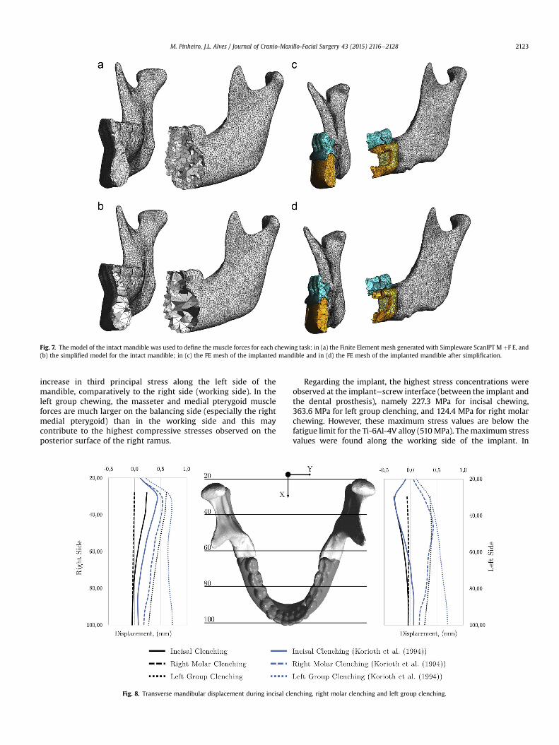
Fig. 7. The model of the intact mandible was used to define the muscle forces for each chewing task: in (a) the Finite Element mesh generated with Simpleware ScanIPT M þF E, and(b) the simplified model for the intact mandible; in (c) the FE mesh of the implanted mandible and in (d) the FE mesh of the implanted mandible after simplification.
M. Pinheiro, J.L. Alves / Journal of Cranio-Maxillo-Facial Surgery 43 (2015) 2116e2128 2123
increase in third principal stress along the left side of themandible, comparatively to the right side (working side). In theleft group chewing, the masseter and medial pterygoid muscleforces are much larger on the balancing side (especially the rightmedial pterygoid) than in the working side and this maycontribute to the highest compressive stresses observed on theposterior surface of the right ramus.
Fig. 8. Transverse mandibular displacement during incisal cle
Regarding the implant, the highest stress concentrations wereobserved at the implantescrew interface (between the implant andthe dental prosthesis), namely 227.3 MPa for incisal chewing,363.6 MPa for left group clenching, and 124.4 MPa for right molarchewing. However, these maximum stress values are below thefatigue limit for the Ti-6Al-4V alloy (510MPa). Themaximum stressvalues were found along the working side of the implant. In
nching, right molar clenching and left group clenching.
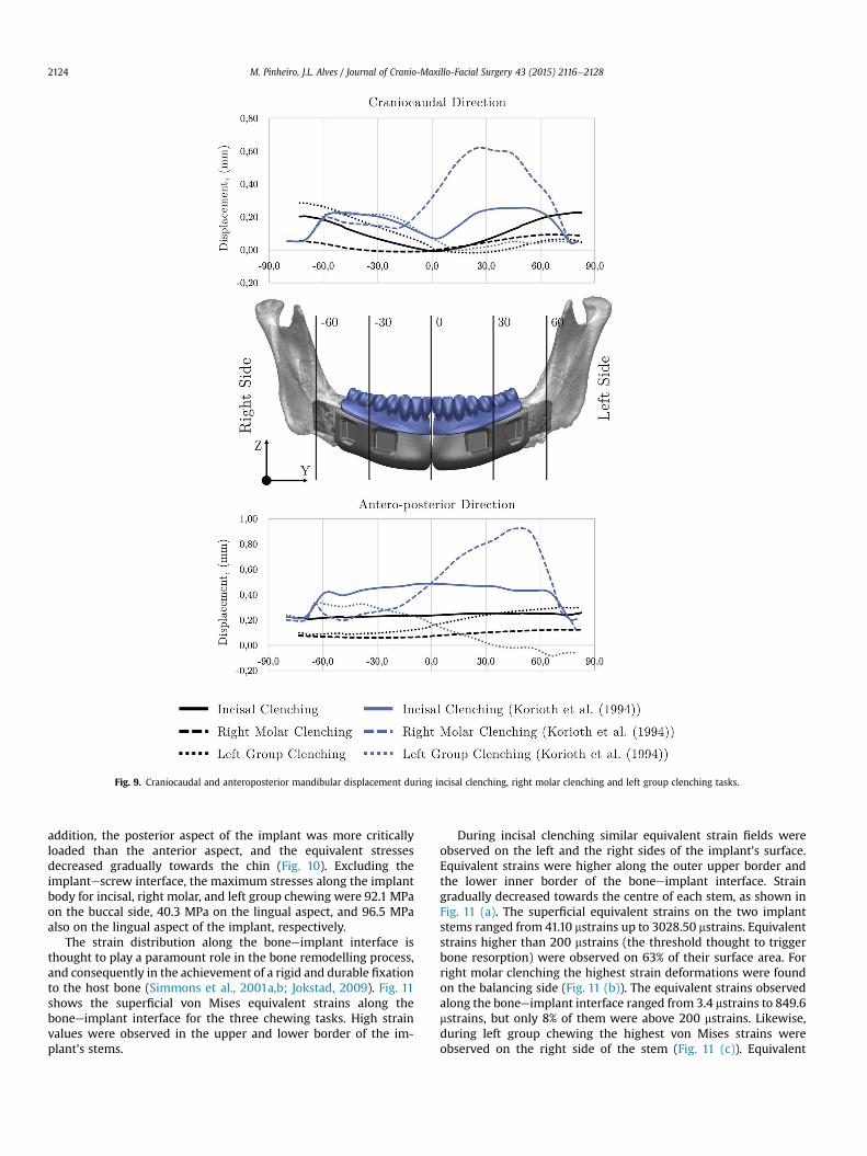
Fig. 9. Craniocaudal and anteroposterior mandibular displacement during incisal clenching, right molar clenching and left group clenching tasks.
M. Pinheiro, J.L. Alves / Journal of Cranio-Maxillo-Facial Surgery 43 (2015) 2116e21282124
addition, the posterior aspect of the implant was more criticallyloaded than the anterior aspect, and the equivalent stressesdecreased gradually towards the chin (Fig. 10). Excluding theimplantescrew interface, the maximum stresses along the implantbody for incisal, right molar, and left group chewing were 92.1 MPaon the buccal side, 40.3 MPa on the lingual aspect, and 96.5 MPaalso on the lingual aspect of the implant, respectively.
The strain distribution along the boneeimplant interface isthought to play a paramount role in the bone remodelling process,and consequently in the achievement of a rigid and durable fixationto the host bone (Simmons et al., 2001a,b; Jokstad, 2009). Fig. 11shows the superficial von Mises equivalent strains along theboneeimplant interface for the three chewing tasks. High strainvalues were observed in the upper and lower border of the im-plant's stems.
During incisal clenching similar equivalent strain fields wereobserved on the left and the right sides of the implant's surface.Equivalent strains were higher along the outer upper border andthe lower inner border of the boneeimplant interface. Straingradually decreased towards the centre of each stem, as shown inFig. 11 (a). The superficial equivalent strains on the two implantstems ranged from 41.10 mstrains up to 3028.50 mstrains. Equivalentstrains higher than 200 mstrains (the threshold thought to triggerbone resorption) were observed on 63% of their surface area. Forright molar clenching the highest strain deformations were foundon the balancing side (Fig. 11 (b)). The equivalent strains observedalong the boneeimplant interface ranged from 3.4 mstrains to 849.6mstrains, but only 8% of them were above 200 mstrains. Likewise,during left group chewing the highest von Mises strains wereobserved on the right side of the stem (Fig. 11 (c)). Equivalent
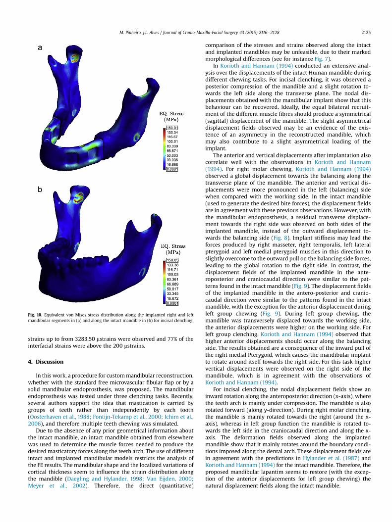
Fig. 10. Equivalent von Mises stress distribution along the implanted right and leftmandibular segments in (a) and along the intact mandible in (b) for incisal clenching.
M. Pinheiro, J.L. Alves / Journal of Cranio-Maxillo-Facial Surgery 43 (2015) 2116e2128 2125
strains up to from 3283.50 mstrains were observed and 77% of theinterfacial strains were above the 200 mstrains.
4. Discussion
In this work, a procedure for custommandibular reconstruction,whether with the standard free microvascular fibular flap or by asolid mandibular endoprosthesis, was proposed. The mandibularendoprosthesis was tested under three clenching tasks. Recently,several authors support the idea that mastication is carried bygroups of teeth rather than independently by each tooth(Oosterhaven et al., 1988; Fontijn-Tekamp et al., 2000; Ichim et al.,2006), and therefore multiple teeth chewing was simulated.
Due to the absence of any prior geometrical information aboutthe intact mandible, an intact mandible obtained from elsewherewas used to determine the muscle forces needed to produce thedesired masticatory forces along the teeth arch. The use of differentintact and implanted mandibular models restricts the analysis ofthe FE results. The mandibular shape and the localized variations ofcortical thickness seem to influence the strain distribution alongthe mandible (Daegling and Hylander, 1998; Van Eijden, 2000;Meyer et al., 2002). Therefore, the direct (quantitative)
comparison of the stresses and strains observed along the intactand implanted mandibles may be unfeasible, due to their markedmorphological differences (see for instance Fig. 7).
In Korioth and Hannam (1994) conducted an extensive anal-ysis over the displacements of the intact Human mandible duringdifferent chewing tasks. For incisal clenching, it was observed aposterior compression of the mandible and a slight rotation to-wards the left side along the transverse plane. The nodal dis-placements obtained with the mandibular implant show that thisbehaviour can be recovered. Ideally, the equal bilateral recruit-ment of the different muscle fibres should produce a symmetrical(sagittal) displacement of the mandible. The slight asymmetricaldisplacement fields observed may be an evidence of the exis-tence of an asymmetry in the reconstructed mandible, whichmay also contribute to a slight asymmetrical loading of theimplant.
The anterior and vertical displacements after implantation alsocorrelate well with the observations in Korioth and Hannam(1994). For right molar chewing, Korioth and Hannam (1994)observed a global displacement towards the balancing along thetransverse plane of the mandible. The anterior and vertical dis-placements were more pronounced in the left (balancing) sidewhen compared with the working side. In the intact mandible(used to generate the desired bite forces), the displacement fieldsare in agreement with these previous observations. However, withthe mandibular endoprosthesis, a residual transverse displace-ment towards the right side was observed on both sides of theimplanted mandible, instead of the outward displacement to-wards the balancing side (Fig. 8). Implant stiffness may lead theforces produced by right masseter, right temporalis, left lateralpterygoid and left medial pterygoid muscles in this direction toslightly overcome to the outward pull on the balancing side forces,leading to the global rotation to the right side. In contrast, thedisplacement fields of the implanted mandible in the ante-roposterior and craniocaudal direction were similar to the pat-terns found in the intact mandible (Fig. 9). The displacement fieldsof the implanted mandible in the antero-posterior and cranio-caudal direction were similar to the patterns found in the intactmandible, with the exception for the anterior displacement duringleft group chewing (Fig. 9). During left group chewing, themandible was transversely displaced towards the working side,the anterior displacements were higher on the working side. Forleft group clenching, Korioth and Hannam (1994) observed thathigher anterior displacements should occur along the balancingside. The results obtained are a consequence of the inward pull ofthe right medial Pterygoid, which causes the mandibular implantto rotate around itself towards the right side. For this task highervertical displacements were observed on the right side of themandibule, which is in agreement with the observations ofKorioth and Hannam (1994).
For incisal clenching, the nodal displacement fields show aninward rotation along the anteroposterior direction (x-axis), wherethe teeth arch is mainly under compression. The mandible is alsorotated forward (along y-direction). During right molar clenching,the mandible is mainly rotated towards the right (around the x-axis), whereas in left group function the mandible is rotated to-wards the left side in the craniocaudal direction and along the x-axis. The deformation fields observed along the implantedmandible show that it mainly rotates around the boundary condi-tions imposed along the dental arch. These displacement fields arein agreement with the predictions in Hylander et al. (1987) andKorioth and Hannam (1994) for the intact mandible. Therefore, theproposed mandibular lapantim seems to restore (with the excep-tion of the anterior displacements for left group chewing) thenatural displacement fields along the intact mandible.

Fig. 11. Equivalent strain deformation along the boneeimplant interface for incisal biting (a), right molar clenching (b), and left group biting (c).
M. Pinheiro, J.L. Alves / Journal of Cranio-Maxillo-Facial Surgery 43 (2015) 2116e21282126
Similar stress fields were observed for both intact and implantedmandibles (Fig. 10). This suggests that the proposed mandibularendoprosthesis allows the preservation of the normal stress dis-tribution along the right and left mandibular segments. In addition,the proposed solid mandibular endoprosthesis showed no signs ofmechanical failure, nor reduced stiffness as previously reported byother authors (Wong et al., 2012b). The results obtained show thatstress distributions in the mandible are complex, and slightlydifferent depending on the chewing task. In incisal clenching, stressconcentrations were observed mainly along the distal temporalcrest, the posterior aspect of the ascending ramus, the mandibularnotch, and in the lower and lingual surface of the mandibleimmediately anterior to the mandible angle. These stress fields areconsistent with the results obtained in Meyer et al. (2002) withphotoelastic analysis.
For unilateral clenching, high stress concentrations wereobserved on the ipsilateral temporal crest and contralateral prox-imal posterior ramus. Stress concentrations along mandibular bodyof the working side and posterior mandibular ramus of thebalancing side have been previously observed in Wang et al. (2010)for left unilateral chewing. The highest stresses along themandibular implant were also observed at the implantescrewinterface, nevertheless these stresses were always below the fa-tigue limit of the Ti-6Al-4V alloy considered for implantmanufacturing. In addition, the mandibular endoprosthesis alsoavoids using screwed connections that have been associated withunfavourable stress concentrations along the mandibular bone,implant loosening and implant and screw fracture by several au-thors (Kim and Donoff, 1992; Spencer et al., 1999; Shibahara et al.,2002; Knoll et al., 2006; Ramos et al., 2011; Narra et al., 2014).
M. Pinheiro, J.L. Alves / Journal of Cranio-Maxillo-Facial Surgery 43 (2015) 2116e2128 2127
The endoprosthesis concept was successfully applied in Lee et al.(2008) and in Goh et al., (2009b) for the reconstruction of themandibular body and unilateral reconstruction of the ascendingramus. In a histological evaluation of a cemented modularmandibular endoprosthesis 6 months after implantation, Lee et al.(2009) found no signs of loosening and the radiological evaluationrevealed a stable position of the implant. It was also observed anincrease of woven bone volume around the implant stems, partic-ularly along the inferior and lingual aspects of the implant stems. Inaddition, the histological evaluation of the endoprosthesis appliedto the ramus 3 and 6 month after implantation showed an overallincrease of the bone volume around the implant's stem (Goh et al.,2009a), and a residual bone mass density loss of 1.8%e5.8% wereobserved around the implant (Goh et al., 2010). Nearly completebone union and bone ingrowth were observed in Chanchareonsooket al. (2014) with an hydroxyapatite-coated custom modularendoprosthesis implanted in monkeys after 6 months follow-up.
In this work high strain values were observed not only on theinferior and lingual regions of the stems, but also on the buccal andsuperior aspects, especially on the balancing side during unilateralchewing. In addition, the strain deformations along the implantstems showed that 63% and 77% of the implantebone interfaceexperience strains above 200 mstrains during incisal and left groupclenching, which is thought to be the physiological threshold totrigger bone maintenance and remodelling. Nevertheless, a smallerand less stiff implant may be advantageous to reduced strainshielding around the implantebone interface. For dental prosthe-siseimplant interface, a four dental implant system was consid-ered. This system seems to be unsuitable for transmitting distalteeth chewing forces to the supporting bone. A different type ofimplantedental prosthesis interface, such as a solid interface or ascrewed interface with more distal screws should be considered inthe future, to improve bone loading during right molar loading(Fig. 11).
The results obtained for the mandibular endoprosthesis are veryencouraging. However, these results may be affected by the sim-plifications on the FE model. In this study, all materials in the FEmodel were assumed to be isotropic and homogeneous. Ichim et al.(2006) argued that modelling the Human mandible as an isotropicmaterial was sufficient to obtain meaningful physiological strainvariations during different chewing tasks. However, it is knownthat the Human mandible is more accurately modelled as ananisotropic (Ashman et al., 1984; Dechow et al., 1993), or a trans-versely isotropic material (Hart et al., 1992; Van Eijden, 2000), andthat it may be highly heterogeneous due to the variations of corticalthickness along the different anatomical regions (Daegling andHylander, 1998). The muscle insertion areas in the FE model arealso a simplification of the real insertion areas. For instance, themasseter muscles occupy almost all the lateral surface of theascending ramus. The high stress concentrations at the muscleinsertion sites and smaller stresses along the inner aspect of theramus (in both intact and implantedmandibles) may be unrealistic.
The implant and the bone are also assumed to be perfectlybounded. Immediately after insertion there is always a certainamount of relative movement between the two bodies. The exis-tence of micro-motions along the boneeimplant interface, at thisearly stage, may compromise bone ingrowth into the implant, andin the long term lead to implant loosening, particularly incementless designs such as the one proposed here. Interfacialmicro-motions above 150 mm seem to inhibit bone ingrowth intothe implant (Pilliar et al., 1986; Jasty et al., 1997). Hence, to predictmore reliably the behaviour of the mandibular endoprosthesis in-vivo, a more realist model may be needed. The implant is alsoclearly over-dimensioned and the reduction of the implant's stiff-ness may be important to obtain a more natural deformation of the
mandible, and promote a more favourable environment for implantosseointegration. Reducing the implant's cross-section to a simpletitanium core capable to sustain the different chewing tasks, andthe addition of other non-metallic features to obtain the desiredmandibular shape defined in the cephalometric assessment, or theaddition of other geometrical features to this design may bepossible solutions.
5. Conclusions
In this work a custom-made mandibular endoprosthesis tobridge a major mandibular defect is proposed. A cephalometricanalysis was applied to estimate the most plausible position of thechin along the sagittal plane. The geometrical and anatomical re-lations between the maxilla and the mandible, as well as the lowerarch teeth, were considered in the project phase in order to guar-antee the functional and aesthetic outcome of the mandibularreconstruction. The custom-made implant also aims to avoid theapplication of screws, since these features are commonly associatedwith unnatural stress fields along the mandible and with implantfailure.
The newly designed implant was validated with Finite ElementAnalysis under three clenching tasks, namely incisal, right molarand left group clenching. The implanted mandible showsdisplacement fields that are similar to the displacement patternsobserved for intact mandibles. The stress fields observed along thetwo mandibular segments also correlate well with the stress dis-tributions observed for the intact mandible. The strain values at theimplantebone interface may also promote bone preservation andingrowth around the implant. These preliminary results show thatthese implants may be a reliable alternative to other prostheticmandibular reconstruction approaches.
Conflict of interest statementThe authors declare that there are no conflicts of interest.
Acknowledgment
The first author would like to acknowledge FCT Fundaç~ao para aCiencia e Tecnologia (Portugal) for the PhD grant SFRH/BDE/51143/2010. The authors also would like to acknowledge MCM - Mario daCosta Martins& Filho Lda. for all technical support provided duringthis work.
References
Ashman R, Cowin S, Van Buskirk W, Rice J: A continuous wave technique for themeasurement of the elastic properties of cortical bone. J Biomech 17: 349e361,1984
Athanasiou AE: Orthodontic cephalometry. Mosby-Wolfe, 1995Baggi L, Cappelloni I, Di Girolamo M, Maceri F, Vairo G: The influence of implant
diameter and length on stress distribution of osseointegrated implants relatedto crestal bone geometry: a three- dimensional finite element analysis.J Prosthet Dent 100: 422e431, 2008
Bak M, Jacobson AS, Buchbinder D, Urken ML: Contemporary reconstruction of themandible. Oral Oncol 46: 71e76, 2010
Bozkaya D, Muftu S, Muftu A: Evaluation of load transfer characteristics of fivedifferent implants in compact bone at different load levels by finite elementsanalysis. J Prosthet Dent 92: 523e530, 2004
Chanchareonsook N, Tideman H, Feinberg SE, Jongpaiboonkit L, Lee S, Flanagan C,et al: Segmental mandibular bone reconstruction with a carbonate- substitutedhydroxyapatite-coated modular endoprosthetic poly (ε-caprolactone) scaffoldin macaca fascicularis. J Biomed Mater Res B Appl Biomater 102: 962e976, 2014
Cobourne M, DiBiase A: Handbook of orthodontics. Elsevier Health Sciences UK,2010
Daegling DJ, Hylander WL: Biomechanics of torsion in the human mandible. Am JPhys Anthropol 105: 73e88, 1998
Dechow P, Nail G, Schwartz-Dabney C, Ashman R: Elastic properties of humansupraorbital and mandibular bone. Am J Phys Anthropol 90: 291e306, 1993
M. Pinheiro, J.L. Alves / Journal of Cranio-Maxillo-Facial Surgery 43 (2015) 2116e21282128
Disa JJ, Cordeiro PG: Mandible reconstruction with microvascular surgery. In:Library WO (ed.), Semin Surg Oncol. Wiley Online Library, 226e234, 2000
Ferrario V, Sforza C, Serrao G, Dellavia C, Tartaglia G: Single tooth bite forces inhealthy young adults. J Oral Rehabil 31: 18e22, 2004
Ferri J, Piot B, Ruhin B, Mercier J: Advantages and limitations of the fibula free flapin mandibular reconstruction. J Oral Maxillofac Surg 55: 440e448, 1997
Flint P, Haughey B, Niparko J, Richardson M, Lund V, Robbins K, et al. Cummingsotolaryngology - head and neck surgery, 3-volume set, vol. 1. Elsevier HealthSciences, 2010
Fontijn-Tekamp F, Slagter A, Van Der Bilt A, Hof MV, Witter D, Kalk W, et al: Bitingand chewing in overdentures, full dentures, and natural dentitions. J Dent Res79: 1519e1524, 2000
Goh BT, Lee S, Tideman H, Jansen JA, Stoelinga PJ: Replacement of the condyle andascending ramus by a modular endoprosthesis in macaca fascicularis part 2:microcomputed tomographic and histologic evaluation of the ramus and stem.J Oral Maxillofac Surg 67: 2617e2626, 2009a
Goh BT, Lee S, Tideman H, Stoelinga PJ: Mandibular reconstruction in adults: areview. Int J Oral Maxillofac Surg 37: 597e605, 2008
Goh BT, Lee S, Tideman H, Stoelinga PJ: Replacement of the condyle and ascendingramus by a modular endoprosthesis in macaca fascicularis part 1: a clinical andradiographic study. J Oral Maxillofac Surg 67: 1392e1400, 2009b
Goh BT, Lee S, Tideman H, Stoelinga PJ, Jansen JA: Replacement of the condyle andascending ramus by a modular endoprosthesis in macaca fascicularis part 3:evaluation of peri-implant bone remodeling. J Oral Maxillofac Surg 68:1776e1782, 2010
Gurtner GC, Evans GR: Advances in head and neck reconstruction. J Oral MaxillofacSurg 106: 672e682, 2000
Hart RT, Hennebel VV, Thongpreda N, Van Buskirk WC, Anderson RC: Modeling thebiomechanics of the mandible: a three-dimensional finite element study.J Biomech 25: 261e286, 1992
Haughey BH, Fredrickson JM, Lerrick AJ, Sclaroff A, Gay WD: Fibular and iliac crestosteomuscular free flap reconstruction of the oral cavity. Laryngoscope 104:1305e1313, 1994
Hidalgo DA: Fibula free flap: a new method of mandible reconstruction. PlastReconstr Surg 84: 71e79, 1989
Hilgers ML, Scarfe WC, Scheetz JP, Farman AG: Accuracy of linear temporoman-dibular joint measurements with cone beam computed tomography and digitalcephalometric radiography. Am J Orthod Dentofacial Orthop 128: 803e811,2005
Hylander WL, Johnson KR, Crompton A: Loading patterns and jaw movementsduring mastication in macaca fascicularis: a bone-strain, electromyographic,and cineradiographic analysis. Am J Phys Anthropol 72: 287e314, 1987
Ichim I, Swain M, Kieser J: Mandibular biomechanics and development of the hu-man chin. J Dent Res 85: 638e642, 2006
Jackson J: A user's guide to principal components. Wiley, 2005 Wiley Series inProbability and Statistics
Jasty M, Bragdon C, Burke D, O'Connor D, Lowenstein J, Harris WH: In vivo skeletalresponses to porous-surfaced implants subjected to small induced motions.J Bone Joint Surg 79: 707e714, 1997
Jokstad A: Osseointegration and dental implants. John Wiley & Sons, 2009Kawashima S, Peltomaki T, Sakata H, Mori K, Happonen RP, Ronning O: Craniofacial
morphology in preschool children with sleep-related breathing disorder andhypertrophy of tonsils. Acta Paediatr 91: 71e77, 2002
Kim MR, Donoff RB: Critical analysis of mandibular reconstruction using aoreconstruction plates. J Oral Maxillofac Surg 50: 1152e1157, 1992
Knoll WD, Gaida A, Maurer P: Analysis of mechanical stress in reconstruction platesfor bridging mandibular angle defects. J Craniomaxillofac Surg 34: 201e209,2006
Korioth T, Hannam A: Deformation of the human mandible during simulated toothclenching. J Dent Res 73: 56e66, 1994
Lagrav�ere MO, Hansen L, Harzer W, Major PW: Plane orientation for standardizationin 3- dimensional cephalometric analysis with computerized tomography im-aging. Am J Orthod Dentofacial Orthop 129: 601e604, 2006
Lee S, Goh B, Tideman H, Stoelinga P: Modular endoprosthesis for mandibularreconstruction: a preliminary animal study. Int J Oral Maxillofac Surg 37:935e942, 2008
Lee S, Goh B, Tideman H, Stoelinga P, Jansen J: Modular endoprosthesis formandibular body reconstruction: a clinical, micro-ct and histologic evaluationin eight macaca fascicularis. Int J Oral Maxillofac Surg 38: 40e47, 2009
Li P, Shen L, Li J, Liang R, Tian W, Tang W: Optimal design of an individual endo-prosthesis for the reconstruction of extensive mandibular defects with finiteelement analysis. J Craniomaxillofac Surg 42: 73e78, 2014
Mal�o P, Rangert B, Nobre M: All-on-four immediate-function concept with Brane-mark system® implants for completely edentulous mandibles: a retrospectiveclinical study. Clin Implant Dent Relat Res 5: 2e9, 2003
Mal�o P, Rangert B, Nobre M: All-on-4 immediate-function concept with Branemarksystem® implants for completely edentulous maxillae: a 1-year retrospectiveclinical study. Clin Implant Dent Relat Res 7: s88es94, 2005
Meneghini F, Biondi P: Clinical facial analysis: elements, principles, and techniques.Springer Berlin Heidelberg, 2012
Meyer C, Kahn JL, Boutemi P, Wilk A: Photoelastic analysis of bone deformation inthe region of the mandibular condyle during mastication. J CraniomaxillofacSurg 30: 160e169, 2002
Miloro M, Ghali G, Larsen P, Waite P. Peterson's principles of oral and maxillofacialsurgery, vol. 1. B C Decker, 2004
Misch CE: Contemporary implant dentistry. Elsevier Health Sciences, 2007Mitchell L: An introduction to orthodontics. OUP Oxford, 2013Moorrees CF, Kean MR: Natural head position, a basic consideration in the inter-
pretation of cephalometric radiographs. Am J Phys Anthropol 16: 213e234, 1958Narra N, Val�a�sek J, Hannula M, Marci�an P, Sandor GK, Hyttinen J, et al: Finite
element analysis of customized reconstruction plates for mandibular continuitydefect therapy. J Biomech 47: 264e268, 2014
Nickels L: World's first patient-specific jaw implant. Metal Powder Rep 67: 12e14,2012
Oliveira M, Alves J, Menezes L: Algorithms and strategies for treatment of largedeformation frictional contact in the numerical simulation of deep drawingprocess. Arch Computational Methods Eng 15: 113e162, 2008
Oosterhaven SP, Westert GP, Schaub RM, Bilt A: Social and psychologic implicationsof missing teeth for chewing ability. Community Dent Oral Epidemiol 16:79e82, 1988
€Ostrup LT, Fredrickson JM: Reconstruction of mandibular defects after radiation,using a free, living bone graft transferred by microvascular anastomoses: anexperimental study. Plast Reconstr Surg 55: 563e572, 1975
Peckitt N: Stereoscopic lithography: customized titanium implants in orofacialreconstruction. Br J Oral Maxillofac Surg 37: 353e369, 1999
Peled M, El-Naaj IA, Lipin Y, Ardekian L: The use of free fibular flap for functionalmandibular reconstruction. J Oral Maxillofac Surg 63: 220e224, 2005
Pilliar R, Lee J, Maniatopoulos C: Observations on the effect of movement on boneingrowth into porous-surfaced implants. Clin Orthop Relat Res 208: 108e113,1986
Pinheiro M, Alves J: A new level-set based protocol for accurate bone segmentationfrom ct imaging, http://arxiv.org/abs/1505.03093; Submitted
Proffit W, Fields H, Sarver D: Contemporary orthodontics. Elsevier Health Sciences,2006
Ramos A, Completo A, Relvas C, Mesnard M, Simeoes J: Straight, semi-anatomic andanatomic TMJ implants: the influence of condylar geometry and bone fixationscrews. J Craniomaxillofac Surg 39: 343e350, 2011
Samman N, Luck W, Cheung L, Tideman H, Clark R: Custom-made titaniummandibular reconstruction tray. Aust Dent J 44: 195e199, 1999
Sato K, Shirakawa T, Sakata H, Asanuma S: Effectiveness of the analysis of cranio-facial morphology and pharyngeal airway morphology in the treatment ofchildren with obstructive sleep apnoea syndrome. Dentomaxillofac Radiol 41:411e416, 2012
Shibahara T, Noma H, Furuya Y, Takaki R: Fracture of mandibular reconstructionplates used after tumor resection. J Oral Maxillofac Surg 60: 182e185, 2002
Simmons CA, Meguid SA, Pilliar RM: Differences in osseointegration rate due toimplant surface geometry can be explained by local tissue strains. J Orthop Res19: 187e194, 2001a
Simmons CA, Meguid SA, Pilliar RM: Mechanical regulation of localized andappositional bone formation around bone-interfacing implants. J Biomed MaterRes 55: 63e71, 2001b
Singare S, Dichen L, Bingheng L, Yanpu L, Zhenyu G, Yaxiong L: Design and fabri-cation of custom mandible titanium tray based on rapid prototyping. Med EngPhys 26: 671e676, 2004
Singh G: Textbook of orthodontics. G e reference, information and interdisciplinarysubjects series. Jaypee Brothers, Medical Publishers, 2008
Skedros J, Mason M, Nelson M, Bloebaum R: Evidence of structural and materialadaptation to specific strain features in cortical bone. Anat Rec 246: 47e63,1996
Spencer K, Sizeland A, Taylor G, Wiesenfeld D: The use of titanium mandibularreconstruction plates in patients with oral cancer. Int J Oral Maxillofac Surg 28:288e290, 1999
Taylor GI: Reconstruction of the mandible with free composite iliac bone grafts. AnnPlast Surg 9: 361e376, 1982
Tideman H, Lee S: The TL endoprosthesis for mandibular reconstruction a metallicyet biological approach. J Oral Maxillofac Surg Med Pathol 18, 2006
Van Eijden T: Biomechanics of the mandible. Crit Rev Oral Biol Med 11: 123e136,2000
Van Oosterwyck H, Duyck J, Vander Sloten J, Van der Perre G, De Coomans M,Lieven S, et al: The influence of bone mechanical properties and implant fixa-tion upon bone loading around oral implants. Clin Oral Implant. Res 9: 407e418,1998
Waltimo A, Kemppainen P, K€ononen M: Maximal contraction force and enduranceof human jaw-closing muscles in isometric clenching. Eur J Oral Sci 101:416e421, 1993
Wang H, Ji B, Jiang W, Liu L, Zhang P, Tang W, et al: Three-dimensional finiteelement analysis of mechanical stress in symphyseal fractured human mandiblereduced with miniplates during mastication. J Oral Maxillofac Surg 68:1585e1592, 2010
Welsch G, Boyer R, Collings E: Materials properties handbook: titanium alloys. ASMInternational, 1993
Wong RC, Tideman H, Merkx MA, Jansen J, Goh SM: The modular endoprosthesis formandibular body replacement. Part 1: mechanical testing of the reconstruction.J Craniomaxillofac Surg 40: 479e486, 2012a
Wong RC, Tideman H, Merkx MA, Jansen J, Goh SM: The modular endoprosthesis formandibular body replacement. Part 2: finite element analysis of endoprosthesisreconstruction of the mandible. J Craniomaxillofac Surg 40: 487e497, 2012b
Y�a~nez-Vico RM, Iglesias-Linares A, Torres-Lagares D, Guti�errez-P�erez JL, Sol-ano-Reina E: Three-dimensional evaluation of craniofacial asymmetry: ananalysis using computed tomography. Clin Oral Investig 15: 729e736,2011