Journal of Composite Materials - University of California...
12
http://jcm.sagepub.com Journal of Composite Materials DOI: 10.1177/0021998307075444 2007; 41; 2313 originally published online Jul 2, 2007; Journal of Composite Materials Yabei Gu and Vitali F. Nesterenko Design and Ballistic Testing of Ti6Al4V Matrix Composites http://jcm.sagepub.com/cgi/content/abstract/41/19/2313 The online version of this article can be found at: Published by: http://www.sagepublications.com On behalf of: American Society for Composites can be found at: Journal of Composite Materials Additional services and information for http://jcm.sagepub.com/cgi/alerts Email Alerts: http://jcm.sagepub.com/subscriptions Subscriptions: http://www.sagepub.com/journalsReprints.nav Reprints: http://www.sagepub.com/journalsPermissions.nav Permissions: © 2007 SAGE Publications. All rights reserved. Not for commercial use or unauthorized distribution. at UNIV CALIFORNIA SAN DIEGO on February 1, 2008 http://jcm.sagepub.com Downloaded from
Transcript of Journal of Composite Materials - University of California...

http://jcm.sagepub.com
Journal of Composite Materials
DOI: 10.1177/0021998307075444 2007; 41; 2313 originally published online Jul 2, 2007; Journal of Composite Materials
Yabei Gu and Vitali F. Nesterenko Design and Ballistic Testing of Ti�6Al�4V Matrix Composites
http://jcm.sagepub.com/cgi/content/abstract/41/19/2313 The online version of this article can be found at:
Published by:
http://www.sagepublications.com
On behalf of: American Society for Composites
can be found at:Journal of Composite Materials Additional services and information for
http://jcm.sagepub.com/cgi/alerts Email Alerts:
http://jcm.sagepub.com/subscriptions Subscriptions:
http://www.sagepub.com/journalsReprints.navReprints:
http://www.sagepub.com/journalsPermissions.navPermissions:
© 2007 SAGE Publications. All rights reserved. Not for commercial use or unauthorized distribution. at UNIV CALIFORNIA SAN DIEGO on February 1, 2008 http://jcm.sagepub.comDownloaded from

Design and Ballistic Testing of Ti–6Al–4VMatrix Composites
YABEI GU*Graduate Aeronautical Laboratories, California Institute of Technology
1200E California Blvd, Mail Code 205-45, Pasadena, CA 91125, USA
VITALI F. NESTERENKO
Department of MAE, University of California San Diego
9500, Gilman Dr. La Jolla, CA 92093, USA
ABSTRACT: Ti–6Al–4V matrix composites enhanced by alumina tubes filled withboron carbide, alumina rods, and alumina plate is termed high gradient compositebecause of the big density differences among Ti–6Al–4V, alumina, and boron carbidematerials. This high gradient composite has been developed for a theoretical study tohelp determine the best configuration for armor protection. This is the first attemptwhere materials are prepared using a powder processing method with the specificgoal to address the ballistic performance. Hot isostatic pressing (HIP) was first usedto manufacture ballistic grade Ti–6Al–4V alloy and high gradient compositesincorporating Al2O3 rods, plates, and tubes filled with B4C powders. Processingparameters were investigated and optimized based on materials properties. Animportant feature of powder-based materials is the lack of texture in comparisonwith traditional material. Several configurations of this high gradient composite weredesigned and tested by long rod penetration tests. High gradient composite materialsdemonstrated new damage patterning features during the long rod projectilepenetration process. These features include projectile deflection, self-sealing of thehole, and forced shear localization in the direction of 45� to the impact line caused byfracture of Al2O3 tubes on the initial stage of penetration process. Powder filledvoids and rods induced volume distributed, highly heterogeneous pattern of damageinitiated by cavities and their interactions. The test results are shown and analyzed indepth in this paper. The results prove that the powder-based approach can be usedfor processing of materials suitable for ballistic applications.
KEY WORDS: hot isostatic press (HIP), Ti–6Al–4V matrix composites, shearlocalization, long rod projectile testing.
*Author to whom correspondence should be addressed. E-mail: [email protected] 7 and 8 appear in color online: http://jcm.sagepub.com
Journal of COMPOSITE MATERIALS, Vol. 41, No. 19/2007 2313
0021-9983/07/19 2313–11 $10.00/0 DOI: 10.1177/0021998307075444� SAGE Publications 2007
Los Angeles, London, New Delhi and Singapore
© 2007 SAGE Publications. All rights reserved. Not for commercial use or unauthorized distribution. at UNIV CALIFORNIA SAN DIEGO on February 1, 2008 http://jcm.sagepub.comDownloaded from
INTRODUCTION
TITANIUM AND TITANIUM alloys are the design choice for aerospace, biomedical, andother applications because of an attractive combination of low density, high strength,
ductility, high corrosion resistance, and biocompatibility. Hot isostatic pressing (HIP) isone of the most efficient techniques to develop high quality materials from the powders.This is the first attempt where materials are prepared using powder processing methodwith the specific goal to address the ballistic performance and high strain rate behavior.The results of the long rod projectile penetration test with tungsten (93%) heavy alloypenetrator on porous composite samples are presented. The fracture mechanisms underlong rod impact are different in comparison with conical and blunt projectiles. Theprevious works on conical and blunt projectile tests were included in the previouspublications [1–6]. Composite materials with alumina rods and tubes filled with B4Cpowders demonstrate new features of penetration: projectile deflection with self-sealingholes and built-in mechanism of forced shear localization caused by the tube’s fractureduring the initial stages of penetration. The high gradient composites are able to deflectthe projectile at the beginning of penetration. Powder filled voids and rods inducedvolume distributed, highly heterogeneous pattern of damage initiated by cavities and theirinteractions.
PROCESSING OF HIGH GRADIENT COMPOSITE
Porous composites are called high gradient in our case because their components havequite different densities. Particularly, Ti–6Al–4V matrix has a density of 4.46 g/cm3, solidalumina in the rod and in the wall of the tubes has a density of 3.9 g/cm3, and B4C powderinside the tube has a density of 1.18 g/cm3. Another important feature of this material isthe large scale of components (alumina rods, tubes comparable with the projectilediameter). The high-gradient composite materials are intended to deflect projectile at theearly stages of penetration, and to activate ‘horizontal’ damage. This may preventpenetration, and introduce new channels of energy dissipation like bulk fracture of thetarget and projectile and comminuting of covalent ceramics in cavities. Another goal is thereplacement of vertical shear banding resulting in easy plug formation by inclined andkinked shear banding. The main purpose of introducing powder filled voids and rods is toreplace dominant shear bands running in the direction parallel to impact by complex,volume distributed, highly heterogeneous pattern of damage initiated by cavities andtheir interaction.
Composite samples with different configurations were prepared using Al2O3 rods,Al2O3 tubes (Coors AD995) filled with B4C powders. Al2O3 disks (Coors AD998) werealso introduced. The rods (4.75mm diameter) and tubes (outer and inner diametersare 4.75 and 3.175mm) were placed into lattice with distances from the center in thehorizontal and vertical directions equal to 10 and 5mm, respectively (rod–tube–tube (RTT), Figure 1). In Figures 1–3, only the configurations of the Al2O3 rodand Al2O3 tubes are shown with the Ti support. The assembled Al2O3 rods andthe Al2O3 tubes will be placed into the matrix materials which is Ti–6Al–4V powder.The matrix material is not shown in Figures 1–3. CP Ti plate was introduced only as aconstruction support for the rod and the tubes during the assembly process. The Al2O3
rods and the Al2O3 tubes are sitting inside the matrix materials and there
2314 Y. GU AND V. F. NESTERENKO
© 2007 SAGE Publications. All rights reserved. Not for commercial use or unauthorized distribution. at UNIV CALIFORNIA SAN DIEGO on February 1, 2008 http://jcm.sagepub.comDownloaded from

Al2O3
Ti plates
5mm
5mm
5mm
Figure 1. First configuration of HIPed composite samples (RTT).
31mm 31mm
5mm5mm
5mm 5mm
5mm5mm
4mm 4mm
Figure 2. Different configurations of HIPed composite samples (TTP and RTP).
Al2O3 tubes
Al2O3Ti plate
Ti plate
Figure 3. Configurations of HIPed angled tubes composite samples. The glass capsule is not drawn inthis figure.
Design and Ballistic Testing of Ti–6Al–4V Matrix Composites 2315
© 2007 SAGE Publications. All rights reserved. Not for commercial use or unauthorized distribution. at UNIV CALIFORNIA SAN DIEGO on February 1, 2008 http://jcm.sagepub.comDownloaded from

are no empty gaps among them except the area inside the tubes which is filled byporous B4C.
Two titanium plates were used to hold the Al2O3 rods and tubes inside the tappedTi–6Al–4V powders. A punching die with perfect holes that have a slightly larger diameterwas machined in order to achieve the exact position of our configurations. The tubes orrods were all introduced into the holes punched on the titanium plates before placementinto the glass capsule. The non-milled powders were poured into the glass capsule duringthe process of assembly to hold the plates, rods, and tubes steady.
In the other two configurations (tube–tube–plate (TTP) and rod–tube–plate (RTP),Figure 2), two stacked Al2O3 plates (31mm diameter and 2mm thickness each) were alsoplaced at the bottom of the composite samples. These plates were placed first beforeintroducing two rows of Al2O3 rods and tubes above them.
For the angled tube composite (Figure 3), a 45� angle bent titanium plate was put onthe top of the Al2O3 plate (31mm diameter and 2mm thickness) in the first step. PREPnon-milled (PNM) powder was poured into the glass capsule, which is not shown in thefigure, and covered the Al2O3 plates making them stable. The Al2O3 tubes (3 and 1.5 cm)were inserted (45� angle) into the pre-punched holes on the angled surface of the titaniumplate and sit on the surface of the Al2O3 plates after pouring prep non-milled powders.The powder that we poured first made it easy to insert the tubes into the systems withoutsliding along the holes.
BALLISTIC EXPERIMENTAL RESULTS AND DISCUSSION
Set-up for long rod projectile testing on hot isostatically pressed (HIPed) materials areshown in Figure 4.
The samples (diameter 40mm and thickness 30mm) were shrink fitted into plates ofalloy MIL-T-9047G. The samples from baseline material were taken from a 2-inch rod ofMIL-T-9047G (�Yj"¼0:02 ¼ 979MPa, tensile strength 1055MPa and elongation 15%).Penetrators from tungsten (93%W) heavy alloy with L/D¼ 10 (mass 16.8 g, diameter4.93mm) were launched using the 20mm smooth bore powder gun at the University ofDayton Research Institute (UDRI). The inclination (pitch and yaw) of a projectile ismeasured prior to impact with the flash X-ray system and a fiducial set-up similar to thatdescribed in an article by Rupert and Grace [7]. Velocity, pitch, and yaw for each testare presented in Table 1. These characteristics are especially important for long rodprojectiles to ensure that differences in ballistic performance are due to the differencesin materials properties. The definitions for pitch and yaw are taken from a paper writtenby Goldsmith [1,8] (Figure 5).
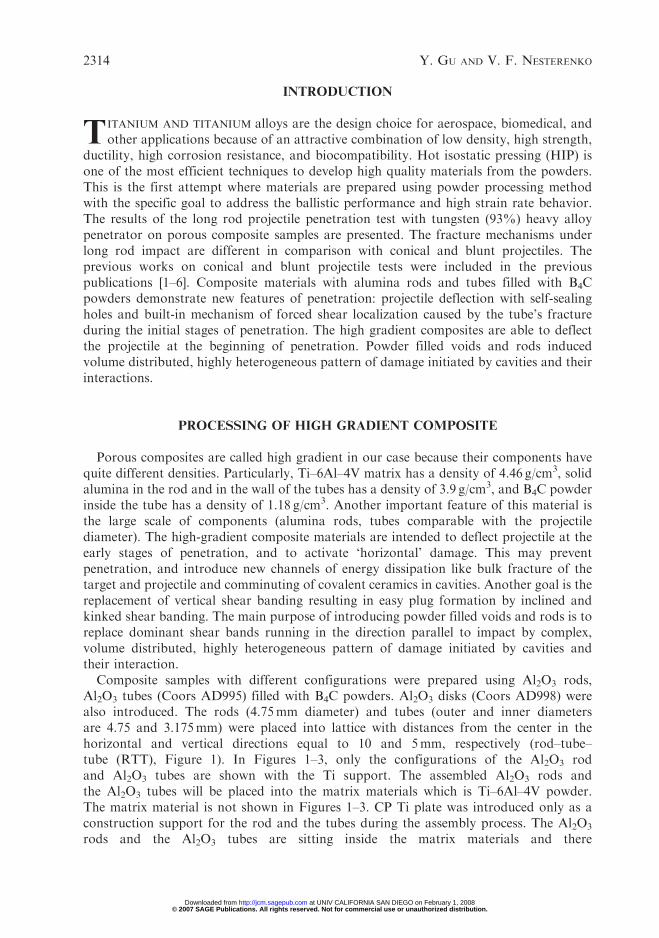
The samples after ballistic tests were cut normal to the orientation of the embeddedAl2O3 tubes or rods using Electrical Discharge Machining (EDM) or the diamond wiresaw. If rod and tubes were placed far away from the impacted side they practically did notparticipate in defeat of the projectile (Figure 6).
This composite had the Al2O3 rods closer to the surface of the impact at about 7.5mmfrom the surface and 10mm from the surface to the center of the Al2O3 rods. A newfeature was observed in this case. The projectile sealed the crater with heavily deformedremnants of the projectile (Figures 7 and 8). The geometry of rows of rods and poroustubes caused sever deformation of the penetrator and also changed the penetrator path(Figures 7 and 8).
2316 Y. GU AND V. F. NESTERENKO
© 2007 SAGE Publications. All rights reserved. Not for commercial use or unauthorized distribution. at UNIV CALIFORNIA SAN DIEGO on February 1, 2008 http://jcm.sagepub.comDownloaded from

30mm
30mm BACK PLATE (MIL-T-9047G Ti-6Al-4V)
150mm diameter
Impact velocity = 1000 m/s
4.98mm
49.8mm(L/D = 10)
MIL-T-904GTi-6Al-4V
Figure 4. Experimental set-up for long rod projectile penetration testing of high gradient composite materials.
Table 1. Experimental data for long rod penetration tests.
No. Materials Impact velocity (m/s) Pitch (�) Yaw (�)
10469 Composite (RTT) 971 0.5 110470 Composite (RTT) 976 0.5 2.51-515 Composite (RTP) 1086 – –1-516 Composite (TTP) 917 – –1-517 Composite (Angled) 947 – –1-518 Composite (Angled) 1250 – –
Z
x
a b
Z ′
q
Figure 5. Definition of the yaw angle �, pitch angle � and trajectory angle �.
Design and Ballistic Testing of Ti–6Al–4V Matrix Composites 2317
© 2007 SAGE Publications. All rights reserved. Not for commercial use or unauthorized distribution. at UNIV CALIFORNIA SAN DIEGO on February 1, 2008 http://jcm.sagepub.comDownloaded from
The TTP and RTP configurations with addition of alumina plates were introduced inorder to stop the projectile from penetration further into the target and to deflect theprojectile (Figure 9).
It is interesting that the forced shear localization from the collapse of alumina tubescaused shearing even in the alumina rods (left figure in Figure 9). Rotation of penetratordue to inclined forced shear is evident on the right figure in Figure 9. Forced shearlocalization due to the collapse of alumina tubes is evident for both cases. As a result ofside motion of the projectile induced by the built-in mechanism of shear localization,the penetrator is trapped inside the target reducing momentum transferred in comparisonwith homogeneous samples.
Figure 6. Experiment with no deflection of the tungsten long rod projectile, test 10469.
Figure 7. Deflection of the tungsten projectile in test 10470.
2318 Y. GU AND V. F. NESTERENKO
© 2007 SAGE Publications. All rights reserved. Not for commercial use or unauthorized distribution. at UNIV CALIFORNIA SAN DIEGO on February 1, 2008 http://jcm.sagepub.comDownloaded from

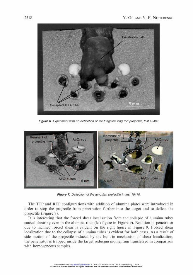
The last configuration that we introduced is inclined alumina tubes with an aluminaplate placed at the bottom. The purpose of introducing this geometry is to look at theprojectile interaction with the inclined ceramic parts and to investigate how forced shearlocalization will be generated in this case. It was also expected that inclined tubes will‘channel’ the projectile away from the impact line.
From Figure 10, we can see that, unfortunately, the penetrator went more or lessstraight into the samples, quite a different scenario in comparison with previousgeometries (Figure 7). The penetration depth is relatively large and the alumina tubesencountered during the penetration were destroyed. There was still some forced shearlocalization due to the interaction between the penetrator and the alumina tubes, butthe orientation of these shear bands does not follow 45� and practically follows the
Densified B4C powder Forced shear localization in Ti–6Al–4V matrix
Figure 8. Forced shear localization in Ti–6Al–4V based high gradient composite caused by fracture ofalumina tubes.
Figure 9. Tested RTP (rod–tube–plate). composites (left). Rotation of projectile is induced by built-inmechanism of shear localization (test 1-515) and tested TTP (tube–tube–plate) composites (right). Sidemotion of projectile is induced by built-in mechanism of shear localization (test 1-516).
Design and Ballistic Testing of Ti–6Al–4V Matrix Composites 2319
© 2007 SAGE Publications. All rights reserved. Not for commercial use or unauthorized distribution. at UNIV CALIFORNIA SAN DIEGO on February 1, 2008 http://jcm.sagepub.comDownloaded from
penetration direction. In the left figure in Figure 10, one of the alumina tubes at the leftside did not participate in the defeat, and did not generate forced shear localization despitebeing in the vicinity of entrance hole. The penetrator was shifted a little bit to one side andthe entire body of penetrator sealed the entrance hole with a thickness about 25mm deep.In the right figure, similar phenomena are also observed. But in this case the difference isthat penetrator is broken into pieces in comparison with the case presented in the leftfigure in Figure 10. Penetrators do not follow the direction of inclined tubes.
In general angled configuration was less efficient in generating forced shear localizationand projectile deflection in comparison with horizontal position of rods and tubes.
For high gradient composites, the significant difference from the homogeneousmaterials is that the fracture of the rods and tubes creates a larger volume involved ininteraction with the projectile (Figure 7). In addition, the forced shear bands initialed byfracture of Al2O3 tubes in the direction about 45� to impact line accompanied spontaneousshear bands resulting from instability of matrix materials. The shear bands are clearlytransgranular (Figure 11).
The chemical component in the diffusion layer in interfacial layer between Al2O3/Ti–6Al–4V was found to be Ti3Al by EDX. Ti3Al is a brittle phase and causes crack underthe ballistic testing in the interfacial layer. Figure 12 shows the characteristics of all thosecracks that developed after the testing.
All the small cracks that were developed because of impact are at rest inside thereactive layer and very rarely develop further into the Ti–6Al–4V matrix. Those crackswere developed because the reactive layer is comparatively brittle in comparison with
Figure 10. Angled composites after ballistic test (tests 1-517 and 1-518).
2320 Y. GU AND V. F. NESTERENKO
© 2007 SAGE Publications. All rights reserved. Not for commercial use or unauthorized distribution. at UNIV CALIFORNIA SAN DIEGO on February 1, 2008 http://jcm.sagepub.comDownloaded from

FracturedAl2O3 tubes
Forced shear localization
Impact direction
1000µm
Figure 11. Shear localization developed in Ti–6Al–4V matrix.
Figure 12. Local cracks in reactive layer.
Design and Ballistic Testing of Ti–6Al–4V Matrix Composites 2321
© 2007 SAGE Publications. All rights reserved. Not for commercial use or unauthorized distribution. at UNIV CALIFORNIA SAN DIEGO on February 1, 2008 http://jcm.sagepub.comDownloaded from

matrix material. Therefore, these small cracks do not have much effect on the overallproperties of the high gradient composite.
In comparison with the homogeneous materials, the damaged volume participatingin projectile deflection is relatively large. The localized plastic deformation of the tungstenprojectile is a characteristic feature of the process (Figure 13). While the remnants of theprojectile close to the entrance hole remained practically undeformed, extensive plasticdeformation of the bended parts of the projectile is an additional source of the energydissipation. Also, the energy absorption mechanism that is expected to be operative incomposites is the comminution of the ceramic materials B4C powder and the fracture ofAl2O3 rods and tubes.
CONCLUSION
High-gradient composite samples with B4C powder filled Al2O3 tubes suitable forballistic tests were successfully processed. Main fracture mode of Ti–6Al–4V HIPed solidmaterial is transgranular localization with subsequent crack formation. No cracking alonggrain boundaries was observed for the tests. Composite high-gradient sample demon-strated a capability to change a penetration path of long-rod penetrator and introducednew qualitative features of damage pattern, like forced shear localization in Ti–6Al–4Vmatrix under angle 45� to penetration path.
The main result of test with composite material shown in Figure 7 is that the projectilewas deflected by the rows of rods and tubes. Heavily deformed remnants of the projectilecompletely sealed the crater in test 10470 where Al2O3 rods were close to the impactsurface. In test 10469 with the larger distance of rods from the surface the entrancediameter of the hole was similar to the experiments with homogeneous HIPed samples
Figure 13. Plastic deformation of tungsten projectile.
2322 Y. GU AND V. F. NESTERENKO
© 2007 SAGE Publications. All rights reserved. Not for commercial use or unauthorized distribution. at UNIV CALIFORNIA SAN DIEGO on February 1, 2008 http://jcm.sagepub.comDownloaded from
(see References 2–6). This suggests that large entrance holes in homogeneous HIPedmaterials can be caused by target-induced yaw on the last stages of penetration. Inaddition to spontaneous shear bands resulting from instability of matrix material, the‘‘forced’’ shear bands initiated by fracture of Al2O3 tubes were also present (Figure 11).These shear bands are clearly transgranular. Interface layer on the boundary betweenAl2O3 tubes and matrix during the penetration had multiple cracks that were arrested bymatrix material (Figure 12).
High gradient composite materials can deflect long rod penetrator in optimizedgeometry and qualitatively change the fracture pattern of the target.
ACKNOWLEDGMENT
The support provided by the ARO, MURI DAAH 04-96-1-0376 is highly appreciated.
REFERENCES
1. Goldsmith, W. (1999). Non Ideal Projectile Impact on Targets, International Journal of ImpactEngineering, 22(2–3): 95–395.
2. Nesterenko, V.F., Indrakanti, S.S., Goldsmith, W. and Gu, Y. (2001). Plug Formation andFracture of Hot Isostatically Pressed (HIPed) Ti–6Al–4V Targets, In: Staudhammer, K.P., Murr,L.E. and Meyers, M.A. (eds), Fundamental Issues and Applications of Shock-Wave and High-Strain-Rate Phenomena, pp. 593–600, Elsevier Science, Amsterdam.
3. Nesterenko, V.F., Indrakanti, S.S., Brar, S. and Gu, Y. (2000). Long Rod Penetration Testof Hot Isostatically Pressed Ti-based Targets, Shock Compression of Condensed Matter, AIPConference Proceedings, 505(1): 419–422.
4. Nesterenko, V.F., Indrakanti, S.S., Brar, S. and Gu, Y. (2000). Ballistic Performance of HotIsostatically Pressed (HIPed) Ti-based Alloys, Key Engng. Mater., 177–180: 243–248.
5. Nesterenko, V.F., Goldsmith, W., Indrakanti, S.S. and Gu, Y. (2003). Response of HotIsostatically Pressed Ti–6Al–4V Targets to Normal Impact by Conical and Blunt Projectiles,International Journal of Impact Engineering, 28(2): 137–160.
6. Gu, Y., Indrakanti, S.S. and Nesterenko, V.F. (2002). Ballistic Testing and High-strain-rateProperties of Hot Isostatically Pressed Ti–6Al–4V, Shock Compression of Condensed Matter,AIP Conference Proceedings, 620(1): 1294–1297.
7. Rupert, N.L. and Grace, F.I. (1995). Impact Studies of Rod Projectiles Against Titanium andSteel Targets, In: Murr, L.E., Staudhammer, K.P., and Meyers, M.A. (eds), Metallurgical andMaterials Applications of Shock-Wave and High-Strain-rate Phenomena, pp. 257–264, ElsevierScience B.V., Amsterdam.
8. Goldsmith, W. (2001). Impact: The Theory and Physical Behavior of Colliding Solids, DoverPublications, Inc., Mineola, New York.
Design and Ballistic Testing of Ti–6Al–4V Matrix Composites 2323
© 2007 SAGE Publications. All rights reserved. Not for commercial use or unauthorized distribution. at UNIV CALIFORNIA SAN DIEGO on February 1, 2008 http://jcm.sagepub.comDownloaded from