Journal of Alloys and Compounds - University of South Florida
6
Preparation of Cu–Al 2 O 3 bulk nano-composites by combining Cu–Al alloy sheets internal oxidation with hot extrusion Fengzhang Ren a,b,⇑ , Aijuan Zhi c , Danwen Zhang a , Baohong Tian a , Alex A. Volinsky d , Xiaoni Shen a a School of Materials Science and Engineering, Henan University of Science and Technology, Luoyang 471023, China b Henan Collaborative Innovation Centre of Non-Ferrous Generic Technology, Luoyang 471023, China c College of Information Technology, Luoyang Normal University, Luoyang 471022, China d Department of Mechanical Engineering, University of South Florida, Tampa, FL 33620, USA article info Article history: Received 16 November 2014 Received in revised form 22 January 2015 Accepted 6 February 2015 Available online 14 February 2015 Keywords: Cu–Al 2 O 3 nano-composites Bulk materials Internal oxidation Hot extrusion Microstructure Properties abstract Cu–Al 2 O 3 bulk nano-composites were prepared by combining Cu–Al alloy sheets internal oxidation with hot extrusion. Cu–0.16 wt.%Al alloy sheets, 90 mm in diameter and 0.5 mm thick were internally oxidized with Cu 2 O + Cu + Al 2 O 3 mixed powders at 900 °C for 8 h. Nano-sized Al 2 O 3 particles were distributed in the Cu matrix with a coherent interface. The orientation relationship between the Cu matrix and the Al 2 O 3 particle was [2 1 1] Cu //[ 1 1 0] Al2O3 , (0 2 2) Cu //(2 2 0) Al2O3 and (1 1 1) Cu //(0 0 2) Al2O3 . Oxidized sheets were cleaned, stacked, vacuum sealed and hot extruded at 800 °C to prepare Cu–Al 2 O 3 nano-composite rods with a 20 mm diameter. The Cu–Al 2 O 3 rods were cold drawn to a wire with a diameter of 3 mm. The hot extruded rod and the cold drawn wire cross-sections presented concentric rings features, resem- bling tree rings. In the rings structure, the closer to the edge of the rod or the wire, the thinner the Cu–Al 2 O 3 sheets were with better interfacial bonding. The electrical conductivity of the rod was 96.3% IACS (International Annealed Copper Standard). The electrical conductivity, yield strength, tensile strength and reduction of the cross-sectional area of the drawn wire were 94.1%IACS, 417 MPa, 445 MPa and 80.2%, respectively. The paper demonstrates a feasible way to prepare Cu–Al 2 O 3 bulk nano-composites. Ó 2015 Elsevier B.V. All rights reserved. 1. Introduction Dispersion strengthened copper alloy is a kind of copper matrix composite made by introducing fine dispersion particles as the strengthening phase in the copper matrix [1,2]. Due to the high thermal and electrical conductivity, along with high strength and excellent high temperature resistance, these materials have become a research focus in the field of copper matrix composites [3–5]. Currently, the internal oxidation is a popular method to pre- pare the dispersion strengthened copper alloys with more homo- geneous microstructure. It can be further divided into powder internal oxidation and layer internal oxidation methods [6]. The common procedure of the powder internal oxidation is as follows: Preparation of the copper-based solid solution alloy pow- der ? mixing the alloy and oxidizer powders ? internal oxida- tion ? deoxidizing treatment ? mold pressing ? sintering process ? plastic deformation [7]. The powder internal oxidation method requires powder atomizing and vacuum sintering equip- ment [8–10], resulting in high equipment cost, only suitable for the high volume production. During the layer internal oxidation process a sheet or a rod of the copper-based solid solution alloy is packed in the oxidizer and then heated for internal oxidation. This process results in the formation of the dispersion strengthened copper alloy layer near the surface of a sheet or a rod (for a sheet, it can be fully oxidized) [11,12]. The layer internal oxidation can be easily achieved and does not require expensive equipment. However, at present it is only applied to prepare thin layers of the dispersion strengthened copper alloy. It is most commonly used to prepare thin sheets of the dispersion strengthened copper alloy, since the solid solution alloy sheet can be fully oxidized [6]. Research on how to use the fully oxidized solid solution alloy sheet to prepare bulk dispersion strengthened copper alloy is rare. A common copper alloy for the internal oxidation is the Cu–Al alloy. Zhang et al. [13] (our research team members) have used hot press forming for the oxidized Cu– Al alloy sheets to prepare small Cu–Al 2 O 3 composite bulk samples, but the tensile strength was relatively low at 200 MPa. Thus, http://dx.doi.org/10.1016/j.jallcom.2015.02.057 0925-8388/Ó 2015 Elsevier B.V. All rights reserved. ⇑ Corresponding author at: School of Materials Science and Engineering, Henan University of Science and Technology, Luoyang 471023, China. Tel.: +86 379 64231846; fax: +86 379 64230597. E-mail addresses: [email protected], [email protected] (F. Ren). Journal of Alloys and Compounds 633 (2015) 323–328 Contents lists available at ScienceDirect Journal of Alloys and Compounds journal homepage: www.elsevier.com/locate/jalcom
Transcript of Journal of Alloys and Compounds - University of South Florida
Journal of Alloys and Compounds 633 (2015) 323–328
Contents lists available at ScienceDirect
Journal of Alloys and Compounds
journal homepage: www.elsevier .com/locate / ja lcom
Preparation of Cu–Al2O3 bulk nano-composites by combining Cu–Alalloy sheets internal oxidation with hot extrusion
http://dx.doi.org/10.1016/j.jallcom.2015.02.0570925-8388/� 2015 Elsevier B.V. All rights reserved.
⇑ Corresponding author at: School of Materials Science and Engineering, HenanUniversity of Science and Technology, Luoyang 471023, China. Tel.: +86 37964231846; fax: +86 379 64230597.
E-mail addresses: [email protected], [email protected] (F. Ren).
Fengzhang Ren a,b,⇑, Aijuan Zhi c, Danwen Zhang a, Baohong Tian a, Alex A. Volinsky d, Xiaoni Shen a
a School of Materials Science and Engineering, Henan University of Science and Technology, Luoyang 471023, Chinab Henan Collaborative Innovation Centre of Non-Ferrous Generic Technology, Luoyang 471023, Chinac College of Information Technology, Luoyang Normal University, Luoyang 471022, Chinad Department of Mechanical Engineering, University of South Florida, Tampa, FL 33620, USA
a r t i c l e i n f o a b s t r a c t
Article history:Received 16 November 2014Received in revised form 22 January 2015Accepted 6 February 2015Available online 14 February 2015
Keywords:Cu–Al2O3 nano-compositesBulk materialsInternal oxidationHot extrusionMicrostructureProperties
Cu–Al2O3 bulk nano-composites were prepared by combining Cu–Al alloy sheets internal oxidation withhot extrusion. Cu–0.16 wt.%Al alloy sheets, 90 mm in diameter and 0.5 mm thick were internally oxidizedwith Cu2O + Cu + Al2O3 mixed powders at 900 �C for 8 h. Nano-sized Al2O3 particles were distributed inthe Cu matrix with a coherent interface. The orientation relationship between the Cu matrix and theAl2O3 particle was [2 1 �1]Cu//[�1 1 0]Al2O3, (022)Cu//(220)Al2O3 and (1 �1 1)Cu//(0 0 �2)Al2O3. Oxidized sheetswere cleaned, stacked, vacuum sealed and hot extruded at 800 �C to prepare Cu–Al2O3 nano-compositerods with a 20 mm diameter. The Cu–Al2O3 rods were cold drawn to a wire with a diameter of 3 mm.The hot extruded rod and the cold drawn wire cross-sections presented concentric rings features, resem-bling tree rings. In the rings structure, the closer to the edge of the rod or the wire, the thinner theCu–Al2O3 sheets were with better interfacial bonding. The electrical conductivity of the rod was 96.3%IACS (International Annealed Copper Standard). The electrical conductivity, yield strength, tensilestrength and reduction of the cross-sectional area of the drawn wire were 94.1%IACS, 417 MPa,445 MPa and 80.2%, respectively. The paper demonstrates a feasible way to prepare Cu–Al2O3 bulknano-composites.
� 2015 Elsevier B.V. All rights reserved.
1. Introduction
Dispersion strengthened copper alloy is a kind of copper matrixcomposite made by introducing fine dispersion particles as thestrengthening phase in the copper matrix [1,2]. Due to the highthermal and electrical conductivity, along with high strength andexcellent high temperature resistance, these materials havebecome a research focus in the field of copper matrix composites[3–5]. Currently, the internal oxidation is a popular method to pre-pare the dispersion strengthened copper alloys with more homo-geneous microstructure. It can be further divided into powderinternal oxidation and layer internal oxidation methods [6].
The common procedure of the powder internal oxidation is asfollows: Preparation of the copper-based solid solution alloy pow-der ? mixing the alloy and oxidizer powders ? internal oxida-tion ? deoxidizing treatment ? mold pressing ? sintering
process ? plastic deformation [7]. The powder internal oxidationmethod requires powder atomizing and vacuum sintering equip-ment [8–10], resulting in high equipment cost, only suitable forthe high volume production.
During the layer internal oxidation process a sheet or a rod ofthe copper-based solid solution alloy is packed in the oxidizerand then heated for internal oxidation. This process results in theformation of the dispersion strengthened copper alloy layer nearthe surface of a sheet or a rod (for a sheet, it can be fully oxidized)[11,12]. The layer internal oxidation can be easily achieved anddoes not require expensive equipment. However, at present it isonly applied to prepare thin layers of the dispersion strengthenedcopper alloy. It is most commonly used to prepare thin sheets ofthe dispersion strengthened copper alloy, since the solid solutionalloy sheet can be fully oxidized [6]. Research on how to use thefully oxidized solid solution alloy sheet to prepare bulk dispersionstrengthened copper alloy is rare. A common copper alloy for theinternal oxidation is the Cu–Al alloy. Zhang et al. [13] (our researchteam members) have used hot press forming for the oxidized Cu–Al alloy sheets to prepare small Cu–Al2O3 composite bulk samples,but the tensile strength was relatively low at 200 MPa. Thus,
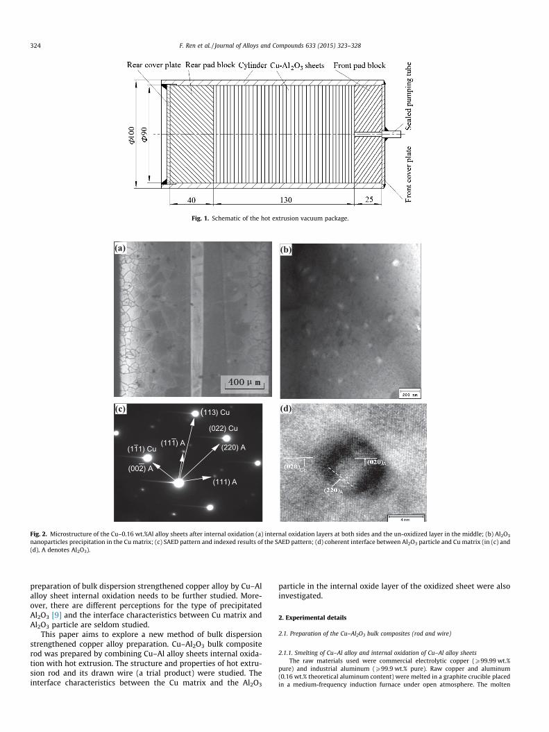
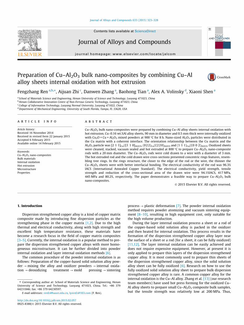
Fig. 1. Schematic of the hot extrusion vacuum package.
(a) (b)
(111) Cu
(022) Cu
(113) Cu
(111) A
(111) A
(220) A
(002) A
(c) (d)
Fig. 2. Microstructure of the Cu–0.16 wt.%Al alloy sheets after internal oxidation (a) internal oxidation layers at both sides and the un-oxidized layer in the middle; (b) Al2O3
nanoparticles precipitation in the Cu matrix; (c) SAED pattern and indexed results of the SAED pattern; (d) coherent interface between Al2O3 particle and Cu matrix (in (c) and(d), A denotes Al2O3).
324 F. Ren et al. / Journal of Alloys and Compounds 633 (2015) 323–328
preparation of bulk dispersion strengthened copper alloy by Cu–Alalloy sheet internal oxidation needs to be further studied. More-over, there are different perceptions for the type of precipitatedAl2O3 [9] and the interface characteristics between Cu matrix andAl2O3 particle are seldom studied.
This paper aims to explore a new method of bulk dispersionstrengthened copper alloy preparation. Cu–Al2O3 bulk compositerod was prepared by combining Cu–Al alloy sheets internal oxida-tion with hot extrusion. The structure and properties of hot extru-sion rod and its drawn wire (a trial product) were studied. Theinterface characteristics between the Cu matrix and the Al2O3
particle in the internal oxide layer of the oxidized sheet were alsoinvestigated.
2. Experimental details
2.1. Preparation of the Cu–Al2O3 bulk composites (rod and wire)
2.1.1. Smelting of Cu–Al alloy and internal oxidation of Cu–Al alloy sheetsThe raw materials used were commercial electrolytic copper (P99.99 wt.%
pure) and industrial aluminum (P99.9 wt.% pure). Raw copper and aluminum(0.16 wt.% theoretical aluminum content) were melted in a graphite crucible placedin a medium-frequency induction furnace under open atmosphere. The molten
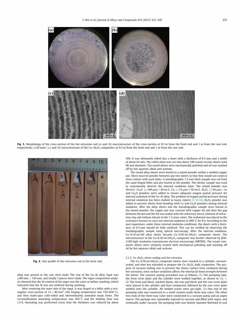
Fig. 3. Morphology of the cross-section of the hot extrusion rod (a) and (b) macrostructure of the cross-section at 0.5 m from the front end and 1 m from the rear end,respectively (£20 mm); (c) and (d) microstructure of the Cu–Al2O3 composites at 0.5 m from the front end and 1 m from the rear end.
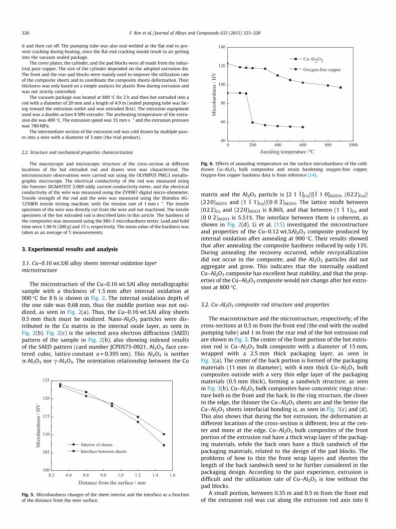
Fig. 4. Axis profile of the extrusion rod at the front end.
F. Ren et al. / Journal of Alloys and Compounds 633 (2015) 323–328 325
alloy was poured in the cast steel mold. The size of the Cu–Al alloy ingot was£80 mm � 150 mm, and totally 3 pieces were made. The ingot composition analy-sis showed that the Al content of the ingot was the same as before smelting, whichindicated that the Al was not oxidized during smelting.
After removing the outer skin of the ingot, it was forged to a billet with a rect-angular cross-section of 12 � 40 mm2 (the forging temperature was 750–850 �C),and then multi-pass cold-rolled and intermediately annealed many times. Therecrystallization annealing temperature was 450 �C and the holding time was1.5 h. Annealing was performed every time the thickness was reduced by about
30%. It was ultimately rolled into a sheet with a thickness of 0.5 mm and a widthof about 92 mm. The rolled sheet was cut into about 100 round circular sheets with90 mm diameter. The round sheets were mechanically polished and oil was washedoff by hot aqueous alkali and acetone.
The round alloy sheets were buried in a mixed powder within a welded copperpot. There must be powder between any two sheets so that they would not come inclose contact with each other. A metallographic 1.5 mm thick sample was cut fromthe same forged billet and also buried in the powder. The thicker sample was usedto conveniently observe the internal oxidation layer. The mixed powder was30 wt.% Cu2O (6100 lm) + 20 wt.% Cu (674 lm) + 50 wt.% Al2O3 (650 lm). Cuand Cu2O powders were added to ensure adequate oxygen partial pressure forinternal oxidation of the Cu–Al alloy. The problem of oxygen partial pressure duringinternal oxidation has been studied in many reports [7,10,14]. Al2O3 powder wasadded to prevent sheets from bonding with Cu and Cu2O powders during internaloxidation. After the alloy sheets and the metallographic sample were buried inthe mixed powder, the copper pot was covered with copper lid and then the gapbetween the pot and the lid was sealed with the refractory slurry (mixture of refrac-tory clay and sodium silicate in the 1:2 mass ratio). The sealed pot was placed in theresistance furnace to carry out internal oxidation at 900 �C for 8 h. According to thepast experience, under these internal oxidation conditions, the sheets with a thick-ness of 0.5 mm should be fully oxidized. This can be verified by observing themetallographic sample using optical microscopy. After the internal oxidation,Cu–0.16 wt.%Al alloy sheets became Cu–0.30 wt.%Al2O3 composite sheets. Themicrostructure of the Cu–0.30 wt.%Al2O3 composite was further observed by JEM-2100 high resolution transmission electron microscopy (HRTEM). The round com-posite sheets were similarly treated with mechanical polishing and washing offoil by hot aqueous alkali and acetone.
2.1.2. Cu–Al2O3 sheets sealing and hot extrusionThe Cu–0.30 wt.%Al2O3 composite sheets were stacked in a cylinder, vacuum-
sealed, and then hot extruded to prepare the Cu–Al2O3 bulk composites. The pur-pose of vacuum sealing was to prevent the sheets surface from oxidation duringhot extrusion, since surface oxidation affects the interfacial bond strength betweenthe sheets. The vacuum sealing procedure was as follows: (1) The pumping tube,the front cover plate and the cylinder were welded together, as shown in Fig. 1.(2) The front pad block, stacked sheets, the rear pad block and the rear cover platewere placed in the cylinder and then compacted, followed by the rear cover platewelded onto the cylinder. All welded seams were gas-tight. (3) One end of thepumping tube was connected to a small custom-made three-way valve. The othertwo ends of the three-way valve were connected to a vacuum pump and an argonsource. The package was repeatedly exposed to vacuum and filled with argon, andeventually under vacuum, the pumping tube was heated, hammer flattened to seal
0 200 400 600 800 100040
60
80
100
120
140
Mic
roha
rdne
ss /
HV
Anealing temperature /oC
Cu-Al2O3
Oxygen-free copper
Fig. 6. Effects of annealing temperature on the surface microhardness of the cold-drawn Cu–Al2O3 bulk composites and strain hardening oxygen-free copper.Oxygen-free copper hardness data is from reference [14].
326 F. Ren et al. / Journal of Alloys and Compounds 633 (2015) 323–328
it and then cut off. The pumping tube was also seal-welded at the flat end to pre-vent cracking during heating, since the flat end cracking would result in air gettinginto the vacuum sealed package.
The cover plates, the cylinder, and the pad blocks were all made from the indus-trial pure copper. The size of the cylinder depended on the adopted extrusion die.The front and the rear pad blocks were mainly used to improve the utilization rateof the composite sheets and to coordinate the composite sheets deformation. Theirthickness was only based on a simple analysis for plastic flow during extrusion andwas not strictly controlled.
The vacuum package was heated at 800 �C for 2 h and then hot extruded into arod with a diameter of 20 mm and a length of 4.9 m (sealed pumping tube was fac-ing toward the extrusion outlet and was extruded first). The extrusion equipmentused was a double-action 8 MN extruder. The preheating temperature of the extru-sion die was 400 �C. The extrusion speed was 35 mm s�1 and the extrusion pressurewas 780 MPa.
The intermediate section of the extrusion rod was cold drawn by multiple pass-es into a wire with a diameter of 3 mm (the trial product).
2.2. Structure and mechanical properties characterization
The macroscopic and microscopic structure of the cross-section at differentlocations of the hot extruded rod and drawn wire was characterized. Themicrostructure observations were carried out using the OLYMPUS PMG3 metallo-graphic microscope. The electrical conductivity of the rod was measured usingthe Foerster SIGMATEST 2.069 eddy current conductivity meter, and the electricalconductivity of the wire was measured using the ZY9987 digital micro-ohmmeter.Tensile strength of the rod and the wire was measured using the Shimdzu AG-1250KN tensile testing machine, with the tension rate of 1 mm s�1. The tensilespecimen of the wire was directly cut from the wire and not machined. The tensilespecimen of the hot extruded rod is described later in this article. The hardness ofthe composites was measured using the MH-3 microhardness tester. Load and holdtime were 1.96 N (200 g) and 15 s, respectively. The mean value of the hardness wastaken as an average of 5 measurements.
3. Experimental results and analysis
3.1. Cu–0.16 wt.%Al alloy sheets internal oxidation layermicrostructure
The microstructure of the Cu–0.16 wt.%Al alloy metallographicsample with a thickness of 1.5 mm after internal oxidation at900 �C for 8 h is shown in Fig. 2. The internal oxidation depth ofthe one side was 0.68 mm, thus the middle portion was not oxi-dized, as seen in Fig. 2(a). Thus, the Cu–0.16 wt.%Al alloy sheets0.5 mm thick must be oxidized. Nano-Al2O3 particles were dis-tributed in the Cu matrix in the internal oxide layer, as seen inFig. 2(b). Fig. 2(c) is the selected area electron diffraction (SAED)pattern of the sample in Fig. 2(b), also showing indexed resultsof the SAED pattern (card number JCPDS75-0921, Al2O3, face cen-tered cubic, lattice constant a = 0.395 nm). This Al2O3 is neithera-Al2O3 nor c-Al2O3. The orientation relationship between the Cu
0.2 0.4 0.6 0.8 1.0 1.2 1.4 1.6100
105
110
115
120
125
Mic
roha
rdne
ss /
HV
Distance from the surface / mm
Interior of sheets Interface between sheets
Fig. 5. Microhardness changes of the sheet interior and the interface as a functionof the distance from the wire surface.
matrix and the Al2O3 particle is [2 1 �1]Cu//[�1 1 0]Al2O3, (022)Cu//(220)Al2O3 and (1 �1 1)Cu//(0 0 �2)Al2O3. The lattice misfit between(022)Cu and (220)Al2O3 is 8.86%, and that between (1 �1 1)Cu and(0 0 �2)Al2O3 is 5.51%. The interface between them is coherent, asshown in Fig. 2(d). Li et al. [15] investigated the microstructureand properties of the Cu–0.12 wt.%Al2O3 composite produced byinternal oxidation after annealing at 900 �C. Their results showedthat after annealing the composite hardness reduced by only 13%.During annealing the recovery occurred, while recrystallizationdid not occur in the composite, and the Al2O3 particles did notaggregate and grow. This indicates that the internally oxidizedCu–Al2O3 composite has excellent heat stability, and that the prop-erties of the Cu–Al2O3 composite would not change after hot extru-sion at 800 �C.
3.2. Cu–Al2O3 composite rod structure and properties
The macrostructure and the microstructure, respectively, of thecross-sections at 0.5 m from the front end (the end with the sealedpumping tube) and 1 m from the rear end of the hot extrusion rodare shown in Fig. 3. The center of the front portion of the hot extru-sion rod is Cu–Al2O3 bulk composite with a diameter of 15 mm,wrapped with a 2.5 mm thick packaging layer, as seen inFig. 3(a). The center of the back portion is formed of the packagingmaterials (11 mm in diameter), with 4 mm thick Cu–Al2O3 bulkcomposites outside with a very thin edge layer of the packagingmaterials (0.5 mm thick), forming a sandwich structure, as seenin Fig. 3(b). Cu–Al2O3 bulk composites have concentric rings struc-ture both in the front and the back. In the ring structure, the closerto the edge, the thinner the Cu–Al2O3 sheets are and the better theCu–Al2O3 sheets interfacial bonding is, as seen in Fig. 3(c) and (d).This also shows that during the hot extrusion, the deformation atdifferent locations of the cross-section is different, less at the cen-ter and more at the edge. Cu–Al2O3 bulk composites of the frontportion of the extrusion rod have a thick wrap layer of the packag-ing materials, while the back ones have a thick sandwich of thepackaging materials, related to the design of the pad blocks. Theproblems of how to thin the front wrap layers and shorten thelength of the back sandwich need to be further considered in thepackaging design. According to the past experience, extrusion isdifficult and the utilization rate of Cu–Al2O3 is low without thepad blocks.
A small portion, between 0.35 m and 0.5 m from the front endof the extrusion rod was cut along the extrusion rod axis into 6
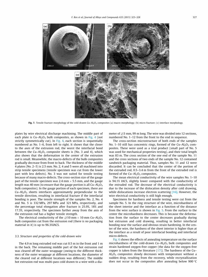
Fig. 7. Tensile fracture morphology of the cold-drawn Cu–Al2O3 composites (a) macro morphology; (b) micro fracture; (c) interface morphology.
F. Ren et al. / Journal of Alloys and Compounds 633 (2015) 323–328 327
plates by wire electrical discharge machining. The middle part ofeach plate is Cu–Al2O3 bulk composites, as shown in Fig. 4 (notstrictly symmetrically cut). In Fig. 4, each section is sequentiallynumbered as No. 1–6, from left to right. It shows that the closerto the axes of the extrusion rod, the worst the interfacial bondbetween the Cu–Al2O3 composite sheets is (No. 3 and 4), whichalso shows that the deformation in the center of the extrusionrod is small. Meanwhile, the macro-defects of the bulk compositesgradually decrease from front to back. The thickness of the middle4 plates (No. 2–5) is 2.5 mm. No. 2, 4 and 5 were all machined intostrip tensile specimens (tensile specimen was cut from the lowerpart with less defects). No. 3 was not suited for tensile testingbecause of many macro-defects. The cross-section size of the gaugepart of the tensile specimen was 2.4 mm � 5.5 mm, and the gaugelength was 40 mm (to ensure that the gauge portion is all Cu–Al2O3
bulk composites). In the gauge portion of each specimen, there areCu–Al2O3 sheets interfaces approximately perpendicular to thetensile direction, resulting in interfacial fracture if the interfacialbonding is poor. The tensile strength of the samples No. 2, No. 4and No. 5 is 332 MPa, 297 MPa and 321 MPa, respectively, andthe percentage total elongation after fracture is 25.9%, 18% and17.3%, respectively. The specimen farther away from the axis ofthe extrusion rod has a higher tensile strength.
The electrical conductivity of the £10 mm � 10 mm Cu–Al2O3
bulk composites cut from the extrusion rod (there is no packagingmaterial in it) is up to 96.3%IACS.
3.3. Structure and properties of the cold-drawn wire
The 4.9 m long extruded rod was cut 0.5 m in the front and 1 min the back. The remaining middle part of the hot extrusion rodwas cleared off the outer wrappage (owing to the different thick-ness of the outer wrappage at different locations, the diameter ofthe cleared rod at different locations was different). The middlehot extrusion rod was multi-pass cold drawn to a wire with a dia-
meter of £3 mm, 99 m long. The wire was divided into 12 sections,numbered No. 1–12 from the front to the end in sequence.
The cross-section microstructure of both ends of the samplesNo. 1–10 still has concentric rings, formed of the Cu–Al2O3 com-posites. These were used as a trial product (small part of No. 5was used for mechanical properties testing), and their total lengthwas 83 m. The cross section of the one end of the sample No. 11and the cross sections of two ends of the sample No. 12 containedsandwich packaging material. Thus, samples No. 11 and 12 werediscarded. It can be concluded that the center of the portion ofthe extruded rod, 0.5–3.4 m from the front of the extruded rod isformed of the Cu–Al2O3 composites.
The mean electrical conductivity of the wire samples No. 1–10is 94.1% IACS, slightly lower compared with the conductivity ofthe extruded rod. The decrease of the electrical conductivity isdue to the increase of the dislocation density after cold drawing,while dislocations increase electron scattering [16]. However, thewire electrical conductivity is still high enough.
Specimens for hardness and tensile testing were cut from thesample No. 5. In the ring structure of the wire, microhardness ofthe sheet interior and the interface as a function of the distancefrom the wire surface is shown in Fig. 5. From the surface to thecenter the microhardness decreases. This is because the deforma-tion from the surface to the center decreases gradually duringhot extrusion and cold drawing, resulting in better interfacialbonding near the surface and obvious strain hardening. In the cen-ter of the wire, the hardness of the sheet interior is higher than atthe interface as a result of poor interfacial bonding and interfacialmicro-defects.
Fig. 6 shows the effects of annealing temperature on the surfacemicrohardness of the cold-drawn Cu–Al2O3 bulk composites andstrain hardened oxygen-free copper (the data for the oxygen-freecopper is taken from the literature [17]). The hardness of the Cu–Al2O3 composites slowly decreases with temperature without asudden drop, resulting from the recovery, while recrystallizationdoes not occur in the composites after annealing below 900 �C
328 F. Ren et al. / Journal of Alloys and Compounds 633 (2015) 323–328
[17]. However, the hardness curve of the oxygen-free copper sud-denly drops in the 150–250 �C range, indicating recrystallization.
The measured yield and tensile strength of the cold-drawn Cu–Al2O3 bulk composites (£3 mm) is 417 MPa and 445 MPa, respec-tively. The tensile fracture morphology is shown in Fig. 7. Thenecking phenomenon is quite obvious in Fig. 7(a), and the reduc-tion of the cross-sectional area reaches 80%. The macro-fracturepresents the cup-cone morphology, which is typical for ductilefracture. The obvious circular axial interfacial crack in the centerof the fracture surface in Fig. 7(b) indicates poor interfacial bond-ing in the center. The interface of the sheets at the center can beseen, with some slight intermittent small holes are seen inFig. 7(c). There is less interface closer to the rim, which partiallydisappears.
The difference between the yield strength and the tensilestrength is very small, resulting from the early necking occurringdue to the internal defects, such as intermittent small holes.
To enhance the interfacial bonding and eliminate interfacialdefects in the center, increasing the extrusion temperature orextrusion ratio may be needed.
4. Conclusions
(1) The hot extrusion rod contained Cu–Al2O3 bulk compositesbetween 0.5 m and 3.9 m of the rod length. The center ofthe front portion of the hot extrusion rod was formed ofthe Cu–Al2O3 bulk composites, wrapped in a layer of packag-ing materials. The outside of the back portion was formed ofthe Cu–Al2O3 bulk composites with the packaging materialssandwich in the center. The electrical conductivity of thepure Cu–Al2O3 bulk composites in the extrusion rod was96.3%IACS.
(2) After cold drawing, pure Cu–Al2O3 bulk composite wire witha diameter of 3 mm and a length of 84 m was obtained. Theelectrical conductivity of the composite wire was 94.1%IACS.The tensile strength was 445 MPa and the reduction ofcross-sectional area reached 80%.
(3) After annealing below 900 �C, the hardness of the cold-drawn Cu–Al2O3 bulk composites decreased slowly withtemperature, which indicated that the material has excellentresistance to high temperature annealing.
Acknowledgements
This study was supported by the National Natural Science Foun-dation of China (51201061), by the Plan for Scientific Innovation
Talent of the Henan Province (144200510009), by the Henan Pro-vince Key Problem Project (092102210012), the Program forChangjiang Scholars and Innovative Research Team in University(IRT1234) and the program for Basic and Frontier TechnologiesResearch in Henan Province (112300410002).
References
[1] D.W. Lee, G.H. Ha, B.K. Kim, Synthesis of Cu–Al2O3 nano composite powder, Scr.Mater. 44 (2001) 2137–2140.
[2] C. Biselli, D.G. Morris, Mechanical alloying of high-strength copper alloyscontaining TiB2 and Al2O3 dispersoid particles, Scr. Metall. Mater. 30 (1994)1327–1332.
[3] Meslet Al-Hajri, Aldo Melendez, R. Woods, T.S. Srivatsan, Influence of heattreatment on tensile response of an oxide dispersion strengthened copper, J.Alloys Comp. 290 (1999) 290–297.
[4] B.H. Tian, P. Liu, K.X. Song, Y. Li, Y. Liu, F.Z. Ren, J.H. Su, Microstructure andproperties at elevated temperature of a nano-Al2O3 particles dispersion-strengthened copper base composite, Mater. Sci. Eng., A 435–436 (2006) 705–710.
[5] M.S. Motta, P.K. Jena, E.A. Brocchi, I.G. Solórzano, Characterization of Cu–Al2O3
nano-scale composites synthesized by in situ reduction, Mater. Sci. Eng., C 15(2001) 175–177.
[6] Y.J. Li, F.Z. Ren, X.W. Wang, Y. Li, S.Z. Wei, Comparative study of internaloxidation microstructure of Cu–Al alloy with different Al content, Trans. Mater.Heat Treat. 35 (2014) 29–32 (in Chinese).
[7] R.H. Liu, K.X. Song, S.G. Jia, X.F. Xu, J.X. Gao, X.H. Guo, Morphology andfrictional characteristics under electrical currents of Al2O3/Cu compositesprepared by internal oxidation, Chin. J. Aeronaut. 21 (2008) 281–288.
[8] J. Grona, Heat-resistant dispersion-strengthened copper alloys, J. Mater. Eng.Perform. 1 (1992) 113–121.
[9] G.B. Li, J.B. Sun, Q.M. Guo, R. Wang, Fabrication of the nanometer Al2O3/Cucomposite by internal oxidation, J. Mater. Process. Technol. 170 (2005) 336–340.
[10] K.X. Song, J.D. Xing, Q.M. Dong, P. Liu, B.H. Tian, X.J. Cao, Internal oxidation ofdilute Cu–Al alloy powers with oxidant of Cu2O, Mater. Sci. Eng., A 380 (2004)117–122.
[11] S. Wood, D. Adamonis, A. Guha, W.A. Soffa, G.H. Meier, Internal oxidation ofdilute Cu–Ti alloys, Metall. Trans. A 6 (1975) 1793–1800.
[12] F.F. Su, D.W. Zhang, D.M. Zhao, F.Z. Ren, B.H. Tian, S.G. Jia, Microstructure andproperties of Cu–Al alloy sheet after internal oxidation, Trans. Mater. HeatTreat. 30 (2009) 101–104 (in Chinese).
[13] X.N. Zhang, D.W. Zhang, D.M. Zhao, P. Liu, F.Z. Ren, B.H. Tian, Study onmicrostructure of hot-extruded dispersion-strengthened Al2O3/Cu composite,Hot Work. Technol. 36 (2007) 7–9 (in Chinese).
[14] F.H. Scott, G.C. Wood, Internal oxidation, Mater. Sci. Technol. 4 (1988) 1072–1078.
[15] H.X. Li, B.H. Tian, Y.M. Lin, S.K. Li, P. Liu, Recrystallization behavior of Al2O3/Cucomposite produced by internal oxidation, Rare Met. Mater. Eng. 34 (2005)1039–1042 (in Chinese).
[16] F.Z. Ren, J. Wang, Z.H. Ma, J.H. Su, S.G. Jia, Properties of Cu and Fe under largedeformation and strength calculation of Cu–115% Fe in situ composites, Trans.Mater. Heat Treat. 30 (2009) 17–21 (in Chinese).
[17] J.Y. Cheng, X.W. Ao, M.P. Wang, M.X. Guo, Effect of Al2O3 dispersed onmicrostructure of Cu–Al2O3 alloy annealed at elevated temperatures, Chin. J.Nonferr. Met. 19 (2009) 1928–1933 (in Chinese).