Joshua Felty's Undergraduate Portfolio
34
description
A portfolio covering the undergraduate work of Joshua Felty at Texas Tech University from Spring 2011 to Fall 2013.
Transcript of Joshua Felty's Undergraduate Portfolio

table of contents
studio construction
studio i
studio ii
studio iii
studio iv
studio v
studio vi
1
5
9
13
17
21
25
27
construction i
construction iii

STAGE ONE
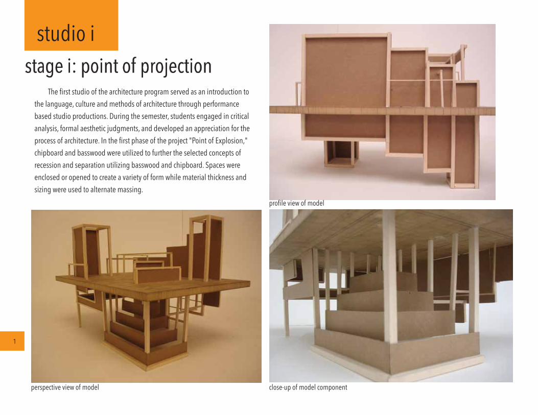
studio istage i: point of projection
1
The first studio of the architecture program served as an introduction to the language, culture and methods of architecture through performance based studio productions. During the semester, students engaged in critical analysis, formal aesthetic judgments, and developed an appreciation for the process of architecture. In the first phase of the project "Point of Explosion," chipboard and basswood were utilized to further the selected concepts of recession and separation utilizing basswood and chipboard. Spaces were enclosed or opened to create a variety of form while material thickness and sizing were used to alternate massing.
perspective view of model close-up of model component
profile view of model
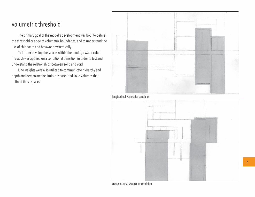
volumetric threshold
2
The primary goal of the model's development was both to define the threshold or edge of volumetric boundaries, and to understand the use of chipboard and basswood systemically.
To further develop the spaces within the model, a water color ink-wash was applied on a conditional transition in order to test and understand the relationships between solid and void.
Line weights were also utilized to communicate hierarchy and depth and demarcate the limits of spaces and solid volumes that defined those spaces.
cross-sectional watercolor condition
longitudinal watercolor condition
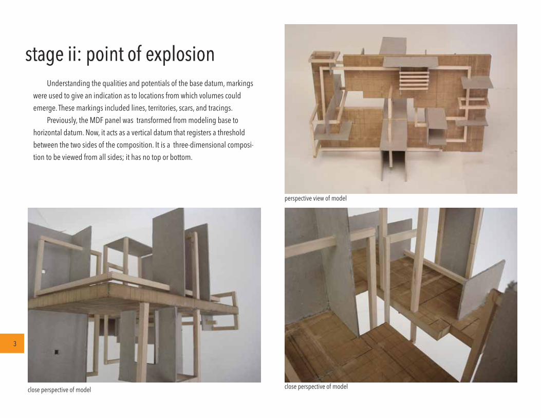
stage ii: point of explosionUnderstanding the qualities and potentials of the base datum, markings
were used to give an indication as to locations from which volumes could emerge. These markings included lines, territories, scars, and tracings.
Previously, the MDF panel was transformed from modeling base to horizontal datum. Now, it acts as a vertical datum that registers a threshold between the two sides of the composition. It is a three-dimensional composi-tion to be viewed from all sides; it has no top or bottom.
close perspective of model
perspective view of model
close perspective of model
3
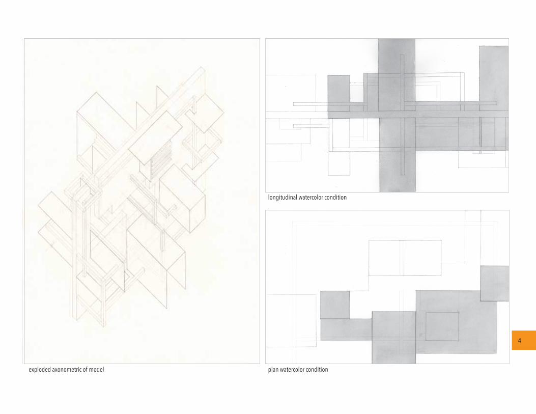
exploded axonometric of model plan watercolor condition
longitudinal watercolor condition
4

12
4 5
6
7
3
8
2
1
2
3
4
5
6
7
8
9
lobby
interior exhibition space
exterior exhibition space
men’s restroom
women’s restroom
office
main office
storage
parking space
N
9
site and roof plan [with shadows]
studio iidesign synthesis i: art gallery
5
The studio began with a design analysis of a currently-existing structure in order to obtain a clear understanding of the three components of architecture, space typology, and ideas of constants and variables. Then, the studio begin testing these fundamental notions of architecture through iterations on a designated urban site. This first design consisted of an exhibition facility within an urban setting and a sloped site. The building program demanded two interior galleries and an outdoor exhibition space. During the design, a proper floor plan was composed by keeping sunlight, pedestrian and vehicular traffic in mind so as to capitalize on pre-existing site conditions.

cross-section
back elevationfront elevation
longitudinal section
perspective of model [isolated] back perspective of model [in site] front perspective of model [in site]
sections
6

roof level
second floor
river floor
ground / first floor
perspective of model in site model
perspective of model [isolated]
N
design synthesis ii: water museum
7
As in the previous design synthesis, the second project proposal had to respond to the existing site conditions and the three components of architecture. However, in this scheme for a water museum, there is greater emphasis on interior circulation, however, due to the necessity of vertical circulation in the program. This scheme also included stairs and ramps that required ADA compli-ance and removal of parking facilities. Critical analysis was based on the applica-tion and composition of four space typologies: place, path, transition and servant.

east elevationsouth elevation
cross section
west elevation
side view of model
perspective of model [in site]
longitudinal section
8

perspective of model [south]
ground-level perspective of model
perspective of model [east]
studio iiisite+program: community center
9
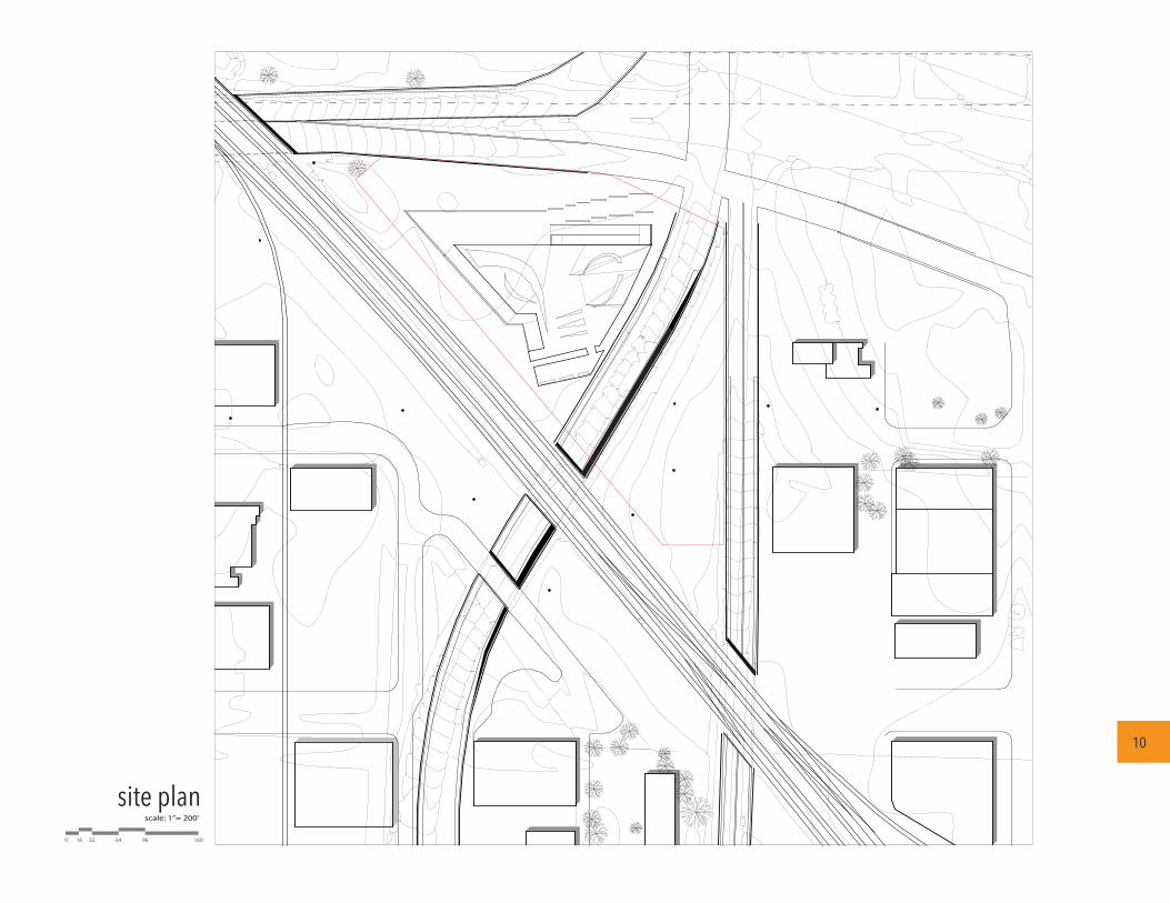
In the third studio, the students were introduced to 'architectural program-ming.' This is the determination of design needs, and the appropriate responses of the program to those needs. These include examining context and other determinates in the site. The project for this studio incorporated these consider-ations into the design of a community center, which features heated and condi-tioned pools, lockers, office and ramps for entering and exiting the facility. The geometry, plan configuration, and orientation of the structure took into account previously-existing infrastructure, pedestrian traffic, and landscape condition during the design phase leading up to the final iteration.
site plan
0 643216 96 160
scale: 1”= 200’
10
site plan

first sub-floor
ground floor second sub-floor
0 28147 42 70
0 28147 42 70 0 28147 42 70
1
2
12
conditioned poolstairs
123456789
Conditioned PoolLobbyMen’s LockersWomen’s LockersMen’s ShowersWomen’s ShowersHeated PoolsOfficesstairs
12
Entrance RampExit Ramp
second sub-floor
1
2
3
9
4
5
6
88
8
7
7
7
1
2
first sub-floor
ground floor
N
N N
A
A
A
B
B
B
C
C
C
floor plans
11

cross-section aScale: 1” = 56’
cross-section bScale: 1” = 56’
longitudinal section [ c ]Scale: 1” = 56’
0 28147 42 70
0 28147 42 70
0 28147 42 70
12
sections

N
open to above
open to above
open to below
open to below
8
8
8
1
2
313
12
10
11
9
9
9
7
5
4
4
6
6
13
12studio ivstructure + system + code: recreation center
13
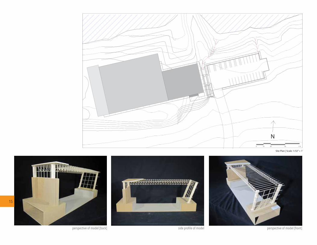
The fourth studio introduced students to the critical considerations of life safety, accessibility, and building codes into their designs. Building codes impact the everyday work of architects and thus the project has to take into account the impact of these legal measures. The project was the design of a recreation center, featuring a pool, exercise rooms, showers, bathrooms and restrooms. The student presented and reiterated project elements based on an understanding of structure, materials, and assemblies. This led to the final design solution, which utilizes natural lighting and incremental spacing to provide provide an enhanced functionality.
floor plans
first floor | scale: 1” = 34’
second floor | scale: 1” = 34’
12345678
lobbyconcession areapool areamen’s restroomwomen’s restroommen’s locker roomwomen’s locker roomexercise room
910111213
officereception / equipment roommechanical roomstairselevator

This is where your text will go.
Write whatever �ts this project
longitudinal section | scale: 1/8” = 4’
cross Section | scale: 1/8” = 4’
14
sections
0 1684 24 40
0 1684 24 40
N
Site Plan | Scale: 1/32” = 1’
15
perspective of model [back] perspective of model [front]side profile of model
190 38 76 114
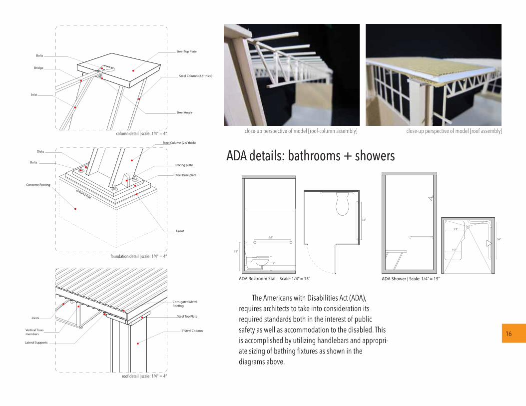
Concrete Footing
Bolts
Disks
Bracing plate
Grout
Steel base plate
Steel Column (2.5’ thick)
Steel Column (2.5’ thick)
Steel Top Plate
Joist
Bridge
Bolts
Steel Angle
Corrugated Metal Roo�ng
2’ Steel Column
Steel Top Plate
Lateral Supports
Vertical Trussmembers
Joists
roof detail | scale: 1/4” = 4”
foundation detail | scale: 1/4” = 4”
column detail | scale: 1/4” = 4”
ground-line
17”
33”
36”
36”
15”
23”
34”
ADA Restroom Stall | Scale: 1/4” = 15’ ADA Shower | Scale: 1/4” = 15”
ADA details: bathrooms + showers
16
The Americans with Disabilities Act (ADA), requires architects to take into consideration its required standards both in the interest of public safety as well as accommodation to the disabled. This is accomplished by utilizing handlebars and appropri-ate sizing of bathing fixtures as shown in the diagrams above.
close-up perspective of model [roof-column assembly] close-up perspective of model [roof assembly]
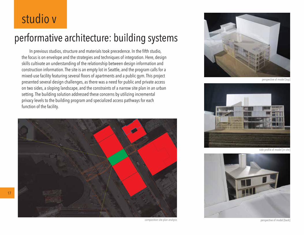
studio vperformative architecture: building systems
17
In previous studios, structure and materials took precedence. In the fifth studio, the focus is on envelope and the strategies and techniques of integration. Here, design skills cultivate an understanding of the relationship between design information and construction information. The site is an empty lot in Seattle, and the program calls for a mixed-use facility featuring several floors of apartments and a public gym. This project presented several design challenges, as there was a need for public and private access on two sides, a sloping landscape, and the constraints of a narrow site plan in an urban setting. The building solution addressed these concerns by utilizing incremental privacy levels to the building program and specialized access pathways for each function of the facility.
perspective of model [back]composition site plan analysis
side profile of model [in site]
perspective of model [top]

18
landscape sections

0 5 10 20 30ft
0 5 10 20 30ft
0 5 10 20 30ft
19
sections
longitudinal section
cross-section section bcross-section section a
0 10 20 40 60ft
0 4 61 2ft
20
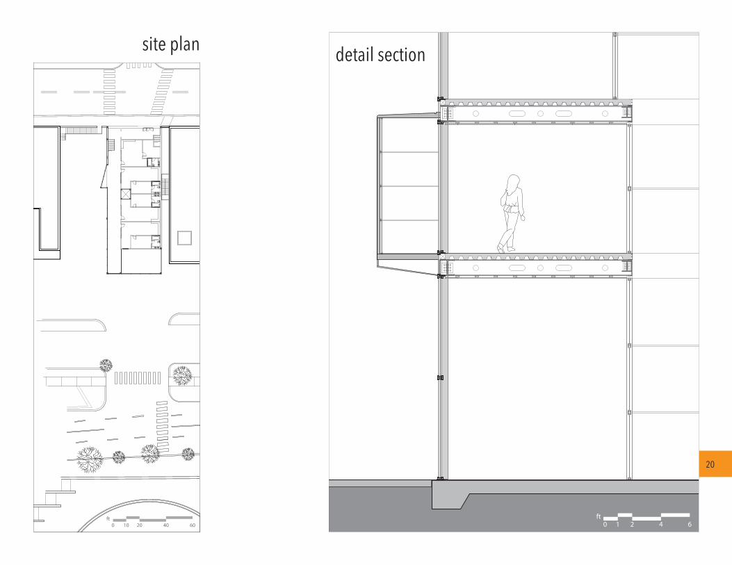
detail sectionsite plan

section b
section a
0 5 10 15 20
0 5 10 15 20
perspective of model [ se corner]perspective of model [ nw corner]
sections
urbanism: multi-use parking garage
studio vi
21
In light of the lack of sustainability in the suburban built environment, density becomes ever more paramount. In the sixth and final studio, the focus was to prepare students for the challenge of providing adequate public space, and designing buildings to define that space. This was done through immersion in a urban environment and studying the connection between buildings and a city's public space. For this project, the program called for an underground parking garage, along with a multi-story restaurant, and a chapel. In addition, the students were encouraged to add more green space to the urban environment to encourage more sustainable architectural practices. By design-ing a solution with multiple functions within the same site, the ultimate intent of this studio was successful in providing an introduction to designing for the urban landscape.
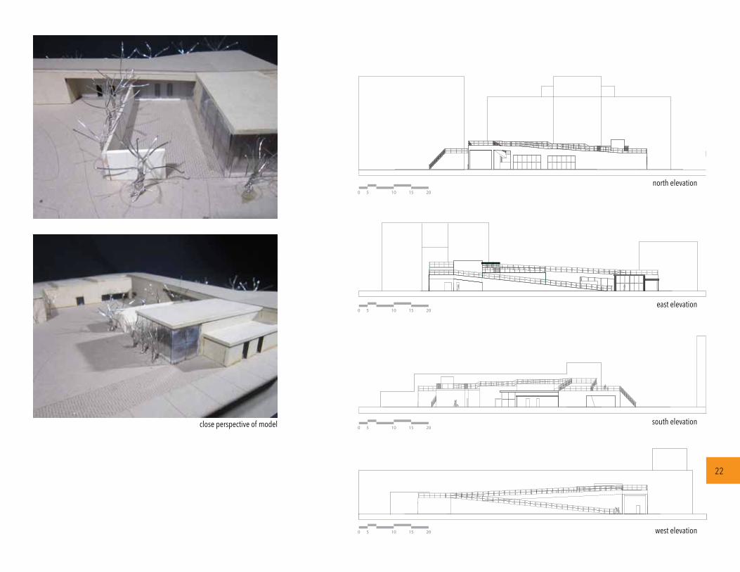
east elevation
south elevation
west elevation
north elevation
0 5 10 15 20
0 5 10 15 20
0 5 10 15 20
0 5 10 15 20
close perspective of model
22

highlineolympic sculpture park
0
N
5 10 15 20
0
N
5 10 15 20
0
N
5 10 15 20first & second sub-floor
first floorsecond floor
b
a
b
a
precedent studies:
floor plans
23
To encourage more green space in the urban environment, the project
incorporated green space atop the ramps that circulate on the site. Research into
the matter led to the selection of two precedent studies: the Olympic Sculpture Park
in Seattle, and the Highline in New York City. Both were appropriate precedent
studies due to their successful incorporation of green space, infrastructure, and
urbanism.
123456789
1011
121314151617181920
21222324
waiting areakitchendining spacebarmen’s restroomwomen’s restroomcold storagewarm storageemployee lockersstairsloading dock
elevatorcourtyardchapelserving kitchenmen’s changing roomwomen’s changing roommen’s restroom [public]women’s restroom [public]decking [outdoor dining]
parking entrancecar rampparking spacemechanical room [hvac]
1
10
4
3
33
2
5
5 6
6
16
19
17
20
22
18
987
3
12
1415
13
1011
10
202020
10
10
12 10
22
23
24
23

Scale: 1/4” = 1’-0”
01. sectionScale: 1/4” = 1’-0”
02. elevation
D.05
3.0D.0B.0
D.04
D.03
T.O. Roof
B.O. Roof
T.O. Plate @ Catwalk19’-0 3/8”
1’-10”
22’-6 3/8”
B.O. Screen Wall
Slab @ Sidewalk
04
01
Footing with keyed Joint
0’-0”T.O. Slab @ GroundFloor
05
06
03
02
01
02
03
04
05
06
Drainage Mat
Key Joint
3/8 “ Rebar
Weatherproofing
Weep Hole
Metal Flashing
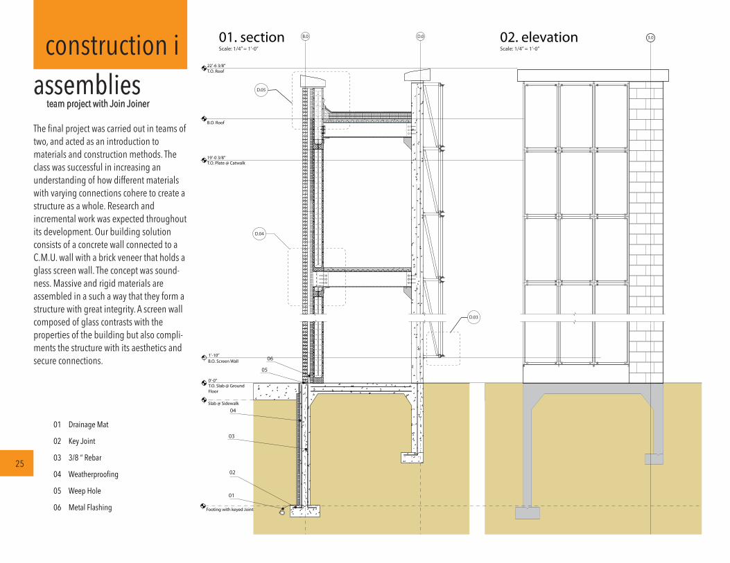
construction iassemblies team project with Join Joiner
25
The final project was carried out in teams of two, and acted as an introduction to materials and construction methods. The class was successful in increasing an understanding of how different materials with varying connections cohere to create a structure as a whole. Research and incremental work was expected throughout its development. Our building solution consists of a concrete wall connected to a C.M.U. wall with a brick veneer that holds a glass screen wall. The concept was sound-ness. Massive and rigid materials are assembled in a such a way that they form a structure with great integrity. A screen wall composed of glass contrasts with the properties of the building but also compli-ments the structure with its aesthetics and secure connections.
Scale: 9” = 1’-0”03. detail
Scale: 3” = 1’-0”05. detail
Scale: 3” = 1’-0”04. detail
07
08
09
10
11
12
13
14
15
16
17
18
2” Rigid Insulation Shelf Angle
1 3/4” Steel tube
Leg Angle
8” Concrete Masonry Unit
2“ Brick Unit
12” Steel Beam
Wall Tie
Steel Angle
Concrete Corbel
Steel Decking
Site Welded Plate
19
20
21
22
23
24
25
26
27
28
29
2” Air Space
2” Rigid Isulation
Single Ply Roof Membrane
Roof Insulation
Pressure Treated Wood Nailer
Built Up Modified Bitumen
Cant Strip
Metal Cleat
Stone Coping
Ballast
2” Glass
27
24
25
23
14
22
26
18
29
1509
08
08
1112
15
17
13
20
19
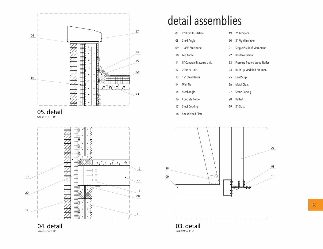
detail assemblies
26
02
10
s e c t i o n A [ s c a l e 1 / 8 ” : 7 ’ - 6 ” ]
b u i l d i n g e l e v a t i o n [ s c a l e 1 / 4 ” : 1 3 ’ - 0 ” ]
+12’-0”
036
0 13 26 39 65
0 15 30 45 75
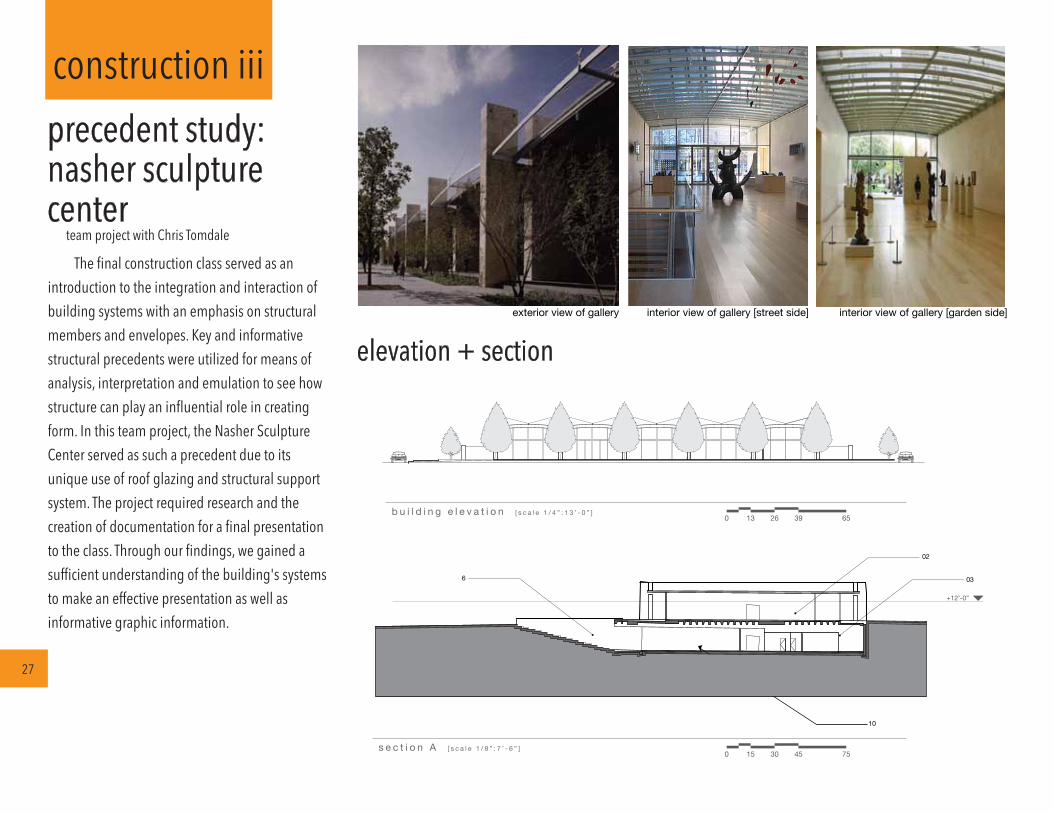
interior view of gallery [garden side]interior view of gallery [street side]exterior view of gallery
The final construction class served as an introduction to the integration and interaction of building systems with an emphasis on structural members and envelopes. Key and informative structural precedents were utilized for means of analysis, interpretation and emulation to see how structure can play an influential role in creating form. In this team project, the Nasher Sculpture Center served as such a precedent due to its unique use of roof glazing and structural support system. The project required research and the creation of documentation for a final presentation to the class. Through our findings, we gained a sufficient understanding of the building's systems to make an effective presentation as well as informative graphic information.
elevation + section
construction iii
27
precedent study:nasher sculpturecenter team project with Chris Tomdale
213’
N
0s i t e p l a n [ s c a l e 1 / 8 ” : 1 1 ’ - 0 ” ]
11 22 44 66 110
A A
B
B
6
1
22
10
1111
12
13
14
15
15
8
16
17
17
17
18
171717
17
19
1 1
2
34
5
2
6
7 7
8
2
9
N
0 3417 68 136fl o o r p l a n [ s c a l e 1 / 8 ” : 1 7 ’ - 0 ” ]
01.
02.
03.
04.
05.
06.
07.
08.
09.
10.
11.
12.
13.
14.
15.
16.
17.
18.
19.
gallery
lobby
gift shop
coffee shop
restaurant
exterior multi-
purpose room
office
kitchen
security
multi-purpose room
bathroom
art storage
storage
restoration room
institution
staging room
mechanical
employee break
loading dock
basement
ground floor
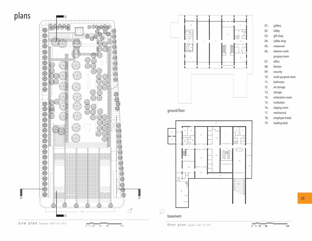
plans
28
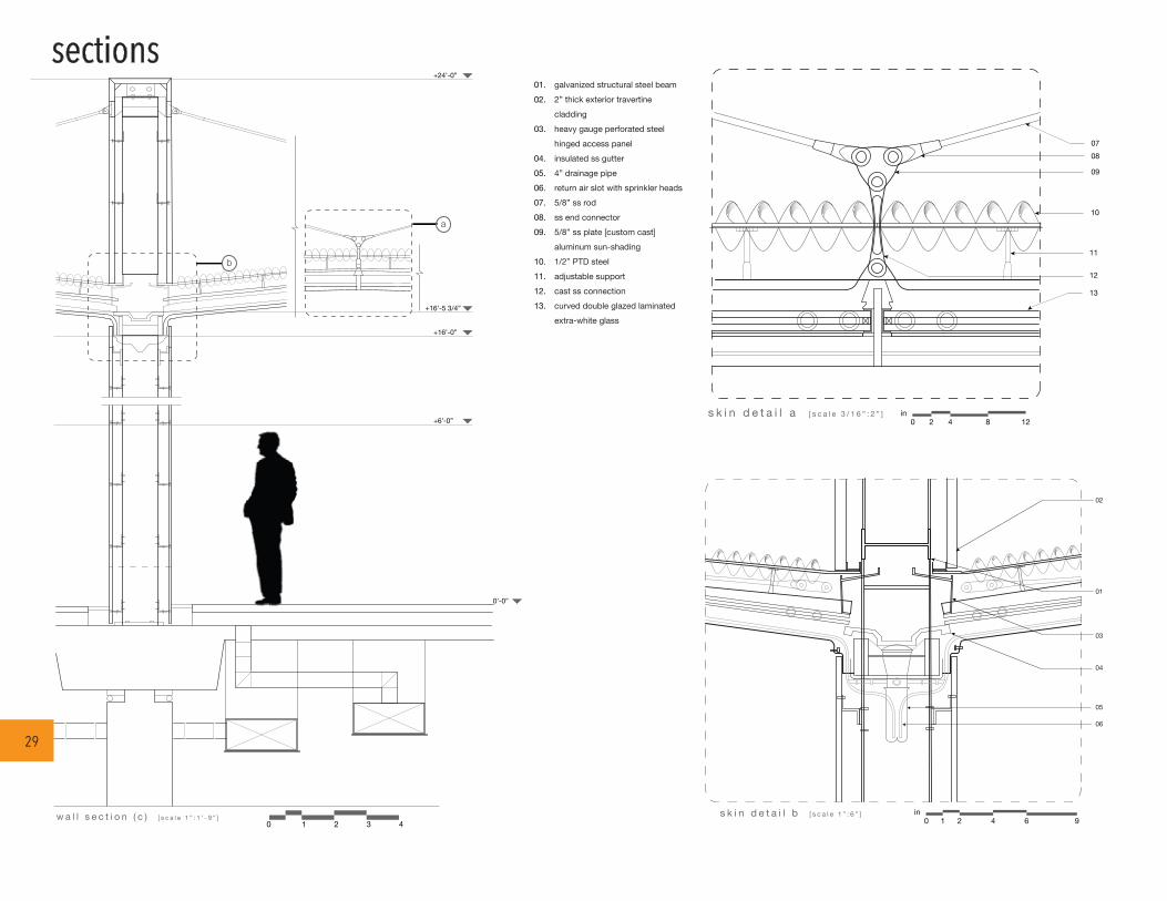
0w a l l s e c t i o n ( c ) [ s c a l e 1 ” : 1 ’ - 9 ” ]
1
01
03
02
s k i n d e t a i l b [ s c a l e 1 ” : 6 ” ]
b
08
09
07
s k i n d e t a i l a [ s c a l e 3 / 1 6 ” : 2 ” ]
+24’-0”
+16’-5 3/4”
+16’-0”
+6’-0”
0’-0”
2 43
a10
11
12
01.02.
03.
04.05.06.07.08.09.
10.11.12.13.
04
05
06
13
galvanized structural steel beam2” thick exterior travertine claddingheavy gauge perforated steel hinged access panelinsulated ss gutter4” drainage pipereturn air slot with sprinkler heads5/8” ss rodss end connector5/8” ss plate [custom cast]aluminum sun-shading1/2” PTD steeladjustable supportcast ss connectioncurved double glazed laminated extra-white glass
0in
1 2 4 6 9
0 2 4 8 12in
gallery
lobby
gift shop
coffee shop
restaurant
exterior multi-
purpose room
office
kitchen
security
multi-purpose room
bathroom
art storage
storage
restoration room
institution
staging room
mechanical
employee break
loading dock
sections
29

perspective of roof cable and shading systems
renderings
30
perspective of building section detail model perspective [tower]
detail model perspective [roofing]