Joints with Dowel Type Fasteners in CLT Structures
15
Joints with Dowel Type Fasteners in CLT Structures Thomas Uibel Professor for Timber Structures and Basics of Structural Engineering Timber Engineering Group, Faculty of Civil Engineering, FH Aachen Aachen, Germany Hans Joachim Blaß Professor for Timber Engineering and Building Construction Versuchsanstalt für Stahl, Holz und Steine, Karlsruhe Institute of Technology (KIT) Karlsruhe, Germany Summary The load carrying capacity of joints with dowel type fasteners in cross laminated timber (CLT) was the focus of a research project [1], [2], [3] conducted by the authors at Karlsruhe Institute of Technology (KIT). To examine the influence of load duration and climate variation on the load carrying capacity, these studies were complemented by long-term tests with screws in CLT, started in 2007 and finished at the end of 2012. In this paper the results of embedment tests, withdrawal tests and connection tests are discussed and proposals for the calculation of characteristic values are given. On this basis calculation models for the load carrying capacity of joints with dowel type fasteners in the plane side of cross laminated timber and for edge joints were developed. Furthermore long-term tests with screws are presented. 1. Introduction Cross laminated timber (CLT) has been used more and more frequently in timber engineering in recent years. Their use in constructions requires their connection with each other and with other components of the construction. To that purpose dowel type fasteners can be used. It is possible to position the fasteners perpendicular to the plane of the CLT panels or in the edges (Fig. 1). To calculate the load carrying capacity of dowel type fasteners according to Johansen’s yield theory [4], [5], [6], [7] the yield moment of the fasteners and the embedding strength are needed. The withdrawal strength is necessary to calculate the load carrying capacity of axially loaded screws. In addition, the withdrawal strength is important for estimating the rope effect of laterally loaded connections. In the edges of CLT the fasteners can be positioned parallel to the grain direction. The embedment strength and the withdrawal strength are also influenced by gaps and grooves. The aim of the research project at the KIT [1], [2], [3] was to develop proposals for calculating the load carrying capacity of joints with dowel type fasteners in solid wood panels. Furthermore the long-term behaviour of edge joints with self-tapping screws was examined.
Transcript of Joints with Dowel Type Fasteners in CLT Structures

Joints with Dowel Type Fasteners in CLT Structures
Thomas Uibel Professor for Timber Structures and Basics of Structural Engineering Timber Engineering Group, Faculty of Civil Engineering, FH Aachen
Aachen, Germany
Hans Joachim Blaß Professor for Timber Engineering and Building Construction
Versuchsanstalt für Stahl, Holz und Steine, Karlsruhe Institute of Technology (KIT) Karlsruhe, Germany
Summary
The load carrying capacity of joints with dowel type fasteners in cross laminated timber (CLT) was the focus of a research project [1], [2], [3] conducted by the authors at Karlsruhe Institute of Technology (KIT). To examine the influence of load duration and climate variation on the load carrying capacity, these studies were complemented by long-term tests with screws in CLT, started in 2007 and finished at the end of 2012.
In this paper the results of embedment tests, withdrawal tests and connection tests are discussed and proposals for the calculation of characteristic values are given. On this basis calculation models for the load carrying capacity of joints with dowel type fasteners in the plane side of cross laminated timber and for edge joints were developed. Furthermore long-term tests with screws are presented.
1. Introduction
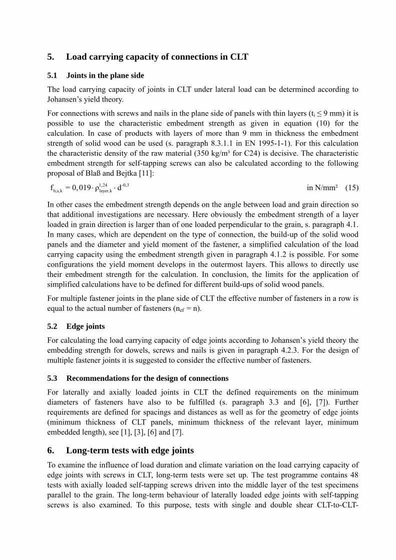
Cross laminated timber (CLT) has been used more and more frequently in timber engineering in recent years. Their use in constructions requires their connection with each other and with other components of the construction. To that purpose dowel type fasteners can be used. It is possible to position the fasteners perpendicular to the plane of the CLT panels or in the edges (Fig. 1). To calculate the load carrying capacity of dowel type fasteners according to Johansen’s yield theory [4], [5], [6], [7] the yield moment of the fasteners and the embedding strength are needed. The withdrawal strength is necessary to calculate the load carrying capacity of axially loaded screws. In addition, the withdrawal strength is important for estimating the rope effect of laterally loaded connections. In the edges of CLT the fasteners can be positioned parallel to the grain direction. The embedment strength and the withdrawal strength are also influenced by gaps and grooves.
The aim of the research project at the KIT [1], [2], [3] was to develop proposals for calculating the load carrying capacity of joints with dowel type fasteners in solid wood panels. Furthermore the long-term behaviour of edge joints with self-tapping screws was examined.

48
146
self-tapping screw8.0 x 280
134
Fig. 1 Opened connection with dowels in cross laminated timber (left), example for an edge joint with self-tapping screws in cross laminated timber (right)
2. Test material
Cross laminated timber panels consist of boards crosswise laminated with a minimum of three layers. Some panels are produced with gaps between the edges of the boards. For these studies CLT made of European spruce (Picea abies) from 4 manufactures with altogether 13 different build-ups were used. For the used products the maximum width of gaps is limited to 6 mm. In addition, grooves with a width of about 2,5 mm are sawn into the boards of some products. Fig. 2 shows cross-sections of different CLT products. Table 1 gives some statistic information about the gaps.
Fig. 2 Cross-sections of panels without and with gaps between boards and grooves
plane side
edge
plane side

Table 1 Width of gaps between boards of one layer for some different products M
anuf
actu
rer/
prod
uct
Build-up
Width (in mm) of gaps in
Outer layers Interlayers Centre layer
mean max.95%
fractile mean max.
95% fractile
mean max. 95%
fractile
1 17-17-17-17-17 0,6 2,1 1,6 1,6 7,3 3,4 1,0 3,0 2,3
2 19-22-19 0,4 2,0 1,3 - - - 0,5 2,2 1,8
2 34-13-34-13-34 0,2 1,0 1,0 1,4 6,8 3,3 2,0 6,7 4,5
4 9,5-6,8-9,5-6,8-9,5 0 0 0 0,6 5,4 3,5 0 0 0
The characteristic density (at normal climate, 20°C/65% RH) of cross laminated timber was determined by analysing altogether 2299 test specimens out of a range of products from different manufacturers (Table 2). This revealed a minimum 5th percentile density of 400 kg/m³ for product 2. Taking this result into account a characteristic density of 400 kg/m³ is proposed for cross laminated timber panels made of European spruce (Picea abies).
Table 3 shows the statistical summary of the density of the specimens for withdrawal tests with self-tapping screws in CLT. Table 4 gives this information for the test specimens of embedment tests with dowel type fasteners positioned in the edges of CLT. This table gives also a comparison between the density of the whole cross section and the density of the relevant layer in which the fastener is positioned.
Table 2 Density of cross laminated timber panels at normal climate, 20°C/65% RH
Manufacturer/ product
n ρmean
kg/m³
ρmin
kg/m³
ρmax
kg/m³
Coefficient of variation
ρ0,05
kg/m³
1 515 470 415 630 5,11 % 430
2 906 437 372 578 6,02 % 400
3 208 458 406 507 5,18 % 423
4 670 459 397 558 5,75 % 419
Table 3 Density of the specimens for withdrawal tests with screws in cross laminated timber panels at normal climate, 20°C/65% RH
Manufacturer/ product
Density of the specimen for withdrawal tests
Plane side (hole cross section) Edge (relevant layers)
n
ρmean
kg/m³ Coefficient of variation
ρ0,05
kg/m³ n
ρmean
kg/m³Coefficient of variation
ρ0,05
kg/m³
1 24 454 4,48 % 423 57 448 8,21 % 374
2 73 426 5,44 % 384 159 404 11,9 % 335
3, 4 22 445 3,34 % 420 52 435 8,29 % 382

Table 4 Density of the specimens for embedment tests with dowel type fasteners in the edges of cross laminated timber panels at normal climate, 20°C/65% RH
Manufacturer/ product
n
Density of the whole cross section
Density of the relevant layers
ρmean
kg/m³ Coefficient of variation
ρ0,05
kg/m³ ρmean
kg/m³ Coefficient of variation
ρ0,05
kg/m³
1 184 474 5,76 % 434 481 9,54 % 412
2 292 439 7,65 % 391 417 12,2 % 345
3, 4 233 452 5,55 % 413 461 9,89 % 401
3. Axially loaded self-tapping screws
3.1 Set-up for withdrawal tests
To determine the withdrawal strength of self-tapping screws in CLT 119 tests with screws placed perpendicular to the plane of CLT and 268 tests with screws in the edges of CLT were carried out according to EN 1382 [8]. In the tests the positions of screws were varied, as shown in Fig. 3 and 4. In the plane side they were positioned in areas without gaps (position 1.1) and placed in gaps (position 1.2 to 1.4). Screws driven perpendicular (position C) and parallel (positions A, B) to the grain were considered in the edge withdrawal tests. Furthermore, tests with screws placed in gaps (positions B.1, B.2) were taken into consideration to derive the withdrawal capacity.
F
10·d
t
5·d 5·d
F
10·d 5·d 5·d
t
t
F
10·d 5·d 5·d
F
10·d 5·d 5·d
t
Anordnung: 1.1 1.2 1.3 1.4
Fig. 3 Set-up for withdrawal tests with screws positioned perp. to the plane of CLT
Fig. 4 Set-up for edge withdrawal tests with screws in CLT
t
F
F
t
F
t
F
t
Anordnung: A B 1 B 2 CPosition A B.1 B.2 C
Position 1.1 1.2 1.3 1.4

3.2 Results of withdrawal tests
The best correlation between test results and predicted values can be achieved if the withdrawal capacity of self-tapping screws in CLT is calculated according to the following expression:
0,8 0,9 0,75ef
ax,s,pred 2 2
0, 44 d ρR =
1,25 cos + sin
r = 0,91
in N (1)
with
d nominal or outer diameter of the screw in mm
ef effective pointside penetration length in mm
joints in the plane side of CLT: = 90°, edge joints: = 0°
for joints in the plane side of CLT: density of CLT (whole cross section) in kg/m³
for edge joints in CLT: density of the relevant layer(s) in kg/m³
Fig. 5 (left) shows the test results vs. the predicted values. The correlation coefficient r is equal to 0,91. To simplify equation (1) the characteristic density of CLT is inserted and the denominator is increased up to 1,5. A further adaptation results in equation (2) for the characteristic withdrawal capacity. The right diagram in Fig. 5 shows the verification of the characteristic values.
0,8 0,9 0,75 0,8 0,9ef ef
ax,s,k 2 2 2 2
0,35 d ρ 31 dR =
1,5 cos + sin 1,5 cos + sin
in N (2)
with
joints in the plane side of CLT: = 90°, edge joints: = 0°
characteristic density of CLT (400 kg/m³)
The given equations are only valid for self-tapping screws, for which the characteristic withdrawal strength in solid wood (C24) exceeds fax,k = 80· 2
kρ ·10-6 = 9,8 N/mm².
0
5
10
15
20
25
0 5 10 15 20 25
Rax,s,pred in kN
Rax
,s,t
est i
n k
N
d = 6 mm
d = 8 mm
d = 12 mm
n = 387 r = 0,91
0
5
10
15
20
25
0 5 10 15
Rax,s,k in kN
Rax
,s,t
est i
n k
N
d = 6 mm
d = 8 mm
d = 12 mm
Fig. 5 Withdrawal strength - test results over predicted or characteristic values, resp.

3.3 Proposals for the characteristic withdrawal capacity
The following proposals for the characteristic withdrawal capacity are only valid for self-tapping screws for which the characteristic withdrawal strength in solid wood (strength class C24, according to EN 338) exceeds fax,k = 80· 2
kρ ·10-6 = 9,8 N/mm². Furthermore the maximum width of gaps and grooves has to be limited to 6 mm. The minimum diameter of screws has to be 6 mm for connections in the plane side of the panels and 8 mm for edge joints.
For axially loaded screws in the plane side of CLT (k 400 kg/m³) the withdrawal capacity can be calculated by inserting = 90° in equation (2):
0,8 0,9ax,s,k efR = 31 d in N (3)
In [1], [3], [6] and [7] the authors assert that it is necessary to examine the influence of load duration and climate variation on the load carrying capacity of edge joints in CLT, s. paragraph 6. Hence screws should not be positioned parallel to the grain until the long-term behavior is determined. For edge joints with screws positioned perpendicular to the grain the withdrawal capacity can be calculated as follows.
0,8 0,9ax,s,k efR = 28 d in N (4)
4. Laterally loaded dowel type fasteners
4.1 Embedding strength for fasteners positioned in the plane side
4.1.1 Test set-up
To determine the embedding strength of solid wood panels with cross layers 620 embedment tests according to EN 383 [9] were carried out, involving tests with a load under 0°, 45° and 90° to the grain of the outer layers. Furthermore the position of fasteners was varied, as shown in Fig. 6. They were placed in areas without gaps (position 1), placed in gaps (position 2 to 4) or over gaps (position 5).
For tests with fasteners loaded parallel and perpendicular to the grain direction of the outer layers it was possible to apply the geometry of test specimens as specified in EN 383. To carry out embedment tests with fasteners loaded under 45° to the grain the size of test specimens had to be increased due to plug shear failure in outer layers.
Fig. 6 Positions of fasteners and load direction in embedment tests, schematic sketch
Richtung a
Richtung b
Richtung a
Richtung
F90°
F0°
F45°
1 2 3 4 5
F
F
Tested positions of dowel type fasteners Tested directions

4.1.2 Results for dowels
For dowels it was possible to develop the following two models for embedment strength on the basis of a multiple regression analysis of 438 test results. In the first model the embedment strength as given in equation (5) is independent of the build-up of the panels. The correlation coefficient r is equal to 0,75. The embedment strength depends on the diameter d of the dowel, the density ρ of the solid wood panel and the angle α between load and grain direction of the outer layer.
1,16
h,pred 2 2
0,035 (1- 0,015 d) ρf
1,1 sin α + cos α
r = 0,75
in N/mm² (5)
Additionally the second model (eq. (6)) takes into account the build-up of the panels as defined in Fig. 7.
n-1n
90, j0,ij=11,20 i=1
h,pred 2 2 2 2
h,pred 2
ttf = 0,032 (1- 0,015 d) ρ
t 1,6 sin α + cos α t 1,6 cos α + sin α
r = 0,77
Nf
mm
(6)
0,1 90,1 0,n90,j0,2 0,i 90,n-1t t t t t t t
t
Fig. 7 Definition of thickness of layers for eq. (6) and (7)
The validity of equation (5) and (6) is limited to panels which fulfill the following conditions:
Maximum thickness of one layer: 40 mm
Ratio of layers with different grain directions as defined in Fig. 7:
0,i
90, j
t0,95 < < 2,1
t
(7)
with
t0,i thickness of layer, parallel to the grain direction of the outer layers
t90,i thickness of layer, perpendicular to the grain direction of the outer layers

Fig. 8 shows the results of embedment tests over the predicted values for model 1. The characteristic embedment strength on basis of equation (5) for a characteristic density of 400 kg/m³ can be calculated according to the following expression:
1,16k
h,k 2 2 2 2
32 1- 0,015 d0,031 (1- 0,015 d) ρf
1,1 sin α + cos α 1,1 sin α + cos α
in N/mm² (8)
0
10
20
30
40
50
60
0 10 20 30 40 50 60
fh,pred in N/mm²
f h,t
est i
n N
/mm
² 1-5_85-241-5_85-202-3_78-242-3_60-163-3_17-164-5_42-244-5_42-204-5_25-164-3_12-124-3_12-8
0
10
20
30
40
50
60
18 20 22 24 26 28 30
fh,k in N/mm²
f h,t
est i
n N
/mm
²
Fig. 8 Comparison of test results and predicted resp. characteristic values for dowels
4.1.3 Results for screws and nails
On the basis of a regression analysis of 179 tests the embedment strength for screws and nails in CLT with a maximum thickness of each layer of 9 mm (ti ≤ 9 mm) can be derived as:
-0,53 1,05h,predf = 0,13 d ρ
r = 0,83
in N/mm² (9)
A comparison of predicted values and test results is shown in Fig. 9. The correlation coefficient was determined as r = 0,83. In equation (9) the embedding strength is independent of the angle α. This result corresponds to the research results of Blaß and Bejtka [10], [11] for self-tapping screws.
By inserting a characteristic density of 400 kg/m³ in equation (9) the characteristic embedment strength can be proposed as:
-0,5 1,05 -0,5h,k kf = 0,112 d ρ = 60 d in N/mm² (10)
The validity of equation (10) is limited to panels with layers of 9 mm in maximum thickness.

0
10
20
30
40
50
60
0 10 20 30 40 50 60
fh,pred in N/mm²
f h,t
est i
n N
/mm
²
3-3_17-Sc124-3_12-Sc84-3_12-Na4.24-3_12-Na6
0
10
20
30
40
50
60
10 15 20 25 30 35
fh,k in N/mm²
f h,t
est i
n N
/mm
²
Fig. 9 Comparison of test results and predicted resp. characteristic values (screws/nails)
4.2 Embedding strength for fasteners positioned in the edges
4.2.1 Test set-up
The embedment tests with dowels, screws and nails in CLT were carried out according to EN 383 [9]. To avoid splitting of test specimens tensile reinforcements were required in some cases [3].
The test programme includes tests with two different load directions as shown in Fig. 10 (direction A and B). In the edges of CLT many positions of fasteners are possible. Fig. 11 shows five possible positions of fasteners with different diameters in relation to the thickness of the layers and in relation to the grain direction. The examined positions of fasteners in relation to gaps and grooves are displayed in Fig. 12. It was not possible to determine the relevant configuration before the tests. Thirteen different combinations of load direction and fastener position were considered in the tests with dowels while in the tests with screws and nails seven combinations were included. For the tests CLT made of European spruce (Picea abies) from four different manufacturers with seven different build-ups were used. Table 4 in paragraph 2 gives some statistical information about the density of the test specimens.
A
B
Fig. 10: Tested load directions, schematic sketch of a test specimen

<< layer layer
B
A
B
A
B
A
B
>>layer layer
B
A A
B
d t d t
d t d t
1.) Fastener parallel to the grain 2.) Fastener perpendicular to the grain 5.) Fastener between two layers
3.) Fastener parallel to the grain 4.) Fastener perpendicular to the grain
t t t
t t
Fig. 11 Possible positions of fasteners in the edges, schematic sketch
A
B
A
B B
A
t t t t
G1.) Without gaps G2.) Over gaps G3.) In gaps
Fig. 12 Possible positions of the fasteners in relation to gaps, schematic sketch
4.2.2 Results for dowels
To determine the embedding strength of cross laminated timber 390 tests with dowels were evaluated. For the tests dowels with 24, 16, 12, 8 and 6 mm in diameter were used. The test results in the different test configurations were analysed to reveal the relevant position. Fig. 13 shows the ratio fh,test/ over the diameter for the tested dowel positions. The test configurations are named after the combination of load direction (A, B as shown in Fig. 10) and the position of the fasteners (1 to 5 as shown in Fig. 11). The tests carried out in position A1 result in the lowest values for the embedment strength.

0,00
0,01
0,02
0,03
0,04
0,05
0,06
0,07
0,08
0,09
0,10
0 4 8 12 16 20 24 28
d in mm
f h,t
est /
in (
N·m
³)/(
kg·m
m²)
A1
A2
A3
A4
A5
0,00
0,01
0,02
0,03
0,04
0,05
0,06
0 4 8 12 16 20 24 28
d in mm
f h,t
est /
in (
N·m
³)/(
kg·
mm
²)
A1
A3
B1
B3
Fig. 13 Ratio fh,test/ over diameter d for the different tested positions of dowels
For dowels it was possible to develop the model for the embedment strength given in equation (11). It is based on a multiple regression analysis of 100 embedment tests carried out in the relevant test position A1. The embedment strength depends on the diameter d of the dowel and the density ρlayer of the layer or the layers in which the dowel is placed. A comparison of predicted values and test results is shown in Fig. 14. The correlation coefficient r is equal to 0,63. The diagram shows also the results for the non-relevant positions.
0,91h,pred layerf 0,049 (1- 0,017 d) ρ
r = 0,63
in N/mm² (11)
with
d diameter of the fastener
layer density of the relevant layer(s)
0
5
10
15
20
25
30
35
40
45
50
0 5 10 15 20
fh,pred in N/mm²
f h,t
est i
n N
/mm
²
Fig. 14 Comparison of test results and predicted values, resp. characteristic values of the embedment strength, influence of the dowel position
in
the
rele
vant
po
siti
on A
1
0
5
10
15
20
25
30
35
40
45
50
5 6 7 8 9
fh,k in N/mm²
f h,t
est i
n N
/mm
²
Ø 8
Ø 16
Ø 24
other positions
n = 390

By inserting the characteristic density of the relevant layer which complies with the density of the raw material (350 kg/m³ for C24) in equation (11) the characteristic embedment strength can be proposed as:
0,91h,k layer,kf 0,0435 1- 0,017 d ρ 9 1- 0,017 d in N/mm² (12)
4.2.3 Results for screws and nails
Altogether 319 embedment tests with nails (d = 4,2 mm) and screws (d = 6, 8, 12 mm) in seven different combinations of load direction and fastener positions were carried out. On the basis of a regression analysis of 117 tests with screws and nails in the relevant test configuration A1 the embedment strength can be derived as:
-0,46 0,56h,pred layerf = 0,8622 d ρ
r = 0,68
in N/mm² (13)
A comparison of predicted values and test results is shown in Fig. 15. The correlation coefficient was determined as r = 0,68. Having inserted the characteristic density of the layers (layer,k = 350 kg/m³) in (11), simplified and adapted the equation the characteristic embedment strength can be proposed as:
-0,5 0,56 -0,5h,k layer,kf = 0,862 d ρ = 20 d in N/mm² (14)
0
5
10
15
20
25
30
35
40
45
50
0 5 10 15 20
fh,pred in N/mm²
f h,t
est i
n N
/mm
²
0
5
10
15
20
25
30
35
40
45
50
5 6 7 8 9 10
fh,k in N/mm²
f h,t
est i
n N
/mm
²
nails Ø 4.2
screws Ø 6
screws Ø 8
screws Ø 12
other positions
n = 319
Fig. 15 Comparison of test results and predicted or characteristic values (screws/nails) resp.
in th
e re
leva
nt
posi
tion
A1
5. Load carrying capacity of connections in CLT
5.1 Joints in the plane side
The load carrying capacity of joints in CLT under lateral load can be determined according to Johansen’s yield theory.
For connections with screws and nails in the plane side of panels with thin layers (ti ≤ 9 mm) it is possible to use the characteristic embedment strength as given in equation (10) for the calculation. In case of products with layers of more than 9 mm in thickness the embedment strength of solid wood can be used (s. paragraph 8.3.1.1 in EN 1995-1-1). For this calculation the characteristic density of the raw material (350 kg/m³ for C24) is decisive. The characteristic embedment strength for self-tapping screws can also be calculated according to the following proposal of Blaß and Bejtka [11]:
1,24 -0,3h,s,k layer,kf = 0,019 ρ d in N/mm² (15)
In other cases the embedment strength depends on the angle between load and grain direction so that additional investigations are necessary. Here obviously the embedment strength of a layer loaded in grain direction is larger than of one loaded perpendicular to the grain, s. paragraph 4.1. In many cases, which are dependent on the type of connection, the build-up of the solid wood panels and the diameter and yield moment of the fastener, a simplified calculation of the load carrying capacity using the embedment strength given in paragraph 4.1.2 is possible. For some configurations the yield moment develops in the outermost layers. This allows to directly use their embedment strength for the calculation. In conclusion, the limits for the application of simplified calculations have to be defined for different build-ups of solid wood panels.
For multiple fastener joints in the plane side of CLT the effective number of fasteners in a row is equal to the actual number of fasteners (nef = n).
5.2 Edge joints
For calculating the load carrying capacity of edge joints according to Johansen’s yield theory the embedding strength for dowels, screws and nails is given in paragraph 4.2.3. For the design of multiple fastener joints it is suggested to consider the effective number of fasteners.
5.3 Recommendations for the design of connections
For laterally and axially loaded joints in CLT the defined requirements on the minimum diameters of fasteners have also to be fulfilled (s. paragraph 3.3 and [6], [7]). Further requirements are defined for spacings and distances as well as for the geometry of edge joints (minimum thickness of CLT panels, minimum thickness of the relevant layer, minimum embedded length), see [1], [3], [6] and [7].
6. Long-term tests with edge joints
To examine the influence of load duration and climate variation on the load carrying capacity of edge joints with screws in CLT, long-term tests were set up. The test programme contains 48 tests with axially loaded self-tapping screws driven into the middle layer of the test specimens parallel to the grain. The long-term behaviour of laterally loaded edge joints with self-tapping screws is also examined. To this purpose, tests with single and double shear CLT-to-CLT-

connections are included in the test programme. The test set-up is shown in Fig. 16. The environ-mental conditions comply with Service Class 2. The design resistance of the test specimens was determined from the characteristic values with the modification factor kmod = 0,8 and the partial factor M = 1,3. The laterally loaded screws were loaded with the full design resistance while the axially loaded screws were loaded with 70 % of the design resistance. The long term-tests were started in 2007 and were finished in 2012. During the test duration the climate was recorded and the displacements of laterally loaded specimens were measured periodically. Fig. 17 shows a displacement-time curve of one specimen. The tests with laterally loaded screws were finished in April 2012, after a conditioning in normal climate (20°C/65% RH) the remaining load carrying capacity was examined in the end of 2012.
In the long-term tests with axially loaded screws 19 withdrawal failures were observed during the test duration. After a conditioning at 20/65 the other specimens were tested in a short-term test to determine the remaining withdrawal capacity. The results of the long-term tests will be published in a few months.
Fig. 16 Long term tests with screwed edge joints in CLT under lateral load and axial load
Fig. 17 Displacement-time curve for one specimen of the long-term tests with screwed edge joints in CLT under lateral load (four measurement points)

7. Conclusions
The parameters of cross laminated timber for calculating the load carrying capacity of dowel type fasteners were examined. For the characteristic density of solid wood panels made of European spruce a value of 400 kg/m³ is proposed. It was possible to determine the embedment strength of cross laminated timber for dowel type fasteners positioned in the plane sides or in the edges of the panels. Furthermore for these cases calculation models for the withdrawal capacity of self-tapping screws were proposed.
Long-term tests revealed that the withdrawal capacity of axially loaded screws driven into layers of the edge parallel to the grain is much less than assumed. For this application further research is necessary.
8. References
[1] Blaß, H. J.; Uibel, T., „Tragfähigkeit von stiftförmigen Verbindungsmitteln in Brettsperr-holz“, Karlsruher Berichte zum Ingenieurholzbau, Band 8, Lehrstuhl für Ingenieurholzbau und Baukonstruktionen (Ed.), Universität Karlsruhe (TH), 2007
[2] Uibel, T.; Blaß, H. J., “Load carrying capacity of joints with dowel type fasteners in solid wood panels”, in: Proceedings, CIB-W18 Meeting 2006, Florence, Italy 2006, Paper 39-7-5
[3] Uibel, T.; Blaß, H. J., “Edge joints with dowel type fasteners in cross laminated timber”, in: Proceedings, CIB-W18 Meeting 2007, Bled, Slovenia 2007, Paper 40-7-2
[4] Hilson, B. O., "Verbindungen mit stiftförmigen Verbindungsmitteln – Theorie", in: Blaß, H. J.; Görlacher, R.; Steck, G. (Ed.): Holzbauwerke STEP1 – Bemessung und Baustoffe, Fachverlag Holz, Düsseldorf, 1995
[5] Johansen, K. W., "Theory of timber connections", International Association of bridge and structural Engineering, Bern, 1949, p. 249-262
[6] Uibel, T., „Brettsperrholz – Verbindungen mit mechanischen Verbindungsmitteln“, Tagungsband: Ingenieurholzbau - Karlsruher Tage 2007, Bruderverlag, Köln 2007
[7] Blaß, H. J.; Schickhofer, G.; Traetta, G.; Uibel, T., “Verbindungstechnik – Tragfähigkeits-nachweise von stiftförmigen Verbindungsmitteln in BSP (Kapitel E 4)“, BSPhandbuch, Holz-Massivbauweise in Brettsperrholz. Ed.: G. Schickhofer, Verlag d. Tech. Univ. Graz, Graz 2009, p. E-7 - E-22
[8] EN 1382: 1999 - Timber structures - Test methods - Withdrawal capacity of timber fasteners
[9] EN 383: 1993 - Timber structures; Test methods; Determination of embedding strength and foundation values for dowel type fasteners
[10] Bejtka, I., „Verstärkungen von Bauteilen aus Holz mit Vollgewindeschrauben“, Karlsruher Berichte zum Ingenieurholzbau, Band 2, Lehrstuhl für Ingenieurholzbau und Baukonstruk-tionen (Ed.), Universität Karlsruhe (TH), Karlsruhe, 2005
[11] Blaß, H. J., Bejtka, I., Uibel, T., „Tragfähigkeit von Verbindungen mit selbstbohrenden Holzschrauben mit Vollgewinde“, Karlsruher Berichte zum Ingenieurholzbau, Band 4, Lehrstuhl für Ingenieurholzbau und Baukonstruktionen (Ed.), Universität Karlsruhe (TH), Karlsruhe, 2006