
Joint Tracking of Multiple Beams in Beamspace MIMO Systems
9
1 Joint Tracking of Multiple Beams in Beamspace MIMO Systems Liza Afeef, Murat Karabacak, Member, IEEE, and H¨ useyin Arslan, Fellow, IEEE Abstract—In millimeter-wave (mmWave) systems, beamform- ing is needed to overcome harsh channel environments. As a promising beamforming solution, lens antenna array (LAA) implementation can provide a cost-effective solution without notable performance degradation compared to its counterpart. However, an appropriate beam selection is a challenge since it requires efficient channel estimation via an extensive beam training process for perfect beam alignment. In this paper, we propose a high mobility beam and channel tracking algorithm based on the unscented Kalman filter (UKF) to address this challenge, where the channel changes can be monitored over a certain time. The proposed algorithm tracks the channel changes after establishing a connection with an appropriate beam. The algorithm is first introduced in a multi-user beamspace multiple- input multiple-output (MIMO) system with LAA where a single beam is tracked at the user side at downlink transmission. Then, it is employed for multi-beam joint-tracking at the base station side in the uplink transmission. The analysis indicates that under different channel variation conditions, the proposed algorithm outmatches the popular extended Kalman filter (EKF) in both single-beam and multi-beam tracking systems. While it is common to individually track the beams in a multi-beam system scenario, the proposed joint tracking approach can provide around 62% performance enhancement compared to individual beam tracking using the conventional EKF method. Index Terms—Beam Tracking, Joint-Tracking, LAA, mmWave, Mobility, UKF, Sigma Points. I. I NTRODUCTION M ILLIMETER-WAVE (mmWave) communication is considered as a promising technology to support the envisioned high data rate in next-generation wireless networks [1]. However, mmWave signals suffer from a severe path loss problem due to harsh propagation conditions including blockage at high frequencies [2], [3]. Therefore, multiple- input multiple-output (MIMO) beamforming implementation is merged in mmWave communications to achieve highly directional beams and mitigate such path loss effects. Apart from combating the path loss problem, beamforming also reduces interference, boosts capacity, enhances security [4], and offers better coverage at the cell edge [5], [6]. Despite the traditional beamforming approach of phase shifters for each antenna aperture which causes high power L. Afeef and H. Arslan are with the Department of Electrical and Electron- ics Engineering, Istanbul Medipol University, Istanbul, 34810, Turkey (e-mail: [email protected]; [email protected]). M. Karabacak and H. Arslan are with Department of Electrical Engineering, University of South Florida, Tampa, FL, 33620, USA (e-mail: [email protected]; [email protected]). This work has been submitted to the IEEE for possible publication. Copyright may be transferred without notice, after which this version may no longer be accessible. consumption, the studies in [7]–[9] uses a lens on top of the antenna array, and with switches in the place of phase shifters. Such implementation of a lens into antenna array, referred to as lens antenna array (LAA), exhibits some distinctive properties [10]; 1) It focuses signal power at the front-end to achieve high directivity, 2) it concentrates signal power directed to a sub- region of the antenna array, and 3) it replaces the phase shifters with switches which reduce the cost. Owing to these properties and advantages, lens antenna systems are highly considered to be an effective solution for mmWave communications in terms of cost and performance [11]. LAA systems can also offer high gain and relatively low sidelobes in different directions without any significant performance loss [12], [13]. Designing an LAA system whose aperture phase distribution equalized in a scanning plane is a straightforward procedure [14]. Additionally, an increased level of channel sparsity in mmWave LAA systems, makes it possible to improve the channel estimation using dictionary-based sparse estimators [15]. Besides, By employing the LAA, the spatial channel representation can be converted to the beamspace channel model [12]. The sparse nature of the beamspace MIMO channel allows selecting a small number of beams and thus reduces the number of radio-frequency (RF) chains in the system. How- ever, an accurate channel state information (CSI) is needed in beamspace MIMO systems [16] which require to have frequent estimating for the channel leading to a huge overhead and large loss of throughput [17], [18]. Such often channel estimation can be avoided using tracking algorithms to track the channel parameters, i.e. channel coefficient, angle of arrival (AoA), and angle of departure (AoD). The beam tracking algorithms are significantly fast, reliable, and robust which allow efficient data transfer between transmitters and receivers in mmWave communications. In high dynamic communication networks, channel tracking can overcome the performance degradation of physical layer authentication [19]. A. Prior works Several works are proposed regarding beam tracking tech- niques for mmWave communication. The first work in this direction is presented in [20], where an analog beamforming strategy is selected and an extended Kalman filter (EKF) based tracking algorithm for a sudden change detection method is proposed to track AoA/AoD while assuming constant channel coefficient in a mmWave system. This filter uses Jacobian matrices to transform the non-linear system into linear ap- proximations around the current state. The results show that arXiv:2011.00506v1 [eess.SP] 1 Nov 2020
Transcript of Joint Tracking of Multiple Beams in Beamspace MIMO Systems

1
Joint Tracking of Multiple Beamsin Beamspace MIMO Systems
Liza Afeef, Murat Karabacak, Member, IEEE, and Huseyin Arslan, Fellow, IEEE
Abstract—In millimeter-wave (mmWave) systems, beamform-ing is needed to overcome harsh channel environments. Asa promising beamforming solution, lens antenna array (LAA)implementation can provide a cost-effective solution withoutnotable performance degradation compared to its counterpart.However, an appropriate beam selection is a challenge sinceit requires efficient channel estimation via an extensive beamtraining process for perfect beam alignment. In this paper, wepropose a high mobility beam and channel tracking algorithmbased on the unscented Kalman filter (UKF) to address thischallenge, where the channel changes can be monitored over acertain time. The proposed algorithm tracks the channel changesafter establishing a connection with an appropriate beam. Thealgorithm is first introduced in a multi-user beamspace multiple-input multiple-output (MIMO) system with LAA where a singlebeam is tracked at the user side at downlink transmission.Then, it is employed for multi-beam joint-tracking at the basestation side in the uplink transmission. The analysis indicatesthat under different channel variation conditions, the proposedalgorithm outmatches the popular extended Kalman filter (EKF)in both single-beam and multi-beam tracking systems. While it iscommon to individually track the beams in a multi-beam systemscenario, the proposed joint tracking approach can providearound 62% performance enhancement compared to individualbeam tracking using the conventional EKF method.
Index Terms—Beam Tracking, Joint-Tracking, LAA, mmWave,Mobility, UKF, Sigma Points.
I. INTRODUCTION
M ILLIMETER-WAVE (mmWave) communication isconsidered as a promising technology to support the
envisioned high data rate in next-generation wireless networks[1]. However, mmWave signals suffer from a severe pathloss problem due to harsh propagation conditions includingblockage at high frequencies [2], [3]. Therefore, multiple-input multiple-output (MIMO) beamforming implementationis merged in mmWave communications to achieve highlydirectional beams and mitigate such path loss effects. Apartfrom combating the path loss problem, beamforming alsoreduces interference, boosts capacity, enhances security [4],and offers better coverage at the cell edge [5], [6].
Despite the traditional beamforming approach of phaseshifters for each antenna aperture which causes high power
L. Afeef and H. Arslan are with the Department of Electrical and Electron-ics Engineering, Istanbul Medipol University, Istanbul, 34810, Turkey (e-mail:[email protected]; [email protected]).
M. Karabacak and H. Arslan are with Department of Electrical Engineering,University of South Florida, Tampa, FL, 33620, USA (e-mail: [email protected];[email protected]).
This work has been submitted to the IEEE for possible publication.Copyright may be transferred without notice, after which this version mayno longer be accessible.
consumption, the studies in [7]–[9] uses a lens on top of theantenna array, and with switches in the place of phase shifters.Such implementation of a lens into antenna array, referred to aslens antenna array (LAA), exhibits some distinctive properties[10]; 1) It focuses signal power at the front-end to achieve highdirectivity, 2) it concentrates signal power directed to a sub-region of the antenna array, and 3) it replaces the phase shifterswith switches which reduce the cost. Owing to these propertiesand advantages, lens antenna systems are highly consideredto be an effective solution for mmWave communicationsin terms of cost and performance [11]. LAA systems canalso offer high gain and relatively low sidelobes in differentdirections without any significant performance loss [12], [13].Designing an LAA system whose aperture phase distributionequalized in a scanning plane is a straightforward procedure[14]. Additionally, an increased level of channel sparsity inmmWave LAA systems, makes it possible to improve thechannel estimation using dictionary-based sparse estimators[15]. Besides, By employing the LAA, the spatial channelrepresentation can be converted to the beamspace channelmodel [12].
The sparse nature of the beamspace MIMO channel allowsselecting a small number of beams and thus reduces thenumber of radio-frequency (RF) chains in the system. How-ever, an accurate channel state information (CSI) is needed inbeamspace MIMO systems [16] which require to have frequentestimating for the channel leading to a huge overhead and largeloss of throughput [17], [18]. Such often channel estimationcan be avoided using tracking algorithms to track the channelparameters, i.e. channel coefficient, angle of arrival (AoA),and angle of departure (AoD). The beam tracking algorithmsare significantly fast, reliable, and robust which allow efficientdata transfer between transmitters and receivers in mmWavecommunications. In high dynamic communication networks,channel tracking can overcome the performance degradationof physical layer authentication [19].
A. Prior works
Several works are proposed regarding beam tracking tech-niques for mmWave communication. The first work in thisdirection is presented in [20], where an analog beamformingstrategy is selected and an extended Kalman filter (EKF) basedtracking algorithm for a sudden change detection method isproposed to track AoA/AoD while assuming constant channelcoefficient in a mmWave system. This filter uses Jacobianmatrices to transform the non-linear system into linear ap-proximations around the current state. The results show that
arX
iv:2
011.
0050
6v1
[ee
ss.S
P] 1
Nov
202
0

2
the use of the EKF algorithm causes a gracious decaying in thesystem performance with the acquisition error while requiringa low signal-to-noise ratio (SNR) and low pilot overhead. Themethod has difficulties to track in a fast-changing channelenvironment since it requires pre-requisites for a full scan thatcauses long time measurement. To decrease the measurementtime and provide a more suitable tracking algorithm, theauthors in [21] proposed an alternative solution that requiresonly a single measurement with EKF estimation and a beamswitching design. As an extension for the work in [21], theauthors in [22] proposed a joint minimum mean square error(MSE) beamforming with the help of EKF tracking strategy.Using same filter, [23] proposes a beam tracking model formotion tracking (position, velocity, and channel coefficient) inmmWave vehicular communication system. The main differentof this model is shown in its state variables where approximatelinear motion equations are derived from the beam angles toavoid the nonlinearity of using angles in the state variableswhich reduces the complexity in calculating the Jacobiansmatrix.
However, the above-discussed techniques are limited tothe scenarios where only a single beam is considered ormultiple beams with uncorrelated paths. In [24], a Markovjump linear system (MJLS) and an optimal linear filter aredesigned to track the dynamics of the channel with twobeams considering the correlation between them. This systemiteratively tracks the AoA of the incoming beams only, takinginto account the channel gain correlation between differentpaths. However, the computational complexity of this methodincreases exponentially with the number of target beams.In a faster angle variation environment, [25] proposes atracking algorithm based auxiliary particle filter (APF) thatdisplays optimal performance using 32 antennas. AlthoughAPF shows improved performance, this approach requires ahigh processing time compared to EKF approach. In [26],angle tracking strategies for wideband mmWave systems areproposed where pairs of auxiliary beams are designed as thetracking beams to capture the angle variations, toward whichthe steering directions of the data beams are adjusted. Theproposed methods are independent from a particular anglevariation. However, their analysis show that the method issensitive to radiation pattern impairments.
In mmWave beamspace MIMO system with multiple userequipment (UE)s, only the work in [27] proposes a channeltracking algorithm by exploiting the temporal correlation ofthe time-varying channels to track the line-of-sight (LoS) pathof the channel. Considering a motion model for the UEs,a temporal variation law of the AoA and AoD of the LoSpath is excavated and tracked based on the sparse structure ofbeamspace MIMO system. However, a large number of pilotsare implemented to employ the tracking with the presentedmethod.
B. Our contribution
Despite of the benefit of utilizing LAA in MIMO systems,the literature lack the sufficient analysis of tracking approachesin these systems. Although few researches paid attention to
various types of channel tracking filters [21], [22], [25], noneof them spots the light on tracking multi-beam jointly in amulti-beam beamspace MIMO systems to provide multipleusers support at the same time. In this paper, we introducemultiple user support while implementing multi-beam trackingwith a reduced complexity algorithm based on unscentedKalman filter (UKF). The contributions of this paper aresummarized as follows:• LAA concept is considered as a practical solution for
the future mmWave communication systems since it canprovide less hardware complexity and high antenna gains.However, such beamforming systems still in need ofbeam tracking algorithms for efficient usage of the beams.Thus, in this paper for the first time, a beam trackingalgorithm is implemented in an LAA system to the bestof authors’ knowledge.
• Due to the ability of the UKF algorithm to adapt ina high dynamic state estimation, for the first time,UKF is adapted to track channel parameters (i.e. AoA,AoD, and directional channel coefficients) of a multi-user beamspace MIMO communication system, where thealgorithm parameters and steps are optimized to properlywork on this system.
• The tracking algorithm is adapted to beamspace MIMOcommunication by optimizing the sigma points spreadingparameters of the UKF to provide optimized solution fordownlink (DL) and uplink (UL) transmission scenarioswhere single-beam and multi-beam tracking are applied,respectively.
• The performance of the UKF algorithm-based trackingis compared with the EKF algorithm. Evaluation resultsindicate that the proposed UKF algorithm outperformsthe conventional EKF algorithm while having the samecomplexity.
C. Organization and notation
This paper is organized as follows. In Section II, the systemmodel is presented for DL and UL transmission where thebeamspace channel transformation is introduced also. Theframe structure and evolution models of the whole systemalong with the proposed strategy of the UKF approach areprovided in Section III. In Section IV, simulation results foreach approach are carried out to evaluate the performance ofthe algorithm compared to those by conventional EKF. Finally,conclusions and future vision are given in Section V.
Notation: Matrices are denoted by bold uppercase letters(e.g. A), and vectors are denoted by bold lowercase let-ters (e.g. a). AT and IZ denote the Hermitian (conjugatetranspose) of matrix A and Z × Z identity matrix, respec-tively. sinc() is the “sinc” function defined as sinc(x) =sin(π x)/(π x), and for a real number A, b·c denotes a flooroperation. Furthermore, E{·} denotes the expectation operator.
II. SYSTEM MODEL
A typical mmWave beamspace MIMO system is consideredwhere the base station (BS) employs NBS antennas and NRF

3
Fig. 1: System model for the beamspace mmWave MIMO withLAA.
RF chains to serve K UEs with single RF chain and NKantennas. Assuming that the system has two-dimensional (2D)motion model where the azimuth angle θ is needed here only,but the extension to elevation and azimuth is possible [26].
The received noisy signal for user k at time slot t is givenas
yk,t = wHk Hk,tpksk +wH
k Hk,t
K∑i=1,i6=k
pisi︸ ︷︷ ︸+wHk vt,
Inter-users interference
(1)
where wk is CNk×1 combiner vector for the k-th user,Ht = [H1,t,H2,t, . . . ,HK,t] is the channel matrix, Hk,t
is the channel matrix between the BS and the k-th user,P = [p1,p2, . . . ,pK ] is the hybrid beamformer matrix,s = [s1, s2, . . . , sK ] are the transmitted symbol for all userswith normalized power, and v ∼ CN (0, σ2
v) is the additivewhite Gaussian noise.
In general, it is considered that the channel between BS andeach UE Hk follows a geometrical narrowband slow time-varying channel model [2], given as
Hk,t =
√NBSNkLk
Lk∑l=1
αk,l,t a(θk,A,l,t)aH(θk,D,l,t), (2)
where Lk is the number of resolvable channel paths betweenthe BS and user k, αk,l is the complex channel coefficient, andθk,A,l and θk,D,l are the AoA and AoD for path l of user k. arepresents the steering vector for uniform linear array (ULA)antenna which is given as [28]
a =1√N
[e−j2πλ
−(N−1)2 d sin(θ), . . . , e−j
2πλ
(N−1)2 d sin(θ)]T ,
(3)where λ is the carrier wavelength and d is the antenna spacingsatisfying d = λ/2, N ∈ {NBS, NK}, θ ∈ {θA, θD}.
In order to decrease the effect of the users interferenceduring the tracking, we propose to track the beams at theBS side at the UL mode of the system where all usersare transmitted to be received at the same time by the BS.Considering all the assumptions, the received noisy vector yfrom all K users at time slot t becomes
yt = WHHtPDs + vt, (4)
where D = diag( 1√ρ1, · · · , 1√
ρK) describes the average path
loss between the BS and each UE.
A. Beamspace channel transformation
In order to transfer the conventional spatial channel to abeamspace one, a LAA is carefully designed at the BS andUE sides. Therefore, the channel in (2) is transformed intobeamspace channel as [7]
Hb,t = [Hb,1,t,Hb,2,t, . . . ,Hb,K,t],
= UHtUH ,
(5)
where Hb,k,t is the beamspace channel of the k-th UE andU = 1√
N[u(ψ0), u(ψ1), . . . , u(ψN−1)]
H is a unitary dis-crete Fourier transform (DFT) matrix that uses to transformthe spatial channel into beamspace channel where u(ψ`)represents the virtual steering vector at specific virtual angleψ` where ψ` = 1
N
(`− N+1
2
)and each element in this vector
is given as un(ψ`) = e−j2πψ`(n−N−1
2 ), n ∈ {1, 2, ..., N−1}.In general, the beamspace channel between each UE and
the BS, either in UL or DL transmission, can be written as
Hb,k,t =
√NtNrLk
Lk∑l=1
αk,l,t Hk,l,t, (6)
where it can be assumed that the transmitted side has Ntantenna elements and the received side has Nr, and Hk,l,tis given as
Hk,l,t = Ua(θk,A,l,t)aH(θk,D,l,t)U
H
=1
NtNr×
f(φA, φD, ψt,0, ψr,0) . . . f(φA, φD, ψt,Nt−1, ψr,0)...
. . ....
f(φA, φD, ψt,0, ψr,v). . . f(φA, φD, ψt,Nt−1, ψr,v)
.... . .
...f(φA, φD, ψt,0, ψr,Nr−1) . . . f(φA, φD, ψt,Nt−1, ψr,Nr−1)
,
(7)where φA = d
λ sin(θk,A,l,t), φD = dλ sin(θk,D,l,t), and the
analysis of f is given in Appendix. A. �From the power-focusing ability of Dirichlet sinc function, it
can be concluded that the power of Hb,k,t is concentrated onlyon a small number of elements [29]. Thus, when consideringthe UL transmission, the transmission of each user happensmainly through that small number of elements at the BS sidewhich reduces the interference between the UEs.
III. THE PROPOSED BEAM TRACKING ALGORITHM
In this section, the frame transmission structure is presentedfirst. Then, the evolution model is presented, while the beamtracking algorithm is proposed after that.
A. Frame structure
The frame structure for the proposed beamspace MIMOsystem is similar to the structure in [30], where one total slotis allocated for beamspace channel estimation. Then, assumingthat all the UEs are synchronized, in each time-slot, one pilotis allocated for beam and channel tracking in either UL orDL transmissions. Note that the proposed algorithm is alsodesigned to work with only one pilot to update its parameters.

4
(a)
(b)
Fig. 2: Frame structure for the system transmission (a) withouttracking, and (b) with beam and channel tracking.
The proposed frame structure for the tracking procedure isillustrated in Fig. 2.
B. Evolution model
In this work, three parameters are considered to track thebeam; complex channel coefficients, AoA, and AoD. There-fore, in order to prepare the system for tracking, two evolutionmodels should be presented; state and generic models.
In the state-evolution model, the state-space vector for allchannel paths at time t can be given as
xt = [α<,t α=,t θD,t θA,t]T , (8)
where we separate the channel coefficient into real α< andimaginary α= parts to make sure that the angles are real alongwith the tracking procedures. Since Gauss–Markov model iswidely adopted as a simple and effective model to characterizethe fading process [31], the evolution model for the channelcoefficients can be assumed as a first-order Gauss-Markov[21], [32] given as
αt = ραt−1 + ζt−1, (9)
where ρ is the channel fading correlation coefficient that char-acterizes the degree of time variation, and ζ v CN (0, 1−ρ2)[22]. The generic-evolution model for AoA and AoD followsthe Gaussian process noise model [20], [21] and given by
θi,t = θi,t−1 + ξi,t−1, (10)
with ξ v N (0, σ2i ), i ∈ {A,D}.
Note that σ2 and (1−ρ2) determines the channel variations.Higher values of σ2 and (1 − ρ2) imply fast fading channel,while lower values are used for slow fading channels.
Based on these evolution models, the state-evolution cannow be written as
xt = F(xt−1,ut−1), (11)
where F is a function of the generic-evolution models forcomplex channel coefficients, AoAs and AoDs as in (9) and(10). u v N (0,Q) representing the distribution of ζ and ξwith Q = diag([(1 − ρ2)/2 (1 − ρ2)/2 σ2
A σ2D]) since the
channel parameters are considered independent.
C. Proposed unscented Kalman tracking filter
In this subsection, the proposed UKF algorithm is appliedto the system models that described in Section II for beamand channel tracking. UKF is considered as an advantageousto EKF due to its ability to adapt to model changes and toovercome the weaknesses of the EKF while having the samecomplexity as explained in [33]–[35]. This preference wasproved in [36], [37], where the performances of UKF andEKF were compared for an autonomous underwater vehiclenavigation system. Moreover, UKF is quite suitable for aheavily nonlinear system since its estimation characteristic isnot concerned by the level of nonlinearity, which makes thealgorithm commonly used in many engineering fields suchas integrated navigation [38], autonomous underwater vehiclenavigation [36], [37], system identification [39], target tracking[40], and location tracking [41].
In this paper, UKF based algorithm is employed to trackthe beam. In order to start the tracking, a perfect channelestimation is assumed and the state space vector x is initializedfrom the estimated beam/channel parameters. The input ofthe proposed algorithm is the state space vector at time trepresented by its mean xt and covariance Σx,t. The mea-surement/observed symbol yt is needed as an input to updatethe algorithm.
The state distribution for the algorithm is represented bya Gaussian random variable specified utilizing a minimal setof carefully chosen sample points. These points are calledsigma points and they completely capture the true mean andcovariance of xt and Σx,t. Noting that when these pointspropagated through the real-time non-linear system, they canobtain the posterior mean and covariance correctly unlike theEKF algorithm where the nonlinearity is approximated to alinear using Jacobian matrix. These sigma points are given as
χt−1 =
[xt−1 xt−1 +
√(m+ Λ)Σx,t−1
xt−1 −√
(m+ Λ)Σx,t−1
] (12)
where m is the number of state-space elements in x and Λ isa scaling parameter such that (Λ +m) 6= 0 and it can controlthe amount sigma points spreading around the mean. Thesesigma points are then propagated through the process modelgiven in (11) returning in the end a cloud of transformed pointsχt. The new estimated mean xt and covariance Σx,t are thencomputed from the transformed points χt as
xt =
2m∑i=0
$(m)i χt,i, (13)
Σx,t =
2m∑i=0
$(c)i (χt,i − xt) (χt,i − xt)T + Qt, (14)
where $(m) = $(c) = 12(m+Λ) for i = 1, 2, · · · , 2m while
$(m)0 = Λ
Λ+m and $(c)0 = Λ
Λ+m + (1 − γ2 + β), noting thatthe weights are normalized to satisfy
∑2mi=0$i = 1. β is used
to incorporate prior knowledge of the distribution of x, which

5
is set to 2 as an optimum value for a Gaussian distribution[42], while γ ∈ [0, 1] is a scaling parameter used to identifyΛ given that Λ = γ2 (m+ κ)−m where γ and κ are scalingparameters that are responsible of determining the spreadingof sigma points around the mean x.
The transformed sigma points χt are then propagatedthrough the nonlinear observation model g(χt). Consideringthe system is tracked in the DL mode, based on (1), theobservation function in a beamspace domain is given as
Z(DL)t = gDL(χt) = wH
k Hb,k,t(χt)pk, (15)
where sk is considered as a unit pilot symbols.For the UL beamspace transmission, the BS is responsible
of tracking multi-beam simultaneously. Therefore, referring to(4), the observation function will lead to multi measurementsand is given as
Z(UL)t = gUL(χt) = WHHb,t(χt)PD. (16)
This class of filter can be relevant even when there is adisconnectedness in nonlinear functions F and g.
The mean zt and covariance Σz,t of the transformed obser-vations are measured as
zt =
2m∑i=0
$(m)i Zt,i, (17)
Σz,t =
2m∑i=0
$(c)i (Zt,i − zt) (Zt,i − zt)
T+ σ2
v , (18)
After that, in order to measure the filter gain Kt, thecross covariance between the transformed observation and thetransformed sigma points is needed and can be expressed asfollow
Σxz,t =
2m∑i=0
$(c)i (χt,i − xt) (Zt,i − zt)
T. (19)
Therefore, the gain is defined as
Kt = Σxz,tΣ−1z,t . (20)
Lastly, the posterior state-space vector and its covariance areupdated as
xt = xt +Kt(yt − zt), (21)
Σx,t = Σx,t +KtΣz,tKTt . (22)
The tracking will be repeated for each measurement updateon t-th time index until the algorithm fails to track due toextreme changes on the channel and new channel parameterestimation is performed.
It should be noted that the algorithm addresses the approx-imation issues of the EKF by using unscented transformation(UT). This concept is generated under the fact that the ap-proximation of a given distribution, by using a fixed number ofparameters, is easier than approximating an arbitrary nonlinearfunction [43]. Following this approach, the UT obtains a setof 2m+ 1 sigma points, deterministically chosen as presentedin (12). The uniqueness of the UKF algorithm is in the wayof selecting these points: numbers, values, and weights. The
Fig. 3: Effect of sigma points spreading on the transformedprocedure in UKF algorithm.
sigma point method results in a more accurate computation ofthe nonlinear system tracking where the accuracy is increasedas the set of sigma points increases. However, the amountto pay is a significant increase in computational cost as2m+ 1 parameters are additionally performed in the system.Therefore, since the spreading of the sigma points can controlthe accuracy of the UKF algorithm, in this work, the spreadingof these sigma points are controlled so that the modified UKFalgorithm provides better performance during the tracking timewithout additional performed parameters.
The effect of different sigma points spreading around thetrue mean is illustrates in Fig. 3, where it is clearly shownthat choosing different spreading can lead to different meanand covariance than the true ones.
In order to optimize the spreading of the sigma points,optimal values for the scaling parameters γ and κ are chosenso that the innovation in (21) is minimized, and it is formulatedas
{γ+t , κ
+t } = min
γt,κt{yt − zt}. (23)
The proposed UKF tracking algorithm scheme is summa-rized in Algorithm 1.
Algorithm 1: The proposed channel tracking.Input: Received noisy signal yt in (4) for UL or in
(1) for DL, initial state-space vector x0
Output: xt, Σx,t
1 Estimate the total beamspace channel Hb.2 for t = 1,2,3,. . . do3 Optimize the γt and κt using (23) for the first
time slot only.4 Calculate χt−1 as in (12).5 Update χt−1 to χt using (11).6 Propagate χt through g(χt) using (15) for DL
transmission or (16) for UL transmission.7 Calculate the filter gain Kt using (20).8 Update the state-space xt and its covariance Σx,t
using (21) and (22).9 Return xt, Σx,t
6
2 4 6 8 10 12 14 16 18 20
Time index
10-6
10-5
10-4
10-3
10-2M
SE
[R
ad
2]
proposed algorithm K=1
proposed algorithm K=4
EKF K=1
EKF K=4
2 = (0.5)2
2 = (0.25)2
(a)
2 4 6 8 10 12 14 16 18 20
Time index
10-3
10-2
10-1
E{
|' -
|2
}
proposed algorithm Lpath
=1 (LoS)
proposed algorithm Lpath
=5 (LoS)
proposed algorithm Lpath
=5 (NLoS)
EKF Lpath
=1 (LoS)
EKF Lpath
=5 (LoS)
EKF Lpath
=5 (NLoS)
(b)
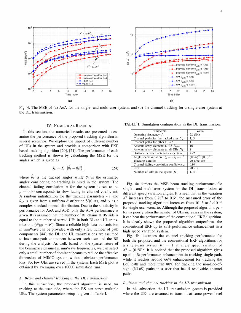
Fig. 4: The MSE of (a) AoA for the single- and multi-user system, and (b) the channel tracking for a single-user system atthe DL transmission.
IV. NUMERICAL RESULTS
In this section, the numerical results are presented to ex-amine the performance of the proposed tracking algorithm inseveral scenarios. We explore the impact of different numberof UEs in the system and provide a comparison with EKFbased tracking algorithm [20], [21]. The performance of eachtracking method is shown by calculating the MSE for theangles which is given as
Jk = E[|θt − θt|22
], (24)
where θt is the tracked angles while θt is the estimatedangles considering no tracking is hired in the system. Thechannel fading correlation ρ for the system is set to beρ = 0.99 corresponds to slow fading in channel coefficient.A random initialization for the tracking parameters θA andθD is given from a uniform distribution U(0, π), and α as acomplex standard normal distribution. Due to the similarity inperformance for AoA and AoD, only the AoA performance isgiven. It is assumed that the number of RF chains at BS side isequal to the number of served UEs in both DL and UL trans-missions (NRF = K). Since a reliable high-data transmissionin mmWave can be provided with only a few number of pathcomponents [44], the DL and UL transmissions are assumedto have one path component between each user and the BSduring the analysis. As well, based on the sparse nature ofthe beamspace channel at mmWave frequencies, we can selectonly a small number of dominant beams to reduce the effectivedimension of MIMO system without obvious performanceloss. So, few UEs are served in the system. Each MSE plot isobtained by averaging over 10000 simulation runs.
A. Beam and channel tracking in the DL transmission
In this subsection, the proposed algorithm is used fortracking at the user side, where the BS can serve multipleUEs. The system parameters setup is given in Table I.
TABLE I: Simulation configuration in the DL transmission.
Parameters ValueOperating frequency fc 28 GHzChannel paths for the tracked user Lk 1, 5Channel paths for other UEs l 1Antenna array elements at BS NBS 16Antenna array elements at all UEs Nk 8Distance between antenna elements d λ/2Angle speed variation σ2
A = σ2D = σ2 (0.25)2, (0.5)2
Tracking duration 20 time slotChannel fading correlation coefficient ρ 0.99SNR 20 dBNumber of UEs in the system K 1, 4
Fig. 4a depicts the MSE beam tracking performance forsingle- and multi-user system in the DL transmission atdifferent speed variation angles. It is seen that as the variationσ2 increases from 0.252 to 0.52, the measured error of theproposed tracking algorithm increases from 10−4 to 5x10⁻³
for single user scenario. Although the proposed algorithm per-forms poorly when the number of UEs increases in the system,it can beat the performance of the conventional EKF algorithm.It is clearly shown the proposed algorithm outperforms theconventional EKF up to 85% performance enhancement in ahigh speed variation system.
Fig. 4b illustrates the channel tracking performance forboth the proposed and the conventional EKF algorithms fora single-user system K = 1 at angle speed variation ofσ2 = (0.25)2. It is noticed that the proposed algorithm givesup to 44% performance enhancement in tracking single path,while it reaches around 66% enhancement for tracking theLoS path and more than 80% for tracking the non-line-of-sight (NLoS) paths in a user that has 5 resolvable channelpaths.
B. Beam and channel tracking in the UL transmissionIn this subsection, the UL transmission system is provided
where the UEs are assumed to transmit at same power level

7
2 4 6 8 10 12 14 16 18 20
Time index
10-5
10-4
MS
E [R
ad
2]
proposed algorithm K=1
proposed algorithm K=2
proposed algorithm K=4
EKF K=1
EKF K=2
EKF K=4
(a)
2 4 6 8 10 12 14 16 18 20
Time index
10-3
10-2
10-1
E{
|'-
|2}
proposed algorithm K=1
proposed algorithm K=2
proposed algorithm K=4
EKF K=1
EKF K=2
EKF K=4
(b)
Fig. 5: The MSE of (a) AoA for different number of UEs, and (b) its channel tracking at the UL transmission.
TABLE II: Simulation configuration in the UL transmission.
Parameters ValueOperating frequency fc 28 GHzChannel paths between each UE and the BS Lk 1Antenna array elements at BS NBS 16Antenna array elements at all UEs Nk 8Distance between antenna elements d λ/2Angle speed variation for all UEs σ2
A = σ2D = σ2 (0.35)2
Tracking duration 20 time slotchannel fading correlation coefficient ρ 0.99Averaged SNR from each UE 0 dBNumber of UEs in the system K 1, 2, 4
and received at the same time by the BS. Note that same powertransmission by the UEs is the worst case scenario due to thehigh level of inter-user interference observed at the receiver.The proposed algorithm is optimized its parameters accordingto receiving the UEs’ signals together. So that all UEs havebeen tracked jointly and simultaneously. However, the EKFalgorithm in this case is employed to track each user channelseparately in the presence of receiving signal from other UEs.The system parameters setup for the UL transmission are givenin Table II.
Fig. 5a demonstrates the MSE performance of AoA beamtracking for the single- and multi-user beamspace MIMO sys-tems while Fig. 5b illustrates the channel tracking performancefor the same system at the UL transmission. According toFig. 5a, the effectiveness of the proposed algorithm in trackingmultiple beams jointly is clearly shown with 62% performanceenhancement compared to the conventional EKF method. Aswell, the degradation in performance between different numberof UEs in the system is negligible. However, as shown inFig. 5b, the performance gap between the proposed algorithmin a single-user system and multi-user system is notablewhere there is around 90% reduction in performance betweenone-user system and two-user system. Noting that the gapbetween the proposed algorithm and the conventional EKFbased method is increased as well.
V. CONCLUSION
A novel multi-beam joint-tracking algorithm based on UKFfilter was designed for multi-user beamspace MIMO systemsusing LAA. The proposed algorithm is employed to track thechannel parameters; AoA, AoD, and channel coefficient, ofmulti-beam jointly. The algorithm avoids Jacobian and/or Hes-sian matrices computation to provide a linear estimator withoutany approximation as it is the case in the conventional EKFbased method. Two implementations were investigated for thebeam and channel tracking using the proposed algorithm: 1)single-beam tracking at the UE side in the DL transmissionin the presence of other UEs’ beams interference, and 2)multi-beam joint-tracking at the BS side in the UL trans-mission system. Note that the proposed algorithm optimizedthe sigma points spreading parameters of UKF method whichenables us to efficiently track multiple UEs simultaneously.This leads to enhancing the tracking performance by reducingoverall interference in the UL transmission. The numericalresults showed that the proposed algorithm can provide upto 85% performance enhancement in tracking performancecompared to conventional EKF based method in high mobilitysystems. The proposed algorithm can be implemented in ahighly mobile environment to enhance mobility support bydetecting changes in the channel for high-speed users. Also,the proposed algorithm is feasible for devices with limitedcomputation and processing capabilities. As a future work,performance analysis of the presented works can be utilizedin a laboratory environment.
ACKNOWLEDGEMENT
The work of H. Arslan was supported by the Scientific andTechnological Research Council of Turkey under Grant No.116E078.
8
APPENDIX AANALYSIS OF f
Given that φA = dλ sin(θk,A,l,t), φD = d
λ sin(θk,D,l,t), andUa(θk,A,l,t)a
H(θk,D,l,t)UH is equal to
Hk,l,t =
uH(ψr,0)uH(ψr,1)
. . .uH(ψr,Nr−1)
u(φA)×
uH(φD)[u(ψt,0) u(ψt,1) · · · u(ψt,Nt−1)
] (25)
Therefore, each element in the matrix can be given as
[Hk,l,t]v,c =∑q
∑i
e−j2π[qiφA−qφD+qψt,c−iψr,v ], (26)
where q = {−(Nt−1)2 , · · · , (Nt−1)
2 } and i =
{−(Nr−1)2 , · · · , (Nr−1)
2 }.Simplifying (26) as
[Hk,l,t]v,c =∑q
e−j2π[ψt,c−φD]q∑i
e−j2π[qφA−ψr,v ]i,
=∑q
e−j2π[ψt,c−φD]q sin(πNr(qφA − ψr,v)sin(π(qφA − ψr,v))
,
=∑q
e−j2π[ψt,c−φD]qfNr (qφA − ψr,v),
= f (φA, φD, ψt,c, ψr,v) ,(27)
where fN (ϕ) is the Dirichlet sinc function with a maximumof N at ϕ = 0. It is noticed that each element in Hk,l,t is asummation of Dirichlet function with a phase shift of ψt,c−φDwhich has the same capabilities of the original Dirichlet sincfunction. Therefore, the power in Hk,l,t is concentrated onlyon a small number of elements due to the power-focusingability of fN (ϕ) [29].
REFERENCES
[1] Z. Pi and F. Khan, “An introduction to millimeter-wave mobile broad-band systems,” IEEE Communications Magazine, vol. 49, no. 6, pp.101–107, 2011.
[2] R. W. Heath, N. Gonzalez-Prelcic, S. Rangan, W. Roh, and A. M.Sayeed, “An overview of signal processing techniques for millimeterwave MIMO systems,” IEEE Journal of Selected Topics in SignalProcessing, vol. 10, no. 3, pp. 436–453, 2016.
[3] S. Dogan, M. Karabacak, and H. Arslan, “Optimization of antennabeamwidth under blockage impact in millimeter-wave bands,” in 2018IEEE 29th Annual International Symposium on Personal, Indoor andMobile Radio Communications (PIMRC). IEEE, 2018, pp. 1–5.
[4] B. Pekoz, M. Hafez, S. Kose, and H. Arslan, “Reducing precoder/chan-nel mismatch and enhancing secrecy in practical MIMO systems usingartificial signals,” IEEE Communications Letters, 2020.
[5] I. Ahmed, H. Khammari, A. Shahid, A. Musa, K. S. Kim, E. De Poorter,and I. Moerman, “A survey on hybrid beamforming techniques in 5G:Architecture and system model perspectives,” IEEE CommunicationsSurveys & Tutorials, vol. 20, no. 4, pp. 3060–3097, 2018.
[6] A. F. Molisch, V. V. Ratnam, S. Han, Z. Li, S. L. H. Nguyen, L. Li,and K. Haneda, “Hybrid beamforming for massive MIMO: A survey,”IEEE Communications Magazine, vol. 55, no. 9, pp. 134–141, 2017.
[7] J. Brady, N. Behdad, and A. M. Sayeed, “Beamspace MIMO formillimeter-wave communications: System architecture, modeling, anal-ysis, and measurements,” IEEE Transactions on Antennas and Propa-gation, vol. 61, no. 7, pp. 3814–3827, 2013.
[8] Y. Zeng and R. Zhang, “Millimeter wave MIMO with lens antennaarray: A new path division multiplexing paradigm,” IEEE Transactionson Communications, vol. 64, no. 4, pp. 1557–1571, 2016.
[9] M. A. Al-Joumayly and N. Behdad, “Wideband planar microwave lensesusing sub-wavelength spatial phase shifters,” IEEE Transactions onAntennas and Propagation, vol. 59, no. 12, pp. 4542–4552, 2011.
[10] Y. J. Cho, G.-Y. Suk, B. Kim, D. K. Kim, and C.-B. Chae, “RF lens-embedded antenna array for mmWave MIMO: Design and performance,”IEEE Communications Magazine, vol. 56, no. 7, pp. 42–48, 2018.
[11] O. Quevedo-Teruel, M. Ebrahimpouri, and F. Ghasemifard, “Lens anten-nas for 5G communications systems,” IEEE Communications Magazine,vol. 56, no. 7, pp. 36–41, 2018.
[12] Y. Zeng, R. Zhang, and Z. N. Chen, “Electromagnetic lens-focusingantenna enabled massive MIMO: Performance improvement and costreduction,” IEEE Journal on Selected Areas in Communications, vol. 32,no. 6, pp. 1194–1206, 2014.
[13] T. Kwon, Y.-G. Lim, B.-W. Min, and C.-B. Chae, “RF lens-embeddedmassive MIMO systems: Fabrication issues and codebook design,” IEEETransactions on Microwave Theory and Techniques, vol. 64, no. 7, pp.2256–2271, 2016.
[14] P. Y. Lau, Z. N. Chen, and X. Qing, “Electromagnetic field distribution oflens antennas,” in Proc. Asia-Pac. Conference on Antennas Propagation,2013.
[15] M. Nazzal, M. A. Aygul, A. Gorcin, and H. Arslan, “Dictionary learning-based beamspace channel estimation in millimeter-wave massive MIMOsystems with a lens antenna array,” in 2019 15th International WirelessCommunications & Mobile Computing Conference (IWCMC). IEEE,2019, pp. 20–25.
[16] X. Wei, C. Hu, and L. Dai, “Deep learning for beamspace channel esti-mation in millimeter-wave massive MIMO systems,” IEEE Transactionson Communications, 2020.
[17] L. Yang, Y. Zeng, and R. Zhang, “Channel estimation for millimeter-wave MIMO communications with lens antenna arrays,” IEEE Transac-tions on Vehicular Technology, vol. 67, no. 4, pp. 3239–3251, 2017.
[18] X. Li, J. Fang, H. Li, and P. Wang, “Millimeter wave channel estimationvia exploiting joint sparse and low-rank structures,” IEEE Transactionson Wireless Communications, vol. 17, no. 2, pp. 1123–1133, 2017.
[19] L. Bai, L. Zhu, J. Liu, J. Choi, and W. Zhang, “Physical layer au-thentication in wireless communication networks: A survey,” Journal ofCommunications and Information Networks, vol. 5, no. 3, pp. 237–264,2020.
[20] C. Zhang, D. Guo, and P. Fan, “Tracking angles of departure and arrivalin a mobile millimeter wave channel,” in Proc. IEEE InternationalConference on Communications (ICC). IEEE, 2016, pp. 1–6.
[21] V. Va, H. Vikalo, and R. W. Heath, “Beam tracking for mobile millimeterwave communication systems,” in Proc. IEEE Global Conference onSignal and Information Processing (GlobalSIP). IEEE, 2016, pp. 743–747.
[22] S. Jayaprakasam, X. Ma, J. W. Choi, and S. Kim, “Robust beam-trackingfor mmWave mobile communications,” IEEE Communications Letters,vol. 21, no. 12, pp. 2654–2657, 2017.
[23] S. Shaham, M. Ding, M. Kokshoorn, Z. Lin, S. Dang, and R. Abbas,“Fast channel estimation and beam tracking for millimeter wave vehic-ular communications,” IEEE Access, vol. 7, pp. 141 104–141 118, 2019.
[24] Y. Fan, J. B. Li, H. Li, and C. Tian, “A stochastic framework ofmillimeter wave signal for mobile users: Experiment, modeling andapplication in beam tracking,” in Proc. 11th Global Symposium onMillimeter Waves (GSMM). IEEE, 2018, pp. 1–6.
[25] J. Lim, H.-M. Park, and D. Hong, “Beam tracking under highly non-linear mobile millimeter-wave channel,” IEEE Communications Letters,vol. 23, no. 3, pp. 450–453, 2019.
[26] D. Zhu, J. Choi, Q. Cheng, W. Xiao, and R. W. Heath, “High-resolution angle tracking for mobile wideband millimeter-wave systemswith antenna array calibration,” IEEE Transactions on Wireless Com-munications, vol. 17, no. 11, pp. 7173–7189, 2018.
[27] L. Dai and X. Gao, “Priori-aided channel tracking for millimeter-wavebeamspace massive MIMO systems,” in 2016 URSI Asia-Pacific RadioScience Conference (URSI AP-RASC). IEEE, 2016, pp. 1493–1496.
[28] Z. Wang, M. Li, X. Tian, and Q. Liu, “Iterative hybrid precoderand combiner design for mmWave multiuser MIMO systems,” IEEECommunications Letters, vol. 21, no. 7, pp. 1581–1584, 2017.
[29] A. Sayeed and N. Behdad, “Continuous aperture phased MIMO: Basictheory and applications,” in 2010 48th Annual Allerton Conference onCommunication, Control, and Computing (Allerton). IEEE, 2010, pp.1196–1203.
[30] J. Li, Y. Sun, L. Xiao, S. Zhou, and C. E. Koksal, “Fast analog beamtracking in phased antenna arrays: Theory and performance,” arXivpreprint arXiv:1710.07873, 2017.
[31] M. Medard, “The effect upon channel capacity in wireless commu-nications of perfect and imperfect knowledge of the channel,” IEEETransactions on Information theory, vol. 46, no. 3, pp. 933–946, 2000.

9
[32] J. M. Wooldridge, Introductory econometrics: A modern approach,6th ed. Nelson Education, 2016.
[33] S. Lu, L. Cai, L. Ding, and J. Chen, “Two efficient implementation formsof unscented Kalman filter,” in 2007 IEEE International Conference onControl and Automation. IEEE, 2007, pp. 761–764.
[34] C. Montella, “The Kalman filter and related al-gorithms: A literature review,” Dec. 2011. [Online].Available: https://www.researchgate.net/publication/236897001 TheKalman Filter and Related Algorithms A Literature Review
[35] S. Thrun, “Probabilistic robotics,” Communications of the ACM, vol. 45,no. 3, pp. 52–57, 2002.
[36] B. Allotta, A. Caiti, L. Chisci, R. Costanzi, F. Di Corato, C. Fantacci,D. Fenucci, E. Meli, and A. Ridolfi, “An unscented Kalman filter basednavigation algorithm for autonomous underwater vehicles,” Mechatron-ics, vol. 39, pp. 185–195, 2016.
[37] B. Allotta, A. Caiti, R. Costanzi, F. Fanelli, D. Fenucci, E. Meli, andA. Ridolfi, “A new AUV navigation system exploiting unscented Kalmanfilter,” Ocean Engineering, vol. 113, pp. 121–132, 2016.
[38] Y. Meng, S. Gao, Y. Zhong, G. Hu, and A. Subic, “Covariance matchingbased adaptive unscented Kalman filter for direct filtering in INS/GNSSintegration,” Acta Astronautica, vol. 120, pp. 171–181, 2016.
[39] A. Kallapur, M. Samal, V. Puttige, S. Anavatti, and M. Garratt, “AUKF-NN framework for system identification of small unmanned aerialvehicles,” in 2008 11th International IEEE Conference on IntelligentTransportation Systems. IEEE, 2008, pp. 1021–1026.
[40] H. Zhang, G. Dai, J. Sun, and Y. Zhao, “Unscented Kalman filter andits nonlinear application for tracking a moving target,” Optik, vol. 124,no. 20, pp. 4468–4471, oct 2013.
[41] S. G. Larew and D. J. Love, “Adaptive beam tracking with the unscentedKalman filter for millimeter wave communication,” IEEE Signal Pro-cessing Letters, vol. 26, no. 11, pp. 1658–1662, 2019.
[42] E. A. Wan and R. Van Der Merwe, “The unscented Kalman filterfor nonlinear estimation,” in Proc. IEEE Adaptive Systems for SignalProcessing, Communications, and Control Symposium. IEEE, 2000,pp. 153–158.
[43] N. Gordon, B. Ristic, and S. Arulampalam, “Beyond the Kalman filter:Particle filters for tracking applications,” Artech House, London, vol.830, no. 5, pp. 1–4, 2004.
[44] S. Han, I. Chih-Lin, Z. Xu, and C. Rowell, “Large-scale antenna systemswith hybrid analog and digital beamforming for millimeter wave 5G,”IEEE Communications Magazine, vol. 53, no. 1, pp. 186–194, 2015.


![Beamspace MIMO Prototype for Low-Complexity Gigabit/s ... · communication subspace for a line-of-sight setup isp = 4 [5]. The link length between the two DLAs is R = 2.67 m; see](https://static.fdocuments.in/doc/165x107/5f49e6ca6a20492b4c022f25/beamspace-mimo-prototype-for-low-complexity-gigabits-communication-subspace.jpg)