JOINT RESEARCH DOCTORATE IN FUSION SCIENCE AND ENGINEERING …
150
1 UNIVERSITA’ DEGLI STUDI DI PADOVA CENTRO INTERDIPARTIMENTALE “Centro Ricerche Fusione" UNIVERSIDADE TÉCNICA DE LISBOA JOINT RESEARCH DOCTORATE IN FUSION SCIENCE AND ENGINEERING CYCLE XXVII (2012/2014) PhD THESIS THEORETICAL STUDIES OF RESISTIVE WALL MODE AND FISHBONE-LIKE EXTERNAL KINK MODE IN RFP PLASMAS AND COMPARISON WITH TOKAMAKS Coordinator : Chiar.mo Prof. Paolo BETTINI Supervisor(s): Chiar.mo Prof. Piero MARTIN Chiar.mo Dr. Shichong GUO Doctoral Student: Xinyang XU
Transcript of JOINT RESEARCH DOCTORATE IN FUSION SCIENCE AND ENGINEERING …
1
UNIVERSITA’ DEGLI STUDI DI PADOVA CENTRO INTERDIPARTIMENTALE “Centro Ricerche Fusione"
UNIVERSIDADE TÉCNICA DE LISBOA
JOINT RESEARCH DOCTORATE IN FUSION SCIENCE AND ENGINEERING CYCLE XXVII (2012/2014)
PhD THESIS
THEORETICAL STUDIES OF RESISTIVE WALL MODE AND FISHBONE-LIKE EXTERNAL KINK MODE IN RFP PLASMAS AND COMPARISON WITH TOKAMAKS
Coordinator : Chiar.mo Prof. Paolo BETTINI
Supervisor(s): Chiar.mo Prof. Piero MARTIN Chiar.mo Dr. Shichong GUO Doctoral Student:
Xinyang XU


iii
October, 2014


v
Abstract
The theoretical studies on the Resistive Wall Modes (RWM) and non-resonant Fishbone-Like External kink Mode (FLEM) in Reversed Field Pinch (RFP) plasmas are reported, and comparison is made with the Tokamaks. Various features of these two instabilities in the RFP and Tokamak configurations are investigated in order to provide an in-depth understanding on the mode physics. The toroidal MHD-kinetic hybrid stability code MARS-K was applied to the studies, which takes into account the drift kinetic effects of thermal particles as well as the isotropic/anisotropic energetic particles (EPs). The RWM behaviour in the RFP plasmas with shaped cross section is investigated first, and it is found to be quite different from Tokamaks. Furthermore, the EPs effects on RWMs are studied in both RFP and Tokamak plasmas, considering both isotropic and anisotropic energetic ions (EIs). Besides the RWMs, this study also finds the triggering of the FLEM instability, which is driven by the precessional motion of energetic ions. FLEMs can coexist or couple with the RWMs, depending on the plasma parameters.
The MARS-K code is also applied to the study of the RWM stability in the JT-60SA Tokamaks, and the preliminary results are provided.

vi
Prefazione
Vengono presentati studi teorici sui Resistive Wall Modes (RWM) e sui non resonant Fishbone-Like External kink Modes (FLEM) presenti nei plasmi di tipo RFP (Reversed Field Pinch) e confrontate con il caso Tokamak. Vengono analizzate le caratteristiche di queste due instabilità nelle due configurazioni, in modo da ottenere una visione approfondita dei fenomeni fisici alla loro base. Il codice toroidale ibrido di stabilità MHD-cinetica MARS-K è stato impiegato in questi studi; esso prende in considerazione gli effetti cinetici di drift delle particelle termiche così come le particelle energetiche (EP, Energetic Particles) isotropiche/anisotropiche. Anzitutto è stato investigato il comportamento dei modi RWM nei plasmi RFP con sezione non circolare, che è stato scoperto essere molto diverso da quello nei Tokamak. Oltre a questo sono stati studiati gli effetti delle EP sui modi RWM nei plasmi sia RFP che Tokamak, considerando gli ioni energetici (EI, Energetic Ions) sia isotropi che anisotropi. Oltre agli RWM, questo studio ha individuato le cause di innesco delle instabilità FLEM, che sono provocate dal moto di precessione di ioni energetici. Le instabilità possono coesistere o essere accoppiate agli RWM, a seconda dei parametri di plasma.
Il codice MARS-K è stato applicato anche allo studio della stabilità degli RWM nel tokamak JT-60SA, vengono illustrati i risultati preliminari.
i
Summary The aim of the nuclear fusion research is to obtain the new energy resource, which is clear, safety and sustainable, as the alternative energy of the conventional energy. The research has been carried out in many countries and many years through experimental analysis and physical demonstration.
One of the achievable approaches to realize the controlled fusion device is the magnetic confinement fusion. The International Thermonuclear Experimental Reactor (ITER) is the biggest and most advanced fusion reactor in the world, which is designed and under building, based on the Tokamak configuration in order to achieve the burning plasma successfully. The Reversed Field Pinch (RFP), with high plasma current performance (~2MA in the RFX-mod experiment), is another magnetic confinement configuration, as an alternative fusion experimental device. The Magnetohydrodynamic (MHD) instabilities are very important behaviors in both RFP and Tokamak configuration, which limits the achievements of the high performance and steady-state operation in the present experiments and even cause the terrible destroy to the devices.
In this thesis works, the theoretical studies on the instabilities of the Resistive Wall Mode (RWM) and the Fishbone-Like External kink Mode (FLEM) are carried out for both RFP and Tokamak (circular cross section with similar geometry) magnetic configurations. Various features of the RWM and FLEM instabilities between the two configurations are compared in order to provide an in-depth understanding on the mode physics. The MHD-kinetic hybrid toroidal stability code MARS-K was applied to the studies, which takes into account the drift kinetic effects of thermal particles as well as the isotropic/anisotropic energetic particles (EPs).
Both RWM and FLEM originate from the ideal external kink mode (one of the most important MHD instabilities). As well known, the external kink mode can be stabilized by an ideally conducting wall located sufficiently close to the plasma surface. However, if the ideal wall is replaced by a resistive wall, the mode converts to a slowly growing RWM instability with the growth rate in the order of tw
-1 (tw is the wall penetration time). The RWM instability causes a global distortion of the plasma that often results in a major disruption, thus it is probably

ii
the most prominent obstacle for achieving the high beta plasma regime in the operation of the advanced fusion devices. As presented by many previous studies, the stabilization of RWMs can be performed (actively) by the feedback control system; or (passively) by the plasma rotation with various damping mechanisms. Particularly, RWM can be stabilized in tokamaks at very slow (even vanishing) plasma rotation by the kinetic damping produced from the wave-particle resonances. These kinetic effects have been suggested by many experimental and theoretical studies as one of the most effective damping machnisms. Therefore the RWM study cannot be solely treated by the ideal MHD theory, a drift kinetic description is necessary to be introduced in the study.
The energetic particle physics is an important issue to be studied in order to understand the behavior of the burning plasmas which represents the primary scientific challenge faced by ITER and fusion research in general. E.g., in D–T plasmas, such as foreseen for ITER, self-heating is provided by the alphas generated at 3.5MeV by the D–T fusion reactions. In addition, other fast or energetic ions with energies well above the thermal distribution of the plasma bulk, are generated by neutral beam injection (NBI) and ion cyclotron resonant heating (ICRH). These are expected to play major role in achieving optimal burning plasma scenarios with external heating and/or current drive. On the other hand, the Energetic Particles (EPs) may interact with the bulk plasma waves and instabilities, which possibly lead to destabilize/stabilize the existing turbulence in the bulk plasma, even to excite a new type of instabilities, which may result to redistribution and losses of EPs. In this thesis, the EPs effect on the RWM instabilities have been studied for both RFP and Tokamak plasmas. Furthermore, another branch of external kink mode -- the Fish bone Like External kink Mode (FLEM) driven by the precession drift motion of the energetic particles is investigated in the two configurations. The nature and the physics of the FLEM are clarified by numerical analysis. This subject is also much relevant to the experimental observation such as in JT-60U, DIII-D and MST et al.
The present thesis is organized in five parts as shown in the following:
Chapter 1 is an introduction to the concept of the nuclear fusion and the magnetic confinement devices (the Tokamak and the RFP). The definitions and the basic physics of the MHD instabilities are also introduced in both plasma configurations, particularly the RWM and fishbone-like mode instabilities.
iii
In the chapter 2, the formulations of the theoretical model related to the MARS-K code, are introduced. In order to gain better physical understanding, we compute various components of the quadratic energy form, for both fluid and drift kinetic energy perturbations, from the self-consistent solution. The equilibrium profiles of the pressure and the density for each species (including the thermal particles and the EPs), in both RFPs and tokamaks, is also introduced.
Chapter 3 studies the shaping effects on Magnetohydrodynamic (MHD) stabilities in reversed field pinch (RFP) plasmas by using the MHD-kinetic hybrid toroidal stability code MARS-K, where both elongation and triangularity are taken into account. In the Tokamak plasmas, the D-shape cross-section often helps to increase the favorable curvature region which is inherently a stabilizing factor for some MHD modes. In contrast, the shaped cross section of the RFP plasmas leads to a lower ideal wall beta limit than that of the circular one; and does not bring an appreciable benefit in kinetic damping on RWMs. The major physics reason is the strong poloidal field in the RFP, which plays an important role in the poloidal mode coupling and the particle dynamics, and in particular, prevents the access to a substantially improved good averaged curvature by shaping.. Apart from the RWM study, the stability boundary of the linear resistive tearing mode in shaped RFP plasmas is computed and compared with that of the circular case. In addition, the bootstrap currents are calculated for both circular and shaped RFP plasmas. Overall, the results of these studies indicate that the current circular cross section is an appropriate choice for RFP devices.
In the chapter 4, the kinetic effects of the EPs on Resistive Wall Mode (RWM) are studied in both Reversed Field Pinch (RFP) and Tokamak configurations. It is found that the EPs can play stabilizing role on the RWM by their precession drift motion, which resonates with the mode under the plasma rotation. However, the precession of EP may cancel the kinetic damping induced by thermal particles in bulk plasma, even through the RWMs can be stabilized (under certain flow velocity) by the kinetic effects of each species alone. Therefore, with the presence of the EPs in the plasma, the condition of the stabilization of RWMs by kinetic damping depends on the parameters of the two species. Appropriately choosing the NBI parameters (energy, pitch angle of injection et al) may possibly minimize the cancellation effects. The understanding of the results is provided by the detailed analysis of the kinetic energy components contributed from each species.

iv
Furthermore, the effects of the anisotropic distribution and the variation of the
birth energy of EPs are investigated.
In Chapter 5, The Fish-bone like external Kink mode (FLEM) instability driven by the precession drift motion of the trapped Energetic Particles is investigated in both RFP and Tokamak plasmas. In RFP plasmas, the non-resonant FLEM instability is predicted. When a sufficient fraction of EPs presents in the plasma
and the condition of resonance d rn n is satisfied (where d is the
precessional frequency of the trapped EPs, r is the mode frequency and the
plasma rotation frequency), the originally stable non- resonant ideal kink mode (stabilized by the sufficiently closed ideal conducting wall) can be driven to be unstable by the precessional drift resonance of the EPs. The mode frequency, therefore, is much higher than RWMs, around the range of the ideal MHD time scale (Alfven frequency), and varies with the plasma rotation frequency. In general, the instability of FLEM does not depend on the wall resistivity. However, the wall position could significantly affect the mode property. The kinetic effect of the thermal particles (transit resonance of passing particles) plays a stabilizing role on FLEMs. With the presence of EPs in the plasma, the FLEM and the RWM can coexist or couple to each other, depending on the plasma parameters.
The same type of the instability is observed in the Tokamak plasmas, where the dominant non-resonant external kink mode (e.g. m=1, n=1) couples with the resonant external kink modes (e.g. m=2, 3, n=1). The similar nature to what in RFPs is observed. Nevertheless, in Tokamak the frequency of FLEM is much lower than what in RFP due to the lower precession frequency of EPs in a Tokamak than in RFP (with similar geometry). Furthermore, the Landau damping of the transit resonance by the passing thermal particles in Tokamak is weaker than in RFP due to the longer connection length in Tokamaks.
In the Chapter 6, the stability of the RWM by considering the plasma rotation for the JT-60SA Tokamak has been studied, by using the MARS-K code, in the fluid theory with the ions acoustic Landau damping. The equilibrium data of the JT-60SA scenario #5-1 is adapted as input of the MARS-K code. The ideal wall beta limit and the no-wall beta limit set by the ideal kink mode/resistive wall mode are calculated first. Secondly, the stabilization of the RWM with plasma rotation has been studied. It is found that the stabilizing effect contributed by the ion acoustic Landau damping is mainly located at the region q>3 (q is the safety factor). Finally,

v
the stability windows of the RWMs with various plasma rotation frequencies are also calculated. The results indicate that the stability window is enlarged with the increased plasma rotation frequency, and sensitive to the rotation profile.

vii
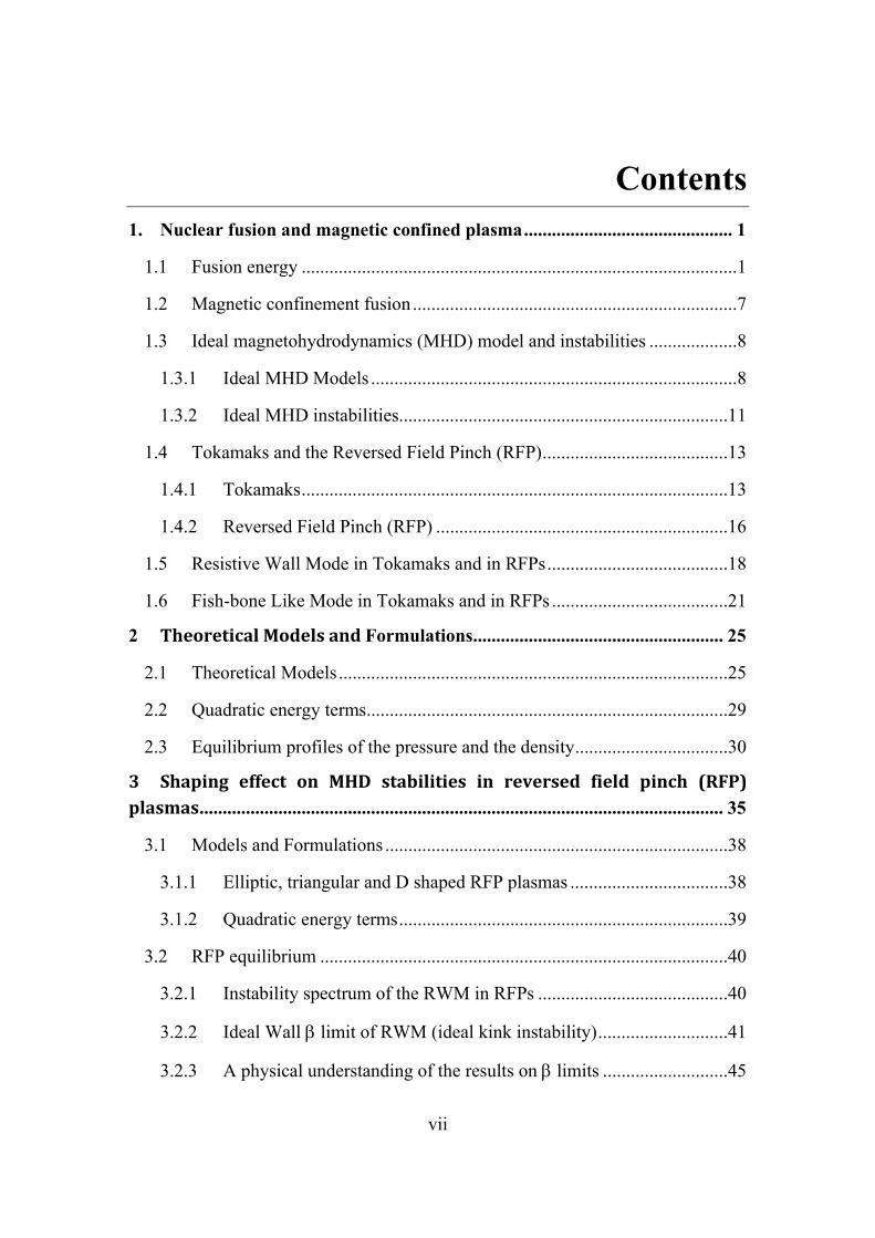
Contents 1. Nuclear fusion and magnetic confined plasma ............................................. 1
1.1 Fusion energy .............................................................................................. 1
1.2 Magnetic confinement fusion ...................................................................... 7
1.3 Ideal magnetohydrodynamics (MHD) model and instabilities ................... 8
1.3.1 Ideal MHD Models ............................................................................... 8
1.3.2 Ideal MHD instabilities.......................................................................11
1.4 Tokamaks and the Reversed Field Pinch (RFP) ........................................13
1.4.1 Tokamaks ............................................................................................13
1.4.2 Reversed Field Pinch (RFP) ...............................................................16
1.5 Resistive Wall Mode in Tokamaks and in RFPs .......................................18
1.6 Fish-bone Like Mode in Tokamaks and in RFPs ......................................21
2 TheoreticalModelsandFormulations ...................................................... 25
2.1 Theoretical Models ....................................................................................25
2.2 Quadratic energy terms ..............................................................................29
2.3 Equilibrium profiles of the pressure and the density .................................30
3 Shaping effect on MHD stabilities in reversed field pinch (RFP)plasmas ................................................................................................................. 35
3.1 Models and Formulations ..........................................................................38
3.1.1 Elliptic, triangular and D shaped RFP plasmas ..................................38
3.1.2 Quadratic energy terms .......................................................................39
3.2 RFP equilibrium ........................................................................................40
3.2.1 Instability spectrum of the RWM in RFPs .........................................40
3.2.2 Ideal Wall limit of RWM (ideal kink instability) ............................41
3.2.3 A physical understanding of the results on limits ...........................45

viii
3.3 RWM instability spectrum in RFP plasma ................................................49
3.3.1 Multiple trapping regions ...................................................................49
3.3.2 Kinetic damping on RWMs in shaped RFPs ......................................52
3.4 Shaping effects on resistive modes ...........................................................57
3.5 Shaping on Bootstrap current in RFPs ......................................................60
3.6 Summary ....................................................................................................62
4 The kinetic effect of the Energrtic Paricles (EPs) on the RWM instability in RFP plasma, compared with the Tokamaks ................................................. 65
4.1 Kinetic effects of EPs with isotropic distribution on RWMs in RFP plasma ..................................................................................................................67
4.1.1 The equilibrium parameters ................................................................67
4.1.2 Dispersion relation of the RWMs .......................................................68
4.1.3 Stabilization of the kinetic effect of the EIs, compared with the thermal particles ...............................................................................................69
4.1.4 Stabilization of the kinetic effect of the EIs with its different birth energy ............................................................................................................74
4.2 Kinetic effects of EPs with anisotropic distribution on RWMs in RFP plasma ..................................................................................................................75
4.3 Kinetic effects of EPs with isotropic distribution on RWMs in Tokamak plasma ..................................................................................................................77
4.4 Summary ....................................................................................................81
5 TheExcitationoftheFishbone‐LikeExternalModeinbothRFPandTokamakconfigurations................................................................................... 85
5.1 Kinetic effects of EPs with isotropic distribution on FLEMs in RFP plasma ..................................................................................................................86
5.1.1 Physical understanding .......................................................................86
5.1.2 The characteristic of the FLEM in the RFP plasma ...........................89

ix
5.2 Kinetic effects of EPs with isotropic distribution on FLEMs in Tokamak plasma ................................................................................................................101
5.3 Summary ..................................................................................................108
6 RWM study in JT-60SA advanced Tokamak ........................................... 111
6.1 Model and Equilibrium............................................................................111
6.2 Predicted JT-60SA results .......................................................................114
Conclusions ......................................................................................................... 119
Bibliography ....................................................................................................... 125
Publications ......................................................................................................... 131
Acknowledgements ............................................................................................. 133

Nuclear fusion and magnetic confined plasma
1
Equation Chapter (Next) Section 1
Chapter 1
1. Nuclear fusion and magnetic confined plasma
In this capter, an introduction of unclear fusion and magnetic confined fusion plasma is given. We focus on two configurations of magnetic confinement devices: tokamak and Reversed Field Pinch (RFP). The strongest instabilities which are described by the magnetohydrodynamic model of the plasma (MHD instabilities) are introduced in both magnetic confinemant configurations. In particular, Resistive Wall Mode (RWM) and Fish-bone Like Mode (FLM) which are the macroscopic MHD instabilities are described. The discussions of both two modes are the main subject in this thesis work.
1.1 Fusionenergy
Energy is the cornerstone of social development. Recalling the development of human society, every efficient development and utilization of new energy resources, gave society a new leap forward. Energy people use today, such as coal, oil, natural gas, etc, creats great wealth for human society. However, with the depletion of non-renewable resousces and increasingly serious pollution problems, this traditional fuel resousces has slowly become an obstacle to sustainable development in the future. To face with the depletion of resources, a wide variety of energy sources such as wind, geothermal, tidal energy, etc, have been found, but these new energys which have their limitations, can not become the mainly energy development. With the successful experiment of the atomic bomb, the principle of nuclear fission energy has been known and used by more and more country. Nuclear fission energy is through the fission of heavy metals (U235), which splits into lighter unclei and releases a lot of energy. However, the reserves of the fission fuel (U235) and other heavy fuel on earth are also limited, and the potentially dangerous exists, due to the radioactive nuclear fuel and nuclear waste. As has happened in history, Chernobyl event and Fukushima Nuclear Disaster in

2
Japan remind us the safety problem of nuclear fission. For the development of human society, a new energy which is clean, sustainable, safe and high efficient has become the focal point of today's energy problems. With the development of science and technology, nuclear fusion is expected to become completely solve the problem of energy.
Contrary to nuclear fission, nuclear fusion is a nuclear reaction in which light nuclei collides to form a new type of heavy nuclei and releases the energy during the process. The mainly light elements are the hydrogen (H), deuterium (D) and tritium (T) which are the isotropes of H. During the reaction of fusion, light nuclei need very high speed to overcome the Coulomb force and to be in a very close region. In this region, the short-range nuclei force is much larger than the Coulomb force, and this force pulls the nuclei together. For larger elements, the nuclei can not be close sufficiently, and energy is not released, or even absorbed during the process. In the reaction of nuclear fusion, the matter is no longer conserved. The energy is released in the form of the energetic particles and gamma rays due to the mass defect. This transformation can be described by the Einstein famous relation:
2E mc (1.1)
In the equation (1.1), m is the mass defect, E is the energy released or absorbed
by the mass defect. There are three mainly type of fusion reaction, which are the D-D reaction, the D-T reaction, the D-He3 reaction. The D-D reaction is the most difficult to initiate, and this reaction has two branches. The D-T reaction is the easiest one to initiate, which make it major choice for fusion experiment. These reactions are written as following [1]:
17.6D T n MeV (1.2)
3 3.27D D He n MeV (1.3)
4.03D D T p MeV (1.4)
3 18.3D He p MeV (1.5)

Nuclear fusion and magnetic confined plasma
3
Figure 1.1: Velocity averaged cross section for D-D, D-T, D-He3 reaction versus
temperature (KeV)
In the figure 1.1, it shows the velocity averged cross section versus the temperatue (keV), for the D-D reaction, the D-T reaction and the D-He3 respectively. All three reactions can initiate with high sufficiently collision rate. The lowest temperature required for three reaction is in the temperature region 10~100keV. In this region, all the fuels of reaction are the fully ionized gas, which is the fourth state of matter. The electrostatic charges of ions and electrons are conserved, resulting in a quasi-neutral gas so called plasma. For maintaining the plasma temperature, enhance maintianing the collisions sufficiently to realize the reaction condition, the fuel matter confinement is required. There are two major branches of confinement method which is magnetic confinement fusion (MCF) and the inertial confinement fusion (ICF).
The magnetic confinement approach [2] is using the magnetic field to confine the fusion fuel in the plasma form. This magnetic field has a closed geometry, and confines the charged particles in a sufficiently long time scale, due to the Lorentz force. In this thesis, the study will focus on the magntic confinement fusions.
The inertial confinement approach [3] is heating and compressing the fuel toget in a small region, usually in the form of fuel pellets or/and very high power laser. If heating and compressing is high enough, the fusion reaction can be achieved.

4
In the D-T reseach, there is a chemical element that can be used for breeding the Trituim, in particular, breeding the Trituim in the blancket surrounding the D-T reaction region. The reaction equations are:
63 ( ) 4.8Li n slow T MeV (1.6)
73 ( ) 2.5Li n fast T MeV (1.7)
Power provided by fusion reaction can per unit volume Pn can be writen as equation (1.8), forcing on the magnetic confinement D-T fusion in this thesis [4].
21
4nP En (1.8)
Where E is the energy released by the fusion reaction, which is 17.6MeV for the
D-T reaction. <> is the reaction rate, shown in the figure (1.1), it includes the
reaction cross-section and the relative velocity . The n is particle density of fuel,
and which is assumed to be half of the density of electrons (nT=nD=0.5ne).
There is continus loss energy PL from plasma, which needs plasma heating PH to maintain the power banlance in the fusion reactor:
H LP P P (1.9)
3L
E E
W nTVP
(1.10)
In equation (1.10), V is the plasma volume, 3T/2 is averaged plasma temperature
per degree of freedom, W is the total energy in the plasma and E is the energy
confinement time which is determined by from experimently known quantities. In a D-T reaction, four fifths of the fusion energy is carried by the neutrons (14.1MeV) which can not be confined and are converted to electric power. And
the rest energy is carried by the -particles, which can be confined by the
magnetic field and transfers their energy E (3.52MeV) to plasma thought
collisions. Thus in equation (1.9), the total power P released by the fusion
reaction in the plasma volume is modified by a factor 0.2.

Nuclear fusion and magnetic confined plasma
5
In order to achieve a desirable fusion reactor, the energy released by -particles
can be completely sustained by the internal heating, which is called ignition. The energy balance is rewritten as:
12E
Tn
E v
(1.11)
In addition, there are a lot of radiation losses in the fusion reactor, and usually bremsstrahlung radiation is the largest loss due to the Coulomb collisions. The loss
power per unit volume can be described by:
2
2 1/2 ,i i
ib b eff eff
e
n ZP C Z n T Z
n
(1.12)
Where the Cb is a constant parameter and Zeff is the effective charge. For pure D-T reaction, Zeff is equal to 1.0. Considering the bremsstrahlung radiation loss, the
equation (1.11) can be modified, which is called Lawson `s criterion:
123
4E b eff
En T v C Z T
(1.13)
Figure 1.2 The curve nE for Lawson`s criterion of D-T reactions versus temperature T.
6
As shown in figture (1.2), this nE curve has the minimum value at Ti~25keV and
the requirement for ignition is:
20 31.5 10E in T m s (1.14)
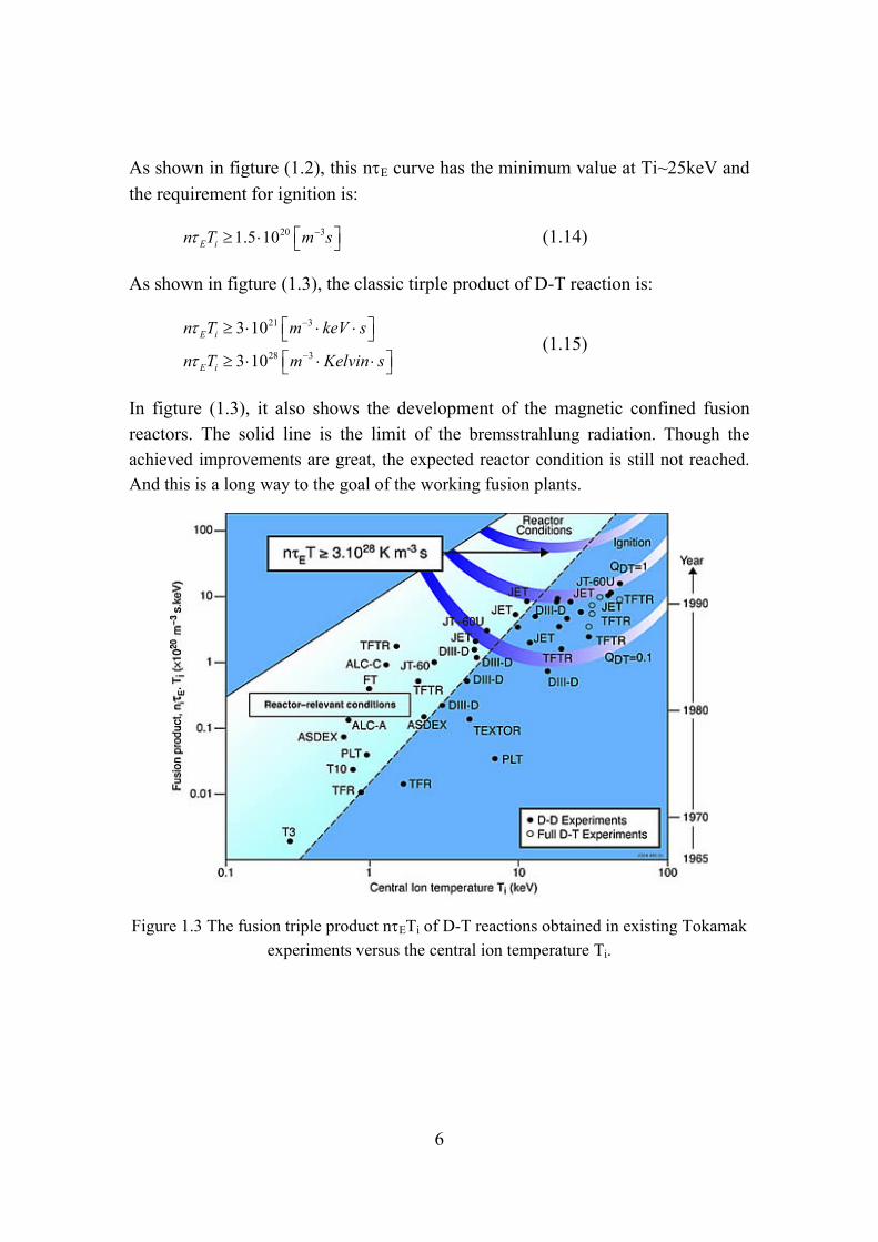
As shown in figture (1.3), the classic tirple product of D-T reaction is:
21 3
28 3
3 10
3 10
E i
E i
n T m keV s
n T m Kelvin s
(1.15)
In figture (1.3), it also shows the development of the magnetic confined fusion reactors. The solid line is the limit of the bremsstrahlung radiation. Though the
achieved improvements are great, the expected reactor condition is still not reached.
And this is a long way to the goal of the working fusion plants.
Figure 1.3 The fusion triple product nETi of D-T reactions obtained in existing Tokamak
experiments versus the central ion temperature Ti.

Nuclear fusion and magnetic confined plasma
7
1.2 Magnetic confinement fusion
Magnetic confinement fusion is a toroidal plasma confinement system, due to the Lorentz force. This force is avoiding the plasma escape to the system boundary (wall outside the plasma). The equilibrium of the pressure in the system must be satisfied, which is including the plasma pressure and the magnetic pressure producted by the magnetic feild. The mainly magnetic field is the toroidal field; however the plasma can not be confined well by this field alone. Thus the other important magnetic field, which is called the poloidal field, is necessary.
Figure 1.4 Toroidal (r, , ) and cylindrical (R, , Z) coordinations in the toroidal
configuration.
For the research of magnetic confined plasma in the torus configuration, the toroidal coordination is defined, as shown in the figure (1.4). Where the r is the radius, the R0 and a are the major and minor radius of the torus respectively, and
the b is the position of wall outsider plasma. The is the poloidal angle and the
are the toroidal angle, in which direction the poloidal magnetic field BP and toroidal mangetic field BT are defined. In plasma fusion devices, the magnetic line is in the helical path and lies on a set of closed toroidal surface.
There is an important quantity [6], which is shown in fomular (1.16) and
describes the plasma confinement efficient by the magnetic field. Due to the
economics and technology, people desires high value of . However, the
maximum value of is limited by the equilibrium balance and the MHD

8
instabilities (which will be discussed in the section 1.3.2). The definition of the
value is:
20/2
P
B
(1.16)
Where <P> and <B2>/20 is the averged plasma pressure and the magnetic field
pressure over the total plasma volume, 0 is the vacuum permeability. Usually,
with respect to each component of magnetic field BP and BT, the value is
separated to the poloidal P and the toroidal T.
The other important quantity is the safety factor q, which describes how much toroidal turns in the magnetic line are per poloidal turn. It determines the instability, in particular the MHD instabilities. For a large aspect configuration (a<<R0), it is given by:
0
( )rB
q rR B
(1.17)
In this thesis, we focus on both the Tokamaks and Reversed Field Pinchs (RFPs) configurations, which have different q profiles and instabilities. It will be shown in the following sections.
1.3 Idealmagnetohydrodynamics (MHD) modelandinstabilities
1.3.1 IdealMHDModels
The ideal magnetohydrodynamics model is a set of single-fuild equations, which describes the macroscopic behaviors in a fusion reactor configuration. It is reduced from the two-fluid mode by introducing appropriate fluid variables and scale assumptions. Due to the MHD instabilities, many terrible disruptions occur, which leads to catastrophic loss of plasma rapidly. The MHD model is thus important for MHD instability research and optimizing the magnetic configuration in fusion reactor, helping people find a continus, steady state model of operation. The MHD model is including the mass conservation equation, the momentum equation, the energy equation, the Maxwell`s equations and the ideal Ohm`s law. The equations are given by [6]:
0t
v (1.18)

Nuclear fusion and magnetic confined plasma
9
dp
dt
vJ B (1.19)
0d p
dt
(1.20)
t
B
E (1.21)
0 B J (1.22)
0 B (1.24)
0 E v B (1.25)
Where the electromagnetic variables are the electric field E , the magnetic field B ,
and the current density J . The fluid variables are the mass density , the fluid
velocity v , and the pressure p . Also, =5/3 is the ratio of specific heats and
/ /d dt t v is the convective derivative.
Since the main goal of ideal MHD is the investigation of macroscopic phenomena, the length scale of interest correspond to the macroscopic dimensions of the
plasma is the plasma radius a, denoted by ~L a , while the typical time scale of
MHD interest is the ion thermal transit time across the plasma ( ~ /iTa V ). This
leads to a characteristic velocity 1/2~ 2 /
iT i iu V T m (the ion sound speed), which is
the fastest macroscopic speed that the plasma can achieve. And the time scale is characteristic of many MHD plasma instabilities and represents the fastest time scale in which macroscopic plasma motion can occur. It should be noted that certain MHD waves and other phenomena can have time scales somewhat faster or
slower than /iTa V . In determing the scaling relations it is helpful to introduce the
characteristic MHD frequency and wave number k as follows [6]:
~ ~ iTV
t a
, (1.26)
1~ ~k
a , (1.27)
and, similarly, the resulting velcotiy

10
~ ~ Tiv Vk
. (1.28)
Furthermore, there is additional information to be introduced by examining the conditions for validity. This provides insight into which specific phenomena are not accurately described by ideal MHD. And it also indicates that those phenomena will be reliably treated even when the overall validity conditions are violated. The dimensionless variables are given by:
Liry
a (1.29)
1/2
iT iii
e
Vmx
m a
(1.30)
Where /iLi T cir V is the ion gyro radius, ii is the collision time due to the ion-ion
interaction, im and em are ion and electron masses respectively. Three independent
conditions which are described by the dimensionless variables must be satisfied for ideal MHD to be valid:
(1) High collisionality 1x
(2) Small gyro radius 1y
(3) Small resistivity 2 / 1y x
As known, the the conditions of small gyro radius and small resistivity are well satisfied for plasmas of fusion interest. Note however, that the high collisionallity assumption is never satisfied. The region of completely valid MHD model is not including the fusion interest. This disconcerting conclusion is, however, inconsistent with the overwhelming empirical evidence demonstrating that ideal MHD provides a very accurate description of most macroscopic plasma behavior. As result, it suggests the introduction of a modified MHD model, collisionless MHD. Comparing the two modes, the biggest differents are the parallel part of momentum equation and the energy equation. For momentum equation, the perpendicular components provide an excellent description of plasma in either the collision-dominated or collision-free regimes. The parallel component treated by ideal MHD models is very inaccurate. This is because of the anisotropic plasma motion in a given magnetic field line, and in a collisionless plasma, the magnetic field plays a collision role in the perpendicular motion. However, due to the MHD
incompressibility of most MHD instabilities, both p and ||p will not change
Nuclear fusion and magnetic confined plasma
11
significantly from their initial values during the increment t . From conservation
of mass relation, the incompressibility is equivalent to 0 v . So the collision-dominated and conllision-less equations of state are identical due to the incompressible motions. Consequently, both models make very similar predictions, and it is accurate to use the ideal MHD models in both collision-dominated and conllision-less regimes.
1.3.2 IdealMHDinstabilities
There are three main classification schemes, distinguishing and describing the ideal MHD instabilities. These classification schemes are 1) internal and external modes, 2) pressure-driven and current-driven modes and 3) conducting wall and no wall configuration. [1]
1) internal and external modes
The first classification scheme distinguishes between internal and external instabilities. Assuming that a well-confined plasma equilibrium separated from the first wall by a vacuum region exists, this distinction is based on if or not the surface of the plasma moves as the instabilities growing. The internal mode is a fixed boundary mode, and plasma surface is fixed in place. These instabilities occur purely inside the plasma and the place constraints in the shape of the pressure and current profiles. Often they do not lead to catastrophic loss of plasma but can result in important experimental operational limits or enhanced transport. External mode, which is free-boundary modes on the other hand, involves motion of the plasma surface, and hence the entire plasma. This motion leads to a plasma which is striking the first wall. The external modes are particularly dangerous in the fusion plasma, and it must be avoided in general.
2) pressure-driven and current-driven modes
The second way to classify plasma instabilities is due to the driving source. In general, a plasma has both perpendicular and parallel currents and each can drive pressure-driven and current-driven instabilities respectively. The classification system for these instabilities is as follows.
Since p J B in equilibrium, instabilities driven by perpendicular currents are
often called “pressure-driven” modes. Actually, it is a combination of the pressure gradient and the field-line curvature that drives the instabilities. The curvature of

12
the field lines can be favorable, unfavorable, or oscillate with respect to stability. The choice depends upon which way the radius of curvature vector points as compared to the direction of the pressure gradient. Instabilities driven primarily by the pressure gradient are usually further subclassified into one of two forms: the “interchange mode” or the “ballooning mode”. Pressure driven instabilities are
usually internal modes and set one important limit on the maximum stable that
can be achieved in a fusion plasma.
Instabilities driven by the parallel current are often called “current-driven” modes.
These instabilities can exist even in the limit of low , a regime where all
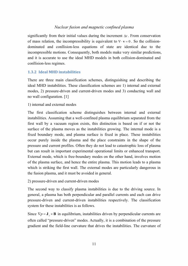
pressure-driven modes are stable. In this regime, current-driven instabilities are often called “kink modes” because the plasma deforms into a kink like shape. Kink modes can be either internal or external. The external kink mode sets an important limit on the maximum toroidal current that can flow in a plasma. The physical picture of the kink mode is shown in figure (1.5).
In certain situations, the parallel current and pressure gradient (perpendicular current) combine to drive an instability, often referred to as the kink mode. This is usually the most dangerous mode in a fusion plasma. It sets the strictest limits on the achievable pressure and current. Furthermore, it is an external mode, implying that violation of the stability boundary can lead to a rapid loss of plasma energy and plasma current to the first wall.
3) conducting wall and no wall configuration
The last classification scheme is focused on if a perfectly conducting wall is required or not. A close fitting perfectly conducting wall can greatly improve the stability of plasma against external kink modes. Since these modes set the strictest stability limits it would be highly desirable to avoid such modes by means of a
perfectly conducting wall. The resulting gains in the and current limits due to
wall stabilization are substantial, and may be mandatory for reactor viability in certain magnetic configurations.
Maintaining an ideal conducting wall close to the plasma can be realized in a real experiement or reactor. The wall must be resistive, and this subjects the plasma to the resistive wall mode (RWM). Based on the simple mechanical analog, the presence of a resistive wall has no effect on the stability boundary of a plasma without a wall. In other words, while a perfectly conducting wall can raise the
Nuclear fusion and magnetic confined plasma
13
stability limit above that of the no-wall case, a resistive wall leaves the stability boundary unchanged and only reduces the growth rate. The possibility of stabilizing the RWM by means such as feedback and kinetic damping is a critical issue. This is because in certain configuration like RFP requires a conducting wall
even at =0 since they carry a large current, and the requirement of higher value of
also needs the stability of the RWMs in tokamaks.
Figure 1.5 Diagram of the kink instability.
1.4 TokamaksandtheReversedFieldPinch(RFP)
1.4.1 Tokamaks
Tokamka devices have the very strong toroidal magnetic field BT and the much weaker poloidal magnetic field BP (BT>>BP), as shown in the figure (1.6). The safety factor q is usually increasing along the radius (q(0)<q(a)) shown in the figure (1.7). The core value of safety value q(0) needs to be larger than unit (1<q(0)<q(a)) due to the MHD instabilities discussed in the above sections. If q(a)<1, the MHD instabilities are induced, which is a current-driven external mode with the toroidal mode number m=1 (most dangerous). This critical condition is called Kruskal-Shafranov Limit. Furthermore, if q(0)<1<q(a), the resonance surface q=1 is inside the plasma, which leads to the current-driven (1,1) internal kink mode. This instability causes the “sawthooth” oscillations, and the “fish-bone” oscillations due to the neutral beam injetction. Both cases lead to limit the maximum value of the plasma current and even cause the disruptions. Due to the toroidaicity, the quantitative changes for the pressure-driven modes is induced,
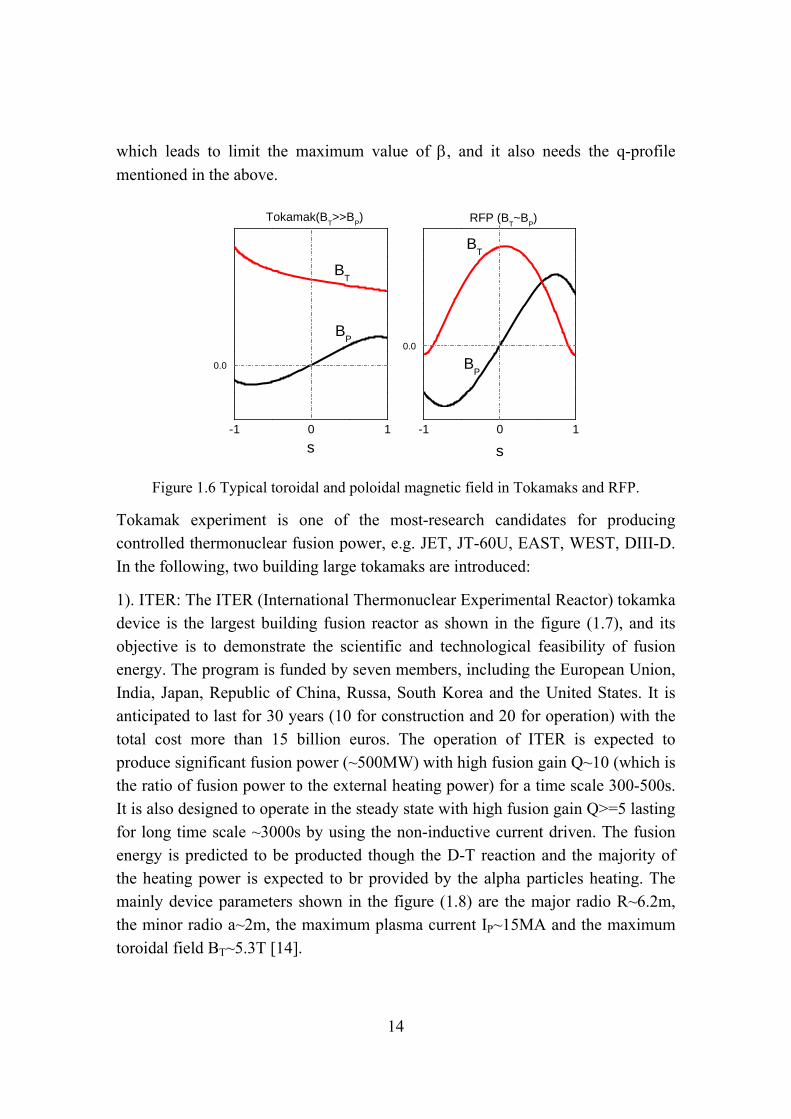
14
which leads to limit the maximum value of , and it also needs the q-profile
mentioned in the above.
-1 0 1
BP
s
0.0
BT
Tokamak(BT>>B
P)
-1 0 1
BP
BT
RFP (BT~B
P)
s
0.0
Figure 1.6 Typical toroidal and poloidal magnetic field in Tokamaks and RFP.
Tokamak experiment is one of the most-research candidates for producing controlled thermonuclear fusion power, e.g. JET, JT-60U, EAST, WEST, DIII-D. In the following, two building large tokamaks are introduced:
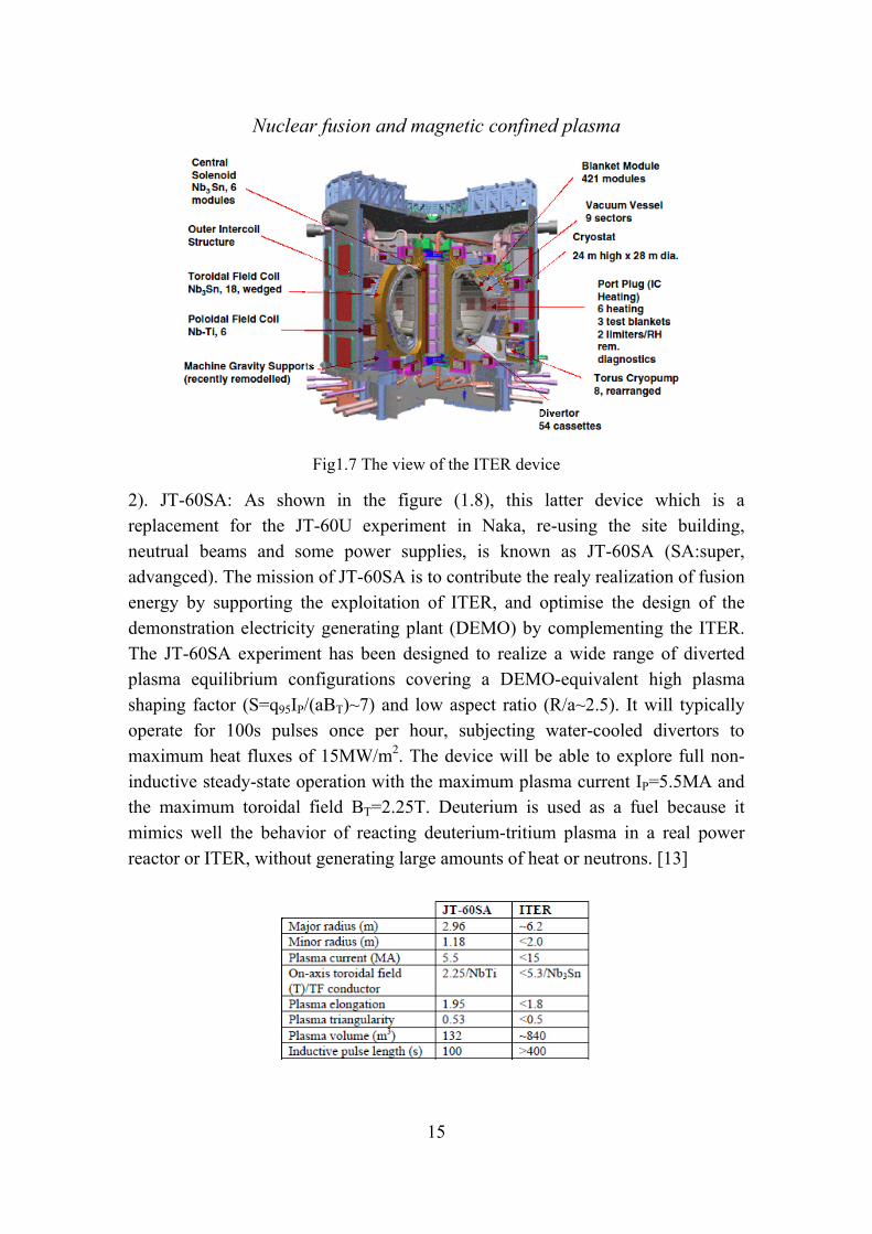
1). ITER: The ITER (International Thermonuclear Experimental Reactor) tokamka device is the largest building fusion reactor as shown in the figure (1.7), and its objective is to demonstrate the scientific and technological feasibility of fusion energy. The program is funded by seven members, including the European Union, India, Japan, Republic of China, Russa, South Korea and the United States. It is anticipated to last for 30 years (10 for construction and 20 for operation) with the total cost more than 15 billion euros. The operation of ITER is expected to produce significant fusion power (~500MW) with high fusion gain Q~10 (which is the ratio of fusion power to the external heating power) for a time scale 300-500s. It is also designed to operate in the steady state with high fusion gain Q>=5 lasting for long time scale ~3000s by using the non-inductive current driven. The fusion energy is predicted to be producted though the D-T reaction and the majority of the heating power is expected to br provided by the alpha particles heating. The mainly device parameters shown in the figure (1.8) are the major radio R~6.2m, the minor radio a~2m, the maximum plasma current IP~15MA and the maximum toroidal field BT~5.3T [14].
Nuclear fusion and magnetic confined plasma
15
Fig1.7 The view of the ITER device
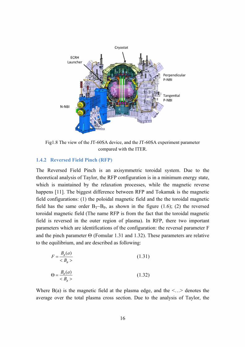
2). JT-60SA: As shown in the figure (1.8), this latter device which is a replacement for the JT-60U experiment in Naka, re-using the site building, neutrual beams and some power supplies, is known as JT-60SA (SA:super, advangced). The mission of JT-60SA is to contribute the realy realization of fusion energy by supporting the exploitation of ITER, and optimise the design of the demonstration electricity generating plant (DEMO) by complementing the ITER. The JT-60SA experiment has been designed to realize a wide range of diverted plasma equilibrium configurations covering a DEMO-equivalent high plasma shaping factor (S=q95IP/(aBT)~7) and low aspect ratio (R/a~2.5). It will typically operate for 100s pulses once per hour, subjecting water-cooled divertors to maximum heat fluxes of 15MW/m2. The device will be able to explore full non-inductive steady-state operation with the maximum plasma current IP=5.5MA and the maximum toroidal field BT=2.25T. Deuterium is used as a fuel because it mimics well the behavior of reacting deuterium-tritium plasma in a real power reactor or ITER, without generating large amounts of heat or neutrons. [13]
16
Fig1.8 The view of the JT-60SA device, and the JT-60SA experiment parameter
compared with the ITER.
1.4.2 Reversed Field Pinch (RFP)
The Reversed Field Pinch is an axisymmetric toroidal system. Due to the theoretical analysis of Taylor, the RFP configuration is in a minimum energy state, which is maintained by the relaxation processes, while the magnetic reverse happens [11]. The biggest difference between RFP and Tokamak is the magnetic field configurations: (1) the poloidal magnetic field and the the toroidal magnetic field has the same order BT~BP, as shown in the figure (1.6); (2) the reversed toroidal magnetic field (The name RFP is from the fact that the toroidal magnetic field is reversed in the outer region of plasma). In RFP, there two important parameters which are identifications of the configuration: the reversal parameter F
and the pinch parameter (Fomular 1.31 and 1.32). These parameters are relative
to the equilibrium, and are described as following:
( )B aF
B
(1.31)
( )B a
B
(1.32)
Where B(a) is the magnetic field at the plasma edge, and the <…> denotes the average over the total plasma cross section. Due to the analysis of Taylor, the

Nuclear fusion and magnetic confined plasma
17
prediction shows that the field reversal occurs at =1.2. The RFP plasma is with
the parameters >1.2 and F<0, which is relatively high- configuration compared
to the Tokamaks (low- and F>0). The RFP plasma is working with low-q
compared with tokamak, and it allows many MHD modes. The MHD instabilities can be stable by the presence of a conducting close-fitting wall, because of the very strong stable effects on the MHD instabilities due to special relaxation mechanism in the RFP devices. Furthermore, the active feedback controlling system is another passively way and gives an excellent improvement in the RFP development.
The RFX-mod, as shown in the figure (1.9), is a large RFP experiment device, with a/R=0.459(m)/2.00(m), maximum applied toroidal field BT=0.7(T) and plasma current IP<=2(MA). The modification based on the original device (RFX) is aiming at improving plasma boundary: the plasma is surrounded by a thin copper shell instead of the thick shell, covered by the 48 toroidal × 4 poloidal (192) external shadow coils with independent pow supplies; the redial field sensor loops of the same size are located inside the shell; the effective penetration time is
b~100ms. Compared with the initial passive shell operation, the modification
allows controlling the MHD instabilities selectively and effectively [12].
Figure 1.9 The view of RFP-mod experiment.

18
1.5 ResistiveWallModeinTokamaksandinRFPs
As described in the above sections, the Resistive Wall Mode (RWM) is the special from of the external ideal kink mode. The ideal kink instability can be completely stabilized by surrounding an ideal conducting wall that is closed enough to the
plasma. It becomes a slowly growthing instability (the order ~ 1/ w ) by
surrounding the finite conducting wall in reality. Where the w is the wall time,
and it is much larger compared to the Alfven time ( w A ). This RWM sets a
beta limit in the advanced tokamak scenarios, which is expected to run in the high beta value and a steady state. For RFP, the RWM can be unstable even without the
plasma pressure (=0), due to the very large toroidal current compared to the
toroidal magnetic field. Thus the RWM in RFP plasma which may cause the disruption needs be suppressed during the discharge lifetime.
In order to understand physics of the RWMs, the perturbations are described in the cylindrical coordination, with the poloidal wave number m and the the toroidal wave number n:
A r,θ,z,t =A r exp[-iωt+i(mθ+ z)]n
R (1.33)
Where r i is the mode eigenvalue, including the mode frequency r and
the mode growth rate . By specifying the wave number m and n, the RWM is
also called (m, n) mode, and its resonance surface is located where the safety
factor is equal to m/n ( ( ) /q r m n ). In particular, the characteristic of RWM in
both RFP and tokamaks is described as following:
0.006 0.007 0.008 0.009 0.010 0.011 0.012 0.013
10-6
10-5
10-4
10-3
10-2
10-1
=0.0078
RWM
kink ideal-wall
kink no-wall
/A
n=-1,b/a=1.12
=0.0118

Nuclear fusion and magnetic confined plasma
19
Figure 1.10 The growth rate of RWM and kink mode versus total plasma , including the
no-wall limit and the ideal-wall limit of tokamak.
1). In tokamaks, the RWM usually has the wave number n=1. With no wall ( 0w )
outside the plasma, the external kink is unstable if > no-wall, where no-wall is
called no wall limit. With an ideal wall ( w ) outside the plasma, the external
kink is unstable if > ideal-wall, where ideal-wall is called ideal wall limit. The
RWM is the mode with a conducting wall in the region no-wall<<ideal-wall. The driven source is dominated by the pressure driven, due to the very large toroidal
field BT. In the figure (1.10), it shows the no-wall limit, the ideal-wall limit and the
growth rate of RWM by increasing the plasma pressure.
Figure 1.11 The q-profile of tokamak, including the resonance (2, 1) and (3, 1) modes and
the non-resonance (4, 1) and (5, 1) modes.
Figure (1.11) shows the q-profile and the resonance positions in the radial direction. The RWMs with their resonance surface inside the plasma are called resonance mode, such as (2, 1) and (3, 1) modes; on the other hands, the RWM are called non-resonance modes, such as (4, 1) and (5, 1) modes. Due to the strong toroidal effect in tokamak, many poloidal coupling harmonics grows.
2). In RFPs, the dominated mode is usually m=1 and the other modes are much smaller due to the very weaker toroidal effect, for each mode with different toroidal wave number n. Due to the very large toroidal current, the RWM can not be stable, where the main driven source is the current driven. As shown in figure
(1.12), the no-wall limit is equal to zero, which means that the RWMs is

20
unstable even at zero pressure. The ideal wall beta limit still exists, where the plasma pressure is high sufficiently.
0.00 0.05 0.10 0.15 0.20 0.2510-4
10-3
10-2
10-1
100
F=-0.06,q0=0.1448,b=1.12
n=6,P-limit=0.16
RWM ideal-wall kink
/A
P
Figure 1.12 The growth rate of RWM and kink mode versus poloidal plasma P,
including the no-wall limit (=0) and the ideal-wall limit of tokamak.
In RFPs as shown in the figure (1.13), there are two types of external kink instabilities: one is so called externally non-resonant modes (ENRM) with their rational surfaces located at q < q(a) <0, another is internally non-resonant modes (INRM) with their rational surfaces located at q > q(0) > 0. (q(a) is the value of safety factor at the plasma edge, and the q(0) is the value of safety factor at the plasma center)
Figure 1.13 The q-profile of tokamak, with externally non-resonant modes such as (-1, 6) and (-1, 5) modes, and internally non-resonant modes such as (1, 5) and (1, 6) modes. [36]
Nuclear fusion and magnetic confined plasma
21
1.6 Fish‐boneLikeModeinTokamaksandinRFPs
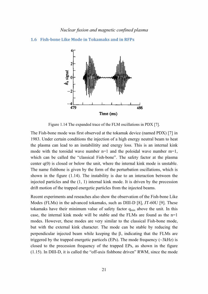
Figure 1.14 The expanded trace of the FLM oscillations in PDX [7].
The Fish-bone mode was first observed at the tokamak device (named PDX) [7] in 1983. Under certain conditions the injection of a high energy neutral beam to heat the plasma can lead to an instabilitity and energy loss. This is an internal kink mode with the toroidal wave number n=1 and the poloidal wave number m=1, which can be called the “classical Fish-bone”. The safety factor at the plasma center q(0) is closed or below the unit, where the internal kink mode is unstable. The name fishbone is given by the form of the perturbation oscillations, which is shown in the figure (1.14). The instability is due to an interaction between the injected particles and the (1, 1) internal kink mode. It is driven by the precession drift motion of the trapped energetic particles from the injected beams.
Recent experiments and reseaches also show the observation of the Fish-bone Like Modes (FLMs) in the advanced tokamaks, such as DIII-D [8], JT-60U [9]. These tokamaks have their minimum value of safety factor qmin above the unit. In this case, the internal kink mode will be stable and the FLMs are found as the n=1 modes. However, these modes are very similar to the classical Fish-bone mode, but with the external kink character. The mode can be stable by reducing the
perpendicular injected beam while keeping the , indicating that the FLMs are triggered by the trapped energetic particels (EPs). The mode frequency (~3kHz) is closed to the precession frequency of the trapped EPs, as shown in the figure (1.15). In DIII-D, it is called the “off-axis fishbone driven” RWM, since the mode

22
frequency is chirping. In JT-60U, it is called energetic particle-driven wall mode
(EWM). This is emphasizing their observation in the wall-stabilized high- plasma.
It means that the FLMs is destabilized in the region no-wall<<ideal-wall, in which
the external kink (reduced to the RWMs instabilities in general) can be stabilized by the ideal conducting wall and the internal kink (1, 1) mode is always stable.
Figure 1.15 The observations of the FLMs in JT-60U [9] and DIII-D [8].
The EPs driven instability has also been found in MST (RFP device) [10]. The instability is a resonance mode with the toroidal wave number n=4 (non-resonance mode) and n=5 (resonance mode), the safety factor at the plasma center is 0.25>q(0)>0.2. It is called energetic particle mode (EPM). The mode frequency (~90kHz) is very high compared to the FLMs in the tokamaks, as shown in the figure (1.16). However, many behaviors of these observed EPMs have not been understood clearly, due to the very few NBI experiments in RFPs. Thus the physical study is very useful to predict the behaviors of the EPs in the RFP plasma.
The studies in this thesis are much relevant to the experimental observation such as in JT-60U, DIII-D and MST et al.

Nuclear fusion and magnetic confined plasma
23
Figure 1.16 A single n=5 burst from the Mirnov coils and apectrogram n=5
interferometry measurments at R-R0=-0.02.


Theoretical Models and Formulations
25
Equation Chapter (Next) Section 1
Chapter 2
2 TheoreticalModelsandFormulations
2.1 TheoreticalModels
The MARS-K code numerically solves the linearized, single-fluid MHD equations with self-consistent inclusion of drift kinetic resonances in toroidal geometry [39].
For a given curvilinear flux coordinate system , ,s , and by assuming that all
the perturbations have the form , , , , i t inA s t A s e . The MHD equations,
including the kinetic terms, are written in the Eulerian frame in the code as following:
2i n R ξ v ξ (2.1)
22 ˆi n R v p Q B B Q Z v v (2.2)
2i n R Q v B Q (2.3)
||ˆ ˆ ˆ ˆ( )p p p bb I bb (2.4)
Where s is the normalized radial coordinate, labeling the equilibrium flux surface,
is a generalized poloidal angle. r i is the complex eigenvalue of the
mode ( is the mode growth rate, r is the mode rotation frequency in the
laboratory frame). The mode frequency is corrected by a Doppler shift in , with n being the toroidal mode number, is the plasma rotation frequency in the torodial
direction. , , v, Q, p represent the perturbed quantities: the plasma displacement,
the perturbed velocity, magnetic field, and pressure tensor, respectively. is the
unperturbed plasma density. R is the plasma major radius. Z is the unit vector in the vertical direction. B and P denote the equilibrium magnetic field and pressure, respectively. A conventional unit system is assumed with the vacuum permeability
0 =1. For the RWM study, a set of vacuum equations for the perturbed magnetic
Theoretical Models and Formulations
26
field Q , and the resistive wall equation based on the thin-shell approximation, are
solved together with Eqs. (2.1)-(2.3) [62,40].
The drift kinetic effects from each particle species, including thermal ions and electrons as well as energetic ions, are self-consistently coupled to the MHD equations via the perturbed kinetic pressure tensor p, as shown in Eq.(2.4). I is the
unit tensor, and ˆ / | |b B B . The pressure tensor includes both parallel (to the
equilibrium magnetic field) ||p , and perpendicular p components. Each
components involoves both adiabatic (subscript “a”) and non-adiabatic (subscript
“na”) parts: || || ||a nap p p and a nap p p . These components are computed by,
00( )||a
g g
Q fp f E d
B
(2.5)
1nag L gp f E d (2.6)
Where 2g || ||E Mv , and 2
gE Mv B . The intergral is carried out over the
particles velocity space . M is the particle mass, and ||v and v are the parallel
and perpendicular components of the particle velocities repectively. The perturbed
particle distribution function 1Lf is derived from solution of the perturbed drift
kinetic equtions, following the approaches by Antonsen [64] and Procelli [65], and written by,
1 0 bin t im il ti t inL k m ml ml
m,l
f f e X H e (2.7)
0f is the energy derivative of particle equilibrium distribution function 0f .
k Ze is the kinetic energy of the particle, where is the particle total
energy and Ze is the electrostatic potential with the charge number Ze. ( )t
denotes the periodic part of the particle motion along the toroidal direction, l is
harmonic number in the bounce orbit expansion. mX and mlH are related to the
perturbed particle Largrangian [39].
Nuclear Fusion and Magnetic Confined Plasma
27
For thermal ions and electrons, the particle equilibrium distribution function is assumed by Maxwellian distribution. The key element in the formulation (Eq.(2.7)) is the wave-particle resonance operator, which is expressed as,
* *ˆ 3 / 2N k Tml
d b eff
n
n m nq l n i
(2.8)
where *N and *T are the diamagnetic drift frequencies due to the plasma density
and temperature gradients, respectively. In this drift kinetic formulation, it has been assumed that the effect of finite radial excursion width of particles across
magnetic surfaces is negligible. q is the safety factor. eff is the effective collision
frequency. /k k T is the particle kinetic energy normalized by the temperature.
d is the bounce-orbit-averaged precession drift frequency. For trapped particles,
0 , and b is the bounce frequency. For passing particles, 1 , and b
represents the transit frequency. In further discussions we also use a notation p
for the transit frequency, in order to distinguish from the bounce frequency. Equation (2.8) includes particle bounce, transit, as well as magnetic precession drift resonances with the mode. The imaginary part of the resonant operator represents damping physics resulted from the energy transfer between the mode and particles.
For EPs, the equilibrium distribution function has an overall slowing-down distribution in the particle energy space (isotropic distribution), and it is combined with a Gaussian model for the particle pitch angle distribution (anisotropic distribution). This expression is largely suitable for modelling the NBI driven EPs (isotropic/anisotropic) or alpha particles (isotropic distribution), which is written by [62,63],
013 2 3 2
1
2k k
ck
C( )f ( , , ) G ( , , )
(2.9)
2 21 k i i
iG ( , , ) C exp ( ) / (2.9.1)
Theoretical Models and Formulations
28
3 2 3 2
2 20 3 2 3 2
11
3
/ /k k
k / /k c
/, ln
(2.9.2)
Where || /v v is the pitch angle, and c corresponds to the crossover velocity of
EPs. 2 in Eq.(2.9.2) is the width of Gauss function, and is the birth energy of
the EPs. 20 is a constant tunable parameter, and the model denotes the isotropic
distribution if 0 . The distribution function can be defined by specifying a set
of the parameters { i iC , }.
For normal injected NBI, We have 0 5 0 5 0 5 0 5iC . , . , . , . and
0 0 0 02 2i , , , ;
For co-tangential injected NBI,
a). When 1s , 1 1 0 5 0 5iC , , . , . and
0 0 0 02 2 2 2i s s, , , ;
b). When s s , 0 5 0 5 0 5 0 5iC . , . , . , . and 0 0 0 02 2i , , , ;
c). When 1 s , 0 5 0 5iC . , . and 0 02 2 2i s s, .
Where s s are the trapped-passing boundaries in the pitch angle of EPs. 0
is another tunable parameter. Similar to the thermal particles, the resonance oparetor of EPs is expressed as Eq.(2.10).
0 0
EPd eff
f fn( / Ze )
n n i
(2.10)
Where d is the bounce-orbit-averaged precession frequency of the trapped EPs.
In this work, only precession drift of the trapped EPs is considered in the oparetor. Because the bounce and transit frequency of EPs are much larger than that of thermal particles and the precession frequency of EPs, the resonance between the
Nuclear Fusion and Magnetic Confined Plasma
29
mode and particles is difficult to occur. Thus these kinetic effects are neglected in the model.
The Maxwellian distribution of thermal particles and the isotropic slowing-down distribution of EPs are independent of the particle pitch angle, and the second term in the right hand side of Eq.(2.5) is vanished. This term is reserved only if the anisotropic slowing-down distribution of EPs is considered.
2.2 Quadraticenergyterms
In order to gain better physical understanding, we compute various components of the quadratic energy form, for both fluid and drift kinetic energy perturbations, from the self-consistent solution. As well known, the quadratic energy form can be
constructed by multiplying Eq. (2.2) by *ξ and integrating over the plasma volume
PV . We define the following energy components of the fluid potential energy FW
[6] and the kinetic potential energy kW
F j Q PW W W W (2.11)
21
2jW Q Jdsd d (2.11.1)
1( )
2||
Q ||
QW J P Jdsd d
B
b Q (2.11.2)
1( )
2a *
PW Jdsd d p (2.11.3)
where J is the Jacobian of the flux coordinates. We consider cases with vanishing perturbed surface current, where the surface terms in the potential energy disappear. In the energy calculation, we neglect the centrifugal and the Coriolis
force terms in the RHS of Eq.(2.2), assuming a slow equilibrium flow. ap is the
adiabatic part of the pressure tensor. The energy PW in Eq.(2.11.3) is summation
of energy from all the particle species, including the thermal ions, the thermal electrons and energetic ions in this work. The kinetic energy term is obtained by,
1 1 1( )
2 2 P
na * * na * na *K || || sS
W p Q B p Jdsd d p J d dB
ξ κ ξ ξ n (2.12)

Theoretical Models and Formulations
30
Where the surface intergral term in the right side of Eq.(2.12) is negligible if we assume that the equilibrium pressure vanishes at the plasma edge P (a)=0 (the perturbed kinetic pressure is roughly proportional to the equilibrium pressure).
Here pS is the plasma surface, sJ s J is the surface Jacobian, n is the outward
normal vector to the vacuum region.
We also compute the vacuum energy vW and vbW , without wall and with an
ideal wall at the minor radius b, respectively
2
1 1
1 1 ˆ2 2 p
nv sS
V
W Jdsd d b V J d d
Q (2.13)
2
1 1
1 1 ˆ2 2 p
b
n bvb sS
V
W Jdsd d b V J d d Q (2.14)
where 1nb is the normal magnetic field perturbation, and related to the perturbed
magnetic components Q1 with 11n
sQ J b [42]; The component Q1 is essentially the
perturbed flux function. 1V and 1bV are the complex conjugates of the perturbed
magnetic scalar potential, which are determined by the ideal wall position and 1nb
at the plasma surface [6]. The two vacuum energy terms are associated with the vacuum magnetic field perturbation, induced by the plasma instability. They are
always positive and play a stabilizing role for the RWM. vW and vbW can be
written either in a volume integral, or in a surface integral as shown in Eqs. (2.13) and (2.14).
Equations (2.11)-(2.14) are implemented in the MARS-K code [26, 27], and applied for the energy analysis of the RWM physics in the present work.
2.3 Equilibriumprofilesofthepressureandthedensity
In this section, the equilibrium profiles, which are used in the following chapers, are described. We chose the density profile model of the electrons as,
20 1e en s n s ( e in n n ) (2.15)

Nuclear Fusion and Magnetic Confined Plasma
31
Where en , in , n denote the density of thermal electrons, thermal ions and
energetic particles respectively. We have e in n if the energetic particles are not
considered. The electron density at the plasma core is 19 30 2 5 10en . / m .
For RFP plasma, the total plasma pressure by seting the parameters ap1, ap2, ap3 is described as,
2 4 60 1 2 31eq p p pP s P a s a s a s (2.16)
For Tokamak plasma, the total plasma pressure is given by,
220 1eqP s P s (2.17)
Where the 0P is the total plasma pressure at the magnetic axis. If the energetic
particles are not taken into account, we have eq i eP P P .
By considering the energetic particles (which are energetic ions from the NBI injection in the thesis), the slowing-down distribution function combined with a Gaussian model (as a function of the pitch angle) is used to describe the isotropic/
anisotropic EIs. The birth energy in this work is chosen constant along the
minor radius. Besides, the pressure of the EPs is described by the fraction profile of the pressure Pa/Pth (where Pth and Pa are the pressure of the thermal particles and EPs, the total plasma pressure is Ptotal= Pa + Pth). Similarly, the density of the EPs is described by the fraction profile of the density Na/Ne (where Na and Ne are the density of the EPs and electrons, the electron density is Ne= Na + Ni).
For RFPs, we define the ratio * thP P/ , where P
and thP are the poloidal beta
of the thermal particles and EPs respectively. For Tokamaks, we define the beta
ratio * th/ , where and th are the total plasma beta of the thermal
particles and EPs respectively. We also define 0* to denote the pressure fraction
Pa/Pth at the magnetic axis. In the RFP plasma as an example, the equilibrium (a)
pressure (normalized by the 20 0B / ) and (b) density profiles (normalized by the
Ne(0) at the magnetic axis) are plotted in the figure.(2.1) and figure.(2.2), for the thermal ions and electrons as well as the energetic ions respectively. The

Theoretical Models and Formulations
32
* thP P/ is equal to the pressure fraction Pa/Pth = 0
* if we take Pa/Pth=constant
along the minor radius, for example, 0 0 3* . and 0 3* . as shown in the
figure.(2.1). If the pressure of the EIs is given by the pressure fraction
2 80(1 )*
a thP / P s s , as the example shown in the figure.(2.2) we have 0 1 0* .
and 0 176* . .
0.0 0.2 0.4 0.6 0.8 1.00.00
0.01
0.02
0.03
0.04
0.05
0.06
0.07
P_total=0.155,*=0.3,
=100keV
Ptotal
Pthermal
Phot
0P/B
0
2
s
(a)
0.0 0.2 0.4 0.6 0.8 1.00.0
0.1
0.2
0.3
0.4
0.5
0.6
0.7
0.8
0.9
1.0
(b)
Ne(=Na+Ni) Ni Na
P_total=0.155,*=0.3,
=100keV
N/N
e(s
=0)
s
Figure 2.1 The equilibrium (a) pressure (normalized by the 20 0B / ) and (b)
density profiles (normalized by the Ne(0) at the magnetic axis) are plotted for the thermal ions and electrons as well as the energetic ions respectively. The
equilibrium parameters are 0 3a thP / P s . , 0 155P . and 100keV . The beta
ratio is 0 0 3* . ( 0 3* . ).
0.0 0.2 0.4 0.6 0.8 1.00.00
0.01
0.02
0.03
0.04
0.05
0.06
0.07
Pre
ssur
e (n
orm
ailz
ed b
y B
02 /0)
s
Ptotal
Pthermal
Pa
Pa/Pth(s)=(1-s2)8
P=0.14
a=100keV
(a)
0.0 0.2 0.4 0.6 0.8 1.00.0
0.2
0.4
0.6
0.8
1.0
Ne(=Na+Ni) Ni Na
Pa/Pth(s)=(1-s2)8
P=0.14,
a=100keV
Den
sity
(no
rmal
ized
by
the
Ne(
0))
s
(b)
Figure 2.2. The equilibrium (a) pressure (normalized by the 20 0B / ) and (b)
density profiles (normalized by the Ne(0) at the magnetic axis) are plotted for the

Nuclear Fusion and Magnetic Confined Plasma
33
thermal ions and electrons as well as the energetic ions respectively. The
equilibrium parameters are 2 8(1 )a thP / P s s , 0 14P . and 100keV . The
beta ratio is 0 1 0* . ( 0 176* . ).

Shaping effect on MHD stabilities in reversed field pinch (RFP) plasmas
35
Equation Chapter (Next) Section 1
Chapter 3
3 ShapingeffectonMHDstabilitiesinreversedfieldpinch(RFP)plasmasThe optimization of the geometrical shape for the toroidal fusion plasmas is an important issue. For example, it is well known that for an advanced tokamak design, the appropriate D-shape cross-section can result in a higher performance
towards high steady state fusion plasmas. In Tokamaks, shaping often helps to
increase the favourable curvature region which is inherently stabilising for a few MHD modes. In addition, elongation normally helps to increase the total plasma
current I, by a factor (1+2)/2, with the same q(a) value, where is the elongation
factor and q(a) the plasma edge safety factor. A larger current normally yields a
better confinement. Furthermore, since the no-wall beta limit N [N=T(aBT/I) ,
T = 2μ0<p>/BT2, <p> is the average plasma pressure, μ0 the vacuum permeability
and BT the strength of the toroidal magnetic field] for the ideal kink instability in Tokamak is related to the total current[17-19], increasing current implies the
possibility to maximize the value for an advanced Tokamak, without changing
other parameters such as N, a, and BT. The value of N is often determined by
the radial profiles of equilibrium quantities such as the plasma pressure and current, and can be largely independently controlled from the total plasma current.
As an alternative fusion experimental device, Reversed Field Pinch (RFP) has toroidal axisymmetry as well [20]. Nevertheless, all of the existing RFPs possess circular cross section. There is no experimental evidence showing whether shaped plasma in RFP can bring an advantage for its performance. Recently, significant progress has been made in RFP studies both in experiments and theory [21,22]. The question of how to improve the RFP design towards an advanced fusion device is placed on the agenda. The macroscopic MHD instabilities in RFP plasmas are often categorized into resonant and non-resonant modes, depending on

Shaping effect on MHD stabilities in reversed field pinch (RFP) plasmas
36
whether the mode's rational surface is located inside (resonant) or outside (non-resonant) the plasma. It is also conventional to divide the instabilities into internal and external modes, depending on whether the mode is located inside or outside the toroidal field reversal radius. The plasma shaping effect has previously been studied in early work [23], with the main conclusion that the plasma shaping does not have a significant effect on the stability of the resonant ideal modes and the interchange modes, either with or without a finite plasma pressure. The study assumed an ideal wall surrounding the plasma. On the other hand, the resonant ideal kink modes have been experimentally observed being stable in RFP plasmas due to the self-organized relaxation process. It is now understood that the most important (and/or commonly observed) instabilities in RFP plasmas are the (internal and external) non-resonant ideal modes (the resistive wall modes) and the resonant resistive modes (the tearing modes) [24,25]. The later is responsible for the necessary dynamo effect to maintain the RFP magnetic configuration. The pressure driven interchange mode can be unstable when the Mercier criterion is violated, which is a rather localized mode due to the high magnetic shear in the
RFP configuration. It may not be the most dangerous mode to set the limit for
RFP plasmas. In the present work we systematically investigate the shaping effects on the most prominent MHD instabilities - the Resistive Wall Mode (RWM) and the Tearing Mode (TM) - observed in RFPs, with the aim to find out whether the shaping can bring an advantage for improving the performance of RFPs. Moreover, the present work includes the following key aspects: (i) an in-depth physics understanding of the shaping effects based on the detailed energy analysis of the modes; (ii) the drift kinetic effects on the resistive wall modes in the presence of shaping, following a non-perturbative approach; (iii) the shaping induced multiple trapping and modification of bootstrap fraction. Both the plasma elongation and the triangularity are taken into account. The kinetic- MHD hybrid toroidal stability code MARS-K has been modified and adopted for the RFP study [26,27].
We first consider the stabilities of the non-resonant ideal kink mode and related RWM, which are commonly observed in RFPs [28,11,30,31,32,33,34,35,36,6], in
shaped plasmas. Both fluid theory and the kinetic effects of the high thermal
particles are considered. The RFP magnetic configuration is characterized by the reversed toroidal magnetic field BT near the edge and a large poloidal field Bp which has the strength of the same order as the toroidal field. Compared with the

Shaping effect on MHD stabilities in reversed field pinch (RFP) plasmas
37
tokamak configuration with the same BT at the magnetic axis, RFP has much higher plasma current, which in turn can provide sufficiently large ohmic heating, allowing the possibility of reaching the fusion reaction [20, 6]. However, a large current often causes the current driven RWM (basically an ideal kink mode instability), which can be unstable even at vanishing plasma pressure, thus leading
to a zero no-wall limit (Nno-wall=0). Furthermore, the strong poloidal magnetic
field Bp gives a dominant contribution to the magnetic curvature, implying that bad magnetic curvatures exist everywhere along the poloidal angle. The plasma shaping does not change this fundamental feature. On the other hand, shaping does cause a significant variation of the field strength along the poloidal angle, resulting in an enhancement of the poloidal mode coupling and an occurrence of multiple trapping regions as we shall show. Consequently, the shaping effect on the RFP plasmas is generally quite different from that on tokamak plasmas.
In this work, we find that the ideal wall limit (i.e. the ideal kink stability
threshold) is reduced by shaping for both internally and externally non-resonant modes. The kinetic effects of thermal particles become more significant in the
shaped RFP, stabilizing the RWM at relatively lower values than that in a
circular RFP. However, the required plasma rotation frequency for the mode suppression is still in the ion acoustic range as being found in circular RFPs [26]. We report detailed physics understanding on the mechanisms underlying these results.
Next, we study the linear stability of the resistive tearing modes, which are responsible for the dynamo effects in RFPs, in shaped plasma and compare the results with that of the circular cases. Finally the effect of shaping on the bootstrap currents of RFP plasmas is also preliminarily studied and discussed. We observe that the shaping effects with respect to all these aspects do not result in a notable change of the RFP performance.
The paper is organized as follows. Section 3.1 discusses the shaping model and the
quadratic energy terms. Section 3.2 investigates the limit set by the ideal kink
and the RWM in shaped plasmas. In Sec. 3.3, kinetic damping on the RWM in shaped RFP is studied. In Sec.3.4, the results of shaping effects on the resistive
tearing mode instability in low RFP plasmas are presented. Section 3.5 discusses

Shaping effect on MHD stabilities in reversed field pinch (RFP) plasmas
38
the bootstrap current fraction in both circular and shaped RFP plasmas. The conclusion and a brief discussion are given in Sec. 3.6.
3.1 ModelsandFormulations
3.1.1 Elliptic,triangularandDshapedRFPplasmas
The shape of the plasma boundary is described by the following formulae:
R R R cos( sin( ))0 0 (3.1)
Z R sin( ) 0 (3.2)
where R and Z are the Cartesian coordinates with the origin at the center of the
torus, R0 is the major radius, is the inverse aspect ratio, is the elongation and
is the triangularity. The RFP equilibria are computed by solving the Grad-Shafranov equation using the CHEASE code [38], given the plasma current and pressure profiles as the input, together with the plasma boundary specified above. Figure 3.1 shows examples of the computed equilibrium flux surfaces with various
shaped cross sections: circular (=1.0, =0.0), elliptic (=1.3, =0.0), triangular
(=1.0, =0.3) and a D-shape (=1.3 and =0.3). In order to make sensible comparisons between different shaping parameters on the RFP physics, we keep the areas of the cross sections invariant for different types of shaping, meaning that all types of the cross-sections have the same area as that of the circular case,
a2. In addition, the following parameters have the same values for various shapes
in the computation: the safety factor at the magnetic axis q(0), the field reversal parameter F and total plasma current I. Here F is define as F=BT(a)/<BT>, where <…> is the average over the plasma volume.

Shaping effect on MHD stabilities in reversed field pinch (RFP) plasmas
39
Fig.3.1. The plots of the shaped poloidal magnetic flux surfaces of RFP equilibria
for F= -0.06 q=0.1448 and P=0.12: (a) circular RFP with aspect ratio
=a/R=0.2295, elongation =1.0 and triangularity =0.0; (b) elliptic, =1.3 and
=0.0, and =0.2012; (c) triangular, =1.0 and =0.3, =0.2308; (d) D-shape,
=1.3 and =0.3, =0.2024,. All types of the cross sections have the same area as
the area in (a).
3.1.2 Quadraticenergyterms
In order to gain better physical understanding, we compute various components of the quadratic energy form, for both fluid and drift kinetic energy perturbations, from the self-consistent solution. As well known, the quadratic energy form can be
constructed by multiplying Eq. (2.2) by *ξ and integrating over the plasma volume
PV . We define the following energy components of the fluid potential energy WF
[6,41] and the kinetic potential energy Wk
F mb mc pre curW W W W W (3.3)
21
2 P
mb
V
W Jdsd d Q (3.3.1)
2212
2 P
mc
V
W B Jdsd d ξ ξ κ (3.3.2)
*1
2 P
pre
V
W P Jdsd d ξ κ ξ (3.3.3)
*/ /
1
2 P
cur
V
W J Jdsd d ξ b Q (3.3.4)

Shaping effect on MHD stabilities in reversed field pinch (RFP) plasmas
40
where J is the Jacobian of the flux coordinates. mbW is the magnetic bending term
representing the energy required to bend magnetic field lines, mcW responds to the
energy necessary to compress the magnetic field. Both terms are positive and give
stabilizing contributions. preW and curW represent potential sources of instability,
and are referred to as the pressure driven and the current driven terms, respectively.
Both preW and curW can be negative. We consider cases with vanishing
perturbed surface current, where the surface terms in the potential energy disappear. In the energy calculation, we neglect the centrifugal and the Coriolis force terms in the RHS of Eq. (2.2), assuming a slow equilibrium flow. The kinetic energy term is then obtained
3.2 RFPequilibrium
3.2.1 InstabilityspectrumoftheRWMinRFPs
With respect to tokamaks, the RFP plasmas are easier to be “kinking” due to the weaker toroidal field in the configuration. As a result, the RWM, being a potentially disruptive instability, grows whenever the duration of the discharge is longer than the wall penetration time, even in the absence of the plasma pressure.
Furthermore, due to the toroidal field reversal, resulted from the relaxation process, RFPs can operate in a stable regime of the “resonant” (with rational surface being inside the plasma) ideal kink modes. The observed RWM instabilities always have their rational surfaces outside the plasma. They are the so-called “externally non-resonant” modes (ENRM), if the rational surfaces are located at q < q(a) <0 (q(a) is the safety factor at the plasma edge r=a), or the “internally non-resonant” modes (INRM), if the rational surfaces are located at q > q(0) > 0 [28,35,36]. In the following, we use n<0 to denote the INRM; and n>0 to represent the ENRMs. The experimentally observed resonant modes (with the resonant surface inside the plasma) are tearing modes, which are generally believed to be responsible for the dynamo generation in RFPs. We use n<0 to denote the tearing mode with the rational surface inside the BT reversal position, and vice versa.
Shown in Fig.3.2 is the plot of the RWM growth rate as a function of the toloidal mode numbers n, where both internally and externally non-resonant modes are
computed by MARS-K in a circular, zero RFP plasma without plasma flow. The

Shaping effect on MHD stabilities in reversed field pinch (RFP) plasmas
41
wall position of b/a=1.12 and the inverse aspect ratio of =0.23 are taken from the
RFX-mod [43] parameters. The wall time is taken as w/A ≈6.4103 , where w is
the penetration time of the resistive wall and A is the Alfven time calculated at the
magnetic axis. As we already observed previously [36], a shallower reversal (a smaller negative F value) results in a larger growth rate of the INRM and a smaller growth of ENRM; and vice versa. The modes with n<-6 ( e.g. n=-7,-8…) are resonant modes, and are observed experimentally as tearing modes.
Fig.3.2. The mode growth rates versus the toroidal mode number n are plotted for different F(=-0.06, -0.1, -0.26, -0.4, -0.8, -0.9, -1.0) values. Two groups of RWMs,
INRMs(n<0) and EXRMs(n>0), are plotted. The fluid model with P=0.0,
q(0)=0.1448, 0=0.0, and b/a=1.12, =0.23 is used in circular RFP. The poloidal
Fourier harmonics from m=-10 to m=10 are taken into the calculation.
3.2.2 IdealWalllimitofRWM(idealkinkinstability)
In RFP plasmas, all RWMs are current driven modes, therefore the no-wall p
limit pno-wall=0 (
2
8p tot
o
p VI R
, <p> is the volume averaged plasma pressure,
2Vtot is the total plasma volume [38]); whilst the ideal wall p limit, pideal, is
finite for given wall position at the minor radius rb=b. When p> pideal , the non-
resonant ideal kink mode becomes unstable with the ideal wall at rb=b. For p <
pideal, the RWM instability appears if the ideal wall is replaced by a resistive wall.

Shaping effect on MHD stabilities in reversed field pinch (RFP) plasmas
42
When the plasma elongation and triangularity are introduced, it is found that the shaping induces a strong poloidal coupling, which increases the mode growth rate
and reduces the ideal-wall limit for both the INRM and the ENRM. Figure 3.3
shows the RWM eigenfunctions (the perturbed magnetic field in the normal direction) Qm
1of various poloidal harmonics for (a) a circular case (b) a case with
elongation only, =1.3 and =0.0, (c) a case with triangularity only, =1.0, =0.3.
It shows that in a circular toroidal RFP plasma [Fig.3.3(a)], the m=1 mode has a dominant amplitude, and the m=2, 3… modes appear with low amplitudes due to the weak coupling by toroidicity [27]. Note that RWMs in circular RFP plasmas have much weaker toroidal coupling than that in tokamaks due to the weaker poloidal asymmetry induced by the strong poloidal field. The elongation [Fig.3.3(b)] induces the variation of the magnetic field strength along the poloidal
angle, which in turn enhances the mode coupling between m=1 and m=±2. As a
result, the m=-1 and m=3 modes have much larger amplitudes with respect to the circular case. The triangularity [Fig.3.3(c)] induces the multiple coupling between
m=1 and m=±1,m=±2 and m=±3 modes, such that multiple modes appear due
to the coupling, but with less increments of the amplitudes compared to the elongation induced mode coupling.
Fig.3.3. The eigenfunctions of various poloidal harmonics Qm1 (real parts of the
perturbed magnetic component in the normal direction) for n=-6 RWM are plotted as a function of magnetic flux coordinate s for different shapes of RFP plasmas,

Shaping effect on MHD stabilities in reversed field pinch (RFP) plasmas
43
where m=-10 to 10 are taken into account. The mode amplitudes are normalized
by the maximum absolute value max (Qm=11). (a) circular, =1.0 and =0.0;
(b)elliptic, =1.3 and =0.0; (c) triangular, =1.0 and =0.3. Other parameters are
F=-0.06, q(0)=0.1448, P=0.0, b/a=1.12 and 0=0.0.
Figure 3.4 shows the RWM growth rate plotted as a function of the elongation with different values of triangularity. The normalized mode growth rate
(normalized by A) increases with , showing a destabilizing role played by
elongation. This destabilization is also consistent with the decrease of the ideal-wall beta limit as will be shown in Fig.3.5(a). The triangularity itself slightly
increases the RWM growth rate in the absence of elongation (=1). When the
triangularity is combined with elongation, it causes a slight cancellation of the destabilizing effect due to the elongation. The net effect still leads to an increase of the RWM growth rate.
Fig.3.4. The growth rates of the n=-6 RWMs versus elongation parameter are
plotted for various triangularities: =0.0 (solid line); =0.3 (dash line); =0.5
(dash-dot line), with the same parameters as shown in Fig.3.3
Figure 3.5 plots the computed ideal-wall p limits with varying wall position, for
different toroidal harmonics of the RWMs. The INRMs with n=-6, -5 and -4 are

Shaping effect on MHD stabilities in reversed field pinch (RFP) plasmas
44
plotted in (a), and the ENRMs with n=4, 3, 2 are plotted in (b). Each line indicates the stability boundary of the ideal kink mode. This boundary depends on both the
p value and the normalized wall position b/a. The unstable domains are located
above and to the right of the lines, and the (ideal mode) stable domains below and
to the left of the lines. For =1.3, the pideal values are largely reduced with respect
to the circular case. For the most unstable RWM observed in RFX-mod, with n=-6,
which set most severe pideal limit and the closest-fitting wall position among all
the RWMs, the circular plasma model gives pideal=0.16, the elongation reduces
this value to pideal=0.13 with the same wall position. Other toroidal harmonics
such as n=-5,-4 and n=4, 3, 2, have relatively smaller growth rates than that of n=-
6, thus setting higher p limits and moderately closer wall positions. The
triangularity =0.3 is also considered for the n=-6 mode in Fig.3.5(a) and for the
n=4 mode in (b) showing a similar, but less significant destabilizing effect than
the elongation. The results in Fig.3.5 indicate that, for a given plasma p, the
shaped RFP requires a closer-fitting wall to stabilize the ideal kink mode than the circular case, this effect is found extremely significant for ENRMs as shown in Fig.3.5(b).

Shaping effect on MHD stabilities in reversed field pinch (RFP) plasmas
45
Fig 3.5. The beta limits of RWMs versus wall position are plotted for various toroidal mode numbers; (a) INRMs (n=-6,-5,-4, F=-0.06) for RFP plasma with
circular shape (lines with solid points), elongation =1.3 (dash-dot lines with
empty points) and trianglarity =0.3 ( dotted line with stars); (b) EXRMs (n=4,3,2,
F=-0.9) for RFP plasma with circular shape (lines with solid points), elongation
=1.3 (dash-dot lines with empty points) and trianglarity =0.3 ( dotted line with
stars). The other parameters are used as the same as in Fig.3.3.
3.2.3 Aphysicalunderstandingoftheresultsonlimits
For the purpose of a better physics understanding, we perform further numerical analysis, including the calculation of the perturbed energy components. The following analysis shows that the strong poloidal mode coupling, induced by
shaping in the RFP, causes the reduction of the vacuum potential energy Wvb,
which is an important stabilizing factor for the ideal kink mode. Consequently, the shaping-enhanced mode coupling destabilizes the RWM and reduces the ideal-
wall limits for the ideal kink modes.
The well-know dispersion relation for the RWM, in the absence of the kinetic effects, can be expressed as [44,45]
F vw
b F vb
W WW
W W W
(3.4)
Shaping effect on MHD stabilities in reversed field pinch (RFP) plasmas
46
where is mode growth rate and W* characterises the penetration time of the
resistive wall. The ideal-wall limit corresponds to the ideal kink marginal
stability, which can be determined by the following condition,
F vbW W 0 (3.5)
where WF < 0, dominated by the current driven energy Wcur and pressure driven
energy Wpre as expressed in Eq.(3.3), and Wvb > 0, which plays an important
stabilizing role. As described in Eq.(2.14), Wvb is determined by the perturbed
magnetic field (including all poloidal harmonics m) in the normal direction on the
plasma surfaces |b1n| ,where 1 1( )n n
mm
b b , and 1 1ˆ( ) ( ) exp( )n n
m mb b im . As an
example, in Fig. 3.6 we plot the magnetic perturbation in the normal direction, for
various poloidal harmonics (b1n)m as functions of the poloidal angle for the n=-6
mode and elongation =1.3, at the plasma surface. Both the real and imaginary
parts of each (b1n)m are shown in the figure. It is clear that the m=2 coupling,
induced by the elongation, leads to the cancelation of the imaginary parts between the m=1, 3 and the m=-1, -3 harmonics. This ultimately results in a reduction of the total magnitude of b1
n at the plasma surface. Figure 3.7 shows (a) the real, and (b) the imaginary parts of b1
n as the Fourier summation of all 21 poloidal
harmonics (bn1)m, m from -10 to 10, for =1.0, 1.3 and 1.6, respectively. The
amplitude |b1n| is plotted in (c). The elongation significantly reduces the imaginary
part of the amplitude of the magnetic perturbation, Im(b1n), at the plasma surface,
whilst bringing only a slight change to the amplitude of Re(b1n). The eventual
effect is a significant decrease of |b1n| along most part of the poloidal angle as
shown in (c). As a result, the vacuum perturbation energy Wvb correspondingly
decreases. Shown in Fig.3.8 are the various perturbed energy components of the
RWM instability under the shaping assumptions of (a) elongation =1.3&1.6,
=0.0, (b) triangularity =0.3, =1.0, and compared with the circular plasma =1.0
and =0.0.
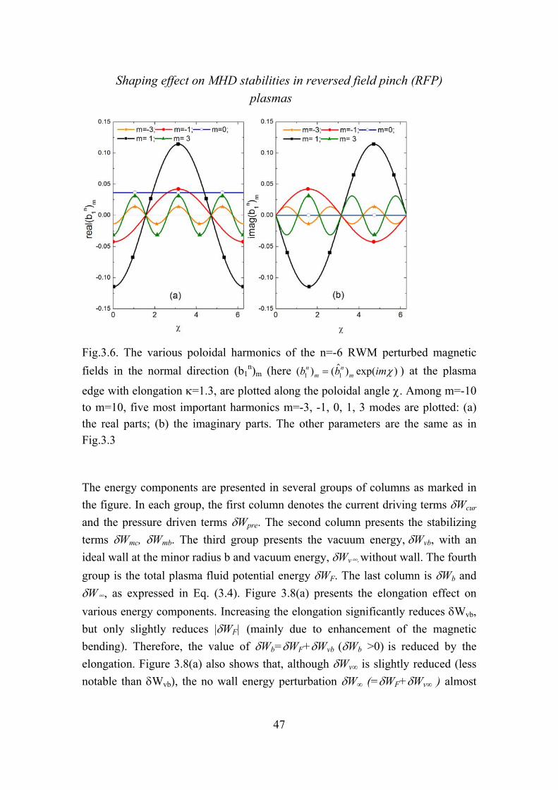
Shaping effect on MHD stabilities in reversed field pinch (RFP) plasmas
47
Fig.3.6. The various poloidal harmonics of the n=-6 RWM perturbed magnetic
fields in the normal direction (b1n)m (here 1 1( ) ( ) exp( )n n
m mb b im ) at the plasma
edge with elongation =1.3, are plotted along the poloidal angle . Among m=-10
to m=10, five most important harmonics m=-3, -1, 0, 1, 3 modes are plotted: (a) the real parts; (b) the imaginary parts. The other parameters are the same as in Fig.3.3
The energy components are presented in several groups of columns as marked in
the figure. In each group, the first column denotes the current driving terms Wcur
and the pressure driven terms Wpre. The second column presents the stabilizing
terms Wmc, Wmb. The third group presents the vacuum energy,Wvb, with an
ideal wall at the minor radius b and vacuum energy, Wv∞,without wall. The fourth
group is the total plasma fluid potential energy WF. The last column is Wb and
W∞, as expressed in Eq. (3.4). Figure 3.8(a) presents the elongation effect on
various energy components. Increasing the elongation significantly reduces Wvb,
but only slightly reduces |WF| (mainly due to enhancement of the magnetic
bending). Therefore, the value of Wb=WF+Wvb (Wb >0) is reduced by the
elongation. Figure 3.8(a) also shows that, although Wv∞ is slightly reduced (less
notable than Wvb), the no wall energy perturbation W∞ (=WF+Wv∞ ) almost
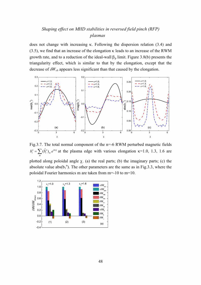
Shaping effect on MHD stabilities in reversed field pinch (RFP) plasmas
48
does not change with increasing . Following the dispersion relation (3.4) and
(3.5), we find that an increase of the elongation leads to an increase of the RWM
growth rate, and to a reduction of the ideal-wall p limit. Figure 3.8(b) presents the
triangularity effect, which is similar to that by the elongation, except that the
decrease of Wvb appears less significant than that caused by the elongation.
Fig.3.7. The total normal component of the n=-6 RWM perturbed magnetic fields
1 1( )n n imm
m
b b e at the plasma edge with various elongation =1.0, 1.3, 1.6 are
plotted along poloidal angle . (a) the real parts; (b) the imaginary parts; (c) the absolute value abs(b1
n). The other parameters are the same as in Fig.3.3, where the poloidal Fourier harmonics m are taken from m=-10 to m=10.

Shaping effect on MHD stabilities in reversed field pinch (RFP) plasmas
49
Fig.3.8. The potential energy components of the RWMs, which are normalized by
the driven term Wcur+Wpre, are plotted for n=-6 modes in RFP plasmas: (a)
comparison between the different elongations: group (1) is for the circular cross
section, group (2) is for elongated shape with =1.3 and group (3) is with =1.6.
The corresponding growth rates are 1=6.0710-4, 2=1.0210-3, 3=9.1510-3
respectively; (b) comparison between the circular RFP plasma (=0.0 in group(1)),
and triangle shaped RFP (=0.3 in group (2)), the growth rates are 1=6.0710-4,
2=8.4510-4. The other parameters are F=-0.06, q(0)=0.1448, p=0.07 and
b/a=1.12.
3.3 RWMinstabilityspectruminRFPplasma
3.3.1 Multipletrappingregions
An interesting observation is that, due to Bp ~BT in RFPs, the shaping effect causes a significant variation of the field strength along the poloidal angle, resulting in multiple trapping regions along the poloidal angle. Figure 3.9 is a 2-D plot of the values of the total magnetic field strength |B| on the shaped RFP cross
section with =1.3 and =0.3. The new areas where the lower magnetic strength
appears due to the shaping are marked as region 1, 2 and 3, respectively, in the figure. The strength of the normal field due to the toroidicity is not shown in this figure, the trapped fraction due to the toroidicity will be shown in figure 3.10(a) and denoted as “0”. Three new regions of the trapped particles appear in the shaped RFP plasmas, which are shown in Fig.3.10, where we plot the fractions of the trapped particle density (ntrap/ntotal, ntrap is the local trapped particle density and

Shaping effect on MHD stabilities in reversed field pinch (RFP) plasmas
50
and ntotal is the local total densities including the trapped particles and passing particles) in these regions on the cross-section: (a) the fraction of the usual trapping due to the toroidicity, which we denote as “trap 0”. (b) and (c) present the fractions of “trap 1 and 3” and “trap 2” resulted from both elongation and triangularity. Obviously the shaping effect increases the total fraction of trapped particles due to the appearance of the multiple trapping regions. Figure 3.11 shows the radial profiles of various fractions of the trapped particles in a shaped RFP, where the total trapped fraction and passing fraction are also presented as function of the magnetic flux coordinates. The data of Fig.3.11 are obtained by taking average over each magnetic flux surface. It shows that the total trapped fraction keeps increasing toward the edge of the shaped plasma, contrary to the circular cross section case where the total trapped fraction decreases towards the plasma edge [46]. Figure 3.12 plots the radial profiles of the bounce frequencies of trapped particles in different regions. The new trapped regions are located in a rather narrow area along the poloidal angle near the plasma edge, having higher bounce frequency than the nominal case. In particular, the particles of trap1&3 have bounce frequencies comparable or even larger than the transit frequency of the passing particles. The precession frequencies for both ions and electrons are also shown in the figure. The new trapped particles do not have substantially different precession frequencies w.r.t. the particles in “trap0”.
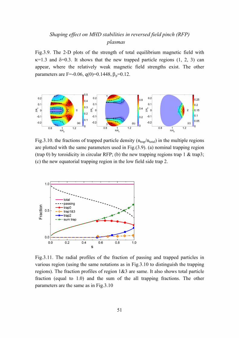
Shaping effect on MHD stabilities in reversed field pinch (RFP) plasmas
51
Fig.3.9. The 2-D plots of the strength of total equilibrium magnetic field with
=1.3 and =0.3. It shows that the new trapped particle regions (1, 2, 3) can
appear, where the relatively weak magnetic field strengths exist. The other
parameters are F=-0.06, q(0)=0.1448, p=0.12.
Fig.3.10. the fractions of trapped particle density (ntrap/ntotal) in the multiple regions are plotted with the same parameters used in Fig.(3.9). (a) nominal trapping region (trap 0) by toroidicity in circular RFP; (b) the new trapping regions trap 1 & trap3; (c) the new equatorial trapping region in the low field side trap 2.
Fig.3.11. The radial profiles of the fraction of passing and trapped particles in various region (using the same notations as in Fig.3.10 to distinguish the trapping regions). The fraction profiles of region 1&3 are same. It also shows total particle fraction (equal to 1.0) and the sum of the all trapping fractions. The other parameters are the same as in Fig.3.10

Shaping effect on MHD stabilities in reversed field pinch (RFP) plasmas
52
Fig.3.12. The radial profiles of the various frequencies of passing and trapped thermal particles in various regions (using the same region numbers as Fig.3.10).
The other parameters are P=0.12, =1.3 and =0.3. The transit frequency (m-
nq)p/n of the passing particles, the bounce frequencies of trapped particles in
various regions, denoted as b-0, b-1&3, and b-2.; the precession frequencies of
trapped ion di and electron de are presented. The embedded figure describes the
details of the precession frequencies contributed by various trapped regions, di_0,
di_1&3 and di_2 are for trapped ions and de_0, de_1&3 and de_2 are for trapped
electrons.
3.3.2 KineticdampingonRWMsinshapedRFPs
By taking into account the particle-wave resonance effects, the stabilization condition of RWMs can be written as [47]
2 2( ) ( ) ( ) 0re re imb k b k kW W W W W W W (3.6)
As expressed in Eq.(2.12), the kinetic energy Wk consists of the resonant
(imaginary) part Wkim and the non-resonant (real) part Wk
re, kW = rekW +i im
kW .
Generally, the imaginary part always gives a stabilizing effect. The real part can be either stabilizing or destabilizing. For RWMs, the first term in Eq.(3.6) is negative,
i.e. W∞Wb < 0, which is the most important destabilizing term contributed by the
fluid effects. The kinetic energy Wk usually has smaller value than the fluid

Shaping effect on MHD stabilities in reversed field pinch (RFP) plasmas
53
energy components. In such cases the kinetic effects can play a significant role
only when W∞ or Wb is very small (which leads to the first destabilizing term
(WbW∞) being small). This conclusion has already been obtained by a previous
analysis [27]. In RFPs, the shaping leads to a smaller Wb, therefore, the kinetic
effects become more significant than that in the circular case. Earlier studies [26,27] found that the RWMs in RFP could be kinetically stabilized mainly by the
transit resonance of passing (thermal) ions for a high p plasma, due to the ion
acoustic Landau damping. The required plasma rotation frequency for the stabilization is in the ion acoustic wave frequency range. Considering the shaping effects, we find that the transit resonance of passing ions is still the main mechanism for the kinetic stabilization of the RWM in RFPs. The (more
significant) kinetic effects result in a lower value, required for the full
stabilization, than that required in the circular case. As for the plasma rotation needed for the stabilization, the elongation leads to slightly smaller rotation frequency; whilst the triangularity leads to a slightly larger rotation frequency for the mode stabilization, compared to that of the circular RFP. Figure 3.13 plots the
mode growth rate versus the normalized plasma rotation frequency o (o=/A,
where A is the Alfven frequency calculated at the magnetic axis) under various
kinetic effects, such as the transit resonance of passing ions, the precession and bounce resonances of trapped particles, and the full kinetic contributions from both passing and trapped particles. The results of the fluid theory are also plotted for comparison. Figure 3.13(a) is for the circular plasma and (b) is for a plasma
with elongation =1.3. It is found that the stabilization of the RWM for the n=-6
mode in the circular plasma requires a higher p value, p=0.15, and a rotation at
o=0.025 under the full kinetic effects, whilst for the shaped plasma with =1.3,
the required p value is lower, with the stabilization found at p=0.12. The critical
rotation frequency for full stabilization is also slightly decreased from 0.025 to 0.024. The transit resonance of passing ions is the dominant kinetic stabilization mechanism for both cases. The new trapped regions enhance the damping by enhanced bounce resonances, as shown in Fig. 3.13(b). On the other hand, the stabilization by these new bounce resonance regimes requires higher rotation frequency than the transit damping; we do not consider these new regimes as the principle mechanism for stabilizing the RWM in RFP. However, the multiple
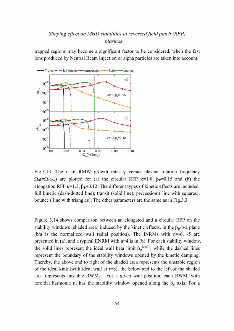
Shaping effect on MHD stabilities in reversed field pinch (RFP) plasmas
54
trapped regions may become a significant factor to be considered, when the fast ions produced by Neutral Beam Injection or alpha particles are taken into account.
Fig.3.13. The n=-6 RMW growth rates versus plasma rotation frequency
0(=/A) are plotted for (a) the circular RFP =1.0, P=0.15 and (b) the
elongation RFP =1.3, P=0.12. The different types of kinetic effects are included:
full kinetic (dash-dotted line); transit (solid line); precession ( line with squares); bounce ( line with triangles); The other parameters are the same as in Fig.3.3.
Figure 3.14 shows comparison between an elongated and a circular RFP on the
stability windows (shaded area) induced by the kinetic effects, in the p-b/a plane
(b/a is the normalized wall radial position). The INRMs with n=-6, -5 are presented in (a), and a typical ENRM with n=4 is in (b). For each stability window,
the solid lines represent the ideal wall beta limit pideal ; while the dashed lines
represent the boundary of the stability windows opened by the kinetic damping. Thereby, the above and to right of the shaded area represents the unstable region of the ideal kink (with ideal wall at r=b); the below and to the left of the shaded area represents unstable RWMs. For a given wall position, each RWM, with
toroidal harmonic n, has the stability window opened along the p axis. For a

Shaping effect on MHD stabilities in reversed field pinch (RFP) plasmas
55
given p value, each n mode has a stability window in b/a axis. Within stable
windows, if both p and b/a are given, only one critical rotation frequency c
(normalized by A) will be found correspondingly. The critical rotation
frequencies c marked in the figures correspond to the required rotation at the
smallest b/a points (highest p) of the dashed lines. More complete data of each
stability boundary are listed in Table 1. It is shown that elongation makes the kinetic damping more efficient, and thus the stability window opened in the lower
p region with a slightly slower rotation frequency than the circular one. For
INRMs, elongation leads to narrower stability windows in both p and b/a
parameter spaces. For ENRMs, shown in (b), the kinetic effects provide a rather
wide stability window except at very low p, where a rather fast plasma rotation is
required for the mode stabilization. For n=4 mode, c is around 0.17-0.285 with a
wall at b/a=1.35 for the circular RFP, and c ~0.26-0.32 with b/a=1.2 for the
=1.3 non-circular case. Higher critical rotation c is required if the wall is closer to the plasma. These rotation ranges are much faster than that of the presently operating RFP plasmas without external momentum sources such as that from the tangential neutral beam injection.

Shaping effect on MHD stabilities in reversed field pinch (RFP) plasmas
56
Fig.3.14. The stability windows in the plane of the poloidal beta P vs. wall
position b/a are plotted for both INRMs and ENRMs (a) INRMs n=-6,-5 with
=1.0 and 1.3, =0.0, F=-0.06 q(0)=-0.1448 and (b) EXRMs n=4 with =1.0 and
1.3, =0.0, F=-0.9, q(0)=0.1448. The solid lines present the ideal wall beta limits
pideal and the dash lines express the boundaries of the stability window opened by
kinetic damping. The c values marked in the figures are the required rotation frequencies corresponding to the points having the smallest b/a on the dashed lines.. The more completed data including all other points are listed in Table 1.
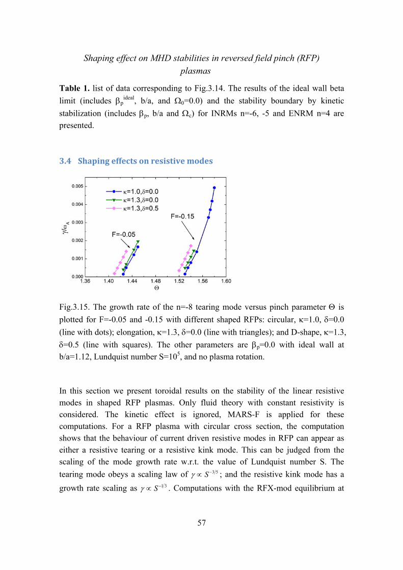
Shaping effect on MHD stabilities in reversed field pinch (RFP) plasmas
57
Table 1. list of data corresponding to Fig.3.14. The results of the ideal wall beta
limit (includes pideal, b/a, and =0.0) and the stability boundary by kinetic
stabilization (includes p, b/a and c) for INRMs n=-6, -5 and ENRM n=4 are
presented.
3.4 Shapingeffectsonresistivemodes
Fig.3.15. The growth rate of the n=-8 tearing mode versus pinch parameter is
plotted for F=-0.05 and -0.15 with different shaped RFPs: circular, =1.0, =0.0
(line with dots); elongation, =1.3, =0.0 (line with triangles); and D-shape, =1.3,
=0.5 (line with squares). The other parameters are p=0.0 with ideal wall at
b/a=1.12, Lundquist number S=105, and no plasma rotation.
In this section we present toroidal results on the stability of the linear resistive modes in shaped RFP plasmas. Only fluid theory with constant resistivity is considered. The kinetic effect is ignored, MARS-F is applied for these computations. For a RFP plasma with circular cross section, the computation shows that the behaviour of current driven resistive modes in RFP can appear as either a resistive tearing or a resistive kink mode. This can be judged from the scaling of the mode growth rate w.r.t. the value of Lundquist number S. The
tearing mode obeys a scaling law of 3 5S ; and the resistive kink mode has a
growth rate scaling as 1 3S . Computations with the RFX-mod equilibrium at

Shaping effect on MHD stabilities in reversed field pinch (RFP) plasmas
58
zero find that, for the most long wave length modes (mode’s rational surface is
near the magnetic axis) such as the n=-7 and n=-8 modes, the growth rates approximately follow the tearing scaling law when S>106, and the resistive kink scaling when S<106. As for the shorter wavelength modes, such as n=-11, -12…, the mode growth rates almost follow the tearing scaling only. In the following analysis, we will not distinguish these two, simply labelling them the resistive mode.
Fig.3.16. The stability boundary of n=-8 tearing mode are plotted in F- plane
obtained by MARS-F. For circular cross section =1.0 =0.0 (dash-dot line),
elongation =1.3, =0.0 (triangle point), and D-shape =1.3, =0.5 (diamond point)
RFPs. Experiment data (dot point) and the results from cylindrical code (solid-line) also plotted for comparison. The other parameters used are the same as in Fig.3.15.
The shaping effect can also enhance the poloidal mode coupling for the resistive mode. In this case, the resonant tearing mode (m=1) coupled mostly with the non-resonant modes (rational surfaces outside the plasma), e.g. m=2, -1,-2,…etc. We find that shaping can moderately increase the mode’s growth rate; but cannot
significantly change the stability boundary in the F- plan. Shown in Fig. 3.15 is
the growth rate of the n=-8 mode at S=105 and zero , plotted as a function of the
pinch parameter (a larger value implies a more peaked current profile,
=Bp(a)/<BT>). An ideal wall at b/a=1.12 is assumed. Both elongation and
trangularity result in a larger growth rate than the circular case. The stability

Shaping effect on MHD stabilities in reversed field pinch (RFP) plasmas
59
boundaries have also been investigated and compared with experimental data. It is
necessary to point out that, for each RFP machine, the parameters F and cannot
change independently for all discharges. It has been found that all the discharges
follow a fixed F - curve (F is a monotonic function of ) [35,36,48,49]. We
selected 4 points of experimental data on the F- curve, as presented in Ref.[36],
which have the reversal parameter F=-0.05,-0.1,-0.15, -0.2; and the corresponding
values on the curve are =1.42, 1.49, 1.57, 1.63 as plotted in Fig. 3.16. The n=-
8 resistive mode’s stability boundary is computed by MARS-F, and compared
among several cases: circular (=1.0, =0.0), elongated (=1.3, =0.0) and D-
shaped (=1.3, =0.5). A cylindrical code is also used for a reference. The figure
shows that the RFP experiments operate near the tearing mode stability boundary (marginal stable tearing mode). This is agreed with the previous observations [50]. Since the tearing modes are consider as the dynamo modes, this can be understood as the results of the self-organized relaxation in RFP plasmas through the dynamo effects. As shown in Fig. 3.16, the shaping effects do not significantly change the
stability boundary in the F- plan, and hence cannot influence much the operating
state of the dynamo system. The eigenfunctions Qm1 of the n=-8 resistive mode are
plotted in Fig. 3.17, with elongation of =1.3 and various wall conditions: without
wall, with an ideal wall, and with a resistive wall with the penetration time of w
/A~6.4103(A=1/A). The corresponding growth rates (normalized by A) of the
modes are =3.24610-2, =4.9910-4 and 1.27510-3, respectively. It is obvious
that the ideal wall results in the smallest growth rate; the no-wall condition gives the largest growth rate; and the resistive wall result stays in the middle.

Shaping effect on MHD stabilities in reversed field pinch (RFP) plasmas
60
Fig.3.17. The eigenfunctions of perturbed magnetic fields in normal direction for
n=-8 tearing mode with elongation =1.3 are plotted for different wall conditions
such as: no-wall (dotted line) with the growth rate =3.24610-2, ideal-wall (solid
line)=4.9910-4, and resistive-wall (dash-dot line) =1.27510-3. Various
poloidal harmonics are shown. The embedded figure presents the whole
eigenfunctions for no-wall case, The parameters are F=-0.05, q(0)=0.15,=1.43.
This can also be seen from the derivative jumps of the eigenfunction Qm1 (the
radial component of the magnetic perturbation). Assuming the same values of Q1
m=1 at the rational surfaces for all the three cases, the no-wall boundary condition gives a much larger amplitude of the perturbation outside the rational surface.
We point out that the marginal tearing mode state obtained by MARS-F has a slight discrepancy with the experimental data. This may be due to the fact that the model equilibrium current profile used by MARS-F does not perfectly match the real experimental current profile, which currently cannot be directly measured yet. However, the conclusion of the shaping effects on the tearing stability boundary is not altered by this fact.
3.5 ShapingonBootstrapcurrentinRFPs
In RFPs, the bootstrap current fraction is much smaller than that in Tokamaks, due to the strong poloidal field Bp. For the same on-axis BT amplitude, the poloidal field Bp, and hence the total current Itotal in a circular RFP is approximately one
order of O(-1) larger than a circular tokamak with the same geometry.
Furthermore, it is well known that the density of the bootstrap current jBT is
proportional to Bp-1, BT
p
1 dpj
B dr , hence for a given pressure profile, the total
plasma bootstrap current IBT is scaled to Bp-1 too. However, the total plasma
current is scaled as Itotal ∝ Bp. Therefore, the fraction of the bootstrap current IBT
/Itotal should approximately satisfy the scaling of BT2
total p
I 1
I B . Considering the fact
that the pressure gradient (dp/dr) can generally be of the same order in both RFP and Tokamak, the fraction of trapped particles in a circular RFP is smaller than

Shaping effect on MHD stabilities in reversed field pinch (RFP) plasmas
61
that in a circular tokamak with the same geometry [46], we arrive at a conclusion
that the bootstrap current fraction of RFP is at least O(2) smaller than the fraction
of the circular tokamak with same BT at the axis
2BT BT
total totalRFP tokamak
I I
I I
The shaping effect can increase the fraction of the bootstrap current. The results of computation by the CHEASE code, using the Hirshman model [51], are presented in Fig. 3.18, showing the profiles of the normalized total current density and the bootstrap current density under various types of shaping, and comparing with the circular case results. The bootstrap current fractions IBS/Itotal are also marked in the figure. Only a very small fraction bootstrap current, around a few percent, can be achieved in RFP. Shaping increases this fraction by 10% to 30% more than the circular value. However, the eventual fraction still remains the same order. The similar results showing the very small BT fraction are obtained by previous calculations in a circular RFP plasmas by using different models [46,52]. We point out that these characteristics are resulted from the intrinsic nature of the RFP configuration. The speculation about a significant enhancement of BT fraction by increasing the temperature of RFP plasmas seems be not realizable due to the unfavourable scaling for the plasma generated BT current. Therefore, in future RFP fusion reactors, for a steady state operation, the external current drives will be probably necessary.

Shaping effect on MHD stabilities in reversed field pinch (RFP) plasmas
62
Fig.3.18. The normalized radial profiles of the bootstrap currents density <J*B>BS (with different shaped RFP plasmas, are plotted to compare with total plasma current density <J*B>total. The total current is expressed by solid line, and the boots trap currents under different shapes are expressed by 30 times amplification:
circular cross section =1.0, =0.0 (short dash-dotted line); elongation =1.3,
=0.0 (dash-dotted line); triangularity =1.0, =0.3 (dotted line); and D-shape
=1.3, =0.5 (dashed line). IBS/Itotal represents the fraction of the bootstrap current.
The parameters used in calculation are F=-0.06, q(0)=-0.1448, and p=0.12.
The regime of the new multiple trapping regions is not considered in this calculation. This may lead to a slight underestimation of the fraction of the bootstrap current, but will not result in any significant change of the conclusion.
3.6 Summary
We have studied the shaping effects on RFP plasmas by using the MHD-kinetic hybrid toroidal stability code MARS-K. Both elongation and triangularity effects have been investigated. The studies focus on the most important MHD modes in
RFPs. The first topic is the p limit set by the RWM (the ideal kink mode)
instability, where the ideal-wall limit and the stabilization by drift kinetic
damping are studied; and an in-depth analysis has been carried out for physics understanding. The second topic is on the linear stability of the resistive mode (the
dynamo modes) under shaping effects in the low RFP plasmas, and the comparison with the circular case. Finally we report a computational result on the bootstrap fraction in shaped RFP plasmas.
The RFP magnetic configuration is characterized by a strong poloidal magnetic field and reversed toroidal field. Shaping effects in RFP induce a stronger poloidal mode coupling than the circular case, due to the variation of the poloidal field strength along the poloidal angle. Moreover, shaping also introduces multiple trapped regions. As a consequence, the shaping effects lead to quite a different conclusion from that of a tokamak. The detailed results are summarized as follows.
For the RWM, shaping yields a lower ideal-wall limit, and increases the growth
rate of the mode due to the reduction of the vacuum energy component Wvb. In

Shaping effect on MHD stabilities in reversed field pinch (RFP) plasmas
63
this case, the kinetic damping becomes more significant than the circular case,
meaning that the kinetic stabilization requires a lower p value, and possibly also a
slightly slower rotation. However, the kinetic contribution is still dominant by the ion acoustic Landau damping of passing particles, thus requiring a critical plasma rotation still in the ion acoustic frequency range. Furthermore, the stabilization
windows in shaped RFP become narrower in both p and b/a parameter spaces.
Appearance of multiple trapping regions due to the shaping can enhance the bounce resonance damping, which, nevertheless, is not the dominant damping mechanism for the RWM in thermal RFP plasmas.
For the linear resistive modes in low RFP, shaping induced poloidal coupling
only moderately increases the growth rate, without significantly influencing the
stability boundary of the mode in the F- plan. The self-organized RFX plasma in
a relaxation process operates along a fixed F- curve, which is near the marginal
stable state of the tearing modes. Since the shaping effects do not give a notable change to the stability boundary, we may conclude that shaping in RFP cannot introduce a notable change to the state of the dynamo system.
The RFP configuration yields a much smaller (order of (2)) fraction of the
bootstrap current than that in tokamaks. Although shaping can increase the bootstrap fraction by up to 30%, the eventual fraction in shaped plasmas still remains the same order as that in a circular RFP. Therefore, in order to reach steady state RFP fusion reactors, a substantial fraction of external current drives would be necessary, because the unfavourable scaling for the plasma generated bootstrap current in the RFP configuration.
Based on the results from the above studies, we conclude that the present circular cross section design for RFPs is an appropriate choice, in the sense that no notable improvement for the RFP performance seems to be gained by shaping the plasma cross section. The major physics reason is the strong poloidal field in RFP (compared to the toroidal field), which plays an important role in the poloidal mode coupling and the particle dynamics, in particular, prevents the access to a substantially improved good averaged curvature by shaping.
The new multiple trapped regions appear in the shaped RFP configuration. Although these regions do not significantly modify the RWM stability in thermal
Shaping effect on MHD stabilities in reversed field pinch (RFP) plasmas
64
plasmas, they can still be the notable phenomena which may influence the energetic particle physics and the other kinetic driven instabilities in a shaped RFP.
The resistive tearing mode studied in this work is only for very low RFP plasmas.
The effects of high and energetic particles, as well as the corresponding kinetic
effects, have not been taken into account. These will be studied in a future works. The behaviour of the nonlinear dynamics of resistive tearing mode under the shaping effects is still unknown, which is beyond the scope of the present work. In particular, the variation of the single helical phase due to the shaping is interesting topic to be studied.
The kinetic effect of the Energrtic Paricles (EPs) on the RWM instability in RFP plasma, compared with the Tokamaks
65
Equation Chapter (Next) Section 1
Chapter 4
4 The kinetic effect of the Energrtic Paricles (EPs) on the RWM instability in RFP plasma, compared with the Tokamaks
It is important to understand the physics of the RWMs, in order to achieve the successful operation of the present devices and the optimized design of the future reactor (such as ITER). The ideal kink mode is global instability, and can be completely stabilized by surrounding an ideal conducting wall which is closed enough to the plasma. However, it becomes a slowly growthing RWM instability by surrounding the finite conducting wall in reality. The RWM is the most
important instability to set a limit of the plasma pressure ( -limit) for the
advanced Tokamak [17, 18], such as ITER. In the Reversed Field Pinch (RFP) plasma, the RWMs casue the disruption when the discharge duration is longer than the penetration time of the resistive shell. The RWM can be suppressed by the dissipation due to the kinetic resonance of the mode with the drift motion of the particles, which has been observed in many experiment and theory studies [47,53,54,26,27]. As studied in the previous work [27], it is found that the RWM is stabilized at the very low plasma rotation in the Tokamak plasma, due to the mode resonance with precession drift motion of the trapped particles. On the other side, the stability of the RWM is also predicted in the RFP plasma [26, 30], due to the ion acoustic Landau damping, and requires much higher rotation frequency than the Tokamak case.
The energetic particles (EPs), which are the energetic ions (EIs) from the neutral beam injection (NBI) or the alpha particles from the fusion reaction, expected to play major role in achieving optimal burning plasma scenarios with external

The kinetic effect of the Energrtic Paricles (EPs) on the RWM instability in RFP plasma, compared with the Tokamaks
66
heating and/or current drive [55]. As shown in many theory studies of the tokamaks plasma (Such as NSTX advanced tokamak or the simply circular case) [56,57,58,59], the beam ions leads to an important effect on the RWM, compared with the kinetic damping fo thermal particles alone. And it is found that the alpha particles theoretically lead to the better stabilization of the RWMs in an ITER equilibrium [60]. On the contrary, these effects on the RWMs in the RFP plasma have not been investigated with clearly physical understanding or experiment results. Therefore in the present work, the kinetic effect on RWM in the RFP plasma is extended by including the effects of the energetic particles, in particular beam ions, and the full kinetic mechanism, which includes both thermal particles and EIs, is also investigated. The comparion between the RFP and tokamak configurations, with the same circular cross section and similar equilibrium parameters, is also investigated in order to achieve better physical understanding on the issue.
In this work, the upgrade kinetic-MHD hybrid toroidal code MARS-K is used to the studies, taking into account the drift kinetic effect of the thermal particles as well as the isotropic/anisotropic EIs [61,62,40,63]. Firstly, we find that the RWM can be stabilized by the mode resonance with precession drift motion of the trapped isotropic EIs alone in the RFP plasma. By considering the full kinetic effect, it is found that there is the cancellation of the kinetic effect between two species. Furthermore, more detailed analyses are carried out by discussing the influence of the equilibrium parameters of the EIs. It is found that the critical rotaion frequency is reduced by reducing the birth energy of EIs, which reduces the precession frequency and modifies the resonance region in the velocity space. It is also found that the anisotropy of the EIs provides an impotant impact on the results. The increased fraction of the trapped EIs leads to enhance the cancellation of the kinetic effect between two species and reduce the stabilization of the RWMs, when the dominated contribution comes from the thermal paricles. On the other side, if the kinetic comtirbution of the EIs becomes dominated, the increased fraction of the trapped EIs leads to enhance the stabilization of the RWMs. Therefore, with the presence of the EPs in the plasma, the condition of the stabilization of RWMs by kinetic damping depends on the parameters of the two species. Finally, the effect of the EIs on the RWMs is studied in the Tokamaks

The kinetic effect of the Energrtic Paricles (EPs) on the RWM instability in RFP plasma, compared with the Tokamaks
67
(similar geometry), compared with the RFP case. The results show that the characteristic of the EIs in the Tokamak is similar to the RFP case.
The paper is organized as following. Section 4.1 investigates the effect of the isotropic EIs on the RWMs, compared with the thermal particles in the RFP plasma. Section 4.2 shows the anisotropic distribution of the EIs, and its effects are studied compared with isotropy case in the RFP plasma. In section 4.3, the results in the tokamak case is calculated and compared with the RFP case. The conclusion and the discussion are given in the section 4.4.
4.1 KineticeffectsofEPswith isotropicdistributiononRWMs inRFPplasma
In this study, we study the kinetic effects of energetic ions with isotropic distribution on the RWMs stabilization in RFP plasma. For thermal particles, various kinetic mechanisms are taking into account as shown in the resonance oparetor Eq.(2.8), including the precession motion of both the trapped ions and the electrons, the bounce motion of trapped ions, and the circulating (transit resonance) of the passing ions. The dominated kinetic damping is contributed by the transit resonance of the passing ions as studied in the previous work [27]. For energetic ions, only the precession resonance of the trapped EIs is considered. The kinetic effects of the bounce and transit resonance of the EIs (as well as that of the thermal electrons) are neglected, due to their extremely high frequency. The kinetic mechanism of both thermal particles and EIs is so call full kinetic mechanism in the following sections.
4.1.1 Theequilibriumparameters
The investigation is carried out by using the parameters of the RFX-mod
experiments, which are the inverse aspect ratio / 0.2295a R , the reversal
parameter F=-0.06 ( ( )/F B a B ) and the resistive wall position b/a=1.12.
There are two type of RWMs in the RFP plasma: one is the so-call “externally non-resonant” modes (ENRM) with the rational suface located at q<q(a)<0; the other one is “internally non-resonant” modes with q>q(0)>0 (INRM). Under the parameters mentioned above, the most important unstable RWM is n=6 INRM with the dominated poloidal harmonic number m=-1, which has closest resonance surface to the plasma and is easiest to be stabilized. The safety factor at the plasma

The kinetic effect of the Energrtic Paricles (EPs) on the RWM instability in RFP plasma, compared with the Tokamaks
68
center q(0) is equal to 0.1448 (q(a)~-0.01) and the rational surface of the mode is located at q=-m/n=0.1667.
The poloidal plasma beta P is chosen as 0.155P . Where 2
0
8P totP V
I R
, I
is the plasma current, P is the volume averaged plasma pressure and 2 totV is
the total plasma volume. It is closed to the ideal wall beta limit 0.16idealP at
b/a=1.12 ( idealP P ), and the kinetic effect plays an important role on stabilizing
the RWMs. The slowing-down distribution function is used to describe the
isotropic EIs, with the constant birth energy profile and fraction profile of the
pressure Pa/Pth. The electron density at the plasma core is chosen as 19 3
0 2 5 10en . / m . We take Pa/Pth=constant along the minor radius, and the
* thP P/ is equal to the pressure fraction Pa/Pth = 0
* , for example, 0 0 3* . and
0 3* . as shown in the figure.(2.1). The equilibrium (a) pressure (normalized by
the 20 0B / ) and (b) density profiles (normalized by the Ne(0) at the magnetic axis)
are plotted in the figure.(2.1), for the thermal ions and electrons as well as the energetic ions respectively.
4.1.2 DispersionrelationoftheRWMs
The dispersion relation of the RWM, which is relevant to the energy analysis [44,45], is written by,
* kW
b k
W W
W W
(4.1)
Where F vW W W and b F vbW W W ( 0FW and , 0v vbW W ). is
the mode growth rate and *W characterizes the penetration time of the resistive
wall. By taking into account the particle-wave resonance effects, the stabilization condition of RWMs can be written as [47],
2 2( ) ( ) ( ) 0re re imb k b k kW W W W W W W (4.2)
As expressed in Eq.(2.12), the kinetic energy kW consists of the resonant
(imaginary) part imkW and the non-resonant (real) part re
kW , re imk k kW W i W .

The kinetic effect of the Energrtic Paricles (EPs) on the RWM instability in RFP plasma, compared with the Tokamaks
69
Generally, the imaginary part imkW always gives a stabilizing effect. The real part
can be either stabilizing or destabilizing effect. For the RWMs, the first term in
Eq.(4.2) is negative, where 0bW W . It is the most important destabilizing term
contributed by the fuild effects. The kinetic energy kW has smaller value than the
fuld energy components. In such cases, the kinetic effects can become stronge
relatively only when W or bW is very small, which leads to the first
destabilizing term bW W being small. The conclusion has already been obtained
by a previous analysis [27].
4.1.3 Stabilization of the kinetic effect of the EIs, comparedwith thethermalparticles
As shown in the figure.(4.1), we plot the n=6 RWM growth rate / A versus the
normalized plasma rotation frequency / A (where A is the Alfven frequency
calculated at the magnetic axis) in both positive / 0A (same direction to the
plasma current) and the nagative direction / 0A . The kinetic effect
contributed by the EIs with its birth energy 100keV and the beta ratio * 0.3
is taken into account. The kinetic contribution from EPs with/without thermal particles are considered and compared to the case with the kinetic effect of the thermal particles alone. In the figure.(4.1-a), we find that the RWMs can be stabilized by the precession resonance of the EIs alone at the critical rotation
frequency / 0.039C A in the opposite direction. The similar stabilization can
be obtained by the kinetic damping of the thermal particles alone (dominated by
the transit resonance of passing ions and * 0.0 ). On the contrary, the influence
of EIs on the RWM stability is neglected in the positive direction, as shown in the figure.(4.1-b). The RWMs by taking into account the kinetic effect of the thermal
particles alone is stabilized at / 0.022C A , which has been found in the
previous results [27]. Furthermore, by considering the full kinetic mechanism (including the kinetic effect of both speices), the required critical rotation
frequency C is increased for the case / 0A , even though the mode
resonance with the kinetic motion of each particle species alone gives a stabilizing effect on RWMs. In the other direction, the EIs give the negligible modification to the stabilization of the RWMs contributed by the thermal particles. The results

The kinetic effect of the Energrtic Paricles (EPs) on the RWM instability in RFP plasma, compared with the Tokamaks
70
indicate that the precession resonance of the EIs occurs only if / 0A . And
when it occurs, a slight cancellation of the kinetic effect between the thermal particles and the EIs may exist in the RFP plasma. The physical understanding will be in the following sections.
-0.10 -0.08 -0.06 -0.04 -0.02 0.0010-4
10-3
10-2
10-1
P=0.155,*=0.3,
=100keV,F=-0.06,q0=0.1448,b/a=1.12,n=6
thermal particles only EPs only full kinetic
/
A
/A
(a)
0.00 0.02 0.04 0.06 0.08 0.1010-4
10-3
10-2
10-1
P=0.155,*=0.3,
=100keV,F=-0.06,q0=0.1448,b/a=1.12,n=6
/
A
/A
thermal particles only EPs only full kinetic
RWM
(b)
Figure 4.1. The n=6 RWM growth rate / A versus the plasma rotation frequency
/ A , with the comparision of the drift kinetic stabilization of the RWM from
EPs (red line) and thermal particles (black line) separately, and from both species
combined (full kinetic, blue line), in both direction: (a) / 0A and (b)
/ 0A for the RFP plasma. The birth energy of EPs is 100keV , and its beta
ratio is * 0.3 . The other equilibrium parameters are chosen as the previous
description.
0.0 0.2 0.4 0.6 0.8 1.0-0.02
0.00
0.02
0.04
0.06
0.08
0.10
<
i>/
A
s
di,
de,
da
(m-nq)p/n,
b/n
P=0.155,*=0.3,
=100keV
Figure 4.2. The radial profiles of various frequencies of each species over the velocity space and over the poloidal angle are plotted, including the transit
frequency ( ) /pm nq n of the thermal passing particles, the bounce frequency

The kinetic effect of the Energrtic Paricles (EPs) on the RWM instability in RFP plasma, compared with the Tokamaks
71
/b n and the precession frequency ,di de of the thermal trapped particles, as
well as the precession frequency d of the trapped EIs with their birth energy
100keV . The equilibrium parameters are chosen as the previous description.
In the figure.(4.2), we plot the radial profile of each frequencies averaged over the velocity space and the poloidal angle. Several types of the resonance frequency as mentioned previously are included for each species. For thermal particles, the dominated kinetic contribution from the transit resonance becomes significant
when the resonance condition ( ) / 0 ( 0)pm nq l n l is satisfied. The
resonance occurs in both positive and opposite direction, and the axymmetric kinetic effects on the RWMs is due to the difference of the numerator in the
resonance operator Eq.(2.8) for the 0 and 0 cases. For EIs, the condition
of the mode resonance with the precession drift of trapped EIs is 0d . As
shown in the figure.(4.2), the averaged precession frequency of trapped EIs is
positive, and this indicates that the resonance only occurs when 0 . Figure (4.2)
also shows the approximate frequency regions: , ~ 0.01di de A ,
/ ~ 0.01 0.03b An , ( ) / ~ 0.02 0.06p Am nq n for thermal particles and
~ 0.02 0.05d A for EIs. The critical rotation frequency shown in the figure.(4.1)
is in the region / ~ 0.04C A , and conditions of the dominated resonance for
each species are satisfied. The precession frequency of EIs with birth energy
100keV is much larger than that of thermal particles, due to its large energy.
And it is found that this frequency has similar region to the transit frequency of the passing thermal ions. This possibly leads to the slight cancellation of the kinetic effects between each species as observed in the figure.(4.1).
Figure.(4.3) shows the imaginary kinetic energy components imkW contributed
from the various types of particles and their combined energy (full kinetic). The
imaginary part of the kinetic energy imkW always plays the most important role on
the stabilization of the RWMs, which is analysed in the stabilization condition Eq.(4.2). For thermal particles, the kinetic energy is contributed by the sum of the transit resonance of the passing ion, the bounce resonance of the trapped ions and the precession resonance of the trapped electrons and the ions. For EPs, the kinetic

The kinetic effect of the Energrtic Paricles (EPs) on the RWM instability in RFP plasma, compared with the Tokamaks
72
energy is contributed by the precession of the trapped EIs alone. As shown in the figure.(4.1-b), the precession resonance of the EIs does not occurs in the case
/ 0A , where the resonance condition is not satisfied and the imaginary part of
the kinetic energy imkW is equal to zero. The total stabilization contritbution
2( )imkW in Eq.(4.2) comes completely from the thermal particles, and the EIs does
not give the influence to the RWM stability.
-0.06 -0.05 -0.04 -0.03 -0.02 -0.01 0.00-0.14
-0.12
-0.10
-0.08
-0.06
-0.04
-0.02
0.00
0.02
0.04
0.06
0.08
0.10
P_total=0.155,*=0.3,
=100keV
kinetic energy components
thermal kinetic precession_EPs full kinetic
imag
(W
k)/W
2
/A
(a)
0.00 0.01 0.02 0.03 0.04-0.14
-0.12
-0.10
-0.08
-0.06
-0.04
-0.02
0.00
0.02
0.04
0.06
0.08
0.10
thermal kinetic precession_EPs full kinetic
kinetic energy components
P_total=0.155,*=0.3,
=100keV
ima
g(W
k)/
W2
/A
(b)
Figure 4.3 The imaginary parts of the kinetic energy imkW , including the kinetic
components of each species and the total kinetic energy of both species conbined
in two direction: (a) / 0A and (b) / 0A , are plotted as the function of the
rotation frequency, with the parameters same as figure.(4.1).
In the direction / 0A , as shown in the figure.(4.1-a), the kinetic contribution
to the RWM stability becomes significant when the plasma rotation frequency
| / |A is larger than 0.03. In high rotation region | / | 0.03A , the energy im
kW of the EIs is increased to the same order of the thermal particles by
increasing the rotation frequency, and the stability of the RWM is achieved by considering the kinetic contribution from each species alone. By considering the full kinetic effect, it is found that there is a cancellation of the imaginary part of
the kinetic energy imkW between the thermal particles and the EIs, which leads to
reduce the total kinetic damping compared to the single species respectively. However, this reduced full kinetic effect is still large relatively to stabilize the
RWMs, which maybe due to the reduced destabilizing term ( 0)bW W in the
stabilization condition Eq.(4.2) by increasing the plasma rotation frequency. In the

The kinetic effect of the Energrtic Paricles (EPs) on the RWM instability in RFP plasma, compared with the Tokamaks
73
low rotation frequency region | / | 0.02A , the dominated contribution is the
transit resonance of the thermal ions, which is enhanced slightly by the precession resonance of the EIs. But as the results, the stabilization of the RWMs does not occur. This is possibly because of the very large destabilizing contribution in the
low rotation frequency region (in Eq.(4.2)), and the stabilizing term 2( )imkW is not
large sufficiently, compared to the high plasma rotation region.
( a ) ( b )
Figure 4.4. The 2-D plots of (a) the precession frequency of the EIs (averaged over the velocity space), and (b) the imaginary parts of the kinetic energy of EIs at the
plasma rotation frequency / 0.035A , in the R-Z plane. The equilibrium
parameters are chosen as the previous description.
In the figure.(4.4-a), the particle phase space averaged precession frequency of the trapped EIs is plotted in the R-Z plane. It is found that the precession frequency
stay in a large region (yellow region) with its amplitude close to ~ 0.03 0.04d .
A small region at the plasma center where the value of precession frequency is very large and its sign changes between the high and low field side, is also
observed. Figure.(4.4-b) shows the imaginary parts of the kinetic energy imkW
contributed by precession resonance of the EPs at the rotation frequency
/ 0.035A , in the R-Z plane. By comparing two figures, we find that the
resonance contribution at / 0.035A comes almostly from the yellow regions
in the figure.(4.4-a), where the resonance condition 0d can be satisfied

The kinetic effect of the Energrtic Paricles (EPs) on the RWM instability in RFP plasma, compared with the Tokamaks
74
generally. The imaginary kinetic energy imkW locates at the low field side near the
plasma core. This is due to the contribution of the dominated m=-1 harmonic, which has large amplitude in this region as studied in the previous work [27]. Furthermore, the distribution of the kinetic energy from EIs is similar to that from the transit resonance of the thermal ions, but has the opposite sign of the amplitude. As the results, it causes the cancellation of the kinetic damping between two species inevitable.
4.1.4 StabilizationofthekineticeffectoftheEIswithitsdifferentbirthenergy
The kinetic effect of the EI with its differet birth energy 50 ,150keV keV is
investigated as shown in the figure.(4.5), comparing with the 100keV case
which we used above. The density profiles of the EIs (Na/Ne=0.18 at the plasma center, Na is normalized by the electron density Ne) keep almost unchanged for
the cases with various birth energy , and thus the beta ratio * (=0.135 (50keV),
0.3(100keV), 0.51(150keV)) is increased by increasing the birth energy . It
leads to increase the precession frequency of the EIs, and the kinetic energy ikW
from EIs which is roughly proportional to its equilibrium pressure ( * ) as shown
in Eq.(2.12). In the figure.(4.5-a), the growth rate of the n=6 RWMs is plotted versus the plasma rotation frequency, by considering the kinetic contribution from the EIs with/without the thermal particles. By considering the kinetic effect of the EIs alone, it is found that the critical rotation frequency is increased with the
increased birth energy of EIs . In particular, the critical rotation frequency is
/ A =-0.021, -0.039, -0.05 corresponding to the case =50keV, 100keV,
150keV respectively, and they are coinciding with the averaged precession frequency of the EIs as shown in the figure.(4.5-b). Moreover, it is found that the cancellation of the kinetic effect between two species still exists by considering the full kinetic effect, and the dominated contribution is always the transit
resonance of the thermal ions. For 50keV case, the RWM is stabilized at
/ 0.039A where the contribution of the EIs is almost zero, and the stability
of the RWMs is not achieved due to the cancellation at / ~ 0.02A where the
contribution of the EIs is largest. For 150keV , we find that the cancellation is

The kinetic effect of the Energrtic Paricles (EPs) on the RWM instability in RFP plasma, compared with the Tokamaks
75
enhanced compared to the 100keV case, because the kinetic energy
contributed by the EIs is increased due to the increased beta ratio * . Another
parameter which also gives an influence to the beta ratio * is the particle density
Na/Ne, and it will be analysed in the following section, together with the anisotropic distribution effect of the EIs.
-0.08 -0.07 -0.06 -0.05 -0.04 -0.03 -0.02 -0.01 0.0010-5
10-4
10-3
10-2
10-1
100
P=0.155,*=0.3,F=-0.06,q0=0.1448,b/a=1.12,n=6
/
A
/A
hot, th+hot, =50keV, *=0.135
hot, th+hot, =100keV, *=0.3
hot, th+hot, =150keV, *=0.51
Na/Ne(0)=0.18
(a)
0.0 0.2 0.4 0.6 0.8 1.00.00
0.02
0.04
0.06
0.08
0.10
=50keV, *=0.135
=100keV, *=0.3
=150keV, *=0.51
Na/Ne(0)=0.18
<
da>
/A
s
(b)
Figure 4.5. For the case with the birth energy 50keV ( * 0.135) , 100keV
( * 0.3) , 150keV ( * 0.51) : (a) the growth rate of the n=6 RWMs is plotted
versus the plasma rotation frequency, by considering the kinetic contribution from the EIs with/without the thermal particles; (b) the averaged precession frequency profiles of the EI are also plotted respectively. The other equilibrium parameters are chosen as the previous description.
4.2 KineticeffectsofEPswithanisotropicdistributiononRWMsinRFPplasma
For the anisotropic distribution of the EIs, a Gaussian model as the function of the
particle pitch angle ||v / v is combined to the slowing-down distribution
function [63]. As shown in the figure (4.6-a), the anisotropic distributions for two cases, such as the normal injected NBI and the tangetial injected NBI, are plotted as the function of the pitch angle, and compared with the isotropic distribution. The main kinetic effect in this work comes from the precession resonance of the trapped EIs, which means that the most interesting modification of the pitch angle function is focused on the trapped region of the EIs. For tangential case, we
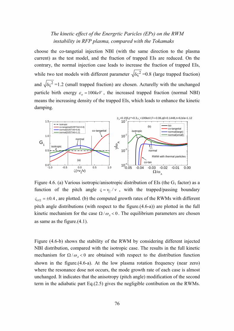
The kinetic effect of the Energrtic Paricles (EPs) on the RWM instability in RFP plasma, compared with the Tokamaks
76
choose the co-tangetial injection NBI (with the same direction to the plasma current) as the test model, and the fraction of trapped EIs are reduced. On the contrary, the normal injection case leads to increase the fraction of trapped EIs,
while two test models with different parameter 2 =0.8 (large trapped fraction)
and 2 =1.2 (small trapped fraction) are chosen. Acturelly with the unchanged
particle birth energy 100keV , the increased trapped fraction (normal NBI)
means the increasing density of the trapped EIs, which leads to enhance the kinetic damping.
-1.0 -0.5 0.0 0.5 1.00.0
0.5
1.0
1.5 isotropic co-tangetial(DZETA0=0.8) normal(DZETA0=0.8) normal(DZETA0=1.2)
G1
(=v||/v)
co-tangetial
normal
isotropic
(a)
-0.05 -0.04 -0.03 -0.02 -0.01 0.0010-4
10-3
10-2
10-1
P=0.155,*=0.3,
=100keV,F=-0.06,q0=0.1448,n=6,b/a=1.12
iso co-tangetial normal(large) normal(small)
/
A
isotropic
co-tan
normal
RWM with thermal particles
(b)
Figure 4.6. (a) Various isotropic/anisotropic distribution of EIs (the G1 factor) as a
function of the pitch angle ||v / v , with the trapped/passing boundary
0 4s . , are plotted. (b) the computed growth rates of the RWMs with different
pitch angle distributions (with respect to the figure.(4.6-a)) are plotted in the full
kinetic mechanism for the case / 0A . The equilibrium parameters are chosen
as same as the figure.(4.1).
Figure (4.6-b) shows the stability of the RWM by considering different injected NBI distribution, compared with the isotropic case. The results in the full kinetic
mechanism for / 0A are obtained with respect to the distribution function
shown in the figure.(4.6-a). At the low plasma rotation frequency (near zero) where the resonance dose not occurs, the mode growth rate of each case is almost unchanged. It indicates that the anisotropy (pitch angle) modification of the second term in the adiabatic part Eq.(2.5) gives the negligible contibution on the RWMs.
The kinetic effect of the Energrtic Paricles (EPs) on the RWM instability in RFP plasma, compared with the Tokamaks
77
For the co-tangetial NBI case, we find that the rotation frequency required to stabilize the mode is slightly reduced with respect to isotropic case, because the cancellation between two spesies is reduced due to the reduced kinetic contribution from the EIs. For the normal NBI case, the stability of the RWM will not be achieved due to the enhanced kinetic cancellation (dominated by the transit resonance of the thermal ions) by considering the small trapped fraction with
2 =1.2. However, the mode can be stabilized again if the fraction of the EIs
becoming large sufficiently, where the kinetic damping is dominated by the EIs. And the critical rotation frequency, which is smaller than the isotropic case, is obversed. As the results, the anisotropy effect of the EIs leads to a significant influence on the RWM stability in the full kinetic mechanism, and even changes the stabilizing mechanism (the dominated kinetic damping) in the RFP plasma.
4.3 Kinetic effects of EPs with isotropic distribution on RWMs inTokamakplasma
With the aim of comparsion with the case in the RFP plasma, the kinetic effect of the EIs with the isotropic distrubution is studied in the tokamak plasma. The parameters similar to the RFP case are chosen as b/a=1.12, BT=1.5T, a/R=0.2295.
The total plasma beta 0.011 ( 3.0N ) is also near the ideal beta limit
0.012 ( 3.2N ), where the kinetic effect becomes significant due to the small
plasma energy bW . In this work, only precession kinetic mechanism provided by
the trapped particles is considered, because it is the dominated kinetic effect of both the thermal particles and EIs in the Tokamak plasma. As shown in the
figure.(4.7), the n=1 mode growth rate versus the plasma rotation frequency / A
are plotted for each species types with the birth energy 100keV and the
pressure fraction 2 8/ (1 )Pa Pth s . It is found that the RWMs can be stabilized by
the precession resonance of the EIs alone at / 0.026A (opposite direction),
resulting in the same kinetic characteristic of the EIs compared to the RFP case. The results are different from that by considering the precession kinetic damping of the thermal particles alone, where the stability of the RWM is achieved at the
low plasma rotation frequency / ~ [ 0.0025,0.009]A , as observed in the
previous work. Furthermore by considering the kinetic effect of the two species together, we find that the stability region at the low rotation frequency

The kinetic effect of the Energrtic Paricles (EPs) on the RWM instability in RFP plasma, compared with the Tokamaks
78
/ ~ [ 0.0025,0.003]A is reduced, particularly in the positive direction. It
indicates that the slight cancellation between two species exists, and the thermal precession damping is still dominated. For the EIs dominated region
/ 0.02 ~ 0.04A , the conbined precession kinetic effect plays a role of
destabilization of the mode, which leads to increase the critical rotation frequency
/C A compared with the EIs alone case.
-0.05 -0.04 -0.03 -0.02 -0.01 0.00 0.01 0.02 0.03 0.04 0.0510-5
10-4
10-3
10-2
10-1
/
A
/A
precession_th precession_hot precession_th+hot
Tokamak, Ea=100keV, =0.011, b/a=1.12, Pa/Pth(s)=1.0(1-s2)8
Figure 4.7. The n=1 RWM growth rate / A versus the plasma rotation frequency
/ A in tokamak plasma are plotted, with the comparision of precession
resonance for different particle species types, including (a) the thermal particles (black line), (b) the EIs (red line) and (c) the case with combined species (blue
line). The birth energy of EIs is 100keV , and the pressure fraction of EIs is 2 8/ (1 )Pa Pth s with the beta ratio * 0.19 .
Figure.(4.8) shows (a) the real part and (b) the imaginary part of kinetic energy
componants imkW for each species as well as the total imaginary kinetic energy of
both species. It shows that the imaginary kinetic energy contributed by the EIs
obtains its maximum value at / ~ 0.005A . However, by considering the kinetic
energy from EIs alone, the mode can not be stabilized because of the large
destabilizing term ( 0)bW W in Eq.(4.2) at the small rotation frequency. The
stability of the RWMs can be easier achieved by increasing the rotation frequency, where the kinetic damping becomes larger and the destabilizing term

The kinetic effect of the Energrtic Paricles (EPs) on the RWM instability in RFP plasma, compared with the Tokamaks
79
( 0)bW W in Eq.(4.2) becomes relatively smaller. The obtained behavior of the
EIs in tokamak case is a little different from the RFP case, where the precession resonance of EIs does not occurs in the positive direction.
In the combined kinetic mechanism, for the case / 0A , we find that the
dominated kinetic damping is from the precession resonance of the electrons at low plasma rotation. The contribution from the EIs gives a slight cancellation
effect, resulting in that the stability region is reduced. For the case / 0A , it is
interesting find that the dominated stabilized kinetic contribution from the ions is enhanced by that from the EIs at low rotation frequency. However, the increased kinetic value does not lead to increase the stability region in the opposite direction. This is because the precession contribution of the EIs is not large sufficiently,
which makes the results not as obvious as the / 0A case. Moreover, in the
high rotation region, the precession of the EIs is dominated. Without the kinetic contribution from the transit resonance, the stabilization of the RWM is reduced. The increased critical rotation frequency, compared with the EIs alone case, is probably due to the cancellation of the real kinetic energy components, which
leads to reduce the stabilizing term ( ) 0rek bW W W in Eq.(4.2), as shown in
the figure.(4.8-a), where 0rekW and ( ) 0bW W . Some preliminary results
also show that with the transit resonance of the passing ions, which leads to cancel the imagnery kinetic energy contributed by EIs, the RWMs are destabilized. Thus the further studies on this part are necessary in the future reseach.
-0.05 -0.04 -0.03 -0.02 -0.01 0.00 0.01 0.02 0.03 0.04 0.05-0.0500
-0.0375
-0.0250
-0.0125
0.0000
0.0125
0.0250
Tokamak, Ea=100keV, =0.011, b/a=1.12, Pa/Pth(s)=1.0(1-s2)8
precession_ion precession_electron precession_hot total
Wk_
real
/A
(a)
-0.05 -0.04 -0.03 -0.02 -0.01 0.00 0.01 0.02 0.03 0.04 0.05-0.03
-0.02
-0.01
0.00
0.01
0.02
0.03Tokamak, Ea=100keV, =0.011, b/a=1.12, Pa/Pth(s)=1.0(1-s2)8
Wk_
ima
g
/A
precession_ion precession_electron precession_hot total
(b)
Figure 4.8. The (a) real and (b) imaginary parts of the kinetic energy imkW ,
including the kinetic components of each species and the total kinetic energy of

The kinetic effect of the Energrtic Paricles (EPs) on the RWM instability in RFP plasma, compared with the Tokamaks
80
both species conbined in both direction: (a) / 0A and (b) / 0A , are
plotted as the function of the rotation frequency, with the parameters same as figure.(4.7).
In the figure.(4.9), the radial profiles of the averaged precession frequency of the
trapped thermal ions and electrons as well as the EIs with 100keV are plotted
in the tokamak plasma. We find that it is much smaller than the RFP case due to the smaller scale lengths of the magnetic curvature and gradient in the tokamak case. The precession frequency of the EIs is comparible (near zero) to that of the trapped thermal particles in the region of s=0.4~0.6. Furthermore, in the region near the plasma core (s=0.0~0.2), the precession frequency is picked rapidly. Figure.(4.10) shows the precession frequency of the EIs, which is the 2-D plot in the R-Z plane. The value of the precession frequency changes the sign from the low field side to the high field side, and the region in which the frequency is negative, is much larger than the RFP case. It leads to make the resonance
happened when / 0A , particularly in the blue region as shown in the
figure.(4.10). On the contrary for the case / 0A , the precession resonance of
the EIs is completely from the yellow region which is very similar to that in the RFP plasma.
0.0 0.2 0.4 0.6 0.8 1.0-0.02
0.00
0.02
0.04
0.06
0.08
0.10
0.12Tokamak, Ea=100keV, =0.011, *=1.0(1-s2)8
<
d>
/A
s
di
de
da
Figure 4.9. The radial profiles of various frequencies of each species in the tokamak plasma, over the velocity space and over the poloidal angle, are plotted
including the precession frequency ,di de of the thermal trapped ions and the
electrons, as well as the precession frequency d of the trapped EIs with their
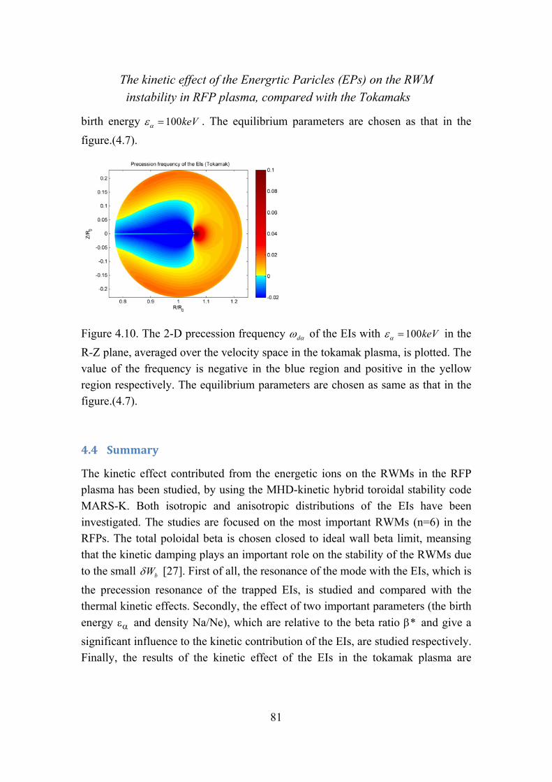
The kinetic effect of the Energrtic Paricles (EPs) on the RWM instability in RFP plasma, compared with the Tokamaks
81
birth energy 100keV . The equilibrium parameters are chosen as that in the
figure.(4.7).
Figure 4.10. The 2-D precession frequency d of the EIs with 100keV in the
R-Z plane, averaged over the velocity space in the tokamak plasma, is plotted. The value of the frequency is negative in the blue region and positive in the yellow region respectively. The equilibrium parameters are chosen as same as that in the figure.(4.7).
4.4 Summary
The kinetic effect contributed from the energetic ions on the RWMs in the RFP plasma has been studied, by using the MHD-kinetic hybrid toroidal stability code MARS-K. Both isotropic and anisotropic distributions of the EIs have been investigated. The studies are focused on the most important RWMs (n=6) in the RFPs. The total poloidal beta is chosen closed to ideal wall beta limit, meansing that the kinetic damping plays an important role on the stability of the RWMs due
to the small bW [27]. First of all, the resonance of the mode with the EIs, which is
the precession resonance of the trapped EIs, is studied and compared with the thermal kinetic effects. Secondly, the effect of two important parameters (the birth
energy and density Na/Ne), which are relative to the beta ratio * and give a
significant influence to the kinetic contribution of the EIs, are studied respectively. Finally, the results of the kinetic effect of the EIs in the tokamak plasma are

The kinetic effect of the Energrtic Paricles (EPs) on the RWM instability in RFP plasma, compared with the Tokamaks
82
obtained, in order to compare to the RFP case and make more physical understanding.
The stability of the RWMs due to the kinetic effect of the EIs alone has been observed in the RFP plasma, which has the similar kinetic damping to that from the thermal particles (dominated by the ion acoustic Landau damping of the thermal passing ions). The precession resonance of the trapped EIs can occur only
in the nagative direction / 0A (opposite to the direction of plasma current),
and the critical rotation frequency with the birth energy of the EIs 100keV is
comparible to the thermal particles. By considering the full kinetic mechanism, the cancellation between two species is found, which leads to enlarge the critical rotation frequency required to stabilize the mode. The effect of the equilibrium parameter of the EIs gives the more detail results as shown in the following: (a)
The birth energy leads to decide the precession frequency, resulting in
determine the resonance region due to the resonance condition 0d ; (b) The
density of the EIs, which is analysed through the anisotropic distribution study, is roughly proportional to the kinetic contribution (relative to the pressure of the trapped EIs). As the results, it leads to give directly the influence to the cancellation between two species, and the kinetic contribution from the EIs can be dominated if the fraction of the trapped EIs is sufficiently large.
A comparion of the kinetic effect of the EIs in the tokamak configuration with the RFP case has also been investigated. The most difference between two fusion devices is their magnetic configuration, which leads to the different distribution of the EIs precession frequency. As the results, the precession frequency of EIs is
much smaller in the most region of plasma ( ~ 0d ) than the RFP case. The
precession resonance of trapped EIs becomes significant at the low plasma rotation
in both direction (a) / 0A and (b) / 0A . However, the stabilization of the
RWMs is difficultly achieved at the low rotation frequency by the EIs alone, because the kinetic damping of the EIs is not large sufficiently. Furthermore, the similar behavior of the EIs, compared with the RFP case, is found by increasing
the plasma rotation frequency ( / 0A ), because of the increased stabilizing
kinetic damping from the EIs relatively.
The kinetic effect of the Energrtic Paricles (EPs) on the RWM instability in RFP plasma, compared with the Tokamaks
83
The analysis in this work shows the slight cancellation of kinetic effect between the dominated thermal kinetic damping and the precession resonance of the EIs in the both configurations. However, with the presence of the EPs in the plasma, the condition of the stabilization of RWMs by kinetic damping depends on the parameters of the two species. Appropriately choosing the NBI parameters (energy, pitch angle of injection et al) may possibly minimize the cancellation effects.


The Excitation of the Fishbone-Like External Mode in both RFP and Tokamak configurations
85
Equation Chapter (Next) Section 1
Chapter 5
5 TheExcitationoftheFishbone‐LikeExternalModeinbothRFPandTokamakconfigurationsThe energetic particle physics is an important issue to be studied in order to understand the behavior of the burning plasmas which represents the primary scientific challenge faced by ITER and fusion research in general. The self-heating is provided by the alphas generated at 3.5MeV by the D–T fusion reactions. In addition, other fast or energetic ions with energies well above the thermal distribution of the plasma bulk, are generated by neutral beam injection (NBI) and ion cyclotron resonant heating (ICRH). These are expected to play major role in achieving optimal burning plasma scenarios with external heating and/or current drive [55]. The Energetic Particles (EPs) may interact with the bulk plasma waves and instabilities, which possibly lead to destabilize/stabilize the existing turbulence in the bulk plasma, such as the RWMs in the previous studies.
The EPs even leads to excite a new type of instabilities, which may result to redistribution and losses of EPs. It has been observed and studied in many experimental and theoretical investigations for Tokamak configurations, such as JT-60U, DIII-D et al, by considering the energetic ions (EIs) from the NBI injection [66, 67, 68, 59, 7, 8, 69, 70, 71, 72, 73]. It is found that this bursting
mode can appear when the beta fraction of the EPs *h / (the fraction of the
EPs beta to the total plasma beta) exceeds a certain critical value * *C [2-5].
With the presence of the EPs, this bursting mode can coexist with the RWMs at the same time. The instability driven by the EPs is also been found in the Reversed Field Pinch (RFP) plasma (MST) [10,74], which is called energetic particle mode (EPM). However, the characteristic of this observed EPMs have not been

The Excitation of the Fishbone-Like External Mode in both RFP and Tokamak configurations
86
understood clearly, due to the few NBI experiments in the RFP devices. In this thesis, this bursting mode, which is called the Fishbone-Like External kink Mode (FLEM) here, is investigated in RFP plasma, by the kinetic-MHD hybrid toroidal code MARS-K. The comparison with the tokamak is also investigated. The nature and the physics of the FLEM are clarified by numerical analysis.
Section 5.1 investigates the physical understanding of the FLEM with the isotropic EIs in the RFP plasma. The effects of various equilibrium parameters, including the plasma pressure and the wall position as well as the birth energy and the density of the EPs, are also investigated. In the section 5.2, the studies of the FLEMs in the tokamak is carried out, and compared with the RFP case. It is found that the FLEM in the tokamaks has the similar nature to that in the RFP plasma. The conclusion and the discussion are given in the section 5.3.
5.1 KineticeffectsofEPswith isotropicdistributiononFLEMs inRFPplasma
5.1.1 Physicalunderstanding
In this work, another instabilizing branch has been found by considering the kinetic effect of the EIs in the RFP plasma. Compared with the RWM branch, it has the similar mode characteristic that the resonance surface of the mode is located outside the plasma, in particular the studies in the present work focus on the n=6 mode with the safety factor at the plasma center q(0)=0.1448 < -m/n=1/6 (internally non-resonance mode). The instability is driven unstable by the precessional drift resonance of the EIs, even with the ideal conducting wall. It is also interesting to note that, contrary to the RWM, FLEMs satisfy the usual external ideal kink dispersion relation. Overall, the new instability is so called non-resonant fishbone-like external kink mode (FLEM), which is distinguish with the RWM instabilities in the RFP plasma.
In order to understanding physically how the FLEM is triggered by the precession resonance of the EIs, the usual external ideal kink dispersion relation, which is relevant to the energy analysis, is considered and written by,
0F vb kI W W W (5.1)

The Excitation of the Fishbone-Like External Mode in both RFP and Tokamak configurations
87
where I represents the inertial energy component. The normalized dispersion
relation can be further written separately under the approximation r , as
observed in the figure. (5.1),
2 r r r r rr F vb k b k bkn W W W W W W (5.2-a)
2 i ir k Fn W W (5.2-b)
Where the superscript “r” denotes the real part of the energy components and the superscript “i” denotes the imaginary part. The potential energy components are
normalized by the plasma inertia. Numerical analysis found that rbW is usually
the dominant contributor to r r rbk b kW W W in Eq. (5.2-a), and that i i
k FW W
in Eq. (5.2-b). The further approximation leads to the reduced dispersion relation,
rr bn W (5.3-a)
2
ik
r
W
n
(5.3-b)
Eq. (5.3-a) and (5.3-b) clearly indicates the FLEM physics: The mode frequency is
mostly determined by the real part of the energy component rbW , and the growth
rate of the instability is mainly determined by ikW , which comes from the
precession drift resonance of energetic ions.
Usually, the total plasma pressure and wall position largely affects bW , and hence
the real frequency r . If the frequency r falls inside the range satisfying the
resonant condition with the precession frequency of a given type of EPs, the
instability of FLEM can appear. The value of ikW is mainly determined by the
two features of EIs: 1) the density fraction of EIs a total a en / n n / n , and 2) the
birth energy , which directly links to the precession frequency d . The
analysises with the detailed numerical results are described in the following
sections. The parameter of the beta ratio thermal* / ( P thermal )
reflects the combination of these two effects. Where and thermal denotes the

The Excitation of the Fishbone-Like External Mode in both RFP and Tokamak configurations
88
poloidal beta (2
0
8P totP V
I R
) of the EIs and the thermal particles respectively.
In the figure.(5.1), the typical results of the n=6 FLEM are plotted with the
poloidal beta 0 135p . , the wall position b/a=1.12, the reversal parameter F=-
0.06 ( ( )/F B a B ), the aspect ratio 0 2295a / R . and q(0)=0.1448. It
compares the normalized growth rates and real frequencies of FLEMs directly computed by MARS-K, with that calculated by using the dispersion relation Eq. (5.3). Two cases, with and without plasma rotation, are investigated. It is found that the results in different numerical mechanism are agreed well with each other.
0.0 0.5 1.0 1.5 2.00.00
0.01
0.02
0.03
0.04
0.05
0.06
P=0.135,
=100keV,F=-0.06,q0=0.1448,b/a=1.12,n=6
FLM without thermal particles
/A=0.00,Code
/A=0.00,Dispersion
/A=0.05,Code
/A=0.05,Dispersion
/
A
*
(a)
0.0 0.5 1.0 1.5 2.00.0
0.2
0.4
0.6
0.8
P=0.135,
=100keV,F=-0.06,q0=0.1448,b/a=1.12,n=6
FLM without thermal particles
/A=0.00,Code, /
A=0.00,Dispersion
/A=0.05,Code, /
A=0.05,Dispersion
r/
A
*
(b)

The Excitation of the Fishbone-Like External Mode in both RFP and Tokamak configurations
89
Figure 5.1. Comparison of the normalized (a) growth rates A/ and (b) real
frequencies r A/ of FLEM as a function of the energetic particle beta fractions
thermal* / ( P thermal ), between the direct MARS-K computations
and that calculated by using the dispersion relation Eq.(5.3). The equilibrium
parameters are chosen as: the poloidal beta 0 135p . , the wall position b/a=1.12,
the reversal parameter F=-0.06, the aspect ratio 0 2295a / R . and q(0)=0.1448.
5.1.2 ThecharacteristicoftheFLEMintheRFPplasma
In this study, the characteristic of the non-resonance FLEM in the RFP plasma is studied by using the parameters of the RFX-mod experiment, including the aspect
ratio 0 2295a / R . and the safety factor at the plasma center q(0)=0.1448. The
electron density at the plasma core is chosen as 19 30 2 5 10en . / m . For energetic
ions, only the precession resonance of the trapped EIs is considered. The bounce and transit frequencies of the EIs are much higher than that of thermal ions and the precession frequency of EIs, and their kinetic contributions will be neglected. The comparison of the kinetic effect contributed by the EIs with that of the thermal particles, which takes into account the precession motion of both the trapped ions and the electrons, the bounce motion of the trapped ions, and the circulating (transit resonance) of the passing ions, is also investigated as shown in the figure.(5.2). The kinetic mechanism of both thermal particles and EIs is so call full kinetic mechanism. The pressure of the EIs is given by the pressure fraction
2 80(1 )*
a thP / P s s , as the example shown in the figure.(2.2) we have 0 1 0* .
and 0 176* . .
In the figure.(5.2), we plot the n=6 FLEM (a) growth rate A/ and (b) real
frequency r A/ (normalized by the Alfven frequency at the magnetic axis A )
versus the poloidal plasma beta P for three case, which are calculated in the
kinetic mechanism of EIs alone with 0 0 3* . ( 0 062* . ) and 0 1 0* .
( 0 176* . ), as well as the full kinetic with 0 1 0* . ( 0 176* . ). The other
equilibrium parameters are b/a=1.12, F=-0.06, q0=0.1448, and no plasma rotation

The Excitation of the Fishbone-Like External Mode in both RFP and Tokamak configurations
90
is considered. The birth energy of the EIs is kept by 100keV , which indicates
that larger fraction 0* ( * ) leads to larger density of the EIs. It is found that the
FLEM instabilities can be triggered when the poloidal plasma beta P is
exceeding a critical value, if the kinetic effect of the EIs is taken into account in the MHD model. Compared with the real frequency of the RWMs, the FLEM has very large real frequency, even without the plasma rotation, which is reduced by increasing the poloidal beta. It is also observed that the mode instability is reduced by considering the smaller EIs fraction or the full kinetic mechanism. These results confirm that the FLEM in the RFP plasma is driven by the EIs kinetic contribution, and the thermal pariticles gives a stabilizing effect on the FLEM. Similar to the RWMs in the previous results, the cancellation of the kinetic effect between two
species exists. By further increasing the poloidal beta P , the FLEM instability
converts to the ideal kink mode, and the real frequency of the ideal kink mode keeps small. The ideal wall beta limit is modified by the kinetic effect
( limit 0 162P _ . for EIs alone and limit 0 182P _ . for full kientic), compared
with the fuild case ( limit 0 159P _ . ).
0.08 0.10 0.12 0.14 0.16 0.1810-4
10-3
10-2
10-1
100b/a=1.125,Ea=100keV,F=-0.06,q0=0.1448
hot1,*0=0.3
hot2,*0=1.0
th+hot,*0=1.0
/
A
P
P
hot=0.162
P
fluid=0.159
P
th+hot=0.182
(a)
0.08 0.10 0.12 0.14 0.16 0.180.0
0.2
0.4
0.6b/a=1.125,Ea=100keV,F=-0.06,q0=0.1448
hot1,*0=0.3
hot2,*0=1.0
th+hot,*0=1.0
r/
A
P
P
hot=0.162 P
th+hot=0.182
P
fluid=0.159
(b)
Figure 5.2. The n=6 FLEM (a) growth rate A/ and (b) real frequency r A/
(normalized by the Alfven frequency at the magnetic axis A ) versus the poloidal
plasma beta P are plotted in the kinetic mechanism of EIs alone with 0 0 3* .
( 0 062* . ) and 0 1 0* . ( 0 176* . ), as well as the full kinetic with 0 1 0* .

The Excitation of the Fishbone-Like External Mode in both RFP and Tokamak configurations
91
( 0 176* . ). The other equilibrium parameters are b/a=1.12, F=-0.06, q0=0.1448.
No plasma rotation is considered and the birth energy of the EIs is kept by
100keV .
0.0 0.2 0.4 0.6 0.8 1.00.0
0.1
0.2
0.3
0.4
0.5
0.6
r=0.525
r=0.332
r=0.182
b/a=1.125,*0=0.3,
a=100keV,F=-0.06,q0=0.1448
(m-nq)p, n
da,
P=0.16
(m-nq)p, n
da,
P=0.14
(m-nq)p, n
da,
P=0.115
<
>/
A
s
Figure 5.3. The radial profiles of various frequencies of each species over the velocity space and over the poloidal angle are plotted, including the transit
frequency ( ) pm nq of the thermal passing ions and the precession frequency of
the trapped EIs dn with different poloidal beta 0 115 0 14 0 16P . , . , . . The FLEM
real frequency 0 525 0 332 0 182r A/ . , . , . with respect to P are also plotted, in
which shows the resonance region of the FLEM (shadow region). The equilibrium parameters are chosen as same as that in the figure.(5.2).
As shown in the figure.(5.3), we plot the radial profile of each frequencies averaged over the velocity space and the poloidal angle. The dominated resonance frequencies are included for each species, which are the transit frequency of the
thermal passing ions pm nq and the precession frequency of the trapped EIs
dn . Three cases with different poloidal beta 0 115 0 14 0 16P . , . , . are considered,
and the FLEM real frequency 0 525 0 332 0 182r A/ . , . , . are also plotted, in
which shows the resonance region (shadow region in the figure.(5.3)) clearly. Different from the RWMs, the resonance for FLEMs occurs under the condition of

The Excitation of the Fishbone-Like External Mode in both RFP and Tokamak configurations
92
d rn n as shown in the resonance oparetor Eq.(2.10), which can be
satisfied even at 0 , i.e. when d rn , since r is directly related to rbW
and can be rather high. For RWMs, on the other hand, the resonance contribution
to ikW by the EPs precession motion requires the condition of 0d , due to
the small mode real frequency 0r . It is found that the FLEM real frequency
increases by reducing the poloidal beta P , which becomes far away from the
precession frequency of the EIs. This makes the mode resonance occur difficultly, and finally the FLEM becomes stable due to the neglected kinetic driven contribution from the EIs. When the kinetic effect of the thermal particles is considered, in particular the kinetic effect of the thermal passing ions, it is found
that its frequency region pm nq is similar to dn . It indicates that the
cancellation of the kinetic effect between each species for the FLEM occurs.
Figure.(5.4) shows the energy components as described in the dispersion relation
in Eq.(5.3) with 0 1 0* . ( 0 176* . ), by considering (a) the kinetic effect of EIs
alone and (b) the full kinetic effect. The detailed kinetic energy kW components
in the figure.(5.4-b) are plotted in the figure.(5.5), including (a) the real part and (b)
the imaginary part of the kinetic energy ikW . It is found that by reducing the
poloidal beta P , the total potential plasma energy rbW in the fuild theory is
increased as shown in the figure.(5.4-a) and (5.4-b). This is because of the reduced
pressure driven energy PW , which has negative value in Eq.(2.11), while the
other potential energy keep almost unchanged. It is also observed that the
imaginary part of the kinetic energy ikW becomes neglected at the critical
poloidal beta P , which leads to the zero growth rate of the FLEM as described in
Eq.(5.3-b). For the case (a) with the EIs kinetic effect alone, by considering the dispersion relation in Eq.(5.3-a), it is explained that the real frequency of the
FLEM becomes large with the reduced poloidal beta P , which leads to the
disappear of the precessional drift resonance of the trapped EIs as studied previously. For the case (b) with the full kinetic effect, on the other side, the
neglected imarginary kinetic energy ikW is mainly due to cancellation contributed
from the thermal particles. Here the mode resonance with the precession motion of

The Excitation of the Fishbone-Like External Mode in both RFP and Tokamak configurations
93
the EIs still exists, and the kinetic energy contributed from the EIs is significant enough to drive the FLEM instability as shown in the figure.(5.5-b). As the results, the kinetic contribution of the thermal particle leads to stabilize the FLEM instability.
0.10 0.12 0.14 0.16 0.18 0.20-0.3
-0.2
-0.1
0.0
0.1
0.2
0.3
0.4b/a=1.125,Ea=100keV,F=-0.06,q0=0.1448
W/
W2
P (*
0=1.0, hot)
dWK_real dWK_imag dWb dWb+dWk_real
(a)
0.10 0.12 0.14 0.16 0.18 0.20-0.3
-0.2
-0.1
0.0
0.1
0.2
0.3
0.4b/a=1.125,Ea=100keV,F=-0.06,q0=0.1448
W/
W2
P (*
0=1.0, th+hot)
dWK_real dWK_imag dWb dWb+dWk_real
(b)
Figure 5.4. The energy components as described in the dispersion relation in
Eq.(5.3) versus the poloidal plasma beta P are plotted with 0 1 0* . ( 0 176* . ),
by considering (a) the kinetic effect of EIs alone and (b) the full kinetic effect. The other parameters are same as that in the figure.(5.2).
0.10 0.12 0.14 0.16 0.18 0.20
-0.15
-0.10
-0.05
0.00
0.05
0.10
0.15
0.20
0.25b/a=1.125,Ea=100keV,F=-0.06,q0=0.1448
real
_W
k/W
2
P (*
0=1.0, th+hot)
thermal hot full
(a)
0.10 0.12 0.14 0.16 0.18 0.20-0.3
-0.2
-0.1
0.0
0.1
0.2
0.3b/a=1.125,Ea=100keV,F=-0.06,q0=0.1448
imag
_W
k/W
2
P (*
0=1.0, th+hot)
thermal hot full
(b)
Figure 5.5. The detailed kinetic energy components kW in the figure.(5.4-b)
versus the poloidal plasma beta P are plotted with 0 1 0* . ( 0 176* . ),

The Excitation of the Fishbone-Like External Mode in both RFP and Tokamak configurations
94
including (a) the real part rkW and (b) the imaginary part i
kW of the kinetic
energy. The other parameters are same as that in the figure.(5.2).
The ideal wall beta limit predicted in the fuild theory for both cases in the
figure.(5.4) are same, where the condition 0 0rbW . is satisfied and the beta limit
is limit 0 158P _ . . It is found that the real part of the kinetic energy rkW leads
to modify this beta limit in the fuild theory with the condition 0 0rbkW . . For the
EIs alone case, the modified beta limit limit 0 162P _ . is increased slightly due
to the positive value of the real kinetic energy rkW . For the full kinetic case, the
enhanced real part of the kinetic energy rkW , as shown in the figure.(5.5-a), leads
to the larger beta limit limit 0 182P _ . . The FLEM instability converts to the
ideal kink instability at the beta limit limitP _ . The detail analysis above the beta
limit is not carried out in this work, because we take care more about the performance under the ideal wall beta limit in the real device.
In the figure.(5.6-a), the particle phase space averaged precession frequency of the
trapped EIs is plotted with the poloidal beta 0 14P . and the beta ratio 0 0 3* .
( 0 062* . ) in the R-Z plana. The imaginary part of the kinetic energy component
contributed by the EIs precessional drift resonance is also plotted in the toroidal cross section as shown in the figure.(5.6-b), corresponding to the figure.(5.6-a).
The FLEM frequency calculated with the above parameter is 0 332r A/ . . It is
found that the precession frequency stay in a large region (yellow region) with its
amplitude 0 2dn ~ . (n=6). The precession frequency has very large positive
value in a small region near the plasma core. The imaginary kinetic energy ikW
has the maximum amplitude near the plasma core. It is different from the RWMs due to the different distribution of the EIs and the particular resonance mechanism
of the FLEM. The asymmetry distribution of ikW is because of the dominated
contribution from the m=-1 harmonic, which has large amplitude in this region similar to the RWMs.

The Excitation of the Fishbone-Like External Mode in both RFP and Tokamak configurations
95
( a ) ( b )
Figure 5.6. The 2-D plots of (a) the precession frequency of the EIs dn
(averaged over the velocity space), and (b) the imaginary parts of the kinetic
energy ikW for the FLEM with the poloidal beta 0 14P . and 0 0 3* .
( 0 062* . ), in the R-Z plane. The other equilibrium parameters are chosen as the
previous description.
As shown in the figure.(5.7), we plot the n=6 FLEM (a) growth rate A/ and (b)
real frequency r A/ versus the wall position b/a with the kinetic effect of the
EIs alone, for two different poloidal beta 0 135P . and 0 1P . . The other
equilibrium parameters are F=-0.06, q0=0.1448, and no plasma rotation is considered. The results shown in the figure are below the ideal wall beta limit. Similar to the previous result in the figure.(5.2), the FLEM can be triggered if the wall position exceeds a critical value, and the instability becomes more significant by setting the wall farther away from the plasma. The neglected FLEM instability at the critical wall position is due to the increased mode frequency by reducing the wall position b/a, where the mode resonance with the precessional motion of the
trapped EIs does not occur. Here the increased vaccum energy Wvb (>0) by decreasing the wall position b/a leads to increase the total plasma potential energy
rbW (>0), which indeed increases the real frequency of the FLEM by considering
the dispersion relation in Eq.(5.3-a). Furthermore, as an example with the
parameter 0 0 5* . and 100keV in the figure.(5.7), the trigger of the FLEM

The Excitation of the Fishbone-Like External Mode in both RFP and Tokamak configurations
96
for the lower poloidal beta 0 1P . (blue line) case requires farther wall position
b/a compared with the higher 0 135P . case (red line). It is explained that the
increased rbW due to the reduced pW (<0) needs to be compensated by the
increased Wvb (>0). As the result, the plasma equilibrium parameters, the wall position b/a and the total plasma pressure P, brings a significant effect on the FLEM.
For each P case in the figure.(5.7), the comparison of the FLEMs with different
equilibrium parameter 0* and of the EIs is also investigated. Firstly, it is found
that the FLEM is independent on the penetration time of the wall, and the FLEM with the resistive wall (black line) and with ideal conducting wall (black points)
has almost same eigenvalue. This is due to the very high frequency r A/ of the
ELEM, where the resistive wall plays the role of the shielding action similar to the ideal conducting wall. Secondly, we find that the increased density of EIs leads to enhance the FLEM instability, where the critical wall position b/a is slightly
reduced, as the example for the case 0 135P . with 0 0 3* . (black line),
0 0 5* . (red line), 0 2 0* . (green line) by keeping 100keV . The density of
the EIs for each 0 is 0 15en / n . , 0 22en / n . , 0 46en / n . , which leads to
increase the kinetic driven ikW due to Eq.(2.12). However, this influence of the
density on the FLEM is not important compared with that of the equilibuim
parameters b/a and P , where the density of EIs increases almost three times with
the change of the critical wall position 0 0625cb / a . . Finally, we compare the
FLEMs with different birth energy by keeping 0 0 5* . unchanged for both
cases. It is found that the increased 150keV (red dashed-dot line for
0 135P . case and blue dashed-dot line for 0 1P . case) leads to increase the
FLEM instability significantly. The FLEM can be unstable, even with the wall that
is almost closed to the plasma, as the example with 0 0 5* . and 200keV
(yellow dashed-dot line) for 0 1P . case. This is because of the increased
precession frequency of the EIs dn , which makes the mode resonance
happening easily for a given plasma equilibrium. The resonance condition

The Excitation of the Fishbone-Like External Mode in both RFP and Tokamak configurations
97
d rn ( 0 ) can be satisfied, with higher rbW which determines the higher
FLEM real frequency r in Eq.(5.3-a). Consequently, the birth energy of the EIs
, as well as the wall position b/a and the total plasma pressure P ( P ), gives the
dominated effect on the characteristic of the FLEM instability.
1.00 1.05 1.10 1.15 1.20 1.250.00
0.04
0.08
0.12
0.16
0.20
hot only
*0=0.5,Ea=100keV
*0=0.5,Ea=150keV
*0=0.5,Ea=200keV
P=0.1
/
A
b/a
*0=0.3,Ea=100keV
*0=0.3,Ea=100keV,ideal wall
*0=0.5,Ea=100keV
*0=0.5,Ea=150keV
*0=2.0,Ea=100keV
P=0.135
(a)
1.00 1.05 1.10 1.15 1.20 1.250.0
0.3
0.6
0.9
*0=0.3,Ea=100keV
*0=0.3,Ea=100keV,ideal wall
*0=0.5,Ea=100keV
*0=0.5,Ea=150keV
*0=2.0,Ea=100keV
P=0.135
*0=0.5,Ea=100keV
*0=0.5,Ea=150keV
*0=0.5,Ea=200keV
P=0.1
hot only
r/
A
b/a
(b)
Figure 5.7. The n=6 FLEM (a) growth rate A/ and (b) real frequency r A/
versus the wall position b/a with the kinetic effect of the EIs alone, for two
different poloidal beta 0 135P . and 0 1P . . For each P case, the
comparison of the FLEMs with different equilibrium parameter 0* and of the
EIs is also investigated. For 0 135P . case, (a) 0 0 3* . (black solid line),
0 0 5* . (red solid line), 0 2 0* . (green solid line) with 100keV ; (b) 0 0 3* .
and 100keV with ideal conducting wall (black points); (c) 0 0 3* . with
150keV (red dashed line). For 0 1P . case, 100keV (blue solid line),
150keV (blue dashed-dot line) and 200keV (yellow dashed-dot line) are
chosen while keeping 0 0 5* . . The other equilibrium parameters are F=-0.06,
q0=0.1448, and no plasma rotation is considered.
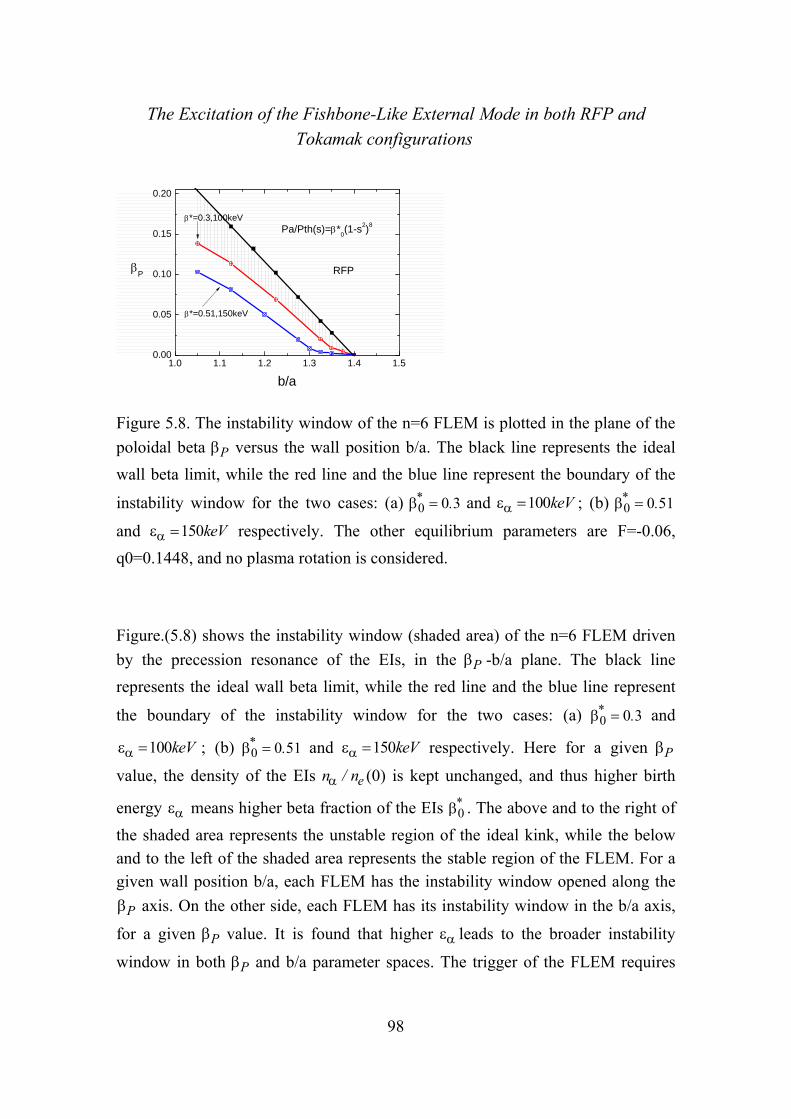
The Excitation of the Fishbone-Like External Mode in both RFP and Tokamak configurations
98
1.0 1.1 1.2 1.3 1.4 1.50.00
0.05
0.10
0.15
0.20
*=0.51,150keV
Pa/Pth(s)=*0(1-s2)8
*=0.3,100keV
P
b/a
RFP
Figure 5.8. The instability window of the n=6 FLEM is plotted in the plane of the
poloidal beta P versus the wall position b/a. The black line represents the ideal
wall beta limit, while the red line and the blue line represent the boundary of the
instability window for the two cases: (a) 0 0 3* . and 100keV ; (b) 0 0 51* .
and 150keV respectively. The other equilibrium parameters are F=-0.06,
q0=0.1448, and no plasma rotation is considered.
Figure.(5.8) shows the instability window (shaded area) of the n=6 FLEM driven
by the precession resonance of the EIs, in the P -b/a plane. The black line
represents the ideal wall beta limit, while the red line and the blue line represent
the boundary of the instability window for the two cases: (a) 0 0 3* . and
100keV ; (b) 0 0 51* . and 150keV respectively. Here for a given P
value, the density of the EIs en / n (0) is kept unchanged, and thus higher birth
energy means higher beta fraction of the EIs 0* . The above and to the right of
the shaded area represents the unstable region of the ideal kink, while the below and to the left of the shaded area represents the stable region of the FLEM. For a given wall position b/a, each FLEM has the instability window opened along the
P axis. On the other side, each FLEM has its instability window in the b/a axis,
for a given P value. It is found that higher leads to the broader instability
window in both P and b/a parameter spaces. The trigger of the FLEM requires

The Excitation of the Fishbone-Like External Mode in both RFP and Tokamak configurations
99
farther wall position when the poloidal beta P is low. Overall, figure.(5.8) clearly
shows the three dominated parameter effects on the FLEMs and their relationship between each other.
Two different unstable, internally non-resonant n=6 modes, the RWM and the FLEM, coexisting (or coupling) in the RFP plasma for various beta fraction of EIs
* , are investigated in the counter direction 0 0A/ . and co-direction
0 0A/ . , as shown in the figure.(5.9) and figure.(5.10) repectively. The FLEM
(a) growth rate A/ and (b) real frequency r A/ are plotted versus the plasma
rotation frequency A/ . The constant beta fraction are chosen as 3 1* .
( 0 05P . ), 2 6* . ( 0 045P . ), 2 1* . ( 0 04P . ) with the unchanged thermal
poloidal beta 0 015thermal . , the wall position b/a=1.275 and 100keV . The
other parameters are chosen as F=-0.015 and q(0)=0.1448. It is found that the real
frequency r A/ of the FLEM changes linearly with respect to the plasma
rotation A/ , where the resonance condition d rn n for the FLEM
instability is satisfied. It is indicated that the growth rate and the frequency of the
FLEM is dependent on the plasma rotation A/ . With the presence of EIs in the
plasma, the RWMs can be stabilized in the counter direction as studied in the previous results, and the FLEM and the RWM can coexist if the RWMs are unstable. Furthermore, the mode coupling between the FLEM and RWM are
observed for the 2 1* . ( 0 04P . ) case. It depends on the plasma equilibrium
parameters, resulting in that the mode growth rate and real frequency of both unstable modes are closed sufficently.
-0.10 -0.08 -0.06 -0.04 -0.02 0.000.00
0.02
0.04
0.06
0.08
0.10
P_th=0.015,
=100keV,F=-0.015,q0=0.1448,b/a=1.275,n=6
Without thermal particles
P=0.040, *=2.13
P=0.045, *=2.57
/
A
/A
P=0.050, *=3.09 FLEM
RWM
(a)
-0.10 -0.08 -0.06 -0.04 -0.02 0.00-0.4
-0.2
0.0
0.2
0.4
P_th=0.015,
=100keV,F=-0.015,q0=0.1448,b/a=1.275,n=6
Without thermal particles
r/
A
/A
P=0.050, *=3.09
P=0.045, *=2.57
P=0.040, *=2.13
RWM
FLEM(b)
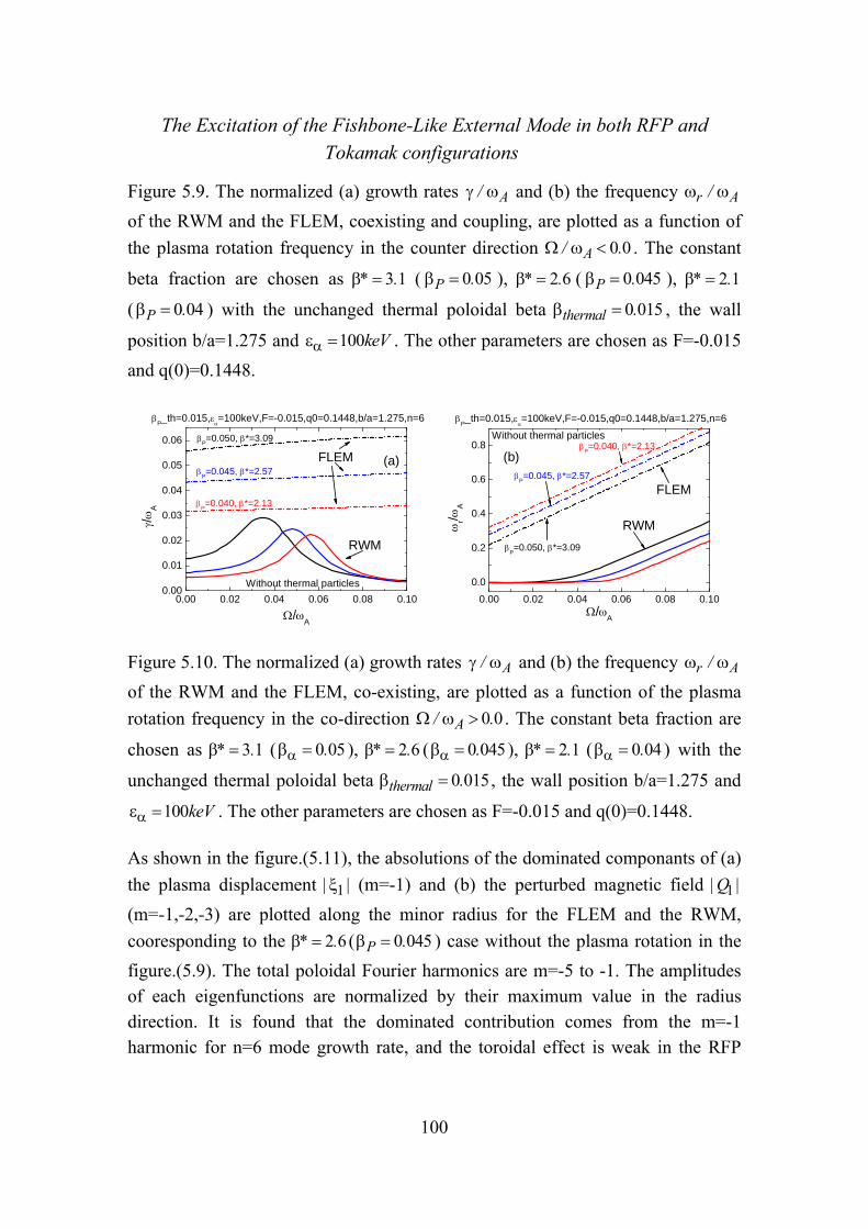
The Excitation of the Fishbone-Like External Mode in both RFP and Tokamak configurations
100
Figure 5.9. The normalized (a) growth rates A/ and (b) the frequency r A/
of the RWM and the FLEM, coexisting and coupling, are plotted as a function of
the plasma rotation frequency in the counter direction 0 0A/ . . The constant
beta fraction are chosen as 3 1* . ( 0 05P . ), 2 6* . ( 0 045P . ), 2 1* .
( 0 04P . ) with the unchanged thermal poloidal beta 0 015thermal . , the wall
position b/a=1.275 and 100keV . The other parameters are chosen as F=-0.015
and q(0)=0.1448.
0.00 0.02 0.04 0.06 0.08 0.100.00
0.01
0.02
0.03
0.04
0.05
0.06
P_th=0.015,
=100keV,F=-0.015,q0=0.1448,b/a=1.275,n=6
Without thermal particles
P=0.040, *=2.13
P=0.045, *=2.57
P=0.050, *=3.09
/
A
/A
FLEM
RWM
(a)
0.00 0.02 0.04 0.06 0.08 0.10
0.0
0.2
0.4
0.6
0.8Without thermal particles
P_th=0.015,
=100keV,F=-0.015,q0=0.1448,b/a=1.275,n=6
r/
A
/A
P=0.045, *=2.57
P=0.050, *=3.09
P=0.040, *=2.13
FLEM
RWM
(b)
Figure 5.10. The normalized (a) growth rates A/ and (b) the frequency r A/
of the RWM and the FLEM, co-existing, are plotted as a function of the plasma
rotation frequency in the co-direction 0 0A/ . . The constant beta fraction are
chosen as 3 1* . ( 0 05. ), 2 6* . ( 0 045. ), 2 1* . ( 0 04. ) with the
unchanged thermal poloidal beta 0 015thermal . , the wall position b/a=1.275 and
100keV . The other parameters are chosen as F=-0.015 and q(0)=0.1448.
As shown in the figure.(5.11), the absolutions of the dominated componants of (a)
the plasma displacement 1| | (m=-1) and (b) the perturbed magnetic field 1|Q |
(m=-1,-2,-3) are plotted along the minor radius for the FLEM and the RWM,
cooresponding to the 2 6* . ( 0 045P . ) case without the plasma rotation in the
figure.(5.9). The total poloidal Fourier harmonics are m=-5 to -1. The amplitudes of each eigenfunctions are normalized by their maximum value in the radius direction. It is found that the dominated contribution comes from the m=-1 harmonic for n=6 mode growth rate, and the toroidal effect is weak in the RFP

The Excitation of the Fishbone-Like External Mode in both RFP and Tokamak configurations
101
plasma for both the FLEM and RWM. The configurations of the eigenfunction for the FLEM and the RWM are similar to each other, and it comfirms the kink-like property of the FLEM. As the results, with the present of the EIs, the FLEM can be considered as another kink-like unstable branch, compared with the RWM branch under the ideal beta limit. The differences are their instabilizing physics machanism, which are the kinetic resonance driven from the EIs for the FLEMs and the magnetic penetration of the resistive wall for the RWMs.
0.0 0.2 0.4 0.6 0.8 1.00.0
0.2
0.4
0.6
0.8
1.0RFP,
P=0.45,*=2.6,b/a=1.275,n=6,hot only
|1|
s
FLEM RWM
m=-1
(a)
0.0 0.2 0.4 0.6 0.8 1.00.0
0.2
0.4
0.6
0.8
1.0
m=-3
m=-2
RFP, P=0.45,*=2.6,b/a=1.275,n=6,hot only
FLEM RWM
|Q1|
s
m=-1
(b)
Figure 5.11. The absolutions of the dominated componants of (a) the plasma
displacement 1| | (m=-1) and (b) the perturbed magnetic field 1|Q | (m=-1,-2,-3)
are plotted along the minor radius for the FLEM and the RWM, cooresponding to
the 2 6* . ( 0 045P . ) case without the plasma rotation in the figure.(5.9). The
total poloidal Fourier harmonics are m=-5 to -1.
5.2 Kinetic effects of EPs with isotropic distribution on FLEMs inTokamakplasma
In the tokamak with similar geometry of the RFP, the same type of the FLEM is observed. The reduced dispersion relation in Eq.(5.3) can be applied near the
critical stabilization of the FLEM, where the mode growth rate A/ is much
smaller than the mode frequency r A/ . Generally for the FLEM in the tokamak,
the growth rate A/ is comparible to the real frequency r A/ , as shown in
the figure.(5.12). By considering the kinetic effect of EPs alone, where i ik FW W and r r
b kW W , we obtain,

The Excitation of the Fishbone-Like External Mode in both RFP and Tokamak configurations
102
2 22 1
2r r i
r b b kn W W W
(5.4-a)
2
ik
r
W
n
(5.4-b)
In the figure.(5.12), we plot the n=1 FLEM (a) growth rate A/ and (b) real
frequency r A/ versus the plasma beta for three case, which are calculated in
the kinetic mechanism of EIs alone with 0 0 3* . ( 0 067* . ) and 0 1 0* .
( 0 19* . ), as well as the full kinetic with 0 1 0* . ( 0 19* . ). The pressure of the
EIs is given by the pressure fraction 2 80(1 )a thermalP / P s P s . The same cross
section to the RFP case is used with the wall position b/a=1.12, and no plasma
rotation is considered. The birth energy of the EIs is kept as 100keV . Similar
to the RFP case, it is found that the FLEM instabilities in the tokamak can also be
triggered by the precession drift motion of the EIs, when the plasma beta is
exceeding a critical value, even without the plasma rotation. The FLEM can be resonance and/or non-resonance, where the dominant non-resonant external kink mode (e.g. m=-1, n=1) couples with the resonant external kink modes (e.g. m=-2, -
3, n=1). The real frequency r A/ of the FLEM, which is much smaller than the
RFP case, is reduced by increasing the plasma beta. It is also observed that the mode instability is reduced by considering the smaller EIs fraction or the full kinetic mechanism. These results indicate the same characteristic of the FLEM to that in the RFP plasma. The ideal wall beta limit is modified by the kinetic effects,
which are 0 0124idealwalllimit . for EIs kinetic effect alone and 0 0139idealwall
limit . for
full kinetic with the no wall beta limit 0 0078nowalllimit . .

The Excitation of the Fishbone-Like External Mode in both RFP and Tokamak configurations
103
0.007 0.008 0.009 0.010 0.011 0.012 0.013 0.014 0.01510-4
10-3
10-2
10-1
100
N=3.74
N=2.11
*0=0.3, Wb=0, Wbk=0 (hot)
*0=1.0, Wb=0, Wbk=0 (hot)
*0=1.0, Wb=0, Wbk=0 (th+hot)
n=1, m=-10 to 5, Ea=100keV, b/a=1.12
/
A
FLM,Tokamak
no-wall limit
(a)
0.007 0.008 0.009 0.010 0.011 0.012 0.013 0.014 0.0150.00
0.02
0.04
0.06
0.08
0.10
N=2.11
N=3.74
*0=0.3, Wb=0, Wbk=0 (hot)
*0=1.0, Wb=0, Wbk=0 (hot)
*0=1.0, Wb=0, Wbk=0 (th+hot)
no-wall limit
n=1, m=-10 to 5, Ea=100keV, b/a=1.12
FLM,hot onlyTokamak
r/
A
(b)
Figure 5.12. The n=1 FLEM (a) growth rate A/ and (b) real frequency r A/
versus the plasma beta are plotted in the kinetic mechanism of EIs alone with
0 0 3* . ( 0 067* . ) and 0 1 0* . ( 0 19* . ), as well as the full kinetic with
0 1 0* . ( 0 19* . ). The wall position is b/a=1.12, no plasma rotation is
considered and the birth energy of the EIs is kept by 100keV .
0.0 0.2 0.4 0.6 0.8 1.0-0.04
0.00
0.04
0.08
0.12
0.16
hot only, Pa/Pth(s)=(1-s2)8
*=0.0125,r/
A=0.058
=0.0103,r/
A=0.091
(m-nq)p,m=-2
(m-nq)p,m=-1
<
>/
A
s
Figure 5.13. The radial profiles of various frequencies of each species over the velocity space and over the poloidal angle are plotted, including the transit
frequency pm nq of the thermal passing ions and the precession frequency of
the trapped EIs dn with different plasma beta 0 0103. ( 2 77N . ) and
0 0125. ( 3 37N . ). The FLEM real frequency 0 091 0 058r A/ . , . with
respect to are also plotted, in which shows the resonance region of the FLEM
(shadow region). The other parameters are chosen as same as that in the figure.(5.12).

The Excitation of the Fishbone-Like External Mode in both RFP and Tokamak configurations
104
As shown in the figure.(5.13), the radial profiles of each frequency averaged over
the velocity space and the poloidal angle are plotted, including the transit
frequency of the thermal passing ions pm nq for m=-1 and m=-2 as well as
the precession frequency of the trapped EIs dn . Two cases with different
plasma beta 0 0103. ( 2 77N . ) and 0 0125. ( 3 37N . ) are considered,
and the FLEM real frequency 0 091 0 058r A/ . , . are also plotted, in which
shows the resonance region (shadow region). Similar to the RFP case, the
resonance for FLEMs occurs under the condition of d rn n as shown in
the resonance oparetor Eq.(2.10), which can be satisfied even at 0 . Compared
with the RFP case, the frequency of FLEM r A/ in the tokamaks is much lower,
due to the lower precession frequency of EPs in a tokamak than in RFP (with
similar geometry). The increased FLEM frequency leads to make the wave-mode
resonance happening difficultly. It is also found that the transit frequency region
pm nq is similar to dn , which causes the cancellation of the EPs kinetic
driven contribution and reduces the FLEM instability.
As shown in the Figure.(5.14), the energy components versus the plasma beta
with 0 1 0* . ( 0 19* . ), are plotted by considering the kinetic effect of EIs alone.
The detailed kinetic energy kW components, by considering the full kinetic effect,
are plotted in the figure.(5.15), including (a) the real part and (b) the imaginary
part of the kinetic energy ikW . It is found that the total potential plasma energy
rbW is increased by reducing the plasma beta , due to the reduced PW (<0), as
shown in the figure.(5.14). With the analysis of the dispersion relation Eq.(5.4-a), ikW modifies the dominated term r
bW . However, the real frequency r A/ is
increased with the reduced plasma beta , which is as same as calculated in the
RFP case. The imaginary part of the kinetic energy ikW becomes zero at the

The Excitation of the Fishbone-Like External Mode in both RFP and Tokamak configurations
105
critical plasma beta , resulting in the zero growth rate of the FLEM as described
in Eq.(5.4-b). By considering the full kinetic effect, the neglected imarginary
kinetic energy ikW is mainly due to cancellation contributed from the thermal
particles as shown in the figure.(5.15). The kinetic contribution of the thermal particle leads to give a stabilizing effect on the FLEM instability. The Landau damping of the transit resonance by the passing thermal particles in Tokamak is weaker than in RFP due to the longer connection length in Tokamaks.
0.009 0.010 0.011 0.012 0.013 0.014-0.006
-0.004
-0.002
0.000
0.002
0.004
0.006
0.008
0.010n=1, m=-10 to 5, Ea=100keV, b/a=1.12
=0.1264,Wb=0 =0.1248,Wbk=0
W/
W2
(*0=1.0)
dWK_real dWK_imag dWb dWb+dWk_real
Figure 5.14. The energy components as described in the dispersion relation in
Eq.(5.4) versus the plasma beta are plotted with 0 1 0* . ( 0 19* . ), by
considering the kinetic effect of EIs alone. The other parameters are same as that in the figure.(5.12).
0.010 0.011 0.012 0.013 0.014 0.015-0.004
-0.002
0.000
0.002
0.004
0.006
0.008
0.010n=1, m=-10 to 5, Ea=100keV, b/a=1.12
real
_W
k/W
2
(*0=1.0,th+hot)
thermal hot full
(a)
0.010 0.011 0.012 0.013 0.014 0.015-0.004
-0.002
0.000
0.002
0.004
0.006
0.008
0.010n=1, m=-10 to 5, Ea=100keV, b/a=1.12
thermal hot full
imag
_W
k/W
2
(*0=1.0,th+hot)
(b)
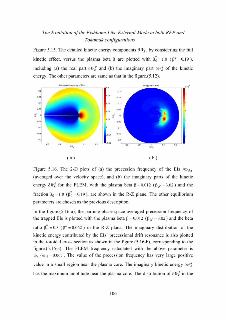
The Excitation of the Fishbone-Like External Mode in both RFP and Tokamak configurations
106
Figure 5.15. The detailed kinetic energy components kW , by considering the full
kinetic effect, versus the plasma beta are plotted with 0 1 0* . ( 0 19* . ),
including (a) the real part rkW and (b) the imaginary part i
kW of the kinetic
energy. The other parameters are same as that in the figure.(5.12).
( a ) ( b )
Figure 5.16. The 2-D plots of (a) the precession frequency of the EIs dn
(averaged over the velocity space), and (b) the imaginary parts of the kinetic
energy ikW for the FLEM, with the plasma beta 0 012. ( 3 02N . ) and the
fraction 0 1 0. ( 0 0 19* . ), are shown in the R-Z plane. The other equilibrium
parameters are chosen as the previous description.
In the figure.(5.16-a), the particle phase space averaged precession frequency of
the trapped EIs is plotted with the plasma beta 0 012. ( 3 02N . ) and the beta
ratio 0 0 3* . ( 0 062* . ) in the R-Z plana. The imaginary distribution of the
kinetic energy contributed by the EIs’ precessional drift resonance is also plotted in the toroidal cross section as shown in the figure.(5.16-b), corresponding to the figure.(5.16-a). The FLEM frequency calculated with the above parameter is
0 067r A/ . . The value of the precession frequency has very large positive
value in a small region near the plasma core. The imaginary kinetic energy ikW
has the maximum amplitude near the plasma core. The distribution of ikW in the

The Excitation of the Fishbone-Like External Mode in both RFP and Tokamak configurations
107
Tokamak configuration is similar to the RFP case. The asymmetry distribution of ikW is because of the contribution from the dominated m=-1 harmonic.
1.0 1.1 1.2 1.3 1.4 1.5 1.6 1.7 1.80.007
0.008
0.009
0.010
0.011
0.012
0.013 critical for FLM, Ea=100keV W
bk=0, Ea=100keV
critical for FLM, Ea=150keV W
bk=0, Ea=150keV
n=1, m=-10 to 5, Tokamak
b/a
no-wall limit, =0.00781.92.02.12.22.32.42.52.62.72.82.93.03.13.23.33.43.5
N
Figure 5.17. The instability window of the n=1 FLEM is plotted in the plane of the
plasma beta (left) and N (right) versus the wall position b/a. The black dashed
line represents the no wall beta limit ( 0 0078nowalllimit . ). The red line and the blue
line represent the boundary of the instability window for the two cases: (a)
0 0 3* . ( 0 067* . ) and 100keV ; (b) 0 0 51* . ( 0 107* . ) and 150keV
respectively. The solid lines denote the ideal wall beta limit that is modified by the kinetic effect, and the dashed lines denote the stable/unstable boundary of the FLEMs. No plasma rotation is considered.
Figure.(5.17) shows the instability window (shaded area) of the n=6 FLEM driven
by the precession resonance of the EIs, in the ( N )-b/a plane. The black dashed
line represents the no wall beta limit ( 0 0078nowalllimit . ). The red line and the blue
line represent the boundary of the instability window for the two cases: (a)
0 0 3* . ( 0 067* . ) and 100keV ; (b) 0 0 51* . ( 0 107* . ) and 150keV
respectively. The solid lines denote the ideal wall beta limit that is modified by the kinetic effect, and the dashed lines denote the stable/unstable boundary of the FLEMs. The above and to the right of the shaded area represents the unstable region of the ideal kink, while the below and to the left of the shaded area represents the stable region of the FLEM. For a given wall position b/a, each
The Excitation of the Fishbone-Like External Mode in both RFP and Tokamak configurations
108
FLEM has the instability window opened along the axis. On the other side, each
FLEM has its instability window in the b/a axis, for a given value. It is found
that higher leads to the broader instability window in both and b/a parameter
spaces. The trigger of the FLEM requires farther wall position when the plasma
beta is low. However, the results indicate that the FLEM is unstable only if the
plasma beta exceeds the no wall beta limit 0 0078nowalllimit . .
5.3 Summary
The Fishbone-Like External kink Mode (FLEM) instability driven by the precession drift motion of Energetic Particles is investigated in both RFP and Tokamak plasmas, by using the MHD-kinetic hybrid toroidal stability code MARS-K. The ideal kink dispersion relation is adopted in order to obtain more detailed physical understanding. The EPs is the energetic ions from the NBI, described by using isotropic model. The FLEM instability has the similar characteristic in both magnetic confinement configurations. In this work, the effects of the equilibrium parameters, including the plasma pressure, the wall position, the birth energy and the density of the EIs, are studied repectively.
In the RFP plasma, the non-resonant FLEM instability is predicted. In general, the instability of FLEM does not depend on the wall resistivity. The analysis with the
dispersion relation indicates that the frequency r of FLEM is determined by the
potential plasma energy bW , which is effected significantly by the total plasma
pressure and the wall position. The higher plasma pressure and the farther wall
position leads to smaller bW (smaller frequency r ). If the frequency r falls
inside the range satisfying the resonant condition with the precession frequency of a given type of EPs, the instability of FLEM can appear. The instability of the
FLEM is enhanced by the reduced bW . On the other side, the enhanced instability
of the FLEM is also found by increasing the precession frequency dn (higher
birth energy ) and the density Na/Ne of EIs for a given type of the plasma
equilibrium. However, the FLEM property is more sensitive to the EIs precession
dn frequency than the EIs density Na/Ne. In the full kinetic mechanism, the
cancellation of the kinetic effect between the thermal particles (transit resonance of passing particles) and the EIs exists, where the thermal particle gives a

The Excitation of the Fishbone-Like External Mode in both RFP and Tokamak configurations
109
stabilizing effect on the FLEMs. With the presence of EPs in the plasma, it is found that the FLEM and the RWM can coexist or couple to each other, depending on the plasma parameters.
The same type of the instability is observed with the plasma beta nowall idealwalllimit limit in the Tokamak plasmas, where the dominant non-resonant
external kink mode (e.g. m=-1, n=1) couples with the resonant external kink modes (e.g. m=-2, -3, n=1). The similar nature of the FLEMs to that in RFPs is observed. Nevertheless, in Tokamak the frequency of FLEM is much lower than what in RFP due to the lower precession frequency of EPs in a Tokamak than in RFP (with similar geometry). Furthermore, the Landau damping of the transit resonance by the passing thermal particles in Tokamak is weaker than in RFP due to the longer connection length in Tokamaks.

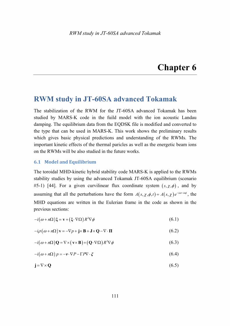
RWM study in JT-60SA advanced Tokamak
111
Equation Chapter (Next) Section 1
Chapter 6
6 RWM study in JT-60SA advanced Tokamak
The stabilization of the RWM for the JT-60SA advanced Tokamak has been studied by MARS-K code in the fuild model with the ion acoustic Landau damping. The equilibrium data from the EQDSK file is modified and converted to the type that can be used in MARS-K. This work shows the preliminary results which gives basic physical predictions and understanding of the RWMs. The important kinetic effects of the thermal paricles as well as the energetic beam ions on the RWMs will be also studied in the future works.
6.1 ModelandEquilibrium
The toroidal MHD-kinetic hybrid stability code MARS-K is applied to the RWMs stability studies by using the advanced Tokamak JT-60SA equilibrium (scenario
#5-1) [44]. For a given curvilinear flux coordinate system , ,s , and by
assuming that all the perturbations have the form , , , , i t inA s t A s e , the
MHD equations are written in the Eulerian frame in the code as shown in the previous sections:
2i n R ξ v ξ (6.1)
i n p v j B J Q Π (6.2)
2i n R Q v B Q (6.3)
i n p P P v ξ (6.4)
j Q (6.5)

RWM study in JT-60SA advanced Tokamak
112
In this work, we studies the stabilized effect of the plasma rotation on the RWMs in the fuild model, which uses the ion acoustic Landau damping for each (m, n) component of the perturbered toroidal motion of the plasma. The model for the thermal ion acoustic Landau damping is written by [3],
| | | | , | || | th ik v Π v (6.6)
Where | | ( / ) /k m q n R is the parallel wave number, ,th iv is the ion thermal
velocity, and | |v is the perturbed parallel velocity of the plasma. The damping
effect enters into the MHD equations (momentum equation in Eq. (6.2)) by giving
an appropriate strength parameter | | .
0.0 0.5 1.0 1.5 2.0 2.5 3.0
-1.0
-0.5
0.0
0.5
1.0
effective wall
plasma surface
Z/R
0
R/R0
plasma
JT-60SA (SCENARIO #5-1)
Figure 6.1. The geometry of the smoothed plasma surface (red line), the double shell (blue line) and the calculated effective wall (black line) are plotted in the R-Z plane. The major radius R0 is R0=3.25(m).
As shown in the figure.(6.1), the cross-section of the plasma shape and the double resistive wall designed in the JT-60SA are plotted in the R-Z plane. The double wall and the plasma facing components outside the plasma are replaced by an effective single wall which is convenient to the computation by using the thin-shell approximation. The plasma surface around the X-point (on the side of the

RWM study in JT-60SA advanced Tokamak
113
lower divertors) is also smoothed while it affects the plasma equilibrium very slightly. The equilibrium data of the JT-60SA scenario #5-1 from the EQDSK file are shown as the radial profiles in the figure.(6.2), including the temperature of the thermal ions Ti and electrons Te, the density of the thermal ions Ni and electrons Ne as well as the energetic ions Na from the NBI injection, the pressure components of each species, and the total plasma current density. The equilibrium parameter chosen in this work are the major radius R0=3.25(m), the toroidal
magnetic field BT=1.5631(T) and the normalized beta 3.2N . All the
equilibrium data, including the smoothed plasma shape, effective wall and the equilibrium profiles, is regenerated by using the equilibrium code CHEASE, and converts to the type as the inputs of the code MARS-K.
0.0 0.2 0.4 0.6 0.8 1.00.0
2.0x10³
4.0x10³
6.0x10³
8.0x10³Temperature of electrons, ions.
T(e
V)
s=sqrt()
Te Ti
(a)
0.0 0.2 0.4 0.6 0.8 1.00.0
2.0x10¹⁹
4.0x10¹⁹
6.0x10¹⁹
8.0x10¹⁹
ne ni n_NBI*10
n
(m-3)
s=sqrt()
Density of electrons and ions
(b)
0.0 0.2 0.4 0.6 0.8 1.00.0
5.0x10⁴
1.0x10⁵
1.5x10⁵
P(p
a)
s=sqrt()
P_thermal P_NBI P_total P_NBI/P_thermal
(c)
0.0
0.2
0.4
0.6
0.8
1.0Pressure and Fraction(P
nbi/P
thermal)
Fra
ctio
n,P
nbi/P
ther
ma
l
0.0 0.2 0.4 0.6 0.8 1.00.0
2.0x10⁵
4.0x10⁵
6.0x10⁵
8.0x10⁵
1.0x10⁶
J(A
/m2 )
s=sqrt()
Total plasma current (A/m2)
(d)
Figure 6.2. The plots of the radial profile of the equilibrium, includes (a) the temperature of the thermal electrons and ions, (b) the density of the thermal electrons and ions as well as the energetic ions, (c) the pressure componnents of each species and (d) the total plasma current density.

RWM study in JT-60SA advanced Tokamak
114
In the figure.(6.3), it shows the radia profile of calculated safety factor q, and the rotation frequency . It is found that the reversed q-profile (qmin>1) with the beta
parameter 3.2N has its value at the plasma core q(0)=4.4 and at the plasma
edge q(a)=6.7. The rotation frequency is peaked largely near the plasma edge, and it is found that at the region q~3 the rotation becomes flat especially. The
remarked rotation frequency in the following results / A is the rotation
frequency at the plasma center (0) , and it is normalized by the Alfven frequency
0 0 0 0/A B R . The rotation frequency at q=3 is about 30% of the value at the
plasma center.
0.0 0.2 0.4 0.6 0.8 1.00
1
2
3
4
5
6
7
8
N=3.2467,q
0=4.40705,q
a=6.70896
safe
ty f
acto
r q
s
0.0
0.2
0.4
0.6
0.8
1.0
rota
tion
freq
uenc
y
/(0
)
Figure 6.3. The toroidal rotation frequency (red line) and the safety factor q (black
line) with the beta ratio 3.2N are plotted as the radia profile. The marked
plasma rotation frequencies / A given in the following results are the values of
plasma rotation frequency (normalized by the Alfven frequency A ) at the plasma
center.
6.2 PredictedJT‐60SAresults
The equilibrium parameters we chosen in our study of the n=1 RWM stabilization by the toroidal plasma rotation for the JT-60SA advanced Tokamak, includes the
wall position b/a=1.12, the plasma beta 3.2N with poloidal harmonic number
m (from -12 to 40). Firstly as shown in the figure.(6.4), the no-wall beta limit

RWM study in JT-60SA advanced Tokamak
115
( ) 1.93N no wall and the ideal-wall limit ( ) 5.59N ideal wall are calculated
respectively. The parameter C is defined as,
no wallN N
ideal wall no wallN N
C
(6.7)
Where the range of the parameter C is from 0 (at the no-wall beta limit) to 1 (at
the ideal-wall beta limit). Here we choose 3.2N , due to the plasma pressure
given by the EQDSK file, and we obtain the parameter C =34.7%.
0 1 2 3 4 5 6 70.00
0.01
0.02
0.03
0.04
0.05
N=3.2
n=1,m=-12 to 40,//=0.05,b/a=1.12
no wall -limit
N=1.931
ideal wall -limit
N=5.596
/
A
N
Figure 6.4. The no wall -limit and ideal wall -limit of RWM in JT-60SA are
plotted, which are N (no wall) =1.931 and N (ideal wall) =5.596 respectively. The
poloidal Fourier harmonics number m from -12 to 40 and the toroidal mode number n=1 are taken into the calculation. The other parameters are wall position
b/a=1.12 and strength parameter of the parallel sound wave damping | | 0.05 .
In the figure.(6.5), the n=1 RWM growth rate and real frequency versus the plasma rotation are plotted in three cases, which has the uniform rotation profile
with the strength parameter of the ion acoustic damping (a) | | 0.5 , and the
experimental rotation profile (shown in the figure.(6.3)) with the strength
parameter (b) | | 0.5 and (c) | | 1.0 . It is found that the critical rotation
frequency required by considering the peaked rotation profile, is increased slightly by increasing the strength parameter. Compared between the case (a) and (b)

RWM study in JT-60SA advanced Tokamak
116
(where | | 0.5 ), it is found that the critical rotation frequency for the uniform case
1 / 0.05C A is much smaller than the peaked rotation case 2 / 0.225C A . The
ratio of the critical rotation frequency for both cases is 1 2/ 0.22C C , and it
indicates that the stabilizing effect contributed by the ion acoustic Landau damping is mainly located at the region q>3 as shown in the figure.(6.3). As the results, this peaked rotation profile gives less stabilization of the RWM in the JT-60SA equilibrium than a flat profile.
0.00 0.05 0.10 0.15 0.20 0.25 0.300.0
1.0x10⁻⁴
2.0x10⁻⁴
3.0x10⁻⁴
||=0.5
peaked rotation peaked rotation constant rotation
||=1.0
N=3.2467,q
0=4.40705,q
a=6.70896
/
A
/A
||=0.5
(a)
0.00 0.05 0.10 0.15 0.20 0.25 0.300.0
5.0x10⁻⁵
1.0x10⁻⁴
1.5x10⁻⁴
2.0x10⁻⁴
||=1.0
||=0.5
||=0.5
N=3.2467,q
0=4.40705,q
a=6.70896
peaked rotation peaked rotation constant rotation
r/
A
/A (b)
Figure 6.5. The n=1 (a) RWM growth rate /A and (b) real frequency r/A
versus plasma rotation frequency /A are plotted for different | | =1.0, 0.5,
0.5(uniform velocity). The other parameters are N=3.2467, q0=4.407, qa=6.709,

RWM study in JT-60SA advanced Tokamak
117
b/a=1.12. The RWM can be stabilized due to viscous damping, and the critical
plasma rotation frequency /A for RWM stabilized decreases with parameter //.
However, the critical rotation frequency, in particular for the uniform rotation
profile 1 / 0.05C A , is a little large, compared with the predicted results of the
other advanced equilibrium [75]. In order to find out the reason behind the results,
the RWM growth rate versus the wall position with | | =0.5 and different rotation
frequency is plotted as shown in the figure.(6.6). The stability window contributed by the ion acoustic damping is opened at the wall position b/a=1.25 when the
rotation frequency is equal to 1 / 0.05 ~ 0.1C A , and it is enlarged by increasing
the rotation frequency. We find that the critical rotation frequency can be reduced by moving the wall position a little far away from the plasma.
As shown in the figure.(6.7), the n=1 RWM eigenfunction of the perturbed displacement and the magnetic field in the radial direction are plotted with the
parameter /A=0.1, | | =0.5, b/a=1.12. The poloidal Fourier harmonics number
m is from -12 to 40. It is found that the amplitude of the m=2 mode is much larger than the others, which is most unstable mode and gives major contribution to the n=1 mode growth rate. As the results, the dominated instability is an external resonance (2,1) mode. The stronge mode coupling is also found due to the significant toroidal effect.
1.0 1.1 1.2 1.3 1.4 1.5 1.610-6
10-5
10-4
10-3
10-2
10-1
b/a=1.12
N=3.2,q
0=4.4,q
a=6.7,
//=0.5
/A=0.225
/A=0.175
/A=0.1
/A=0.05
/A=0.005
stable window
/
A
b/a

RWM study in JT-60SA advanced Tokamak
118
Figure 6.6. The n=1 RWM growth rate /A versus wall position b/a are plotted
for different plasma rotation frequency /A=0.225, 0.175, 0.1, 0.05, 0.005. The
other parameters are N=3.2467, q0=4.407, qa=6.709, | | =0.5. The stability
window appears and is enlarged by an increase in plasma rotation frequency /A.
0 0.2 0.4 0.6 0.8 1-0.5
0
0.5
1
-12 -12-12 -12 -12 -12 -12 -12 -12-12 -12-12-12-12-12-12-12-11 -11-11 -11 -11 -11 -11 -11 -11-11 -11-11-11-11-11-11-11-10 -10-10 -10 -10 -10 -10 -10 -10-10 -10-10-10-10-10-10-10-9 -9 -9 -9 -9 -9 -9 -9 -9 -9 -9 -9 -9-9-9 -9-9-8 -8 -8 -8 -8 -8 -8 -8 -8 -8 -8 -8 -8-8-8 -8-8-7 -7 -7 -7 -7 -7 -7 -7 -7 -7 -7 -7 -7-7-7 -7-7-6 -6 -6 -6 -6 -6 -6 -6 -6 -6 -6 -6 -6-6-6 -6-6-5 -5 -5 -5 -5 -5 -5 -5 -5 -5 -5 -5 -5-5-5 -5-5-4 -4 -4 -4 -4 -4 -4 -4 -4 -4 -4 -4 -4-4-4 -4-4-3 -3 -3 -3 -3 -3 -3 -3 -3 -3 -3 -3 -3-3-3 -3-3-2 -2 -2 -2 -2 -2 -2 -2 -2 -2 -2 -2 -2-2-2 -2-2-1-1 -1 -1 -1 -1 -1 -1 -1 -1 -1 -1 -1-1-1 -1-1
0 0 0 0 00
0 0 0
0 0 0 0 00
0
0
1
1 11
1
1
1 11
11
1 1 1
1
1
1
2 2 2 2 2
2
22
2
2
22 2 2
2
2
2
3 3 3 3 33
3 33
33
3 3 3
3
3
3
4 4 4 4 4 44 4 4
4 4
4 4 4 4445 5 5 5 5 5 5 5 5 5 5
5 5 5
5
5
5
6 6 6 6 6 6 6 6 6 6 6 6 6 6 6 667 7 7 7 7 7 7 7 7 7 7 7 7 7
7
77
8 8 8 8 8 8 8 8 8 8 8 8 8 88
8
8
9 9 9 9 9 9 9 9 9 9 9 9 9 99
9
9
10 1010 10 10 10 10 10 10 10 1010 101010101011 1111 11 11 11 11 11 11 11 1111 1111
11
1111
12 1212 12 12 12 12 12 12 12 12 12 1212121212
13 1313 13 13 13 13 13 13 13 1313 131313
1313
14 1414 14 14 14 14 14 14 14 1414 1414141414
15 1515 15 15 15 15 15 15 15 1515 151515151516 1616 16 16 16 16 16 16 16 1616 161616161617 1717 17 17 17 17 17 17 17 1717 171717171718 1818 18 18 18 18 18 18 18 1818 181818181819 1919 19 19 19 19 19 19 19 1919 191919191920 2020 20 20 20 20 20 20 20 2020 202020202021 2121 21 21 21 21 21 21 21 2121 212121212122 2222 22 22 22 22 22 22 22 2222 222222222223 2323 23 23 23 23 23 23 23 2323 232323232324 2424 24 24 24 24 24 24 24 2424 242424242425 2525 25 25 25 25 25 25 25 2525 252525252526 2626 26 26 26 26 26 26 26 2626 26262626
2627 2727 27 27 27 27 27 27 27 2727 272727272728 2828 28 28 28 28 28 28 28 2828 282828282829 2929 29 29 29 29 29 29 29 2929 292929292930 3030 30 30 30 30 30 30 30 3030 303030303031 3131 31 31 31 31 31 31 31 3131 313131313132 3232 32 32 32 32 32 32 32 3232 323232323233 3333 33 33 33 33 33 33 33 3333 333333333334 3434 34 34 34 34 34 34 34 3434 343434343435 3535 35 35 35 35 35 35 35 3535 353535353536 3636 36 36 36 36 36 36 36 3636 363636363637 3737 37 37 37 37 37 37 37 3737 373737373738 3838 38 38 38 38 38 38 38 3838 383838383839 3939 39 39 39 39 39 39 39 3939 393939393940 4040 40 40 40 40 40 40 40 4040 4040404040
s
real
Xi1
0 0.2 0.4 0.6 0.8 1-0.5
-0.4
-0.3
-0.2
-0.1
0
0.1
0.2
0.3
-12 -12-12 -12 -12 -12 -12 -12 -12-12 -12-12-12-12-12-12-12-11 -11-11 -11 -11 -11 -11 -11 -11-11 -11-11-11-11-11-11-11-10 -10-10 -10 -10 -10 -10 -10 -10-10 -10-10-10-10-10-10-10-9 -9 -9 -9 -9 -9 -9 -9 -9 -9 -9 -9 -9-9-9 -9-9-8 -8 -8 -8 -8 -8 -8 -8 -8 -8 -8 -8 -8-8-8 -8-8-7 -7 -7 -7 -7 -7 -7 -7 -7 -7 -7 -7 -7-7-7 -7-7-6 -6 -6 -6 -6 -6 -6 -6 -6 -6 -6 -6 -6-6-6 -6-6-5 -5 -5 -5 -5 -5 -5 -5 -5 -5 -5 -5 -5-5-5 -5-5-4 -4 -4 -4 -4 -4 -4 -4 -4 -4 -4 -4 -4-4-4 -4-4-3 -3 -3 -3 -3 -3 -3 -3 -3 -3 -3 -3 -3-3-3 -3-3-2 -2 -2 -2 -2 -2 -2 -2 -2 -2 -2 -2 -2-2-2 -2-2-1-1 -1 -1 -1 -1 -1 -1 -1 -1 -1 -1 -1-1-1 -1-1
0 0 0 0 0
0
00 0
00
0 0 0
0
00
1
1 11
1
1
11
1
1
1
11 1
1
1
1
22 2
2
2
2
22
2
2
2
22 2
2
2
2
3 3 3 3 33
33
3
3
3
3 33
3
3
3
4 4 4 4 44
4 44 4 4
4 4 4 4
44
5 5 5 5 5 5 5 5 5 5 55
55
5
5
5
6 6 6 6 6 6 6 6 6 6 6 66
66
6
6
7 7 7 7 7 7 7 7 7 7 77 7
77
7
7
8 8 8 8 8 8 8 8 8 8 8 8 8 8
8
8
8
9 9 9 9 9 9 9 9 9 9 9 9 9 9
99
9
10 1010 10 10 10 10 10 10 10 1010 1010
10
10
10
11 1111 11 11 11 11 11 11 11 11 11 1111
11
11
1112 1212 12 12 12 12 12 12 12 1212 121212
12
12
13 1313 13 13 13 13 13 13 13 1313 1313
13
13
13
14 1414 14 14 14 14 14 14 14 1414 1414
1414
14
15 1515 15 15 15 15 15 15 15 1515 151515
15
15
16 1616 16 16 16 16 16 16 16 1616 1616
16
16
16
17 1717 17 17 17 17 17 17 17 1717 17171717
17
18 1818 18 18 18 18 18 18 18 1818 181818
18
18
19 1919 19 19 19 19 19 19 19 1919 191919191920 2020 20 20 20 20 20 20 20 2020 202020
20
20
21 2121 21 21 21 21 21 21 21 2121 21212121
21
22 2222 22 22 22 22 22 22 22 2222 2222222222
23 2323 23 23 23 23 23 23 23 2323 23232323
23
24 2424 24 24 24 24 24 24 24 2424 242424242425 2525 25 25 25 25 25 25 25 2525 2525252525
26 2626 26 26 26 26 26 26 26 2626 2626262626
27 2727 27 27 27 27 27 27 27 2727 2727272727
28 2828 28 28 28 28 28 28 28 2828 2828282828
29 2929 29 29 29 29 29 29 29 2929 292929292930 3030 30 30 30 30 30 30 30 3030 3030303030
31 3131 31 31 31 31 31 31 31 3131 313131313132 3232 32 32 32 32 32 32 32 3232 3232323232
33 3333 33 33 33 33 33 33 33 3333 333333333334 3434 34 34 34 34 34 34 34 3434 343434343435 3535 35 35 35 35 35 35 35 3535 35353535
3536 3636 36 36 36 36 36 36 36 3636 363636363637 3737 37 37 37 37 37 37 37 3737 373737373738 3838 38 38 38 38 38 38 38 3838 383838383839 3939 39 39 39 39 39 39 39 3939 393939393940 4040 40 40 40 40 40 40 40 4040 4040404040
s
imag
Xi1
(a)
0 0.2 0.4 0.6 0.8 1-0.04
-0.03
-0.02
-0.01
0
0.01
0.02
0.03
0.04
-12 -12-12 -12 -12 -12 -12 -12 -12-12 -12-12-12-12-12-12-12-11 -11-11 -11 -11 -11 -11 -11 -11-11 -11-11-11-11-11-11-11-10 -10-10 -10 -10 -10 -10 -10 -10-10 -10-10-10-10-10-10-10-9 -9 -9 -9 -9 -9 -9 -9 -9 -9 -9 -9 -9-9-9 -9-9-8 -8 -8 -8 -8 -8 -8 -8 -8 -8 -8 -8 -8-8-8 -8-8-7 -7 -7 -7 -7 -7 -7 -7 -7 -7 -7 -7 -7-7-7 -7-7-6 -6 -6 -6 -6 -6 -6 -6 -6 -6 -6 -6 -6-6-6 -6-6-5 -5 -5 -5 -5 -5 -5 -5 -5 -5 -5 -5 -5-5-5 -5-5-4 -4 -4 -4 -4 -4 -4 -4 -4 -4 -4 -4 -4-4-4 -4-4-3 -3 -3 -3 -3 -3 -3 -3 -3 -3 -3 -3 -3-3-3 -3-3-2 -2 -2 -2 -2 -2 -2 -2 -2 -2 -2 -2 -2-2-2 -2-2-1 -1 -1 -1 -1 -1 -1 -1 -1 -1 -1 -1 -1-1-1 -1-10 0 0 0 0 0 0 0 0 0 0 0 0 0 0 0011 1 1 1 1
11 1 1 1 1 1 1 1 11
2 2 2 2 22
2
2
22
22 2 2
2
22
3 3 3 3 3 33
3
33
33
3 33
33
4 4 4 4 4 4
4 4
44
4
4 4 4 4
44
5 5 5 5 5 5 5 5
5 55
5
5 5 5
55
6 6 6 6 6 6 6 6 6 6
66 6
66
66
7 7 7 7 7 7 7 77 7 7 7
77
7
7
7
8 8 8 8 8 8 8 8 8 88 8
88
8
88
9 9 9 9 9 9 9 9 9 9 9 99
9
99
9
10 1010 10 10 10 10 10 10 10 101010
10
10
1010
11 1111 11 11 11 11 11 11 11 1111 111111
11
1112 1212 12 12 12 12 12 12 12 1212
1212
12
1212
13 1313 13 13 13 13 13 13 13 1313 1313
13
13
13
14 1414 14 14 14 14 14 14 14 1414 1414
14
1414
15 1515 15 15 15 15 15 15 15 1515 1515
15
15
15
16 1616 16 16 16 16 16 16 16 1616 16161616
16
17 1717 17 17 17 17 17 17 17 1717 1717
17
17
17
18 1818 18 18 18 18 18 18 18 1818 181818
18
18
19 1919 19 19 19 19 19 19 19 1919 1919
19
19
19
20 2020 20 20 20 20 20 20 20 2020 2020
20
20
20
21 2121 21 21 21 21 21 21 21 2121 2121212121
22 2222 22 22 22 22 22 22 22 2222 222222
22
22
23 2323 23 23 23 23 23 23 23 2323 23232323
2324 2424 24 24 24 24 24 24 24 2424 242424
24
24
25 2525 25 25 25 25 25 25 25 2525 252525
25
2526 2626 26 26 26 26 26 26 26 2626 262626
26
2627 2727 27 27 27 27 27 27 27 2727 2727
27
27
2728 2828 28 28 28 28 28 28 28 2828 282828282829 2929 29 29 29 29 29 29 29 2929 2929
29
29
2930 3030 30 30 30 30 30 30 30 3030 303030303031 3131 31 31 31 31 31 31 31 3131 313131
31
3132 3232 32 32 32 32 32 32 32 3232 323232323233 3333 33 33 33 33 33 33 33 3333 333333
33
3334 3434 34 34 34 34 34 34 34 3434 34343434
3435 3535 35 35 35 35 35 35 35 3535 353535353536 3636 36 36 36 36 36 36 36 3636 36363636
3637 3737 37 37 37 37 37 37 37 3737 373737373738 3838 38 38 38 38 38 38 38 3838 38383838
3839 3939 39 39 39 39 39 39 39 3939 393939393940 4040 40 40 40 40 40 40 40 4040 4040404040
s
real
Q1
0 0.2 0.4 0.6 0.8 1-0.03
-0.02
-0.01
0
0.01
0.02
0.03
-12 -12-12 -12 -12 -12 -12 -12 -12-12 -12-12-12-12-12-12-12-11 -11-11 -11 -11 -11 -11 -11 -11-11 -11-11-11-11-11-11-11-10 -10-10 -10 -10 -10 -10 -10 -10-10 -10-10-10-10-10-10-10-9 -9 -9 -9 -9 -9 -9 -9 -9 -9 -9 -9 -9-9-9 -9-9-8 -8 -8 -8 -8 -8 -8 -8 -8 -8 -8 -8 -8-8-8 -8-8-7 -7 -7 -7 -7 -7 -7 -7 -7 -7 -7 -7 -7-7-7 -7-7-6 -6 -6 -6 -6 -6 -6 -6 -6 -6 -6 -6 -6-6-6 -6-6-5 -5 -5 -5 -5 -5 -5 -5 -5 -5 -5 -5 -5-5-5 -5-5-4 -4 -4 -4 -4 -4 -4 -4 -4 -4 -4 -4 -4-4-4 -4-4-3 -3 -3 -3 -3 -3 -3 -3 -3 -3 -3 -3 -3-3-3 -3-3-2 -2 -2 -2 -2 -2 -2 -2 -2 -2 -2 -2 -2-2-2 -2-2-1 -1 -1 -1 -1 -1 -1 -1 -1 -1 -1 -1 -1-1-1 -1-10 0 0 0 0 0 0 0 0 0 0 0 0 0 0 001
1 11 1 1
1
1 1 1 1 1 1 1 111
2 2 2 2 22
2
2
2
2
22
22 2
22
3 3 3 3 3 33
3
3
3
33
3 33
33
4 4 4 4 4 4
44
44
4
44
44 44
5 5 5 5 5 5 55
55
55
55 5
55
6 6 6 6 6 66 6 6 6
66
6 6 6
66
7 7 7 7 7 7 7 77 7 7 7
77
7
77
8 8 8 8 8 8 8 8 8 8
88
8 8 8
88
9 9 9 9 9 9 9 9 9 9 9 9 99 9
9
9
10 1010 10 10 10 10 10 10 10 10101010
10
10
10
11 1111 11 11 11 11 11 11 11 1111 111111
11
11
12 1212 12 12 12 12 12 12 12 1212 1212
12
12
12
13 1313 13 13 13 13 13 13 13 1313 131313
13
13
14 1414 14 14 14 14 14 14 14 1414 1414
14
1414
15 1515 15 15 15 15 15 15 15 1515 151515
15
15
16 1616 16 16 16 16 16 16 16 1616 1616161616
17 1717 17 17 17 17 17 17 17 1717 171717
17
17
18 1818 18 18 18 18 18 18 18 1818 1818181818
19 1919 19 19 19 19 19 19 19 1919 191919
19
19
20 2020 20 20 20 20 20 20 20 2020 202020
202021 2121 21 21 21 21 21 21 21 2121 2121
21
21
2122 2222 22 22 22 22 22 22 22 2222 222222
222223 2323 23 23 23 23 23 23 23 2323 2323
23
23
23
24 2424 24 24 24 24 24 24 24 2424 2424242424
25 2525 25 25 25 25 25 25 25 2525 252525
25
25
26 2626 26 26 26 26 26 26 26 2626 262626
26
2627 2727 27 27 27 27 27 27 27 2727 272727
27
2728 2828 28 28 28 28 28 28 28 2828 2828
28
28
2829 2929 29 29 29 29 29 29 29 2929 292929292930 3030 30 30 30 30 30 30 30 3030 3030
30
30
3031 3131 31 31 31 31 31 31 31 3131 313131313132 3232 32 32 32 32 32 32 32 3232 323232
32
3233 3333 33 33 33 33 33 33 33 3333 33333333
3334 3434 34 34 34 34 34 34 34 3434 343434
34
3435 3535 35 35 35 35 35 35 35 3535 353535
35
3536 3636 36 36 36 36 36 36 36 3636 363636363637 3737 37 37 37 37 37 37 37 3737 373737
37
3738 3838 38 38 38 38 38 38 38 3838 383838383839 3939 39 39 39 39 39 39 39 3939 39393939
3940 4040 40 40 40 40 40 40 40 4040 4040
404040
s
imag
Q1
(b)
Figure 6.7. The n=1 RWM eigenfunction of (a) the perturbered displacement 1
and (b) the magnetic field Q1 in the radial direction are plotted with /A=0.1,
| | =0.5, b/a=1.12. The poloidal Fourier harmonics number m is from -12 to 40.
The dominated mode number is m=2.

Conclusions
119
Conclusions
Shaping effect on MHD stabilities in reversed field pinch (RFP) plasmas:
We have studied the shaping effects on RFP plasmas by using the MHD-kinetic hybrid toroidal stability code MARS-K. Both elongation and triangularity effects have been investigated. The studies focus on the most important MHD modes in
RFPs. The first topic is the p limit set by the RWM (the ideal kink mode)
instability, where the ideal-wall limit and the stabilization by drift kinetic
damping are studied; and an in-depth analysis has been carried out for physics understanding. The second topic is on the linear stability of the resistive mode (the
dynamo modes) under shaping effects in the low RFP plasmas, and the
comparison with the circular case. Finally we report a computational result on the bootstrap fraction in shaped RFP plasmas.
The RFP magnetic configuration is characterized by a strong poloidal magnetic field and reversed toroidal field. Shaping effects in RFP induce a stronger poloidal mode coupling than the circular case, due to the variation of the poloidal field strength along the poloidal angle. Moreover, shaping also introduces multiple trapped regions. As a consequence, the shaping effects lead to quite a different conclusion from that of a tokamak. The detailed results are summarized as follows.
For the RWM, shaping yields a lower ideal-wall limit, and increases the growth
rate of the mode due to the reduction of the vacuum energy component Wvb. In
this case, the kinetic damping becomes more significant than the circular case,
meaning that the kinetic stabilization requires a lower p value, and possibly also a
slightly slower rotation. However, the kinetic contribution is still dominant by the ion acoustic Landau damping of passing particles, thus requiring a critical plasma rotation still in the ion acoustic frequency range. Furthermore, the stabilization
windows in shaped RFP become narrower in both p and b/a parameter spaces.
Appearance of multiple trapping regions due to the shaping can enhance the bounce resonance damping, which, nevertheless, is not the dominant damping mechanism for the RWM in thermal RFP plasmas.

Conclusions
120
For the linear resistive modes in low RFP, shaping induced poloidal coupling
only moderately increases the growth rate, without significantly influencing the
stability boundary of the mode in the F- plan. The self-organized RFX plasma in
a relaxation process operates along a fixed F- curve, which is near the marginal
stable state of the tearing modes. Since the shaping effects do not give a notable change to the stability boundary, we may conclude that shaping in RFP cannot introduce a notable change to the state of the dynamo system.
The RFP configuration yields a much smaller (order of (2)) fraction of the
bootstrap current than that in tokamaks. Although shaping can increase the bootstrap fraction by up to 30%, the eventual fraction in shaped plasmas still remains the same order as that in a circular RFP. Therefore, in order to reach steady state RFP fusion reactors, a substantial fraction of external current drives would be necessary, because the unfavourable scaling for the plasma generated bootstrap current in the RFP configuration.
Based on the results from the above studies, we conclude that the present circular cross section design for RFPs is an appropriate choice, in the sense that no notable improvement for the RFP performance seems to be gained by shaping the plasma cross section. The major physics reason is the strong poloidal field in RFP (compared to the toroidal field), which plays an important role in the poloidal mode coupling and the particle dynamics, in particular, prevents the access to a substantially improved good averaged curvature by shaping.
The new multiple trapped regions appear in the shaped RFP configuration. Although these regions do not significantly modify the RWM stability in thermal plasmas, they can still be the notable phenomena which may influence the energetic particle physics and the other kinetic driven instabilities in a shaped RFP.
The kinetic effect of the energrtic paricles on the resistive wall mode stability in the RFP, compared with the Tokamaks:
The kinetic effect contributed from the energetic ions on the RWMs in the RFP plasma has been studied, by using the MHD-kinetic hybrid toroidal stability code MARS-K. Both isotropic and anisotropic distributions of the EIs have been investigated. The studies are focused on the most important RWMs (n=6) in the RFPs. The total poloidal beta is chosen closed to ideal wall beta limit, meansing

Conclusions
121
that the kinetic damping plays an important role on the stability of the RWMs due
to the small bW [27]. First of all, the resonance of the mode with the EIs, which is
the precession resonance of the trapped EIs, is studied and compared with the thermal kinetic effects. Secondly, the effect of two important parameters (the birth
energy and density Na/Ne), which are relative to the beta ratio * and give a
significant influence to the kinetic contribution of the EIs, are studied respectively. Finally, the results of the kinetic effect of the EIs in the tokamak plasma are obtained, in order to compare to the RFP case and make more physical understanding.
The stability of the RWMs due to the kinetic effect of the EIs alone has been observed in the RFP plasma, which has the similar kinetic damping to that from the thermal particles (dominated by the ion acoustic Landau damping of the thermal passing ions). The precession resonance of the trapped EIs can occur only
in the nagative direction / 0A (opposite to the direction of plasma current),
and the critical rotation frequency with the birth energy of the EIs 100keV is
comparible to the thermal particles. By considering the full kinetic mechanism, the cancellation between two species is found, which leads to enlarge the critical rotation frequency required to stabilize the mode. The effect of the equilibrium parameter of the EIs gives the more detail results as shown in the following: (a)
The birth energy leads to decide the precession frequency, resulting in
determine the resonance region due to the resonance condition 0d ; (b) The
density of the EIs, which is analysed through the anisotropic distribution study, is roughly proportional to the kinetic contribution (relative to the pressure of the trapped EIs). As the results, it leads to give directly the influence to the cancellation between two species, and the kinetic contribution from the EIs can be dominated if the fraction of the trapped EIs is sufficiently large.
A comparion of the kinetic effect of the EIs in the tokamak configuration with the RFP case has also been investigated. The most difference between two fusion devices is their magnetic configuration, which leads to the different distribution of the EIs precession frequency. As the results, the precession frequency of EIs is
much smaller in the most region of plasma ( ~ 0d ) than the RFP case. The
precession resonance of trapped EIs becomes significant at the low plasma rotation
in both direction (a) / 0A and (b) / 0A . However, the stabilization of the

Conclusions
122
RWMs is difficultly achieved at the low rotation frequency by the EIs alone, because the kinetic damping of the EIs is not large sufficiently. Furthermore, the similar behavior of the EIs, compared with the RFP case, is found by increasing
the plasma rotation frequency ( / 0A ), because of the increased stabilizing
kinetic damping from the EIs relatively.
The analysis in this work shows the slight cancellation of kinetic effect between the dominated thermal kinetic damping and the precession resonance of the EIs in the both configurations. However, with the presence of the EPs in the plasma, the condition of the stabilization of RWMs by kinetic damping depends on the parameters of the two species. Appropriately choosing the NBI parameters (energy, pitch angle of injection et al) may possibly minimize the cancellation effects.
Study of the Excitation of the Fishbone-Like External Mode in both RFP and Tokamak configurations:
The Fishbone-Like External kink Mode (FLEM) instability driven by the precession drift motion of Energetic Particles is investigated in both RFP and Tokamak plasmas, by using the MHD-kinetic hybrid toroidal stability code MARS-K. The ideal kink dispersion relation is adopted in order to obtain more detailed physical understanding. The EPs is the energetic ions from the NBI, described by using isotropic model. The FLEM instability has the similar characteristic in both magnetic confinement configurations. In this work, the effects of the equilibrium parameters, including the plasma pressure, the wall position, the birth energy and the density of the EIs, are studied repectively.
In the RFP plasma, the non-resonant FLEM instability is predicted. In general, the instability of FLEM does not depend on the wall resistivity. The analysis with the
dispersion relation indicates that the frequency r of FLEM is determined by the
potential plasma energy bW , which is effected significantly by the total plasma
pressure and the wall position. The higher plasma pressure and the farther wall
position leads to smaller bW (smaller frequency r ). If the frequency r falls
inside the range satisfying the resonant condition with the precession frequency of a given type of EPs, the instability of FLEM can appear. The instability of the
FLEM is enhanced by the reduced bW . On the other side, the enhanced instability
of the FLEM is also found by increasing the precession frequency dn (higher
birth energy ) and the density Na/Ne of EIs for a given type of the plasma

Conclusions
123
equilibrium. However, the FLEM property is more sensitive to the EIs precession
dn frequency than the EIs density Na/Ne. In the full kinetic mechanism, the
cancellation of the kinetic effect between the thermal particles (transit resonance of passing particles) and the EIs exists, where the thermal particle gives a stabilizing effect on the FLEMs. With the presence of EPs in the plasma, it is found that the FLEM and the RWM can coexist or couple to each other, depending on the plasma parameters.
The same type of the instability is observed with the plasma beta nowall idealwalllimit limit in the Tokamak plasmas, where the dominant non-resonant
external kink mode (e.g. m=-1, n=1) couples with the resonant external kink modes (e.g. m=-2, -3, n=1). The similar nature of the FLEMs to that in RFPs is observed. Nevertheless, in Tokamak the frequency of FLEM is much lower than what in RFP due to the lower precession frequency of EPs in a Tokamak than in RFP (with similar geometry). Furthermore, the Landau damping of the transit resonance by the passing thermal particles in Tokamak is weaker than in RFP due to the longer connection length in Tokamaks.


Bibliography
125
Bibliography
[1] Freidberg J.P. 2007 Plasma Physics and Fusion Energy Cambridge University Press
[2] K. Miyamoto. Plasma Physics for Nuclear Fusion, the MIT press, Cambridge, Mass., 1989.
[3] W.K.Hogan. Nucl.Fusion, 44, 2004.
[4] J.Wesson. Tokamaks, Claredon Press, Oxford, 1987.
[5] J.D. Lawson. Proc. Phys.Soc., B70:6, 1957
[6] Freidberg J.P. 1987 Ideal Magnetohydrodynamics New York Plenum Press
[7] K. McGuire, R. Goldston, et al.. Phys. Rev. Lett. 50, 891 (1983)
[8] G. Matsunaga, M. Okabayashi, N. Aiba, J.A. Boedo, et al, Nucl. Fusion 53 (2013) 123022
[9] G. Matsunaga, N. Aiba, K. Shinohara, Y. Sakamoto, et al, PRL 103, 045001 (2009)
[10] L. Lin, W. X. Ding, D. L. Brower, J. J. Koliner, et al, PHYSICS OF PLASMAS 20, 030701 (2013)
[11] S. Ortolani and D. D. Schnack, Magnetohydrodynamics of Plasma Relaxation, World Scientific, Singapore, 1993
[12] L Marrelli, P Zanca, M Valisa, G Marchiori, A Alfier, et al, Plasma Phys. Control. Fusion 49 (2007) B359–B369
[13] “JT-60SA research plan--research objectives and strategy”, Ver.3.1, 2013, Dec
[14] ITER Physics Expert Groups, Nucl. Fusion, 39:2137, 1999
[15] S. Martini, M. Agostini, C. Alessi, A. Alfier, Nucl. Fusion 47 (2007) 783–791.
[16] P. Sonato, G. Chitarin, P. Zaccaria, F. Gnesotto, et al, Fusion Engineering and Design 66_/68 (2003) 161_/168

Bibliography
126
[17] Troyon F., Gruber R., Saurenmann H., Semenzato S. and Succi S., 1984 Plasmas Phys. Controlled Fusion 26 209
[18] Chu M. S. and Okabayashi M., 2010 Plasma Phys. Control. Fusion 52 123001
[19] Strait E. J., 1994 Phys. Plasmas 1 1415
[20] Bodin H.A.B. and Newton A.A.,1980 Nucl. Fusion 20 1255
[21] Martin P. et al, 2013, accepted for publication on Nuclear Fusion
[22] Sarff J. et al, in Fusion energy 2012 (Proceedings of 24th IAEA Fusion Energy Conference, San Diego, USA 8-13 October 2012) P.22(OV/5-2Ra)
[23] Paccagnella R., Bondeson A., Lutjens H. , 1991 Nuclear Fusion 31 1899
[24] Zanca P. and Terranova D. , 2004 Plasma Phys. Control. Fusion 20, 1115
[25] Auriemma F. et al, 2011 Plasma Phys. Control. Fusion 53 105006
[26] Wang Z. R., Guo S. C., Liu Y. Q. and Chu M. S. 2012 Nucl. Fusion 52 063001
[27] Wang Z. R., Guo S. C., Liu Y. Q. , 2012 Physics of Plasmas 19 072518
[28] Jiang Z. X. and Bondeson A., Paccagnella R., 1995 Phys. Plasmas 2 442
[29] Ortolani S. and Schnack D.D., 1993 “Magnetohydrodynamics of Plasma Relaxation (Singapore: World Scientific)
[30] Guo S.C., Freidberg J. P. and Nachtrieb R., 1999 Phys. Plasmas 6 3868
[31] Bolzonella T., Igochine V., Guo S. C., Yadikin D., Baruzzo M., and Zohm H., 2008 Phys. Rev. Lett. 101 165003
[32] Yadykin D. Liu Y.Q. Paccagnella R. 2011 Plasma Phys. Control. Fusion 53 085024
[33] Brunsell P. R., Yadikin D., Gregoratto D., Paccagnella R., Bolzonella T., Cavinato M., Cecconello M., Drake J. R., Luchetta A., Manduchi G., Marchiori G., Marrelli L., Martin P., Masiello A., Milani F., Ortolani S., Spizzo G., and Zanca P., 2004 Phys. Rev. Lett. 93 225001
[34] Baruzzo M., Bolzonella T., Guo S.C., Liu Y.Q., Marchiori G., Paccagnella R., Soppelsa A., Villone F. and Wang Z.R., 2011 Nucl. Fusion 51 083037
[35] Wang Z. R., Guo S. C., Shi L., Bolzonella T., Baruzzo M., and Wang X. G., 2010 Phys. Plasmas, 17 052501

Bibliography
127
[36] Wang Z. R., and Guo S. C., 2011 Nucl. Fusion 51 053004
[37] Freidberg J.P., “Ideal Magnetohydrodynamics” (Plemnum, New York, 1987); “Plasma Physics and Fusion Energy” (Cambridge university press, 2007)
[38] Lutjens H., Bondeson A., Sauter O., 1996 Computer Physics Communications 97 219
[39] Liu Y. Q. , Chu M. S., Chapman I. T., and Hender T. C., 2008 Phys. Plasmas 15 112503
[40] Liu Y. Q., Bondeson A., Fransson C. M., Lennartson B., and Breitholtz C., 2000 Phys. Plasmas 7 3681
[41] Bernstein I.B., Frieman E.A., Kruskal M.D. and Kulsrud R.M., 1958 Royel Society publishing 244 no. 1236 p 17-40
[42] Liu Y. Q., Kirk, and Nardon E. 2010 Phys. plasmas 17 122502
[43] Sonato P., Chitarin G., Zaccaria P., Gnesotto F., Ortolani S., Buffa A., Bagatin M., Baker W.R., Dal Bello S., Fiorentin P., Grando L., Marchiori G., Marcuzzi D., Masiello A., Peruzzo S., Pomaro N., Serianni G., 2003 Fusion Eng. Des. 66–68, 161
[44] Chu M. S., Greene J. M., Jensen T. H., Miller R. L., Bondeson A., Johnson R. W., and Mauel M. E., 1995 Phys. Plasmas 2 2236
[45] Haney S. W., and Freidberg J. P., 1989 Phys. Fluids B 1 1637
[46] Gobbin M., Guazzotto L., Guo S. C., Predebon I., Sattin F., Spizzo G., Zanca P. and Cappello S., 2009 J.Plasma Fusion Res.Series Vol.8 1147.
[47] Bo Hu and Betti R., 2004 Phys. Rev. Lett. 93 105002
[48] Martini S., Terranova D., Innocente P. and Bolzonell T. 1999 Plasma Phys. Control. Fusion 41 A315–22
[49] Maejima Y. and Ashida H. 1998 MHD equilibrium and stability of reversed field pinch plasma 1998 Int. Congresson Plasma Physics and 25th EPS Conf. on Controlled Fusion and Plasma Physics (Praha, Czech Republic, 29 June–3 July 1998) vol 22C (ECA) p 1784, http://epsppd.epfl.ch/Praha/WEB/98ICPP W/G158PR.PDF
[50] Paccagnella R., 1998 Nuclear Fusion 38 1067
[51] Hirshman S. P. 1988 Phys. Fluids 31 3150
Bibliography
128
[52] Guazzotto L. and Paccagnella R., 2009 Plasma Phys. Control. Fusion 51 065013
[53] Bo Hu, R. Betti, and J. Manickam, Phys. Plasmas 12, 057301 (2005)
[54] Y. Q. Liu, M. S. Chu, C. G. Gimblett, and R. J. Hastie, Phys. Plasmas 15, 092505 (2008)
[55] A. Fasoli, C. Gormenzano, et al, Nucl. Fusion 47 (2007) S264–S284.
[56] I T Chapman, M P Gryaznevich, Plasma Phys. Control. Fusion 53 (2011)
065022
[57] J. W. Berkery, S. A. Sabbagh, PHYSICS OF PLASMAS 17, 082504 (2010)
[58] G. Z. Hao, Y. Q. Liu, PHYSICS OF PLASMAS 18, 032513 (2011)
[59] G. Z. Hao, A. K. Wang, Y. Q. Liu and X. M. Qiu, PRL 107, 015001 (2011)
[60] Y. Q. Liu, Nucl. Fusion 50 (2010) 095008
[61] Yueqiang Liu, M S Chu, Plasma Phys. Control. Fusion 52 (2010) 104002
[62] Yueqiang Liu, I. T. Chapman, J. P. Graves, …Phys. Plasmas 21, 056105 (2014)
[63] N.N. Gorelenkov, H.L. Berk and R.V. Budny, Nucl.Fusion 45, 226-237, 2005
[64] T. M. Antonsen and Y. C. Lee, Phys. Fluids 25, 132 (1982).
[65] F. Porcelli, R. Stankiewicz, W. Kerner, and H. L. Berk, Phys. Plasmas 1, 470 (1994).
[66] L. Chen, R. B. White, and M. N. Rosenbluth, Phys. Rev. Lett. 52, 1122 (1984).
[67] R. B. White, L. Chen, F. Romanelli, and R. Hay, Phys. Fluids 28(1), 278 (1985).
[68] G. Z. Hao,Y. Q. Liu, A. K. Wang and X. M. Qiu, PHYSICS OF PLASMAS 19, 032507 (2012).
[69] G. Matsunaga, K. Shinohara, N. Aiba, Y. Sakamoto, et al, Nucl. Fusion 50 (2010) 084003.
[70] M. Okabayashi, I.N. Bogatu, M.S. Chance, M.S. Chu, et al, Nucl. Fusion 49 (2009) 125003.
[71] M. Okabayashi, G. Matsunaga, J. S. deGrassie, W. W. Heidbrink, et al, PHYSICS OF PLASMAS 18, 056112 (2011).

Bibliography
129
[72] F. Zonca, P. Buratti, A. Cardinali, L. Chen, et al, Nucl. Fusion 47 (2007) 1588–1597.
[73] F. Zonca, L. Chen, A. Botrugno, P. Buratti, et al, Nucl. Fusion 49 (2009) 085009.
[74] J. K. Anderson, A. F. Almagri, D. J. Den Hartog, S. Eilerman, C. B. Forest, et al, PHYSICS OF PLASMAS 20, 056102 (2013).
[75] Yueqiang Liu1, A. Bondeson1, Y. Gribov2 and A. Polevoi2, Nucl. Fusion 44 (2004) 232–242.


Publications
131
Publications
1) S.C. Guo, X.Y. Xu, Z.R.Wang and Y.Q. Liu, "Does shaping bring an
advantage for reversed field pinch plasmas?" Nucl. Fusion 53 (2013) 113035.
2) S. C. Guo, Z. R. Wang, X .Y. Xu and Y.Q.Liu “MHD instabilities in non-
circular Reversed Field Pinch plasmas”, 54th Annual Meeting of the APS
Division of Plasma Physics, 2012, JP8.00170.
3) X. Y. Xu, S. C. Guo, Y. Q. Liu, Z. R. Wang, “Trapped Energetic Particles
Effect on Resistive Wall Mode and Excitation of Fishbone-Like Mode in RFP
plasma”, Joint Varenna – Lausanne International Workshop, 2014
4) S.C. Guo, X. Y. Xu, Y. Q. Liu, T. Bolzonella, Z. R. Wang, S. Cappello, M.
Veranda, D. Bonfiglio, D. Escande, “Progress in Theoretical Studies of
Resistive Wall Modes for RFP plasmas and Comparison with Tokamaks”, 25th
IAEA Fusion Energy Conference, 2014, TH/P5-10


Acknowledgements
133
Acknowledgements
It is my pleasure to thank all the people who helped me during the three years of
my PhD study and during the writing of this thesis.
First of all, I would like to express my sincere gratitude to my supervisor, Dr.
Shichong Guo, for her expert guidance and useful suggestions during my three
years PhD reseach. Her encouragement and patience pushes me towards
continuely and helps me complete this thesis successfully. I also would like to
thank for her kindly help of any problems in my work and life. She gives me the
opportunity to open my horizon, and it will influence my life in the future.
I would like to thank Dr.Yueqiang Liu (Culham Centre for Fusion Energy) and Dr.
Zhirui Wang (Princeton Plasma Physics Laboratory Princeton). Their experience
of theortical physical and MARS-K code allows me to solve many difficults in my
PhD research. Especially, I want to thank Dr. Zhirui Wang for his kindly guidance
at the beginning of my PhD study.
I would like to thank Prof. Antonio Buffa, Prof. Piero Martin, Prof. Paolo Bettini
and Mrs. Fiorella Colautti for their efforts on arranging our PhD program and
kindly help me on solving many administrative matters.
I would like to thank Dr. Tommaso Bolzonella for kindly help during the
cooperation work on the JT-60SA study. I am also thankful to the group leader Dr.
Susanna Cappello for helping me solve many problems.

Acknowledgements
134
I would like to thank Marco Barbisan for the translation of the abstract into Italian
in this thesis. I am also thankful to the other PhD colleagues: Piron Chiara, Rais
Bilel, Fonnesu Nicola, for their kindly help during three years PhD study.
Finally, it is my pleasure to work in Consorzio RFX during three years of my PhD
study.