JOINT MOMENT-ROTATION CHARACTERISTIC IN LIGHT OF ...
26
CZASOPISMO INŻYNIERII LĄDOWEJ, ŚRODOWISKA I ARCHITEKTURY JOURNAL OF CIVIL ENGINEERING, ENVIRONMENT AND ARCHITECTURE JCEEA, t. XXX, z. 60 (2/13), kwiecień -czerwiec 2013, s. 51 - 76 Marian A. GIŻEJOWSKI 1 Aleksander SZWED 2 Albashir Ali K. SALEH 3 Wioleta BARCEWICZ 4 JOINT MOMENT-ROTATION CHARACTERISTIC IN LIGHT OF EXPERIMENTAL SIMULATIONS OF FRAME COLUMN LOSS Aspects related to robustness of steel frameworks with semi-rigid steel and steel- concrete composite joints are dealt with. Experimental investigations were carried out for sub-frames fabricated in technical scale. Pushdown tests for steel sub- frames simulated the joint ability to transfer the bending moment and axial force under a column loss scenario. Tests on composite sub-frames were arranged in two stages. The first one was related to a service stage when the slab was under a gravity load and the column to be removed supported. The gravity load was sustained in the second stage when a column loss scenario was simulated. Experiments have shown that composite flush end-plate joints may not be robust enough since their low strength under sagging bending, despite of good ductility, does not allow for the redistribution of internal forces in order to achieve the equilibrium in the residual state after static column removal. Contrary, symmetrical steel and composite joints with extended end-plates on both sides of beam flanges seem to be more robust, despite of their lesser ductility. Robust bending behaviour is possible because extended end-plate joints exhibit a better balance between the strength and rotation capacity that allows to achieve the equilibrium state in case of a static column loss event. Keywords: steel joint, composite joint, sub-frame test, column loss, catenary action, joint ductility, robustness ______________________________ 1 Autor do korespondencji: Marian A. Giżejowski, Warsaw University of Technology, Faculty of Civil Engineering, ul. Armii Ludowej 16, 00-637 Warszawa, tel: +48 22 825 84 21, [email protected] 2 Aleksander Szwed, Warsaw University of Technology, Faculty of Civil Engineering, ul. Armii Ludowej 16, 00-637 Warszawa, tel. +48 22 234 56 76, [email protected] , 3 Albashir Ali K. Saleh, Warsaw University of Technology, Faculty of Civil Engineering, ul. Armii Ludowej 16, 00-637 Warszawa, tel. +48 661 604 864, [email protected] , 4 Wioleta Barcewicz, Warsaw University of Technology, Faculty of Civil Engineering, ul. Armii Ludowej 16, 00-637 Warszawa, tel. +48 22 825 5249, [email protected] .
Transcript of JOINT MOMENT-ROTATION CHARACTERISTIC IN LIGHT OF ...

CZASOPISMO INŻYNIERII LĄDOWEJ, ŚRODOWISKA I ARCHITEKTURY JOURNAL OF CIVIL ENGINEERING, ENVIRONMENT AND ARCHITECTURE
JCEEA, t. XXX, z. 60 (2/13), kwiecień -czerwiec 2013, s. 51 - 76
Marian A. GIŻEJOWSKI1 Aleksander SZWED2 Albashir Ali K. SALEH3 Wioleta BARCEWICZ4
JOINT MOMENT-ROTATION CHARACTERISTIC IN LIGHT OF EXPERIMENTAL SIMULATIONS OF FRAME COLUMN LOSS
Aspects related to robustness of steel frameworks with semi-rigid steel and steel-concrete composite joints are dealt with. Experimental investigations were carried out for sub-frames fabricated in technical scale. Pushdown tests for steel sub-frames simulated the joint ability to transfer the bending moment and axial force under a column loss scenario. Tests on composite sub-frames were arranged in two stages. The first one was related to a service stage when the slab was under a gravity load and the column to be removed supported. The gravity load was sustained in the second stage when a column loss scenario was simulated. Experiments have shown that composite flush end-plate joints may not be robust enough since their low strength under sagging bending, despite of good ductility, does not allow for the redistribution of internal forces in order to achieve the equilibrium in the residual state after static column removal. Contrary, symmetrical steel and composite joints with extended end-plates on both sides of beam flanges seem to be more robust, despite of their lesser ductility. Robust bending behaviour is possible because extended end-plate joints exhibit a better balance between the strength and rotation capacity that allows to achieve the equilibrium state in case of a static column loss event.
Keywords: steel joint, composite joint, sub-frame test, column loss, catenary action, joint ductility, robustness
______________________________ 1 Autor do korespondencji: Marian A. Giżejowski, Warsaw University of Technology, Faculty
of Civil Engineering, ul. Armii Ludowej 16, 00-637 Warszawa, tel: +48 22 825 84 21, [email protected]
2 Aleksander Szwed, Warsaw University of Technology, Faculty of Civil Engineering, ul. Armii Ludowej 16, 00-637 Warszawa, tel. +48 22 234 56 76, [email protected],
3 Albashir Ali K. Saleh, Warsaw University of Technology, Faculty of Civil Engineering, ul. Armii Ludowej 16, 00-637 Warszawa, tel. +48 661 604 864, [email protected],
4 Wioleta Barcewicz, Warsaw University of Technology, Faculty of Civil Engineering, ul. Armii Ludowej 16, 00-637 Warszawa, tel. +48 22 825 5249, [email protected].
52 M. A. Giżejowski, A. Szwed, A. A. K. Saleh, W. Barcewicz
1. Introduction
Design and execution activities for civil engineering construction sector are governed by a system of building regulations and specifications, in Europe - by a set of Structural Eurocodes and associated codes of products and processes. (buildings, bridges, tanks, towers and masts, among others) made of different materials (steel, concrete, etc.). Structural Eurocodes are related to actions as well as design and execution codes containing general rules and rules for specific type of structures The Eurocodes on actions specify certain loads and hazards that create the standard requirements to be included for persistent and transient design situations or for accidental design situations, all dependent upon the structure function and the class of consequences of failure [1].
In commercial buildings, hazards related to persistent, transient and accidental situations are those of execution loads, service gravity loads (permanent and imposed) as well as climatic and environmental actions (wind, snow, change in temperature). All these actions are evaluated using the load and resistance model of structural reliability. This model aims in the avoidance of instant collapse in standard design situations and ensures the structural durability in the prescribed lifetime through a series of design requirements based on the target reliability index dependent upon certain limit states [1]. 1.1. Structural robustness
Even when the code regulations are carefully followed in all the processes of design and execution, the standard codified situations do not cover all the extreme types of hazardous events which may affect the structural performance during the prescribed lifetime of designed structures. Structures are throughout their lifetime exposed to extreme events that are not commonly included in standard design procedures since they are treated as very rare events. Such events are associated with unforeseen, the so-called exceptional loads that do not generally fall under the probabilistic model of structural reliability and the fulfilment of specified target reliability levels. This is because the magnitude and occurrence of exceptional loads in the situation of extreme events may not be predicted using direct probabilistic measures. So that the structure designed with an adequate reliability level may respond differently to extreme event actions. As a result, one structure properly designed for all possible execution and service situations may be totally destroyed when an extreme event takes place while another one may survive hazardous situation the action values of which are beyond those taken into account in its design. The main factor responsible for ensuring the survival is an ability of the structure to maintain its integrity and stability in a deteriorated state in case of local damage when an extreme event occurs. This means that the structure is demanded to withstand any unspecified hazardous situation and to resist part of the standard load

Joint moment-rotation characteristic in light of experimental simulations … 53
combinations and exceptional loads associated with the static scheme transformation from its original undamaged state to a residual state of locally damaged system. This new structural property is called the robustness of the structure and is understood hereafter as the avoidance of both progressive collapse and disproportionate collapse phenomena.
1.2. State-of-the-art in codification of robustness in Europe
According to current codes of practice, structural engineers are advised to take into account in design the requirements of structural robustness, and to increase structural integrity and stability in order to prevent the occurrence of progressive or disproportionate collapses. It means that the structure properly designed may exhibit a proportionate collapse under an extreme event, i.e. an extreme event may lead only to a proportionate damage of the structure. This can be related to unforeseen or unidentified events that destroy locally only a limited volume of building structure, therefore they do not lead either to the progressive collapse of entire structure or a local failure of disproportionate extent to the cause of damage. As an illustration, when the damage results in a loss of resistance of only one column of the building framework, it is associated with excessive, but limited, deformations of residual substructure hanging over the damaged column.
In order to ensure the structural robustness, some guidelines are given in present Eurocodes in relation to unidentified accidental actions. The design strategy adopted in EN 1991-1-7 [2] is as follows: “… the potential failure of the structure arising from an unspecified cause shall be mitigated by adopting one or more of the following approaches:
a) designing key elements on which the stability of the structure depends, to sustain the effects of a model of accidental action Ad;
b) designing the structure so that in the event of a localised failure (e.g. failure of a single member) the stability of the whole structure or of a significant part of it would not be endangered;
c) applying prescriptive design/detailing rules that provide acceptable robustness for the structure (e.g. three dimensional tying for additional integrity, or a minimum level of ductility of structural members subject to impact).”
In multi-storey buildings, the above mentioned requirements lead to such a design strategy in which the column of a single storey may fail as a result of an unforeseen event but not being able to resist loads it ensures the development of an alternative load path and formation of a new equilibrium of the deteriorated (or residual) structural system. The residual structural system is able to develop catenary action in order to limit the extent of failure. The arrangement of structural elements should therefore be such that it provides integrity and stability to the structure by transferring loads from a locally damaged column to adjacent columns and slab substructures in such a way that

54 M. A. Giżejowski, A. Szwed, A. A. K. Saleh, W. Barcewicz
the residual structural system is capable of resisting these loads without any disproportionate collapse.
Two methods are usually referred to in providing robustness to civil engineering structures, namely indirect and direct. Indirect methods are of a general prescriptive nature and deal with providing guidelines for minimum tying and connectivity between key elements of framed structures so that the structural engineer is not overwhelmed with a large amount of additional modelling and analysis, if any, to be performed. She/he is usually provided with expressions for the tensile resistance required for internal and perimeter ties to ensure robustness. Summary of indirect method requirements adopted in Eurocodes is given in [3]. Tying forces are usually prescribed to be taken up by the steel framework but it is not a necessity. According to [3]: “A composite concrete floor, for example, can be used to tie columns together, but must be designed to perform this function. Additional reinforcement may be required, and the columns (particularly edge columns) may need careful detailing to ensure the tying force is transferred between column and slab”. It should be noted that the requirements in indirect methods are not intended to ensure that the structure is to be fully serviceable following the state of extreme actions, but that the local damage results in the failure that is proportionate to the cause and the total collapse is prevented.
Direct methods, on the other hand, are of a detailed prescriptive nature for ensuring the structural continuity and stability. They are relying on both modelling and structural analysis of damage related scenarios in order to prove the structural integrity and stability. The structural engineer has therefore to show, by detailed modelling and analysis, that the structure is able to withstand the effects associated with a localized failure and it would achieve equilibrium in the residual state. In general, structural engineers are advised to ensure robustness in three ways, namely by redundancy for providing an alternative load paths potential, by local resistance of key structural components, or by adequate connectivity for ensuring structural continuity when the structure is being transformed for its original state to the final residual state.
In the first way, it has to be proved that the structure is able to transfer the loads through a new alternate path when the key structural element fails to carry loads. The next way involves the process of increasing the resistance of key structural elements to avoid damage. Since this approach focuses on selected key elements, it requires knowing the nature of actions being the source of abnormal loads. Therefore it is difficult to codify a general procedure for modelling and analysis in this case. In the last way, the structural engineer has to consider an increase in structural continuity by keeping the balance between the joint ductility and strength of those joints that are considered to be critical structural components. In fact, the increase in continuity will enhance the resistance of the structural system when the catenary action wins over the local damage in case of extreme events.

Joint moment-rotation characteristic in light of experimental simulations … 55
1.3. Research on structural robustness
Research on structural robustness of steel and steel-concrete composite frameworks has been growing over the last two decades and the subject has been seen as a very important on the European level. A number of PhD theses dedicated to the said topic have been completed, among others presented by Demonceau [4], Hai [5] and Menchel [6]. One of the actions of European Cooperation in Science and Technology Program COST was devoted to aspects of structural robustness, namely TU0601: Robustness of structures. In association with this action, research was initiated in Poland within the project 457/N-COST/2009/0: Stability and integrity of multi-storey buildings subjected to exceptional loads. The project was financed by the Ministry of Science and Higher Education, coordinated by the Warsaw University of Technology and carried out in the years 2009-2011 in cooperation with the Rzeszow University of Technology and the Koszalin University of Technology. Aspects of structural robustness discussed hereafter in this paper are linked with research initiated within the above mentioned project. Results of laboratory tests conducted within this project are utilized. The cost of specimens was in majority covered by the Libyan Embassy, the institution sponsoring the PhD study of the third author [7], and partially by funds allocated for statutory grants of the Faculty of Civil Engineering of the Warsaw University of Technology.
Since Eurocodes do not give any guidance on how to evaluate the steel-concrete composite joint properties under sagging moments and how to calculate the tying resistance of joints, the focus in the present paper is made on the joint behaviour during an exceptional event modelled as the loss of a column of building frameworks. In such an event, the so-called catenary effect appears where two beams of neighbouring bays and of the same storey lose their support because of failure of the lower storey column. The membrane state generated in beams and joint end-plate ductility help in maintaining the stability and in enhancing the robustness of structural frameworks. The key issue is to balance the joint properties, ductility and strength, in such a way that they allow, through the sufficient catenary action, for the development of residual equilibrium state of the structure deteriorated by a localized damage. 2. Description of experimental investigations
The most desirable experiments for the robustness assessment of the global behaviour of multi-storey frameworks and the local behaviour of their joints would be those performed on a full scale load bearing system. Since the Structures Laboratory of the Warsaw University of Technology did not have sufficient space for such testing, it was decided to cooperate with the Laboratory of Rzeszow University of Technology. Although this laboratory

56 M. A. Giżejowski, A. Szwed, A. A. K. Saleh, W. Barcewicz
had more internal space available for testing, full scale tests on a 3D multi-storey building framework were also not possible. It was then decided that tests would be carried out predominantly for the robustness assessment of local behaviour of joints in steel and steel-concrete composite frameworks. Tests were therefore performed on sub-frames of a plane multi-storey and multi-bay framework, consisting of three columns B, C and D, and two full length beams of two neighbouring bays B-C and C-D (see Fig. 1). In order to reproduce a real distribution of bending moments in beams under gravity load in a multi-bay structural frame, the sub-frame specimens were equipped with the short beams on both sides of each tested specimen, connected through pins (1) and (2) to the rigid side supports. Fig. 1 shows the way the tested specimens were cut off from a real framework.
Fig. 1. Full scale sub-frame specimen cut off from a plane framework Rys. 1. Element badawczy jako podukład ramowy w skali naturalnej, wycięty z ramy płaskiej
Detailed description of tested sub-frames and testing procedure was presented in [7-9] so that would not be given hereafter. 3. Results of experimental investigations 3.1. Steel specimen with flush end-plate joints
As it has been mentioned earlier, this test was conducted without gravity loads so that only the progressive downward displacement increments were applied on the inner short column as a simulation of the joint failure under sagging moment and tensile force for the inner short column joints and under hogging moment and tensile force for the outer column joints. This pushdown test was assumed to give an indication of the flush end-plate joint ductility behaviour and strength degradation due to catenary action when the static

Joint moment-rotation characteristic in light of experimental simulations … 57
column loss scenario would take place and a tensile force would be present at the joint being subjected to bending. As a result, the tensile force corresponding to the values from that of practically zero recorded by the hydraulic jack at the beginning of test to its maximum value just before the joint failure. At the beginning of the test, the small reaction due to the specimen self-weight would have been neglected. The vertical displacement was then applied to the inner column in increments of a varying magnitude and applied gradually until the test end. The increment equal to 2mm was applied at the beginning of the test until the fifth step and then increased to 5mm until the thirty sixth step. The pushdown test was then continued until achieving of about 50% of the expected ultimate load. The application of downward displacement of the short column whose progressive column loss scenario was simulated was then proceeded with increments of 10 mm until the test termination when the specimen was totally collapsed.
Joint deterioration signs were observed clearly at the thirty first displacement increment when the first signs of fracture were initiated at the lower flange level of the inner column end-plate joint subjected to bending and tension (column in the axis C, see Fig. 1). Since the end-plate started to fracture, the crack length was increasing along the lower flange to end-plate welds. Next, these cracks were further expanded and progressed beyond the beam flange to cover also the region along the beam web to end-plate welds in course of pushing the short column down by the hydraulic jack. Fig. 2 shows the deformation profile of the inner column and its joints starting from the initial configuration to the final configuration. One may note that despite of the geometry and loading symmetry of the specimen, the progressive deterioration of the specimen did not result in the simultaneous failure of two joints of the inner column. It is clear that the degradation of properties of one of the inner column joints started first (right side of short column in Fig. 2). As a result, the inner column started to rotate and the inner column left joint could not develop the same state of deformation at the final specimen configuration.
In the external column joints (columns in the axes B and D, see Fig. 1), the situation was quite similar to that of the middle column (beam-to-column joints of both inner spans behave in a similar manner because of the structural symmetry). Rapid transition between the elastic behaviour and its inelastic behaviour due to bending and stiffness reduction related to an increase of membrane forces observed in the inner column joint was delayed and more gradual in case of outer column joints. The joint fracture occurring in the area near the top row of bolts (on the end-plate near upper flange) were smaller than that in the middle column joint under the same level of displacement increment.

58 M. A. Giżejowski, A. Szwed, A. A. K. Saleh, W. Barcewicz
Fig. 2. Stages of progressive inner column joint deformations, from the initial configuration 1 to
the final configuration at collapse 6 Rys. 2. Etapy postępujących deformacji węzła przy słupie środkowym, od konfiguracji
początkowej 1 do końcowej konfiguracji 6 przy zniszczeniu
Fig. 3 shows the global behaviour of tested specimen 1 in terms of the load and increment steps, and the load and downward displacement characteristic.
The maximum value of applied load obtained in the test is equal to 69 kN and is associated with the short column displacement equal to about 430 mm in the displacement increment 71. The increments following that corresponding to the maximum applied load resulted in a progressive tearing of the fractured end-plate, extending along the tension beam flange and then progressing along the beam web towards the compression flange.

Joint moment-rotation characteristic in light of experimental simulations … 59
Fig. 3. Global characteristics of specimen 1: a) load - incremental step no., b) load - displacement Rys. 3. Globalna charakterystyka elementu 1: a) siła – numer przyrostu, b) siła - przemieszczenie
Fig. 4 shows the local behaviour of tested specimen 1 in terms of the inner
column joint sagging moment and incremental steps, and the inner column joint sagging moment and rotation characteristic.
Fig. 4. Local characteristics of specimen 1 at inner column joint under sagging bending:
c) moment - incremental step no., d) moment – rotation Rys. 4. Lokalna charakterystyka elementu 1 w węźle przy środkowym słupie pod działaniem
dodatniego momentu zginającego: c) moment – numer przyrostu, d) moment – obrót
Fig. 5 shows the local behaviour of tested specimen 1 in terms of the outer column joint hogging moment and incremental steps, and the outer column joint hogging moment and rotation characteristic.

60 M. A. Giżejowski, A. Szwed, A. A. K. Saleh, W. Barcewicz
Fig. 5. Local characteristics of specimen 1 at outer column joint under hogging bending:
e) moment - incremental step no., f) moment – rotation Rys. 5. Lokalna charakterystyka elementu 1 w węźle przy zewnętrznym słupie pod działaniem
ujemnego momentu zginającego: e) moment – numer przyrostu, f) moment – obrót
Comparing the results presented in Fig. 4 and Fig. 5 one can conclude that the local responses of inner column joint under sagging bending and the outer column joint under hogging moment are similar in shape and the rotation magnitude at the ultimate moment. Only the ultimate moments are slightly different, namely 90 kNm vs 105 kNm.
Moment-rotation curves presented in Fig. 4d and 5f include implicitly the moments that are affected by the axial tensile forces generated in beams during the pushdown tests. It is important therefore to look at the membrane state developed in specimen beams pulled in pushdown tests and to evaluate the magnitude of beam tensile force in order to assess whether it affects the joint moment-rotation response obtained from experiments performed on isolated joints. Since tests on isolated joints being the same as used in sub-frame specimens considered herein were carried out under hogging bending by Barcewicz [10], there is a possibility for a direct comparison of joint properties.
Fig. 6 shows the axial force at the inner joint subjected to sagging bending and at the outer joint subjected to hogging bending. It is observed that up to the point of attainment of the ultimate moment on the moment-rotation curve, the moment was being increasing when the axial force was increased. In the stage of joints collapse, referred to descending parts of the joint moment-rotation characteristic, the growing rupture of end-plates was associated with the decrease in both the bending moment and the axial force in considered joints.

Joint moment-rotation characteristic in light of experimental simulations … 61
Fig. 6. Moment - force relationship of the flexural-membrane state at the inner and outer flush end-plate joints of steel specimen 1 (sign minus of the axial force refers to tension)
Rys. 6. Zależność moment – siła w stanie giętno-membranowym w węzłach z blachami czołowymi zlicowanymi: wewnętrznym i zewnętrznym elementu badawczego 1 (znak minus siły osiowej odpowiada rozciąganiu)
3.2. Steel specimen with extended end-plate joints
The test procedure for this specimen is the same as in case of the steel specimen with flush end-plate joints. In the first stage, the vertical displacement increment was equal to 2.0 mm. After that the displacement was increased to 5.0 mm, next doubled to 10.0 mm and finally increased to 20 mm until failure.
Fig. 7 represents the global behaviour of specimen 3. The jack arm was extended three times in contrast to the test 1 where the arm was extended only two times. Yielding of the extended end-plate was observed, and the first signs of end-plate fracture were observed in the inner joint of short column subjected to the application of downward vertical displacement. Cracks started at the end-plate cantilever part, outside of the lower beam flange when the vertical displacement of 98 mm was reached at stage 24. Extended end-plate and the column flange began to bend and the column web was subjected to transverse compression and tension. The beginning of the first fracture was at the lowest level of the beam flange to end-plate weld connection and extended along the weld connecting the end-plate and the beam section lower flange, increasing with the increase of the inner column displacement. The next fracture appeared inside of the beam flange to end-plate weld connection and increased with the increase of vertical displacement. The joint failure mechanism was associated with the fracture line extending also to the top flange along the beam

62 M. A. Giżejowski, A. Szwed, A. A. K. Saleh, W. Barcewicz
web to end-plate connection. The end-plate consequently split away from the welded area of the beam bottom flange. In the external column joints the situation was quite similar to that in the middle column but in a reverse way. The crack length in the area near the top row of bolts being in tension was however slightly smaller than in the distorted joint of the middle short column.
Fig. 7. Global characteristics of specimen 3: a) displacement - incremental step no.,
b) load – displacement Rys. 7. Globalna charakterystyka elementu 3: a) przemieszczenie - numer przyrostu,
b) siła - przemieszczenie Deformations observed in the internal joint components and associated
with end-plate tearing along the weld lines are presented in Fig. 8. The maximum value of vertical load obtained for the original arm length
of hydraulic jack was equal to 88 kN and it was associated with the displacement of short column equal to 243 mm. The increase of displacement was then associated with a descending branch of the specimen load-displacement characteristic and then the stage was reached in which the jack arm was too short to continue the tests. After the extension of jack arm, there was a further load drop to the level of 65 kN. This load remained almost at the same level until the displacement of 500 mm was reached. After that there was a progressive increase in load to 126 kN when the displacement reached 752 mm. This was at the point of specimen collapse.

Joint moment-rotation characteristic in light of experimental simulations … 63
Fig. 8. Extended end-plate deformations; a) general view of the short column displaced configuration, b) detail of failed left joint, c) pulling out of the bottom flange, d) final stage
Rys. 8. Deformacje wystającej blachy czołowej; a) ogólny widok konfiguracji przesuniętego krótkiego słupa, b) szczegół zniszczonego węzła po lewej stronie słupa, c) wyrwanie blachy z dolnym pasem belki, d) etap końcowy
Fig. 9 presents the moment-rotation characteristic of the inner joint
(sagging bending) and Fig. 10 shows the similar characteristic but for the outer joint (hogging bending) of the beam and short column deforming in the pushdown test.

64 M. A. Giżejowski, A. Szwed, A. A. K. Saleh, W. Barcewicz
Fig. 9. Local characteristics of specimen 3 at the inner joint being under sagging bending;
a) moment - incremental step no., b) moment – rotation Rys. 9. Lokalna charakterystyka elementu 3 w węźle wewnętrznym pod działaniem dodatniego
momentu zginającego: a) moment – numer przyrostu, b) moment – obrót
Fig. 10. Local characteristics of specimen 3 at the outer joint being under hogging bending;
a) moment - incremental step no., b) moment – rotation Rys. 10. Lokalna charakterystyka elementu 3 w węźle zewnętrznym pod działaniem ujemnego
momentu zginającego: a) moment – numer przyrostu, b) moment – obrót
Comparing the behaviour of flush end-plate and extended end-plate joints under sagging bending (Figs. 4 and 9) one can conclude that joints of extended end-plates exhibit a larger value of the initial stiffness and a higher value of the ultimate moment. The shape of the moment-rotation curve is however much different in both cases since the behaviour of extended end-plate joints is of a more brittle nature. The region of inelastic behaviour in case of latter joints is narrower and the attainment of their ultimate moment is followed by a rather steep descending branch of the moment-rotation characteristic. This is
Joint moment-rotation characteristic in light of experimental simulations … 65
an indication that extended end-plate joints may be more effective when used in frameworks where joints are purposefully made much stronger than members in order to ensure the inelastic redistribution of forces through the development of plastic hinges in beams. Contrarily, flush end-plate joints may be regarded more effective in frameworks where their robustness is ensured by ductility of joints. In this case, an optimal balance has to be sought of between the joint strength and ductility through choosing adequate constructional details (end-plate thickness, bolt spacing, weld type). The similar conclusion may be drawn when joints under hogging bending are considered (see Figs. 5 and 10).
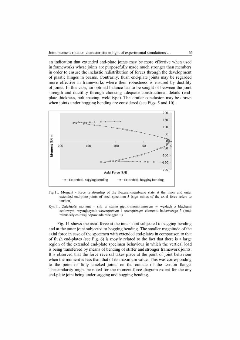
Fig.11. Moment - force relationship of the flexural-membrane state at the inner and outer
extended end-plate joints of steel specimen 3 (sign minus of the axial force refers to tension)
Rys.11. Zależność moment – siła w stanie giętno-membranowym w węzłach z blachami czołowymi wystającymi: wewnętrznym i zewnętrznym elementu badawczego 3 (znak minus siły osiowej odpowiada rozciąganiu)
Fig. 11 shows the axial force at the inner joint subjected to sagging bending
and at the outer joint subjected to hogging bending. The smaller magnitude of the axial force in case of the specimen with extended end-plates in comparison to that of flush end-plates (see Fig. 6) is mostly related to the fact that there is a large region of the extended end-plate specimen behaviour in which the vertical load is being transferred by means of bending of stiffer and stronger framework joints. It is observed that the force reversal takes place at the point of joint behaviour when the moment is less than that of its maximum value. This was corresponding to the point of fully cracked joints on the outside of the tension flange. The similarity might be noted for the moment-force diagram extent for the any end-plate joint being under sagging and hogging bending.

66 M. A. Giżejowski, A. Szwed, A. A. K. Saleh, W. Barcewicz
3.3. Composite steel-concrete specimen with flush end-plate joints
In this section, selected results of global and local behaviour of composite specimen 2 with flush end-plate joints are presented. Firstly, the results of global behaviour in terms of framework load-displacement characteristic are presented.
135 kN
165 mm
-50
0
50
100
150
0 50 100 150 200 250 300 350
Load
[kN
]
Displacement [mm]
Fig. 12. Global characteristics of specimen 2: a) load - incremental step no., b) load – displacement
Fig. 12. Globalna charakterystyka elementu 2: a) siła – numer przyrostu, b) siła - przemieszczenie
Fig. 12 illustrates the behaviour of specimen 2 with composite flush end-plate joints. The first stage indicated by the vertical line in Fig. 12b shows the stage of the service load when the internal column is supported and hanged by the jack arm. The successive loading of the specimen by concrete blocks is represented in Fig. 12a by an inclined curve consisting of a zigzag line the pieces of which represent two successive steps of laying down stages of concrete blocks. First was done in one span leading to an asymmetric loading

Joint moment-rotation characteristic in light of experimental simulations … 67
pattern and the next one - in the other span, leading to restoring the symmetrical loading pattern. The first stage of loading caused a vertical reaction in the internal column equal to 135.6 kN. At this stage, first signs of cracking in the concrete slab were observed in the vicinity of the outer column. The second stage of successive application of displacement increments was related to a simulation of the static column removal process. It resulted in a slow reduction in the magnitude of vertical reaction, with a continuous loss of the specimen stiffness. The joints yielded progressively, mainly by the increased plastic deformations of the steel components of inner composite joint, namely yielding of the column web, end-plates and column flange being in bending, beam flange and web in tension, and for the external composite joints - by yielding of the column web in compression and yielding of slab reinforcing bars being in tension. During this stage, the cracks in the vicinity of the external composite joints were more pronounced and yielding of some steel joint components was observed. For the internal composite joint, a separation of the end-plate was seen under sagging moment and the fracture was observed more clearly around the bottom bolts row. The concrete cracks in the vicinity of external composite joints continued to enlarge and yielding appeared in rebars followed by yielding of steel components in the compression zone. The most important phenomenon to be mentioned is the crushing of the concrete in the inner composite joint (axis C in Fig. 1).The maximum vertical force recorded in the hydraulic jack was reached at an instantaneous static equilibrium that was in response to the vertical displacement of 165 mm. This state was however associated with the rapid progression of end-plate fracture tearing and concrete crushing close to the internal column, and with the drop in the magnitude of reactive force. As a result, the permanent static equilibrium could not be reached in the stress redistribution process. Failure of the frame was caused by progressive cracking in the joint end-plates near welds connecting them to the beam bottom flange, and also by yielding of reinforcing steel bars in the external joints. The longitudinal rebars in the external composite joints were progressively more stressed, the concrete there more cracked under tension and concrete at the internal joint was progressively crushed. At the latter point, further yielding was developed in the different components of composite joints. Illustration of successive states of internal joint deformations is presented in Fig. 13. The state 1 corresponds to the initial configuration, state 2 to the final state of the 1st stage of loading, and the following states are referred to the 2nd stage of loading program.

68 M. A. Giżejowski, A. Szwed, A. A. K. Saleh, W. Barcewicz
Fig. 13. Illustration of successive deformation states of internal column joint Rys. 13. Ilustracja kolejnych etapów deformacji węzła przy słupie wewnętrznym
Fig.14. Details of joint components deformation; a) crushing of concrete slab of inner joint,
b) fracture of end-plate of inner joint, c) cracking of concrete slab of outer joint Rys.14. Szczegóły deformacji części składowych węzła; a) kruszenie płyty betonowej węzła
wewnętrznego, b) zniszczenie blachy czołowej węzła wewnętrznego, c) zarysowanie płyty betonowej węzła zewnętrznego

Joint moment-rotation characteristic in light of experimental simulations … 69
The final stage is referred to the specimen collapse indicated by large deformations of an extensively cracked end-plate of the inner composite joint and a substantial crushing of the reinforced concrete slab. The outer joint is at a different state and the specimen failure results in this joint in yielding of rebars and large cracking of concrete. The details are shown in Fig. 14.
Fig. 15 shows the moment-rotation characteristic of the composite inner joint subjected to two stages loading program. Since the inner column was in the first loading stage hanged, the support exerted the reactive force. The joint reached the hogging moment of approximately 40 kNm at the end of the first stage of loading program. During the simulation of the static column loss scenario, the joint was subjected to reversed rotation since the incremental settlement of inner column support reduced progressively the reactive force causing the moment to change the sign from hogging to sagging bending.
Fig. 15. Local characteristics of specimen 2 at the inner joint being under hogging bending in the
first stage of loading by concrete blocks, and then reversing to sagging bending in the second stage of static column loss simulation; a) moment - incremental step no., b) moment – rotation
Rys. 15. Lokalna charakterystyka elementu 2 w wewnętrznym węźle, będącym pod wpływem ujemnego momentu zginającego w pierwszym etapie obciążenia blokami betonowymi, a następnie pod wpływem momentu dodatniego w drugim etapie, symulującym statyczną utratę słupa; a) moment – numer przyrostu, b) moment - obrót
3.4. Composite steel-concrete specimen with extended end-plate joints
In this section the behaviour of composite specimen 4 observed in experimental investigations is reported.
Fig. 16 shows the global behaviour of composite specimens 4. In the first stage of the loading program, referred to the vertical line, an increase in the vertical reactive force at the middle column is observed which was associated with a progressively increased uniformly distributed load.

70 M. A. Giżejowski, A. Szwed, A. A. K. Saleh, W. Barcewicz
The maximum value was equal to 174 kN. The specimen was still in the quasi-elastic region when the maximum reaction was reached. Then, as previously mentioned, a vertical displacement was progressively imposed until the collapse of the tested specimen. At the second stage of column loss simulation scenario, the sub-frame entered into yielding and catenary action states, with the force finally reaching the maximum absolute value on the opposite side to that for the first stage of loading. During this stage, the cracks at the outer composite joints were clearly visible with yielding and rupture of steel components of the joints observed. Fig. 17 shows the total collapse of the inner joint after the complete crushing of concrete and end-plate fracture resulting in pulling out of the beam tension flange followed by the detachment of end-plate.
174kN
565; 4
-50
0
50
100
150
200
-200 0 200 400 600
Displacement [mm]
Vert
ical
load
at j
ack
F [k
N]
Fig. 16. Global characteristics of specimen 4: a) load - incremental step no.,
b) load – displacement Rys. 16. Globalna charakterystyka elementu 4: a) siła - numer przyrostu, b) siła - przemieszczenie

Joint moment-rotation characteristic in light of experimental simulations … 71
Fig. 17. Details of the inner joint deformation at collapse, a) general view, b) concrete crushing,
c) end-plate fracture Rys. 17. Szczegóły deformacji węzła wewnętrznego przy zniszczeniu, a) widok ogólny,
b) kruszenie betonu, c) rozerwanie blachy czołowej
Referring to study presented by Barcewicz [10], it had been expected that composite flush end-plate joints would be more flexible in the first stage of loading program, i.e. under hogging bending, than those of extended end-plates. This would in turn result in a different local behaviour of inner column extended end-plate joint subjected to two stages loading program. The local behaviour of inner column composite extended end-plate joint is presented in Fig. 18. Comparing the local behaviour of flush end-plate and extended end-plate joints in the first stage of loading one can conclude that the latter one reached a lesser hogging moment at the end of first loading stage, and then a higher sagging moment at the end of the second stage of loading program.
External column joints are subjected to hogging bending in both stages of loading program. Tension of external composite joints continued causing yielding of steel components and cracking of concrete (see Fig. 19). The longitudinal reinforcing bars at the external composite joints partially failed. The reduction of joint stiffness is observed and it is linked to the loss of longitudinal reinforcing bars in the vicinity of the external joints. The stiffness of the outer joint is decreased also due to the fracture of one of the most stressed bolts as a result of bolt tension and bending.

72 M. A. Giżejowski, A. Szwed, A. A. K. Saleh, W. Barcewicz
Fig. 18. Local characteristics of specimen 4 at the inner joint being under hogging bending in the
first stage of loading by concrete blocks, and then reversing to sagging bending in the second stage of static column loss simulation; a) moment - incremental step no., b) moment – rotation
Rys. 18. Lokalna charakterystyka elementu 4 w wewnętrznym węźle, będącym pod wpływem ujemnego momentu zginającego w pierwszym etapie obciążenia blokami betonowymi, a następnie pod wpływem momentu dodatniego w drugim etapie symulującym statyczną utratę słupa; a) moment – numer przyrostu, b) moment – obrót
Fig. 19. Details of the outer joint; a) concrete cracking and separation of profiled sheeting,
b) damaged bolt, c) fractured bolt Rys. 19. Szczegóły węzła zewnętrznego; a) zarysowanie betonu i odseparowanie betonu
od blachy profilowanej, b) zniszczona śruba, c) zerwana śruba

Joint moment-rotation characteristic in light of experimental simulations … 73
The examination of the most stressed bolts after the test showed that the broken bolt had the fracture at the threaded length while the other bolt was almost fractured. Details are given in Fig. 19b,c. The test ended with only 7 bolts instead of 8 and with one of the most stressed bolt row being heavily damaged. As it was discovered later on, after the test, the nuts of failed bolts were by mistake of the lower class then required for the bolted connectors used in the joint.
The final deformation profile of composite extended end-plate specimen configuration is shown in Fig. 20. It can be seen that this configuration was associated with large displacements. Concrete blocks at this state were stably positioned along the beams of tested specimen.
Experimental investigations of global behaviour of tested specimens and local behaviour of joints were supplemented by virtual simulations of laboratory tests conducted. Finite element models were built and computer analysis was preformed with use of ABAQUS and LSDYNA commercial software [11, 12].
Fig. 20. Final deflected configuration of specimen 4 with the composite joints Rys. 20. Końcowa konfiguracja ugiętego elementu 4 z węzłami zespolonymi
4. Concluding remarks
Robust joints need to possess a balance between sufficient rotation capacity and strength in the presence of catenary action. Experiments on steel frameworks have shown that end-plate joints with flush end-plates may develop a rather high tensile force since their ductility and low strength does not allow the large displacement through the bending resistance of joints. Analogical

74 M. A. Giżejowski, A. Szwed, A. A. K. Saleh, W. Barcewicz
frameworks with composite flush end-plate joints may not be robust enough since their low strength under sagging bending, despite of good ductility proven in tests on isolated steel joints, does not allow for the redistribution of internal forces in order to achieve the equilibrium in the residual state after static column removal.
Contrary, symmetrical steel joints with extended end-plates on both sides of beam flanges seem to be more robust, despite of their lesser ductility proven in tests on isolated steel joints. Experiments on steel frameworks have shown that joints with extended end-plates develop lower tensile force since their high strength allows for the load transfer through the bending resistance of joints. Robust bending behaviour is possible because extended end-plate joints exhibit a better balance between the strength and rotation capacity that allows to achieve the equilibrium state in case of a static column loss event. The composite frameworks with extended end-plate joints may therefore transfer the gravity loads and additional loads due to the column loss scenario in modelling the capacity in residual state. The margin of residual safety is depended upon constructional details of composite joints.
Laboratory tests described in the present paper were limited to sub-frames with two types of end-plate joints having specific joint constructional details. The robustness of frameworks by joint ductility may further be enhanced by choosing optimal sizes of fillet welds, distances between the bolt rows, as well as between the welds and neighbouring bolt rows. The other factors having an impact on the joint robustness are the reinforcement ratio and the arrangement of shear studs in composite slab in the close distance to the joint. References
[1] EN 1990. Eurocode: Basis of Structural Design. [2] EN 1991-1-7. Eurocode 1: Actions on Structures, Part 1-7: Accidental Actions. [3] Robustness. Chapter 6 in: Steel Buildings in Europe - Multi-Storey Steel Buildings.
Part 4: Detailed design, http://www.arcelormittal.com/sections/index.php?id=167. [4] Demonceau J.F.: Steel and composite building frames: sway response under
conventional loading and development of membrane effects in beams further to an exceptional action. PhD Thesis, Universite de Liege, Faculte de Sciences Appliquees. Annee Academique 2007-2008.
[5] Hai L.N.N.: Structural response of steel and composite building frames further to an impact leading to the loss of a column. PhD Thesis, Universite de Liege, Faculte de Sciences Appliquees. Annee Academique 2008-2009.
[6] Menchel K.: Progressive Collapse: Comparison of Main Standards, Formulation and Validation of New Computational Procedures. PhD Thesis, Universite Libre de Bruxelles, Faculte de Sciences Appliquees. Annee Academique 2008-2009.

Joint moment-rotation characteristic in light of experimental simulations … 75
[7] Saleh A.A.K.: Modelling of beam-to-column joint of steel-concrete composite frames subjected to standard and extreme load combinations. PhD thesis, Warsaw University of Technology, Warsaw 2013 [in preparation - non-referred publication of the Warsaw University of Technology Publishing Office].
[8] Kozlowski A., Gizejowski M., Sleczka L., Pisarek Z., Saleh B.: Experimental investigations of the joint behavior – Robustness assessment of steel and steel-concrete composite frames. Proceedings of the 6th European Conference on Steel and Composite Structures, Budapest 2011, vol. A, pp. 339-344.
[9] Giżejowski M., Saleh B., Kozłowski A., Pisarek Z., Ślęczka L.: Experimental investigations of the frame behaviour subjected to exceptional actions. Zeszyty naukowe Politechniki Rzeszowskiej, seria Budownictwo i Inżynieria Środowiska, zeszyt 59, nr3/2012/II, str. 161-168 [in Polish].
[10] Barcewicz W.: Stiffness, strength and rotation capacity of a certain class of joints in steel structures with composite slabs. PhD thesis, Faculty of Civil Engineering, Warsaw University of Technology, Warsaw 2010 [in Polish – non-referred publication of the Warsaw University of Technology Publishing Office].
[11] Giżejowski M., Kwaśniewski L., Balcerzak M.: Numerical modeling of damage for a tested composite steel-concrete specimen. Proceedings of CMM-2011: Computer Methods in Mechanics. Minisymposium: Structures under Extreme Actions (organized by M. Giżejowski and L. Kwaśniewski), Warsaw, 9–12 May, 2011.
[12] Giżejowski M., Kwaśniewski L., Saleh B., Balcerzak M.: Numerical Study of Joint Behavior for Robustness Assessment. Journal of Applied Mechanics and Materials, Vols. 166-169, 2012, 3114-3117 [doi:10.4028/www.scientific.net/AMM.166-169.3114].
CHARAKTERYSTYKA MOMENT-OBRÓT WĘZŁÓW W ŚWIETLE BADAŃ DOŚWIADCZALNYCH SYMULUJĄCYCH UTRATĘ NOŚNOŚCI SŁUPA RAMY S t r e s z c z e n i e
W pracy rozważano zagadnienia odporności na zagrożenie katastrofą postępującą stalowych konstrukcji ramowych z podatnymi węzłami stalowymi i zespolonymi stalowo-betonowymi. Przeprowadzono badania doświadczalne podukładów ramowych w skali naturalnej. Badania dotyczyły zachowania się węzłów ram stalowych pod wpływem oddziaływania wymuszonego przemieszczeniem, symulującego zdolność węzłów do przeniesienia obciążeń przez zginanie z udziałem sił rozciągających pojawiających się w wyniku utraty nośności słupa ramy. Badania doświadczalne ram z węzłami zespolonymi stalowo-betonowymi przeprowadzono w dwóch etapach. Etap pierwszy dotyczył zachowania się podukładu w stanie użytkowania poprzedzającym zdarzenie wyjątkowe, gdy słup pełnił rolę elementu nośnego, stropy zaś były obciążone kombinacją oddziaływań grawitacyjnych stałego i trwałej części użytkowego. W drugim etapie, podukład z obciążeniem grawitacyjnym jak w etapie pierwszym poddano oddziaływaniom wymuszonym przemieszczeniem słupa symulującym statyczną utratę jego nośności. Na podstawie badań stwierdzono, że zespolone węzły ze zlicowanymi blachami czołowymi nie są wystarczająco odporne na postępującą katastrofę ze względu na niską wytrzymałość przy zginaniu momentem dodatnim i mimo dobrej ciągliwości, nie pozwalają na redystrybucję sił wewnętrznych po statycznej utracie słupa. Natomiast węzły stalowe

76 M. A. Giżejowski, A. Szwed, A. A. K. Saleh, W. Barcewicz
i zespolone z symetrycznie wystającą blachą czołową wykazują zadowalający poziom odporności na katastrofę postępującą, mimo niższej ciągliwości. Węzły te wykazują lepszy balans pomiędzy nośnością a zdolnością do obrotu, który pozwala uzyskać stan równowagi w przypadku utraty słupa.
Słowa kluczowe: węzeł stalowy, węzeł zespolony, badania podukładu ramowego, utrata słupa, ciągliwość węzła, odporność na zagrożenie katastrofą postępującą
DOI: 10.7862/rb.2013.17 Przesłano do redakcji: w czerwcu 2013 r. Przyjęto do druku: w lipcu 2013 r.


![Śruby, podkładki, wkręty | technika zamocowań | Azmet Radom · 2017-06-23 · 39,26 460 Characteristic capacity 3,78 4,56 Characteristic yield moment [Nmm] 2 075 2 787 21 20,63](https://static.fdocuments.in/doc/165x107/5f4f9462d34b1b6e3847d52a/ruby-podkadki-wkrty-technika-zamocowa-azmet-2017-06-23-3926-460.jpg)