Johnson Controls - Fire Detection - ANZ Region · Welcome to this fifth edition of the Johnson...
134
Fire Detection Product Catalogue Australia Issue 5
Transcript of Johnson Controls - Fire Detection - ANZ Region · Welcome to this fifth edition of the Johnson...

Fire Detection Product Catalogue Australia Issue 5

Page ii
Copyright © 2019 Johnson Controls. All rights reserved. Unauthorised use of trademarks is strictly prohibited. Printed February 2019.Tyco Australia Group Pty Limited. A.B.N. 93076836416, a Johnson Controls company.
w w w . v i g i l a n t -f i r e . c o m . a u

Page 1
Fire Detection Product Catalogue
w w w . s i m p l e x - f i r e . c o m . a u
We aim to make our product range as comprehensive as possible to ensure you never need to go anywhere else. To meet this goal, our product specialists, with your help, have selected the most appropriate, cost effective product range available. Only those products that meet the highest quality criteria have been included.
Our National Distribution Centre, located in Sydney, is one of the largest Fire & Security product distribution centres in Australia. Our goal is to despatch products on the same day we receive your order before 2:00 pm.
Our warranty and service returns policy is located towards the back of this catalogue - look for “Warranty Procedure” on page 124 for your reference. We recognise that your business is highly dependant on reliable products. All our Johnson Controls manufactured products are backed by a 24 months warranty. A purchase order and Return Authorisation (contact Customer Service) is required for parts to be replaced under warranty.
Welcome to this fifth edition of the Johnson Controls Fire Detection Product Catalogue for Australia.
For all enquiries regarding this catalogue, please contact Johnson Controls Customer ServiceTelephone: 1300 725 688Facsimile: 1300 720 733Email: [email protected]
For Technical Support, please contact Johnson Controls Technical ServicesTelephone: 1300 552 559
Introduction

Page 2
Fire Detection Product Catalogue
w w w . v i g i l a n t -f i r e . c o m . a u
VIGILANT Non-Addressable Fire Indicator Panels
VIGILANT Non-Addressable Detectors
VIGILANT Non-Addressable Detector Bases
Non-Addressable Manual Call Points
VIGILANT Addressable Fire Indicator Panels
MX Functional Detector Bases
VIGILANT Responders
Series 130Addressable Modules40
SIMPLEX High Level Interface48
51
Detector Accessories and Remote Indicators58
VIGILANT 19in RackCabinets
62
Looms and Cables66
5
7
9
10
12
20
27
MX Addressable Modules22
TrueAlarm Addressable Detectors
53
38 Series 130Addressable Detectors
SIMPLEX Fire Indicator Panels42
Fire Panel Ancillaries60
MX Addressable Detectors16
MAPNET II/IDNet Addressable Devices

Page 3
Fire Detection Product Catalogue
w w w . s i m p l e x - f i r e . c o m . a u
Warning Systems — Audio Devices
Batteries and Power Supply Units
Warning Systems — Visual Devices
86
AS1668 Control and Gas Control
VIGILANT Remote Annunciators
VIGILANT QE90 EWIS Panel
EWIS Ancillaries
Warning System Generators
Audio Visual Indicators90
91
Door Holders and Accessories93
VESDA Aspirating Smoke Detectors95
Flame & Special Hazard Detection102
Beam Smoke & Linear Heat Detection
Detector Test Equipment112
84
69
71
74
75
80
EWIS Spares78
CCU Networking72
108
Page 4
Fire Detection Product Catalogue
w w w . v i g i l a n t -f i r e . c o m . a u
Table of Contents5 Conventional (Non-Addressable) Fire Indicator Panels7 Conventional Detectors - VIGILANT 614 Series9 Conventional Detector Bases10 Conventional Manual Call Points12 Addressable Fire Indicator Panels16 MX TECHNOLOGY Analogue Addressable Detectors20 Functional Detector Bases22 MX TECHNOLOGY Analogue Addressable Modules27 MX4428 Responders38 Analogue Addressable 130 Series Detectors40 Analogue Addressable 130 Series Modules42 SIMPLEX 4100ESi System Overview45 Addressable Loop Cards - MX & IDNet48 SIMPLEX High Level Interface49 SIMPLEX 4100 Network Systems51 TrueAlarm Addressable Detectors53 SIMPLEX Addressable MAPNET II Modules54 SIMPLEX Addressable MAPNET II/IDNet Modules55 SIMPLEX Addressable IDNet Modules58 Detector Accessories & Remote Indicators60 Fire Panel Ancillaries62 VIGILANT 19inch Rack Cabinet Range66 Looms and Cables69 AS1668 Controls and Gas Controls71 VIGILANT Remote Annunciators72 CCU Networking74 Warning Systems77 QE90 Ancillaries & Spares80 Warning System Generators84 Warning System Ancillaries90 Audio Visual Indicators (AVI)91 Batteries and Power Supplies93 Door Holders & Accessories95 Aspirating Smoke Detectors VESDA102 Flame and Special Hazard Detectors 103 Intrinsically Safe - MX Analogue Addressable Detectors106 Intrinsically Safe - Conventional (Non-Addressable) Detectors108 Intrinsically Safe Isolators/Barriers108 Beam Smoke and Linear Heat Detectors112 Detector Test Equipment114 Hazardous Area Classification115 International Protection Ratings116 Symbols118 Reference Tables118 Conventional (non-addresable) Detector Selection Chart119 MX Detector Selection Chart119 VIGILANT/Minerva Sounder Base Selection Guide120 Spare Parts List124 Warranty Procedure125 QE90 EWIS Panel Configuration126 Index129 Product Index130 Terms and Conditions

Page 5
Fire Detection Product Catalogue
w w w . s i m p l e x - f i r e . c o m . a u
The 8 zone F3200 will suit small installations requiring a system up to 8 detection circuits and provides all the features of the existing F3200 Fire Indicator Panel (FIP) range.
This panel is a replacement for the F08 FIP. It is a compact, self-contained panel which performs the functions of the Control and Indicating Equipment (CIE), as specified by the Australian Standard AS 4428.1 Fire Detection, Control and Intercom Systems - Control and Indicating Equipment.
The 8 zone F3200 offers features including: -
• AS4428 Firefighter Facility• LCD Display • Flexible programmable logic equations • Event logging to history file • Networking capabilities - up to 250 panels (with MX1 as MFIP)• Eight zones fitted• Standard 3A Power Supply to power a T-GEN 50 • Battery capacity 2x17Ah
Operation is straightforward with the F3200’s keypad and alphanumeric LCD. The 40 character, 2 line LCD zone control panel meets the AS 4428.1 “Firefighter Facility” (FF) requirements. “Next” and “Prev” keys allow easy scrolling through the 99 event alarm buffer, while all current alarms, faults and isolated zones can be separately displayed.
ActivFire Listed: afp-789
Remote Annunciators, refer to Page 71
The F3200 is a self-contained, modular, microprocessor based FIP which performs the functions of the CIE as specified by AS 4428. It has a high degree of flexibility and expandability, catering for medium to very large buildings.
A single panel has 8 zones fitted as standard, and can have up to 64 zones. A network system may have up to 64 panels. The F3200 can be fitted with 64 zone LEDs and supports AS 1668 fan controls and gas release.
The F3200 detector circuit electronics caters for a wide range of detectors, It also caters for interfacing to Intrinsically safe circuit barriers/isolators (hazardous areas), long line circuits e.g. from a sub-indicator FIP and tamper-proof circuits. Typically the 15U cabinet has space to accommodate up to 40Ah battery capacity. The ActivFire Listings are: afp-789 (VIGILANT), afp-1421 (Simplex).
F3200 8 Zone F3200 8 - 64 Zone
Conventional (Non-Addressable) Fire Indicator Panels
PhysicalCabinet Dimensions (HWD)FP0780 15U - 750 x 550 x 211 mmWeight 25kgFP0784 8U - 440 x 550 x 211 mmWeight 17kgIP Rating IP30
Part NumbersPanel:FP0784 8 zones fitted (max.) 3A PSU, 8U Cabinet (batteries not included)ManualsLT0250 F3200 Operator’s ManualLT0255 F3200 Installation and Configuration ManualLT0256 F3200 Programming Manual
Part NumbersBlank Panels - (includes 19” rack fixing hardware)FZ9002 7U Blank Hinged Inner Door (312mm)FZ9003 6U Blank Panel Acrylic (267mm)FZ9004 4U Blank Panel (178mm)FZ9005 3U Blank Panel (134mm)FZ9006 2U Blank Panel (89mm)FZ9007 1U Blank Panel (45mm)FZ9015 5U Blank Panel (223mm)FZ9016 6U Blank Panel (267mm)
Cabinets - Refer to Page 62
Part NumbersPanelFP0780 8 zones fitted 24 zone capacity, no cardframe 3A PSU, 15U CabinetFP0781 8 zones fitted 64 zone capacity, incl. cardframe 3A PSU, 15U Cab’tFP0782 8 zones fitted 24 zone capacity, no cardframe 6A PSU, 15U CabinetFP0783 8 zones fitted 64 zone capacity, incl. cardframe 6A PSU, 15U Cab’tManualsLT0250 F3200 Operator’s ManualLT0121 F3200 Technical ManualLT0255 F3200 Installation & Configuration ManualLT0256 F3200 Programming ManualLT0130 F3200 Presentation Drawings (AutoCAD)LT0135 F3200 Architect’s Specification A4OptionsFP0553 8 zone input expansion kit (incl.PA0492, LM0053, 8xEOLR)FP0554 8 relay expansion kit (incl. PA0493, LM0053, 8x MiniJump Links)FP0795 Network upgrade kit (AS4428) {incl. IC0358,SF0222,LT0330,PA0773,LM0091}FP0749 3A to 6A PSU Upgrade Kit (AS1603)FP0779 3A to 6A PSU Upgrade Kit (AS4428)FP1002 MX1 style Display Extender Kit (incl. FP1002, LM0291, LM0339)FZ3031 FP0475 Disp. Extender Kit incl 1.2m FRC. Use as first (LHS) Display.FZ9028 3U WA/Cube ASE Bracket & LoomFP0475 Display Extender kit (incl PA0454, LM0046 FRC, not for 1st display)KT0072 Cardframe upgrade kitKT0199 3U Centaur ASE BracketKT0274 F3200 AS1603 to AS4428 U/G Kit (incl.ME0098,LM0092,SF0423)KT0429 F3200/NDU Upgrade to V5.xx SoftwareME0457 MX1 style 4U Display Door, 5x16 Zone, requires FP1002
LED Displays - Refer to Page 61Spares - Refer to Page 120

Page 6
Fire Detection Product Catalogue
w w w . v i g i l a n t -f i r e . c o m . a u
The F3200 Single Zone (single risk) Gas Control Panel is designed to meet the CIE requirements of AS 4214-2002, “Gaseous Fire Extinguishing Systems”. It includes all circuits and relays normally required for single zone gas control panels. When coupled with the AVI Mk2 warning signs and FP0570/2 Local Gas Control Stations it provides a cost-effective, easily programmed single zone gaseous fire extinguishing system. FP0876 is an F3200 in an 8U cabinet (FP0784) complete with an ME0442 1 zone, 1U gas control module pre-wired to the 8 zone module and an 8 relay module.
FP0877 is based on a 6 Amp power supply F3200 assembled into the standard 15U cabinet (FP0782). It comes complete with an ME0442 1 zone, 1U gas control module pre-wired to the 8 zone module and an 8 relay module.
Gas Control Stations - refer to page 70Warning Signs - refer to page 90
SpecificationsDimensionsFP0876 8U - 440 x 550 x 211mm (HWD)FP0877 15U - 750 x 550 x 211mm (HWD)Part NumbersFP0876 F3200 AS4428 8U, 3A PSU, 1U Gas Ctrl, Pre Prog. (shown at left)FP0877 F3200 AS4428 15U, 6A PSU 1U Gas Ctrl Pre Prog.
FP0876 8U Panel with 3A PSU
F3200 Single Zone Gas Control Panel
F3200 Expansion Kits
PA0874, F3200 AS4428 MAF/PSU 6A 1931-3-3 Size: 160 x 250 x 45 mm, 400g
PA0873, F3200 AS4428 MAF/PSU 3A 1931-3-3 Size: 160 x 250 x 45 mm, 400g
FP0554, F3200 8 Relay Expansion KitIncludes: PA0493 8 Relay Module, LM0053 FRC, 8 x Minijump links (for supervision selection). Size: 195 x 125 x 12mm 250g
FP0553, F3200 8 Zone Input Expansion KitIncludes: PA0492, 8 Zone Module, LM0053 FRC, 8 x EOLR (std). (EOL = 2k7 5% 0.4W).Size: 195 x 125 x 12mm, 220g
KT0072 F3200 Cardframe Upgrade KitA KT0072 Cardframe upgrade kit can be fitted to a 15U F3200 to allow it to take more than three 8 way modules. The KT0072 cardframe can accommodate 8 F3200 modules (for MX4428:- 8 ADR or 6 MPR/MXP/ADR+RRM). In older versions, the cardframe mounts directly to the rear of the cabinet. In newer versions, the cardframe is fitted to a gear plate that may be removed when the cabinet is mounted to the wall.
Part NumbersKT0072 F3200 Cardframe Upgrade Kit
F3200 Spares
Part NumbersKT0072 F3200 Cardframe Upgrade Kit (see below)FP0553 F3200 8 Zone Input Expansion Kit FP0554 F3200 8 Relay Expansion KitFP0749 F3200 AS1603.4 PSU Upgrade Kit 3A to 6AFP0779 F3200 AS 4428.1 PSU Upgrade Kit 3A to 6APA0873 F3200 AS4428 MAF/PSU 3A 1931-3-3PA0874 F3200 AS4428 MAF/PSU 6A 1931-3-3
For a comprehensive list of spares, refer to page 120

Page 7
Fire Detection Product Catalogue
w w w . s i m p l e x - f i r e . c o m . a u
The 614CH fire detector provides very early warning of slow smouldering fires. The CO fire detector is well suited to many applications where heat detection is insufficient but smoke detection causes unwanted alarms. As CO travels more freely than smoke, the positioning of CO fire detectors is more flexible. This feature is particularly useful in large complex structures such as atria and warehouses, where positioning of smoke detectors is difficult. The 614CH has an additional mode of operation as a Class A1R combined rate-of-rise and 60°C fixed temperature heat detector to supplement the CO detector mode to permit the detector to react to a wider range of fire types. Although the 614CH has a rated service life of 10 years, in order for the 614CH to provide the intended level of fire detection, the detector should be checked for calibration 5 years after installation (or 5 years after re-installation following service) or within 7 years of the date of manufacture.
614CH Carbon Monoxide and Heat Fire Detector
The 614P is capable of detecting the visible smoke produced by materials which smoulder or burn slowly, i.e. soft furnishings, plastic foam etc. or ‘smoke’ produced by overheated but unburnt PVC. These detectors are particularly suitable for general applications and areas where cable overheating may occur; electrical services areas. The novel design of the asymmetrical sampling chamber and signal processing techniques stop unwanted alarms caused by very small insects. Smoke entering the sampling chamber scatters the infrared light pulses onto a photodiode. These pulses are converted to an electrical signal that is compared against a preset alarm level.
614P Photoelectric Smoke Detector
The 614I detectors are offered for legacy specifications which still call for ionisation smoke detectors. The 614I offers detection of visible and invisible fire aerosols (products of combustion) and is therefore capable of detecting the early presence of hot smouldering and flaming fires, such as wood, paper etc. They use a dual ionisation chamber in which the air is ionised by a single radioactive source. The presence of smoke in the sampling chamber causes a change in the balance voltage between the two chambers. This is then compared against an alarm level.Use of ionisation chamber smoke detectors is not recommended for new installations.
614I Ion Chamber Smoke Detector
SpecificationsOperating Voltage 10 to 33VdcQuiescent Current 55µA (max.)Alarm Current1 3.2 to 67mA (50°C)Alarm State Voltage 2.5 to 7.4VdcAlarm Threshold 38ppm COExt. Powered Load (max.) 50mA, 28VdcRemote Indicator E500 Mk2 SeriesRelative Humidity 15 to 90% (n/cond)Ambient Temp 0 to +50°CDimensions (incl. base) 127 dia x 54H (mm)Weight 200g with baseActivFire Listed afp-1718FPANZ Listed VF/345Part Number 516.600.3041. 3.2mA min. for LED visibility. Max. current must be externally
limited
SpecificationsOperating Voltage 10 to 33VdcQuiescent Current 60µAAlarm Current (max.)* 0.7 to 67mA (55°C) 0.7 to 60mA (70°C)Alarm State Voltage 2.5 to 7.4VExt. Powered Load (max.) 50mA. 28VdcSensitivity (AS7240.7-2004) 4%Obs/mRemote Indicator E500 Mk2 SeriesRelative Humidity 10% to 95% (n/cond)Ambient Temperature -20°C to +70°CDimensions (incl. base) 127 dia x 54H (mm)Weight 188g with baseActivFire Listed afp-1715FPANZ Listed VF/344Part Number 516.600.301*Max. current must be externally limited
SpecificationsOperating Voltage 12 to 33VdcQuiescent Current 70µAAlarm Current* 0.7 to 67mA (55°C) 0.7 to 60mA (70°C)Alarm State Voltage 2.5 to 7.4VExt. Powered Load (max.) 50mA, 28VdcIonisation Source <33kBq (Am241)Alarm Threshold 0.32 MIC XRemote Indicator E500 Mk2 SeriesRelative Humidity 10% to 95% (n/cond)Ambient Temperature -20°C to +70°CDimensions (incl. base) 127 dia x 54H (mm)Weight 200g with baseActivFire Listed afp-1716FPANZ Listed VF/343Part Number 516.600.305*3.2mA min. for LED visibility. Max. current must be externally
limited
Conventional Detectors - VIGILANT 614 SeriesThe VIGILANT 614 range of low profile non-addressable detectors have a number of unique design features that offer improved operation, installation and ease of servicing. Through innovative design, these detectors have reduced the installation and servicing time to a minimum. The VIGILANT 614 range includes the 614CH Carbon Monoxide fire detector, which responds to carbonaceous fires with an unprecedented early detection of slow smouldering fires, yet offers unequalled false alarm immunity.
The use of the patented optical sensing chamber, together with refined signal processing, has enabled the introduction of a smoke detector suitable for fast, reliable smoke detection of both slow and fast developing fires.The VIGILANT 614 series is compatible with conventional (non-addressable) circuits on VIGILANT F3200, and addressable panels using suitable interface modules on MX1, MX4428, 4100ESi.
Features• Range includes unique CO+Heat fire detector• Type A, B, C and D Heat detector• Low profile and discreet• Superior performance and reliability• Patented optical chamber• Attractive design• Designed for fast, easy installation• Detector Lock included with 4B base• Integral and remote alarm LED• ActivFire and FPANZ Listing

Page 8
Fire Detection Product Catalogue
w w w . v i g i l a n t -f i r e . c o m . a u
VIGILANT 614T heat detectors use a fast response, thermistor based design. The fixed temperature sensing thermistor readily tracks the local ambient temperature, thus quickly, accurately and consistently identifying when a fixed temperature is exceeded. Rate-of-rise detection is achieved by comparing the response of two thermistors, with one having a slower thermal response. By combining accurate thermistors with proper physical placement, this patented rate-of-rise detection design achieves a high level of heat detection performance.
614T Heat DetectorSpecificationsOperating Voltage 11 to 32VdcQuiescent Current 1 85µA @ 24Vdc (typ.)Alarm Current 2 5mA to 80mAAlarm State Voltage 3 3.0V to 12.4VRemote Indicator E500 Mk2 SeriesRelative Humidity 10% to 95% (n/cond)Ambient Temperature Types A, B -10°C to +45°C Types C, D -10°C to +75°CStorage Temperature -20°C to +75°CDimensions (mm) 127 dia x 53H Weight 174g with 5B base
1. Max. quiescent 110μA. 2. Min. 5mA for LED visibility; max. current must be externally limited. 3. Min. voltage with remote indicator shorted @ 5mA. Max @ 80mA without remote indicator connected.
ActivFirePart Number Model Type Listed4098-9637EA 614TA Type A afp-18134098-9638EA 614TB Type B afp-18144098-9639EA 614TC Type C afp-18154098-9640EA 614TD Type D afp-1816
D515B Duct Sampling UnitThe D515B Duct Sampling Unit consists of a D51B duct housing fitted with a 4B base suitable for fitting a non-addressable 614P photoelectric smoke detector. The D51B is designed to sample air in air conditioning ducts and pass the air through the smoke detector. The housing is fixed on the outside of the duct to be sampled, allowing easy access for detector servicing and replacement of the dust filter. To cater for most duct sizes, a sampling tube extension is available in 3 metre lengths. VIGILANT E500 Mk2 Series Remote Indicators can be used for remote indication of an alarm. The D515B with 614P can be used with F3200 CIE logic for non-latching operation. The D515B with VIGILANT 614P is compatible with non-addresable alarm zone circuits on VIGILANT and SIMPLEX CIE.
SpecificationsDuct Pressure* -1.15 to +3.0 kPa Sampling Tube Length 160mm minimumMax. Duct Width 1.8mRemote Indicator E500 Mk2 Series Dimensions Base & Cover (LWH) 278x190x113 mm Fixed Tube Length 160 mm below base Sampling Tube Pitch 122mm Duct Holes Required 24mm dia. x 2 placesNot ActivFire ListedPart NumbersD515B D51 c/w 4B base**D51COVER D51 Cover only c/w screwsD51L Baffle box of 10 D51F Filter box of 10 D51T3 3m Sampling TubeD51K100 Sampling Tube End Cap pkt of 10*AS 1603.13-1998 test **Wired for collective base
885WP-B IP67 Heat DetectorThe 885WP-B is a 2 wire fixed temperature Type B heat detector. This detector is designed to provide open area protection in areas subject to moisture. It is sealed against the entry of moisture to a rating of IP67. The LED will latch on when the detector is in alarm. Detectors are used with a mounting base that permits mounting directly on to a 50mm or 60mm junction box. The 885WP-B includes a tamper-resistant feature that prevents its removal from the mounting base without the use of a key. Flying leads are provided for termination:- 2 Black (negative), 2 Red (positive), 2 White (positive Remote LED).
SpecificationsOperating Voltage 8.5 to 30VdcQuiescent Current < 50µAAlarm Current (min.) 2mA @ 3.1VdcAlarm Current (max.) 80mA @ 6.5VdcMax. Air Velocity 20m/sAlarm Temperature 63°C (fixed temp.)Ambient Temperature -15°C to +50°CDimensions (mm) 102 dia x 48H Weight 170g with baseIngress Protection IP67ActivFire Listing afp-1778Part Number 885WP-B
Conventional Detectors - VIGILANT 614 Series

Page 9
Fire Detection Product Catalogue
w w w . s i m p l e x - f i r e . c o m . a u
4B Universal Base
Ceiling Tile Adaptor
The 4B Universal Base contains no electronics and is suitable for indoor applications of the 614 series conventional (non-addressable), 814 and 850 series analogue addressable detectors. It provides excellent space for cable access and terminations. It features remote LED connections and an anti-tamper facility. The 4B base is designed to snap-fit into the ceiling tile adaptor, or screw fix to the ceiling in the traditional manner.The Euro Mount Adaptor is a shallow (20mm deep) back box for surface mounting applications. The 4B-6A Adaptor covers ceiling marks revealed when changing from an existing 5” or 6” base.
The Ceiling Tile Adaptor (CTA) is used to prepare a ceiling tile to be able to accept a complete base and detector assembly. It comprises a Bezel (1), Clamp (2) and Back Box (3). Traditionally the detector base is installed without the detector head, as mounting screws must be inserted through the back plate of the base. The CTA can save time by allowing a system to be installed and commissioned before the ceiling is installed. Once the ceiling is installed the base and detector assembly can be pulled into place without the need for disassembly and re-testing.
Conventional Detector Bases
SpecificationsOperating Temp. -25°C to +75°CRelative Humidity 10% to 95% (non cond.)Dimensions (mm) 109 dia x 25HWeight 64gActivFire Listed with compatible detectorsPart Numbers517.050.041 4B Base517.050.052 Euro Mount Adaptor517.050.056 4B-6A 4” to 6” Adaptor
SpecificationsDimensions (H x Dia) 52 x 165 mmWeight 232gCeiling Cutout 127mm (30mm max. tile)Material Flame Retardant ABSColour WhiteAmbient Temperature –25°C to +70°CStorage Temperature –40°C to +80°CRelative Humidity 10% to 95% (non cond.)Part Numbers517.050.060 Ceiling Tile Adaptor Kit - 517.050.056 Back Box - 517.050.057 Bezel and Clamp517.050.058 CTA-AP Ceiling Tile Sounder Base Adaptor Plate (8x111 dia. not shown)
4B-DHM Deckhead MountingThe Deckhead Mounting can be used with VIGILANT 600/800 Series detectors using 4B base when fitted in particularly damp or dirty environments. Only suitable detectors should be used - consult bulletin GPBD0018. The housing has four 20/25mm cable breakouts and is secured with two countersunk screws at 128.5mm fixing centres. The mounting surface should be flat over the area of the underside of the housing to ensure a stable fixing and strong enough to take the weight of the mounting, detector base and sensor. Extra Base Accessory Terminals (BATs) are available (one is supplied).
SpecificationsAmbient Temperature -25°C to +70°CRelative Humidity up to 95% (non cond.)Dimensions (mm) 115 dia x 42H (147.5 W overall)Weight 200gProtection IP55 c/w supplied gasketPart Numbers517.050.051 4B-DHM517.050.612 BAT Kit - pack of 10 (available on request)
A simple Volume Adjustment Tool, specific to the task of sounder volume selection on the “variable-volume” range of VIGILANT MKII Sounder Base Devices. Sounder volume can be easily varied using this simple, functional tool.
Volume Adjustment ToolPart Number517.050.015 Volume Adjustment Tool
The 601SB Sounder Base provides a sounder function on conventional fire detection circuits. It operates independently of the detector circuit and may be used without an associated detector. When used without a detector, a sounder base cap should be fitted to cover the exposed terminals. The 601SB requires an external 24V dc supply and provides eight tones including the ISO8201 T3 evacuation signal. It is identified by a green temporary park plunger. Refer to Sounder Base Applications table for further details.
601SB Sounder BaseSpecificationsOperating Voltage 18 to 32VdcAlarm State Current 1.2mA @ 68dBA (low vol) 6.8mA @ 90dBA (max vol)Ambient Temperature -25°C to +70°CRelative Humidity 10% to 95% (non cond.)Dimensions (mm) 108 dia x 38HWeight 195gWire Size 1.5mm2 to 2.5mm2
Not ActivFire ListedPart Numbers577.001.035 601SB557.001.040 Sounder Base Cap
(1) (2) (3)

Page 10
Fire Detection Product Catalogue
w w w . v i g i l a n t -f i r e . c o m . a u
Conventional Manual Call PointsSU0631 Manual Call Point
The SU0631 Manual Call Point is supplied with one normally open and one normally closed contact. Selecting either the “Normally Open” or “Normally Closed” contact is easily achieved by simply connecting the terminal block to the required connection in the back of the MCP. Single pole changeover switching can be achieved with the use of two terminal blocks. The call point is operated when the frangible glass element is snapped, releasing the MCP’s micro switch, which signals an alarm to the fire panel. The Call Point and Backbox are ordered separately. Unless stated the VIGILANT indoor manual call points are supplied as flush mount units. The VIGILANT range are approved for use with the standard backbox if surface mounting is required.
SpecificationsMax. Operating Voltage 30VdcMax. Switch Current 2ACable Termination 0.5 to 2.5 mm2
Relative Humidity 0 to 95% (non/cond)Ambient Temperature -10°C to +55°CDimensions (HWD) 93x89x60mmWeight 110g (flush)Ingress Protection IP24DActivFire Listed afp-3239Part Numbers SU0631 Manual Call PointSU0632 Red BackboxSC070 Spare Test Keys (pkt10)515.001.025 Spare Glass (pkt 5)
SU0634 IP67 Waterproof Call PointSpecificationsOperating Voltage 30Vdc (max.)Switch Current 2A @ 30Vdc (max.)Cable Termination 0.5mm2 to 2.5mm2
Dimensions (HWD) 93x98x76 mmWeight 270gAmbient Temperature -30°C to +70°CRelative Humidity up to 95% (non-cond.)Ingress Protection IP67Not ActivFire listed by Johnson ControlsPart NumbersSU0634 IP67 Manual Call Point515.001.025 Spare Glass (pk 5)SC070 Spare Test Keys (pkt10)
This surface mounting Manual Call Point has an Ingress Protection rating of IP67, making it suitable for wet area applications. The callpoint is operated by simply pressing on the centre of the frangible element until it snaps, which releases a microswitch, signaling an alarm at the CIE. A plastic coated frangible element ensures safe and reliable operation, and does not produce dangerous glass shards. The SU0634 is supplied with one normally - open and one normally - closed contact. Selecting either configuration is achieved by locating the terminal block on the appropriate connection. Single pole change-over switching can be achieved using two terminal blocks.
Manual Call Point Accessories
Part NumberSU0615 Transparent hinged cover to suit all SUxxx call points (MCP not included) Material LEXAN241 polycarbonate.
Part Number 515.001.043 This polycarbonate breakglass keybox is available to protect emergency keys
Part Number SC070 Packet of ten Test keys for VIGILANT MCPs
SpecificationsDims (mm) 75W x 40H typicalPart NumbersSU0603 Spare glass VIGILANT (Pkt 10) white text on black backgroundSU0605 Spare glass WORMALD (Pkt 10) white text on black backgroundSU0609 Spare glass Black pictogram on white background (Pkt 10)515.001.025 Spare glass no logo (Pkt 5) clear text on white background515.001.127 Flexible plastic element
Part NumberSR3T-P Red surface mounting back box (for
indoor callpoints) with terminals fitted.
SpecificationsAmbient Temperature -10°C to +55°CDimensions (HWD) 86 sq x 32 mmPart Numbers SU0632 Red Backbox

Page 11
Fire Detection Product Catalogue
w w w . s i m p l e x - f i r e . c o m . a u
Weather STOPPER Weather STOPPER II
Specifications STI6535 STI3150Dims (HWD) 210x137x57.5 254x178x86Call Point Size 100x100x57.5 160x160x120Ingress Protect’n Equivalent to IP44 when mounted on a smooth surface
Part Numbers
515.001.035 STI3120 Weather Stopper II515.001.036 STI6535 Weather Stopper515.001.033 IP036 Break Seal KitSTI-13120FR STI3120 Surface fit Weather STOPPER with sounder
IP036 Break Seal Kit
STI3150 Weather STOPPER IISTI6535 Weather STOPPER
The callpoint STOPPER provides protection from malicious or accidental activation of manual callpoints. Available for flush or surface mounted callpoints the ‘STOPPER’ is also available with optional high pitch sounder which is activated when the lid is lifted. An optional ‘Break-Seal’ fitting kit allows ‘Break-Seals’ to be used to provide extra protection.
The Weather STOPPER II extends the life of weather exposed callpoints, by offering protection against harsh conditions and environments, e.g, oil rigs and ship decks. While offering environmental protection the Weather STOPPER II is constructed from polycarbonate which will also guard against tampering or accidental operation of devices.
STOPPER IIA 70 mmB 16 mmC 197 mmD 50 mmE 178 mmF 146 mmG 228 mmH 254 mmMax. MCP 160 sq. x 120 mm
STOPPERA 137 mmB 140 mmC 104 mmD 45 mmE 12.5 mmF 12.5 mmG 185 mmH 12.5 mmMax. MCP 100 sq. x 57.5 mm (+30 mm Surface)
WEATHER STOPPER MODEL COMPARISON
STOPPER STOPPER II With Sounder Weatherproof
Product Code Ref Flush Surface
515.001.029 STI6530
515.001.030 STI6531
515.001.036 STI6535
515.001.034 STI1230
515.001.035 STI3150
515.001.031 STI6532
STI-13120FR STI-13120FR
Weather STOPPER Weather STOPPER II

Page 12
Fire Detection Product Catalogue
w w w . v i g i l a n t -f i r e . c o m . a u
Addressable Fire Indicator Panels
Specifications 15U Cabinet 8U CabinetMaterial Mild SteelFinish Powdercoated Titania RippleDims (HWD) 750x550x211 440x550x211 mmWeight 25kg 17kgIP Rating IP30 IP30
Remote Fire Brigade Panel (FP0991) Material Mild Steel Finish Powdercoated cream wrinkle finish Dims (HWD) 220x380x56 mm Surface mnt 220x380x21 mm Flush mnt Weight 3.8kg IP Rating IP30Part NumbersFP0927 MX1 15U 3U ASE bracketFP0928 MX1 15U 3U WA/Cube ASE bktFP0948 MX1 15U 3U BlankFP1040 MX1 8U 3U BlankFP1030 MX1 15U Empty Cab c/w WindowFP0950 MX1 Loop Card KitFP1002 LED Disp Ext kit (incl. LM0291,LM0339)FP0991 MX1 Remote Fire Brigade PanelFP0996 MX1 4U 19in Rack Mounting Remote Fire Brigade PanelFP1031 MX1 15U, Empty Cabinet, Blank Door, TitaniaFP1121 T-Gen2 3U Grade 3 User Interface incl. T-Gen 60 Amp and mic.FP1056 MX1 3U 12-way AS 1668 Fan Control ModuleFP1057 MX1 2-way AS 1668 Cntrl Bd ExpLM0076 Programming Cable DB9F-DB9F Null ModemME0457 4U Door 5xFP1002 LED Disp BrdFA2515 Door Lock Catch/Switch BracketLED Displays - Refer to Page 61Spares - Refer to Page 121
MX1 utilises MX VIRTUAL multi-sensor analogue addressable detectors with dual sensors (photoelectric and heat, or CO and heat) to allow the best detection mode for a situation to be easily selected.
Detection modes may include: smoke/ CO detection only, heat-enhanced smoke/ CO detection only, smoke/ CO plus heat detection, heat-enhanced smoke/ CO plus heat detection or heat detection only.
Heat detection can be either fixed temperature, or combined fixed temperature and rate-of-rise.
For specific applications, single-sensor MX analogue addressable ionisation and photoelectric smoke detectors, high sensitivity smoke detectors (VESDA), heat-only detectors and flame detectors are also available.
The MX DIGITAL communications protocol used on the detection loop is designed to provide high reliability and fault resistance, with operation possible over many cable types.
This often permits system upgrades using existing cable. The loop configuration ensures that communications continues in the event of a loop open circuit fault condition.
In the case of a short circuit, up to 100 short circuit isolator detector bases or modules may be fitted around the loop, to limit the effect of the fault to the devices between isolators.
MX1 is now available as a custom-built Gas Control panel. Contact your local Johnson Controls Fire Detection representative for information.
• Single MX DIGITAL Loop supporting up to 250 MX devices
• Add up to 7 optional MX DIGITAL loop cards for a total of 2000 MX devices
• Network up to 250 MX1* panels over fibre, copper or ethernet
• MX DIGITAL multi-sensor analogue addressable detector technology
• Field-proven fire detection algorithms
• Bi-directional IR communication with 850 Series Gen6 detectors
• Clear alarm messages on 4-line LCD
• Compact zone LED display
• High level EWIS interface
• Up to 126 AS 1668 Fan Controls
• “Profiles” simplify programming of complex detection and logic functions
• Day/Night modes for alarm sensitivity adjustment and output logic functions
• Powerful, field-programmable logic equations, functions, timers
• Pseudo points controlled by logic equations for enhanced control options
• Built-in clock/ calendar with automatic daylight saving adjustment
• Comprehensive test facilities including automatic self-test and fast commissioning test mode
• High capacity integral 5A power supply
• 19” Rack Cabinet
• Earth fault supervision
• Fuse supervision
• Windows-based programming tools
*With MX1 as the main FIP, a network of up 250 panels (MX1 / MX4428 / F3200) can be connected on the same system.
The VIGILANT MX1 is an innovative, networkable multiple loop analogue addressable fire indicator panel incorporating the latest technology. It complies with AS 7240.2:2004, AS 7240.4:2004, AS 4428.3:2010 and the functional requirements of AS 4428.10:1998 and AS 4428.7:1999. Its support for MX TECHNOLOGY fuzzy-logic detection algorithms and powerful control functions make it suitable for a wide range of fire protection applications, including those in hazardous areas.
ApprovalsMX1 is certified to AS 7240.2:2004, AS 7240.4:2004: “Fire detection and alarm systems”, AS 4428.3:2010: “Fire detection, warning, control and intercom systems - Control and indicating equipment - Fire brigade panel” AS 4428.10:1998: “Fire detection, warning, Control and intercom systems - Alarm investigation” ActivFire Listing Number afp-2320
MX1 15U Note: Optional 3U ASE bracket, 3U T-Gen 60 Grade 3 User
Interface, and 3U AS1668 Fan Control bracket shown fitted
MX1 8U MX1 Remote Fire Brigade Panel (surface mount)
MX1 Fire Alarm System
Page 13
Fire Detection Product Catalogue
w w w . s i m p l e x - f i r e . c o m . a u
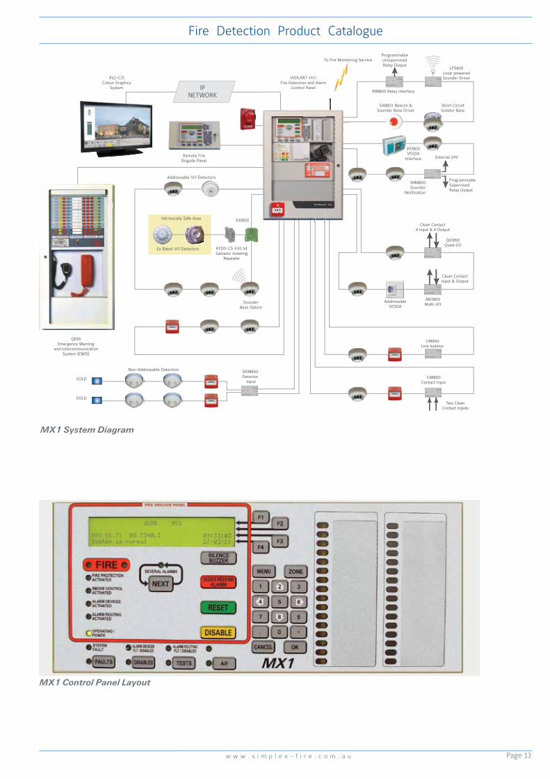
MX1 System Diagram
MX1 Control Panel Layout
IPNETWORK
Two Clean Contact Inputs
VIGILANT MX1 Fire Detection and Alarm
Control Panel
Clean ContactInput & Output
QIO850Quad-I/O
RIM800 Relay Interface
External 24V
ProgrammableSupervisedRelay Output
SNM800Sounder
Notification
DDM800Detector
Input
ProgrammableUnsupervisedRelay Output
LPS800Loop-poweredSounder Driver
SAB801 Beacon &Sounder Base Driver
Short CircuitIsolator Base
Remote Fire Brigade Panel
XLG-C/SColour Graphics
System
QE90Emergency Warning
and Intercommunication System (EWIS)
VIO800VESDA
Interface
Intrinsically Safe Area
Ex Rated MX Detectors
Addressable MX Detectors
Non-Addressable Detection
EXI800
EOLD
KFD0-CS-EX1.54Galvanic Isolating
Repeater
AddressableVESDA
SounderBase Option
MIO800Multi-I/O
Clean Contact4 Input & 4 Output
LIM800Line Isolator
To Fire Monitoring Service
EOLD
CIM800Contact Input
Page 14
Fire Detection Product Catalogue
w w w . v i g i l a n t -f i r e . c o m . a u
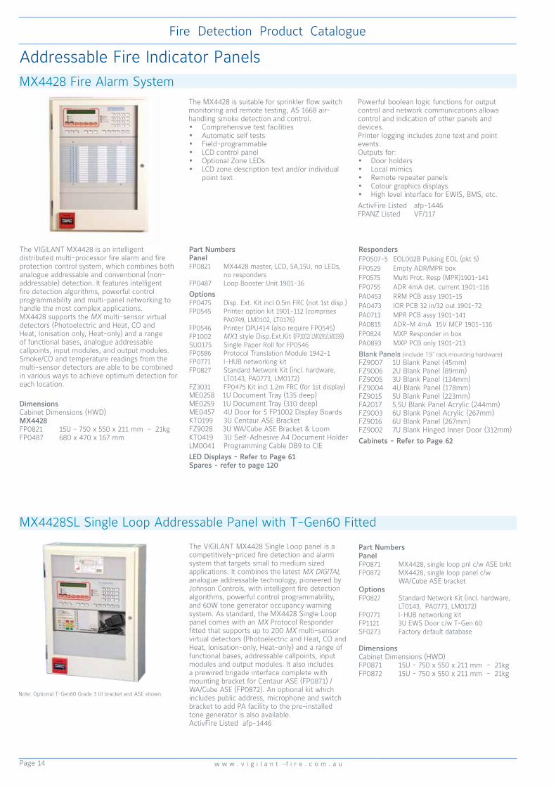
The VIGILANT MX4428 is an intelligent distributed multi-processor fire alarm and fire protection control system, which combines both analogue addressable and conventional (non-addressable) detection. It features intelligent fire detection algorithms, powerful control programmability and multi-panel networking to handle the most complex applications. MX4428 supports the MX multi-sensor virtual detectors (Photoelectric and Heat, CO and Heat, Ionisation only, Heat-only) and a range of functional bases, analogue addressable callpoints, input modules, and output modules. Smoke/CO and temperature readings from the multi-sensor detectors are able to be combined in various ways to achieve optimum detection for each location.
The MX4428 is suitable for sprinkler flow switch monitoring and remote testing, AS 1668 air-handling smoke detection and control.• Comprehensive test facilities• Automatic self tests• Field-programmable • LCD control panel • Optional Zone LEDs• LCD zone description text and/or individual
point text
Powerful boolean logic functions for output control and network communications allows control and indication of other panels and devices.Printer logging includes zone text and point events.Outputs for: • Door holders• Local mimics• Remote repeater panels• Colour graphics displays• High level interface for EWIS, BMS, etc.ActivFire Listed afp-1446FPANZ Listed VF/117
MX4428 Fire Alarm System
The VIGILANT MX4428 Single Loop panel is a competitively-priced fire detection and alarm system that targets small to medium sized applications. It combines the latest MX DIGITAL analogue addressable technology, pioneered by Johnson Controls, with intelligent fire detection algorithms, powerful control programmability, and 60W tone generator occupancy warning system. As standard, the MX4428 Single Loop panel comes with an MX Protocol Responder fitted that supports up to 200 MX multi-sensor virtual detectors (Photoelectric and Heat, CO and Heat, Ionisation-only, Heat-only) and a range of functional bases, addressable callpoints, input modules and output modules. It also includes a prewired brigade interface complete with mounting bracket for Centaur ASE (FP0871) / WA/Cube ASE (FP0872). An optional kit which includes public address, microphone and switch bracket to add PA facility to the pre-installed tone generator is also available. ActivFire Listed afp-1446
MX4428SL Single Loop Addressable Panel with T-Gen60 Fitted
Addressable Fire Indicator Panels
DimensionsCabinet Dimensions (HWD)MX4428FP0821 15U - 750 x 550 x 211 mm - 21kgFP0487 680 x 470 x 167 mm
Part NumbersPanelFP0871 MX4428, single loop pnl c/w ASE brktFP0872 MX4428, single loop panel c/w WA/Cube ASE bracketOptionsFP0827 Standard Network Kit (incl. hardware, LT0143, PA0773, LM0172)FP0771 I-HUB networking kitFP1121 3U EWS Door c/w T-Gen 60SF0273 Factory default database
DimensionsCabinet Dimensions (HWD)FP0871 15U - 750 x 550 x 211 mm - 21kgFP0872 15U - 750 x 550 x 211 mm - 21kg
RespondersFP0507-5 EOL002B Pulsing EOL (pkt 5)FP0529 Empty ADR/MPR boxFP0575 Multi Prot. Resp (MPR)1901-141FP0755 ADR 4mA det. current 1901-116PA0453 RRM PCB assy 1901-15PA0473 IOR PCB 32 in/32 out 1901-72PA0713 MPR PCB assy 1901-141PA0815 ADR-M 4mA 15V MCP 1901-116FP0824 MXP Responder in boxPA0893 MXP PCB only 1901-213
Blank Panels (include 19” rack mounting hardware)FZ9007 1U Blank Panel (45mm)FZ9006 2U Blank Panel (89mm)FZ9005 3U Blank Panel (134mm)FZ9004 4U Blank Panel (178mm)FZ9015 5U Blank Panel (223mm)FA2017 5.5U Blank Panel Acrylic (244mm)FZ9003 6U Blank Panel Acrylic (267mm)FZ9016 6U Blank Panel (267mm)FZ9002 7U Blank Hinged Inner Door (312mm)Cabinets - Refer to Page 62
Part NumbersPanelFP0821 MX4428 master, LCD, 5A,15U, no LEDs, no respondersFP0487 Loop Booster Unit 1901-36
OptionsFP0475 Disp. Ext. Kit incl 0.5m FRC (not 1st disp.)FP0545 Printer option kit 1901-112 (comprises PA0749, LM0102, LT0176)FP0546 Printer DPU414 (also require FP0545)FP1002 MX1 style Disp.Ext.Kit (FP1002/ LM0291/LM0339)SU0175 Single Paper Roll for FP0546FP0586 Protocol Translation Module 1942-1FP0771 I-HUB networking kitFP0827 Standard Network Kit (incl. hardware, LT0143, PA0773, LM0172)FZ3031 FP0475 Kit incl 1.2m FRC (for 1st display)ME0258 1U Document Tray (135 deep)ME0259 1U Document Tray (310 deep)ME0457 4U Door for 5 FP1002 Display BoardsKT0199 3U Centaur ASE BracketFZ9028 3U WA/Cube ASE Bracket & LoomKT0419 3U Self-Adhesive A4 Document HolderLM0041 Programming Cable DB9 to CIELED Displays - Refer to Page 61Spares - refer to page 120
Note: Optional T-Gen60 Grade 3 UI bracket and ASE shown

Page 15
Fire Detection Product Catalogue
w w w . s i m p l e x - f i r e . c o m . a u
NetworkConnection to other systems
Air-Handling and Plant
Equipment LoopBoosterSupply
32 Input/32 OutputResponder (IOR)
or4 Input/ 4 Output
Responder (ADR/ARR)
32 Input/32 OutputResponder (IOR)
or4 Input/ 4 Output
Responder (ADR/ARR)
Responder Communications LoopUp to 127 RespondersFully ProtectedCommunications and Power
Optional Zone LEDIndications
Ancillary Outputs
Monitoring Service
Logging Printer
Diagnostics andProgramming
AS 1668Fire Fan
Control Panel
MX ProtocolResponder
(MXP)
MX ProtocolResponder
(MXP)
MX DIGITAL Analogue Addressable LoopUp to 200 Devices
MX DIGITAL Analogue Addressable LoopUp to 200 Devices
Remote Operation
Status
ProgrammableControl Outputs
Status Indications
ManualControls
Short CircuitIsolator Base
Short CircuitIsolator Base
End of LineResistor Conventional Detector
Circuit
Conventional DetectorInput
External 24V
External 24V
Sounder Base
ProgrammableSupervised
Relay Output
ProgrammableRelay Output
Relay BaseClean Contact
Output
CleanContact
Input
Short CircuitIsolator Base
Short CircuitIsolator Base
Short CircuitIsolator Base
Short CircuitIsolator Base
MX AddressableManual Call Point
Analogue Addressable Detectors
Analogue Addressable Detectors
ProgrammableControlOutputsInputs Inputs
ControlBatteries
MainsNetworkconnection to other CIE, FIP, EWIS etc
Colour Graphics
High LevelInterface
Repeater Panels(up to 8)
Emergency Warning and Intercommunication
System (EWIS)
WarningSystem
MX4428 MasterFire Indicator Panel
ExternalStrobe
Individual Zone Alarms
Building Management
and/or AS1668 Control
Systems with Vigilant IO-NET
MX FASTLOGIC
MX4428 System Diagram
Responder Loop DesignCentral to the MX4428 system is the proven “Responder Loop” architecture, which allows intelligent responders to be either distributed at selected locations around the protected premises, or located centrally at the FIP. Analogue addressable loop wiring and other inputs and outputs are terminated at these responders, which in turn are connected by the 4-wire responder loop to the FIP.The responder loop is fully protected: a partial or complete break, or short, anywhere on the loop is detected and isolated automatically at the adjacent responders. All system operations are fully maintained even in the presence of the fault condition. This design offers many benefits:• Cable concentration at the master FIP is greatly reduced.• Installed cost is lower because the loop design requires less wiring than conventional methods.• Compatibility with many existing conventional and analogue addressable systems, providing a ready upgrade path.• Ideal suitability as a main panel upgrade with old sub-panels connecting via responder inputs.• High-integrity communications is fully supervised and protected by redundant paths.• Loop fault sensing and isolation is provided at every responder.• Intelligent diagnostics identifies location of faults rapidly.• Expansion and alterations are easily accommodated with minimal additional wiring.• Responder Loop Boosters permit virtually unlimited loop length.• No additional multicore wiring is required for AS 1668 controls, but optional use of dedicated IO-NET (PLC) system is also possible.
Detection AlgorithmsSMARTSENSE is a field-proven, reliable detection algorithm, providing unwanted alarm reduction, compensation for ambient conditions and a wide range of programmable sensitivity settings.MX FASTLOGIC is a “fuzzy logic” based algorithm applied to photoelectric smoke and heat enhanced smoke detection, and designed to differentiate between the smoke and temperature patterns of real fires and typical causes of unwanted alarms .Both algorithms provide:• Detector pre-alarm sensing for early warning of a potential alarm.• Compensation for soiling and changes in ambient conditions.• Logging “detector dirty alert” when compensation limits are about to be exceeded, to
allow maintenance to be scheduled.• Heat sensor can be programmed to act independently as a Heat Detector
MX4428 Rack Cabinet SpecificationsCabinet Size 15U 18U 21U 28U 40UNumber of extender inner doors: Master 1 2 2 3 3
Extender 2 2 3 4 4Maximum number of LED displays: Master 64 128 128 192 192
Extender 128 128 192 256 256Spare space at bottom: Master 4U 0U 3U 3U 15U
Extender 1U 4U 0U 0U 12UStandard size gear plates (max.): 1 1 1 2 3Overall Height (mm): 750 885 1050 1330 1865Overall Width (mm): 550 575 575 575 575Overall Depth (mm): 211(176 int.) 205/380 350(310 int.) 205/380 205/380 (135 or 310 internal)Cabinet Material: 1.2mm M.S. 1.6mm M.S. 1.6mm M.S. 1.6mm M.S. 1.6mm M.S.Cabinet Finish: Baked epoxy powdercoat, Cream Wrinkle BFF998CW

Page 16
Fire Detection Product Catalogue
w w w . v i g i l a n t -f i r e . c o m . a u
MX TECHNOLOGY Analogue Addressable Detectors
The 850P is a state-of-the-art smoke detector using a photoelectric sensor which, in conjunction with the MX fire alarm panel, suits most fire detection applications. The 850P incorporates a unique “mousehole” design optical chamber with superior signal to noise ratio providing high resilience to dust and dirt which means reduced service costs. In addition a unique chamber cover actually draws slow moving smoke into the chamber to provide a more responsive detector. A stainless steel insect screen is used on the 850P to provide a high degree of immunity to small insects. Use with MX1, MX4428, 4100ESi.
850P Smoke Detector
SpecificationsOperating Voltage 20 to 40VdcQuiescent Current 330µA (typ.)Ambient Temperature -25°C to +70°CRelative Humidity 10% to 95% (non-cond)Dimensions 109 dia x 43H mm Weight 76gActivFire Listed afp-2928FPANZ Listed VF/362Part Number 516.850.052.E
With its ability to detect a wide range of fires from flaming to smouldering types, the 850PH combined smoke and heat multi-sensor detector is the preferred choice for a range of applications including industrial, retail and office environments. It can operate in a number of approved modes and sensitivities that can be dynamically selected to suit different environmental conditions. The heat sensor monitors rate-of-rise and fixed temperature and has been tested as a fire detector in its own right. Use with MX1, MX4428, 4100ESi.
850PH Multi-Sensor Smoke and Heat Detector
850H Heat DetectorThe 850H is a flexible cost-effective addressable heat detector with most of the features of MX VIRTUAL detectors. The 850H reports the temperature to the MX fire alarm panel which allows various detection modes. The 850H uses a high quality thermistor with very low thermal mass. This allows the detector to function as a heat detector as well as providing a fast and accurate temperature display. Use with MX1, MX4428, 4100ESi.
SpecificationsOperating Voltage 20 to 40VdcQuiescent Current 330µA (typ.)Ambient Temperature -25°C to +70°CRelative Humidity 10% to 95% (non-cond)Dimensions 109 dia x 43H mm Weight 76gActivFire Listed afp-2930FPANZ Listed VF/363Part Number 516.850.051.E
SpecificationsOperating Voltage 20 to 40VdcQuiescent Current 290µA (typ.)Ambient Temperature -25°C to +70°CRelative Humidity 10% to 95% (non-cond.)Dimensions 109 dia x 43H mm Weight 81gActivFire Listed afp-2927FPANZ Listed VF/218Part Number 516.850.053.E
For life protection and when the environmental conditions are challenging, the 850PC combined heat/smoke/CO fire detector provides the ultimate in detector performance and false alarm rejection. Outputs from multiple sensors are combined to accurately determine the presence of fire. Applications include residential, industrial, retail, transport hubs, and healthcare. Its false alarm rejection properties make it the ideal choice for hotel bedrooms where steam from bathrooms is a common source of false alarms. Use with MX1, MX4428, 4100ESi.
850PC Multi-Sensor Carbon Monoxide, Smoke and Heat Detector SpecificationsOperating Voltage 20 to 40VdcQuiescent Current 370µA (typ.)Ambient Temperature -10°C to +55°CRelative Humidity 15% to 90% (non-cond.)Dimensions 109 dia x 43H mm Weight 94gActivFire Listed afp-2929FPANZ Listed VF/367Part Number 516.850.054

Page 17
Fire Detection Product Catalogue
w w w . s i m p l e x - f i r e . c o m . a u
The D51MX consists of a D51 duct sampling housing fitted with a 4B base wired to suit an MX analogue addressable 850P/814P or 850PH/814PH photoelectric smoke detector. When fitted with the detector the DSU is designed to sample air in air conditioning ducts and pass the air through the smoke detector. The D51MX is fitted on the outside of the duct to be sampled allowing easy access for detector servicing and replacement of the dust filters. To cater for most duct sizes, a sampling tube extension is available in 3 metre lengths. The VIGILANT E500 Mk2 Series Remote Indicators can be used for remote indication of an alarm. Use with MX1, MX4428, 4100ESi.
D51MX Duct Sampling UnitSpecificationsOperating Voltage 20 to 40VdcQuiescent Current 275µA (typ.)Alarm Current 10mA with LED onDuct Pressure1 -1.15 to +3.0 kPa Duct air velocity foralarm at 8%Obs/m1 1, 2, 4, 8m/sSampling Tube Length 160mm minimum Max. Duct Width 1.8mRemote Indicator E500 Mk2 Series Dimensions Base & Cover (LWH) 278x190x113 mm Sampling Tube Pitch 122mm Duct Holes Required 24mm dia. x 2 plcsAmbient Temp -10°C to +55°CRelative Humidity 10% to 95% (n/cond)ActivFire Listed2 afp-1496
1. AS 1603.13-1998 test 2. Listed with 814PH
801F Flame Detector
VLC-800MX LaserCOMPACTThe VLC-800MX LaserCOMPACT detector has been specifically designed to provide all the benefits of aspirating smoke detection, including very early warning, in single small areas and where space is a premium. The VLC-800MX communicates directly with the MX4428 CIE via the MX loop detecting smoke by using proven VESDA aspirating technology, dual stage filtration technology in combination with the versatility of the MX4428 CIE. The VLC-800MX utilises a standard VESDA pipe design in accordance with the Aspire design tool.Refer to the VESDA section for accessories. Use with MX1, MX4428.
SpecificationsExternal Supply 18 to 30VdcQuiescent Current 225mAAlarm Current 245mAAmbient Temp Sensor Ambient -10°C to +39°C Sampled Air -20°C to +60°CRelative Humidity 10% to 95% (n/cond)Alarm Sensitivity 0.005 to 20%Obs/mCoverage Area 800 m2Dimensions (HWD) 225x225x85mmWeight 1.9 kgActivFire Listed afp-1580FPANZ Listed VF/341Part Number VLC-800MX
Part NumbersD51MX Duct Sampling UnitD51L Baffle box of 10D51F Filter box of 10D51T3 3m Sampling TubeD51K100 Sampling Tube End Cap (pkt of 10)
The 801F point type flame detector presents a cost-effective solution to providing nuisance alarm free flame detection for indoor applications. The 801F is a full featured solar blind flame detector for indoor use and boasts a high degree of false alarm immunity. The 801F is designed for direct connection to the MX digital loop, employing the same universal detector base or functional base as the 850 series fire detectors. An intrinsically safe version is also available. Use with MX1.
SpecificationsOperating Voltage 20 to 40VdcQuiescent Current 300µA (typ.)Range1 0.4m2 n-heptane at 50m Field of View 100oAmbient Temperature -20°C to +70°CRelative Humidity 10% to 95% (non-cond)Dimensions 109 dia x 22H mm Weight 110gNot ActivFire ListedFPANZ Listed VF/354Part Number 516.800.0061. Distance measured on axis

Page 18
Fire Detection Product Catalogue
w w w . v i g i l a n t -f i r e . c o m . a u
The MCP820 Addressable Manual Call Point is suitable for indoor applications. As supplied, it is suitable for flush mounting. A surface mounting back box is available separately. The MCP820 is designed to monitor and signal the condition of the switch contact that is operated by breaking a plastic coated glass frangible element (flexible plastic option available). Any change in the status of the switch is immediately communicated to the Control and Indicating Equipment (CIE). The MCP820 has an integral short-circuit isolator for protecting the addressable loop wiring. Use with MX1, MX4428.
The CP820 is an alternative MX addressable call point which does not have an integral short circuit isolator. Use with MX1, MX4428, 4100ESi.
MCP820 Addressable Call PointSpecificationsOperating Voltage 20 to 40VdcQuiescent Current 275µA (max.)Alarm Current 2.8mA (max. LED on)Indoor Applications OnlyRelative Humidity 10% to 95% (n/cond)Ambient Temperature -25°C to +70°CDimensions (HWD) 87x87x52 mmWeight 170gIngress Protection IP24DActivFire Listed afp-1503 (CP820) afp-2874 (MCP820)Part NumbersCP820 CP820 only514.800.611 MCP820 onlySU0632 Backbox515.001.025 Spare Glass (pkt 5)
The MXP Loop Filter board is available for fitting to an MXP in order to further improve common-mode interference suppression that may occur as a result of the MXP detector loop not being adequately separated from power wiring, lift motors etc. Use with MX1, MX4428, 4100ESi.
MX Loop Filter (Interference Suppression)
SpecificationsOperating Supply 20 to 40VdcDimensions (HWD) 70x20x25mmPart Number PA1038
The MCP830 Addressable surface mounting Manual Call Point has an International Protection rating of IP67, making it suitable for outdoor applications. It is designed to monitor and signal the condition of the switch contact that is operated by breaking a plastic coated frangible glass element (flexible plastic option available). Any change in the status of the switch is immediately communicated to the Control and Indicating Equipment (CIE). The MCP830 has an integral short-circuit isolator for protecting the addressable loop wiring. Note MCP830 does not have a formal UV exposure rating. Installation in full sun should be avoided.The CP830 is an alternative IP67 MX addressable call point which does not have an integral short circuit isolator. Use with MX1, MX4428.
MCP830 Addressable Waterproof Call Point
SpecificationsOperating Voltage 20 to 40VdcQuiescent Current 275µA (max.)Alarm Current 2.8mA (max. LED on)Indoor Applications OnlyRelative Humidity 10% to 95% (n/cond)Ambient Temperature -25°C to +70°CDimensions (HWD) 93x98x73 mmWeight 240gIngress Protection IP67ActivFire Listed afp-2798 (CP830) afp-2875 (MCP830)Part Numbers514.800.604.Y CP830 & Backbox514.800.612 MCP830 & B’box515.001.119 Spare Glass (pkt 5)

Page 19
Fire Detection Product Catalogue
w w w . s i m p l e x - f i r e . c o m . a u
The MX Loop Tester can test, commission and fault-find a loop of up to 250 MX digital addressable detectors/devices, without a fire panel. A laptop is generally used for operation & display, but a “One Person Installation Mode” is automatically enabled on power up. The MX Loop Tester identifies all devices on the loop, determining addresses and types. Over-addressed (>250), unknown device types, and, generally, duplicate addressed devices are recognised. Monitors analogue values of all detectors/modules on the loop to determine device status: normal/alarm/fault/dirty etc.
Provides alarm test for detectors that support it. The MX Loop Tester allows Walk Test. Any device going into alarm is shown on the laptop with address and time. Walk Test Status (devices not tested yet) can be requested. Walk test mode overrides detection algorithm delays for fast testing.The MX Loop Tester monitors loop current and status, identifying open / short and over-current conditions and can detail devices present on each side of break (so that position of break or tripped isolator can be determined).The MX Loop Tester includes commands to operate device LED and control output modules (relays and sounders), and can turn on LED of faulty detectors (when there is no alarm) to aid visual identification.Automatic addressing mode allows un-programmed devices to be added in sequence and be automatically addressed. Detailed diagnostics and commissioning modes are accessed via laptop PC. Use with MX1, MX4428.
MX Loop Tester
SpecificationsPower Source 24V batteries or 230VAC to 24V/3A plug packDimensions1 (HWD) 220x122x46mmDimensions2 (HWD) 250x250x70mmWeight 3 2kgPart Numbers4 FP0898 Aus/NZ versionSU0256 90-264VAC to 24Vdc Adaptor Plug Pack
1. Unit only 2. Carry Bag 3. Excluding batteries
4. FP0898 includes test unit, carry bag, 230VAC plug pack,
manual and loom.
The 800 Series detectors incorporate a feature which automatically transfers the address flag to the detector base when the detector is plugged into the base. On removal of the detector the address flag remains on the ceiling, thus helping to ensure that detectors are not accidentally returned to the wrong detector base following service routines. Address flags are supplied in packs of 100. Labels are provided on sheets of 250 in four colours to enable quick identification between different loops.
Address Flag
Part Numbers516.800.915 MX Address flags (pk of 100)516.800.931 Address flag lbl Loop A - Wht516.800.932 Address flag lbl Loop B - Yel 516.800.933 Address flag lbl Loop C - Ppl 516.800.934 Address flag lbl Loop D - Grn
The 850EMT is used to program the address into MX addressable devices. When used with VIGILANT MX1 systems, the 850EMT can also remotely interrogate, address and test 850 Series detectors via a two-way infrared link. It also displays information and performs tests on devices. It has a touch screen backlit colour LCD and four ‘softkeys’, ESC, OK, Up and Down. Power for the 850EMT is derived from 6 AA size NiMH rechargeable batteries. It may be run from an unregulated +12Vdc input i.e., car power outlet or 110/230VAC mains adaptor, both of which will recharge the batteries as well. The 850EMTK consists of the following:
• 850EMT MX Service Tool• Ancillary programming lead & spare pins• 6 x rechargeable AA size NiMH batteries• 240VAC Adaptor plus Lead• 12Vdc car adaptor• Hard Carry Case
Use with MX1, MX4428, 4100ESi.
850EMT MX Engineering Management Tool
SpecificationsBatteries 6xAA NiMHBatt. Operating Time up to 15 hoursAmbient Temp 0 to +50°CRelative Humidity 10% to 90% (n/cond)Dimensions1 (HWD) 50 x 210 x 125mmWeight1 600g incl. batteriesPart Numbers 850EMTK Service Tool Kit516.800.922 Ancillary Lead516.800.923 Carry Case & Acc (345 x 310 x 85 mm)516.800.924 Ancillary Lead Spare Pins
1. For 850EMT unit only

Page 20
Fire Detection Product Catalogue
w w w . v i g i l a n t -f i r e . c o m . a u
The 4B-C Continuity Base is used for most installations involving 850 Series detectors, as it allows the detector’s in-built short circuit isolation function to be in-circuit when the detector is fitted and ensures continuity is maintained when the detector is removed. Use with MX1, 4100ESi.
The 4B-I Isolator Base serves as both a base for an 814 or 850 Series MX detector and a protection device against loop short circuits, monitoring the voltage on the MX addressable loop. When a short circuit is detected, the 4B-I isolates the affected section whilst allowing the rest of the addressable loop to function normally. If a detector fitted to the 4B-I exhibits a short circuit, the 4B-I will isolate both sides of the loop from the faulty device without affecting any other device on the loop. An amber LED indicator on the rim of the base illuminates whenever the short circuit isolator is activated. The 4B-I can accommodate one of the MX detectors, or serve as a base for an 814RB. Use with MX1, MX4428, 4100ESi.
4B-C Continuity Base
4B-I Isolator Base
SpecificationsAmbient Temperature -25°C to +70°CRelative Humidity 10% to 95% (n/cond)Dimensions (mm) 109 dia x 25HWeight 64gIndoor Applications OnlyActivFire Listed with MX detectorsPart Number 517.050.0421. Maximum number of devices between 5BI bases is limited to
40 for AS 1670.1-2004 systems.
SpecificationsOperating Voltage 20 to 40VdcQuiescent Current 80µA (max.)Tripped Current 3.5mA (max.)IB Units betwn 4B-I bases 100 (max.)1Indoor Applications OnlyAmbient Temperature -25°C to +70°CRelative Humidity 10% to 95% (n/cond)ActivFire Listed with MX detectorsFPANZ Listed VF/650Part Number 517.050.0431. Maximum number of devices between 4BI bases is limited to
40 for AS 1670.1-2004 systems.
Standard Detector Bases
Functional Detector Bases
4B Universal Base
The 4B Universal Base contains no electronics and is suitable for indoor applications of the 614 series conventional (non-addressable), 814 and 850 series analogue addressable detectors.
It provides excellent space for cable access and terminations. It features remote LED connections and an anti-tamper facility. The 4B base is designed to snap-fit into the ceiling tile adaptor, or screw fix to the ceiling in the traditional manner.The 4B-6A Adaptor covers ceiling marks revealed when changing from an existing 5” or 6” base.The Euro Mount Adaptor is a shallow (20mm deep) back box for surface mounting applications.When (suitable) detectors are fitted in damp or dirty environments, the 4B-DHM Deckhead Mounting provides an IP55 seal between the mount and the detector base. Use with MX4428.
800 Series Functional Detector Bases supplement the standard universal detector base, providing sounder, relay, and loop isolation functions for the range of MX CIE. Changes to a building can easily be adapted to by retrofitting sounders and relays to existing points. Refer to Page 119 Sounder Base Selection Guide.
SpecificationsOperating Temp. -25°C to +75°CRelative Humidity 10% to 95% (non cond.)Dimensions (mm) 109 dia x 25HWeight 64gIndoor Applications OnlyActivFire Listed with compatible detectorsPart Numbers517.050.041 4B Base517.050.052 Euro Mount Adaptor517.050.056 4B-6A 4” to 6” Adaptor517.050.051 4B-DHM DeckHead Mounting Kit

Page 21
Fire Detection Product Catalogue
w w w . s i m p l e x - f i r e . c o m . a u
The 814RB Addressable Relay Base provides two sets of changeover volt-free relay contacts capable of switching 1A (resistive) @30Vdc. The relay function is controlled by the MX fire alarm panel via the detector fitted to the 814RB. The 814RB may be mounted to the ceiling, plugged into an M614/5B Universal Base or an 5BI/814IB Isolator Base. Use with MX1, MX4428.
814RB Relay BaseSpecificationsOperating Voltage 20 to 40VdcQuiescent Current 50µA (max.)Switching Current 1A @ 30Vdc max.Indoor Applications OnlyAmbient Temperature -10°C to +55°CRelative Humidity 10% to 95% (n/cond)ActivFire Listed with MX detectorsFPANZ Listed VF/638Part Number 814RB
The 802SB/901SB Addressable Sounder Bases provide a sounder function on MX addressable systems. Designed for indoor use, they require an associated detector in order to operate, as each base is controlled by its detector. The detector must be locked onto the sounder base using the detector locking device. Removal of the detector or loss of power to the loop will cause the sounder to cease sounding. It must be fixed to a flat ceiling or a suitable electrical backbox with 50mm fixing centres. The loop powered 802SB is identified by a white park clip. Up to fifty1 802SBs per loop may be operated at full volume at any one time. The 901SB requires an external 24Vdc supply and is identified by a blue park clip. The 802SB/901SB supports ISO8201 T3 tones. Use with MX1, MX4428, 4100ESi.
The AVBase sounder beacon base and high output sounder base provide a loop powered visual warning solution in addition to the normal fire alarm sounder. Reflective Sound Monitoring is employed to monitor the output of the sounder. A fault is latched at the panel should either the sounder or the beacon fails to operate. Both bases feature an in-built short circuit line isolator, reducing the modules required, thus reducing the installed cost of the system. As a single point of installation for isolator, base, detector, and sounder base, installation costs are reduced and wiring simplified. The sounder base has four volume settngs from 60 to 90dB, and 15 tone options. The LED beacon provides a 1.5 candela output with adjustable flash rate. Use with 4100ESi.
802SB/901SB Low Power Sounder Bases
AVBase Loop Powered Sounder/Beacon Base
SpecificationsOperating Voltage 20 to 40VdcQuiescent Current 200µA (max.)Alarm Current 6.8mA (max. volume)Sound Pressure Level 90dBA (max. volume)Ambient Temp -25°C to +70°CRelative Humidity 10% to 95% (non cond.)Devices per loop1 50 to 200ActivFire Listed with MX4428 (afp-1446)Part Numbers802SB 802SB Sounder Base516.800.911 901SB Sounder Base1. Assuming all 802SBs operate simultaneously: 50 per loop
(High volume); 200 (Low). Refer to relevant manual for design
limits. Note that the 802/901SB cannot plug into a 4/5B Base or
4/5BI Isolator base.
SpecificationsOperating Voltage 20 to 40VdcQuiescent Current 380µA (max.)Alarm Current1 4.5mA (max. volume) 8.6mA (sound+flash)Sound Pressure Level 90dBA (max. volume)Ambient Temp -20°C to +70°CRelative Humidity 10% to 95% (non cond.)Devices per loop2 up to 191ActivFire Listed with 4100ESi (afp-3027)Part Numbers516.800.957 LPSB3000 Sndr Base516.800.958 LPAV3000 Sndr/Beacon516.800.959 DAB3-4 Mtg Flange557.001.040 MkII Sounder Cap1. Dependant on volume and flash rate
2. LPSB3000 maximum 191, LPAV3000 maximum 87, dependant
on loop load. Actual loop loading must be determined using
4100Cost Loop Calculator.
Ceiling Tile AdaptorThe Ceiling Tile Adaptor (CTA) is used to prepare a ceiling tile to be able to accept a complete base and detector assembly. It comprises a Bezel (1), Clamp (2) and Back Box (3). Traditionally the detector base is installed without the detector head, as mounting screws must be inserted through the back plate of the base. The CTA can save time by allowing a system to be installed and commissioned before the ceiling is installed. Once the ceiling is installed the base and detector assembly can be pulled into place without the need for disassembly and re-testing. Use with MX1, MX4428, 4100ESi.
SpecificationsDimensions (H x Dia) 52 x 165 mmWeight 232gCeiling Cutout 127mm (30mm max. tile)Material Flame Retardant ABSColour WhiteAmbient Temperature –25°C to +70°CStorage Temperature –40°C to +80°CRelative Humidity 10% to 95% (non cond.)Part Numbers517.050.060 Ceiling Tile Adaptor Kit - 517.050.056 Back Box - 517.050.057 Bezel and Clamp517.050.058 CTA-AP Ceiling Tile Sounder Base Adaptor Plate (8x111 dia.- not shown)
(1) (2) (3)

Page 22
Fire Detection Product Catalogue
w w w . v i g i l a n t -f i r e . c o m . a u
The CIM800 Addressable Contact Input Module monitors and supervises two circuits of voltage-free contacts such as outputs from extinguishing systems, ventilation controls, fire door controls,
sprinkler flow switches, non-indicating hard contact detectors, etc. The LED illuminates when any input goes into alarm and can be programmed to blink when polled by the CIE. The CIM800 can be configured to monitor:· Two circuits of multiple N/O contacts; with
short circuit alarm.· Two circuits of multiple N/C contacts; open
circuit alarm.· Two circuits with a single N/O contact closing
for alarm; with short circuit fault. (Requires a resistor in series with the alarm contact and special c.i.e. programming).
The two circuits may be recognised as a single point (MX4428) or two separate points (MX1). Refer to the specific MX fire alarm panel specification. Use with MX1, MX4428, 4100ESi.
CIM800 Contact Input ModuleSpecificationsOperating Voltage1 20 to 40VdcQuiescent Current 275µA (max.)Alarm Current 2.8mA (max, LED on)Circuit Resistance 10 Ohm (max.)ELD Resistor 200 Ohm (supplied)Alarm Resistor 100 Ohm (s/c fault)Ambient Temperature -25°C to +70°CRelative Humidity 10% to 95% (n/cond)Dimensions (HWD) 61 x 84 x 25mmActivFire Listed afp-3164FPANZ Listed VF/640Part Number CIM8001. MX addressable loop voltage
The DDM800 Detector Module designed to monitor and signal alarms from * one or two conventional 2-wire circuits * one or two 4-20mA sensors (MX4428 only).The DDM800 may be used to connect two circuits of conventional 20V detectors and interface them with an MX addressable fire alarm system.The DDM800 can be loop powered and use the VIGILANT 614 series detectors, or use an external 24Vdc supply allowing a wide range of detectors to be used - and be electrically isolated from the MX loop .In 4-20mA mode the DDM800 can support a single 4-20mA source on each circuit, operating in either current sink or current source mode. Use with MX1, MX4428, 4100ESi.
The DIM800 Detector Input Module interfaces two collective detector circuits onto the MX addressable loop.Each circuit can support 3mA of detector quiescent current and requires a 4k7 Ohm End Of Line resistor. The two circuits may be recognised as a single point (MX4428) or two separate points (MX1). Refer to the specific MX fire alarm panel specification. Unused circuits must be terminated with an ELD resistor.The DIM800 requires a suitably rated and separately protected external 24V supply to power the detector circuits. Use with MX1, MX4428, 4100ESi.
DDM800 Universal Fire & Gas Detector Module
DIM800 Detector Input Module
SpecificationsOperating Voltage1 20 to 40VdcQuiescent Current 1.5mA (LV. mode)Loop Alarm Current 2.8mA (max.)Ambient Temp -25°C to +70°CRelative Humidity 10% to 95% (n/cond)Detector Load 3mA (max per input)Detector ELD 4k7 OhmExternal Supply2 21.9 to 29VdcExt. Current/Circuit 10mA (+ Det. Load)Ext. Alarm Current3 52mADimensions (HWD) 61 x 84 x 25mmActivFire Listed afp-3173FPANZ Listed VF/666Part Number 577.800.0061. MX addressable loop voltage2. Voltage restrictions for some detectors3. External Supply Alarm / Short Circuit
SpecificationsOperating Voltage1 20 to 40VdcQuiescent Current 280µA (max.)Loop Alarm Current 2.8mA (max.)Ambient Temp -25°C to +70°CRelative Humidity 10% to 95% (n/cond)Detector Load 3mA (max per input)Detector ELD 4k7 OhmExternal Supply2 20 to 28.7VdcExt. Current/Circuit 7.5mA (normal)Ext. Alarm Current3 30 to 50mADimensions (HWD) 61 x 84 x 25mmActivFire Listed afp-3179FPANZ Listed VF/643Part Number DIM8001. MX addressable loop voltage2. Voltage restrictions for some detectors3. External Supply Alarm / Short Circuit
MX TECHNOLOGY Analogue Addressable Modules

Page 23
Fire Detection Product Catalogue
w w w . s i m p l e x - f i r e . c o m . a u
The MIM800 Mini Input Module monitors a voltage-free contact and transmits its state to the c.i.e. It can be programmed to monitor either Normally Open (default) or Normally Closed contacts. The MIMs can be programmed to monitor:· One circuit of multiple N/O contacts, with short
circuit alarm.· One circuit of multiple N/C contacts, with open
circuit alarm.· One circuit with a single N/O contact, closing
for alarm, with fault detection for short circuit. The MIM801 is also available; it is optimised for normally closed applications and can generate an interrupt (only used when a fast response is required) on an open circuit. The MIM800 can operate an E500 Mk2 Series Remote Indicator.
The input wiring must be as short as possible (less than 1m) and located well away from all electrical noise sources. Use with MX1, MX4428, 4100ESi.
MIM800/MIM801 Mini Input ModulesSpecificationsOperating Voltage1 20 to 40VdcQuiescent Current 275µA (typ)Alarm Current 2.8mA (max, LED on)Circuit Resistance 10 Ohm (max.)ELD Resistor 200 Ohm (supplied)Alarm Resistor 100 Ohm (s/c fault)Ambient Temp -25°C to +70°CRelative Humidity 10% to 95% (n/cond)Dimensions (HWD) 57 x 48 x 13mmActivFire Listed afp-3165 (MIM800)FPANZ Listed VF/641 (MIM800) VF/645 (MIM801)Remote Indicator E500 Mk2 SeriesPart NumbersMIM800 MIM800 (Aus/NZ)FP0837 MIM801 (NZ)1. MX addressable loop voltage
The LIM800 Line Isolator Module is designed to be used on the MX addressable controller loop circuits. It monitors the line condition and when detecting a short circuit will isolate the affected section whilst allowing the rest of the addressing circuit to function normally. The purpose of the LIM800 Line Isolator Module is to ensure that, on a looped addressable system, no short circuit fault can disable more detection devices than would be lost on a conventional non-addressable fire circuit. Use with MX1, MX4428, 4100ESi.
LIM800 Line Isolator ModuleSpecificationsOperating Voltage1 20 to 40VdcCurrent Loading Input Current 80µA max. (normal) 3.5mA max. (tripped)Max. Series Resistance2 0.25 OhmAmbient Temp -25°C to +70°CRelative Humidity 10% to 95% (n/cond)Dimensions (HWD) 61 x 84 x 25mmActivFire Listed afp-3170FPANZ Listed VF/657Part Number 545.800.0041. MX addressable loop voltage.
2. Isolator normal.
The MIO800 Multi-Input Output Module allows multiple input and output connections to be made between external equipment and the MX DIGITAL loop. Three inputs and two outputs are provided. Each input and output can be programmed independently to provide customised functionality.An IP55 rated D800 style housing can be used as the standard enclosure, with the option of a DIN-rail mounting kit for in-cabinet installation. Use with MX1, 4100ESi.
MIO800 Multi-Input Output ModuleSpecificationsOperating Voltage1 20 to 40VdcQuiescent Current 480µA (max.)Alarm Current 3mA (max, LED on)Relay Contact 2A @ 24Vdc (max.)Ambient Temp -25 to +70°CRelative Humidity 10% to 95% (n/cond)Dimensions (HWD) 72 x 110 x 18mmActivFire Listed afp-3166FPANZ Listed VF/655Part Numbers555.800.065 MIO800 (Aus)MIO800 MIO800 (NZ)1. MX addressable loop voltage

Page 24
Fire Detection Product Catalogue
w w w . v i g i l a n t -f i r e . c o m . a u
The RIM800 Relay Interface Module provides one volt-free changeover contact which is not supervised. The relay is controlled by a command sent from the CIE via the addressable loop and may be used to signal a state to other systems (security systems, for example) or to energise loads such as Door Holders. The relay operation is determined by the CIE programming. The RIM800 has a red LED which may be configured to indicate relay activation and CIE polling. Note that the RIM800 cannot be used to switch mains voltage directly. Use with MX1, MX4428, 4100ESi.
RIM800 Relay Interface ModuleSpecificationsOperating Voltage1 20 to 40VdcQuiescent Current 285µA (max.)Alarm Current 2.8mA (max, LED on)Relay Contact 2A @ 30Vdc (max.)Ambient Temp -25 to +70°CRelative Humidity 10% to 95% (n/cond)Dimensions (HWD) 61 x 84 x 25mmActivFire Listed afp-3167FPANZ Listed VF/642Part Number RIM8001. MX addressable loop voltage
SAB801 SAM800
The Sounder Addressable Beacon SAB801 and Sounder Addressable Module, SAM800 are designed to control an MX loop powered sounder base or relay base for use with compatible MX CIE. The SAB801 has an integral high intensity red LED beacon that can be separately controlled to the base. The beacon can be configured to illuminate continuously or flash at 1Hz, although there is no facility to synchronise several SAB801 beacons. The SAB801 and SAM800 supply the address decoding in place of a detector, thus providing a remotely controlled beacon and sounder when used in conjunction with an 802SB. Use with MX1, MX4428.
SpecificationsSAB801 SAM800
Quiescent Current 250µAAlarm Current 325µA 250µA1
Max. device/Loop2 200/250Flash Rate Cont. or 1Hz —Dims (Dia.x H mm) 108 x 32 108 x 22Weight 70gAmbient Temp. -10°C to +55°CRelative Humidity 10% to 96% (non-cond.)Not ActivFire ListedFPANZ Listed VF/420 VF/656Part Numbers 516.800.956 516.800.954(NZ Only) SAB801 SAM800Sounder Cap Mk2 557.001.040
SAB801 Sounder Addressable Beacon & SAM800 Sounder Addressable Module
1. In addition to associated sounder/relay current.
2. Maximum number of devices between 4BI bases is limited to
40 for AS 1670.1-2004 systems.
SpecificationsQIO850 QMO850 QRM850
MX Loop Voltage 20-40Vdc
Quiescent Current 0.58mA 1.2mA 0.58mA
Alarm Current 3.6mA 4.2mA 3.6mA
Relay Output 2A@30Vdc
Aux. Voltage Input 20-55Vdc
Input States Short cct - -
Alarm - -
Normal - -
Open cct - -
Input EOL 3k3 Ohm - -
Dimensions (HWD) 134 x 103 x 49 mm
Weight 232g
Ambient Temp. –25°C to +70°C
Storage Temp. –40°C to +80°C
Relative Humidity 10% to 95% (n/cond.)
ActivFire Listed afp-3174 afp-3177 afp-3175
FPANZ Listed VF/669 VF/668 VF/670
Part Numbers
Modules 555.800.071 555.800.070 555.800.073
IP66 Enclosure 557.201.410 557.201.410 557.201.410
1. The MX Quad Ancillary Modules are not supported by the MX4428 CIE.
The MX Quad Ancillary Modules form a versatile new range of multiple input and output modules for use with MX TECHNOLOGY systems1.QIO850 - Quad Input / Output module – provides four monitored inputs and four relay outputsQMO850 - Quad Monitored Output module – provides four monitored outputs QRM850 - Quad Relay Output Module – provides four relay outputs The modules are ideal for applications such as:• AS 1668 fan control interfaces• Plant or security outputs, or when large numbers of inputs and/or outputs are required. Use with MX1.
Features common to the Quad Modules are:• Built-in MX loop short-circuit isolator with fault indication at the MX1 CIE1 when
operated• IR link for programming by 850EMT • Selectable interrupt operation to speed up response• Enclosed in protective plastic housing, with an optional IP66 enclosure available for
applications in challenging environments• Top-hat DIN rail mounting• LED indication of each output state• 24V/48V link selectable Auxillary supply for outputs• Supervision of Auxillary supply for presence• Fault indication of stuck relay contacts - not operating when switched on.
QIO850/QMO850/QRM850 Quad I/O Modules

Page 25
Fire Detection Product Catalogue
w w w . s i m p l e x - f i r e . c o m . a u
The SNM800 Sounder Notification Module can be used to switch an external power source to sounders, extinguishing devices or other auxiliary equipment. The output is activated in response to a command from the c.i.e. The wiring to the controlled devices can be supervised for open and short circuit fault conditions and the external power source for the devices can be optionally supervised. Each output device (sounders etc) must have a suitable diode wired in series (if not already contained in the device) so that the whole line is supervised up to the End of Line Device (27K resistor). Use with MX1, MX4428, 4100ESi.
SNM800 Sounder Notification ModuleSpecificationsOperating Voltage1 20 to 40Vdc*Quiescent Current 450µA (max.)Alarm Current 3mA (max, LED on)Output Current 2A @ 30Vdc (max.)Output ELD 27K Ohm 0.5WExternal 24V Supply 18 to 28VdcAmbient Temp -25 to +70°CRelative Humidity 10% to 95% (n/cond)Dimensions (HWD) 61 x 84 x 25mmActivFire Listed afp-3169FPANZ Listed VF/644Part Number SNM8001. MX addressable loop voltage
The VIO800 is an arrangement of the MIO800 Addressable Multi-I/O Module supplied ready to be fitted on to a VESDA LaserPLUS™ or Laser SCANNER The MIO800’s inputs and outputs are wired to the relay outputs and control inputs of the LaserPLUS or Laser SCANNER to allow compatible MX CIE to monitor and control the VESDA units. Use with MX1, 4100ESi.
VIO800 VESDA Interface KitSpecificationsOperating Voltage1 20 to 40VdcQuiescent Current 480µA (max.)Operated Current 3mA (max, LED on)Relay Contact 2A @ 24Vdc (max.)Ambient Temp -25 to +70°CRelative Humidity 10% to 95% (n/cond)Dimensions PCB (HWD) 72 x 110 x 18mmNot ActivFire ListedFPANZ Listed VF/655Part Numbers516.018.014K VIO800 (Aus)VIO800 VIO800 (NZ)1. MX addressable loop voltage
The SIO800 Addressable Single Input/Output Module is an MX addressable module that provides one clean contact input and a voltage-free changeover relay output. The input supports normally-open or normally-closed contacts and short/open circuit faults — depending on the input mode selected by the Control and Indicating Equipment (CIE). The relay is controlled by a command sent from the CIE via the MX addressable loop. The LED illuminates when the input goes into alarm, and can also be programmed to blink when polled by the CIE. The MX1 CIE supports the following modes for the input circuit:• Normally-open contact, closing for alarm,
with open circuit fault.• Normally-open contact, closing for alarm,
with short and open circuit fault.• Normally-closed contact, opening for alarm,
with short circuit fault.• Normally-closed contact, opening for alarm,
with short and open circuit fault.Use with MX1.
SIO800 Single Input/Output ModuleSpecificationsOperating Voltage1 20 to 40Vdc*Quiescent Current 300µA (max.)Alarm Current 3mA (max, LED on)Circuit Resistance 50 OhmRelay Contact Rating 2A @ 24Vdc (max.)EOL Resistor 3k3 OhmAlarm Resistor 680 OhmAmbient Temp -25 to +70°CRelative Humidity 10% to 95% (n/cond)Dimensions (HWD) 61 x 84 x 25mmActivFire Listed afp-3168FPANZ Listed VF/671CIE Compatibility MX1-Au, MX1-NZ
Part Number 555.800.0631. MX addressable loop voltage

Page 26
Fire Detection Product Catalogue
w w w . v i g i l a n t -f i r e . c o m . a u
FP0529 Empty Responder Box showing 2 standard MX modules fitted. The recommended module mounting combinations are: 4x standard modules (CIM800/DIM800/
DDM800/LIM800/LPS800/RIM800)or 2x large modules (MIO800)or 2x standard modules and 1x large moduleor 1x responder (ADR/MPR/MXP)Hardware included:-16 x HW0130 plastic PCB stand-offs2 x HW0168 1” body plugs, fitted to box4 x HW0310 M3 x 10 hex Nylon barrel nut1 x LB0283 FP4000 Responder wiring label1 x LB0296 F4000 ADR wiring label1 x LB0370 F4000 MPR wiring & config. label1 x LB0568 F4000 MXP wiring label8 x SC0172 M3 x 6 Pan Head Phillips screws1x LT0401 Instructions
M520 MX Module Cover incl. PCB cover and screws.
K2142 Double Gang Back Box
MX Module Housings
SpecificationsDimensions (HWD) 240x185x53 mm Material 1.2mm Galv. SteelPart Numbers FP0529 Responder BoxFP1027 MX1 Loop Card BrktFP1062 MX1 4xModule BrktFP1063 MX1 4xDDM800 Brkt
A variety of ancillary housings are available to fit the MX ancillaries. The standard sized modules (CIM800/DIM800/DDM800/LIM800/LPS800/RIM800/SIO800/SMN800) are mechanically compatible with all options. The MX range of Addressable Modules can be fitted to a double gang back box or an empty responder box. The double gang back boxes are availble in PC/ABS or aluminium. The responder box is galvanised mild steel and is supplied pre-drilled for up to 4 MX modules, with 16 PCB standoffs. For MX1 installations, the MX1 loop card mounting bracket (FP1027) provides mounting for 2 standard MX modules or 1 large MX module (MIO800).
DIN Rail Mounting Bracket Kit and Accessories
Part Numbers547.004.002 DIN Rail BracketFP1027 MX1 Loop Card/2x Module Bracket (not shown)FP1062 MX1 Loop Card/4x Module Bracket (not shown)
The DIN Rail Mounting Bracket can be used to mount standard sized MX Ancillary Modules (61 x 84mm) onto a standard 35mm DIN Rail by simply clipping the PCB onto four pre-fitted plastic pillars. The MX1 Loop Card/Module Bracket provides an alternative module mounting facility for in-cabinet MX1 installations.
D800 IP55 Enclosure
DIN Rail Mounting KitDIN Rail Mounting Kit for MIO800 (not included), shown fitted on DIN rail (not included)
SpecificationsDimensions (HWD) 78 x113 x 31 mm Material PC/ABSPart Number 557.201.303
SpecificationsDimensions (HWD) 140 x120 x70 mm Material PC/ABSIngress Protection IP55Part Number 557.201.401
547.004.002 DIN Rail Mounting Bracket DIN Rail Mounting Bracket shown with RIM800 (not included).
517.035.015 QFB/2 Flush Mnt Back Box
517.035.011 K2214 Aluminium Back Box
The D800 Ancillary Housing provides an IP55 rated enclosure for all MX modules. It incorporates a window to view the module LED.
By using the FP1062 or FP1063 mounting brackets, up to 16 x DDM800 (32 circuits) or (at a squeeze) 24x DDM800 (48 circuits) can be fitted into a 15U MX1 (with no gear plate mounted loop cards or T-GEN 50 fitted).
Specifications
K2214 QFB/2
Dimensions 86x146x40 85x146x38
Material Aluminium PC/ABS
Part No 517.035.011 517.035.015
Specifications
K2142 M520
Dimensions 85x146x38 87x148x14
Material PC/ABS PC/ABS
Part No 517.035.010 517.035.007
Dimensions shown in format HWD. Units in mm.
Dimensions shown in format HWD. Units in mm.

Page 27
Fire Detection Product Catalogue
w w w . s i m p l e x - f i r e . c o m . a u
MX4428 Responders
MXP Supports MX Addressable Device TechnologyThe MXP has two major functions:(i) To provide an interface to an MX4428 responder (communications/power) loop, via which data gathered by the MXP may be transferred to the MX4428 Master for display, annunciation, and processing as appropriate.(ii) To provide an interface to the MX Analogue Loop. Data retrieved from the MX devices connected to the Analogue Loop is processed to determine the ALARM/NORMAL/FAULT status of each device, and this data is passed on to the MX4428 Master via the MX4428 Loop Interface. The Analogue Loop interface also allows outputs to be sent to those devices that support them, to initiate MX device tests, activate relays, etc.
The MXP is one printed circuit board (1901-213). The MX Responder supports up to 200 MX multi-sensor virtual detectors (Photoelectric and Heat, CO and Heat, Ionisation-only, Heat-only) and a range of functional bases, addressable callpoints, input modules, and output modules.
The FP0755 version of ADR supports the 15V MCP, the 614 series of detectors and all the other detectors from earlier versions of ADR, along with some new programmable circuit types.The ADR-M and its new version software replaces the existing ADRs for standard production and can be purchased under part numbers listed. The existing ADR part numbers will still be available in low quantities for service replacements and upgrades. Please note that the new ADR-M software MUST NOT be installed in any existing 2.5mA or 4mA ADR PCBs as it will not work properly!
The PA0844 version of ADR-M is used as a retrofit where existing detector circuits use a resistor ELD in the range of 1k5 to 3k3 ohms (restrictions apply), and Intrinsically Safe applications – since the intrinsically safe Active ELDs (EOL002ZEx) are no longer available for the standard ADR-M and the replacement units (EOL002B) are not intrinsically safe approved. The module must be set for passive ELD (SW2 off). As there are no R2 resistors fitted, these do not need to be cut.
ADR-M Supports 15V Manual Call Point & non-Addresable Detector range
DimensionsPA0893 240 x 180 x 50 mm (PCB only)Part NumbersFP0824 MXP Responder in boxPA0893 PCB Assy 1901-213 MX4428 ResponderLT0273 MX4428 MXP Technical/Eng Manual
DimensionsADR-M 240 x 180 x 50mm (all ADRs, PCB only)Part NumbersFP0755 ADR-M 1901-198 4mA 15V MCP in boxFP0574 ADR 2 cct Flameguard c/w RRMPA0815 PCB 1901-198 ADR-M 4mA15V MCPPA0844 PCB 1901-200 ADR-M 2.5mA 3k3 EOLSF0212 Software, ADR-M V2.21 OTPFP0529 Empty ADR boxFP0507-5 EOL002B Active End Of Line Pkt 5
PA0844 ADR-M, 2.5mA 3k3 ELD for I.S. Detectors
FP0755 ADR-M, 1901-198 4mA 15V MCP
Responder Relay Module (RRM) The Responder Relay Module (RRM) is an optional add-on board to an ADR. When added the responder the combination is referred to as an Advanced Relay Responder (ARR). The RRM provides four relay outputs, which may be individually configured as supervised or not. The RRM provides a current limited 24V output (100mA), which may be used to power external equipment, as long as it is wired through NO relay contacts.
The RRM must be used on ADRs with software versions V1.01 or greater, to provide RRM present monitoring.
Part NumberPA0453 PCB Assy 1901-15 RRM
PA0453 RRM PCB 1901-15
The MPR has the following features:* Supports Series 130 loop & devices* Supports 2 wire loop/lines up to 2km in length* Up to 198‡ addressable devices per loop* Supports all addressable devices previously supported by the obsolete AAR:-• C7xA and P7xA smoke detectors• ADU002 • ADU003A• ADU004A • ADU006• SCI-2 Short Circuit Isolators
* Supports Olsen Z54A Addressable Bases* Improved Analogue Loop fault tolerance. An open circuit on either wire, anywhere on the loop, will not affect operation of the devices on the loop. Also, open circuit of either wire produces a single event
* Up to 32 MPRs per responder loop* Single PCB construction for easier maintenance
and installation* PCB fits into F3200 card rack for high density mounting - e.g.. F4000 19” rack cabinet
The MPR is hardware and software compatible with the obsolete AAR (2 wire mode only), and can replace an AAR running in 2 wire loop (line) mode with no re-programming of the MX4428/F4000 panel. ‡ Up to 99 Detectors and 99 Devices
Multi Protocol Responder (MPR) for Series 130 & Legacy Addresable Devices
DimensionsPA0713 240 x 180 x 50 mm (PCB only)Part NumbersFP0575 FP, MPR 1901-141 in boxPA0713 PCB Assy 1901-141 MPRLT0139 MPR Technical ManualLT0140 MPR Engineering ManualSF0238 MPR Software V3.00
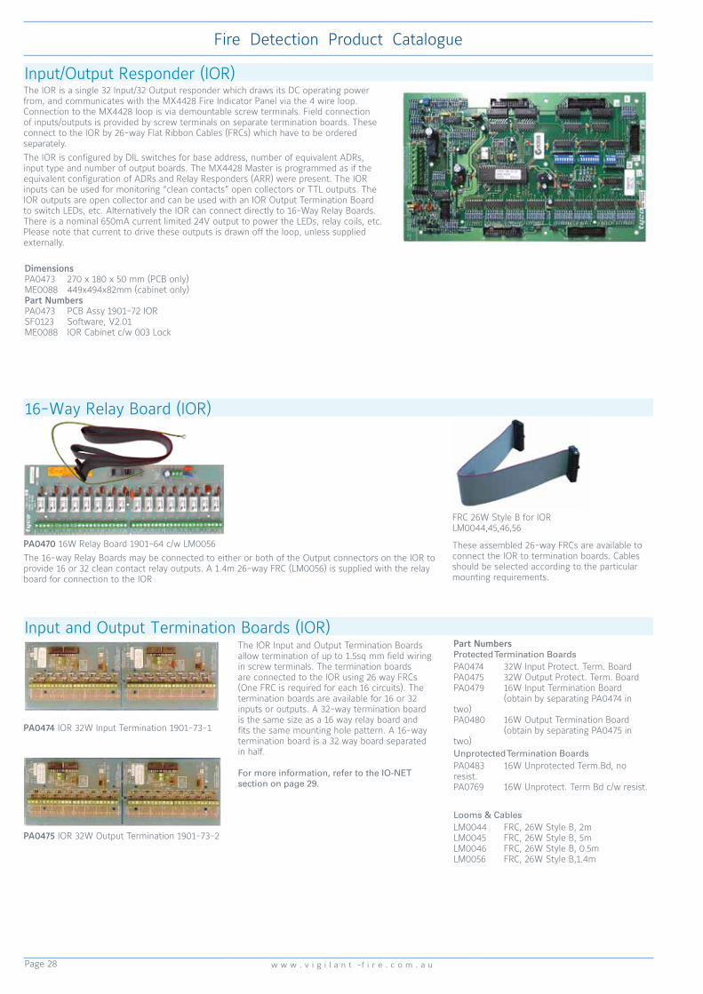
Page 28
Fire Detection Product Catalogue
w w w . v i g i l a n t -f i r e . c o m . a u
The IOR is a single 32 Input/32 Output responder which draws its DC operating power from, and communicates with the MX4428 Fire Indicator Panel via the 4 wire loop. Connection to the MX4428 loop is via demountable screw terminals. Field connection of inputs/outputs is provided by screw terminals on separate termination boards. These connect to the IOR by 26-way Flat Ribbon Cables (FRCs) which have to be ordered separately. The IOR is configured by DIL switches for base address, number of equivalent ADRs, input type and number of output boards. The MX4428 Master is programmed as if the equivalent configuration of ADRs and Relay Responders (ARR) were present. The IOR inputs can be used for monitoring “clean contacts” open collectors or TTL outputs. The IOR outputs are open collector and can be used with an IOR Output Termination Board to switch LEDs, etc. Alternatively the IOR can connect directly to 16-Way Relay Boards. There is a nominal 650mA current limited 24V output to power the LEDs, relay coils, etc. Please note that current to drive these outputs is drawn off the loop, unless supplied externally.
Input/Output Responder (IOR)
PA0470 16W Relay Board 1901-64 c/w LM0056The 16-way Relay Boards may be connected to either or both of the Output connectors on the IOR to provide 16 or 32 clean contact relay outputs. A 1.4m 26-way FRC (LM0056) is supplied with the relay board for connection to the IOR
FRC 26W Style B for IOR LM0044,45,46,56
These assembled 26-way FRCs are available to connect the IOR to termination boards. Cables should be selected according to the particular mounting requirements.
16-Way Relay Board (IOR)
PA0474 IOR 32W Input Termination 1901-73-1
The IOR Input and Output Termination Boards allow termination of up to 1.5sq mm field wiring in screw terminals. The termination boards are connected to the IOR using 26 way FRCs (One FRC is required for each 16 circuits). The termination boards are available for 16 or 32 inputs or outputs. A 32-way termination board is the same size as a 16 way relay board and fits the same mounting hole pattern. A 16-way termination board is a 32 way board separated in half.
For more information, refer to the IO-NET section on page 29.
Input and Output Termination Boards (IOR)
PA0475 IOR 32W Output Termination 1901-73-2
Part NumbersProtected Termination BoardsPA0474 32W Input Protect. Term. BoardPA0475 32W Output Protect. Term. BoardPA0479 16W Input Termination Board (obtain by separating PA0474 in two)PA0480 16W Output Termination Board (obtain by separating PA0475 in two)Unprotected Termination BoardsPA0483 16W Unprotected Term.Bd, no resist.PA0769 16W Unprotect. Term Bd c/w resist.
Looms & CablesLM0044 FRC, 26W Style B, 2mLM0045 FRC, 26W Style B, 5mLM0046 FRC, 26W Style B, 0.5mLM0056 FRC, 26W Style B,1.4m
DimensionsPA0473 270 x 180 x 50 mm (PCB only)ME0088 449x494x82mm (cabinet only)Part NumbersPA0473 PCB Assy 1901-72 IORSF0123 Software, V2.01ME0088 IOR Cabinet c/w 003 Lock

Page 29
Fire Detection Product Catalogue
w w w . s i m p l e x - f i r e . c o m . a u
The MX4428/F4000 Loop Booster overcomes problems such as Responder loop voltage drop and excessive loop length that would otherwise necessitiate a restriction in responders or the use of thicker loop cable. By providing additional power supply capacity to an MX4428/F4000 loop, the Loop Booster is a practical and cost-effective means of overcoming these problems, thus enabling extension of the loop length, additional
Responders, or smaller cable size to be used. In fact, one loop Booster will allow three times the loop current, loop length, or 1/3 the cable resistance. The use of Loop Boosters in an MX4428/F4000 system completely overcomes loop voltage drop as a practical limit to system size and allows a loop to be extended until the 127 Responder limit is reached. The Loop Booster contains its own batteries and charger and when placed in the loop, provides power to a section of the loop and monitors the other. If the voltage on the monitored side falls below 17.0V then the Loop Booster supplies power to this leg as well. It checks at regular intervals to see if the normally monitored leg can self-establish a voltage of greater than 17.0V. The Loop Booster has an ADR and RRM built into it allowing fault and control signals to be conveyed to and from the FIP via the Loop communications. The Loop Booster is able to perform a local battery test and to energise the power supply for the monitored leg of the loop. It can transmit signals to the FIP (e.g. battery test fail, battery low, battery fail and/or charger fault) as well as a monitored leg voltage fail. Remote activation of the battery test and loop relay can be carried out at the FIP by using an ACZ and suitable output logic equations.
MX4428/F4000 Loop BoosterSpecificationsPower 240 VAC +6%, -10% 50Hz, 150WBattery Requirements As per FIPOperating Temperature -5°C to +45°CRelative Humidity 10% to 90% (n/cond)Operating Currents Booster Board 40 mA nominal Indicators 8 mA per LEDOutput Relay Rating 5 A (Emergency Feed)Output Terminals +VNBF 27V nom, 1.6A fuse not battery backed +VBF 27V nom, 1.6A fuse battery backedMaterial 1.6mm mild steelFinish Cream Wrinkle powdercoatDimensions (HWD) 680x470x167mmWeight 16 kg (no batteries)Max. Batt. Size (HWD) 170x165x125mm (for each battery)Part Numbers PA0463 PCB Loop Booster 1901-35FP0487 Loop Booster 1901-36
IO-NET Programmable Control System
The IO-NET programmable controller is a stand-alone or networkable unit that can be used to provide similar functions to a traditional logic controller. It can also be programmed to monitor the F3200/MX4428/MX1 RZDU protocol or provide versatile AS1668 air-handling control and indication functions. Multiple IO-NET units may be connected together (2-wire bus) to provide low cost point-to-point or distributed telemetry for multiple locations. IO-NET can support at least 32 controllers on a 1mm2 line up to 3km long. Modem and fibre optic options allow operation over longer distances or in “noisy” environments. This default mode of operation will only require setting up the DIP switches on the IOR, no factory or on-site programming is required.
Part NumbersPA0498 PCB 1901-117 IO-NET ControllerPA0474 PCB 1901-73-1 IO-NET 32W InputPA0475 PCB 1901-73-2 IO-NET 32W OutputPA0481 PCB 1904-100 RZDU/RS232 I/FPA0483 PCB 1901-103 IOR Unprotected TermPA0470 PCB 1901-64 16W Relay boardPA0700 PCB 1901-120 IO-NET ProgrammerPA0769 PCB 16W Unprotected Term. & resistorsSF0239 IO-NET Controller software V2.01LM0044 FRC 26W Style B, 2mLM0045 FRC 26W Style B, 5mLM0046 FRC 26W Style B, 0.5mLM0056 FRC 26W Style B, 1.4m
IO-NET Controller
PA0498 IO-NET Controller
Each IO-NET Controller has 32 digital inputs and can provide up to 32 programmable outputs. From this starting point the system can be expanded up to a maximum of 128 Controllers on one IO-NET communications network. At least 32 Controllers can be supported on a 1mm2 pair up to 3 km long.
SpecificationsDimensions 270x165x25 mmWeight 310gPower Supply 24Vdc
Part NumbersPA0498 PCB 1901-117 IO-NET ControllerSF0239 IO-NET Controller Software V2.01 (replacement when program memory becomes full)
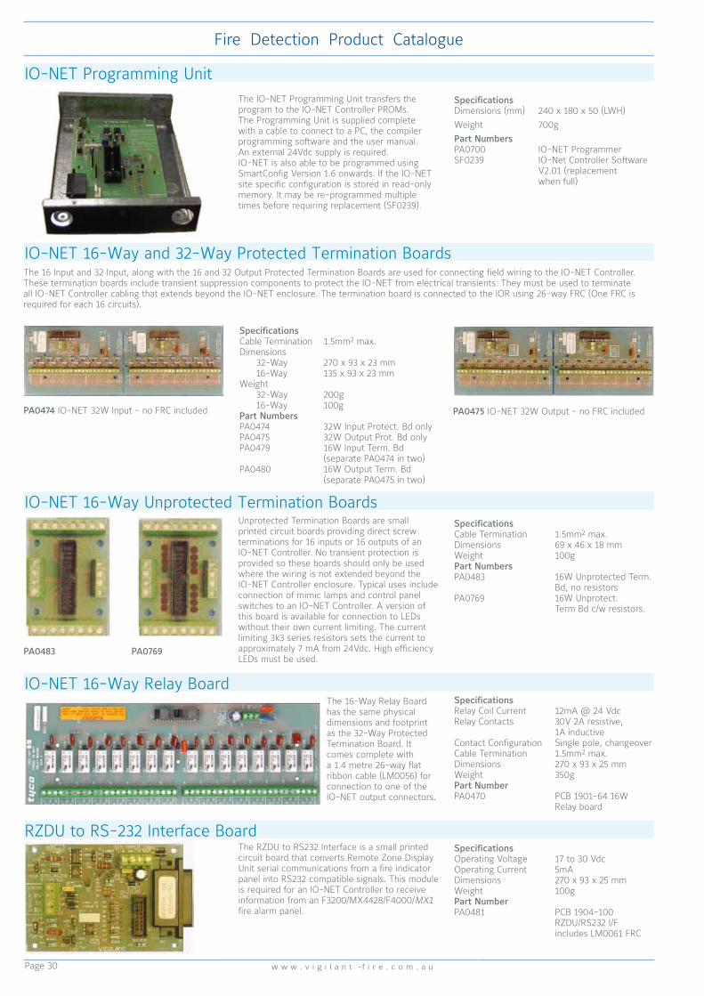
Page 30
Fire Detection Product Catalogue
w w w . v i g i l a n t -f i r e . c o m . a u
IO-NET Programming Unit
IO-NET 16-Way and 32-Way Protected Termination Boards
PA0483 PA0769
Unprotected Termination Boards are small printed circuit boards providing direct screw terminations for 16 inputs or 16 outputs of an IO-NET Controller. No transient protection is provided so these boards should only be used where the wiring is not extended beyond the IO-NET Controller enclosure. Typical uses include connection of mimic lamps and control panel switches to an IO-NET Controller. A version of this board is available for connection to LEDs without their own current limiting. The current limiting 3k3 series resistors sets the current to approximately 7 mA from 24Vdc. High efficiency LEDs must be used.
IO-NET 16-Way Unprotected Termination BoardsSpecifications Cable Termination 1.5mm2 max.Dimensions 69 x 46 x 18 mmWeight 100gPart NumbersPA0483 16W Unprotected Term. Bd, no resistorsPA0769 16W Unprotect. Term Bd c/w resistors.
The 16-Way Relay Board has the same physical dimensions and footprint as the 32-Way Protected Termination Board. It comes complete with a 1.4 metre 26-way flat ribbon cable (LM0056) for connection to one of the IO-NET output connectors.
IO-NET 16-Way Relay BoardSpecifications Relay Coil Current 12mA @ 24 VdcRelay Contacts 30V 2A resistive, 1A inductiveContact Configuration Single pole, changeoverCable Termination 1.5mm2 max.Dimensions 270 x 93 x 25 mmWeight 350gPart Number PA0470 PCB 1901-64 16W Relay board
RZDU to RS-232 Interface BoardThe RZDU to RS232 Interface is a small printedcircuit board that converts Remote Zone DisplayUnit serial communications from a fire indicatorpanel into RS232 compatible signals. This moduleis required for an IO-NET Controller to receiveinformation from an F3200/MX4428/F4000/MX1 fire alarm panel.
Specifications Operating Voltage 17 to 30 VdcOperating Current 5mADimensions 270 x 93 x 25 mmWeight 100gPart Number PA0481 PCB 1904-100 RZDU/RS232 I/F includes LM0061 FRC
The IO-NET Programming Unit transfers the program to the IO-NET Controller PROMs. The Programming Unit is supplied complete with a cable to connect to a PC, the compiler programming software and the user manual. An external 24Vdc supply is required. IO-NET is also able to be programmed using SmartConfig Version 1.6 onwards. If the IO-NET site specific configuration is stored in read-only memory. It may be re-programmed multiple times before requiring replacement (SF0239).
Specifications Dimensions (mm) 240 x 180 x 50 (LWH)Weight 700gPart NumbersPA0700 IO-NET ProgrammerSF0239 IO-Net Controller Software V2.01 (replacement when full)
PA0475 IO-NET 32W Output - no FRC included
The 16 Input and 32 Input, along with the 16 and 32 Output Protected Termination Boards are used for connecting field wiring to the IO-NET Controller. These termination boards include transient suppression components to protect the IO-NET from electrical transients. They must be used to terminate all IO-NET Controller cabling that extends beyond the IO-NET enclosure. The termination board is connected to the IOR using 26-way FRC (One FRC is required for each 16 circuits).
PA0474 IO-NET 32W Input - no FRC included
Specifications Cable Termination 1.5mm2 max.Dimensions 32-Way 270 x 93 x 23 mm 16-Way 135 x 93 x 23 mmWeight 32-Way 200g 16-Way 100gPart NumbersPA0474 32W Input Protect. Bd onlyPA0475 32W Output Prot. Bd onlyPA0479 16W Input Term. Bd (separate PA0474 in two)PA0480 16W Output Term. Bd (separate PA0475 in two)

Page 31
Fire Detection Product Catalogue
w w w . s i m p l e x - f i r e . c o m . a u
PA0711 RS485 Comms PCB 1901-139-1 Plug-on (Modem connection to MX4428 Main Board - external power). The PA0711 can be used to interface an MX4428 FIP with the RS485 network. The board is mounted on the modem connector, located at the top of the MX4428 Main Board.
PA0712 RS232 to RS485 PCB 1901-139-2 (RS232 to RS485 - external power). It is used to convert between RS485 and RS232 level signals. Because RS485 links can be much longer than RS232, the PA0712 can be used to transmit serial data over long cables between devices which have RS232 serial ports (e.g., between the F4000 printer port and the printer). It can also be used to interface a PC with the RS485 network. Loom LM0065, a 500mm long cable with both RS232 DB9 socket and plug fitted must be ordered separately.
PA0773 RS485 Comms CMOS PCB 1901-139-3 FRC only (FRC connection - including power). The PA0773 is used to interface an F3200 FIP, MX4428 FIP, PTM, NLDU, MODBUS BRIDGE, RDU or NDU with the RS485 network. This RS485 Communication Board is mounted on four metal stand-offs, which are used for earthing the PCB. This RS485 board connects to the controller board via a 10 way FRC LM0172 (ordered separately), which is also used to power the RS485 Board.
RS485 Network InterfaceSpecifications PA0711 PA0712 PA0773Operating Voltage Ext.24V 8.5 to 30Vdc - J2 5V 4.8 to 5.2VdcQuiescent Current RX only 24V 24mA 26mA - RX only 5V 2mA 26mA 26mA TX act. 24V 50mA 75mA - TX act. 5V 25mA 75mA 75mARel. Humidity 10% to 95% (n/cond)Ambient Temp. -5°C to +75°CFPANZ Listed VF/636Dims (mm) 130x50 156x50 156x50Part NumbersPA0711 RS485 PCB Plug-on (ext pwr)PA0712 RS232 to RS485 (ext pwr)PA0773 RS485 CMOS FRC only
PA0868 CMOS/TTL RS232 I/F PCB
I-HUB Intelligent Network Hub
I-HUB Ordering CodesFP0770 1931-102, NDU to Ring NET upgrade kit. Includes PA0839 mounted on deeper backplate, LM0152, LM0065, mounting hardware.FP0771 MX4428/F3200, Ring NET upgrade kit Includes PA0839 on bracket, LM0151, LM0152, LM0065. Note an F3200 may require an IC0358 to be fitted to U13.PA0839 PCB assy, ECM9603 PANEL-LINK I-HUB Includes I-HUB PCB, software, LM0065KT0144 PMB/TPI RS485 support module kit Includes PA0712, LM0084, mounting hardware.PA0773 PCB 1901-139-3, RS485 bd, TTLPA0868 PCB 1931-110, CMOS RS232 interfacePA0878 PCB 1931-118, CMOS/TTL signal splitter
LM0572 Loom1901-303, I-HUB to OSD139 Includes a zener diode, dropping resistor for PSU.LM0065 10-way FRC connector to DB9M & DB9F (ribbon cable - suppllied with I-HUB)LM0076 DB9F to DB9F ‘null modem’ cableLM0084 10 way FRC to 10 way FRC 0.35mLM0091 10 way FRC to 10 way FRC 0.5mLM0151 10-way FRC to Molex crossover cable, (Port 5 to MX4428 molex ‘Modem’ connector)LM0152 10-way FRC to 10-way FRC special crossover cable (Port 5 to MX4428/F3200 10-way network connector)LM0160 10 way FRC to 10 way FRC 1mLT0229 I-HUB User’s ManualSF0202 Software, PanelLink I-HUB V1.14 EPROM
FP0771 Ring NET Upgrade Kit
The I-HUB performs bridging and routing functions for devices on the VIGILANT Panel-Link network, supporting ring, multi-drop and point to point networks. It can assist in reducing congestion on large networks by using its filtering and ‘routing’ capabilities. The I-HUB has five network ports; which allow the I-HUB to be connected to a network of devices or to a single device. Messages received on one port can be routed to any or all of the other ports. Ports 1 & 2 are 2 or 4 wire RS485 or fibre, Ports 3 & 4 are RS232. Port 5 is a TTL level serial port.
SpecificationsOperating Voltage 9.6 to 28VdcOperating Current 140mA (9.6V) to 85mA (28V)Ambient Temp -5°C to +45°CRelative Humidity 0 to 95% (non/cond)Dimensions (mm) 265 x 95 x 25 (LWH)Weight 0.25kgActivFire Listed afp-2320FPANZ Listed VF/634
OSD139 Fibre Optic ModemSpecificationsOptical Wavelength 850nm nominal (HS) 1310nm niominal (HSL)Optical Connector STAmbient Temp -20°C to +75°CRelative Humidity 0 to 95% (non/cond)Dimensions (mm) 15 x 44 x 80 (HWD)Weight 200gPart NumbersOSD139HS HS Multimode F/O modemOSD139HSL HS Single mode F/O modemFP1032 OSD139 F/O modem x2 mounting kit
The OSD139HS Asynchronous RS232 Transceivers can interconnect one RS232 data channel over 3km of multimode fibre (OSD139HS) or over 40km of single mode fibre (OSD139HSL). These can provide complete end-to-end isolation of a full duplex asynchronous data transmission at up to 120kbps.The OSD139HS are high performance fibre optic modems capable of linking asynchronous RS232 data over several kilometres at speeds ranging from DC to 120kbps. Recommended for I-HUB Ring network applications.

Page 32
Fire Detection Product Catalogue
w w w . v i g i l a n t -f i r e . c o m . a u
Panel-Link MODBUS Bridge (PMB)SpecificationsOperating Voltage 9.6 to 28VdcOperating Current 135mA (9.6V) to 85mA (28V)Ambient Temp -5°C to +45°CRelative Humidity 0 to 95% (non/cond)Dimensions (mm) 265 x 95 x 25 (LWH) (PCB) 450W x 280D x 80H (box)Weight 0.25kg (PCB) 4kg (box)Battery Capacity 6.5Ah (box)Part NumbersFP0699 PMB c/w PSU in boxPA0639 PMB PCB incl. mounting hardware & FA2083SF0165 S/ware PMB V1.24 EPROMKT0144 Kit PMB RS485 ModulePA0790 PCB ECM9603 I/O BoardLT0202 PMB User Manual
The Panel-Link Modbus Bridge (PMB) is designed to translate data from VIGILANT fire alarm systems on a Panel-Link network to a Modbus communication line. The PMB not only monitors the Panel-Link network, but also provides a means of direct control over the fire systems. The PMB database contains data on the states
and conditions of fire panels, as well as zone and point information. A Modbus master can access this data by polling the relevant addresses of the PMB and can write to holding registers sending network variables and issuing commands to panels on the Panel-link network. The PMB also has 16 I/O ports which can be read and
written to by the Modbus Master. Two of these pins can be programmed as a sounder output if a fault develops in the Modbus system, and an isolate input which can locally isolate the PMB sounder driver.
MODBUS Bridge (MBB)SpecificationsOperating Voltage 19 to 28.5VdcOperating Current 25mA (RS232) 50mA (RS485)Ambient Temp -5°C to +45°CRelative Humidity 0 to 95% (non/cond)Dimensions (mm) 380 x 100 x 42(LWH) (PCB) 450 x 280 x 80 (LWH) (box)Weight 4kg (box) 425g (PCB only)Part NumbersFP0706 MODBUS Bridge, RS485SF0144 s/w, MODBUS Bridge, V1.02SF0220 s/w, MODBUS Bridge, IO-NET I/F V2.01LT0179 MBB User Manual
The Modbus Bridge (MBB) is designed to translate data from MX4428/F3200 fire alarm panel RZDU output to a Modbus communication line. It does so by monitoring the MX4428/F3200 panel, as appropriate, and storing the information it receives in its database. The bridge is also able to send data received from the MODBUS master onto an IO-NET network, to enable the MODBUS master to control outputs on IO-NET controllers. It is available packaged in a cabinet or as a board set for incorporation into other equipment. MODBUS communications options are RS232 or RS485.
Panel-Link Internet Protocol Bridge (PIB)
The PIB is a device for interfacing a single VIGILANT Panel-Link device on to a 10BaseT Ethernet network to allow networking with other PIBs and Panel-Link devices. IP Networking is utilised for the Internet, PC Networks and Industrial Networks. IP connection equipment for almost any type of media is readily available.The PIB is especially applicable to large and/or wide-spread sites. It is also useful where it is not possible or economic to install physical cabling. The PIB can be used to connect to an Ethernet network (dedicated, or shared) or a variety of other physical media (e.g. fibre optic) via third party switches or media convertors. A redundant ring of single-mode or multi-mode fibre can easily be configured using the switches listed.One PIB is normally used at each panel; however to connect multiple panels, an I-HUB must be used between the PIB and the panels.The PIB is self-configuring for many situations. It also has filtering and routing capabilities for larger network optimisation.
Configuration and diagnostics are performed from a standard PC web browser anywhere on the network. The PIB also provides remote across-network access to the diagnostic port of any panel directly connected to a PIB. It is supplied complete with Ethernet, MX4428 serial port, and I-HUB/panel FRC network port looms.
For more information on IP Networking, refer to Page 35.
SpecificationsOperating Voltage 15-28Vdc1 or 10-14Vdc2
Operating Current 60mA (excluding LEDs)Dimensions (mm) 192 x 120 x 30 (LWH)ActivFire Listed afp-2320FPANZ Listed afp-2320Part NumbersFP0986 Panel-Link Internet Protocol Bridge (PIB)SU0319 MOXA 5 Port Ethernet Switch (2 Multi Mode Fibre)SU0320 MOXA 5 Port Ethernet Switch (2 Single Mode Fibre)SU0325 MOXA 5 Port Ethernet Switch EDS-405ASU0326 MOXA 8 Port Ethernet Switch EDS-408ALT0519 PIB User ManualLT0536 IP Networking for Fire Application & Design Manual
1. Connected between 16VAC & 12Vdc terminals2. Connected between Batt+ & — terminals

Page 33
Fire Detection Product Catalogue
w w w . s i m p l e x - f i r e . c o m . a u
Network LED Display Unit (NLDU)SpecificationsOperating Voltage 24VdcOperating Current 150mA (excluding LEDs)Part NumbersFP0695 NLDU Board Set, 1942-6 Includes PA0804, PA0703, PA0773, mounting hardwareFP0696 NLDU, Packaged, 1942-5 Incl. slimline surf mnt cab, PA0804, PA0703, PA0773, mounting hardwarePA0804 PCB 1931-84-1, Ctrlr Net/NDU,no S/WPA0703 PCB 1931-27,F3200 Remote I/F PA0773 PCB 1901-139-3, RS485,CMOS,FRCSF0145 NLDU Software V2.03LT0188 NLDU User Manual
The VIGILANT Network LED Display Unit connects to a Panel-Link network to perform a variety of functions. A single NLDU may simultaneously perform any or all of: event printing, LED display, RZDU output, and bridge functions. Typical NLDU applications are:
• Site-wide network mimic panel (up to 528 LED sets).• Repeat LED indications at a remote network panel.• Event printing of selected event types from selected network panels.• IO-NET Interface for networked panels.
The Protocol Translation Module (PTM) provides an interface between VIGILANT fire panels on a Panel-Link network and a network event printer or an XL Graphics computer system. The PTM is programmable as to which panels/events are printed or sent to the XL Graphics system.
Protocol Translation Module (PTM)
SpecificationsOperating Voltage 24VdcOperating Current 19mA (excluding LEDs)Dimensions (mm) 450W x 280D x 80H (box)FPANZ Listed VF/616Part NumbersFP0586 Protocol Translation Module (PTM in box)PA0799 Protocol Translation Module PCB only
• Interfaces VIGILANT fire panels or Panel-Link network to network event printer or XL Graphics
• Event printer could be actual printer or event receiving system - Nurse Call, BMS, etc., that can handle text strings
• Configurable for what event types to print: Zone, System, Circuit, Point, Relay, System Operating
• Programmable group membership• Individual fire panels can be selected for logging
events/passing to XL Graphics
• Selectable fire panel monitoring - failure events generated if no messages received from each panel
• Programmable Panel-Link network operation - including ACK broadcasts
• Non-volatile storage of programmed parameters
• Supplied in painted metal cabinet• 12V or 24Vdc operation• RS232 interface to printer/XL Graphics

Page 34
Fire Detection Product Catalogue
w w w . v i g i l a n t -f i r e . c o m . a u
The I-HUB is a part of the family of products that connect to the VIGILANT Panel-Link network. The I-HUB performs bridging and routing functions for the Panel-Link network. The I-HUB supports ring, multi-drop and point-to-point networks. Deploying an I-HUB in a ring can add extra levels of redundancy and service protection otherwise not possible in conventional Panel-Link networks.The I-HUB can be used in a number of different applications. The following diagrams illustrate some of the possible I-HUB uses. Please note that these
are a small overview of what can be achieved using the I-HUB and do not represent detailed implementations. Duplicated channel operation is a standard feature of the Panel-Link Network and in certain conditions is a requirement to meet fire installation standards. Refer to the appropriate standard, AS1670.1 for Australia, NZS4512 for New Zealand.
The I-HUB can be used to connect two to four Panel-link networks together to allow a greater physical length as shown in Figure 2.
The I-HUB can be used to interconnect two or more networks that use different media or signalling speeds.
Two I-HUBs can be used to connect two distant Panel-Link networks together using fibre optic cables, modems or a customer supplied network (WAN).
With large systems, care must be taken to minimise the number of messages that are passed through an I-HUB so as to avoid overloading any part of the network. For slow data links such as one using 1200 baud modems, the absolute minimum number of messages should be passed across it. With the exception of RING mode, network designs that result in more than one path to any one device must be avoided.
Fig 1 Network Ring example
Fig 2 Joining Multiple Networks
Fig 3 Networking Different Media Fig 4 Joining Two Networks Together
The “RING” method shown in Figure 1 provides a level of redundancy not found in other kinds of network topology. The ‘ring’ configuration, with an I-HUB incorporated in each panel, is one way of providing the two separate paths required by AS1670.1 section 2.6.1 (c) and NZS4512:2003 402.2 (o).
I-HUB Ring Networking
Part NumbersFP0770 NDU to Ring Network Upgrade KitFP0771 F3200/MX4428 Ring Network Upgrade KitPA0839 PCB ECM9603 Panel-Link I-HUBKT0144 Kit PMB/TPI RS485 Support ModulePA0773 PCB RS485 TTLPA0868 PCB CMOS RS232 InterfacePA0878 PCB CMOS/TTL Signal SplitterPA0880 PCB DB25 to 10-way FRC AdaptorLM0572 LOOM, I-HUB to OSD139 Fibre Optic ModemLM0076 ECM Programming Cable, DB9F - DB9F Null ModemOSD139HS HS Multimode Fibre Optic ModemOSD139HSL HS Single mode Fibre Optic ModemFP1032 OSD139 Fibre Optic Modem x2 Mounting Kit
I-HUB
I-HUB
I-HUB
I-HUB
I-HUB
I-HUBI-HUB
PANEL-LINK NETWORK 1 PANEL-LINK NETWORK 2
PANEL-LINK NETWORK 3
GRAPHICS
TTL SERIAL
RS232
RS485
GRAPHICS
I-HUB
PANEL-LINK
PANEL-LINK
PANEL-LINK
PANEL-LINK
I-HUB
I-HUBFIBRE OPTIC CABLE, RS485 OR MODEMS

Page 35
Fire Detection Product Catalogue
w w w . s i m p l e x - f i r e . c o m . a u
VIGILANT IP Networking
I-HUB
PIB
PIB
PIB
PIBPIB
ETHERNET SWITCH
ETHERNET SWITCH
ETHERNET SWITCH
ETHERNET SWITCH
ETHERNET SWITCH
ETHERNET SWITCH
QE90 EWIS
XLG-C/S
MX4428 FIP connected to Fire Brigade
MX4428 FIP with F3200 via Copper Panel-Link Network
Features Benefits
Uses an industry-standard interface (Ethernet) and standard protocols Suports a wide variety of third party interfaces
Can use a wide variety of physical media Provides a cost-effective solution for short and long distance communication, i.e.,Can use fibre-optics to eliminate susceptibility to EMC (electrical interference)Can use wireless transmission systems where physical access is difficult
Provides remote access to panel diagnostics and programming, as well as providing networking
Diagnostics and programming of a whole network can be done from a single point on site, or potentially from off site
Web access is provided via panel serial port Uses standard web browser for remote diagnostics. No special software (such as a terminal emulator) needs to be installed. This is particularly useful when using a customer’s network
Many ‘channels’ can be multiplexed over the same cable The same network can be used for a Fire and EWIS network, Colour Graphics client / server network, etc.
IP networking can be used for subsections of a Panel-Link network Existing installations can be upgraded to IP networking in stages, or can use mixed systems
The interface is specially designed for Panel-Link and VIGILANT products Avoids a large number of compromises that result if an IP interface was used
VIGILANT IP (Internet Protocol) Networking opens up a world of previously unimaginable possibilities, particularly for large, remote, and difficult sites. It is now both possible and easy for fire systems to be networked across large distances (such as within, or even between, cities) and / or to network on a large site using a customer’s own network without installing new dedicated cables.
IP networking is often the most cost-effective method of networking between panels, and/or providing remote diagnostics and programming for many panels from a single point on the site, or even from off-site. This applies particularly when long distances are involved, or where special media must be used (i.e., media other than copper wire).
IP networking can use an existing customer’s network (where standards compliance is not required for the networking), or alternatively a dedicated potentially standards-compliant IP network can be installed for the fire system. Note: – as yet the IP networking equipment described in this guide is not listed.
If a connection to the internet can be provided, remote diagnostic access could be obtained from virtually anywhere in the world.
The VIGILANT IP solution uses a PIB (Panel-Link IP Bridge) to connect between a VIGILANT Panel-Link device and the IP network. Additional Ethernet switches and Ethernet Extenders allow operation over fibre optic cable or long cable distances.
F3200 FIP
IP Network
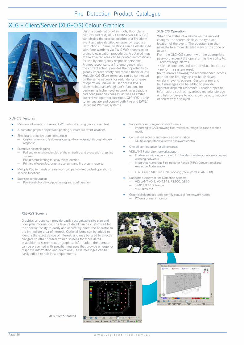
Page 36
Fire Detection Product Catalogue
w w w . v i g i l a n t -f i r e . c o m . a u
XLG - Client/Server (XLG-C/S) Colour GraphicsUsing a combination of symbols, floor plans, pictures and text, XLG-Client/Server (XLG-C/S) can display the precise location of a fire alarm event and give detailed emergency response instructions. Communications can be established with floor wardens via EWIS WIP phones to co-ordinate evacuation procedures. A detailed map of the affected area can be printed automatically for use by emergency response personnel. Prompt response to a fire emergency, with the correct action, provides the opportunity to greatly improve safety and reduce financial loss.Multiple XLG Client terminals can be connected on the same network for redundancy or ease of operation. Individual user access levels allow maintenance/engineer’s functions for performing higher level network investigations and configuration changes, as well as limited lower-level operator functions. XLG-C/S is able to annunciate and control both Fire and EWIS/Occupant Warning systems.
XLG-C/S OperationWhen the status of a device on the network changes, the screen displays the type and location of the event. The operator can then navigate to a more detailed view of the zone or device. From the XLG-C/S screen (with the appropriate password access) the operator has the ability to: • acknowledge alarms • silence sounders and turn off visual indicators • perform a system reset. Route arrows showing the recommended access path for the fire brigade can be displayed on alarm events screens. Custom alarm and fault messages can be added to provide operator dispatch assistance. Location-specific information, such as hazardous material storage and lists of people to notify, can be automatically or selectively displayed.
XLG-C/S Features
• Monitors all events on Fire and EWIS networks using graphics and text
• Automated graphic display and printing of latest fire event locations
• Simple and effective graphic interface— Custom alarm and fault messages guide an operator through dispatch
response
• Extensive history logging— Full and extensive event log of the entire fire and evacuation graphics
system— Rapid event filtering for easy event location— Printing of event log, graphics screens and fire system reports
• Multiple XLG terminals on a network can perform redundant operation or specific functions
• Easy site configuration— Point-and-click device positioning and configuration
• Supports common graphics file formats— Importing of CAD drawing files, metafiles, image files and scanned
media
• Centralised security and service administration— Multiple operator levels with password control
• One-off configuration for all terminals
• VIGILANT Panel-Link network support— Enables monitoring and control of fire alarm and evacuation/occupant
warning networks— Integrates numerous Fire Indicator Panels (FIPs); Conventional and
Analogue Addressable
— F3200 and MX1 via IP Networking (requires VIGILANT PIB)
• Supports a variety of Fire Detection systems— VIGILANT MX1, MX4248, F3200, QE90
— SIMPLEX 4100 range — MINERVA MX
• Graphical diagnostic tools identify status of fire network nodes— PC environment monitor
XLG-C/S Screens
Graphics screens can provide easily recognisable site plan and floor plan information. The level of detail can be customised for the specific facility to easily and accurately direct the operator to the immediate area of interest. Optional icons can be added to identify the exact device of interest, and may be used to directly navigate to other predetermined screens for more detail. In addition to screen text or graphical information, the operator can be presented with specific messages that provide emergency response information and directions. These messages can be easily edited to suit local requirements.
XLG Client Screens

Page 37
Fire Detection Product Catalogue
w w w . s i m p l e x - f i r e . c o m . a u
XLG-C/S Operation XLG-C/S Virtual ECP Screen
Campus TCP/IP LAN or WAN
Fire & Security Centre
Remote Access Off-Campus
Squash Courts
Arts Building
Administration Building
Engineering & Maintenance
Graphics Client
Global Graphics Server
Remote Graphics Client
Collective Panel
Collective & Addressable Panels
s
EWIS Panel
PSTN
Panel-Link
I-HUB
Network
SECP/VDU Interface
I-HUB
PC Printer
Addressable Panels
Network Printer
Part NumbersCG0002-CS XLG-C/S Client/Server
Software & DongleCG0002-CLIENT XLG-C/S Client only
SoftwareFP0586 PTM Protocol
Translation Module in box
FP0697 SCP/VDU Interface
Hardware Requirements:
1. Fire panels on the Panel-Link network connect to the XLG Server using the PTM, I-HUB or PIB interface. EWIS panels are connected using the SECP/VDU Interface. The XLG Server requires a serial comm’s port for each interface.
2. The XLG Server must have a free USB port.
Software Requirements:
1. WINDOWS7 32-bit or 64-bit Operating System
Multiple Network Integration
XLG-C/S supports extensive fire network integration and interconnection. Multiple networks as well as conventional FIPs can be monitored and controlled by XLG-C/S.Each fire network and/or standalone FIP connected to the Panel-Link network interfaces to the XLG Server using a suitable communications device such as the Protocol Translation Module (PTM), Intelligent-Hub (I-HUB) or Panel-Link IP Bridge (PIB) depending on the network configuration. EWIS networks interface to the XLG Server using a SECP/VDU Interface.Each XLG Client terminal communicates with the XLG Server using IP networking.
XLG-C/S Operation on Panel-Link Network
• VIGILANT Panel-Link Network - Multidropped RS485 connections or IP via various media - Up to 64 networked devices multidropped depending on required
functionality - Multidropped cable length <1200m, shielded
twisted pair - Galvanic isolation between panels & network
• High noise immunity • Reduced earth loop problems - I-HUBs used to extend copper network (ring configuration) - Link Integrity function supervises XLG-C/S network
See also pages 34 (I-HUB Networking) and 35 IP Networking).

Page 38
Fire Detection Product Catalogue
w w w . v i g i l a n t -f i r e . c o m . a u
Analogue Addressable 130 Series Detectors
The C131A-Mk2 dual-chamber ionisation smoke detector contains a state-of-the-art sensing chamber and analogue communication electronics. Used in conjunction with the VIGILANT MX4428 panel, the C131A-Mk2 has a high degree of false alarm immunity thanks to the advanced SmartSense algorithms.The detector mounts on the B501AUS or B200SR base and is designed to provide open area protection. Two LEDs on each detector illuminate during alarm to provide 360° alarm indication. An optional remote LED can also be fitted.
C131A-Mk2 Ion Smoke DetectorSpecificationsOperating Voltage 15 to 32VdcQuiescent Current (max.) 300µAAlarm Current (max.) 6.5mAExternal Output Drive (max.) 5mARelative Humidity 10% to 93% (n/cond)Ambient Temperature -10°C to +49°CDimensions 102 dia. x 51H mmWeight 160gRemote Indicator E500 Mk2 SeriesActivFire Listed afp-2486FPANZ Listed VF/301Part Number C131A-Mk2
The P131A-Mk2 photoelectric smoke detector contains a state-of-the-art sensing chamber and analogue communication electronics. Used in conjunction with the VIGILANT MX4428 panel, the P131A-Mk2 has a high degree of false alarm immunity thanks to the advanced SmartSense algorithms.
The detector mounts on the B501AUS or B200SR base and is designed to provide open area protection. Two LEDs on each detector illuminate during alarm to provide 360° alarm indication. An optional remote LED can also be fitted.
P131A-Mk2 Photoelectric Smoke DetectorSpecificationsOperating Voltage 15 to 32VdcQuiescent Current (max.) 360µAAlarm Current (max.) 6.5mAExternal Output Drive (max.) 5mARelative Humidity 10% to 93% (n/cond)Ambient Temperature -10°C to +49°CDimensions 102 dia. x 51H mmWeight 170gRemote Indicator E500 Mk2 SeriesActivFire Listed afp-2487FPANZ Listed VF/302Part Number P131A-Mk2
The T131A-Mk2 heat detector is a state-of-the-art dual thermistor heat detector with analogue communication electronics. Used in conjunction with the VIGILANT MX4428 panel, the T131A-Mk2 has a high degree of false alarm immunity thanks to the advanced SmartSense algorithms. It is panel programmable to either Type A (with Rate Of Rise) orType B (fixed temperature only) to maximise system design flexibility.The detector mounts on the B501AUS or B200SR base and is designed to provide open area protection. Two LEDs on each detector illuminate during alarm to provide 360° alarm indication. An optional remote LED can also be fitted.
T131A-Mk2 Heat DetectorSpecificationsOperating Voltage 15 to 32VdcQuiescent Current (max.) 300µAAlarm Current (max.) 6.5mAExternal Output Drive (max.) 5mARelative Humidity 10% to 93% (n/cond)Ambient Temperature -20°C to +45°CDimensions 102 dia. x 51H mmWeight 140gRemote Indicator E500 Mk2 SeriesActivFire Listed afp-2488FPANZ Listed VF/205Part Number T131A-Mk2
The 130 series are a range of low-profile Analogue Addressable fire detectors. These unobtrusively-styled detectors have a number of unique design features to improve their operation, installation and ease of servicing. Using the VIGILANT MX4428 CIE, up to 99 detectors and 99 modules can be supported per MPR, on an analogue addressable loop length up to 2000 metres. The advanced SmartSense Algorithm used by the MX4428 significantly reduces response to non-fire phenomena. The detector address is set by rotary decade switches on the back of the detector. Two indicating LEDs can be programmed via the FIP to blink as the detector is polled and show constant red when in alarm.

Page 39
Fire Detection Product Catalogue
w w w . s i m p l e x - f i r e . c o m . a u
The D51Z131 Duct Sampling Unit consists of a D51B duct housing fitted with a B501AUS base in readiness for fitting an analogue addressable P131 photoelectric smoke detector. The D51B is designed to sample air in air conditioning ducts and pass the air through the smoke detector. The housing is fixed on the outside of the duct to be sampled, allowing easy access for detector servicing and replacement of the dust filter. To cater for most duct sizes, a sampling tube extension is available in 3 metre lengths. VIGILANT E500 Mk2 Series Remote Indicators can be used for remote indication of an alarm.
D51Z131 Duct Sampling Unit
B200SR Sounder Base
The B200SR is a direct replacement for the Z132A Sounder Base and provides mounting facilities and an inbuilt audible alarm for the 130 Series detectors. The sounder actuates whenever its associated detector enters an alarm state, providing a 90dB signal at a distance of 3 metres. To ensure that the sounder operation does not interfere with normal detector operation, the B200SR requires a separate 24Vdc supply that is electrically and physically separated from the detector supply. For supervision of the 24V line, an ADM131 Monitor Module and 24V relay may be used. For activation of a group of sounders from any one group of detectors, an ADC130 Control Module and 24V relay is used.
SpecificationsSounder Supply Voltage 17 to 32VdcSounder On Current 35mASounder Off Current 1mALoop Current (quiescent) 0µALoop Current (alarm) 700µAQuiescent Current (max.) 250µASounder Output >85dBA at 3mRelative Humidity 10% to 93% (n/cond)
Ambient Temperature 0°C to +49°CDimensions (Dia x H) 175 x 51 mmWeight 227gActivFire Listed with 130 series detectorsFPANZ Listed VF/413Part Number B200SR
SpecificationsDuct Pressure* -1.15 to +3.0 kPa Sampling Tube Length 160mm minimum Max. Duct Width 1.8mDimensions Base & Cover (LWH) 278x190x113 mm Sampling Tube Pitch 122mm Duct Holes Required 24mm dia. x 2 placesRemote Indicator E500 Mk2 Series Not ActivFire ListedPart NumbersD51Z131 B501AUS Base fittedD51COVER D51 Cover only c/w screwsD51L Baffle box of 10D51F Filter box of 10 D51T3 3m Sampling TubeD51K100 Sampling Tube End Cap (packet of 10)
*AS 1603.13-1998 test
130 Series Detector BasesSpecificationsSounder Supply Voltage 17 to 32VdcRelative Humidity 10% to 95% (n/cond)
Ambient Temperature -5°C to +45°CWeight 187gActivFire Listed with 130 series detectorsFPANZ Listed with 130 series detectorsPart NumbersB501AUS Analogue Detector Base
The B501AUS is a direct replacement for the Z131A Detector Base, and should be mounted on a flat surface with suitable fasteners. A tamper-resist feature is incorporated in the base which, when used, prevents removal of the detector without using a small screwdriver or similar tool.

Page 40
Fire Detection Product Catalogue
w w w . v i g i l a n t -f i r e . c o m . a u
The ADCS130-Mk2 Supervised Relay Control Module provides a single switched supervised output on the MPR addressable loop. It supervises the output wiring for open or short circuit faults when the output is de-energised. The ADCS130-Mk2 can directly replace an ADC130 configured for supervised output operation (tabs in place). The ADCU130-Mk2 Unsupervised Relay Control Module provides two change-over relay outputs on the MPR addressable loop that operate together under control of the MX4428. The two relay outputs are electrically isolated and there is no supervision of the output wiring. The ADCU130-Mk2 can directly replace an ADC130 that has been used in unsupervised output mode (tabs broken).Either module mounts to a double gang back box with a minimum depth of 50mm.
ADCx130-Mk2 Output Control ModuleSpecificationsOperating Voltage 15 to 32VdcQuiescent Current (max.) 350µASupply Current (max.) 6mARelay Contact Rating (max.) Resistive 2A 30Vdc Inductive 1A 30Vdc 100V Audio Line 30 wattsSupervised Line Length 100mCable Size 1 to 4 mm2
Relative Humidity 10% to 95% (n/cond)Ambient Temperature 0°C to +49°CDimensions 120x108x34mmWeight 140gActivFire Listed afp-1446FPANZ Listed SS/604Part Numbers ADCS130-Mk2 (Supervsed)
ADCU130-Mk2(Unsuprvsd)
The ADM130-Mk2 is an addressable input module that allows the connection of hard contact detection devices. The module’s two wire input is supervised for faults. An LED indicator allows visual monitoring of the module’s status. An output is provided for connection to a remote LED indicator. Suitable remote indicators allow visual indication of the module’s alarm status
ADM130-Mk2 Monitor ModuleSpecificationsOperating Voltage 15 to 32VdcQuiescent Current (max.) 350µAAlarm Current (max.) 5mASupervised Line Length 100m max.Input Voltage (max.) 11VRelative Humidity 10% to 93% (n/cond)Ambient Temperature 0°C to +49°CDimensions 120x108x34mmWeight 130gActivFire Listed afp-1446FPANZ Listed SS/601Part Number ADM130-Mk2
The ADS130-Mk2 Short Circuit Isolator protects MPR analogue addressable loops against short circuits. When a loop short circuit occurs between ADS130-Mk2 isolators, they disconnect the section of the cable containing the short, allowing the rest of the loop to continue to function. ADS130-Mk2 isolators are usually placed between zones so that a short circuit will affect only one zone and any loss of detection capability will be minimised. The ADS130-Mk2 isolators automatically connect the loop at power-up and after removal of a short circuit. An inbuilt yellow LED provides a visual indication of isolator status.
SpecificationsOperating Voltage 15 to 32VdcQuiescent Current (max.) 450µA @ 24VdcSupply Current (shorted o/p) 17mAADS130s per MPR 15 max.Max. no. Devices betw’n ADS 25Humidity 10% to 95% (n/cond)Ambient Temperature -5°C to +50°CDimensions 120x108x34mmWeight 140gActivFire Listed afp-1446FPANZ Listed SS/605Part Number ADS130-Mk2
ADS130-Mk2 Short Circuit Isolator
Analogue Addressable 130 Series Modules
Note that part number RACO232 is a suitable metal housing for ADC/ADM/ADS130 Modules

Page 41
Fire Detection Product Catalogue
w w w . s i m p l e x - f i r e . c o m . a u
The ADM131-Mk2 is an addressable input module that allows the connection of hard contact detection devices.
The module’s two wire zone input is supervised for open circuit faults. The ADM131-Mk2 is easily addressed using two robust rotary switches.Note there is no Remote LED output facility on the ADM131-Mk2.
ADM131-Mk2 Mini Monitor Module
SpecificationsOperating Voltage 15 to 32VdcQuiescent Current (max.) 350µASupervised Line Length 100m max. (40 Ohm)Lead Length 150mmRelative Humidity 10% to 93% (n/cond)Ambient Temperature 0°C to +49°CDimensions 33x70x17mmWeight 35gActivFire Listed afp-1446FPANZ Listed SS/602Part Number ADM131-Mk2
SMB-500 Surface Mount BoxThe SMB-500 provides mounting facilities for ADC/ADM/ADS130-Mk2 devices. The SMB-500 has mounting facilities for one of the above the modules and cover plate. The box may be secured to a wall with screws and plastic anchors (provided) or to a junction box (screws not provided).Assemble the module to the surface mount box with the short screws provided.Fasten the cover plate to the module, using the screws provided with the module.
Part NumberSMB-500 Series 130 Module Surface Mounting Box

Page 42
Fire Detection Product Catalogue
w w w . v i g i l a n t -f i r e . c o m . a u
4100ESi Analogue Addressable Fire Indicator Panel
SIMPLEX 4100ESi System Overview
At a Glance• Fully compliant to the latest standards
User-friendly AS7240.2-certified panel conforms to the latest Australian Standards to offer you peace of mind
• Better capacity, greater connectivity 2,000-point addressable device capacity – ideal for facilities of any size
Connect up to 99 panels on a single network ring – up to 3,500 metres apart in copper, or a stunning 30,000 metres apart in single mode fibre
Generous 10A power supply – Reduces the need for extra power supplies or battery boxes
• Intuitive and Intelligent Easy to read and navigate interactive 26cm touch-screen InfoAlarm+ display
Regularly updated e-manuals, accessible on any internet-connected device
• Easier installation and upgrades The backward compatible Simplex 4100ESi uses intuitive Windows-style programming software
Programming templates for common functions (including 1668 controls, day/night sensing, alarm acknowledgement, delay and investigation)
• Enjoy total flexibility Non-proprietary – Your freedom of choice to select any trained Service Company to service Simplex fire detection products
Available off the shelf with expansion box options and a further three sizes on demand
The SIMPLEX 4100ESi is an analogue addressable fire alarm system that provides extensive and powerful features to satisfy a wide variety of applications and site requirements. On-site programmability allows mapping logic for inputs and outputs, custom labelling, and later revisions. Detector and control point expansion is available up to 2000 points. For quantities exceeding this, multiple panels can be networked together to form a 4120 network system.ActivFire Listed afp-395 (4100) afp-1165 (4100/4120) afp-1682 (4100ES/4100U) afp-3027 (4100ESi)
For a comprehensive list of spares - Refer to Page 122
Over a Century of Leadership in Fire ProtectionLong term infrastructure assets, like shopping centres, hospitals, road tunnels, educational institutions and industrial facilities, need protection systems that can be easily updated. It’s important to maintain compliance with changing standards and community expectations without having to replace entire systems due to obsolescence.Products Designed for LifeSimplex’s philosophy of backward and forward compatibility ensures that the products available today will be compatible with more advanced products yet to come. And today’s products are compatible with Simplex products installed years ago. This philosophy lowers overall life cycle costs and means that Simplex systems can always be easily expanded and converted with the latest technology or to comply with changes in the Australian Standards.
The Simplex 4100ESi incorporates a high specification, technologically advanced and unique touchscreen. Managing fire safety is simpler than it’s ever been. From a single screen, and at the touch of your fingers, you can:• View and monitor all fault points, supervisory points and Pri2 alarms• Disable and enable points and zones• Conduct alarm tests on points and zones• Access level changes• View and upload previous alarm and fault logs• Print and upload reports• Inspect – and respond to – service diagnosticsOnce you’ve easily programmed the panel on a PC, everything is accessible from the panel itself – where and when you need it.
The Simplex 4100ESi is not only compatible with its existing TrueAlarm detectors, but is also the ideal match for two-way infrared-enabled MX fire detectors.
Together, the Simplex 4100ESi and MX detectors provide:• More addressable loop powered devices – including sounders and beacons• Even greater immunity to nuisance alarms• Isolators in every detector head• Improved system redundancy• Reduced installation time - no need for an isolator every 40 devices• Ability to use modern commissioning tools – including the 850EMT infrared tool• Compliance to the latest AS 7240 standardsNon-PropriertarySimplex is a Non-Proprietary product, so our sytems can be serviced, installed and programmed by any company that has completed our training course. This gives you great flexibility when choosing your service provider. Simplex only allows trained and licensed companies to access our programs, ensuring only qualified personnel are modifying these important life safety systems. Training courses are run several times a year in each state of Australia.
The new Simplex 4100ESi is here.
The 4100ESi is manufactured on a build-to order basis in custom configurations to match the specific needs of each site. It is also available ex-stock in 4100ES-S1 single loop (expandable) configuration. The 4100ESi, like all 4100 systems, includes many backwards-compatibility features to minimise the risk of obsolescence. This includes full compatibility with existing SIMPLEX 4120 networks.

Page 43
Fire Detection Product Catalogue
w w w . s i m p l e x - f i r e . c o m . a u
4100ESi Analogue Addressable Fire Indicator Panel
The entry level SIMPLEX 4100ESi is supplied configured as a single loop analogue addressable fire alarm system providing a low cost solution for smaller sites requiring addressable fire alarm technology.For typical applications such as nursing homes, offices, factories and small shopping centres, the 250 device capacity is ideally sized. Where additional capacity is required, the SIMPLEX 4100ES-S1 can be expanded to cater for medium sized installations, such as a university campus or an industrial site.
The SIMPLEX 4100ESi is a cost competitive, out-of-the-box analogue addressable system that is based on the established power and flexibility of the SIMPLEX 4100 series of products.
4100ESi Operator Interface
Features
• Easy expansion with up to 2 IDNet addressable loops, programmable on-site with 250 devices per loop
• Wide range of addressable devices - detectors, sounder bases, input/output modules and 4-20mA analogue input module
• Supports on-site upload & download of panel program
• Optional AS 1668 Fan Control module (4 fans) with rotary switches and fan status LEDs
• 9A System Power Supply (SPS) module includes built-in IDNet addressable loop driver and 80Ah battery charger. Battery capacity 40Ah in standard cabinet
• Supports remote serial LCD annunciators
• Networkable into large systems using optional RS485 or fibre optic network media cards
• Optional RS232 interfaces for High Level Interface for BMS, VESDA, QE90, BACnet and PC annunciators and remote printers
• Four operator access levels
• 1200 event historical log (separate alarm/fault logs)
• Walk test and individual point disconnect/disable
• Programmable alarm verification, output logic control, alarm thresholds, network operation and annunciation
• SafeLINC Internet Interface Card available for remote access via client LAN
• 19” rack cabinet 1050H x 575W x 350D mm (packaged 1130H x 630W x 350D mm, 30kg)
• Part Number 4100-FP1045
ConfigurableThe Simplex 4100ESi is a panel fully compliant to AS7240.2. The 4100ESi is an analogue addressable fire alarm system that has a class leading large colour touch screen display compliant to AS4428.3 2010 which can control up to 500 zones. When configured as a network display unit (NDU) it can control up to 1000 zones. The 4100ESi will be available off the shelf as a 15U compact panel, with 8U expansion boxes for small to medium sized projects, or as a build to order (BTO) panel for larger projects.
The 4100ESi uses MX detector technology incorporating an isolator in each detector head. Up to 30 Addressable loops (max 2000 points) can be run from one panel, each loop can drive 250 points plus sub-points and will support a range of loop powered devices including sounders and beacons. The 4100ESi can be configured as a standalone panel, network node or data gathering panel (DGP) and can distribute its hardware such as the MX loop using low cost transponders.

Page 44
Fire Detection Product Catalogue
w w w . v i g i l a n t -f i r e . c o m . a u
FP0935 4100ES-S1 ASE Door KitFP0937 4100ES-S1 WA/Cube ASE Door Kit
FP0937 comprises:1x 4U hinged door & spacer bracket, connector
strip, label, & wiring fitted4x M6 screws/washers/cage nuts for mounting
door5x Cable ties, adhesive cable tie holders for
fixing wiring1x Green earth lead + nut, washer for door earth4x PK screws, plastic spacers for mounting Cube
ASE4x M4 screws/washers for mounting the WA
ASE.
FP0935 comprises:1x 4U hinged door with ASE cover and barrel
nuts fitted1x 3 way & 1 x 2 way connector for ASE1x FP0740 FAS interface module with red, yellow
and white wires1x pair of red & black wires for ASE to 4100ES-
S1 dc power supply4x M6 screws/washers/cage nuts for mounting
door5x Cable ties, adhesive cable tie holders for
fixing ASE wiring1x Green earth lead + nut, washer for door earth2x M4x16 screws + washers for ASE mounting
4100-ME0456 4100ES-S1 Fan Control Module
The 4100-ME0456 is a 4100ES style Switch/LED display module designed specifically for fan control. It complies with the requirements of AS 1668.1-1998. It has rotary switches and LEDs for 4 sets of fans. In order to accommodate the required rotary switches, the front plate is joggled forward so that it protrudes through the trim.
4100ESi Typical System Diagram
CURRENTLIMITEDCONTACT
HARDCONTACT
ELD
RESISTOR
MX ADDRESSABLE LOOPSUPPORTS UP TO 250 DEVICES WITH SUB-ADDRESSING.ANY MIX OF DETECTORS OR MODULES CAN BE CONTROLLED
4098-9733EATRUEALARM
HEAT DETECTOR
4100ESiFIRE INDICATOR
PANEL
4099-9701MANUAL CALL POINT
4090-9116LINE ISOLATOR
LIM800LINE ISOLATOR
4090-9051IAM
NON-ADDRESSABLE DETECTORS
EXISTING IDNET LOOP
4090-9002RELAY IAM
4090-9002RELAY IAM
516.850.052.EMX PHOTOELECTRICSMOKE DETECTOR
4098-9714EATRUEALARM
PHOTOELECTRICSMOKE DETECTOR
IDNET ADDRESSABLE LOOP SUPPORTS UP TO 250 DEVICES WITH SUB-ADDRESSING. ANY MIX OF DETECTORS OR MODULES E.G. 249 PHOTO SENSORS AND 1 6-POINT I/O
MCP820 MX ADDRESSABLEMANUAL CALL POINT
MIO800MX ADDRESSABLE
I/O MODULE
AS 7240COMPLIANTMX LOOPDDM800
MX ADDRESSABLEUNIVERSAL DETECTOR MODULE
SMOKE DETECTOR
516.850.051.EMX PHOTOELECTRIC SMOKE &
HEAT MULTI-SENSOR DETECTORAT MULTI-SENSOR DETECT
516.850.053.EMX HEAT DETECTOR
516.800.963MX SOUNDER/BEACON

Page 45
Fire Detection Product Catalogue
w w w . s i m p l e x - f i r e . c o m . a u
IDNet2 Module IDNet2+2 ModuleFeatures• The IDNet2 card has four built-in loop
isolators, each with its own set of terminals. These can be wired to provide two loops of IDNet devices. Wiring faults on one loop will not affect any of the other loops.
• Removes the need for panel mounted isolators at the start and end of loops.
• The loop wiring is electrically isolated from the panel’s 24V supply. Improved noise immunity eliminates the need for shielded and twisted wire in most applications.
• Collectively, up to 246 compatible external devices can be connected to the IDNet2 card. These devices generally do not need to be arranged in any special order, and can be any IDNet or IDNet-compatible MAPNET device. Addresses 247-250 are reserved for the in-built loop isolators.
• IDNet2 is a PDI format card, occupying one card position. It is 100mm wide and 127mm high
• On-board fault indicators for each loop output.• Earth fault detection diagnostics test each
output.• Duplicate Device Detection and Weak Answer
Detection.• Diagnostics to assist in locating devices
installed incorrectly
The IDNet2+2 is an enhanced IDNet2 loop card suitable for use in SIMPLEX 4100ESi and 4100U systems. It has inbuilt addressable short circuit isolators which can be configured to provide up to four isolated loops or 8 spur circuits.
The IDNet2 and IDNet2+2 cards supercede the previous 4100-3101AU and 4100-3107AU.
SpecificationsInput Voltage 24Vdc (CIE supplied)Loop Voltage 31Vdc (nom.) (36Vdc max)Loop Current 500mA maximumInput Current - Module only 75mA (Q); 115mA (A) Devices (per device) 0.8mA (Q); 1mA (Alarm)Data Input from CIE. RS232 ASCIIData Output BACnet IPOperating Temperature 0°C to +45°CReletive Humdity 10% to 93% (non/cond)Dimensions (mm) 127 x 100 (HW)Part Number 4100-3109AUK
SpecificationsInput Voltage 24Vdc (CIE supplied)Loop Voltage 31Vdc (nom.) (36Vdc max)Loop Current 500mA maximumInput Current - Module only 75mA (Q); 115mA (A) Devices (per device) 0.8mA (Q); 1mA (Alarm)Data Input from CIE. RS232 ASCIIData Output BACnet IPOperating Temperature 0°C to +45°CReletive Humdity 10% to 93% (non/cond)Dimensions (mm) 127 x 100 (HW)Part Number 4100-3110AUK
MX Digital Loop Card for 4100ESiThe 4100-6077AU MX Digital Loop Card provides a 4100ESi panel with an interface to an MX TECHNOLOGY analogue addressable loop. The card supports a wide range of the MX addressable detectors, modules, sounder bases and loop-powered sounder-beacons. Up to 250 devices can be connected, on up to 2km of cable.• Connect up to 250 MX addressable devices,
with up to 500mA of current per MX loop• Up to thirty 4100-6077 MX Digital Loop Cards
(total 2,000 points) per 4100ESi fire alarm control panel
• Device LEDs for alarm activation are selectable per loop with up to 5, 10, 20 or 30 to be activated simultaneously. LED blink on poll is also selectable per loop
• On-board diagnostic LEDs indicate module status for installation and service convenience
• Electrically isolated MX loop
• Earth fault monitoring of MX loop• Mounts in a 8U, 15U, or Build-To-Order panels• ActivFire listed to AS 7240.2-2004MX Loop Communications provide:• Compatibility with many types of existing
cable for convenient retrofit with typical cable lengths up to 2km
With a 4100-6077AU MX Digital Loop Card:• Information communicated to the control
panel is analysed using the MX Fastlogic algorithm
• The MX Fastlogic algorithm is considered an expert algorithm that uses real fire data as a basis for the alarm decision
• WALKTEST system testing with automatic self resetting is available for silent mode testing
MX Peripherals provide:• Soft addressing of devices using the 850EMT
programming tool• Remote programming of detectors via 2-way
IR link
• Device address may be changed at the front panel
Compatible addressable devices include:• Smoke detector, heat detector, combination
smoke/heat detector and triple sensor Smoke/CO/Heat detector
• Detectors include short circuit isolator when used with 4B-C Continuity base
• Sounder/Sounder-Beacon bases with loop powered sounder or sounder-beacon
• Loop powered beacons and sounder-beacons• Single, dual, and multiple I/O modules• Relay and signal output modules• Indoor and outdoor call points• Loop powered dual Monitor ZAM• Separate short circuit Loop Isolator Module
Addressable Loop Card - MX
Addressable Loop Card - IDNetIDNet Technology can be incorporated into the 4100ESi to communicate with legacy IDNet devices.

Page 46
Fire Detection Product Catalogue
w w w . v i g i l a n t -f i r e . c o m . a u
Features• Fit directly in 4100ESi/4100U expansion bay.
Do not require a motherboard• The 4100-3204 provides four independent
relays, each providing two sets of clean change-over contacts rated at 2A and fused at 3A
• The 4100-3204 also has four unsupervised feedback inputs (ON/OFF detection only)
• The 4100-3206 provides eight independent relays, each providing a single set of clean change-over contacts, each rated at 3A and fused at 5A. There are no feedback inputs on this card
• All fuses are standard 20 x 5mm cartridge type
• All terminals have 2.5 mm sq. wiring capacity
• Both cards have individual LEDs to show relay operation
4100-3204 4 Aux Relay + Fedback PDI Card
4100-3206 8 Aux Relay PDI Card
Expansion Modules A comprehensive range of expansion modules are available for the 4100ESi Fire Alarm Panel. These can be used for interfacing addressable or conventional (non-addressable) detectors adding controls, annunciators, networking or high level communications to MODBUS or VESDA systems. Expansion modules come in two form factors Legacy (for older panels) or PDI for newer systems, the 4100ESi can accommodate both types of modules, some of these are listed below.
FZ9028 3U WA/Cube ASE Bracket & Loom
4100-MXPK MXP Responder I/F Card
T-GEN 60 on FP1119 Bracket in PDI Expansion Bay with FP1118 Brackets & Splitter Modules
4100-5129 Ferrite Bead
Two 4-way and 8-way relay cards are available for use in SIMPLEX 4100ESi and 4100U systems. Each is a PDI “flat” format card, occupying a single position.
4100ES-S1 Fan Control Module
Expansion Modules4100-6078 Network Card req’s 2x media mod.4100-6056 Wired Media Module, use 2 cards as req’d; mount on 4100-60784100-6057 Fibre Optic Media Module4100-6047 Building Network I/F Card (BNIC)4100-6072/73 Left & Right S-Mode fibre modems4100-9863 TCP/IP Bridge card (not AS 7240)4100-6046V VESDA HLI card4100-6046 Dual RS232 HLI card4100-3204 4x 2A DPDT Relay PDI card with Feedback inputs4100-3206 8x 3A SPDT Relay PDI card4100-5004K 8 AZF Conv. I/F card (exp. cabinet)4100-3024K 24 Pt I/O relay card & 4100-03024100-0302K 24 Pt I/O module (exp. cabinet)4100-4321K 6 supervised relay/signal (exp cab)4100-6079K SafeLINC (Internet I/F) card4100-6069 BACNet interface card (exp. cab)557.202.508 4100 MODBUS I/F RS485 CCU3557.202.509 4100 MODBUS I/F Ethernet CCU34100-1288 64/64 LED Switch Controller 4100-1277 8 Red & Yel LED Module4100-1280 8 P/Butn 8 Red LED Module4100-1284 8/16 P/Butn Red-Grn LED Module4100-1282 8/16 P/Bn Red-Yel LED Module4100-1281 8 P/Bn 8 Yel LED Module4100-ME0456 4x AS1668 Fan Controls4100-KT0549K 7U 8-Slot LED Door EmptyBrigade Kits4100-ME0512K Cube/WA ASE brkt plus mic. mntng4100-ME0513K Centaur ASE brkt plus mic. mntngFP1093 NT Brigade 6U door for mounting NTFAST radio
Tone Generator (BOWS)FP1115 T-Gen 60 60W AmplifierFP1116 T-Gen 120 120W AmplifierFP1119 T-Gen2 PDI Bay Bracket onlyME0490 T-GEN 50 Dynamic Mic & Lead4100-1043K T3 Strobe Driver Module mounted on Legacy bracketRemote Annunciator4603-9101 Serial LCD Annunciator (not Brigade use)FP1048 Remote Fire Brigade paneMX Digital Loop Card4100-6077AUK MX Digital Loop Card for 4100ESi (double height PDI card)ME0516 MX Digital Loop Card BracketCompatible Peripherals516.850.054.E 850PC CO/Heat/Smoke Detector, 516.850.053.E 850H Heat Detector516.850.052.E 850P Photoelectric Smoke Detector516.850.051.E 850PH Photoelectric Smoke Det.516.800.957 Loop Powered Sounder Base LPSB3000516.800.958 Loop Powered Sounder-Beacon LPAV3000516.800.910 802SB Loop Pwrd Sounder Base516.800.911 901SB Externally Pwrd Sounder517.050.042 4B-C Continuity BaseE5xx E500Mk2 Series Remote LED Ind.514.800.611 MCP820 MX Manual Call Point514.800.612 IP67 MCP830 MX Manual Call PointAddressable Interface ModulesMIM800 Mini-Input ModuleCIM800 Contact Input ModuleRIM800 Relay Interface Module
SNM800 Sounder Notification ModuleDIM800 Detector Input Module577.800.006 DDM800 Dual Detector Module545.800.004 LIM800 Line Isolator Module517.035.007 M520 Addressable Module Cover517.035.010 K2142 Double Gang Back Box M520555.800.065 MIO800 Multiple Input/Output Mod557.201.401 D800 Ancillary Housing for MIO800516.018.014K VIO800 VESDA InterfaceAddressable Loop Powered Sounders/Beacons 516.800.960 LPSY800R Sounder, indoor, red516.800.961 LPSY800W Sounder, indoor, white516.800.962 LPSY865R Sounder, outdoor, red516.800.963 LPAV800R Sndr-Beacon, indoor,red516.800.964 LPAV800W Sndr-Beacon, indr, wht516.800.965 LPAV865R Sndr-Beacon, outdr, redDevice Accessories and Service Tools850EMTK 850EMT Programming Tool Kit516.800.917 800RT Sensor Head Removal Tool, 516.800.922 Spare ancillary programming lead516.800.923 Accessory Kit; carrying case, strap, 12V automobile adaptor516.800.924 Pack 10 spare pins for anc. leadCabinets4100-FP1045 15U 4100ESi 10A PSU, 1 MX Loop, 1x 8 Slot Disp Door4100-FP1046 8U Exp. Cab, window Titania, PDI only 1x7U Display Door4100-FP1086 8U Exp. Cab, blank door, Titania, suit PDI or Legacy CardsFP1029 8U Battery Box, Titania4100-FP1087 15U Exp. Cab, blank door, Titania, 10A PSU4100-FP1088 15U Exp. Cab, window, Titania, 15U Gear Plate, 2x 8 Slot display doors

Page 47
Fire Detection Product Catalogue
w w w . s i m p l e x - f i r e . c o m . a u
The Simplex 4603-9101 LCD annunciator provides remote annunciation and control using an 80 character, back-lit, alphanumeric, LCD readout. Information is presented in clear, descriptive English language and includes: point
status (alarm, trouble, etc.), alarm type (smoke detector, manual station, etc.), number of system alarms, supervisory conditions, and troubles, and a custom location label. Communications require a single twisted, shielded pair that supports other styles of Simplex serial annunciators on the same wire pair. Alarm, Supervisory, and Trouble conditions are also indicated by dedicated LEDs and a tone-alert. Each condition has a dedicated acknowledge push-button switch that silences the tone-alert but leaves the LED on until all conditions in that category are restored to normal. Switch operation is either globally or individually acknowledgeable, determined by the control panel operation. Repeated operation of
the appropriate acknowledge switch will scroll the LCD display showing activity in the sequence of occurrence. The tone-alert also sounds to indicate the operation of any of the push-button switches
4603-9101 Serial LCD Annunciator
SYSTEM IS NORMAL3:15:26 PM MON 03 JAN 94
FIRE
ALARM
ALARM
SILENCED
PRIORITY 2
ALARM
SYSTEM
SUPERVISORY
SYSTEM
TROUBLE
POWER
ON
SYSTEM IS NORMAL12:35:15 am MON 18 MAR 96
ALARM ACK
SUPV ACK
TBLACK ACK
ALARM ALARMSILENCE
SYSTEM RESET
DISPLAY TIME Specifications
Operating Voltage 24Vdc, Loop SuppliedOperating Current 170 mAOperating Temp 0 to 49°CRelative Humidity 10% to 90% (non-cond)Standard Trim Steel, Painted BeigeOptional Trim Brushed Aluminium, 4603-9111 Trim Dims(HW) 114 x 300 mm
Remote Unit Interface
The 4100ESi Series Remote Unit Interface (RUI) communications provide a cost-effective alternative to networking. It involves running a cable loop from the 4100ESi control panel to remote InfoAlarm+, control panels, LCD annunciators, and Remote Transponder Units (RTU) where 4100ESi slave cards are located. Using RUI communications may reduce cabling, installation and labour costs, can reduce the required size of the main FIP and enable larger distances to be covered. All slave interface cards such as MX Loop Card, relays, 24 I/O, 8-Zone monitor and 6 Signal card can be fitted to RTUs. RUI communications are received by the transponder interface module and translated into the same internal communications format that is used in the host control panel.Remotely located modules. By utilising RUI communications, the RTUs can remotely provide the same initiating and notification functions that occur at the host control panel without requiring multiple long distance wiring runs. RUI communications can be wired in Style 4 or Style 7 redundant loop configurations up to 760m.Up to 31 nodes can be connected to the Remote Unit Interface loop.
AS 4428.3-2010 Fire Brigade Panel features an operator interface with InfoAlarm+ display which automatically jumps to the Alarm screen when alarms are detected. Full zone control and status indications including enable/disable functions for up to 500 zones. Numeric keypad for point category and point selection. Six programmable control keys/LED to use for one-touch Disable/Enable of output zones such as: General Alarm, Bell/Strobe, Alarm Devices and Door Holders.Multiple tabs are used to view and control Alarms, Priority2 Alarms, Monitor, Faults, Disable, Force Alarm (testing), and Service Diagnostics. 4100ESi Fire Alarm System
with Remote Unit Interface (RUI)
Level 4
Level 1
Level 5
Level 2
Level 6
Level 3
RTU
RTU
RUI Loop
Remote InfoAlarm+

Page 48
Fire Detection Product Catalogue
w w w . v i g i l a n t -f i r e . c o m . a u
SIMPLEX High Level Interface
SIMPLEX/VESDA High Level Interface (HLI) allows SIMPLEX addressable fire detection panels to gather and process status information from VESDA LaserPLUS and LaserSCANNER high sensitivity air aspiration smoke detection systems. Hardware requirements include an Intelligent Interface Module installed in the fire alarm control panel and an HLI Module installed in the VESDA smoke detection equipment. The combination of VESDA smoke detection and the extensive features of the Simplex addressable panel allows mission critical and high value facilities to be equipped with a low level smoke detection system that can provide very early warning of the presence of incipient fire conditions.
VESDA® High Level Interface
SpecificationsOperating Voltage 18 to 32Vdc*Current 132mACommunications RS-232, 9600 baud, 6m maxSpace (4100/4120) Plugable module requires 51mm int. rack widthSpace (4020) Flat module 133x267(WH)Relative Humidity 10% to 95% (non cond.)Ambient Temp 0°C to +49°CWeight 81gPart Numbers4100-0154K 4100 Panel Mount ModuleVHX-0400 VESDA Mounted Module (Current - 70mA)
* MAPNET II addressable loop voltage
SafeLINC® Fire Panel Internet Interface
Service Gateway
The 4100-6069 BACpac Ethernet module provides a supplementary communications interface that converts computer terminal information from a compatible Simplex CIE into the building automation protocol of BACnet. With this module, status information from the CIE can be provided to other components of the building automation network with the detail and information format required. This allows the other systems to properly respond to fire alarm system activity in addition to the primary fire alarm response that is under the control of the CIE.
4100-6069, BACpac Ethernet Module - HLI BACnet InterfaceSpecificationsInput Power 123mA@24Vdc (c.i.e.)Data Input from CIE RS232 ASCIIData Output BACnet IPOperating Temperature 0°C to +45°CReletive Humdity 10% to 93% (non/cond)Dimensions (mm) 2654x51x105 (HWD)
SafeLINC provides continuous web-based monitoring and communication of trouble conditions –an advance in technology that results in more efficient maintenance of your system. SafeLINC also enhances the overall operation and safety of remote facilities by ensuring that problem conditions are automatically communicated to all appropriate personnel, no matter where they are located.
566-355 Simplex Internet Module
PRODUCT BENEFITSSafeLINC helps you manage your environment by keeping abreast of fire alarm system activity, by providing information via the internet, routed to smart phones, tablets, mobile phones, pagers and computers in real time. SafeLINC is able to provide continuous web-based monitoring and communications from a single point of command and control. It can be added to any new Simplex 4100ES and to most existing Simplex 4100-series panels.
4100-0154K Motherboard (lower - fitted to the 4100ES FIP) and Interface Module (upper - fitted into the Motherboard))

Page 49
Fire Detection Product Catalogue
w w w . s i m p l e x - f i r e . c o m . a u
Features
SIMPLEX 4100 Network Systems
• Fast Network Speed - typically 4 second response time• Full site control from one location• Communicates Information along remote Fire Alarm Control Panel
locations (defined as Network Nodes)• Initiates Alarm Silence, Acknowledge and Reset• Displays status of selected circuit points, point lists and network nodes• Investigates specific point status details• Declares system alarm from Control Panels• Network Nodes include:- - 4100 series Fire Alarm Control Panels - 4100 series Network Processing Units (NDU), Network Display Units
(2500NDU) and MINIPLEX and Universal Transponders (UT) - 4190 series TrueSite Workstation• Retrofit into existing 4100 systems
• TrueAlarm Sensor Operation:- - Read status of TrueAlarm Analogue detection sensors at multiple
locations - Remote or local sensitivity selection• Style 7 or Style 4 wired communications:- - Single wire pair between nodes - Up to 4km between nodes with 1.0 mm2 twisted shielded wire• Optional Fibre Optics communications• Full Network communication supervision:- - Network level diagnostics - LED Status indications on interface board• Set host function accesses remote node data• Remote dial-in modem for off-site data access• Optional TCP/IP communications• T+ over Copper or single/multimode Fibre Optic cable• Up to 99 panels on one network ring
Flexible Network Communications
Maximum Distances for Networks• Single pair of Twisted Shielded 5,000m between network panels (1.5mm sq. wire)• Single pair of 24 AWG Telephone wire - 3,600m between network panels• Two Fibre Optic Cables up to 4,500m between panels• Single mode fibre media up to 30Km between panels• Signal is regenerated at each panel before re-transmission• 4 seconds network response time
Building Network Interface Card (BNIC)The BNIC allows connection of a 4100ES FIP to a local area Ethernet network (LAN) or to a dedicated Ethernet network used only for the fire alarm system.The BNIC isolates the FIP from the external or building network but allows an authorised user to access the FIP through the network. Network authorisation is provided transparently through service tools such as the ES Programmer.
Part Number 4100-6047
4100ES Network Cards4100-6014AU Modular Network Card (requires 2 media cards) 4100-0142 Wired Media Card RS485 including Ferrites 4100-6057 Fibre Optic Media Card4100-9863 TCP/IP Physical Bridge Card4100-6072 Fibre Optic Modem Left Port Assembly4100-6073 Fibre Optic Modem Right Port Assembly
BNIC
The Fibre Optic Modem is used to simplify field wiring and increase transmission distances by converting system copper-wired interfaces to fibre optic connections. A Modem pair replaces copper wiring between any two points including node-to-node, node-to-transponder, and transponder-to-transponder. The Modem is invisible to the connected equipment, and does not need to be programmed in as part of the job (except for power supply current calculations). The Modem combines the input signals so they can be communicated over one fibre in both directions. In general, the Modem installation is accomplished by simply connecting the wires that would normally be routed between cabinets to the Modem.
NSI Network System Integrator
NSI Network System Integrator
Remote Client TrueSite WorkstationLAN
Wireless Interconnection to Portable Graphics Tablets
Single mode fibre 32 km between nodes
Signal regenerated at each node, providing greater distance coverage
Campus Style Network Multiple Connectivity Options
Central Security Office Building Simplex 4100ESi
Optional BMS Interface
QE90 High Level Interface
MODBUS Master
BACnet TCP/IP
TCP/IP Bridge Network Interface
LAN
VESDA Smoke Detector
VESDA HLI High Level Interface
Central Security Of-fice Building EWIS
Client/Server TrueSite Workstation
Hardwire fibre or TCP/ IP connectivity
Fast Network Response Typically <4 Seconds for Alarm
Sports PavilionLibrary
Science Building
Caretaker Accommodation
Non-Addressable Panel
Administration Building
Third party Panel

Page 50
Fire Detection Product Catalogue
w w w . v i g i l a n t -f i r e . c o m . a u
TrueSite Workstation Network
A Powerful Platform for Centralised ManagementWhen it comes to managing the wide array of information that drives a large fire alarm network, the TrueSite system stands out for its power, flexibility and ease of use. A PC based graphical command centre that runs Microsoft WINDOWS, the TrueSite Workstation can seamlessly accept and process information from literally thousands of detectors, notification appliances and other network devices.The system’s power is evident in its ability to:• Monitor and control up to 100,000 devices• Support seven network loops and as many as
686 panels• Monitor any brand of control panel using
agency listed digital alarm communicatiors• Store historical data for up to 1,000,000 events• Graphically display information and events on
a campuswide site map and individual building floor plans.
What can TrueSite do for you?• Strengthen protection of life and property
through centralised life safety information management
• Help accelerate emergency response and control training costs with intuitive graphical interface and event-specific operator instructions
• Improve operational efficiency through quick access to information and customisable menus
• Protect your investment and prepare for the future with forward-backward compatibility
TrueSite Workstations provide annunciation, status display, and control for Simplex Fire Alarm Networks using a PC based graphical interface with a high resolution colour display. Response buttons with realistic icons provide control switches specific to the operation being performed. Multiple Workstations can be installed on the same network for redundancy or to route (vector) point type annunciation to the appropriate workstation depending on type, location, or other criteria. A separate TrueSite Workstation can also be dedicated as a maintenance terminal for performing higher level network operations. With touchscreen monitors, the operator touches the screen area in alarm (or uses the mouse) to access a more detailed view of the alarmed zone or device. With the proper password access, the operator has the abillity to acknowledge alarm conditions, activiate signal silence, and perform system reset directly from the workstation screens.
Part Numbers 4190-8603 TSW Software Package4190-5050 TSW Server Software4190-5061 TSW Feature Code for Remote Client w/ Restricted Feature Set4109-5062 TSW Feature Code for Remote Client with Password-Protected Feature Set4190-DELL Single network server/client PC4190-7026 Commark industrial 2+ network loop PC 4190-9829 IMS & TrueSite wired Network Card (PCI slot) (See NOTE 3)4190-9822 IMS and TrueSite Wired Media Card - RS485 4190-9823 IMS and TrueSite Fibre Optic Media Card 4190-5067 TSW Mobile Client Feature Code Suits Apple and Android devices (See note 9)
Mobile ClientThe TrueSite Workstation Mobile Client brings the features and functionality of the TrueSite Workstation to your Apple or Android™ mobile device or tablet. Available from iTunes* and Google Play™, the TrueSite Mobile Client helps you access and monitor your facility’s TrueSite Workstation remotely, giving you the flexibility to view system information and diagnostics wherever you are.
Mobile Client Features:• Connect an unlimited number of Mobile Clients to your TrueSite Workstation with the purchase of one client license• Monitor up to 686 nodes on seven network loops• Display of Fire Alarm and Priority 2 Alarm conditions• Display of Supervisory Service and Trouble conditions• Secure internet connectivity• System control operations: Alarm Silence, System Reset, Audio Control

Page 51
Fire Detection Product Catalogue
w w w . s i m p l e x - f i r e . c o m . a u
TrueAlarm Addressable Detectors For 4100ESi MX detectors + devices refer page 16ff
TrueAlarm multi-sensor 4098-9754EA combines the TrueAlarm photoelectric smoke sensor with a fast-acting and accurate TrueAlarm thermal sensor to provide both features in a single sensor/base assembly. Analog information from each sensor is digitally communicated to the control panel where it is analysed. Photoelectric sensor input is stored and tracked as an average value with an alarm or abnormal condition being determined by comparing the sensor’s present value against its average value. Thermal data is processed to look for absolute or rate-of-rise temperature as desired. Monitoring each photoelectric sensor’s average value provides a software filtering process that compensates for environmental factors (dust, dirt, etc.) and component aging. The result is a significant reduction in false or nuisance alarms caused by shifts in sensitivity.
4098-9754EA Photoelectric & Heat Multi-SensorSpecifications4098-9754EOperating Voltage (MAPNET II) 24 to 40VdcOperating Current (MAPNET II) 500µA (max)Relative Humidity 10% to 95% (n/cond)Ambient Temperature 0 to +50°CSensitivity (at CIE) 4 and 5%Obs/mwith 4098-9795EAlarm Current (sounder on) 17mA @ 24VdcSounder Power (external) 18 to 32VdcSound Pressure Level 88dBA @ 3mActivFire Listed (MAPNET) afp-1361Part Numbers4098-9754EA Detector4098-9796EA Base4098-9795EA Sounder Base
*MAPNET II or IDNet auto select w/data
The 4098-9714EA Photoelectric smoke detector contains a state-of-the-art sensing chamber and analogue communication electronics. Used in conjunction with the Simplex 4100 panel, the 9714E has a high degree of false alarm immunity thanks to advanced algorithms.
The detector mounts on the 4098-9789 addressable base or 4098-9794 sounder base. An optional remote LED can also be fitted.
4098-9714EA TrueAlarm Photoelectric SmokeSpecificationsOperating Voltage 24 to 40Vdc*Quiescent Current (max) 100µAAlarm Current-relay active 24mAExternal Output Drive (max) 5mARelative Humidity 10% to 95% (n/cond)Ambient Temperature -9°C to +50°CAir Velocity 0 to 610m/minSensitivity 4 to 6% Obs/mActivFire Listed afp-1225Part Number 4098-9714EA*MAPNET II or IDNet auto select w/data
Note that this device is shown for historical reference only. It is no longer available.The 4098-9717EA Ionisation detectors use a single radioactive source with an outer sampling chamber and an inner reference chamber to provide stable operation under changes in environmental conditions eg., temperature and humidity. Smoke and invisible combustion gases can freely penetrate the outer chamber. The air in both chambers is ionised by a small radioactive source causing a very small current to flow in the circuit. The presence of combustion particles causes a change in the voltage ratio between chambers, which is measured by the electronics in the base and digitally transmitted to the CIE for processing.
4098-9717EA TrueAlarm Ionisation SmokeSpecificationsOperating Voltage 24 to 40Vdc*Quiescent Current (max) 400µAAlarm Current-relay active 24mA @ 24VExternal Output Drive (max) 5mARelative Humidity 10% to 95% (n/cond)Ambient Temperature 0 to +50°CAir Velocity 0 to 61m/minSensitivity 0.4 MIC X nom.Source Americium241ActivFire Listed afp-1246Part Number 4098-9717EA*MAPNET II or IDNet auto select w/data
TrueAlarm heat detectors are self-restoring and provide rate compensated, fixed temperature sensing, selectable with or without rate-of-rise temperature sensing. Due to its small thermal mass, the detector accurately and quickly measures the local temperature for analysis at the CIE Rate-of-rise temperature detection is selectable for either 8.3°C or 11.1°C per minute. Fixed temperature sensing is independent of rate-of-rise sensing and programmable to operate at 57.2°C or 68°C. In a slow developing fire, the temperature may not increase rapidly enough to operate the rate-of-rise feature, however an alarm will be initiated when the temperature reaches its rated fixed temp. setting.
4098-9733EA TrueAlarm Heat DetectorSpecificationsOperating Voltage 24 to 40Vdc*Quiescent Current (max) 400µAAlarm Current (max) 10mAExternal Output Drive (max) 5mARelative Humidity 10% to 95% (n/cond)
Ambient Temperature 0 to +50°CActivFire Listed afp-1202Part Number 4098-9733EA
*MAPNET II or IDNet auto select

Page 52
Fire Detection Product Catalogue
w w w . v i g i l a n t -f i r e . c o m . a u
TrueAlarm detector bases contain integral addressable electronics that constantly monitor the status of the detachable photoelectric, ionisation, or heat detectors. Each detector’s output is digitised and transmitted to the system CIE every four seconds. Since TrueAlarm detectors use the same base, different detector types can be easily interchanged to meet specific location requirements, for example, during building construction, or when conditions are temporarily dusty. Instead of covering the smoke detectors(causing them to be disabled), heat detectors may be installed without reprogramming the CIE. Although the CIE will indicate an incorrect detector type, the heat detector will operate at a default sensitivity maintaining building protection at that location.
4098-9789EA TrueAlarm Analogue Addressable Detector BaseSpecificationsOperating Voltage 24 to 40Vdc*Quiescent Current (max) 400µAAlarm Current (max) 3.2mARelative Humidity 10% to 95% (n/cond)Ambient Temperature 0 to +55°CDimensions 124 dia x 35mmActivFire Listed afp-1225 & 1246Part Number 4098-9789EA
*MAPNET II or IDNet auto select
The TrueAlarm sounder base has a built-in Piezoelectric sounder that provides a high 90dBA output with low 17mA current requirements. Used with the interchangeable TrueAlarm detectors (photoelectric, heat, or ionisation) the sounder can be powered from 24 Vdc or from a compatible Notification Appliance Circuit (NAC) and synchronised coded/temporal coded by communications* or by the NAC. The sounder can be manually activated from the CIE. Analogue detector information is digitally communicated to the control panel via MAPNET II™ or IDNet™, two-wire communications**. Detector information is processed by the CIE to determine detector status.
The sounder base has a built-in magnetic test feature and is for use with Simplex CIEs model 4010/4020/4100/4120, and Universal Transponders. Optional accessories include remote alarm LED indicator on single gang plate and an alarm LED tracking relay.
4098-9794EA TrueAlarm Analogue Addressable Sounder Base
SpecificationsSounder Operating Voltage 24 to 40Vdc*Relay Voltage 18 to 32VdcQuiescent Current (max) 270µAAlarm Current (max) 17mASound Pressure Level 90dBA @ 3mRelative Humidity 10% to 95% (n/cond)Ambient Temperature 0 to +55°CDimensions 124 dia x 35mmActivFire Listed afp-1246Part Number 4098-9794EA*MAPNET II or IDNet auto select
The 4098-9793 isolator base accepts Simplex
TrueAlarm analog sensors and provides communications isolation to improve installation convenience and increase system integrity. An internal isolation relay allows a compatible c.i.e. to separate shorted communications wiring from functioning wiring to optimise the available sensors or other IDNet addressable devices. The isolator base’s status is communicated to the FIP, allowing it to assist in identifying the location of the shorted wiring. During installation, earth faults frequently occur. Finding these faults normally requires extensive wiring disconnection. With the 4098-9793 isolator base, earth faults on the IDNet communications lines can be quickly located to assist in their repair and to restore the system wiring to normal.
4098-9793EA TrueAlarm IDNet Isolator BaseSpecificationsOperating Voltage 24 to 40Vdc*Input Voltage 18.9 to 32VdcCurrent (max.@ 24Vdc) 500µASupervisory Resistor (9101) 3k3 Ohm 1WDimensions (HWD) 105x105x35mmRelative Humidity 10% to 95% (n/cond)Dimensions 124 dia x 35mmAmbient Temperature -9°C to +50°CPart Number 4098-9793EA*IDNet, 1 address per base
The TrueAlarm duct sampling unit detects the presence of smoke in air conditioning or ventilating ducts. Sampling tubes are installed into the duct and air is directed to a 4098-9714EA smoke sensor mounted in the housing.
These duct housings provide the high reliability performance of TrueAlarm analog sensing featuring programmable sensitivity, consistent accuracy, environmental compensation, status testing, and monitoring of sensor dirt accumulation.The TrueAlarm Duct Sampling Unit require only two wires for both communications and power.
4098-9755EA Duct Sampling UnitSpecificationsOperating Voltage 18 to 40Vdc*LED Current 600µA**Air Velocity 1.5 to 20 m/sRelative Humidity 10% to 95% (n/cond)Operating Temperature 0 to +50°C4098-9753 with auxiliary relayRelay Coil Voltage 18 to 32VdcQuiescent Current 240µA @ 24VdcAlarm Current 32mA @ 24VdcContact Rating 1A @ 28Vdc (pwr limit)Contact Rating 0.5A @ 120VAC (resist)ActivFire Listed afp-1354Part Numbers 4098-9755EA DSU4098-9856 Sampling Tube 1.2m* MAPNET II
** No impact on alarm current

Page 53
Fire Detection Product Catalogue
w w w . s i m p l e x - f i r e . c o m . a u
The Simplex TrueSTART II Test Tool is a portable battery-operated test instrument, designed to enable contractors or technicians to quickly verify that all IDNet wiring and peripheral devices are installed correctly and operating properly, even before they are connected to the 4100 fire alarm control panel.The TrueSTART II instrument uses advanced software technology to scan hundreds of addressable fire alarm system devices and pinpoint potential problems, such as ground faults, shorted wiring, or incorrect or duplicate addressing.
TrueSTART II Analysis and Testing InstrumentSpecificationsOperating Voltage 24 to 40VdcBattery Life (approx.) 6 hours of testingRelative Humidity 10% to 95% (n/cond)
Ambient Temperature 0 to +55°CPart NumbersTSIT-AUK TrueSTART II Kit incl. Li-ion battery, AC adaptor, carry bag, test leads, manualTSIT-ALEADS TrueSTART II Replacement Leads
SIMPLEX Addressable MAPNET II Modules
Model 4100-0110 addressable modules communicate with remote addressable devices to provide initiation, notification, and control. Operating over a two wire MAPNET II circuit, individual initiating devices such as smoke and heat sensors, manual fire alarm stations, and sprinkler flow switch contacts can communicate their identity and status. Individual addressability allows the location and the condition of each device to be displayed on the 4100 control panel and on system annunciators. Additionally, notification appliance circuits (horns, bells, strobes, etc.) as well as other control circuits (fans, dampers, etc.) may also be individually controlled.
Up to a combined total of 127 addressable monitor and control devices may be intermixed on the same common pair of wires. Multiple 4100-0110 modules may be installed to accommodate a system capacity of up to 1000 addressable devices (control panel dependent).MAPNET II operation continuously interrogates each addressable device on its communication channel for status changes. Two-way data communication are supported over a multi-drop, “T-tapped” pair of wires for any combination of up to 127 monitor and control points. The digital poll/response techniques used ensure high supervision integrity and will report alarm and trouble conditions to the control panel.
4100-0110K Addressable Loop Modules
The 2190-9173, 2-Point I/O module allows a Simplex MAPNET II communication channel to monitor an input contact closure and control an output relay from a single compact module. Module power is supplied from the MAPNET II communications channel. The monitor and control points can be applied for a variety of associated or independent operations. Flexible programming abilities at the host panel can provide the association logic required for a wide variety of fire or utility operations
2190-9173 2 Point I/O ModuleSpecificationsOperating Voltage 24 to 40Vdc*Address Assignment 2 addresses req’dDimensions (HWD) 105x105x35mmRelative Humidity 10% to 95% (n/cond)Ambient Temperature 0 to +49°CPart Number 2190-9173
*MAPNET II
The MAPNET II Modules are for use on older systems only.

Page 54
Fire Detection Product Catalogue
w w w . v i g i l a n t -f i r e . c o m . a u
SIMPLEX AMZs provide an accurate, multi-featured 4-20mA interface for connecting analog sensors to Simplex addressable fire detection panels. The panel monitors the sensor and annunciates whenever a selected threshold level or fault condition is observed. Typical applications include: gas, air, liquid temperature, humidity, and air velocity sensing. The maximum distance from AMZ to a sensor is 1km. Each AMZ requires an address and up to 100 AMZs can be connected per panel.
4190-9050 Analogue Monitor Zone Adaptor ModuleSpecificationsOperating Voltage 18 to 32Vdc*Sensor Output Switched input voltageSensor Current 400mA (max.)Basic AMZ Current 30mASensor Loop Current 20mA (max.)Fault Current 5mA2098-9808 LED Annun. 3mARelative Humidity 10% to 90% (n/cond)Ambient Temperature 0 to +38°CPart Number 4190-9050*MAPNET II
SIMPLEX Addressable MAPNET II/IDNet Modules
SpecificationsDimensions (mm) 120 sq. x 54 deepVolume 688ccMaterial Welded SteelPart Numbers RACO232 Box4090-9802 Cover Plate
RACO232 MAPNET II ZAM Mounting Box
Boxes for mounting Zone Adaptor Modules (ZAMs) are available in 2 sizes. Both boxes are of welded steel construction, galvanised for corrosion protection. The ZAM boxes both feature round and eccentric knock-outs for cable entry on each surface.
Signal ZAMs are used to supervise and operate 24 Vdc notification appliances, speakers, and telephone circuits. Output capacity is up to 2 A @ 24 Vdc, or 50 W of 25 VRMS speakers, or up to 3 simultaneously activated firefighter phones. The signal ZAM is available for either Style Y/Class B or Style Z/Class A operation for notification appliance circuits.
This part has been replaced by 4090-9007.This information is for reference only.
2190-9162 Zone Adaptor Module - Signal and ControlSpecificationsOperating Voltage 24 to 40Vdc*Supervisory Current (24Vdc) 15mA (9159-9162) 10mA (9163/9164)Alarm Current (24Vdc) 65mA (9159/9160) 40mA (9161-9164)Dimensions (HWD) 105x105x35mmRelative Humidity 10% to 95% (n/cond)Ambient Temperature 0 to +49°CPart Number 2190-9162
*MAPNET II
Electrical transients caused by lighting or by disturbances on high voltage power lines are conditions that require low voltage wiring circuits to be adequately protected. This protection is most effective when placed at the location where such circuits leave or enter the building. The Simplex 2081-9027 Isolated Loop Circuit Protector (ILCP) is designed to protect Simplex Fire Alarm circuits from those transients induced on wire runs that are routed to the building externally. Because of its small size, it can be easily mounted at the best location.
2081-9027 Isolated Loop Circuit ProtectorSpecificationsLine to Line 38Vdc, 28VAC RMSLine to Ground 38Vdc, 35VAC RMSShield to Ground 48Vdc, 33VAC RMSCurrent Each Leg 200mA max.Resistance 3 Ohm per line*Response Time 1x10⁻⁹s (line-line) 25x10-9s (line-gnd)Max. Current (line-line) 2000A (10x50µs pulse)
Max. Current (line-gnd) 2000A (8x20µs pulse)
Max. Current (shield-gnd) 5000A (10x50µs pulse)
Dimensions (LWD) 625x35x27mmPart Number 2081-9027
* Signal Input to Signal Output

Page 55
Fire Detection Product Catalogue
w w w . s i m p l e x - f i r e . c o m . a u
SIMPLEX Addressable IDNet Modules
4090-9002 Relay IAM (Individual Addressable Module)The 4090-9002 Relay IAM allows the CIE to control a remotely located Form “C” Relay contact using IDNet addressable communications for both data and module power. Typical applications are for switching local power for control functions such as magnetic door holders, or control of HVAC components, pressurisation fans, dampers, etc. Relay contact status is also communicated to the CIE. The address is set by DIP switch under the resealable label.
SpecificationsComms Power1 24 to 40Vdc w/dataRelay Contact Ratings SPDT 0.5A @120VAC2
2A@24Vdc3
1A@24Vdc4
Current Limited Op 1k8/4k7 0.5WDimensions (HWD) 105x105x35mmAmbient Temperature 0 to +49°CRelative Humidity 10% to 93% (n/c)Part Number 4090-90021. IDNet communications with data
2. Transient suppressed load
3. Inductive load
Note: Loop powered 2 wire device
The 4090-9101 Zone Adaptor Module Monitor ZAM allows a 2-wire circuit of conventional smoke or heat detectors to be interfaced on to the IDNet loop. Up to 20 conventional heat and smoke detectors can be monitored by a 4090-9101 Monitor ZAM. The address is set by DIP switch under the re-sealable label.Note the 4090-9101 requires a separate 24Vdc power supply to power the conventional circuit.
4090-9101 Zone Adaptor Module (ZAM) - Monitor
SpecificationsComms Power1 24 to 40Vdc w/dataOperating Voltage 18.9 to 32VdcZAM Current @ 24Vdc2 Quiescent 16mA max. Alarm 72mA max.Supervision Resistor 3k3 Ohm 1WDimensions (HWD) 105x105x35mmAmbient Temperature 0 to +49°CRelative Humidity 10% to 93% (n/c)Part Number 4090-91011. IDNet Communications with data
2. Actual current value is determined by total device
requirements
The 4090-9008 Dual Contact Relay IAM allows fire alarm control panels to control two remotely located Form “C” contact using IDNet or MAPNET II addressable communications for both data and module power. Typical applications would be for switching local power for control functions such as elevator capture, or control of HVAC components, pressurization fans, dampers, etc. Relay status is also communicated requiring only one device address.
This IDNet addressable device provides a supervised, addressable interface to conventional warning devices such as sounders or strobes. The Signal IAM requires a supervised power supply or compatible signal input for powering the externally connected loads.• Provides a single switched branch with
supervision• Contact is fused at 0.5A for 30V DC or 70V
AC. Uses standard 20 x 5mm cartridge fuse• EOLR is 10k.• DC loads must be diode isolated• Supervision cannot be disabled• The supply side and the internal fuse are not
supervised by the Signal IAM• Signal IAM is not suitable for switching 100V
audio signals
4090-9008 Dual Contact Relay IAM
4090-9007 Signal IAM
SpecificationsOperating Voltage 24Vdc, Loop SuppliedOperating Current 170 mARelay Contact Current 2A @ 30Vdc (resistive) 1A @ 30Vdc (inductive)Operating Temp 0 to 49°CRelative Humidity 10% to 93% (non-cond)Dimensions 102 x 105 x 32 mmPart Number 4090-9008
SpecificationsOperating Voltage 24Vdc, Loop SuppliedOperating Current 170 mAOperating Temp 0 to 49°CRelative Humidity 10% to 93% (non-cond)Dimensions 102 x 105 x 32 mmPart Number 4090-9007

Page 56
Fire Detection Product Catalogue
w w w . v i g i l a n t -f i r e . c o m . a u
The 4090-9119 allows a 4100ES IDNet communication channel to monitor an unsupervised input contact with one point and control an output relay with the other point, yet occupy a single address. The input circuit and relay operation are controlled independently and may be disabled separately. Module power is supplied from the IDNet communications channel eliminating the need for separate power wiring. The address is set by DIP switch under the re-sealable label.
This part has been replaced by 4090-9118.This information is for reference only.
SpecificationsComms Power1 24 to 40Vdc w/data
Relay Contact Ratings SPDT Non power limited 0.5A @120VAC2
0.25A@120VAC3
Power limited 2A@30Vdc 2
1A@30Vdc3
Input N/O, dry contactsDimensions (HWD) 105x105x35mmAmbient Temperature 0 to +49°CRelative Humidity 10% to 95% (n/c)Part Number 4090-91191. IDNet communications with data
2. Resistive Load
3. Inductive Load
Note: Loop powered 2 wire device
4090-9119 Relay IAM (Individual Addressable Module) with Unsupervised Input
The 4090-9118 Relay IAM with T-Sense allows a 4100ES IDNet communication channel to monitor two input contact closures with one point and control an output relay with the other point, yet occupy a single loop address. Power is supplied from the IDNet communications channel, eliminating the need for separate power wiring. The input circuit and relay operation are controlled independently and may be disabled separately. Applications include water flow and tamper switch monitoring and control and damper position monitoring and control
4090-9118 Relay IAM (Individual Addressable Module) with T-Sense InputSpecificationsComms Power1 24 to 40Vdc w/data
Relay Contact Ratings SPDT 0.5A @120VAC2
0.25A@120VAC3
2A@30Vdc 2
1A@30Vdc3
Input N/O, dry contactsCurrent Limited Operation 1k8/4k7 0.5WDimensions (HWD) 105x105x35mmAmbient Temperature 0 to +49°CRelative Humidity 10% to 90% (n/c)Part Number 4090-91181. IDNet communications with data
2. Resistive Load
3. Inductive Load
Note: Loop powered 2 wire device
4090-9117 Analogue Addressable Power IsolatorSpecificationsComms Power1 24 to 40Vdc w/data
Current Rating 2A@32Vdc max.Input Current 10mA@24VdcDimensions (HWD) 105x105x35mmAmbient Temperature 0 to +49°CRelative Humidity 10% to 90% (n/c)Part Number 4090-9117
1. IDNet communications with data
The 4090-9117 Power Isolator provides monitoring and short circuit protection for 24Vdc power wiring to IDNet addressable devices. In the event of a short circuit, it opens a two-pole electronic switch, isolating both power circuit conductors. This function can also be selected from the CIE. The isolator reports to the CIE. when it is in isolation mode. It also reports the extent of shorted wiring by identifying the addresses of non-communicating devices
The 4090-9116 Isolator provides IDNet communications isolation, improving installation convenience and system integrity. Isolation is automatically activated when an output short circuit is detected and the condition is reported to the CIE. Circuit isolation can also be selected manually from the 4100ES CIE to enable partial loop testing. If the output wiring is acceptable, the isolator will connect the rest of the circuit. If the output wiring is shorted, the isolator remains isolated. The address is set by DIP switch under the re-sealable label.
4090-9116 Analogue Addressable Line IsolatorSpecificationsComms Power1 24 to 40Vdc w/data
Dimensions (HWD) 105x105x35mmAmbient Temperature 0 to +49°CRelative Humidity 10% to 90% (n/c)Part Number 4090-9116
1. IDNet communications with data

Page 57
Fire Detection Product Catalogue
w w w . s i m p l e x - f i r e . c o m . a u
4090-9120 Six Point I/O Module with T-Sense Inputs and Relay Outputs ModuleSpecificationsComms Power1 24 to 40Vdc w/dataOperating Voltage 18 to 32VdcOperating Current 30mA@24VdcRelay Contact Ratings SPDT Non-power limited 0.5A @120VAC2
0.25A@120VAC3
Power limited 2A@30Vdc2
1A@30Vdc3
Supervision Resistor 6k8 Ohm 0.5WCurrent Limited Operation 1k8/4k7 0.5WInput N/O, dry contactsLED Output 24Vdc (external PSU)Dimensions (HWD) 105x105x35 mmAmbient Temperature 0 to +49°CRelative Humidity 10% to 90% (n/c)Part Number 4090-91201. IDNet communications with data
2. Resistive Load 3. Inductive Load
Note: 4 wire device; requires separate 24Vdc and IDNet
communication loop
The 4090-9120 allows 4100ES IDNet communication channel to monitor four T-sense input circuits and control two output relays from a single module requiring a single address. Power is supplied by a separate 24Vdc connection to a listed fire alarm power supply. The input circuits and output relay operation are controlled independently and may be disabled separately. Point association is determined at the 4100ES host panel. At the 4100ES, the device address is designated as a single hardware location. Each of the four input circuits monitors for continuity to an end-of-line resistor and can differentiate between a short circuit contact closure and a current limited contact closure. Two input supervision resistors are required per T-sense input.
The 4099-9701 addressable Manual Call Point (MCP) provides a means to manually initiate a fire alarm condition to the 4100ES CIE via the IDNet channel. The IDNet channel provides the communication link and power between the call point and 4100ES. Activation of the MCP requires the frangible element to be broken, which causes contacts on a microswitch to close, initiating an alarm condition. Call Point reset requires the fitting of a replacement frangible element. The MCP features an integral red LED status indicator. The Simplex 4099-9702 MCP is connected to Simplex CIE. via MAPNET II and does not have a status indicator. If required, the SR3T-P backbox is ordered separately.
4099-9701 Manual Call PointSpecificationsComms Power1 24 to 40Vdc w/data
Dimensions (HWD) 86x87x35mmAmbient Temperature -9°C to +70°CRelative Humidity 10% to 95% (n/c)ActivFire listed afp-2889Part Numbers4099-9701 IDNet & red LED4099-9702 MAPNET II, no LED515.001.025 Spare Glass (pk 5)SR3T-P Backbox1. MAPNET II or IDNet communications with data
2975-9006 IDNet ZAM Mounting BoxSpecificationsDimensions (mm) 101 sq. x 54 deepVolume 490ccMaterial Welded SteelPart Numbers2975-9006 Box4090-9802 Cover
Boxes for mounting Zone Adaptor Modules (ZAMs) are available in 2 sizes. Both boxes are of welded steel construction, galvanised for corrosion protection. The ZAM boxes both feature round and eccentric knock-outs for cable entry on each surface.
This MAPNET II / IDNet addressable device is an encapsulated version of 4090-9001. It has both power and communications supplied by a two-wire IDNet circuit. It provides location specific addressability to a single initiating device (such as single station smoke detector alarm contacts or heat detector contacts) or multiple devices at the same location by monitoring normally open dry contacts and the wiring to an end-of-line resistor.
4090-9051 Encapsulated Supervised IAMSpecificationsOperating Voltage 24 to 40Vdc*Operating Current 170 mAEnd-of-Line Resistor 6k8 Ohm 0.5WOperating Temp 0 to 49°CRelative Humidity 10% to 93% (non-cond)Dimensions 40 x 40 x 14 mmPart Number 4090-9051
*IDNet, 1 address per unit

Page 58
Fire Detection Product Catalogue
w w w . v i g i l a n t -f i r e . c o m . a u
Part NumbersW500 120mm dia. x 80mm deep (to suit 130 Series)W502 195mm dia. x 120mm deepW504 130mm dia. x 105mm deep (to suit 600 and 800 Series)W508 82mm dia. x 110 deep (suit T54B)4098-9846 TrueAlarm Vandal Guard (not shown)STI-8200-SS Smoke Detector Cover, Flush Mnt 1.2mm Stainless Steel, 203mm dia. x76mm deepSTI-8230-SS Smoke Detector Cover, Surface Mount 1.2mm Stainless Steel, 228mm dia. x127mm deep
Detector Accessories & Remote Indicators
PA0838 ZAU401 Zone Adaptor UnitThe ZAU401 (Rev 2) can be thought of as a single zone circuit module that can be added to different panels to make them compatible with specific detectors. For example, it can be used with the S231i+ flame detector. (Refer PBG0080). In addition, the AZC characteristics of the ZAU401 make it particularly suitable for Intrinsically Safe applications when used with I.S. barriers (refer PBG0081). The ZAU401 (Rev 2) can support up to 2mA of quiescent detector current and uses a 3k9 5% ELD resistor. The detectors must provide current limiting in alarm,
or a series resistor must be included to limit the alarm current to below 100mA or lower if the detector has a lower maximum alarm current rating. Its output voltage in alarm (to the panel) is compatible with most panels, and the ELD used (panel side) is that from the original panel. It operates directly off the 24V panel supply, and draws approximately 20mA in the normal condition. The ZAU401 monitors the voltage provided by the panel to its Zone+ input, and when this disappears during a reset operation the ZAU401 turns off the supply to its detectors – thus resetting them as well.
Accessories
W500 Series detector cages are available in a range of sizes to cater for most of the detectors that are available through Johnson Controls - Fire Detection. These white powder coated steel protective cages are suitable for applications where unprotected devices would be vulnerable to accidental damage.
The STI-8200-SS Series smoke detector cages are available in flush mount or surface mount configuration. These covers are designed to provide maximum protection for vulnerable smoke detectors, while not compromising their effective operation. Ideal for any application where food is present, as well as use in water treatment plants or correctional facilities. These are not suitable for heat detectors.
Wire Guard
STI-8200-SS Flush Mount Smoke Detector Guard
STI-8230-SS Surface Mount Smoke Detector Guard

Page 59
Fire Detection Product Catalogue
w w w . s i m p l e x - f i r e . c o m . a u
Round Remote IndicatorsThe E500 Mk2 range of remote indicators provide remote indication of an alarm condition on a fire detector. They are used where the fire detector is installed in an inaccessible location, and indication of alarm must be provided in an easily accessible area. For example, where the detectors are in roof spaces or cupboards, under the floor, or in hotel rooms, and indication is required in the room or corridor.
SpecificationsOperating Voltage 4.5 to 26VdcAlarm Current (min.) 1.6mAAlarm Current (max.) 20mA@60°C 12mA@75°CLuminous Intensity as per AS2362.25-2004Relative Humidity 95% (n/cond) max.Ambient Temp. -10°C to +75°CPart NumbersE502 Fire AlarmE521 Fire Alarm in Concealed SpaceE523 Fire Alarm in RoomE524 Fire Alarm AboveE525 Fire Alarm in DuctE526 Fire Alarm in Roof SpaceE529 Fire Alarm in Cupboard
The 2098-1xxx range of remote indicators provide remote indication of an alarm condition on a detector fitted to a 4098-97xx detector base. These remote indicators are not suitable for connection to any other MAPNET II or IDNet module. They are used where the fire detector is installed in an inaccessible location, and indication of alarm must be provided in an easily accessible area. For example, where the detectors are in roof spaces or cupboards, under the floor, or in hotel rooms, and indication is required in the room or corridor.
SpecificationsOperating Voltage 1.8Vdc Typ. (from 4098-97xx Base)Alarm Current (min.) 1.6mAAlarm Current (max.) 25mA@45°C 15mA@75°CLuminous Intensity as per AS2362.25-2004Relative Humidity 95% (n/cond) max.Ambient Temp. -5°C to +75°CPart Numbers2098-1110 Fire Alarm in Roof Space2098-1111 Fire Alarm in Concealed Space2098-1112 Fire Alarm in Cupboard2098-1113 Fire Alarm Room2098-1114 Fire Alarm in Return Air2098-1115 Fire Alarm in Duct2098-1116 Blank
Rectangular Remote IndicatorsThe E500 Mk2 range of remote indicators provide remote indication of an alarm condition on a fire detector. They are used where the fire detector is installed in an inaccessible location, and indication of alarm must be provided in an easily accessible area. For example, where the detectors are in roof spaces or cupboards, under the floor, or in hotel rooms, and indication is required in the room or corridor.
SpecificationsOperating Voltage 4.5 to 26VdcAlarm Current (min.) 1.6mAAlarm Current (max.) 20mA@45°C 11mA@75°CLuminous Intensity as per AS2362.25-2004Relative Humidity 95% (n/cond) max.Ambient Temp. -10°C to +75°CPart NumbersE542 Fire AlarmE551 Fire Alarm in Concealed SpaceE553 Fire Alarm in RoomE554 Fire Alarm AboveE555 Fire Alarm in DuctE556 Fire Alarm in Roof
Latching Remote IndicatorsThe E500 Mk2 range of latching remote indicators provide latching remote indication of an alarm condition on a fire detector. They are used typically where a T54B probe type fire detector (or other clean-contact non-latching device) is installed (which may be in an inaccessible location), and indication of alarm must be latched and provided in an easily accessible area. For example, where the detectors are in roof spaces or cupboards, exhaust hoods etc and indication is required in the room or corridor.
SpecificationsOperating Voltage 9.7 to 28VdcAlarm Current (min.) 5mAAlarm Current (max.) 20mA@45°C 11mA@75°CLuminous Intensity as per AS2362.25-2004Relative Humidity 10% to 95% (n/cond)Ambient Temp. -5°C to +75°CPart NumbersE561 Fire Alarm in Concealed SpaceE573 Fire Alarm in RoomE574 Fire Alarm AboveE575 Fire Alarm in DuctE566 Fire Alarm in Roof Space
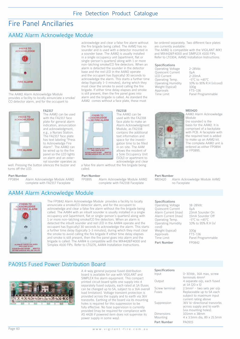
Page 60
Fire Detection Product Catalogue
w w w . v i g i l a n t -f i r e . c o m . a u
ME0420AAM2 Alarm Acknowledge Module (no sounder) is the basis for the AAM2. It is comprised of a backplate with PCB. A faceplate with the required text is added to make up an AAM2 kit. The complete AAM2 unit is ordered as either FP0894 or FP0895.
The AAM2 Alarm Acknowledge Module provides a facility to locally annunciate a smoke/CO detector alarm, and for the occupant to
acknowledge and clear a false fire alarm without the fire brigade being called. The AAM2 has no sounder and is used with a detector mounted in a sounder base. The AAM2 is usually installed in a single occupancy unit (apartment, flat or single-person’s quarters) along with 1 or more non-latching smoke/CO fire detectors. When an alarm is detected the sounder in the detector base and the red LED in the AAM2 operate and the occupant has (typically) 30 seconds to acknowledge the alarm. This starts a further time delay (typically 1-3 minutes), during which they must clear the smoke to avoid calling the fire brigade. If either time delay elapses and smoke is still present, then the fire panel goes into alarm and the brigade is called. As standard the AAM2 comes without a face plate, these must
be ordered separately. Two different face plates are currently available:The AAM2 is compatible with the VIGILANT MX1 and MX4428/F4000 and SIMPLEX 4100 FIPs. Refer to LT0304, AAM2 Installation Instructions.
FA2317The AAM2 can be used with the FA2317 face plate for general alarm indication, annunciation and acknowledgment, e.g., a Nurses Station. The FA2317 face plate has text labeling “Press to Acknowledge Fire Alarm”. The AAM2 can be wired up to the fire panel so the LED lights on alarm and an exter-nal sounder operates as
well. Pressing the button silences the buzzer and turns off the LED.
FA2318The AAM2 can be used with the FA2318 face plate to make an Alarm Acknowledgment Module, as FA2318 contains the additional text information and space for the investi-gation time to be filled in on-site. The AAM allows the resident of a Sole Occupancy Unit (SOU) or apartment to acknowledge and clear
a false fire alarm without the fire brigade being called.
SpecificationsOperating Voltage 2-28VdcQuiescent Current 0µALED Current 2-20mAOperating Temp. -5°C to +45°COperating Humidity 10% to 95% R.H (n/cond)Weight (typical) 100gApprovals FTS-136Time Limit Panel Programmable
AAM2 Alarm Acknowledge Module
Fire Panel Ancillaries
Part Number FP0894 Alarm Acknowledge Module AAM2 complete with FA2317 Faceplate
Part Number FP0895 Alarm Acknowledge Module AAM2 complete with FA2318 Faceplate
The FP0842 Alarm Acknowledge Module provides a facility to locally annunciate a smoke/CO detector alarm, and for the occupant to acknowledge and clear a false fire alarm without the fire brigade being called. The AAM4 with an inbuilt sounder is usually installed in a single occupancy unit (apartment, flat or single-person’s quarters) along with 1 or more non-latching smoke/CO fire detectors. When an alarm is detected the inbuilt sounder and red LED in the AAM4 operate and the occupant has (typically) 30 seconds to acknowledge the alarm. This starts a further time delay (typically 1-3 minutes), during which they must clear the smoke to avoid calling the fire brigade If either time delay elapses and smoke is still present, then the fire panel goes into alarm and the brigade is called. The AAM4 is compatible with the MX4428/F4000 and Simplex 4100 FIPs. Refer to LT0276, AAM4 Installation Instructions.
AAM4 Alarm Acknowledge ModuleSpecificationsOperating Voltage 18-28VdcQuiescent Current 0µAAlarm Current (max) 23mA Sounder OnAlarm Current (max) 15mA Sounder OffOperating Temp. -5°C to +45°COperating Humidity 10% to 95% R.H (n/cond)Weight (typical) 100gApprovals FTS-136Time Limit Panel ProgrammablePart Number FP0842
Part Number ME0420 Alarm Acknowledge Module AAM2 no Faceplate
PA0915 Fused Power Distribution BoardA 4-way general purpose fused distribution board is available for use with VIGILANT and SIMPLEX fire alarm equipment. This compact printed circuit board splits one supply into 4 separately fused outputs, each rated at 1A (fuses can be changed up to 5A, subject to a 16A overall load limitation). Voltage transient protection is provided across the supply and to earth via 36V tranzorbs. Earthing of the board via its mounting holes is required for this suppression to be fully effective. No fuse supervision is currently provided (may be required for compliance with AS 4428 if powered item does not supervise its power supply in some way).
SpecificationsInput 0-30Vdc, 16A max, screw terminals 4mm2
Output 4 separate o/p, each fused at 1A (20 x 5)Screw terminal 2.5mm2 – two sets per o/pFuses Replaceable up to 5A each subject to maximum input current rating aboveSuppression 36V bi-directional tranzorbs across supply and to earth (via mounting holes).Dimensions 101mm x 38mmMounting 4 x 3.5mm dia, 89 x 25.5mmPart Number PA0915

Page 61
Fire Detection Product Catalogue
w w w . s i m p l e x - f i r e . c o m . a u
ME0060 7U Inner Display Door
LM0339 Loom FRC 26W Kybd to 1st Disp, 200 mmME0457 4U Inner Display Door
FP1002 16Z Display PCB
Additional LED Display - 7U DoorIncreasing the number of LED zone displays on either an F3200 or MX4428 requires 1 x ME0060 plus 1 x FZ3031 plus up to 3 x FP0475 (as required). The 7U Display Door mounts directly below the standard 4U LCD. The Zone LEDs are Alarm (Red); Fault (Yellow); Isolated (Yellow) with a Zone name space of 10mm x 60mm per zone on a paper label; eg. 2 lines of 23 characters at 10 per inch.
Additional LED Display - 4U DoorIncreasing the number of LED zone displays on either an MX1 F3200 or MX4428 requires 1 x ME0457 plus 1 x FP1002 plus up to 4 x FP1002 (as required.) The 4U Display Door mounts directly below the standard 4U LCD. The Zone LEDs are Alarm (Red) and Isolate/Disable (Yellow). A Zone name space of 9mm x 44mm per zone on a paper label; e.g. 1 line of 12 characters at 5mm high (23 characters at 3mm high).
LED Display Extender Modules
F3200/NDU/NLDU
MX4428 MX1
Controller to highest numbered LED Display Board
LM0092 LM0295 or LM0056
LM0092 orLM0339*
Controller connector
J13 on Controller Board
J6 on Main Board
J2 on LCD/Keyboard
Connect additional 4U LED Display Door
LM0056 LM0056 LM0056 or LM0291*
Inter-connect LED Display Boards
LM0291 LM0291 LM0291*
* LM0291 and LM0339 are included with FP1002
FP1002 FP0475
Dimensions 144 x 52 mm 250 x 97 mm
Electrical Electrically identical; FP1002 uses 1/3 of the power
End-of-Chain link
Not Required Required
Separate Fault LED
No Yes
External Output No Yes
Table 1. Cables Required for 4U LED Display Door Table 2. LED Display Module Comparison
Part Numbers FP0475 Display Extender Kit (includes PA0454, LM0046, standoffs, power leads, diffuser, Zone name label master)FP1002 4U 16 Zone LED Display PCB (includes PCB, LM0291 FRC, LM0339 FRC, mounting hardware)FZ3031 Display Extender Kit (includes FP0475, LM0092 in lieu of LM0046) - use as first (LHS) displayME0060 7U Inner Display Door 1901-75 (includes M6 fasteners). It mounts up to 4x 16 Zone LED display boards.PA0454 7U 16 Zone LED Display PCBME0457 4U Inner Display Door mounts up to 5x FP1002 LED Display BoardsLM0044 FRC 26W Style B 200mmLM0045 FRC 26W Style B 5000mmLM0046 FRC 26W Style B 500mmLM0049 FRC 26W Style B 250mmLM0056 FRC 26W Style B, 1400 mmLM0092 FRC 26W Kybd to 1st Disp, 1100 mmLM0291 FRC 26W Style B, 230 mmLM0295 FRC 26W Style B, 700 mmLM0339 FRC 26W Kybd to 1st Disp, 200 mm
FP0475 Display Extender Kit includes: PA0454 16Z Display PCB, LM0046, standoffs, power leads, diffuser, Zone name label master. LM0092 Loom FRC 26W Kybd to First Display 1.1m shown.
PA0730 General Purpose Relay BoardSpecifications PA0730Operating Voltage 24Vdc (±20%)Quiescent Current nilOperating Current 12mARelay Contact 2A @ 30Vdc resistive(per pole) 1A @ 30Vdc inductive 1A @ 30 Vac inductiveAmbient Temp -5°C to +45°CRelative Humidity 0 to 95% (non/cond)Dimensions (mm) 40 x 41Weight 0.05kgFPANZ Listed VF/662Part Number PA0730
The 24V PA0730 two pole changeover contact general purpose relay board may be used in either of two modes: 1) Direct Operation: The relay will operate when the rated voltage is applied to the +ve and -ve terminals.2) SIG+ Input: Cutting link LK1 will allow the relay to operate if a positive voltage between 3.5V and 30Vdc is applied to the SIG+ terminal. SIG+ is a low current input so it may be driven by a logic level signal.In this mode the relay board must have constant power to the + and - terminals. The relay board also provides visual feedback with an LED illuminated whenever the relay is energised. Two sets of changeover contacts are available at screw terminals on the relay board.

Page 62
Fire Detection Product Catalogue
w w w . v i g i l a n t -f i r e . c o m . a u
Cabinets and Cabinet Accessories
VIGILANT 19inch Rack Cabinet Range
FP0576 Empty Battery Box Dimensions 440x550x211mm (HWD)Battery Capacity 2x80Ah / 6x40Ah
CabinetsFP0556 F3200, Empty Cab, c/w windowFP0557 F3200, Empty Cab, c/w blank doorFP0576 F3200, Battery Box FP0584 F3200, Small Empty Cab, full window FP1030 MX1 15U Empty Cab c/w wndw TitaniaFP1084 MX1 15U Empty Cab wndw Tit.,no MCPME0250 20Ux200 IP65 990x630x260 (HWD)ME0341 Rack Cab, 20Ux310 IP65 ME0260 Rack Cab, 20Ux310, 304 S/S IP65ME0270 Rack Cab, 30Ux310 IP65ME0280 Rack Cab, 40Ux310 IP65ME0252 Rack Cab, 18U 135, Full Wndw ME0253 Rack Cab, 18U 310, Full Wndw ME0268 Rack Cab, 21U 310, Full Wndw ME0254 Rack Cab, 28U 135, Full Wndw ME0255 Rack Cab, 28U 310, Full Wndw ME0256 Rack Cab, 40U 135, Full Wndw ME0257 Rack Cab, 40U 310, Full Wndw ME0262 Rack Cab, 18U 135, Blank Door ME0263 Rack Cab, 18U 310, Blank Door ME0269 Rack Cab, 21U 310, Blank Door ME0264 Rack Cab, 28U 135, Blank Door ME0265 Rack Cab, 28U 310, Blank Door ME0266 Rack Cab, 40U 135, Blank DoorME0267 Rack Cab, 40U 310, Blank DoorME0088 IOR Cabinet 449x494x82mm (HWD)ME0251 Small QE90, 21U 310, Full Wndw, CrmME0261 Small QE90, 21U310, Blank, CreamCabinet DoorsFA1262 Outer Door, Blank 8UME0336 Outer Door Full Window 15UFA1218 Outer Door Perspex 15UFA1228 Outer Door Blank 15UME0273 Outer Door Full Window 21UME0283 Outer Door Blank 21UME0274 Outer Door Full Window 28UME0276S Outer Door Full Window 40UME0286 Outer Door Blank 40UFA2113 Outer Door Perspex 40UStandard Cabinet SizesPart No Units DimensionFP0584 8U 440x550x211FP0556 15U 750x550x211ME0252 18U 885x575x205 (135 Deep)ME0253 18U 885x575x380 (310 Deep)ME0268 21U 1050x575x312 (310 Deep)ME0254 28U 1330x575x165 (135 Deep)ME0255 28U 1330x575x340 (310 Deep)ME0256 40U 1865x575x165 (135 Deep)ME0257 40U 1865x575x310 (310 Deep)Special Cabinet SizesME0250 20U IP65 990x630x260 (200 Dp)ME0260 20U S/S IP65 990x630x370 (310 Dp)ME0341 20U IP65 990x630x370 (310 Dp)ME0270 30U IP65 1435x630x370 (310 Dp)ME0280 40U IP65 1879x630x370 (310 Dp)
FZ9028 3U WA/Cube ASE Bracket & Loom
FP0937 4U WA/Cube ASE Bracket & Loom
FP1093 6U NT Brigade Bracket & Loom - Simplex
FP0935 4U ASE Bracket & Loom
AccessoriesHW0202 Block, Hinge Set 6mmKT0199 3U Centaur ASE BracketKT0212 3U 2xV-Modem/ASE DoorKT0419 Kit, Document Holder Stick On 3UFP0935 4U ASE Door Kit 4100ES-S1FP0937 4U WA/Cube ASE Door Kit 4100ES-S1FP1092 6U NT Brigade Door Kit Vigilant greyFP1093 6U NT Brigade Door Kit Simplex blackFZ9037 7U Hinged Door with Document HolderFZ9028 3U WA/Cube ASE Bracket & LoomME0258 1919-21-2 Rack Cab 1U Shelf 135 DPME0259 1919-21-1 Rack Cab 1U Shelf 310 DPME0512K 4100ESi Cube ASE & Mic kit (uses 6 slots of a 7U display door - black)ME0513K 4100ESi Centaur11 ASE & Mic kit (uses 6 slots of a 7U display door (black)NT0030 Nut, Cage M6 Zinc PlatedSC0058 Screw, Machine Pan/Pozi M6x12 ZPWA0008 Washer Flat M6 12mm ODx1.2mm Thk
FP0556 MX4428/F3200 15U Cabinet only Dimensions 750x550x211mm (HWD)
ME0268 21U (Cabinet only) Dimensions 1050x575x310mm (HWD)ME0351 21U (Cabinet only with QE90 Module Mounting Studs)
Blank Panels (include 19” rack fixing hardware)FZ9002 7U Blank Hinged Inner Door (312mm)FZ9003 6U Blank Panel Acrylic (266mm)FZ9004 4U Blank Panel (178mm)FZ9005 3U Blank Panel (134mm)FZ9006 2U Blank Panel (89mm)FZ9007 1U Blank Panel (45mm)FZ9015 5U Blank Panel (223mm)FZ9016 6U Blank Panel (267mm)FA1227 9.5U Blank Panel (420mm)FA1852 QE90 6U Smoked Perspex (266mm)FA2017 QE90 5.5U Blank Plate (244mm)FA2376 4100U 9U Display Trim
SW0018 3 Position keyswitch - incl. 003 keys
HW0040 Cam-Lock - includes 003 keysHW0226 Key only - 003 style
Gear PlatesFA1185 1901-47, F4000 Std 450x460FA2040 1901-193, F4k Rack Basic 540x460FA1984 1901-190, F4k 18U 770x482x180FA1983 1901-189, F4k 18U S’less 770x483FA1199 1901-101, F4k Large 1200x483x180FA1366 1901-181, S’less, Large 1200x483FA1267 1931-69, F3200 Std 480x460FA1846 699-053, QE90 480x489x175 *FA1833 699-052, QE90 Std 729x489x175 **FA2019 699-232, QE90 SECP Batt Brkt
* To suit cabinet ≥ 18U** To suit cabinet ≥ 28U
Flush Surrounds (cream wrinkle)FA1299 Flush Surround for 8U CabinetFA1235 Flush Surround for 15U CabinetFA1929 Flush Surround for 18U CabinetFA2031 Flush Surround for 21U CabinetFA1930 Flush Surround for 28U CabinetFA1931 Flush Surround for 40U Cabinet

Page 63
Fire Detection Product Catalogue
w w w . s i m p l e x - f i r e . c o m . a u
CAPACITY
A
F3200
8U
IP30
F3200
15U
IP30
20U IP65
200
Deep
20U IP65
310
Deep
30U IP65
310
Deep
40U IP65
310
Deep
18U
135 Deep
IP30
18U
310
Deep
IP30
21U
310
Deep
IP30
28U
135 Deep
IP30
28U
310
Deep
IP30
40U
135 Deep
IP30
40U
310
Deep
IP30
CABINET
PART NoFP0584 FP0556 ME0250
ME0260 (SS)
ME0341ME0270 ME0280 ME0252 ME0253 ME0268 ME0254 ME0255 ME0256 ME0257
Blank Door
CabinetFP0576 FP0557 — — — — ME0262 ME0263 ME0269 ME0264 ME0265 ME0266 ME0267
B
Overall Height
(mm)
440 750 990 990 1435 1879 885 885 1050 1330 1330 1865 1865
C
Internal Depth
(mm)
177 177 196 306 306 306 135 310 310 135 310 135 310
D
Cabinet Depth
(mm)
183 183 200 310 310 310 165 340 312 165 340 165 340
E
Overall Depth
(mm)
211 211 260 370 370 370 205 380 355 205 380 205 380
F
Window
Height (mm)
222 575 796 796 1241 1740 793 793 940 1237 1237 1771 1771
G
Window
Width (mm)
431 431 435 435 435 435 440 440 440 440 440 440 440
H
Cabinet
Width (mm)
550 550 630 630 630 630 575 575 575 575 575 575 575
Window
MaterialAcrylic Acrylic Glass Glass Glass Glass Acrylic Acrylic Acrylic Acrylic Acrylic Acrylic Acrylic
Note: “DEEP” in description refers to Internal Depth (dimension “C” above)
40U Cabinet
Front View
Cabinet Size Table
28U Cabinet 18U Cabinet
Top View - 135 Deep Cabinet
Top View - 310 Deep Cabinet
003 Key Lock
Dimpled Mounting
Holes (Ø6.5)
M8x20 Studs for
Gear Plate Mounting
Top View
Note that the IP65 Cabinet range are finished in off-white gloss powdercoat. All other cabinets are cream wrinkle finish.

Page 64
Fire Detection Product Catalogue
w w w . v i g i l a n t -f i r e . c o m . a u
15U Sideless 1965-1
MX4428 Main Board Mounting
IOR & Termination Board Mounting
IOR MountingADR/MPR Mounting
MX4428 6A PSU Brick Mounting
MX4428 2.5A PSU Mounting
15U Sideless 1965-2
MX4428 5A PSU Mounting
MX4428 Main Board Mounting
ADR/MPR Mounting T-GEN 50 & MXP Mounting
18U Sideless 1965-4
MX4428 Main Board Mounting
IOR & Termination Board Mounting
IOR MountingADR/MPR Mounting
MX4428 6A PSU Brick Mounting
MX4428 5A PSU Mounting
18U Sided 1965-3
MX4428 Main Board and RZDU/RS232 I/F Board Mounting
IOR & Termination Board Mounting
IOR Mounting
ADR/MPR Mounting
MX4428 5A PSU Mounting
MX4428 6A PSU Brick Mounting
Gear Plate Utilisation (examples)
FA1185 MX4428 Standard Gear Plate
FA2040 MX4428 Basic Gear Plate
FA1983 MX4428 18U Sideless Gear Plate
FA1984 MX4428 18U Sided Gear Plate
15U Sideless 1965-2
MX4428 5A PSU Mounting
MX4428 Main Board Mounting
ADR/MPR Mounting T-GEN 50 & MXP Mounting
15U Sideless 1965-1
MX4428 Main Board Mounting
IOR & Termination Board Mounting
IOR MountingADR/MPR Mounting
MX4428 6A PSU Brick Mounting
MX4428 2.5A PSU Mounting
18U Sideless 1965-4
MX4428 Main Board Mounting
IOR & Termination Board Mounting
IOR MountingADR/MPR Mounting
MX4428 6A PSU Brick Mounting
MX4428 5A PSU Mounting
18U Sided 1965-3
MX4428 Main Board and RZDU/RS232 I/F Board Mounting
IOR & Termination Board Mounting
IOR Mounting
ADR/MPR Mounting
MX4428 5A PSU Mounting
MX4428 6A PSU Brick Mounting
18U Sided 1965-3
MX4428 Main Board and RZDU/RS232 I/F Board Mounting
IOR & Termination Board Mounting
IOR Mounting
ADR/MPR Mounting
MX4428 5A PSU Mounting
MX4428 6A PSU Brick Mounting
18U Sided 1965-3
MX4428 Main Board and RZDU/RS232 I/F Board Mounting
IOR & Termination Board Mounting
IOR Mounting
ADR/MPR Mounting
MX4428 5A PSU Mounting
MX4428 6A PSU Brick Mounting
18U Sided 1965-3
MX4428 Main Board and RZDU/RS232 I/F Board Mounting
IOR & Termination Board Mounting
IOR Mounting
ADR/MPR Mounting
MX4428 5A PSU Mounting
MX4428 6A PSU Brick Mounting
18U Sided 1965-3
MX4428 Main Board and RZDU/RS232 I/F Board Mounting
IOR & Termination Board Mounting
IOR Mounting
ADR/MPR Mounting
MX4428 5A PSU Mounting
MX4428 6A PSU Brick Mounting
15U Sideless 1965-1
MX4428 Main Board Mounting
IOR & Termination Board Mounting
IOR MountingADR/MPR Mounting
MX4428 6A PSU Brick Mounting
MX4428 2.5A PSU Mounting

Page 65
Fire Detection Product Catalogue
w w w . s i m p l e x - f i r e . c o m . a u
28U Sided 1965-5
MX4428 Main Board and RZDU/RS232 I/F Board Mounting
IOR Termination Board Mounting
IOR MountingADR/MPR Mounting
MX4428 6A PSU Brick Mounting
MX4428 5A PSU Mounting
28U Sideless 1965-6
MX4428 Main Board and RZDU/RS232 I/F Board Mounting
IOR Mounting F3200 Card Frame Mounting
ADR/MPR MountingMX4428 6A PSU Brick Mounting
MX4428 5A PSU Mounting
FA1199 MX4428 28U Sided Gear Plate
FA1366 MX4428 28U Sideless Gear Plate
Gear Plate Utilisation (examples)

Page 66
Fire Detection Product Catalogue
w w w . v i g i l a n t -f i r e . c o m . a u
LM0041 MX4428/F4000 Cable Programming Port to DB9F serial 1888-58LM0042 MX4428/F4000 Cable Programming Port to DB25F serial 1888-62
LM0185 MX4428 Molex to CMOS/RS-232 1901-214
LM0195 4100 MAPNET Power Harness
Looms and Cables
Looms and Cables
LM0053 Loom FRC 20W Style A 0.3m
LM0092 Loom FRC 26W F3200 MkII Controller to First Display 1.1m
LM0049 Loom FRC 26W Style B 0.25m
LM0047 Loom FRC 26W Style D 1.3mQE90 TRAN8872
LM0076 Programming DB9F to DB9F Null Modem (MX1, QE90 ECM, ADU)
LM0065 RS-485 Comms 10W FRC to DB9
733-794 4100 Download Port Cable 10W FRC to DB9
LM0339 Loom FRC 26W, MX1 Keyboard to First Display, 200 mm
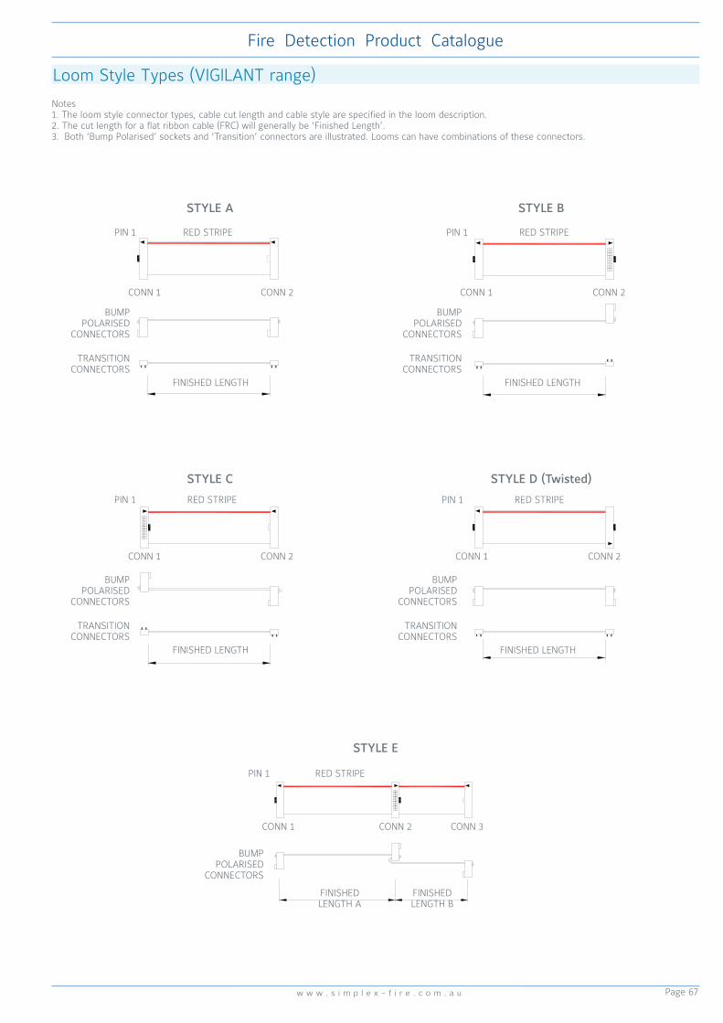
Page 67
Fire Detection Product Catalogue
w w w . s i m p l e x - f i r e . c o m . a u
STYLE E
STYLE C STYLE D (Twisted)
STYLE A STYLE B
Loom Style Types (VIGILANT range)
Notes1. The loom style connector types, cable cut length and cable style are specified in the loom description.2. The cut length for a flat ribbon cable (FRC) will generally be ‘Finished Length’.3. Both ‘Bump Polarised’ sockets and ‘Transition’ connectors are illustrated. Looms can have combinations of these connectors.
PIN 1
CONN 1 CONN 2
FINISHED LENGTH
TRANSITION CONNECTORS
BUMP POLARISED
CONNECTORS
RED STRIPE PIN 1
CONN 1 CONN 2
FINISHED LENGTH
TRANSITION CONNECTORS
BUMP POLARISED
CONNECTORS
RED STRIPE
PIN 1
CONN 1 CONN 2
FINISHED LENGTH
TRANSITION CONNECTORS
BUMP POLARISED
CONNECTORS
RED STRIPE PIN 1
CONN 1 CONN 2
FINISHED LENGTH
TRANSITION CONNECTORS
BUMP POLARISED
CONNECTORS
RED STRIPE
PIN 1
CONN 1 CONN 2
BUMP POLARISED
CONNECTORS
RED STRIPE
CONN 3
FINISHED LENGTH B
FINISHED LENGTH A
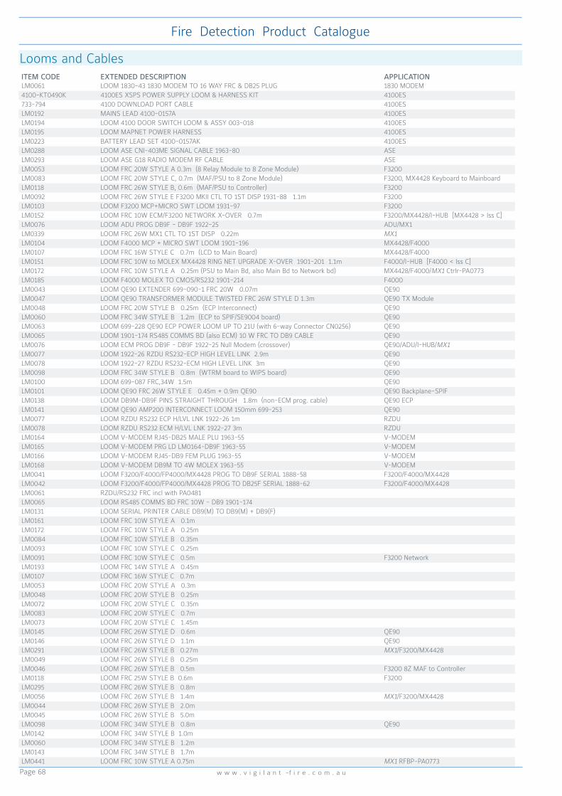
Page 68
Fire Detection Product Catalogue
w w w . v i g i l a n t -f i r e . c o m . a u
Looms and CablesITEM CODE EXTENDED DESCRIPTION APPLICATIONLM0061 LOOM 1830-43 1830 MODEM TO 16 WAY FRC & DB25 PLUG 1830 MODEM4100-KT0490K 4100ES XSPS POWER SUPPLY LOOM & HARNESS KIT 4100ES733-794 4100 DOWNLOAD PORT CABLE 4100ESLM0192 MAINS LEAD 4100-0157A 4100ESLM0194 LOOM 4100 DOOR SWITCH LOOM & ASSY 003-018 4100ESLM0195 LOOM MAPNET POWER HARNESS 4100ESLM0223 BATTERY LEAD SET 4100-0157AK 4100ESLM0288 LOOM ASE CNI-403ME SIGNAL CABLE 1963-80 ASELM0293 LOOM ASE G18 RADIO MODEM RF CABLE ASELM0053 LOOM FRC 20W STYLE A 0.3m (8 Relay Module to 8 Zone Module) F3200LM0083 LOOM FRC 20W STYLE C, 0.7m (MAF/PSU to 8 Zone Module) F3200, MX4428 Keyboard to MainboardLM0118 LOOM FRC 26W STYLE B, 0.6m (MAF/PSU to Controller) F3200LM0092 LOOM FRC 26W STYLE E F3200 MKII CTL TO 1ST DISP 1931-88 1.1m F3200LM0103 LOOM F3200 MCP+MICRO SWT LOOM 1931-97 F3200LM0152 LOOM FRC 10W ECM/F3200 NETWORK X-OVER 0.7m F3200/MX4428/I-HUB [MX4428 > Iss C]LM0076 LOOM ADU PROG DB9F - DB9F 1922-25 ADU/MX1LM0339 LOOM FRC 26W MX1 CTL TO 1ST DISP 0.22m MX1LM0104 LOOM F4000 MCP + MICRO SWT LOOM 1901-196 MX4428/F4000LM0107 LOOM FRC 16W STYLE C 0.7m (LCD to Main Board) MX4428/F4000LM0151 LOOM FRC 10W to MOLEX MX4428 RING NET UPGRADE X-OVER 1901-201 1.1m F4000/I-HUB [F4000 < Iss C]LM0172 LOOM FRC 10W STYLE A 0.25m (PSU to Main Bd, also Main Bd to Network bd) MX4428/F4000/MX1 Ctrlr-PA0773LM0185 LOOM F4000 MOLEX TO CMOS/RS232 1901-214 F4000LM0043 LOOM QE90 EXTENDER 699-090-1 FRC 20W 0.07m QE90LM0047 LOOM QE90 TRANSFORMER MODULE TWISTED FRC 26W STYLE D 1.3m QE90 TX ModuleLM0048 LOOM FRC 20W STYLE B 0.25m (ECP Interconnect) QE90LM0060 LOOM FRC 34W STYLE B 1.2m (ECP to SPIF/SE9004 board) QE90LM0063 LOOM 699-228 QE90 ECP POWER LOOM UP TO 21U (with 6-way Connector CN0256) QE90LM0065 LOOM 1901-174 RS485 COMMS BD (also ECM) 10 W FRC TO DB9 CABLE QE90LM0076 LOOM ECM PROG DB9F - DB9F 1922-25 Null Modem (crossover) QE90/ADU/I-HUB/MX1LM0077 LOOM 1922-26 RZDU RS232-ECP HIGH LEVEL LINK 2.9m QE90LM0078 LOOM 1922-27 RZDU RS232-ECM HIGH LEVEL LINK 3m QE90LM0098 LOOM FRC 34W STYLE B 0.8m (WTRM board to WIPS board) QE90LM0100 LOOM 699-087 FRC,34W 1.5m QE90LM0101 LOOM QE90 FRC 26W STYLE E 0.45m + 0.9m QE90 QE90 Backplane-SPIFLM0138 LOOM DB9M-DB9F PINS STRAIGHT THROUGH 1.8m (non-ECM prog. cable) QE90 ECPLM0141 LOOM QE90 AMP200 INTERCONNECT LOOM 150mm 699-253 QE90LM0077 LOOM RZDU RS232 ECP H/LVL LNK 1922-26 1m RZDULM0078 LOOM RZDU RS232 ECM H/LVL LNK 1922-27 3m RZDULM0164 LOOM V-MODEM RJ45-DB25 MALE PLU 1963-55 V-MODEMLM0165 LOOM V-MODEM PRG LD LM0164-DB9F 1963-55 V-MODEMLM0166 LOOM V-MODEM RJ45-DB9 FEM PLUG 1963-55 V-MODEMLM0168 LOOM V-MODEM DB9M TO 4W MOLEX 1963-55 V-MODEMLM0041 LOOM F3200/F4000/FP4000/MX4428 PROG TO DB9F SERIAL 1888-58 F3200/F4000/MX4428LM0042 LOOM F3200/F4000/FP4000/MX4428 PROG TO DB25F SERIAL 1888-62 F3200/F4000/MX4428LM0061 RZDU/RS232 FRC incl with PA0481LM0065 LOOM RS485 COMMS BD FRC 10W - DB9 1901-174LM0131 LOOM SERIAL PRINTER CABLE DB9(M) TO DB9(M) + DB9(F)LM0161 LOOM FRC 10W STYLE A 0.1mLM0172 LOOM FRC 10W STYLE A 0.25mLM0084 LOOM FRC 10W STYLE B 0.35mLM0093 LOOM FRC 10W STYLE C 0.25mLM0091 LOOM FRC 10W STYLE C 0.5m F3200 NetworkLM0193 LOOM FRC 14W STYLE A 0.45mLM0107 LOOM FRC 16W STYLE C 0.7mLM0053 LOOM FRC 20W STYLE A 0.3mLM0048 LOOM FRC 20W STYLE B 0.25mLM0072 LOOM FRC 20W STYLE C 0.35mLM0083 LOOM FRC 20W STYLE C 0.7mLM0073 LOOM FRC 20W STYLE C 1.45mLM0145 LOOM FRC 26W STYLE D 0.6m QE90LM0146 LOOM FRC 26W STYLE D 1.1m QE90LM0291 LOOM FRC 26W STYLE B 0.27m MX1/F3200/MX4428LM0049 LOOM FRC 26W STYLE B 0.25mLM0046 LOOM FRC 26W STYLE B 0.5m F3200 8Z MAF to ControllerLM0118 LOOM FRC 25W STYLE B 0.6m F3200LM0295 LOOM FRC 26W STYLE B 0.8mLM0056 LOOM FRC 26W STYLE B 1.4m MX1/F3200/MX4428LM0044 LOOM FRC 26W STYLE B 2.0mLM0045 LOOM FRC 26W STYLE B 5.0mLM0098 LOOM FRC 34W STYLE B 0.8m QE90LM0142 LOOM FRC 34W STYLE B 1.0mLM0060 LOOM FRC 34W STYLE B 1.2mLM0143 LOOM FRC 34W STYLE B 1.7mLM0441 LOOM FRC 10W STYLE A 0.75m MX1 RFBP-PA0773

Page 69
Fire Detection Product Catalogue
w w w . s i m p l e x - f i r e . c o m . a u
FZ9012 7U Panel with 15 AS 1668 Fan Controls Drilled
AS1668 Control Module Kits
AS1668 Controls and Gas Controls
MX4428The AS 1668 modules/kits consist of small PCBs that are fitted with the required components for several different AS 1668 control and indication configurations.A three position rotary switch gives control of the appropriate fan, by selection of OFF, AUTO, or ON (from left to right). Three LEDs give indication of STOP, FAULT, and RUN conditions. These are coloured green, yellow, and red respectively. For maximum flexibility, a number of common AS 1668 type control circuits can be achieved by using KT0113 module using different wiring configurations, and/or by minimal PCB modification (i.e. the cutting of two components). While the kits were primarily developed to simplify factory assembly of custom panels with AS 1668 controls, they are available to purchase for fitting to panels in the field. Refer to the Product Bulletins PBG0015C and PBG0145C and manuals LT0159, LT0368 and LT0438 for further information regarding AS 1668 kits.
Part NumbersFZ9011 7U Door 19” Rack, 5 x AS 1668 ControlsFZ9012 7U Door 19” Rack, 15 x AS 1668 ControlsFZ9036 2U Door 19” Rack, 5 x AS 1668 ControlsKT0113 Kit, 1945-1-3 AS 1668 Control Module Type 3 KT0512 Kit, 4 x AS 1668 + Common Master Control ModuleKT0478 Kit, AS 1668 5 way Fan Control Module
KT0113 Kit, AS 1668 Control Module Type 3
KT0478 Kit, AS 1668 5 way Fan Control ModuleIncludes PCB, 5x switch knobs and caps, 5x panel labels, 2x 26W FRC 2m cables, LT0368 instructions
FP1056 3U Panel with 12x AS1668 Fan Controls (MX1 only)
RJ45 (optional)RJ45 Cable
LM0590 Power Loom
LM0553 Interconnection FRC
LM0324 10W FRC
RJ45 (optional)
Inside Door 1
Inside Door 2
RJ45 To Next Door
MX1The FP1056 MX1 Fan Control Door Kit includes a 3U door fitted with 2 fan controls and a label set with sample common fan control labels. Each door can accommodate up to 12 fan controls using additional FP1057 Fan Control Expansion kits.This fan control solution has been assessed to the functional requirements of AS 7240.2-2004 and AS 4428.7-1999. It can provide up to 126 controls per MX1, by utilising FP1056 3U doors for each set of 12 controls. It features push buttons and LED indication for On/Off/Auto, with LED status indication for Run, Stop, Fault and Alarm.The controls can also provide convenient general purpose switches and indicators for ancillary functions such as drain valves, deluge control, and test switches. Each control can be configured to operate as a 3-position switch, 2-position switch, or 3-independant toggle or momentary switches.The control functions can be replicated across multiple MX1 panels on a network almost instantly. The panels work in parallel, with user control available at each panel. Additional Fan Control doors are interconnected using cables supplied. Up to 3 doors (36 controls) can be fitted in a 15U MX1 cabinet, with additional 15U or larger 28U or 40U cabinets available for more controls.The controls are easily configured for an MX1 using SmartConfig version 2.5.1 or above. This includes logic blocks to insert pre-defined AS 1668 smoke control functions. Labels for each control can be printed using SmartConfig. The fan controls can be added to existing MX1 systems by updating to MX1 firmware version 1.60 or above. This MX1 AS 1668 solution is not compatible with MX4428.
Part NumbersFP1056 MX1 3U 12x AS 1668 Controls (MX1 only)FP1057 MX1 2-Way AS 1668 Control Expansion KitFP1084 MX1 15U Full Window Empty Cabinet, TitaniaLB0672 AS 1668 Fan Control Zone Label Set

Page 70
Fire Detection Product Catalogue
w w w . v i g i l a n t -f i r e . c o m . a u
ME0441 4 Zone Gas Flood 7U Door
Gas Control Modules provide indication and control of 1-4 zones of gas extinguishing on F3200 and MX4428 CIE. They are pre-wired modules (requiring appropriate input/output modules). The modules have a 12 way screw terminal block for easy termination of the field wiring for the Local Gas Control Stations, gas discharged pressure switch, warning signs and gas release output. The connection for the Alert/Evacuate warning signs is a 2-wire polarity switched output that supports up to 10 AVI Mk2 units. All outputs can be supervised (this requires appropriate programming and configuring in the panel). The gas control modules provide LEDs for each gas zone to indicate:
• Gas Initiated (red) • Manual Release (red) • Gas Discharged (blue) • Gas Inhibited (yellow) • Gas Isolated (yellow) • System Inoperative (yellow)
A Gas Discharge Isolate switch that physically isolates both poles of the gas release actuator output is also provided for each gas zone.
FP0570 Local Gas Control Station - Automatic. Local Gas Control Stations (LGCS) are used in gaseous fire extinguishing systems to provide local area manual control of a release. The automatic version includes a Gas Inhibit switch, buzzer and LED, whereas the manual version (FP0572) does not. The LGCS is fitted with a resettable no-break plastic frangible element.
Gas Control Modules
ME0440 3 Zone Gas Flood 7U Door and Loom
ME0442 1 Zone Gas Flood 1U Door and Loom
SpecificationsDimensions (mm) FP0570/2 192 x 124 x 82 (HWD) ME043x 7U - 485 x 312 (WH) ME0442 1U - 485 x 45 (WH)Part NumbersFP0570 1937-3-1 Local Gas Control Station - AutoFP0572 1937-3-2 Local Gas Control Station - ManualME0439 2 Zone Gas Flood 7U Door & LoomME0440 3 Zone Gas Flood 7U Door & LoomME0441 4 Zone Gas Flood 7U Door & LoomME0442 1 Zone Gas Flood 1U Door & LoomSW0122 Switch Toggle, LGCS, Locking
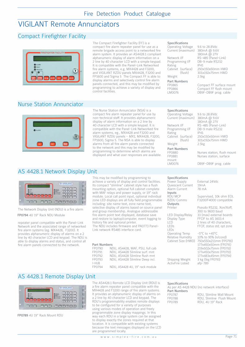
Page 71
Fire Detection Product Catalogue
w w w . s i m p l e x - f i r e . c o m . a u
Compact Firefighter FacilityThe Compact Firefighter Facility (FF) is a compact fire alarm repeater panel for use as a remote brigade access point to a networked fire alarm system. It provides an AS4428.1 compliant alphanumeric display of alarm information on a 2 line by 40 character LCD with a simple keypad. It is compatible with the Panel-Link Networked fire alarm systems, e.g. MX4428 and F3200, and VIGILANT RZDU panels MX4428, F3200 and FP1600 and Sigma 5 The Compact FF is able to display alarms and selectively control fire alarm panels connected, and this may be modified by programming to achieve a variety of display and control facilities.
SpecificationsOperating Voltage 9.6 to 28.8VdcCurrent (maximum) 380mA @ 9.6V 180mA @ 27VNetwork I/F RS-485 (Panel-Link)Programming I/F DB-9 male RS232Rating IP41Cabinet (surface) 250x150x50mm HWD (flush) 301x192x75mm HWDWeight 2.5kgPart NumbersFP0865 Compact FF surface mountFP0866 Compact FF flush mountLM0076 DB9F-DB9F prog. cable
VIGILANT Remote Annunciators
AS 4428.1 Network Display Unit
The Network Display Unit (NDU) is a fire alarm
repeater panel compatible with the Panel-Link Network and the associated range of networked fire alarm systems (eg. MX4428, F3200). It provides alphanumeric display of alarms on a 2 line by 40 character LCD and keypad. The NDU is able to display alarms and status, and control all fire alarm panels connected to the network.
This may be modified by programming to achieve a variety of display and control facilities. Its compact “slimline” cabinet style has a flush mounting option, optional full cabinet complete with MAF relays and power supply, or 19” rack module. Local call point input, optional individual zone LED displays are all fully field programmable including: site name text, zone name text, selective display of alarms based on source panel and group membership. Analogue addressable fire alarm point text displayed, database save and restore to laptop/computer, event logging to history file and optional printer. The NDU includes firmware and PA0773 Panel-Link network RS485 interface card.
SpecificationsPower Supply External 24VdcQuiescent Current 19mAAlarm Current 78 mA Inputs RDU MCP Supervised, 10k ohm EOLRZDU Comms F3200/F4000 compatibleOutputsPrinter Pseudo RS232, Xon/Xoff, 300 to 9600 baudLED Display/Relay 33 (max) external boardsDisplay Type FFCIF to AS 1603.4LCD 2 lines of 40 characters,LEDs FFCIF, status std; opt zone LEDsOperating Temp -5°C to +45°CRelative Humidity 10% to 95% (n/cond)Cabinet Size (HWD) 750x550x211mm (FP0790) 177x450x50mm (FP0791) 219x502x75mm (FP0792) 177x450x75mm (FP0793) 177x483x45mm (FP0794)Shipping Weight 3 kg (5kg FP0793)ActivFire Listed afp-789
FP0794 4U 19” Rack NDU Module
Part NumbersFP0790 NDU, AS4428, MAF, PSU, full cabFP0791 NDU, AS4428 Slimline surf. mntFP0792 NDU, AS4428 Slimline flush mntFP0793 NDU, AS4428 Slimline Deep incl. I-HUBFP0794 NDU, AS4428 4U, 19” rack module
The Nurse Station Annunciator (NSA) is a compact fire alarm repeater panel for use by non-technical staff. It provides alphanumeric display of alarm information on a 2 line by 40 character LCD with a simple keypad. It is compatible with the Panel-Link Networked fire alarm systems, eg., MX4428 and F3200 and VIGILANT RZDU panels - MX1, MX4428, F3200, FP1600, Sigma 5. The NSA is able to display alarms from all fire alarm panels connected to the network and this may be modified by programming to determine which alarms are displayed and what user responses are available.
Nurse Station AnnunciatorSpecificationsOperating Voltage 9.6 to 28.8VdcCurrent (maximum) 380mA @ 9.6V 180mA @ 27VNetwork I/F RS-485 (Panel-Link)Programming I/F DB-9 male RS232Rating IP41Cabinet (surface) 250x150x50mm HWD (flush) 301x192x75mm HWDWeight 2.5kgPart NumbersFP0880 Nurses station, flush mountFP0881 Nurses station, surface mount LM0076 DB9F-DB9F prog. cable
SpecificationsAs per AS 4428 NDU (no network interface)Part NumbersFP0787 RDU, Slimline Wall MountFP0788 RDU, Slimline Flush MountFP0789 RDU, 4U 19” Rack
AS 4428.1 Remote Display UnitThe AS4428.1 Remote LCD Display Unit (RDU) is a fire alarm repeater panel compatible with the MX4428 and F3200 range of fire alarm systems. It provides an alphanumeric display of alarms on a 2 line by 40 character LCD and keypad. The RDU’s programmability enables remote displays to be configured for a variety of purposes using various modes of operation and freely programmable zone display mappings. In this way each RDU in a large system can be assigned to display exactly the zones required at that location. It is compatible with existing systems because the text messages displayed on the LCD are programmed locally.
FP0789 4U 19” Rack Mount RDU

Page 72
Fire Detection Product Catalogue
w w w . v i g i l a n t -f i r e . c o m . a u
A network of Communications Control Units (CCU), called a CCUNet, can be used to connect multiple fire indicator panels and other supported devices to a central colour graphics system. This provides system wide control and annunciation of multiple fire detection systems. The CCU Network system and fire indicator panels are interconnected via dual redundant communication loops. The redundant network can be used to transparently route information around breakages and failures in the network. Event annunciation information from the fire panels is simultaneously routed via both the network CCUNet links.
Contact Johnson Controls when using CCU Networking, to ensure required system design and local standards criteria can be met.
CCU1 Communications Control Unit CCU3
CCU Networking
CCUNet
Simplex Network
Vigilant Network
Collective Panel
MXL Network
Dial-up Remote XL
Graphics Terminal
Pager
XL Graphics Terminal
The CCUNet has the capability to integrate numerous fire panel networks into one simple colour graphics interface.
Two methods of connecting CCU3/C-4100MB to SIMPLEX CIE
Two methods of connecting
CCU3/C-MXMB to VIGILANT MX4428 CIE
RS-485
XL GRAPHICS - C/S
CCU3 MODBUS SLAVE
CCU3
RS-232
MX4428 MX4428
MX4428 MX4428
RS-232
RS-485
CCU3 MODBUS SLAVE
CCU3
RS-232
SIMPLEX SIMPLEX
SIMPLEX SIMPLEX
RS-232
XL GRAPHICS - C/S

Page 73
Fire Detection Product Catalogue
w w w . s i m p l e x - f i r e . c o m . a u
Campus TCP/IP LAN or WAN
Fire & Security Centre
Remote Access Off-Campus
Squash Courts
Arts Building
Chemistry Building
Administration Building
Engineering & Maintenance Graphics
Global Graphics
Remote Graphics
Collective Panels
Simplex Panels
Vigilant Panels
MXL Panels
CCU3/E-HUB (422)
CCU3/C-HUB (422)
CCU3/C-HUB (422)
CCU3/M-PAGER (422)
CCUNet RS422 Redundant Loop
CCU3/M-RDM (422)
CCU3/C-4100 (422)
CCU3/C-4100 (422)
CCU3/C-4100 (422)
CCU3/F-NIM
CCU3/FST-F4000 (422)
CCU3/C4-F4000 (422)
CCU3/C4-F4000 (422)
CCU3/C-IO (422)
CCU3/C-IO (422)
CCU3/M-RDM (422)
PSTN
Example CCU System Diagram
This example shows several buildings on a university campus each with their own different fire panels, linked together via CCU3s to a CCUNet by 2 loops.

Page 74
Fire Detection Product Catalogue
w w w . v i g i l a n t -f i r e . c o m . a u
The VIGILANT QE90 Emergency Warning and Intercommunication System (EWIS) is designed to facilitate the orderly evacuation of a building in the event of an emergency. Integrating a flexible alarm and voice warning system with a dedicated emergency intercom system, the QE90 allows fire wardens or emergency services personnel to easily control and coordinate rapid building evacuation. QE90 meets the installation requirements of control and indicating equipment AS 1670.4, complies with equipment standard AS 2220.1 and supports the ISO 8201 T3 evacuation signal and strobe pattern.Features• Modular system is readily expandable • Networked systems for site-wide
interconnection (va copper, IP, fibre)• High level input from compatible FIPs• Choice of amplifers providing a wide range
of output power • Optional standby amplifiers with automatic
changeover • Visual alarm outputs • Factory programmable evacuation
sequences • Standard or custom voice messages (on-
site recordable) • Wiring supervision for amplifiers, speaker
lines, visual alarm outputs, FIP inputs, MCP inputs, power supplies, WIP circuits and ECP interconnection
• Duplicated communications links between equipment locations
• Music & non-emergency paging (with emergency override)
• Paging console available for non-emergency paging
• Non-emergency voice messages • Range of attractive 19” rack cabinets • QECOST Software Tool for Windows assists
the purchaser to specify and estimate the cost of a QE90 system
• Complies with EWIS standard AS 2220.1-1989
• Supports ISO8201 T3 evacuation signal• ActivFire listed afp-524 (Wormald)• ActivFire listed afp-1423 (Simplex)• FPANZ listing number VF/406 Factory-Programmable Facilities:• System configuration• Control relay outputs• Special cascade sequences• Warden zones• FIP/ emerg. call point input to zone mapping• Special digitised voice messages
Basic System Comprises:• Master Emergency Control Panel (MECP)
complete with full control facilities for both Emergency Warning and Emergency Intercommunication Systems
• Individual amplifier(s) per zone• Alert/ Evacuate tones with automatic digitised
voice message• Emergency public address• Standard automatic alarm cascade sequence• 3 WIP circuits per zone• Full supervision of speaker, WIP and strobe
lines with visual indications and sounder• Fire alarm inputs (one per zone)• Master background music (BGM) input• One BGM override output per amplifier• Integral 24 Volt battery charger• Storage for stand-by batteriesSite-Programmable Facilities:•Time delays - Alarm to Alert delay - Alert to Evacuate delay - Cascade step interval• Alert/ Evacuate/ PA groups• Background music zone selection• Individual zone isolation• Cascade enable/ disable• Service fault history recall/ clear• Redirection of Master WIP to field WIP
(optional)• Operation of non-emergency Paging Console
to perform WIP, BGM and general indication functions
Optional Extra Facilities:• More than 3 WIP circuits per zone• Secondary Emergency Control Panel(s)• Remote amplifier racks• Multiple FIP/ emergency call point inputs per
zone• Emergency call point inputs• 2 or 3-wire WIP/ emergency call point inputs• Strobe (visual) alarm outputs (T3 option)• Programmable relay outputs eg. - Evac fault - Any alarm - Fault or alarm - BGM override - Auto/ Man/ Isol. - WIP fault - WIP handset off hook• Emergency control panel lighting• Special cascade sequences• Automatic test sequence• Warden zones to alert wardens of alarm in
another area• Monitor zones to repeat the highest priority
signal that other nominated zones are receiving
• After-hours timer input to override cascade• Custom digitised voice messages
(multiple languages available)• Stand-by amplifier(s) with automatic
changeover• Distributed amplifier system• Inter-ECP WIP calls (for systems with more
than one ECP)• Remote WIP phones via derived circuits
(eg. fibre optics, radio)• WIP calls redirected to PABX, radio, or other WIP• Remote WIP control panel• Individual zone BGM inputs• Remote BGM control panel• Paging console programmable to also perform
WIP control and BGM control functions• Paging chimes• PABX paging interface• Local zone non-emergency paging• Event-logging printer• High-level data links• Networking (multiple media options)• Computer colour graphics SECP
Warning Systems
QE90 EWIS
SpecificationsPanel size 18U 21U 28U 40U Double 28U Double 40UHeight (mm) 885 1050 1330 1865 1330 1865Width (mm) 575 575 575 575 1150 1150MECP Depth (mm) 380 350 380 380 - 380SECP Depth (mm) 205 - 205 205 205 -Maximum number of zones with10W RMS Amps 8 20 20 40 - 8025W RMS Amps 6 10 10 20 - 4050W RMS Amps 4 10 10 20 - 40100W RMS Amps 2 5 5 10 - 20200W RMS Amps 2 2 2 4 - 8Amplifier configurations can be mixed 10, 25, 50, 100, 200 WattSpeaker Line Voltage 100V RMS at rated power outputWIP Zones (maximum) 10 18 20 42 - 90SECP Zones (maximum) 1-18 - 19-34 35-42 43-74 75-90Special or larger system configurations are available on requestCabinet Material 1.6mm mild steelCabinet Finish Baked epoxyColour Cream Wrinkle BFF998CW (special colours available on request)Operating Temperature -5°C to +45°COperating Humidity up to 95% RH (non condensing)Power Supply 230VAC +10% -11%, 50Hz
Spares - Refer to Page 121
A Combo QE90/Fire Panel is available. Contact Johnson Controls - Fire Detection for more information.Refer to page 125 for a sample QE90 Configuration Sheet. These must be submitted with each QE90 order for new panels and upgrades to existing panels. Refer to the relevant Johnson Controls Product Bulletin for guidance on completing the configuration sheet LT0613.
STOCK QE90 EWIS PANELS ARE AVAILABLE - QS1000 Supplied in a standard pre-programmed configuration suitable for applications requiring no more than 10 zones of 50 watts. They are aimed primarily at projects requiring a basic format and quick delivery.

Page 75
Fire Detection Product Catalogue
w w w . s i m p l e x - f i r e . c o m . a u
One or more Paging Consoles may be used with a QE90 system. Each console gives selective zone paging for up to 30 zones. These zones do not need to be the same as evacuation zones. Programming of any combinations of amplifiers into paging zones can be done by Johnson Controls - Fire Detection. If the system has more than 30 paging zones, then more than one Paging Console can be used at the same location to address the zones. The top of the Paging Console is removed to obtain access to the terminations. Only one microphone is required and it must be ordered separately.
Paging ConsoleSpecificationsPower Consumption <50mA (no zones select) <150mA (all zones select)Output Voltage 300 to 700mVMicrophone Voltage 1 to 100mVFrequency Response 100 to 10kHz ±3dBDistortion 10mV input, <2%Dimensions (HWD) 80 x 410 x 210mmWeight 4kgPart NumbersFP0539 Paging ConsoleSU0168 Gooseneck MicrophoneSU0169 Desktop MicrophoneFA1922 Paging Console Keypad
The SU0169 Paging microphone is a desktop dynamic microphone with a cardioid polar pattern. It features a short-off press to talk switch with an open-off type extra switch. It has low handling noise and a 600 ohm balanced output impedance. Compatible with the FP0539 Paging Console.
SU0169 Desktop MicrophoneSpecificationsPolar Pattern Cardioid (unidirectional)Output Impedance 600 Ohm balanced at 1kHzRated Sensitivity -58dB (1kHz, 0dB=1 V/Pa)Frequency Response 100 Hz to 10kHzCable 2 core shielded plus 2 coreCable Length 2.5mTermination 5 pin DIN plugDimensions (HWD) 215 x 100 x 150mmWeight 440gPart Number SU0169
The hand held dynamic microphone is fitted with a press-to-talk button. It is suitable for plugging into T-GEN 50 and QE90 to provide emergency PA and recording of digitised speech message. Two models are available; ME0213 has a DIN plug for use on older QE90 ECP9002, and ME0290 has a 4-Way flat plug for use on T-GEN 50 and QE90 ECP9702.
Hand Held Microphone with Press to Talk
The SU0168 Gooseneck Paging microphone is a dynamic microphone with a cardioid polar pattern. This elegant gooseneck microphone features smooth, brilliant sound with excellent ambient noise control and feedback rejection. Its screw base is suitable for mounting on equipment or permanent desk mounting . The slimline design of this microphone makes it ideal for custom paging consoles. It is supplied with 200mm flying leads and mounting kit for FP0539 Paging Console.
SU0168 Gooseneck MicrophoneSpecificationsPolar Pattern Cardioid (unidirectional)Output Impedance 600 Ohm balanced at 1kHzRated Sensitivity -80dB (1kHz, 0dB=1 V/Pa)Frequency Response 150Hz-12KHz Part Number SU0168
QE90 Ancillaries & Spares
Part Numbers ME0213 Microphone c/w DIN plug for old QE90 ECP9002 onlyME0290 Microphone c/w 4-way flat plug for T-GEN 50 and QE90 ECP9702 only
The PC-based Paging Console allows announcements to be made to up to 480 QE90 zones from a single Windows 2000/XP workstation, without requiring a separate physical paging console. The PC Paging Console interfaces a PC and microphone to the QE90 system. Control of paging individual or grouped evacuation zones is provided by software. Where the SU0168 microphone is used, the “Press To Talk’ button on the PC screen is used when a paging announcement is to be made. When using the SU0169 microphone it is necessary to use the PTT button on the microphone.
PC Paging ConsoleSpecificationsPlatform Windows 2000, XPCapacity Supports 480 QE90 zones and 10 user programmed groups of zonesConnection via audio and comms, PC required with 2 free RS232 portsDimensions (HWD) 310 x 238 x 105mmPart Number FP0902
ME0290 T-GEN/QE90 Mic. c/w 4-way Flat Plug (ECP9702 only)
ME0213 QE90 Mic. c/w DIN Plug (old ECP9002 only)

Page 76
Fire Detection Product Catalogue
w w w . v i g i l a n t -f i r e . c o m . a u
Designed specifically for use in VIGILANT Emergency Warning Systems, Warden Intercom Points (WIPs) are used to communicate between floor wardens and the main Emergency Evacuation Panel. When the handset is lifted, the WIP automatically rings the Emergency Evacuation Panel. When the Panel calls the WIP, the call tone sounds through the speaker in the body of the phone. When the handset is lifted, it automatically switches from the speaker in the body to the speaker in the handset. The FP0938 is compatible with the VIGILANT QE90 Emergency Intercommunication System.
FP0938 WIP PhoneSpecificationsCall Tone > 80dB 1W/1mAC Impedance 600 Ohms (off-hook)Screw Terminations To suit 0.75 to 1.5mm2 wireAmbient Temp -10°C to +50°CMaterial Red ABSDimensions (HWD) 215 x 70 x 70mmActivFire Listed afp-524Part NumbersFP0938 WIP PhoneC0612D External Speaker
The STI-CIS Analyser measures the speech intelligibility of a fire alarm evacuation signal. To measure overall speech intelligibility, the STI-CIS Analyser uses the STI measurement method to factor in the effects of the warning system, room acoustics (reverberations and echoes) and background noise.The STI-CIS Analyser comes equipped with its own microphone and LED display and has buttons to activate dBA and CIS measurements. There is provision for a PC interface (RS-232) for use with the STI-CIS Noise Effect Correction Software Tool.
STI-CIS Analyser and STI-CIS TALKBoxSpecifications - AnalyserAmbient Temp 0 to 50°CPower Supply 8 x AA batteries/AC adaptorDimensions (HWD) 410 x 250 x 70mm Weight 160g
Specifications - TALKBoxPower Supply1 12Vdc, 190mA via 8 x AA batteries or AC adaptor at 500mA (12Vdc, tip positive)SPL Output 0 dB to 100 dBA (STI-PA test tone)Ambient Temp 0 to 50°CDimensions (HWD) 470 x 360 x 180mm Weight 520gPart NumbersSTI-CIS Analyser & TALKBox Kit - 2 cases
1. 92dB(A) STI-PA tone out
The TALKBox is used to send the STI-PA test tone into the fire alarm warning system. It interfaces with the system through its microphone input. A line-level output is also available for systems with direct line inputs. The TALKBox comes equipped with its own CD player and speaker. The CD player has controls to Play, Rewind, and Fast Forward the CD with STI-PA test tone (supplied). However, pressing Play on the CD player is all that is required to play the test tone once you insert the STI-PA Test Tone CD into the CD player. Power is supplied to the TALKBox through a DC power supply (connected to the Ext. Power socket) or batteries. The TALKBox operates a minimum of 18 hours on eight AA alkaline batteries.
EA0412 is designed for use in Emergency Warning Systems, for protection of Warden Intercom Points (WIPs) against impact. The enclosure door is held closed by a magnetic catch. The enclosure is open-backed and is finished in red powder coat.
EA0412 WIP Phone Surface Mount EnclosureSpecificationsMaterial Mild SteelFinish Red powdercoatDimensions (HWD) 386 x 156 x 155mmWeight 1.8 kgPart Number EA0412
The SU0608 MCP is surface mounting, with a plastic coated glass element to ensure reliable, safe operation. It is coloured white (for EWIS applications) to be used where a fire alarm system does not exist. The call point is operated when the glass element is snapped, releasing the MCP’s micro switch, which signals an alarm to the EWIS panel. The element is snapped by pressing on its centre – a hammer, or other impact device, is not required.
SU0608 Evacuation Manual Call Point (White)SpecificationsMax Current 2A @ 30VdcContact Resistance 100mOhm. (max)Legend Emergency AlarmAmbient Temp -10 to +55°CRelative Humidity 95%(non cond.)Ingress Protection IP24DDimensions (HWD) 93 x89 x 60 mmPart NumbersSU0608 White MCP & Backbox515.001.025 Spare Glass (pk 5)

Page 77
Fire Detection Product Catalogue
w w w . s i m p l e x - f i r e . c o m . a u
QE90 Spares - Amplifiers
KT0519 200W Amplifier Module KitThe 200W amplifier comprises two PA0647 AMP200 PCB modules and one LM0141 FRC loom.
PA0650 EAMP9001 4x10W / 2x25W Zone Power Amplifier PCBDimensions 233x159x48mm
PA0690 HAMP93082x50W Amplifier Module
PA0688 1923-19 Microvac Mic Pre-Amp
QE90 Spares - Transformer Modules
PA0691 HTRN9308-12x50W Transformer ModulePA0695 HTMS9408-22x50W Transformer Music Switching Module
PA0692 HTRN9308-21x100W Transformer ModulePA0696 HTMS9408-21x100W Transformer Music Switching Module
PA0648 TRAN200200W TransformerTypical Dimensions 140x140x85mm, 3kg

Page 78
Fire Detection Product Catalogue
w w w . v i g i l a n t -f i r e . c o m . a u
QE90 Spares - Transformer Modules
PA0481 RZDU/RS232Interface 1901-100, includes LM0061
FP1071 SPIF9709 (PA0649) SECP Panel Interface PCB
FP1076 TRAN9705-4 (PA0794)2x25W Transformer Module c/w Relays incl. PA0650 EAMP9001
PA0795 TRAN9706-1 4x10W Transformer Module without Relays
FP1078 TRAN9705-2 (PA0792)4x25W Transformer Module c/w Relays incl. 2x PA0650 EAMP9001
QE90 Spares - Interface Modules
PA0657 SE9004 Signal Interface
QE90 Spares List - Major Components
FP1077 TRAN9706-2 (PA0796)4x10W Transformer Module c/w Relays incl. PA0650 EAMP9001
Refer to Page 121 for comprehensive list
PA0644 VIF0907VoIP Interface incl. 1x LM0448, 2x LM0552, DIN rail mntg h’ware
Part No. DescriptionPA0758 PCB Assy, QE90,EMUX9601, Multiplexer 16sec SpeechPA0759 PCB Assy, QE90,EMUX9601, Multiplexer 60sec SpeechPA0792 PCB Assy, TRAN9705-2, 4x25W Module c/w RelaysPA0794 PCB Assy, TRAN9705-4, 2x25W Module c/w RelaysPA0795 PCB Assy, TRAN9706-1, 4x10W Module Without RelaysPA0796 PCB Assy, TRAN9706-2, 4x10W Module c/w RelaysPA0916 PCB Assy, QE90 WTRM2000, WIP Termination (DIN)FP1068 PCB Assy, FIB8910 FIP/BGA Master (DIN Rail)FP1069 PCB Assy, FIPE9004 FIP/BGA Extender Module (DIN Rail)FP1070 PCB Assy, QE90 STRM9502 Strobe/relay Module (DIN Rail)FP1071 PCB Assy, SPIF9709 Secondary Panel Interface (DIN Rail)FP1072 PCB Assy, QE90 ECM9603 Evac Comms Module (DIN Rail)FP1073 Assy, WIP Slave + Termination PCBs Upgrade KitFP1074 Assy, 100W Amp + HTRAN9308-2 Upgrade KitFP1075 Assy, 2x50W Amp + HTRM9308-1 Upgrade KitFP1076 Assy, 2x25W Amp + TRAN9705-4 Upgrade KitFP1077 Assy, 4x10W Amp + TRAN9705-2 Upgrade KitFP1078 Assy, 4x25W Amp + TRAN9705-2 Upgrade KitFP1079 Assy, 200W Amp + TRAN200 Upgrade Kit
Part No. DescriptionFA2027 Keypad Only, ECP+2Z Keyboard,no Name,3 WIP per ZoneFA2029 Keypad Only, 8Z Extender Keyboard,3 WIP per ZoneFP1083 Display Assy 3 WIP per Zone, 8 Zone Extender incl. PCBME0207 ECP Assembly 3 WIP per Zone including ECPME0381 Assy, ECP + 2Z Keybd, 3WIP/Z Inner Door & Keypad only (>21u)ME0382 Assy, ECP 8Z Keybd, 3WIP/Z Inner Door & Keypad only (>21u)PA0623 PCB ECP9702-2 Evac Cntrl, Socket for Site-Specific WIP s/wPA1144 PCB Assy, WIPS2017 WIP Slave, 0v RefPA0643 PCB Assy, ECP9702-2 Evac Cntl Panel 3WIP/Zone
PA0646 PCB Assy, ALIM9706 Audio Line Isolator ModulePA0647 PCB Assy, AMP200 200W Amplifier ModulePA0648 PCB Assy, TRAN200 200W Transformer ModulePA0650 PCB Assy, EAMP9001 4 Zone Power AmpPA0653 PCB Assy, EMSP8911-2 Disp Kbd 3WIP/Zone - refer FP1083PA0657 PCB Assy, QE90 SE9004 Signal Interface (DIN Rail)PA0660 PCB Assy, QE90 BPLN2000 BackplanePA0690 PCB Assy, QE90 HAMP9308 2x50W Amplifier ModulePA0691 PCB Assy, QE90 HTRM9308-1 2x50W Transformer ModulePA0692 PCB Assy, QE90 HTRM9308-2 1x100W Transformer ModulePA0695 PCB Assy, QE90 HTMS9408-1, 2x50W Xfmr Mod Music Sw

Page 79
Fire Detection Product Catalogue
w w w . s i m p l e x - f i r e . c o m . a u
QE90 Spares
PA0643 ECP9702-13 WIP/Zone Control Module
PA1144 WIPS2017WIP Slave Module 0V Ref Inputs
PA0653 EMSP8911-23 WIP/Zone Display Keyboard ModuleFor replacement part use FP1083
FP1083 8Z Display Extender 4U DoorFA2029 8Z Extender Keypad only
ME0207 ECP+2Z Display 4U DoorFA2027 ECP+2Z Keypad only
PA0916 WTRM2000 WIP Termination Module
PA0646 ALIM9706Audio Line Isolator Module
FP1069 FIPE9004 (PA0652) FIP/BGA Extender Module
FP1068 FIB8910 (PA0651 ) FIP/BGA Master ModuleDD0084 FIP EOL Zener Diode
FP1070 STRM9502 (PA0697) Strobe/Relay Module (WEB) with AS 2220/ISO 8201 Selection

Page 80
Fire Detection Product Catalogue
w w w . v i g i l a n t -f i r e . c o m . a u
QE90 Spares - Communications
Mini-Gen Mk2
T-Gen2 Emergency Warning System
FP1072 ECM9603 (PA0698)Evac Communications Module
PA0758/759 EMUX9601 Multiplexer 16/60s Speech with
AS 2220 and ISO 8201 Selection
Warning System Generators
New standard, new protection. VIGILANT continues to be synonymous with effective and reliable Emergency Warning Systems.
The T-Gen2 is the heart of a range of new, sophisticated Emergency Warning Systems (EWS) complying with AS 4428.16 and NZS 4512. Drawing on over 100 years of innovation, T-Gen2 is powerful, feature-packed, yet easily configured to suit almost any installation requirement.
The T-Gen2 tone generator/amplifier module provides a 100V audio output suitable for wiring to multiple 100V loudspeakers located in the evacuation zone of the building. Available in two configurations – T-Gen 60 which provides a 60W rms output and T-Gen 120 which provides 120W rms. Both models include: ∤ 2A supervised strobe output • PA Mic audio/PTT input ∤ 6 Supervised digital inputs • 2 Line-level audio inputs ∤ 4 Open collector outputs • Master/slave operation
Grade 3 A single evacuation zone (all-out) system where the same warning signal is generated throughout the building. A single storey building of less than 2000m2 will have a single output from the Emergency Warning System wired to all speakers. A multi-storey building (up to 25m high) or a single storey of greater than 2000m2 will need separate outputs per floor or area greater than 2000m2. These can be provided by adding 100V Splitter or Switching Modules to the T-Gen2 output, or using Slave T-Gen2 units connected to the Master T-Gen2.
Grade 2 Used where separate evacuation signals or phased evacuation is required to multiple evacuation zones, but where a Grade 1 or Emergency Intercom System isn’t required under the National Construction Code. Used in buildings up to 25m high.
Grade 2 is a multi-zone Emergency Warning System where the activation and silencing of the warning signals may be controlled by the fire alarm panel. A Grade 2 system may have a phased evacuation and may involve an alert signal and/or emergency speech function. It must be powered separately to the fire alarm panel.
Residential Care
Apartment Building
Backpackers
Carpark
Detention Facility
Hotel
School Residential Accommodation
Shopping Centre
Office Building
Warehouse
Apartment Building
Backpackers
Carpark
Detention Facility
Hotel
Office Building
Warehouse
At a GlanceGrade 3 - simple ‘all-out’ EWS single/multi-level buildingsGrade 2 - phased evacuation, multi-zone EWS
Mini-Gen Mk2 connects directly to VIGILANT fire alarm panels, but may be connected to other suitable panels. It utilises the fire alarm panel’s warning system output supervision to supervise the wiring for open and short-circuit faults. Mini-Gen Mk2 has in-built software allowing link selection to configure the Alert and Evacuate signal type, timing including keywords and voice message. Part Numbers:- PA1026 (PCB only), 4100-1026K (SIMPLEX bracket).

Page 81
Fire Detection Product Catalogue
w w w . s i m p l e x - f i r e . c o m . a u
T-Gen2 Emergency Warning Generator
FP1115 T-Gen60 60W Amplifier ModuleFP1116 T-Gen120 120W Amplifier Module (with fan)
Specifications FP1115 FP1116Weight 0.65kg 1.5kgDimensions (mm) 125x195x55 125x195x110Supply Voltage 19.2Vmin to 28.8VmaxOperating Temperature -5°C to +45°CRelative Humidity 0 to 95% non-condensingStorage Temperature -20°C to +70°CQuiescent Current 45mA1 to 170mA2
Active Current 27Vdc5 3.0A @ 60W 6.0A @ 120WLine Voltage - AC (Tones) 100VAC rms (tones) - DC (Supervision) 2.5Vdc (56k ELD 5.0V (O/C)Line Power Tones/Audio 60W 120WMaximum Line Capacitance 200nFAudio Frequency Range +/- 1dB 260Hz – 3800Hz +/- 3dB 215Hz – 8400HzAudio Performance SNR >75dB(A) THD <0.25%100V Speaker Line Supervision ELD - 1 Branch 56k 0.4W - 2 Branches 100k 0.4WStrobe Output ELD 1 to 3 branches 1x10k to 3x27k 0.4W Current Rating Max 2.0AAudio Inputs Audio 1 & Audio 2 250mV rms (min) into 5k Ohm3
Microphone Input Level 3mV rms to 100mV rms4
Digital Inputs Supervision 2k7 EOL, <3.5V ActiveOpen Collector Outputs <1V @ 100mA max., 30VdcFault Relay Change-over, 2A @ 30VdcInterfaces OLED, 4 button menu structured QBus Master/Slave, User I/F, PSE 100V Switching ModuleOn-board Storage 4MB (config. & audio)MicroSD Card 32GB max. FAT32 supportHeadphone Output (internal) - Load impedance 8 Ohm (min) 6mW- Output Level 1.30V rmsActivFire Listed afp-3315FPANZ Listed VF/424 VF/425
Notes. 1. Power Save Mode (audio off) 2. Audio idle 3. Isolated, for full power 4. PTT driven, optionally supervised 5. Excludes strobe current
T-Gen2The VIGILANT T-Gen2 is an Emergency Warning System (EWS) with a supervised 100V speaker line and digitised speech messages. The T-Gen2 is typically installed in a fire alarm panel; it is readily mounted in the VIGILANT MX1 and SIMPLEX 4100ESi panels, or in stand-alone Grade 3 Building Occupant Warning Systems or Grade 2 Emergency Warning Systems. Two amplifier modules are available.
FP1115 T-Gen60 is able to drive a 100V line speaker output with up to 60W of load. It supports two non-emergency audio inputs (background music, paging), a microphone audio input (speech or paging), 6 supervised inputs (Alarm, Fault, Paging), 4 open-collector outputs, normally-energised Fault relay, and a supervised single polarity 2A strobe output.
FP1116T-Gen120 is able to drive a 100V speaker load up to 120W and supports the same features as the T-Gen60.
Slave OperationUp to 10 T-Gen2 can be wired together for additional power output.
Tone GeneratorThe T-Gen2 amplifier module generates emergency warning signals for alarm and occupant warning systems where a full EWCIE to AS 1670.4 is not required. Different tones can be selected including AS 4428.16, AS 2220 Alert and Evacuate signals and the ISO 8201 Temporal pattern Evacuate Signal. T-Gen2 provides speaker line fault supervision, public address facilities and pre-recorded voice messages.
Operation and Configuration Operation of the T-Gen2 is controlled by the programmable configuration held within it. This configuration can be selected from a number of pre-defined setups or specifically modified using a PC software - SmartConfig. This provides flexibility to customise the programming configurations and interface to other optional modules.
FP1139 14A 24V PSE for T-Gen2FP1142 14A PSE mounting bracket for 4100 PDI bay - not shown

Page 82
Fire Detection Product Catalogue
w w w . v i g i l a n t -f i r e . c o m . a u
T-Gen2 Emergency Warning System (EWS) - Grade 3
FP1144 8U 60W T-Gen2 Grade 3 BOWS
FP1134 15U 60W T-Gen2 Grade 3 BOWS
Part NumbersFP1115 T-Gen60 Class D 60W amplifierFP1116 T-Gen120 Class D 120W amplifierFP1117 4-Way 100V Switching ModuleFP1118 4-Way 100V Splitter ModuleFP1119 T-Gen2 60W/120W mounting brkt for PDI bayFP1120 T-Gen2 Splitter/Switching Module brkt for PDIFP1121 3U Grade 3 User Interface with T-Gen60, mic.FP1122 3U Grade 3 UI and microphone (grey)FP1123 3U Grade 3 UI & mic (black for Simplex) FP1130 15U Expansion cabinet, gear plate, 14A PSEFP1134 15U 120W T-Gen2 Grade 3 BOWS, 14A PSEFP1135 60W Isolation AmplifierFP1139 14A 24V PSE gear plate mountFP1142 14A PSE mounting bracket for PDI bayFP1143 T-Gen2 High Level Interface moduleFP1144 8U 60W T-Gen2 Grade 3 BOWS, 14A PSEME0290 Dynamic Microphone with 1m coiled leadME0490 ME0290 Dynamic microphone with longer leadME0292 T-Gen Empty Box 240W x 295H x 85D
Specifications FP1144 (8U) FP1134 (15U)Weight 17.5kg 26kgDimensions (HWD mm) 440x550x210 750x550x210Supply Voltage 19.2Vmin to 28.8VmaxOperating Temperature -5°C to +45°CRelative Humidity 0 to 95% non-condensingStorage Temperature -20°C to +70°CQuiescent Current 290mA1
Active Current 27Vdc5 3.1A @ 60W 6.1A @ 120WLine Voltage - AC (Tones) 100VAC rms (tones) - DC (Supervision) 2.5Vdc (56k ELD 5.0V (O/C)Line Power Tones/Audio 60W rms 120W rmsMaximum Line Capacitance 200nFActivFire Listed afp-3315FPANZ Listed VF/429 VF/430
Notes. 1. Power Save Mode (audio off) 2. Audio idle 3. Isolated, for full power 4. PTT driven, optionally supervised 5. Excludes strobe current
Specifications FP1117 FP1118Operating Voltage 19.2V to 28.8VdcQuiescent Current 10mA @ 24V 15mA @ 24VAlarm State Current1 43mA @ 24V 40mA @ 24V100V EOL Resistor 56k Ohm (1 branch) 100k Ohm (2 branches)100V load/output 100W100V load (all 4 outputs) 120WRelay Contact Rating - 1A @ 24VdcFault on 100V in - 25k OhmAmbient Temperature –5°C to +45°CRelative Humidity 10% to 95% (non cond.)Dimensions (HWD) 142 x 104 x 40 mmWire Size (maximum) 2.5sq. mmActivFire Listed afp-3315 afp-3315FPANZ Listed VF/426 VF/427Part Numbers FP1117 FP11181. All 4 outputs in short circuit fault.
FP1118 T-Gen2 Splitter Module
FP1117 T-Gen2 Switching Module
FP1143 High Level Interface module
The VIGILANT T-Gen2 Grade 3 EWS forms part of a Building Occupant Warning System (BOWS) that can be incorporated into fire panels with the T-Gen2 powered from the FIP power supply. For larger systems the FP1139 PSE can be added to power the T-Gen2 amplifiers.A 3U User Interface with PA microphone can be supplied in grey or black to suit the MX1 and 4100ESi respectively. Additionally the grey 3U User Interface is available with a T-Gen60 mounted on the rear.
A self-contained Grade 3 BOWS containing a T-Gen2, integral power supply and PA microphone can be supplied to connect directly to a fire alarm panel, but can also be used as a stand-alone unit. The BOWS is available in 2 standard configurations: ∤ 8U with 60W audio output for smaller buildings (exp. to 2x 60W outputs) ∤ 15U with 120W audio output (exp. with an additional 60W / 120W output)Both support a number of optional 100V Switching or 100V Splitter Modules to provide multiple protected outputs.
FP1121 3U Grade 3 User Interface with T-Gen60 & mic., shown installed in 15U VIGILANT MX1
FP1122 3U Grade 3 User Interface incl. mic., no PCB (Gry)FP1123 3U Grade 3 User Interface incl. mic., no PCB (Blk)
The 100V Switching and Splitter Modules provide 4x 100V speaker outputs from one 100V input, with each output separately supervised and isolated if a short circuit fault is detected.

Page 83
Fire Detection Product Catalogue
w w w . s i m p l e x - f i r e . c o m . a u
Part NumbersFP1115 T-Gen60 Class D 60W amplifierFP1116 T-Gen120 Class D 120W amplifierFP1117 4-Way 100V Switching ModuleFP1118 4-Way 100V Splitter ModuleFP1119 T-Gen2 60W/120W mounting brkt for PDI bayFP1120 T-Gen2 Splitter/Switching Module brkt for PDIFP1124 3U Grade 2 UI and microphone (grey)FP1125 3U Grade 2 UI & mic (black for Simplex) FP1126 3U Grade 2 16-zone UI extender (grey)FP1127 3U Grade 2 16-zone UI extender (black)FP1128 8-Zone Expansion board for FP1126/27FP1129 15U 4-Zone 120W T-Gen2 Grd 2 EWS, 14A PSEFP1130 15U Expansion cabinet, gear plate, 14A PSEFP1139 14A 24V PSE gear plate mountFP1142 14A PSE mounting bracket for PDI bayFP1143 T-Gen2 High Level Interface moduleSU0360 A4488 4-Zone Paging ConsoleSU0361 A4489 Audio Switcher module (use with SU0360)ME0290 Dynamic Microphone with 1m coiled leadME0490 ME0290 Dynamic microphone with longer lead
T-Gen2 Emergency Warning System (EWS) - Grade 2This is a multi-zone EWS where the activation and silencing of the warning signals is controlled by the fire alarm system. This will usually have a phased evacuation and may involve the alert signal as well. The emergency Speech function may also be present. It must be powered separately to the fire alarm panel, but is controlled by it. A Grade 2 EWS may be used in buildings up to 25m high, where phased evacuation is required but Warden Intercom Point phones are not used. The Grade 2 EWS and associated 14A PSE may be housed with the MX1 or 4100ESi FIP in a suitable 28U to 40U cabinet, or supplied as a self-contained EWS in its own cabinet. Up to 20 zones in total can be provided by adding a FP1126/27 8-zone 3U Expansion door fitted with an optional FP1128 8-zone expansion kit.
A self-contained EWS is available in a standard configuration (FP1129) in a 15U cabinet with a 120W audio output and one 100V Switching Module. It can be expanded to support two T-Gen120 amplifiers or up to six Switching Modules for additional zone outputs. The gear plates of FP1129/FP1130 can support up to 3x T-Gen60 /T-Gen120 units, up to 2x 14A PSE, up to 10x 100V Switching/Splitter Modules and 1 HLI module. The FP1130 expansion module cabinet must be mounted immediately adjacent to the FP1129 EWS cabinet with the interconnection cabling running directly between them.
Specifications FP1129 (15U)Weight 26kgSize (HWD) 750 x 550 x 211 mmSupply Voltage 19.2V to 28.8VPSU Capacity 14A PeakBattery Space 2x 40AhOperating Temp. -5°C to +45°CRelative Humidity 0 to 95% non-cond.Storage Temp. -20°C to +70°CQuiescent Current1 300mAOp. Current@27Vdc4 6.2A @ 120WLine Voltage AC 100V rms- DC (Supervision) 2.5V (56k ELD 5.0V (O/C)Line Power 120WMaximum line cap. 200nFAudio Performance SNR >75 db(A) THD <0.25% Freq. range +/- 1dB 260Hz – 3800Hz Freq. range +/- 3dB 215Hz – 8400Hz100V Speaker Line Supervision ELD
- 1 Branch 56k 0.4W- 2 Branches 100k 0.4W
Strobe Output- 1 to 3 branch 1x10k - 3x27k 0.4WCurrent rating Max 2.0A
Audio Inputs 1 & 2 250mVrms (min) into 5kOhm2
Mic. Input Level 3mV rms to 100mV rms3
Digital Input Supervision 2k7 EOL, <3.5V ActiveOpen Collector Outputs <1V @ 100mA, 30VdcFault Relay Change-over, 2A @ 30VdcInterfaces OLED, 4 button menuMaster/Slave Up to 9 slavesOn-board Storage 4MB (configuration and audio files)MicroSD Card 32GB max size FAT32 supportHeadphone Output (internal) Load impedance 8 Ohm min 6mW Output Level 1.30VRMSActivFire Listed afp-3315
Notes. 1. Audio idle 2. Isolated, for full power 3. PTT driven, monitored4. Excludes strobe current
FP1128 T-Gen2 8-zone Grade 2 expansion board
FP1129 T-Gen2 120W 15U Grade 2 EWSFP1130 T-Gen2 15U EWS expansion cabinet (not shown)
FP1124 T-Gen2 3U Grade 2 User Interface incl. Microphone
FP1126 T-Gen2 3U Grade 2 Zone Extender
SU0360 4-Zone Paging Console, A4488

Page 84
Fire Detection Product Catalogue
w w w . v i g i l a n t -f i r e . c o m . a u
Warning System Ancillaries
SpecificationsOperating Voltage 24VdcOperating Current 600mAFlash Rate 120 fpmLuminous Intensity 100 Cd (Amber)Operating Temp -20°C to +55°CIngress Protection IP65Dimensions 160 dia x 175mmWeight 450gPart Numbers DLE201215A AmberDLE201215R Red
SpecificationsOperating Voltage 24VdcOperating Current 400mAFlash Rate 90 fpmFlash Energy 3.15JIngress Protection IP55Dimensions 100 dia x 94 mmWeight 230gPart Numbers EA0305 Amber EA0306 Red
SpecificationsOperating Voltage 24VdcOperating Current 80mAFlash Rate 130 fpmFlash Energy 0.6JIngress Protection IP55Dimensions 100 dia x 80 mmWeight 160gPart Numbers EA0301 Amber AX-35EA0302 Red AX-35
SpecificationsOp. Voltage 20 to 28VdcOp. Current 250mA @24VdcFlash Energy 5JFlash Rate 1HzOperating Temp -25°C to +55°CRelative Humidity up to 90% (n/c.)Ingress Protection IP55Dims (HWD) 86x86x83 mmWeight 200gPart Number ESS7010R
EA0301/2 EA0305/6 DLE201215A/R ESS7010R
The 4906-910x Multi-Candela strobe is a high output xenon strobe capable of signalling evacuation using the ISO 8201 “T3” temporal pattern, as required by AS1670.4-2004 and AS 1670.1-2004. It produces white light with a link-selectable intensity of 15cd, 30cd, 75cd or 110cd. It is controlled by either the ISO 8201 Strobe Driver Module (PA1043) or a QE90 STRM Strobe Relay Module (PA0697).Note: A 24V output cannot be used directly.
4906-9103 Wall Mount Multi-Candela Strobe 4906-9104 Ceiling MountSpecificationsOperating Voltage1 16-33Vdc (pulsed)Average Current2 41 to 164mALuminous Intensity3 15 to 110 cdOperating Temperature 0°C to +50°CRelative Humidity 10% to 93% (non-cond.)Dimensions (LWD) 121x75x67mmHousing Colour WhiteStrobe Light Colour White (Clear)Part Numbers4906-9103 Wall Mount4906-9104 Ceiling Mount1. Voltage from PA1043 or PA0697. 2. Current depends on
intensity 3. Selectable: 15, 30, 75, 110 cd
The ISO 8201 Strobe Driver generates an ISO 8201 compliant “T3” pattern for the Multi-Candela strobe 4906-9104. It connects directly to a supervised relay output of a fire alarm panel and drives one or more lines of strobes with a synchronised T3 pattern. The fire alarm panel’s output supervision supervises the wiring from the panel to the strobes. The output signals of up to 5 modules can be synchronised.Four standoffs are supplied for mounting.
ISO 8201 Strobe Driver ModuleSpecificationsOperating Voltage 17 - 30Vdc.Operating Current 25mA.Quiescent Current Nil.Output Strobe Current 2A max.Dimensions 93 x 67 x 9.5 x 20 mmMounting Pattern (mm) Ø4 x 4 holes, 83 x 57Operating Temp 0°C to + 45°CRelative Humidity 0% to 95% (non-cond.)Indicators On (Red) 1 Part Number PA10431. This LED will flicker in time with the output cadence
SpecificationOperating Voltage 20 to 35VdcTypical Current <5mA @ 24VdcFlash Energy 0.7W/0.4W Flash Frequency 1HzOperating Temperature -20°C to +70°CIngress protection IP65Dimensions (dia. x depth) 93.6 x 77 mmWeight 165gPart NumbersEA0332 Amber lens, White bodyEA0335 Red lens, White body
Using the latest developments in surface mount LED technology, the VXB is big on light output but small on power requirements.The VXB is particularly useful for installing into existing alarm systems, as its low power requirement means that system designers need not contend with the usual problems of additional power supplies. Low current also reduces the need for additional battery back-up when larger number of beacons are required. Installation is via a 6-way 45° terminal block situated on the underside of the beacon, resulting in a clean and rapid installation utilising our universal mounting base options. Quick fit installation is achieved by the bayonet fixing arrangement on both types of mounting base, which includes a locking feature, as standard across the VXB product range.
EA0335

Page 85
Fire Detection Product Catalogue
w w w . s i m p l e x - f i r e . c o m . a u
EA0313 40020B
Where two distinct visible signals are required, the VIGILANT EA0313 Dual Strobe unit is available. The dual strobes operate at 24 volts and provide a 2.6 Joule output. The strobes may be powered in tandem over a two wire circuit or independently over a 4 wire circuit.
SpecificationsOperating Voltage 20 to 30VdcOperating Current1 160mAFlash Energy 2.6JOperating Temp -30°C to +60°CRelative Humidity 10 to 95% (n/c.)Dimensions (HWD) 250x150x80mmWeight 450gPart Number EA03131. Ratings at 24Vdc, 5.6 Ohm, inrush limiting resistor fitted
The 40020B is designed to be mounted on a flat external wall. It is weather resistant and made of fire resistant ABS. Screws, caps and a back box is supplied.
SpecificationsOperating Voltage 20 to 30VdcOperating Current1 140mAFlash Energy 2.6JOperating Temp -5°C to +60°CRelative Humidity 10 to 95% (n/c.)Dimensions (HWD) 180x130x115mmMounting Ø5.5x4, 150x100Weight 450gPart Numbers40020B Strobe & B/Box40020 Strobe only
1. Ratings at 24Vdc, 5.6 Ohm, inrush limiting resistor fitted
A combined sounder and beacon which combines the features of the Roshni electronic sounder with a fully integrated Xenon beacon. These sounders are fully compatible with all Roshni tones. They are available in red, with red lens. There are two versions available: A Shallow Base (International Protection Rating IP54) and a Deep Base (International Protection Rating IP65).
SpecificationOperating Voltage 18 to 30VdcTypical Current 68mA @ 24VdcFlash Energy 0.7 JoulesFlash Frequency 60 per minuteTones Roshni Tones 3 & 14Sound Output 101dBA@1mVolume Adjustment 0 to -20dBOperating Temperature -10°C to +55°CIngress protection IP54/IP65Dimensions (dia. x depth) 93 x 92 mm (shallow) 93 x 121 mm (deep)
Sounder / BeaconPart Numbers20-118 Sounder/Strobe, deep base (IP65)576.501.224 Sounder/Strobe,shallow base (IP54) c/w tone sw576.501.227 Sounder/Strobe, deep base, tone sw, sep. sound/strobe operation
Part Number576.501.047 Beacon/Sounder Mounting BracketSpecifications
Operating Voltage 9 to 30VdcOperating Current 27mA (24Vdc - ISO 8201 T3)Sound Pressure Level 109 dB(A) (T3 tone)Dimensions(Dia x H) 90x75 mm Operating Temp -40°C to +70°CIngress Protection IP45Part Number 576.501.060
Multi-Tone Sounder Mounting Bracket
SpecificationsOperating Voltage 9 to 30VdcOperating Current 27mA (24Vdc - ISO 8201 T3)Sound Pressure Level 109 dB(A) (T3 tone)Dimensions(Dia x H) 90x96 mm (deep base)Operating Temp -40°C to +70°CIngress Protection IP66Part Number 576.501.062
576.501.062 IP66 Multi-Tone Sounder576.501.060 IP45 Multi-Tone Sounder
ESS7111XR ESS7010ISxSpecifications ESS7111XROp Voltage 24VdcOp Current 270mADims (mm) Ø165 x 246Protection IP67Material AluminiumApproval CENELEC EExdIICT4Part Number ESS7111XR
The ESS7111XR is a CENELEC approved EEx d IIC T4, IECEX EEx d T5 device that is capable of automatically synchronising its flash rate with other adjacent beacons. The flash intensity is rated at 5 Joules. It features an adjustable stainless steel mounting bracket and is rated to IP67. IECEX Certificate SIM 04.0002.
SpecificationsOp. Voltage 10 to 28Vdc1
Op. Current 25mA @24VdcFlash Energy 5JFlash Rate 120 fpmOperating Temp -40°C to +60°CRelative Humidity up to 90% (n/c.)Ingress Protection IP56Dims (HWD) 86x86x93 mmWeight 400gIECEX Certificate SIR04.0039XPart Numbers ESS7010ISA Amber LensESS7010ISR Red Lens1. Via suitable barrier
ESS7010ISR shown aboveThe ESS7010ISx is an EExia rated LED warning light. It is rated IECEX EExia IIC T4, ATEX certificate ITS02ATEX2006, IECEX certificate SIR04.0039X.

Page 86
Fire Detection Product Catalogue
w w w . v i g i l a n t -f i r e . c o m . a u
Specifications EA0013 EA0016Line Voltage 100V 100VPower Rating 10W 20WPower Taps (W) 1.25,2.5,5,7.5,10 5, 7,5,10, 20SPL 1W/1m 104 dB 108 dBSPL @ rated power 114 dB 121 dBFreq. Resp.(Hz) 480 to 10k 275 to 10kLine Monitoring Cap. 22µF BipolarDispersion Angle 110° 70°Material UV stable ABSWeight 1.8 kg 2.6 kgIP-rating IP66 IP66Operating Temp. -20 to +55°C -25 to +70°CDims (dia x L) 180x255mm 212 x 285mmPart Numbers EA0013 EA0016
This ABS horn speaker is suitable for distributed paging systems. A 22µF bipolar isolation capacitor, and adjustable power tap switch is provided, as is a 4-core loop-through flying lead.
EA0013 - 10W 100V Line Horn Speaker EA0016 - 20W
EA0013 EA0016
This ABS horn speaker is suitable for distributed paging systems. A 22µF bipolar isolation capacitor, and adjustable power tap switch is provided, as is a 4-core loop-through flying lead.
This IP66 rated weatherproof horn speaker is ideal for indoor or outdoor use. It features marine grade aluminium mounting bracket and stainless steel fixings, making it ideal for use in marine environments, on board drilling rigs, ships, industrial plants and other areas of harsh environments. The EA0017 will also endure extreme temperature variations. The UV stabilised ABS construction, coupled with the aluminium mounting bracket and stainless steel fixings make it the first choice for use in outdoor & marine applications.
EA0017 100V Line 30W Horn SpeakerSpecificationsPower Rating 30WPower Taps 3.75,7.5,15,30WSound Pressure Level 109dB 1W @ 1mFrequency Response 330Hz to 8kHzDispersion Angle 130°Dimensions (dia x L) 238 x 287 mmWeight 2.6 kgOperating Temperature -20°C to +55°CIngress Protection IP66Part Number EA0017
C2052 Wurli-Gig™ Horn Speaker MountIt is no longer necessary to use solid wall fasteners costing around $2ea (i.e. $4 per horn). The Wurli-GigTM is designed to be installed with standard 50mm green wall plugs and 8G self tappers costing only cents. The Wurli-GigTM can save installation labour by up to 70%, & drastically reduce the money spent on fasteners.
SpecificationsColour GreyMaterial ABS, UV stabilisedDimensions (HWD) 120 x 50 x 40 mmPart Number C2052
HP-20EExIIN(T) - 20WEX II GD Zone 22 EEx nA II T3 / Nemko 03ATEX3568
Specifications Line Voltage 100VPower Rating 20WPower Taps 1.5,2,5,6,10,20SPL 1W/1m 110 dBSPL @ rated power 122dBEff. freq. range(Hz) 310 to 8000Dispersion (-6dB 1&4kHz) 115° / 30°Material Polyamide Weight 2.3 kgIP-rating IP67Ambient Temp -50 to +150°CDimensions (dia x L) 237 x 286mmApproval IECEXNEMKO/ Ex de IIB+H2 T4 / Ex 81218Part Number HP-20EEXIIN(T)
Ex Rated 100V Line Speaker 20W
EA0020 8 Ohm 10W Horn SpeakerThe EA0020 is a high performance 8 ohm horn speaker for use in smaller PA applications requiring a low impedance audio solution.It is ideal for use as an external sounder for the VIGILANT IP65 AVI Mk2 where increased warning tone volume is required.The EA0020 should be mounted adjacent to the IP65 AVI Mk2. The cable supplied with the speaker should enter the AVI using the supplied 16mm cable glands and be terminated at the AVI Controller board.
SpecificationsImpedance 8 OhmPower rating 10WSPL 1W@1m 104dBFrequency Response 340Hz to 10kHzDispersion Angle 110°Dimensions (dia. x D) 180 mm x 230 mmWeight 1kgMaterial ABSOperating Temp. -20°C to +55°CRelative Humidity 10 to 95% (non-cond.)Ingress Protection IP65Part Number EA0020

Page 87
Fire Detection Product Catalogue
w w w . s i m p l e x - f i r e . c o m . a u
Specifications EA0005 EA0008Line Voltage 100VPower Rating 5WPower Taps (W) 0.33,0.66,1.25,2.5,5SPL 1W/1m 92 dB 93 dBFreq. Resp.(Hz) 100 to 15kMonitoring Cap. 22µF BipolarOperating Temp. -20 to +55°CCeiling Cutout 140mm 246mmMounting Depth 105mm 75mmDims (mm) ø159x112H ø265x85HWeight 606g 960gPart Numbers EA0005 EA0008
The ‘One Shot’ PA speaker and grille is designed to install easily into 10 to 13mm gyprock/plaster/acoustic ceilings. Simply drill the required size hole, terminate the wiring and push the speaker into the ceiling until it snaps into place. They are designed to meet the requirements of AS 2220.1, with a transformer cover (not shown in the image) and 22µF capacitor. The transformer has 5 power taps from 0.33 to 5W and a 4 way terminal block.
EA0005/8 ‘One Shot’ 100V Line Speaker
EA0006/7 - 100V Line Ceiling Recessed Speakers
Specifications - EA0006Power Rating 10W rmsDriver Impedance 8 OhmPower Taps 0.33, 0.5, 1, 2.5, 5WSound Pressure Level 92dB 1W @ 1mFrequency Response 75Hz to 20kHz @-6dBLine Voltage 100VDirectivity @ 2kHz 160°Ceiling Cutout 103mm diameterDimensions 100mm diameterPart Numbers EA0006 Speaker 100mmEA0102 Grille (155mm OD)EA0104 Screw Covers pkt 80
Specifications - EA0007Power Rating 10W rmsDriver Impedance 8 OhmPower Taps 0.33, 0.5, 1, 2.5, 5WSound Pressure Level 93dB 1W @ 1m Frequency Response 50Hz to 20kHz @-6dBLine Voltage 100VDirectivity @ 2kHz 140°Ceiling Cutout 205mm diameterDimensions 200mm diameterPart Numbers EA0007 Speaker 200mmEA0101 Grille (250mm OD)EA0104 Screw Covers pkt 80
The Johnson Controls EA0006 and EA0007 speakers feature a tapped line transformer with cover, 5 position terminal strip and line supervisory capacitor. EA0006 is a 100mm diameter cone speaker suitable for concealed mounting in ceilings. EA0007 is a 200mm diameter cone speaker suitable for recessed mounting. Both speakers comply with the electrical safety requirements of AS 60950.
EA0007 SpeakerSpeaker Grille
EA0006 Speaker
The ‘One-Shot’ PA speaker and grille is designed to install easily into 10 to 13mm gyprock/plaster/acoustic ceilings. Simply drill the required size hole, terminate the wiring and push the speaker into the ceiling until it snaps into place. They are designed to meet the requirements of AS ISO7240.24, with a cover and 22µF capacitor. The transformer has 5 power taps from 0.33 to 5W and a 4 way wire-protected terminal block.
EA0025 ‘One-Shot’ 100V Line Speaker - AS 7240.24SpecificationsPower Rating 5WPower Taps 0.33, 0.66, 1.25, 2.5, 5W Sound Pressure Level 90dB 1W @ 1mFrequency Response 100Hz - 15kHzCeiling Cutout 140mm diameterMounting Depth 117mm (incl ceiling tile)Dimensions (mm) 159 dia. (grille) x 122HAmbient Temperature -25°C to +55°CWeight 700gActivFire Listed afp-3199Part Numbers EA0025 One-Shot SpeakerEA0034 Ceiling tile support panEA0035 Ceiling tile sprt split ring
The EA0027/28 range of one-shot horn speakers have been engineered to meet the requirements of evacuation and occupant warning systems. The high efficiency speaker and transformer combination ensures high Sound Pressure Level, wide frequency response, superior speech intelligibility and reproduction for fire alarm and evacuation warning systems. All components of the fixture are manufactured from high quality, long lasting, flame retardant material and tested to AS ISO7240.24:2015. On-site installation is simple and straight forward with oversized cable glands and terminal block. With a patented twist lock rear cover and the patented ‘dog leg’ bracket, substantial labour cost savings may be achieved.
EA0027 100V Line 30W Horn Speaker - AS 7240.24SpecificationsPower Rating 10WPower Taps 1.25,2.5,5,7.5,10WSound Pressure Level 98dB 1W @ 1mFrequency Response 250Hz to 10kHzDispersion Angle 130°Dimensions (dia x L) 180 x 275 mmWeight 1.8 kgOperating Temperature -25°C to +55°CIngress Protection IP66ActivFire Listed afp3200Part NumbersEA0027 10W Horn - WhiteEA0028 10W Horn - Black
*Active Equalisation is required for AS 7240.24 compliance.

Page 88
Fire Detection Product Catalogue
w w w . v i g i l a n t -f i r e . c o m . a u
These 100V line audio attenuators install in a standard electrical flush box or mounting block. Screwdriver terminals enable a simple and neat connection. Models for 10W, 40W and 100W have an override relay facility. With fire evacuation systems it is necesary to override the attenuator setting to broadcast an announcement at full volume. The override relay requires 24Vdc to allow the attenuator to operate normally. This 24Vdc can be provided from the QE90 Amplifier Transformer Relay Output.
100V Line Audio AttenuatorsSpecificationsPower Rating (100V line) 10 W 40 W 100 WAttenuation (dB) 0 to 26.3 0 to 33Relay Override Operation Voltage 24Vdc typicalWall Box Size 1 gang 1 gang 2 gangPart Numbers A2260 A2255 A2339
EA0029 is designed to mount directly to the underside of concrete slabs or inaccessible ceilings. The housing is surface mounted with concealed internal fixings. Speaker cable entry can be either from the rear, or via surface mounted conduit (four 19mm conduit knockouts are provided). The speaker is fitted with a 100V line transformer tapped at 0.33, 0.66, 1.25, 2.5 and 5W and includes 4 way wire protected terminal strip and a 22µF bipolar capacitor for line monitoring. This speaker features ‘One-Shot’ design, simply snap-fits in seconds to the surface mounting ring, reducing installation time considerably. It is tested to AS 7240.24 and listed as compliant.
EA0031/33 are designed to mount directly to the underside of concrete slabs or inaccessible ceilings. The housing is surface mounted with concealed internal fixings. Speaker cable entry can be either from the rear, or via surface mounted conduit (four 19mm conduit knockouts are provided). The speakers are fitted with a 100V line tapped transformer and includes 4 way wire protected terminal strip and a 22µF bipolar capacitor for line monitoring. These speakers feature the ‘One-Shot’ design, simply snap-fit in seconds to the surface mounting ring, reducing installation time considerably. They are designed to meet AS 7240.24:2015.
EA0036/37 are a low profile version of EA0025 - ceiling mount speakers certified to the AS ISO7240.24 standard for fire & evacuation announcements in buildings. Each speaker is fitted with a fire retardant speaker/transformer dome and is fitted with oversized cable glands and terminal blocks for easy on site termination. These speakers feature the ‘One-Shot’ design, simply snap-fit in seconds to the surface mounting ring, reducing installation time considerably. The speakers are fitted with a 100V line tapped transformer and includes 4 way wire protected terminal strip and a 22µF bipolar capacitor for line monitoring.
EA0029 ‘One Shot’ 100mm 100V Line Surface Mount Speaker - AS 7240.24
EA0031/33 ‘One Shot’ 200mm 100V Line Surface Mount Speaker - AS 7240.24
EA0036/37 ‘One Shot’ 100mm 100V Line Surface Mount Speaker - AS 7240.24
SpecificationsPower Rating 5WPower Taps 0.33, 0.66, 1.25, 2.5, 5W Sound Pressure Level 95dB 5W @ 1mFrequency Response 100Hz - 15kHzOperating Temp. -25°C to +55°CRelative Humidity up to 95% (non-cond.)Dimensions 210 dia. x 67H mmWeight 810gIndoor Applications OnlyActivFire Listed pendingPart Numbers EA0029 Surf Mnt Spkr - WhiteEA0030 Surf Mnt Spkr - Black
Step 1: Secure Housing to Mounting Surface Step 2: Terminate Cable Step 3: Fit Speaker to Housing
Specifications EA0031/32 EA0033Line Voltage 100VPower Rating 5W 15WPower Taps (W) 0.3,0.6,1.2,2.5,5 1.2,2.5,5,10,15SPL 1W/1m 92 dB 95 dBFreq. Resp.(Hz) 100 to 15k 80 to 12kMonitoring Cap. 22µF BipolarOperating Temp. -20 to +55°CDims (mm) ø310x85H ø310x85HWeight 1.36kg 1.36kgIndoor Applications OnlyActivFire Listed afp-3295 pendingPart Numbers EA0031 (wht) EA0033 EA0032 (blk)
Specifications Line Voltage 100VPower Rating 5WPower Taps (W) 0.3,0.6,1.2,2.5,5SPL 1W/1m 89 dBFreq. Resp.(Hz) 100 to 15kMonitoring Cap. 22µF BipolarOperating Temp. -20 to +55°CDims (mm) ø159 x 65HCeiling Cutout ø140Mounting Depth 117mm (incl ceiling tile)Weight 710kgIndoor Applications OnlyActivFire Listed pendingPart Numbers EA0036 (white) EA0037 (black)

Page 89
Fire Detection Product Catalogue
w w w . s i m p l e x - f i r e . c o m . a u
GX93 Mini Horn SounderThe GX93 is ideal for applications where a dependable alarm signal is required in hotels, dormitories, apartments, and other installations. The unit is shipped with link J1 inserted for ISO 8201 T3 Temporal pattern tone. Remove J1 for continuous horn signal. The GX93 is intended for indoor installation only. This appliance is not weather-proofed for outdoor applications.The GX93 is available in red or white versions.* The sound output for the Temporal 3 tone is rated lower; the time the horn is off is averaged into the sound output rating. While the horn is producing a tone in the Temporal 3 mode its sound pressure is the same as the continuous mode.
SpecificationsOperating Voltage 8 to 33VdcAlarm Current 22mA (24Vdc)Sound Pressure LevelContinuous Tone 77 to 85dB @ 3mTemporal 3 Tone 75 to 81dB @ 3m*Operating Temp. 0 to +49°CDimensionsGX-93R 122x53x19mm (HWD)GX-93W 114x72x13mm (HWD)Part Numbers GX93R Red Mini Horn SounderGX93W White Mini Horn Sounder
The FP1135 T-Gen2 Isolation Amplifier connects to an existing 100V speaker line and reproduces this signal at up to 60W load on a separate supervised 100V line. It is suitable for use with speech and music as well as with warning tones. The 100V output line from the amplifier is electrically isolated from the input 100V line, so noise or other signals on the output line are kept separate and do not affect the input line. The Isolation Amplifier requires a nominal supply of 27Vdc, either from an existing supply, or a dedicated mains-powered supply. To support a full 60W load, a 5A PSU is required, such as the FP0804.
To prevent PA loudspeakers in a secure area from being used as microphones, the Speaker Isolation Module SIM-Mk2 is installed within the secure area between an incoming 100V speaker circuit and the speakers to be secured.
FP1135 T-Gen2 Isolation Amplifier
SIM-Mk2 Speaker Isolation Module
SpecificationsSupply Voltage 19.6V to 28.8VdcQuiescent Current 170mA1
Active Current 3A (60W @ 27Vdc) Input Signal 100V rms @ 1W max. Output Voltage 100V rmsOutput Power 60W rms2
Dimensions (HWD) 295x240x80 mmPart NumbersFP1135 Isolation Amplifier FP0804 24V 5A PSU FP0766 24V 2A PSU (40W max.)1. No speech or background music
2. Tones and Speech/music
SpecificationsSupply Voltage 18V to 28VdcQuiescent Current 35mAActive Current 70mA (max.)Input Signal 100V Line InputOutput Voltage 100V Operating Temp 0°C to +50°CDimensions (HW) 90.5x76.5 mmPart Number SIM-MK2-V
Features• CE marked• Low cost • Extra high 94dBA/m• Slim profile (53mm)• Fully suppressed and polarised• Quick and easy to install• Back Box ordered seperately
200mm Motorised BellSpecifications Operating Voltage 24VdcRated Current 60mA @ 24VdcSound Output 95dBA @ 1mOperating Temp -10°C to +50°CColour Red Weight 1420gPart Numbers BELL01 200mm BellBELL002 Bell Back Box - Red
Bell MonitorThe Bell Monitor 1864-32 is a small module designed to provide open and short circuit fault (defect) supervision of an evacuation circuit of an automatic fire alarm system, as required by NZS 4512 and AS 1670.1. It can be used to supervise the evacuation circuit wiring of older fire alarm panels that do not have this capability built in. Also, because it contains its own evacuation circuit relay, it can be used to extend or increase the evacuation load capability of fire alarm panels that already have built in evacuation wiring supervision.
SpecificationsOperating Voltage 24V±20%Operating Current 4mA (8mA LED on)Evac cct sup current: 1.3mAEvac cct sup voltage: 13V2 Evac sys voltage3 30Vdc max.Evac sys current 5Adc resistive max.Dimensions (HWD): 62 x 62 x 29 mmFPANZ Listing VF/606Part Number PA04942. Across 10k EOL 3. If separate from panel

Page 90
Fire Detection Product Catalogue
w w w . v i g i l a n t -f i r e . c o m . a u
Audio Visual Indicators (AVI)
The AVI Mk2 is an illuminated warning sign that produces distinct audible and visual indication of an emergency. It is designed for use with fire alarm or gaseous fire extinguishing systems, or other applications where clear audio-visual warning is required. On activation, the AVI’s internal LEDs illuminate the lettering on the 2 or 3 line sign faceplate/s and the internal loudspeaker produces either ISO 8201 or AS 2220 audible warning signals. The internal speaker has a link selectable Quiet option that reduces the tone volume by 10dB.The IP65 model comprises an indoor AVI mounted inside a UV-resistant IP65 enclosure with a transparent lid. A range of high visibility UV-resistant faceplates is available.
Configuration OptionsIllumination of the top and bottom sign sections and selection of the tones to be used is field programmable using internal links. This way, the AVI can readily display either two-stage or alternate warnings. Up to four lines of text may be accommodated on the faceplate, although use of two or three lines is standard. For situations with low ambient light, the sign illumination can be reduced by removing a resistor in each LED Board driver. This also reduces current consumption. Expansion options include an LED board kit to convert a red 2-line unit to 3-line and a back-box kit to expand a red 2-line unit to ceiling mounted, double sided format. Several AVIs may be synchronised by connecting the ‘Sync’ terminals (an additional wire is required between units).
Specifications Indoor AVI IP65 AVIOp. Voltage 19 to 28VdcCurrent (@24Vdc) Supervision 2µA max.@ 25°C 1 Line & tone 45mA 2 Lines & tone 62mA 3 Lines & tone 80mA 4 Lines & tone 97mALuminance 300cd/m2 - 1Hz FlashSound Pressure 90dBA @1m 75dBA@1mDims (HWD) (mm) 206x316x85 280x280x132Operating Temp. 0°C to +50°CRel. Humidity Up to 95% (non cond.)IP Rating IP30 IP65Weight (Housing) 2kg 5kgWeight (f’plate) 0.25kg 0.25kgDesigned to comply with AS1603.11FPANZ Listed VF/417
Part NumbersFP0853 AVI Mk2 2 line redFP0854 AVI Mk2 3 line yellowFP1037 IP65 AVI Mk2 2-line redFP1038 IP65 AVI Mk2 3-line yellowEA0020 IP65 8 ohm 10W Horn SpeakerKT0292* Exp Kit: red LED PCB + hardwareKT0293** Expansion Kit: red double sidedFA2700 Fire Alarm, Evacuate Area, 2-line
Red UV-stableFA2701 Fire Alarm, Do Not Enter, 2-line Red
UV-stableFA2702 Do Not Enter, CO2 Gas Discharged,
3-line Red UV-stableFA2703 Do Not Enter, FM-200 Gas
Discharged, 3-line Red UV-stableFA2704 Do Not Enter, INERGEN Gas
Discharged, 3-line Red UV-stableFA2710 Warning, Fire Door Closing, 3-line
Red UV-stableFA2776 Extinguishing System Inoperative,
3-line Yellow UV-stable*adds a 3rd LED board to make 3 line red sign** adds 2nd cover & base with 2 LED boards for ceiling mounted double sided 2 line red sign(Other faceplate legends available to special
order)
FP1037 with FP0853 AVI MK2 2 LINE RED shown with FA2700 and FA2701 Faceplates respictively
FP0854 AVI MK2 3 LINE YELLOW KT0292 AVI MK2 EXPANSION RED LED PCB & HARDWARE
KT0293 AVI MK2 RED DOUBLE SIDED EXPANSION KIT
FA2700 AVI MK2 FACIA & DIFFUSER,FIRE ALARM,EVACUATE AREA
FA2701 AVI MK2 FACIA & DIFFUSER,FIRE ALARM,DO NOT ENTER
FA2702 AVI MK2 FACIA & DIFFUSER,DO NOT ENTER,C02 DISCHARGED
FA2703 AVI MK2 FACIA & DIFFUSER, DO NOT ENTER, FM-200 GAS DISCHARGED
FA2704 AVI MK2 FACIA & DIFFUSER, DO NOT ENTER, INERGEN GAS DISCHARGED
FA2776 AVI MK2 FACIA & DIFFUSER,EXTINGUISHING SYSTEM INOPERATIVE
FA2710 AVI MK2 FACIA & DIFFUSER, WARNING FIRE DOOR CLOSING
EXTINGUISHINGSYSTEM
INOPERATIVE

Page 91
Fire Detection Product Catalogue
w w w . s i m p l e x - f i r e . c o m . a u
PSU2406 and PSU2412 power supplies feature combined power supply and constant voltage, temperature compensated, battery charging facilities to suit QE90 evacuation systems and MX4428/F4000 fire indicator panels. The range of models includes 5 Amp in 19” rack mounting (2U) or gear-plate mounting (brick) and 10 Amp in 19” rack mounting (2U). Informative LEDs provide diagnostic indications for ease of servicing. A green LED on the front panel indicates operation and its flash cadence indicates current loading. A yellow LED provides fault indication with the flash cadence identifying the fault type. The power supplies require a mains power input of 230V 50Hz. The power supplies are respectively rated for 5A and 10A continuous, with 6A and 12A peak loads for a short duration respectively.
BatteriesPart Number Model No. Voltage (V) Ah Dimensions (mm) Weight (kg) ActivFire Listing Length Width Height PS1212 CJ12-1.3 12 1.3 97 43 58 0.61 afp-1636PS1270 CJ12-7 12 7 150 65 101 2.8 afp-1636PS12120 CJ12-12 12 12 151 98 101 4.7 afp-1636PS12180 CJ12-17 12 18 181 77 168 6.0 afp-1636PS12260 CJ12-26 12 26 175 165 125 9.0 afp-1636PS12330 CJ12-33 12 33 195 135 180 10.5 afp-1636PS12400 CJ12-40 12 40 197 166 170 13.7 afp-1636PS12650 CJ12-65 12 65 355 167 183 22.7 -PS12750 CJ12-75 12 75 259 168 208 23 -PS12850 CJ12-85 12 85 305 168 212 26.5 afp-1636PS121000 CJ12-100 12 100 331 173 221 31 afp-1636
Batteries and Power Supplies
FP0804 comprises a power supply for MX4428 mounted within the FP0576 8U battery box which has a similar finish to the range of standard VIGILANT 19” rack cabinets.
The cabinet provides IP51 protection and the door is secured with a 003 lock.
FP0804 24Vdc 5A MX4428 Power SupplySpecificationsOutput 24Vdc 5AInput 230Vac 50HzBattery Capacity 40AhDimensions (HWD) 440x550x211mmCabinet 1.6mm mild steel, powder
coat cream wrinkleIngress Protection IP51Part Number FP0804
24Vdc Power Supplies for QE90/MX4428/4100
ME0333 - 24Vdc 10A (QE90-PSU2412) (Pictured above, supplied with 2 circuit breakers, and 2 blanked circuit breaker positions) ME0331 - 24Vdc 5A (QE90) (supplied with 1 switch and 1 circuit breaker, no blank positions)
ME0340 - 24Vdc 5A (MX4428)ME0343 - 24Vdc 10A (MX4428-PSU2412F)
ME0330 - 24Vdc 5A Brick (QE90)ME0334 - 24Vdc 5A Brick (MX4428)
Specifications 2406 2412Output 24Vdc 5A 24Vdc 10A19” Rack TypeDimensions (mm HWD) 89x483x123 89x483x185Weight 5.5kgBrick TypeDimensions (mm HWD) 96x262x158 Weight 5kgActivFire Listed afp-1290Part Numbers19” Rack TypeQE90 ME0331 ME0333MX4428 ME0340 ME0343Brick typeQE90 ME0330MX4428 ME0334Accessories50A Circuit Breaker SW0142 (replacement)Circuit Breaker Kit KT0546 (additional)
These rechargeable batteries are lead-lead dioxide systems. The dilute sulphuric acid electrolyte is suspended and thus immobilised. Should the battery be accidentally overcharged producing hydrogen and oxygen, special oneway valves allow the gases to escape thus avoiding excessive pressure build-up. Otherwise, the battery is completely sealed and is, therefore, maintenance-free and leak proof.
SpecificationsOutput 27.3Vdc 5AInput 230Vac 50HzHeat Dissipation 40WOperating Temp. -5°C to +45°CRelative Humidity 10% to 95% non-cond.Dimensions (HWD) 290x90x145mmPart Number 4100-ME0470
4100 - ME0470 24Vdc 5A 4100 Power SupplyAn auxiliary 24V 5A PSU (part code 4100-ME0470) is available for Simplex 4100 series (4100, 4100A, 4100U, or 4100ES) fire alarm panels to provide additional power supply capacity. It mounts in the 4100 equipment bay, occupying two legacy card spaces. It can be used as a standalone supply in an RTU, or to augment the FIPs System Power Supply.

Page 92
Fire Detection Product Catalogue
w w w . v i g i l a n t -f i r e . c o m . a u
Series 1948 Power Supplies are designed specifically for use in fire alarm systems. They provide a compact, self-contained 24 volts dc mains power supply. Their built-in facilities to monitor the charging voltage and battery capacity make them ideal for powering brigade signalling equipment, detectors, warning devices and ancillary equipment. If the charging voltage or battery capacity becomes low they activate a warning indication and output. Sealed lead-acid batteries may be purchased separately.
FP0766 PSU1948 24Vdc 2A Power Supply
SpecificationsOutput 24Vdc 2AInput 230Vac 50HzBattery Capacity 2x 6.5AhDimensions (HWD) 295x240x80mmActivFire Listed afp-1341FPANZ Listed VF/629Part Number FP0766
This Series 1948 Power Supply is designed match the VESDA LaserPLUS and LaserSCANNER detectors in size and colour. The FP0852 provides a compact, self-contained 24 volts dc mains power supply, with built-in facilities to monitor the charging voltage and battery capacity. make them ideal for powering brigade signalling equipment, detectors, warning devices and ancillary equipment. If the charging voltage or battery capacity becomes low they activate a warning indication and output. Sealed lead-acid batteries may be purchased separately.
FP0852 PSU1948 24Vdc 2A ‘VESDA’ Power Supply
SpecificationsOutput 24Vdc 2AInput 230Vac 50HzBattery Capacity 2x 12AhDimensions (HWD) 230x360x130mmActivFire Listed afp-1341FPANZ Listed VF/629Part Number FP0852
The 5A ME0476 Power Supply is a direct replacement for older 2.5A FP0874/FP0825 supplies. The ME0476 is used in MX4428 panels (or F4000 upgraded to V3.10+ software).For AS1603.4 F4000 panels, the 5A FP0882K replaces FP0474. It has the battery test resistors required by AS1603.4.Both supplies feature a 3 pin GPO, replacing the metal mains cover & panel mount mains switch.
MX4428 24Vdc 5A Power Supply
SpecificationsOutput 24Vdc 5AInput 230Vac 50HzActivFire Listed afp-1341FPANZ Listed VF/629Part NumbersME0476 MX4428 24Vdc 5A PSUFP0882K F4000 24Vdc 5A PSU (AS 1603.4)

Page 93
Fire Detection Product Catalogue
w w w . s i m p l e x - f i r e . c o m . a u
The EA0407 Electromagnetic Door Holder is designed to hold fire and smoke doors open under normal conditions, but automatically close under their own spring return mechanism when a fire or smoke alarm system is activated. The door is held open by the magnetic force between an electromagnet mounted on the wall behind the door and a keeper fixed to the back of the door. When the electrical supply to the electromagnet is interrupted, the electromagnet is de-energised and the door automatically closes.
EA0407 Electromagnetic Door Holder 150mmSpecificationsOperating Voltage 24Vdc ± 20%Operating Current 50mA nominalOperating Temp 0 to 60°CRelative Humidity 95% (non-cond.)Cable Termination 2x1.5mm2Holding Load 25kg nom. @24V, 20°CDimensions 150mm 75 dia x 23mm (Plate)Part Number EA0407
Door Holders & Accessories
The EA0405 Electromagnetic Door Holder Release is designed to allow fire and smoke doors to be opened manually. A standard switch plate mounting is used. A momentary action switch de-energises the door holder allowing the door to open.
EA0405 Door Holder ReleaseSpecificationsOperating Voltage 12/24VdcMaximum Current 12AOperating Temp 0 to 60°CRelative Humidity 95% (non-cond.)Cable Termination 4x1.5mm2Dimensions 74x118x30mmPart Number EA0405
The SU0614 Manual Call Point has a plastic coated frangible element to ensure safe and reliable operation, producing no dangerous glass shards. It is operated by simply pressing on the centre of the frangible element until it snaps. A hammer or other impact device is not required. The snapped frangible element releases a double pole microswitch. The SU0614 is a surface mounting, white MCP that includes a white back box to house the terminations. It is fitted with a green label carrying the words EMERGENCY DOOR RELEASE in white text. There are 2 terminal blocks for connection. Switch function (NO/NC) is determined by the terminals used.
SU0614 Emergency Door Release - Double PoleSpecificationsMax Current @ 30Vdc Resistive 8A Inductive 3AContact Resistance 100mOhm. (max..)Switch Double PoleOperating Temp 0 to 60°CRelative Humidity 95% (non-cond.)Dimensions 87x87x52 mmLegend Emerg. Door ReleasePart NumbersSU0614 DP BGA515.001.025 Spare Glass (pk 5)
The FP0101 Electromagnetic Door Holder is designed to hold fire and smoke doors open under normal conditions, but automatically close under their own spring return mechanism when a fire or smoke alarm system is activated. The door is held open by the magnetic force between an electromagnet mounted on the wall behind the door and a steel keeper plate mounted on the back of the door. When the electromagnet is de-energised, the door automatically closes. Alternatively the door can be manually released by pressing the button on the magnet base.
FP0101 Electromagnetic Door HolderSpecificationsOperating Voltage 24Vdc ± 20%Operating Current 50mA nominalOperating Temp 0 to 60°CRelative Humidity 95% (non-cond.)Cable Termination 2x1.5mm2
Holding Load 25kg nom. @24V, 20°CDimensions Magnet 118x74x27mm Plate 75 dia x 23mm Weight 600gPart Number FP0101
The SU0613 Manual Call Point has a plastic coated frangible element to ensure safe and reliable operation, producing no dangerous glass shards. It is operated by simply pressing on the centre of the frangible element until it snaps. A hammer or other impact device is not required. The snapped frangible element releases a single pole microswitch. The SU0613 is a surface mounting, white MCP that includes a white back box to house the terminations. It is fitted with a green label carrying the words EMERGENCY DOOR RELEASE in white text. Switch function (NO/NC) is determined by the position of the terminal block.
SU0613 Emergency Door Release - Single PoleSpecificationsMax Current @ 30Vdc Resistive 8A Inductive 3AContact Resistance 100mOhm. (max.)Switch Single PoleOperating Temp 0 to 60°CRelative Humidity 95% (non-cond.)Dimensions 87x87x52 mmLegend Emergency Door ReleasePart NumbersSU0613 BGA515.001.025 Spare Glass (pk 5)
EMERGENCY DOOR RELEASE
EMERGENCY DOOR RELEASE

Page 94
Fire Detection Product Catalogue
w w w . v i g i l a n t -f i r e . c o m . a u
Electromagnetic Door Holders 300/385mm
The EA0409 Floor Mount Door Holder comprises of a Box and Door Holder that will retain a load of 25kg. The Box provides a convenient attractive cover protecting the door holder from accidental damage.
SpecificationsOperating Voltage 24VdcHolding Load 40kg nom. @24V, 20°CDimensions (HWD) 120x85x70mm Weight 550gFinish Cream Wrinkle Powder
CoatPart NumbersEA0409 Kit (box, holder &
keeper)Spares35771 Door Holder & Keeper
set17295/30 30° Anvil (Keeper Plate)
EA0409 Floor Mount Door Holder
EA0410 Electromagnetic Door Holder 150mm 90°
Electromagnetic Door Holders 300/450mm 90°
The EA0410 Electromagnetic Door Holder is designed to hold fire and smoke doors open under normal conditions, but automatically close under their own spring return mechanism when a fire or smoke alarm system is activated. The door is held open by the magnetic force between an electromagnet mounted on the wall behind the door and a keeper fixed to the back of the door. When the electrical supply to the electromagnet is interrupted, the electromagnet is de-energised and the door automatically closes.
SpecificationsOperating Voltage 24Vdc ± 20%Operating Current 50mA nominalOperating Temp 0 to 60°CRelative Humidity 95% (non-cond.)Cable Termination 2x1.5mm2Holding Load 25kg nom. @24V, 20°CDimensions 150mm 75 dia x 23mm (Plate)Part Number EA0410
SpecificationsOperating Voltage 24Vdc ± 20%Operating Current 50mA nominalOperating Temp 0 to 60°CRelative Humidity 95% (non-cond.)Cable Termination 2x1.5mm2Holding Load 25kg nom. @24V, 20°CDimensions 300mm 75 dia x 23mm (Plate)Part Numbers EA0411EA0411 300mm 90 DegEA0413 450mm 90 Deg
The EA0411 Electromagnetic Door Holder is designed to hold fire and smoke doors open under normal conditions, but automatically close under their own spring return mechanism when a fire or smoke alarm system is activated. The door is held open by the magnetic force
between an electromagnet mounted on the wall behind the door and a keeper fixed to the back of the door. When the electrical supply to the electromagnet is interrupted, the electromagnet is de-energised and the door automatically closes.
The EA0408 Electromagnetic Door Holder is designed to hold fire and smoke doors open under normal conditions, but automatically close under their own spring return mechanism when a fire or smoke alarm
system is activated. The door is held open by the magnetic force between an electromagnet mounted on the wall behind the door and a keeper fixed to the back of the door. When the electrical supply to the electromagnet is interrupted, the electromagnet is de-energised and the door automatically closes.
SpecificationsOperating Voltage 24Vdc ± 20%Operating Current 50mA nominalOperating Temp 0 to 60°CRelative Humidity 95% (non-cond.)Cable Termination 2x1.5mm2Holding Load 25kg nom. @24V, 20°CDimensions 300mm 75 dia x 23mm (Plate)Part NumbersEA0408 300mm StraightEA0414 385mm Straight
17295/30 30° Anvil (Keeper Plate)
35771 Door Holder and Keeper Set
Door Holder Box

Page 95
Fire Detection Product Catalogue
w w w . s i m p l e x - f i r e . c o m . a u
The LaserCOMPACT detector has been specifically designed to provide all the benefits of aspirating smoke detection, including very early warning, in single small areas and where space is at a premium. This has been achieved through the combination of approved LaserPLUS detection technology, dual stage filtration technology and a modified aspirator design incorporated in a smaller enclosure with simplified display. LaserCOMPACT is available in three versions of interface: relays only (RO), relays and VESDAnetTM , VIGILANT/SIMPLEX MX.
Features• Reduced size• Absolute smoke detection• Wide sensitivity range• Single pipe inlet• Simple display• Referencing• VESDAnet communication (VN)• Dual stage dust filter • Three alarm levels• Configurable relays• Air flow monitoring• Optional remote display and relay capability• AutoLearnTM
VESDA LaserCOMPACT
Aspirating Smoke Detectors VESDA
LaserPLUS Standard Modular Range - LaserPLUS Detectors
Features• Wide sensitivity range• Laser-based light source• 4 Configurable alarm levels• Purpose built Aspirator• 4 In-line Inlet pipes• Flow sensor for each inlet pipe• Wide range DC power
• Low-cost maintenance• Dual stage filter• Easy access to filter cartridge• 7 Software configurable relays• Recessed mounting• Multiple exhausts
VLP-012 LaserPLUS Detector, programmer and display (VLP-001 LaserPLUS with programmer)
VLP-002 LaserPLUS Detector and display VLP-400 LaserPLUS Detector with fire OK LED
SpecificationsOperating Voltage 18 to 30VdcOperating Current 1 240mAAlarm Current 2 290mAOperating Temp 0°C to +39°CRelative Humidity 0 to 95% (non-cond.)Dimensions (HWD) 225x350x125mm Weight 3 4 kg1. No display or programmer 2. 24Vdc 3000RPM
3. With display & programmer
VESDA LaserFOCUS
The detector assembly contains the laser detection chamber, high efficiency aspirator, monitored filter cartridge, control electronics, and relay interface. The detector assembly can be used as a “distributed” system, with the display, programmer and VESDAnet socket modules mounted in a remote location.
Alternatively, the detector assembly can be configured as a “self-contained” system by replacing the detector’s blank panels with the display and/or programming modules.
VLC-800MX
Designed to protect spaces of less than 250 m2, the LaserFOCUS VLF-250 is the cost-effective solution for areas such as Local Telecommunication Exchanges, Air Handling Units, Smaller Server Rooms, Control Rooms / Switch Rooms, Railway Signal Hubs, Storage Facilities, Hazardous Areas (Class 1 Div 2).
The LaserFOCUS VLF-500 is designed to protect areas less than 500m2. The LaserFOCUS incorporates first-in-industry Ultrasonic Airflow Sensing to provide flow measurement that is immune to temperature and pressure changes. It’s out-of-the-box design makes installation and commissioning quick and easy and the pre-
engineered pipe network designs supplied with the product make system design simple.
SpecificationsOperating Voltage 18 to 30VdcOperating Current 225mAAlarm Current 245mAOperating Temperature Sensor Ambient -10°C to +39°C Sampled Air -20°C to +60°CRelative Humidity 10 to 95% (non-cond.)Ingress Protection IP30Alarm Sensitivity 0.05 to 12%obs/mCoverage Area 500 m2
Dimensions (HWD) 225x225x85mm Weight 1.9 kgPart NumbersVLC-505 VESDAnet Version (VN)VLC-500 Relays Only Version (RO)VLC-500D Duct detectorVLC-505D Duct detector VESDAnetVLC-505ETN VN - Equivalent-to-NewVLC-800MX VIGILANT MXVSP-510 Termination Bd (RO)VSP-515 Termination Bd (VN)
SpecificationsOperating Voltage 18 to 30VdcOperating Current 220mAAlarm Current 295mAOperating Temperature 0°C to +40°CRelative Humidity 5 to 95% (non-cond.)Ingress Protection IP30Dimensions (HWD) 185x255x90mm Weight 1.9 kgPart NumbersVIC-010 VESDANet for VLF-500VIC-020 Relay Card for VLF-500VLF-250-02 VLF-250 Relays onlyVLF-500-02 VLF-500 Detector

Page 96
Fire Detection Product Catalogue
w w w . v i g i l a n t -f i r e . c o m . a u
VESDA-E VEP
VESDA-E VEA
The VESDA-E VEP series of smoke detectors bring the latest and most advanced detection technology to provide very early warning and the best nuisance alarm rejection to a wide range of applications. Built on the Flair detection technology and years of application experience, VEP detectors achieve consistent performance over their lifetime via absolute calibration. In addition, the VEP delivers a range of revolutionary features that provide user value.The VESDA-E VEP series of aspirating smoke detectors extend the reach of the VESDA-E platform to a wide range of applications. VEP sensitivity range is from 0.005-20%/m and provides up to 40 Class A holes. VEP is equipped with a powerful aspirator that provides a total of 130m in the one pipe model and 560m in the four pipe model. VEP also provides StaX and Analytics support together with Ethernet, WiFi, USB and VESDAnet capabilities..
Features• One and four pipe models• Flair detection technology• Multi-stage filtration & optical protection with clean air barrier• Four alarm levels• Intuitive LCD icon display• 7 Relays; 2A @ 30Vdc resistive• Purpose built Aspirator• Flow fault thesholds per port• Smart on-board filter• Extensive event log (20,000 events)• Backward compatible with VLP & VESDAnet
Part NumbersVEP-A00-1P VEP with LEDs, 1 pipeVEP-A00-P VEP with LEDs, 4 pipeVEP-A10-P VEP with 3.5”LCD, 4 pipe
VEP-A10-P VESDA-VEP with 3.5” display, 4 pipe
VEA-040-A10 VESDA-VEA with 3.5” LCD colour touch screen
VEP-A00-1P VESDA-VEP with LEDs, 1 pipeVEP-A00-P VESDA-VEP with LEDs, 4 pipe
VEA-366-A00 VESDA-VEA with LEDsVEA-A40-40-STX VESDA-VEA StaX
SpecificationsOperating Voltage 18 to 30Vdc (24V nom.)Operating Current1 290mA to 415mAAlarm Current1 325mA to 485mARelay Outputs 7Operating Temp. 0°C to +39°CSampled Air Temp. -20°C to +60°CSensitivity 0.005% to 20% obs/mRelative Humidity 10 to 95% (non-cond.)IP Rating IP40Area Coverage3 1,000sqm to 2,000sqmDimensions (HWD) 225x350x135mm Weight 2 4 kg1. Depending on Aspirator setting2. With 3.5” LCD, 4 pipe3. One pipe - 1,000sqm, Four pipe- 2,000sqm
SpecificationsOperating Voltage 18 to 30Vdc (24V nom.)Operating Current1 20mAPeak Current 3.5A (scan mode)Relay Outputs 7Operating Temp. 0°C to +39°CSampled Air Temp. 0°C to +50°CRelative Humidity 10 to 95% (non-cond.)IP Rating IP40Area Coverage3 up to 3,345sqmSensitivity 0.02% to 16% obs/mLinear Tube Length 40 x 100mDimensions (HWD) 336x352x136mm Weight 2 10 kgRelays 7 (exp. to 127) 2A@30VdcInterface USB, Ethernet, WiFi1. Average current @ 24Vdc2. With 3.5” LCD, 4 pipe3. Across up to 40 sampling holes, 40 to 120 microbore tubes
VESDA-E VEA introduces a new approach for addressable smoke detection. VEA provides pinpoint addressability by using a network of microbore tubes connected to sample points located in the protected area. VEA actively draws air through sample points and analyses for presence of smoke particles in a centrally located smoke sensor module. VEA provides assured detection through active sampling and end to end system integrity monitoring. VEA also provides flexible and fast installation utilizing easy to install flexible microbore tubes and push-fit connectors, which reduce installation time and cost. VEA detector supports 40 sampling points, which are expandable up to 120 using Expansion StaX, all managed from a central location. Its fully supervised microbore tubes and sampling points ensure total system availability. Centralised Test and maintenance in readily accessible location reduces service time by up to 90% allowing servicing of up to 500 addresses a day lowering total cost of ownership. VEA remote maintenance is ideally suited in applications where interruption free business operation and
restricted access are of paramount importance. With best in class connectivity including WAN and Wireless iVESDA application provides real time and remote access for efficient and effective response.VESDA-E VEA delivers better value where…• Spot detectors are difficult to reach• Access to the protected area is restricted• Disruption of occupants is undesirable• Installation and maintenance costs are high• Electrical codes are stringent and conduits are mandatory• Nuisance alarms are extremely costly• There is high density of spot detectors
Part NumbersVEA-040-A00 VEA-40 with LEDsVEA-040-A10 VEA-40 with 3.5” DisplayVEA-020-STX VEA-20 Expansion StaXVEA-040-STX VEA-40 Expansion StaXVSP-980-W VEA 6 mm Std Samp.PointVSP-981-W VEA 4 mm Std Samp.PointVSP-982-W VEA 6 mm Surf.Mnt.Samp.Pt. VSP-983-W VEA 4 mm Surf.Mnt.Samp.Pt.

Page 97
Fire Detection Product Catalogue
w w w . s i m p l e x - f i r e . c o m . a u
VESDA-E VEUThe VEU series of aspirating smoke detectors are the premium detector of the VESDA-E range. An Ultra-wide sensitivity range; 15 times greater than VESDA VLP, and provision for more sampling holes provide an increased coverage in high airflow applications by at least 40%. Considerably longer linear pipe runs and extended branched pipe network configurations cater perfectly to applications with higher ceilings providing an increased coverage by up to 80% whilst allowing convenient detector mounting for ease of service and maintenance. A range of revolutionary new features provide unsurpassed detection performance, flexibility, field programmability, connectivity and reduced total cost of ownership.Flair is the revolutionary new detection chamber that forms the core of VESDA-E VEP, providing better detection, fewer nuisance alarms, higher stability, increased longevity and particle characterisation. Direct imaging of the sampled particles using a CMOS imager combined with multiple photo-diodes allow vastly more data that can be used to derive actionable information about the observed particles using analytics.
Features• One, two, three and four pipe models• Flair detection technology• Multi-stage filtration & optical protection with clean air barrier• Four alarm levels• Intuitive LCD icon display• 7 Relays; 2A @ 30Vdc resistive• Purpose built Aspirator• Flow fault thesholds per port• Smart on-board filter• Extensive event log (20,000 events)• Backward compatible with VLP & VESDAnet
VEU-A10-P VESDA-VEU with 3.5” display VEU-A00 VESDA-VEU with LEDs,
SpecificationsOperating Voltage 18 to 30Vdc (24V nom.)Operating Current1 290mA to 415mAAlarm Current1 325mA to 485mARelay Outputs 7Operating Temp. 0°C to +39°CSampled Air Temp. -20°C to +60°CSensitivity 0.005% to 20% obs/mRelative Humidity 10 to 95% (non-cond.)IP Rating IP40Area Coverage3 up tp 6,500sqmDimensions (HWD) 225x350x135mm Weight 2 4 kg1. Depending on Aspirator setting2. With 3.5” LCD, 4 pipe3. Total pipe length with branches - 800m

Page 98
Fire Detection Product Catalogue
w w w . v i g i l a n t -f i r e . c o m . a u
LaserPLUS Scanners - 7 & 12 Relay Output VariantsVESDA LaserPLUS is also available in a Scanner configuration, which allows the system to distinguish and identify the pipe carrying smoke, while sampling multiple sectors. The VESDA LaserPLUS will continue to sample from all sectors to monitor the fire growth and maintain full protection.Features• Individual pipe annunciation• Adaptive scan threshold• Wide sensitivity range (0.005 to 20% obs/m)• Laser based light source• Configurable alarm levels
• Purpose built Aspirator• 4 In-Line inlet pipes• Flow sensor for each pipe inlet• Low-cost maintenance• Dual stage filter• Easy access to filter cartridge• Recessed mounting
VLS-214 FD7 Scanner, programmer and display with 7 relaysVLS-314 FD12 Scanner, programmer and displaywith 12 relays
VLS-204 FD7 Scanner and display with 7 relaysVLS-304 FD12 Scanner and display with 12 relays
VLS-600 FD7 Scanner with Fire OK LEDVLS-700 FD12 Scanner with Fire OK LED
SpecificationsOperating Voltage 18 to 30VdcOperating Current 1 240mAAlarm Current 2 300mARelay Outputs 7 or 12Operating Temp 0°C to +39°CRelative Humidity 10 to 95% (non-cond.)Dimensions (HWD) 225x350x125mm Weight 3 4 kg**1. No display or programmer2. 24Vdc 3000 RPM3. With display & programmer
A display module monitors the VESDA LaserPLUS detector. It reports a visual representation of smoke levels, and all alarm and fault conditions. The internal sounder warns personnel in the local area that an alarm threshold has been reached, or a fault has occurred. It has a 20 segment vertical bar graph, a 2-digit numerical display, an audible sounder and clear alarm and fault indicators. It also has 4 push buttons to control the detector and the mode of the display. Displays can be located at a convenient location - either within the detector module, or remotely on the VESDAnet. For monitoring convenience, multiple displays can be associated with a single detector.
Features• Four alarm levels (Alert/Action, Fire 1,Fire 2)• 20 segment vertical bar graph• Alarm threshold indicat. (Alert, Action, Fire 1)• Audio and visual indication• Alarm indicators• Informative fault indicators• Multi-mode numeric display (defaults to
smoke obscuration)• Acknowledged push-button presses• Multiple language supported• Addressable to any detector
VRT-100 Remote programmer
Optional Remote DisplaysSpecificationsOperating Voltage 1 18 to 30VdcModule Only Operating Current 60mA Alarm Current 80mA @ 24Vdc Dimensions (HWD) 130x105x30 mmIn Remote Mounting Box (as shown below) Operating Current 90mA Alarm Current 110mA @ 24Vdc Dimensions (HWD) 150x140x85 mmOperating Temp 0 to 39°CRelative Humidity 10 to 95% (non-cond.)1. When used in detector unit, remote unit or 19” rack
Scanner DisplaysVRT-400 Remote scan display including 7 relaysVRT-700 Remote scanner display - no relaysVRT-800 Remote scanner display with 12 relays
LaserPLUS DisplaysVRT-200 Remote display including 7 relaysVRT-600 Remote detector display- no relaysVRT-J00 Compact Display c/w 7 relaysVRT-K00 Compact Display no relays
VRT-300 Remote VESDAnet socket
LaserINDUSTRIAL DisplaysVRT-Q00 Remote display including 7 relaysVRT-T00 Remote detector display- no relays

Page 99
Fire Detection Product Catalogue
w w w . s i m p l e x - f i r e . c o m . a u
VESDA Spares
The 19” sub-rack is available as a mounting option, with 4 mounting slots for display or programming modules.
Technical SpecificationDimensions: 128 x 482 x 120 mm (HWD)
LaserPLUS Standard 19 Inch Sub-Rack Remote Display Assemblies
A variety of other ancillaries are available. Johnson Controls - Fire Detection also stocks pipe and sampling points.
LaserPLUS Ancillaries
The latest version of the VESDA High Level Interface supports the new Interrogation and Notification functionality of VSM4. Available for both new and existing sites, it is now possible for the HLI to dial out to a PC. The “dial out” option is user configurable allowing site specific configuration to ensure the most important warnings on VESDAnet are reported to the right people. The latest VESDA PC Link HLI interfaces between
the VESDA and the PC. Each PC-Link HLI includes an RS-232 cable (from HLI to PC) and an RS-485 cable (from HLI to VESDAnet Socket).
VHX-0200 PC-Link High Level Interface
Part NumbersVHH-100 Hand held programmer and leadsE700-SPLR Sampling point labelE700-SPDCL Aspirating pipe labelVSP-511 DB15M - DB15F VESDANet RS485VSW-004 VConfig Basic softwareVSW-005 VConfig Pro softwareVSW-002 Aspire Windows softwareVESDA 24Vdc, 2A Power supply and charger
Part Number ExamplesVSR-0002 19” Sub-rack with 3 blanks,1
LaserPLUS displayVSR-0021 19” Sub-rack, 2 blanks,1
LaserPLUS display, 1 programmerVSR-004A 19” Sub-rack, 2 blanks, 1
SCANNER display, 1 ProgrammerVSR-300J 19” Sub-rack, 1 VESDANet
socket, 2 blanks, 1 COMPACT display
Module NumbersVSR-0 Blank Sub-unitVSR-1 Programmer sub-unitVSR-2 LaserPLUS display sub-unit +7
relaysVSR-3 VESDAnet SocketVSR-4 SCANNER display sub-unit + 7
relaysVSR-5 Blank sub-unit with 7 relaysVSR-6 PLUS display with RTC , 0 relaysVSR-7 SCANNER display + RTC, no
relaysVSR-8 SCANNER display + RTC+12 relaysVSR-9 DRP + RTC +12 relays
VSR-E Blank SCANNER sub-unit + 7 relays
VSR-J COMPACT display sub-unit + 7 relays
VSR-K COMPACT display + RTC-no relaysVSR-S System Relay ModuleVSR-V LaserFOCUS Display RTC7VSR-W LaserFOCUS Display RTC0VSR-Q LaserINDUSTRIAL Display +7
RelaysVSR-CUSTOM Custom sub-rack housing incl.
cost of custom building 4 VSU sub-rack units.
RTC = Remote Termination Card; DRP = Display Relay Processor
Ordering Custom Built Remote Display Sub-racksSub-rack configurations other than those available as standard can be supplied as custom built units. The sub-rack and cost of assembly are included in the VSR-CUSTOM.The configuration of the custom built unit must be specified at time of ordering (eg. 2 x VSU-0 and 2 x VSU-2 configured as VSR-0022)Note: The order of the numbers (eg. 0022) indicates the order in which the sub-units will be mounted in the sub-rack housing when looking from the front of the unit - from left to right
Part NumbersVHX-0200 PC link HLI plus leads (MK2)VHX-0310 HLI - Open ProtocolVHX-0400 Simplex HLIVSP-509 DB9M - DB9F Prog. RS232 2mVSP-511 DB15M - DB15F VESDANet RS485
The most commonly used VESDA spares are available ex-stock from Johnson Controls - Fire Detection. Other spares can be supplied as required.
Part NumbersFIL-FOAM FILASSY Filter elementsE700-FMK-2 Filter for VESDA Mk2VLC-500ETN Compact RO (Equiv-To-New)VLC505-ETN Compact RO (Equiv-To-New)VLC-505ETN Compact VN (Equiv-To-New)VLF-250-02ETN Focus 250-02 (Equiv-To-New)VLP-000ETN Plus 3 blanks (Equiv-To-New)VSP-001 Programmer (spare)VSP-002 Display (spare)
VSP-004 Scanner display (spare)VSP-005 Filter cartridge (spare)VSP-006 Spare detector chassis &
manifoldVSP-006ETN Plus Chassis (Equiv-To-New)VSP-008 Spare remote term. card 7 relaysVSP-009 Scanner chassis & manifold
(spare)VSP-009ETN Scanner Chassis (Equiv -To-New)VSP-014 Spare Head term. card 7 relaysVSP-015 VLP/VLS Aspirator fan
VSP-018 VLP/VLS Filter Switch AssyVSP-019 Filter cover door (spare)VSP-025 VSP-005 Filter Assy - pack of 20VSP-501 VLC Aspirator fanVSP-715 VLF-500 Aspirator fanVSP-722 VLF-250 Aspirator fanVSP-850-G Inline Filter (repl. E700-FILASSY)VSP-855-20 Inline Filter Elements - pk of 20
VSP-005 Filter Cartridge (suits VLF, VLC, VLP, VLS)
E700-FMK-2 Filter for VESDA Mk2 System
VSP-850-G Inline Filter for any VESDA System. Replacement for E700-FILASSY

Page 100
Fire Detection Product Catalogue
w w w . v i g i l a n t -f i r e . c o m . a u
The VESDA VLI is an industry first early warning aspirating smoke detection (ASD) system, designed to protect industrial applications and harsh environments of up to 2000m2. With up to 4 inlet pipes and a total pipe length of up to 360m, the IP54 rated VLI detector combines a fail-safe Intelligent Filter (patent pending) with an advanced clean-air barrier for optics protection allowing the use of absolute detection and a long detection chamber life without the need for recalibration. The Intelligent Filter effectively reduces the level of pollution in the air sample before it enters the detection chamber, which dramatically extends the operational life of the detector in harsh and polluted environments. It is fully monitored, therefore providing consistent sensitivity over the entire operational life of the detector.
VESDA VLI by Xtralis™
SpecificationsOperating Voltage 18 to 30VdcOperating Current 415mAAlarm Current 440mARelay Outputs 5, rated 2A @ 30VdcOperating Temp 0°C to +39°CRelative Humidity 10 to 95% (non-cond.)Ingress Protection IP54Dimensions (HWD) 317x427x180mm Weight 6 kgActivFire Listed afp-2765
Gas Range and SpecificationsVESDA ECO can provide detection of the following gases:-• Carbon Monoxide (CO) 0-500ppm• Oxygen (O2) 0-25% V• Hydrogen Sulphide (H2S) 0-100ppm• Nitrogen Dioxide (NO2) 0-10ppm• Propane (C3H8) 0-100% LEL• Ammonia (NH3) 0-100ppm• Hydrogen (H2) 0-100% LEL• Sulphur Dioxide (SO2) 0-100% LEL• Methane (CH4) 0-100% LEL
The release of toxic gases, oxygen deficiency, or the presence of combustible gases and vapours can present an invisible yet potentially fatal hazard. When detected at an early stage, countermeasures can be initiated to protect personnel and property. In many facilities, unseen dangers exist from gases and other hazardous substances that can cause enormous damage and loss of life. Combined with the VESDA aspirating smoke detection system, VESDA ECO can provide cost-effective gas detection and environmental monitoring in numerous applications and environments.
VESDA ECO™ Gas DetectionSpecificationsOperating Voltage 18 to 30VdcOperating Current 135mAOperating Temperature -20°C to +55°CRelative Humidity 10 to 90% (non-cond.)Sampling Pipes 25mm Dia,Outputs RS485 MODBUS RTU 4 Relays 1A/30Vdc One 4-20mAOn-Board Memory Mini SD card 2GBIngress Protection IP65Dimensions (HWD) 125x34x110mmWeight 250gApprovals (pending) ETL listed to UL 61010-1 ETL listed to CAN/CSA C22.2 No. 61010-1 EN 61010-1Part NumbersECO-D-B-AA VESDA ECO detector with single gas sensor cartridge for gas AA ECO-SC-AA Single gas sensor cartridge
VESDA ECO component parts - (L-R) Housing, Sensor Cartridge, Detector
VESDA ECO installed on sampling pipe
ICAM™ IAS Air Sampling Smoke DetectionFeaturesIdeal for areas where access is restricted, harsh environments and areas where a point detector would be damaged.• Powerful fan• Two x 100m pipe runs• Pipes individually monitored for air flow with LED bar graph• Fault monitored via the MX Loop• IP65 enclosure• Field serviceable air filters• Uses standard 25mm Vesda pipe & fittings
Applications:Ideal for areas where access is restricted, harsh environments and areas where a point detector would be damaged. Such as:-• Lift Shafts• Floor / Ceiling Voids• Cabinet Protection• Conveyor Tunnels• Hose Down Areas• Stables• Prison Cells• Areas with Low Ceilings
Part Numbers516.016.301 ICAM Air Sampling Detector516.016.303 ICAM Course Filter516.016.304 ICAM IAS801 1-Pipe Air Sampling Detector516.016.305 ICAM IAS802 2-Pipe Air Sampling DetectorNote: Detectors must be ordered separately.
SpecificationsOperating Voltage 18 to 30VdcOperating Current 300mAAlarm Current 245mAOperating Temp. -10°C to +55°CRelative Humidity 10 to 90% (non-cond.)Sampling Pipes 25mm Dia, 100m / inletDimensions (HWD) 184x259x166mm Weight 2.77 kgActivFire Listed afp-2434
The ICAM IAS Air-Sampling Smoke Detection system provides a flexible detection solution to meet the needs of numerous applications. The IAS systems actively draws air from the protected area through sampling holes in a pipe network. Sampled air is filtered and then analysed by two MX detectors. The IAS system is available as a twin inlet pipe configuration (IAS-2), and can be fitted with two detectors per system. Flow failure is reported as a device fault via an MX MIM800 module.
Part NumbersVLI-880 VESDA VLIVLI-885 VLI with VESDANetVRT-Q00 Remote Disp. 7 RelaysVRT-T00 Remote Disp. No RelaysSparesVSP-030 VLI Intelligent FilterVSP-031 VLI-Sec. Foam FilterVSP-032 VLI AspiratorVSP-033 VLI Chamber AssemblyVSP-034 VLI-VESDANet Board

Page 101
Fire Detection Product Catalogue
w w w . s i m p l e x - f i r e . c o m . a u
VESDA Pipe and Fittings
E700-CSC Capillary Sampling Connector
E700-CT Capillary Sampling Tube 8mm OD
E700-EC End Cap - Not Drilled
E700-LB Long Radius Bend 150mm
E700-PC Pipe Clip - Single Point Fix
E700-PJ Pipe Junction Fitting
E700-SB Small Radius Bend 90mm
E700-SPDCL Sampling Point Decal (200 per roll)
E700-SPLR Sampling Point Label (1 label)
E700-TA Trunk Adaptor
E700-T Solid Tee
E700-SP Sampling Point - Mini
E700-P VESDA Pipe 4 metre x 10 Lengths (bell end) - 100% UPVC
E700 HASP Kit Heat Activated Sampling Point requires E700-TA, E700-SRB, E700-CSC and E700-HASP.
E700-HASP Heat Activated Sampling Point
E700-SRB Standard Base for HASP with CSC
E700-J 2 Branch Adaptor

Page 102
Fire Detection Product Catalogue
w w w . v i g i l a n t -f i r e . c o m . a u
Flame and Special Hazard Detectors
FV400 FLAMEVision Triple IR Solar Blind Flame Detector (Flameproof)
FLAMEVision FV400 uses Triple IR Solar Blind technology for flame detection. This provides a reliable and cost effective solution in standard flame detection applications especially where there is a single hazard in the field of view. The FV400 FLAMEVision Triple IR Solar Blind sensing technology and flame detection algorithms provide high performance sensing capabilities for hydrocarbon fires. This includes the ability to reliably sense flames through high densities of solvent vapours and black smoke, increasing the probability of early detection with consistent high sensitivity to flame throughout the whole field of view. They also ensure consistent detection of many different types of hydrocarbon fuels from alcohol to aviation fuel. Multiple interfaces are provided.
Part Numbers516.300.411 FV411f Flameproof, no camera517.300.001 MB300 Mounting Bracket517.300.002 WH300 S/S Weather Hood517.300.003 ADP300 Adaptor, FV411 to S200 Mnt517.300.021 WT300 Walk Test Tool517.300.024 CTI400 Off-line Configuration Tool517.300.006 MK300 Field Spares Kit
516.041.003 S271f+ MX Flameproof516.041.004 S271i+ MX Intrinsically Safe
516.300.421 FV421i Ex ia IR Flame Det.
SpecificationsSupply voltage: 15 to 30 VdcCurrent (@24Vdc): 12 mA quiescent 22 mA Alarm (interface dependant)Window Heater: 245mA @ 24 VDimensions 156x153x92mm (HWD)Weight 4kgGland Entry 2x M20ActivFire Listed afp-2969FPANZ Listed VF/364 (FV411f) VF/365 (FV412f) VF/366 (FV413f)IECEX ITS 12.0035X (Ex d)ATEX ITS12ATEX17586X (Ex d)
FV421i (Ex ia)IECEX IECEX BAS 14.0113XATEX Baseefa 14ATEX0245X
External supply required only for heater or MODBUS options
The FLAMEVision FV400 detectors are intended for applications demanding a high level of protection and where a rapid response to fire is important. Typical applications are:• Refineries• Drilling and Production Plants• Fuel loading facilities• Compressor Stations• Chemical production• LNG/LPG processing & storage• Gas Turbines• Waste management/transfer• Aircraft Hangars• Sports Stadia• Tank Farms• Printing Industry• Warehousing• Munitions Storage
Benefits• Heated optics ensures no sensitivity-reducing
moisture build-up on the lens• Range of integral field interface options
including a 4–20mA output, configurable as Sink or Source
• Automatic monitoring of detector functionality including signal transmission through the window. In addition, in most configurations the WT300 test tool can be used to simplify servicing
• Over 50m detection range with unrestricted 90° field of view
• Internal event log to help operators review post-incident data
Features• Triple waveband infrared solar-blind flame
detection for optimum false alarm immunity• Unrivalled black body rejection• Automatic Optical Integrity Monitoring• 4 Range settings: <6m, 15m, 33m & 65m
(0.1m2 n-heptane fire on-axis)• Configurable via DIP switch or PC software• Able to see flames through smoke and
through high densities of solvent vapours, thus increasing the probability of early detection of hydrocarbon fires
• Insensitive to artificial light sources • Consistent high-sensitivity flame detection
throughout a 90° field of view• Consistent detection of different types of
hydrocarbon fuels• Integral flame simulation for verification of
detection path enabling either easy walk-testing of the installation or testing by remote control to ensure continued reliability of the detector operation

Page 103
Fire Detection Product Catalogue
w w w . s i m p l e x - f i r e . c o m . a u
Intrinsically Safe - MX Analogue Addressable Detectors
The 801PHEx Intrinsically Safe Optical Smoke & Heat Detector plugs into a 5BEx base. The detector is designed to transmit to a remote MX fire controller, digital signals which represent the status of the optical smoke and heat elements of the detector. Software within the controller interprets the returned optical and heat values to raise an alarm or other appropriate response according to the type of programmed configuration. The mode of detector may be:
• Optical smoke only detector (High/ Normal/Low)• HPO smoke detector (sensitivity High, Normal or Low)• Heat only rate-of-rise (A1R) detector (no sensitivity selection)• Heat fixed temperature 60°C (A2S) (no sensitivity selection)• Optical (sensitivity High, Normal or Low) combined with heat fixed temperature 60°C (A2S)• HPO (sensitivity High, Normal or Low) combined with heat fixed temperature 60°C (A2S)
These detectors are designed to comply with EN 50 014 and EN 50 020 for intrinsically safe apparatus. They are certified:• ATEX Code: Ex II 1G • IECEX Code: Ex ia IIC T5• Cenelec Code: EEx ia IIC T5
801PHEx Smoke and Heat Detector
The 801CHEx Intrinsically Safe Carbon Monoxide plus Heat Detector forms part of the 800Ex Intrinsically Safe Series of MX Addressable Fire Detectors. The detector plugs into a 5BEx base. The detector is designed to transmit to a remote MX fire controller, digital signals which represent the status of the carbon monoxide and heat elements of the detector. Software within the controller is used to interpret the returned Carbon Monoxide and heat values to raise an alarm or other appropriate response according to the programmed configuration. The mode of detector may be:
• Heat only detector (A1R or A2S) (sensitivity: High, Normal or Low)• Compensated Carbon Monoxide detector (sensitivity: High, Normal or Low)• Compensated Carbon Monoxide detector (sensitivity: High or Normal ) combined with heat (A1R)
These detectors are designed to comply with EN 50 014 and EN 50 020 for intrinsically safe apparatus.They are certified:• ATEX Code: Ex II 1G • IECEX Code: Ex ia IIC T5• Cenelec Code: EEx ia IIC T5
801CHEx Carbon Monoxide and Heat Detector
The 801HEx Intrinsically Safe Heat Detector forms part of the 800Ex Intrinsically Safe Series of MX Addressable Fire Detectors. The detector plugs into a 5BEx base. The detector is designed to transmit to a remote MX fire controller, digital signals which represent the status of the heat element of the detector. Software within the controller is used to interpret the returned heat values to raise an alarm or other appropriate response according to the programmed configuration.The mode of detector may be:• EN54-5 A1R, rate-of-rise normal ambient• EN54-5 A2S, fixed 60°C• EN54-5 CR, rate-of-rise high ambient
These detectors are designed to comply with EN 50 014 and EN 50 020 for intrinsically safe apparatus. They are certified:• ATEX Code: Ex II 1G • IECEX Code: Ex ia IIC T5• Cenelec Code: EEx ia IIC T5
801HEx Heat Detector
SpecificationsOperating Voltage 18 to 24VdcQueiscent Current 400µA (max.)Alarm Current 3.5mA (max.)Operating Tempearture -25°C to +70°CRelative Humidity 10% to 95% (non-cond.)FPANZ Listed VF/351IECEX Certificate IECEX BAS 07.0063XPart Numbers516.800.530 801PHEx
SpecificationsOperating Voltage 18 to 24VdcQueiscent Current 400µA (max.)Alarm Current 3.5mA (max.)Operating Tempearture 0°C to +50°CRelative Humidity 15% to 90% (non-cond.)FPANZ Listed VF/352IECEX Certificate IECEX BAS 07.0063XPart Numbers516.800.531 801CHEx
SpecificationsOperating Voltage 18 to 24VdcQueiscent Current 400µA (max.)Alarm Current 3.5mA (max.)Operating Tempearture -25°C to +70°CRelative Humidity 10% to 95% (non-cond.)FPANZ Listed VF/216IECEX Certificate IECEX BAS 07.0063XPart Numbers516.800.532 801HEx
Features• Suitable for worst case (EEx ia IIC T5)• VIGILANT High Performance Optical (HPO)
smoke detector• Compatible with S271i+ plus flame detector• Compatible range of I.S. callpoints• IECEx Certification for most devicesThe System Designer must have completed an appropriate recognised course in Intrinsic Safety and be familiar with AS/ NZS 2381.1: 2005 and associated standards, test organizations, and the requirements of state and local authorities. Requirements can differ from region to region. The probability of a flammable mixture being
present is defined by a Zone Number. Flammable gases are classified in Groups and their minimum spontaneous ignition temperature is categorised by Class. Johnson Controls supplied equipment marked EEx ia IIc T5 would be suitable for use in worst case conditions, eg. Zone 0 (ia), Hydrogen (IIc), T5 (100°C). The Fire Alarm Equipment and Safety Barriers should be placed as near as possible to the containment wall of the Hazardous Area. This minimises the cable lengths between the barrier and the Hazardous Area and thus the capacity to store energy. In order that an Installation will comply with the certification designated for each system it is essential that the certified devices are connected
with cables of the specified limits. These limits have been certified for specific classifications of hazard in order that energy storage is limited. The number of devices connected to the barrier and located in the Hazardous Area must always be limited to not more than the listed maximum. When a mixture of devices is connected to any one zone the numbers must be reduced in proportion to the ratio of the load presented to the barrier. Note: Unless otherwise stated, these Intrinsically Safe devices are not ActivFire Listed. For non-addressable Intrinsically Safe detectors, see page 104.

Page 104
Fire Detection Product Catalogue
w w w . v i g i l a n t -f i r e . c o m . a u
The EXI800 Interface Module, used with a galvanic isolator, provides a path for an MX Panel to transparently communicate to slave devices (800Ex Detectors, IF800Ex Interface Module or CP840Ex Addressable Break Glass Callpoint) connected to the Intrinsically Safe loop. The interface reduces the standard MX loop supply voltage and signalling currents to levels that are acceptable for hazardous areas. The EXI800 can detect a short circuit on the left-loop, the right-loop, or the I.S. loop and will isolate the offending loop connections from the other loop connections. The I.S. loop output of the EXI800 interfaces with the Pepperl+Fuchs KFD0-CS-Ex1.54 Galvanic Isolator, supplying loop voltage and signalling currents to the Intrinsically Safe loop.
EXI800 Interface Module and Galvanic Isolator
The CP840Ex Intrinsically Safe Waterproof Break Glass Manual Call Point is designed to monitor and signal the condition of the switch contact associated with the call point.The callpoint is designed to comply with EN 50 014 and EN 50 020 for intrinsically safe apparatus. It is certified:
IECEX Certificate BAS 07.0063XATEX Classification Ex II 1 GATEX Certificate BAS01ATEX1394XCenelec Classification EEx ia IIC T5
The CP840Ex does not comply with NZS4512.
CP840Ex Manual Call Point
The Intrinsically Safe IF800Ex Interface Module is designed to monitor fire contacts such as extinguishing system controls, ventilation controls, fire door controls etc. The IF800Ex is contained within a grey compression moulded glass filled polyester box with 3 x 20mm cable gland holes. The electronic components are mounted on a double sided printed circuit board built into a potted module formed from a plastic moulding. Connectivity is via two terminal blocks fitted to the circuit board.The interface module is designed to comply with EN 50 014 and EN 50 020 for intrinsically safe apparatus. It is certified:
IECEX Certificate BAS 07.0063XATEX Classification Ex II 1 GCenelec Classification EEx ia IIC T5
IF800Ex Interface ModuleSpecificationsOperating Voltage 18 to 24VdcQueiscent Current 325µA (max.)Alarm Current 3.5mA (max.)Type Identification Value 147Operating Tempearture -25°C to +70°CRelative Humidity 10% to 95% (non-cond.)Dimensions (HWD) 120 x 122 x 95 mmIngress Protection IP65FPANZ Listed VF/659IECEX Certificate BAS 07.0063XPart Number514.001.062 IF800Ex
SpecificationsOperating Voltage 18 to 24VdcQueiscent Current 300µA (max.)Alarm Current 5mA (max.)Operating Tempearture -25°C to +70°CRelative Humidity 10% to 95% (non-cond.)Dimensions (HWD) 124 x 124 x 59 mmIngress Protection IP67ATEX Certificate BAS01ATEX1394XIECEX Certificate BAS 07.0063XPart Number514.800.513 CP840Ex
SpecificationsDC Input Voltage 20 to 37.5VdcDC Output Voltage 28.0VdcAC Input Signalling Voltage 1 to 4VppAC O/P Signalling Voltage 1 to 4VppAC Input Signalling Current 40mA (max.)AC O/P Signalling Current 40mA (max.)Operating Tempearture -25°C to +70°CRelative Humidity 10% to 95% (non-cond.)Dimensions (HWD) 115 x 103 x 20 mmIngress Protection IP20FPANZ Listed VF/658IECEX Certificate BAS 08.0079 (Isolator)Part Numbers514.001.063 EXI800517.001.259 I.S. Galvanic Isolator
The 801FEx Intrinsically Safe Flame Detector forms part of the 800Ex Intrinsically Safe Series of MX Addressable Fire Detectors. The detector plugs into a 5BEx base. The detector is designed to transmit to a remote MX fire controller, digital signals which represent the infrared radiation produced by flaming fires involving carbonaceous materials. The 801FEx is a full featured flame detector for indoor applications. It must be connected via an EXI800 interface and galvanic barrier.These detectors are designed to comply with EN/IEC 60079-0:2006, EN/IEC 60079-11:2007 and EN/IEC 61241-11:2006 for intrinsically safe apparatus. They are certified:• ATEX Code: Ex II 1 GD• IECEX Code: Ex ia IIC T4
801FEx Flame DetectorSpecificationsOperating Voltage 18 to 24VdcQueiscent Current 350µA (max.)Alarm Current 3.3mA (max.)Operating Tempearture -25°C to +70°CRelative Humidity 10% to 90% (non-cond.)FPANZ Listed ATEX Certificate Baseefa03ATEX0422XIECEX Certificate IECExBAS07.0075XPart Numbers516.800.066 801FEx (Aus)801FEx 801FEx (NZ)592.001.012 T110 Test Source592.001.018 Test Source Adaptor

Page 105
Fire Detection Product Catalogue
w w w . s i m p l e x - f i r e . c o m . a u
The MR601TEX has been developed to overcome the slower response of the optical detectors to hot burning fires, by increasing the sensitivity of the optical detector when it is associated with a rapid change in temperature. In this way it is intended to become a detector which can cover some of the risks currently covered by ion chamber detectors. Smoke detectors will not detect burning alcohol or other clean-burning liquids which do not generate smoke particles.
MR601TEx Intrinsically Safe High Performance Optical Smoke Detector
Note: Unless otherwise stated, these Intrinsically Safe devices are not ActivFire Listed. For MX Addressable Intrinsically Safe detectors, see page 102
SpecificationsOperating Voltage 16 to 28VdcOperating Current 110 μA (max.)Alarm Current 30mA @ 16VdcOperating Temp -20°C to +70°CRelative Humidity 95% (non-cond.)Dimensions 109 dia x 43 H mmWeight 128gATEX Certificate BAS01ATEX11134X.IECEX Certificate BAS 07.0056XPart Number 516.054.011.Y
The MDU601EX detector combines the features of both the MU601EX detector and the MD601EX detector to provide a combined CO and Rate of Rise Heat Detector where the sensitivity of the CO detector is enhanced in response to a fast rate of change of temperature.
MDU601Ex Enhanced Point Type Carbon Monoxide Fire & Heat DetectorSpecificationsOperating Voltage 16 to 28VdcOperating Current 70 μA (max.)Alarm Current 30mA @ 15VdcOperating Temp -20°C to +70°CRelative Humidity 90% (non-cond.)Dimensions 109 dia x 43 H mmWeight 126gATEX Certificate BAS01ATEX1134XIECEX Certificate BAS 07.0056XPart Number 516.061.001
Where environmental conditions rule out the use of smoke detectors, MD601Ex/MD611Ex heat detectors may provide an acceptable, though less sensitive, alternative. For general use (particularly where the ambient temperature may be low) a ‘Rate-of-Rise’ (ROR) heat sensor is preferred. These detectors react to abnormally high rates of change of temperature and provide the fastest response over a wide range of ambient temperatures.A fixed temperature limit is incorporated in these detectors. In kitchens and boiler rooms etc, sudden, large changes in temperature are considered ‘normal’. Fixed temp. [static] detectors should be used in this case.
MD601Ex/MD611Ex Intrinsically Safe Heat DetectorsSpecificationsOperating Voltage 16 to 28VdcOperating Current 100µA (max.)Alarm Current 5 to 80mAOperating Temp -20°C to +70°CRelative Humidity 95% (non-cond.)Dimensions 109 dia x 43 H mmWeight 116gATEX Certificate BAS01ATEX1134XIECEX Certificate BAS 07.0056XPart Numbers516.052.051 MD601EX ROR Heat
Detector 516.052.041 MD611EX Fixed Temp
Heat Detector
Intrinsically Safe - Conventional (Non-Addressable) Detectors

Page 106
Fire Detection Product Catalogue
w w w . v i g i l a n t -f i r e . c o m . a u
601FEx Infrared Flame Detector
The 601FEx point type flame detectors are part of the 600 series of non-addressable detectors. The 601FEx is a full featured flame detector for indoor use. It has a high degree of false alarm immunity. The 601FEx and it is designed for connection to a conventional zone of point type fire detectors that may include any mix of detection technologies. The 601FEx is an intrinsically safe version intended for use in hazardous atmospheres and must be connected via a suitable isolator or shunt diode safety barrier in a certified Intrinsically Safe system.
SpecificationsOperating Voltage 16 to 28VdcOperating Current 300 μA (max.)Alarm Current 30mA @ 15VdcOperating Temp -20°C to +70°CRelative Humidity 90% (non-cond.)1Dimensions 108 dia x 22 H mmWeight 110gRange 0.1m2 n-heptane @ 20m 0.4m2 n-heptane @ 50mField of View 100°ATEX Certificate BASEEFA03ATEX0422XATEX Code Ex II 1 GCenelec Code EEx ia IIC T5IECEX Certificate BAS 07.0075XPart Numbers 516.600.066 601FEx Detector592.001.012 T110 Test Source592.001.018 Test Source Adaptor1. 90% RH continuous; 99% RH (non-cond.) intermittent operation
The MCP220Ex Intrinsically Safe Waterproof Break Glass Manual Call Point is designed to monitor and signal the condition of the switch contact associated with the call point.The callpoint is designed to comply with EN 50 014 and EN 50 020 for intrinsically safe apparatus. It is certified:
IECEX Certificate IECEX SIR 08.0105XATEX Certificate SIRA 06ATEX2131XCenelec Classification EEx ia IIC T4 Ga
The MCP220Ex does not comply with NZS4512.
SpecificationsOperating Voltage 18 to 30VdcAlarm Current 500mA (max.)Operating Tempearture -30°C to +70°CRelative Humidity 10% to 95% (non-cond.)Dimensions (HWD) 93x 98 x 63 mmWeight 270gIngress Protection IP67ATEX Certificate SIRA 06ATEX2131XIECEX Certificate IECEX SIR 08.0105XPart Number514.001.109 MCP220Ex
MCP220Ex Intrinsically Safe Manual Call Point

Page 107
Fire Detection Product Catalogue
w w w . s i m p l e x - f i r e . c o m . a u
The 5BEx detector base is classed as a simple apparatus, the detectors are certified:ATEX Ex II 1 G, certificate no. BAS10ATEX1134XIECEX Ex ia IIC T5, certificate no. .BAS 07.0063X.
5BEx Detector Base
Constructed from stainless steel, the T54B is an extremely rugged heat detector that can be used to detect fires in the harshest of environments. The T54B can be used in environments with ambient temperatures up to 280°C and, being hermetically sealed, is impervious to most
contaminants. The T54B is a simple device and therefore suitable for use in intrinsically safe areas when used with a suitable I.S. barrier. For reliable operation, it is recommended that T54B detectors have set points 20°C or 20% (whichever is higher) above the maximum temperature they will be exposed to in normal operation. Preferred factory preset temperatures range from 60° to 250°C; with normally open contacts. Other temperatures and normally closed contacts are available by request.
T54B Probe Type Heat Detector
SpecificationsOperating Voltage 32VAC to 32VdcSwitching Current 5 to 200mAContact Resistance <1 ohmActuating Temp.(preset) 60 to 240°CFixed Temp. Only Type EAccuracy + or - 5%Ambient Temp. -40 to +280°CRelative Humidity 100% RHDimensions Body 16 dia x 80mm Hex 25.4AF Thread M20x1.5 x 20mm Weight 95gIngress Protection IP67ActivFire Listed afp-1612FPANZ Listed VF/214
Part NumbersT4E60X T54B Heat Detector - 60°CT4E90X T54B Heat Detector - 90°CT4E100X T54B Heat Detector - 100°CT4E145X T54B Heat Detector - 145°C
SpecificationsDimensions 126 dia x 24H mmWeight 64gPart Numbers517.050.023 5BEx Base for Intrinsically Safe Detectors
ZAU401 Zone Adaptor Unit
Part NumberPA0838 ZAU401 Zone Adaptor Unit
The ZAU401 (Rev 2) can be thought of as a single zone circuit module that can be added to different panels to make them compatible with specific detectors.The AZC characteristics of the ZAU401 make it particularly suitable for Intrinsically Safe applications when used with I.S. barriers. Refer to page 108 for further information.
Part NumbersE561 Fire Alarm in Concealed SpaceE573 Fire Alarm in RoomE574 Fire Alarm AboveE575 Fire Alarm in DuctE566 Fire Alarm in Roof Space
Latching Remote Indicators
The E500 Mk2 range of latching remote indicators provide latching remote indication of an alarm condition on fire detectors such as the T54B Probe Type Detector. Refer to page 47 for further details.. The latching remote indicators are not Intrinsically Safe.

Page 108
Fire Detection Product Catalogue
w w w . v i g i l a n t -f i r e . c o m . a u
Intrinsically Safe Isolators/Barriers
KFD0-Ex251
The following section relates to a range of intrinsically safe isolator and barrier equipment for use with Johnson Controls - Fire Detection manufactured fire detection systems. On all issues of intrinsically safe systems design, please refer to all the relevant product manuals for guidance.
Each channel (4 terminals per channel) functions like a “DC current isolator”. Both channels have separate reverse polarity protection. The input and output are galvanically isolated from each other. These units are designed for the connection of fire detectors (smoke and/or heat detectors etc). Their increased current range and the higher accuracy allow for differentiation between normal operation , fire alarm, lead breakage and short circuit currents in the safe area. They may also be used for controlling I/P converters. A separate power supply with auxiliary power is not required. Due to the input
voltage limiting of 24V, the maximum voltage output is 21V. This 2 channel version allows for the connection of 2 independent circuits in a single housing.
This device’s channel (4 terminals per channel) functions like a “DC current isolator”. The input and output are galvanically isolated from each other. These units are designed for the connection of fire detectors. Their increased current range and the higher accuracy allow for differentiation between normal operation, fire alarm, lead breakage and short circuit currents in the safe area. They may also be used for controlling I/P converters. A separate power supply with auxiliary power is not required.
Due to the input voltage limiting of 24V, the maximum voltage output is 21V.
KFD0-Ex151
SMART transmitter power supplies provide a 2- or 3-wire SMART transmitter and transfer the analogue values. Digital signals may be superimposed on the analogue values, which will be transferred bidirectionally. An internal resistor at terminal 9 is available, which may be used to increase the AC impedance for the HART signal. This device replaces the KFD0-EX130 single channel barrier. The 6-terminal KFD2-STC4-Ex1 is typically used on systems where higher numbers of intrinsically safe detectors are required.
KFD2-STC4-Ex1
SpecificationsIECEX Certification IECEx BAS 05.0004Part NumberKFD0-Ex151 Single Channel Output EEx ia IIC Device installation permissible in zone 2 Polarity reversal prot. Accuracy 1%
SpecificationsIECEX Certification IECEx BAS 05.0004Part NumberKFD0-Ex251 Dual channel output EEx ia IIC Device installation permissible in zone 2. Polarity reversal prot. Accuracy 1%
SpecificationsIECEX Certification IECEx BAS 04.0016Part NumberKFD2-STC4-Ex1 Single Channel Output EEx ia IIC 24Vdc supply voltage Output max. 1kOhm load
Features• 1-channel• Device installation permissible in Zone 2• Input EEx ia IIC; Uo = 25.4 V• Galvanically isolated output• 24 Vdc supply voltage• SMART capable up to 7.5 kHz (-3 dB) Input 0/4 mA to 20 mA Output 0/4 mA to 20 mA
Fire Wire is a heat sensitive cable that provides continuous detection over long distances. Available in a range of actuation temperatures (from 68°C to 180°C), Fire Wire is ideal for heat detection in storage racks, conveyors, cable trays and other situations where it is desirable that detection is always close to potential sources of fire. Fire Wire is a twin conductor cable protected by a rugged outer sheath. The copper-covered steel conductors are separated by temperature sensitive insulation and twisted together. When Fire Wire cable is exposed to sufficient heat, the heat sensitive insulation
melts allowing the two conductors to touch, thus signalling an alarm. When using Fire Wire it is important to ensure that it is not affected by localised hot spots. Before selecting an actuating temperature for a particular area, determine the worst case maximum ambient temperature for that area. As it is a simple device, the FW series can be used in Zone 0 areas when connected to a suitable intrinsically safe barrier.FW68/105/180 is available only in multiples of 100m lengths.
Note that FW68 is suitable for indoor use only. Whilst FW105/180 may be used in external applications, it must be protected from direct sunlight.
SpecificationsOperating Voltage (max) 32VAC or 115VdcAlarm Current (max) 1 300mA Conductor Loop Resist. 100 Ohm/kmOperating Temp °C Ambient Alarm FW68 2 -65 to +45 +61 to +70 FW105 3 -65 to +70 +97 to +113 FW180 3 -65 to +105 +168 to +180Relative Humidity Up to 100% (non-cond)Detection Time (approx.) FW68 4 seconds FW105 10 seconds FW180 20 secondsBend Radius 50mm minimumInsulation Material FW68 Polythene FW105/180 PVCActivFire Listed 4 afp-821 (FW68)1. Must be externally limited2. FW68 is suitable for internal use only3. FW105 & 180 is suitable for use in external applications when shielded from direct sunlight4. With 4300 Junction Box every 100m
FW68/105/180
Part NumbersFW68 68°C Sensor CableFW105 105°C Sensor CableFW180 180°C Sensor Cable4300 Junction Box
Beam Smoke and Linear Heat Detectors

Page 109
Fire Detection Product Catalogue
w w w . s i m p l e x - f i r e . c o m . a u
OSID Smoke Detector
Open area Smoke Imaging Detection (OSID) is designed for large, open spaces - airports, train stations, stadiums and shopping centres, etc. applications that pose unique challenges to reliable fire detection. By using UV and IR wavelengths to detect particles, the system is able to distinguish between particle sizes, and provide repeatable absolute smoke obscuration values, while rejecting the presence of dust particles or solid intruding objects. With a range of up to 150m (OSI-10 only) and easy alignment OSID is ideal for use in a wide range of applications.
SpecificationsOperating Voltage 20 to 30VdcImager Op. Current 4mA nom. (1 Emitter) 7mA nom. (7 Emitters)Peak Current 27mA (training mode)Operating Temp -10°C to +55°CRelative Humidity 10 to 95% (non-cond.)Ingress Protection IP44 (electronics) IP66 (optics enclosure)Dimensions (HWD) 130x198x96mm Weight 585g (Emitter) 610g (Imager)ActivFire Listed afp-2539FPANZ Listed Various (refer to Xtralis section)
Part NumbersOSI-10 Imager 7deg (1 SP Emitter max.)OSI-90 Imager 80degOSE-SP Emitter (std. pwr. Batt.)OSE-SP-01 Emitter batt. exch. unitOSE-SPW Emitter (std.pwr. 24V)OSE-HPW Emitter (high pwr 24V)OSP-002 Laser Alignment ToolOSE-ACF Anti-Condensation film for Emitter, Pkt of 10OSEH-ACF EH Anti-Condensation film for Emitter, Pkt 10OSI-LS Light Shield for OSI-10OSID-EHE Emitter Environmental HousingOSID-EHI Imager Environmental HousingOSID-INST Install Kit incl. Laser & FilterOSID-WG Wire GuardOSD-RBA Emitter Replacement Battery Pack
Benefits of OSID• Simple and quick installation• High tolerance to vibrations, building movement and high airflow• Reliable discrimination between real smoke and other intruding objects such as dust, steam, birds, insects and forklifts• Requires only 200mm free space• 3-D coverage
Features of OSID• Maximum detection range up to 150m• Status LEDs for fire, fault and power• High nuisance-alarm immunity• Dust and intrusive solid-object rejection• Easy alignment with large adjustment and viewing angles• High tolerance to building flex & vibration• Simple DIP switch configuration• Dual wavelength LED-based smoke detection• Limited maintenance requirements• Conventional alarm interface for straightforward fire system integration• Configurable alarm thresholds• Both wired and battery-powered Emitters available
OSID ApplicationsOSID is ideal for use in a wide range of industries and applications. These include atriums, domes and large rooms in: • Airports• Train Stations• Shopping Centres• Stadiums• Educational facilities• Hotels, convention centres and office buildings/complexes• Entertainment venues• Warehouses and production floors
OSID Imager
True Spatial Detection
Four OSID Emitters within the field-of-view of a single Imager

Page 110
Fire Detection Product Catalogue
w w w . v i g i l a n t -f i r e . c o m . a u
Optical Fibre Temperature Sensing
INTERNAL
REFERENCE
FIBRE
SWITCH
LASER &
RECEIVER
OPTICS
CONTROL
POWER
SUPPLY
DATA
ACQUISITION
DATA
PROCESSOR
OPTICS
ELECTRONICS
RELAY PCB1
RELAY PCB2
RELAY PCB3
SIGNAL CONTROL
POWER SIGNAL
24Vdc RELAY CONNECTORSRS232 PORT 1
TO PC
RS232 PORT 2 MODBUS
OR SERIAL DATA
SpecificationsSupply Voltage 24Vdc (-6/+12Vdc)Power Consumption 20W maxSupply Current <1AFuse Rating <2A (anti-surge)Fibre 62.5/125 graded index
multi-modeOperating Temp 0°C to +40°CStorage Temp -40°C to +65°CRelative Humidity 0 to 95% (non-cond.)Compliance Class 3a Laser IEC 825 (1990) BS7192(1989) ANSI Z136.2(1988) EMC Directive 89/336/EEC Low Voltage Directive 72/2/EECSystem Components• Control Unit - available as: • Cabinet, including 32 relays and PSU in
2km, 4km, 8km models • 19in Rack Mounting including 32 relays, in
2km, 4km, 8km models• Sensor Line thermoplastic sensor cable in
1, 2 or 4.4km reel• Sensor Tube stainless steel sensor cable in
1, 2 or 4.4km reel• For further information and pricing, contact
your local Johnson Controls Fire Detection Representative
Functional Block Diagram
Important The Control Unit contains complex high precision components including a single-mode laser which can be seriously damaged or misaligned if subjected to undue mechanical shock or ingress of dust etc.
Features• Fibre optic sensor loop up to 2km, 4km or
8km• Continuous temperature profiles of
temperature on a PC• Programmable functions• Programmable number of fire detection
zones• Multiple and programmable Alarm levels per
fire detection zone• Variable rate of rise function• Unrivalled response times• Optional outputs• Modbus Serial Data• Direct to PC• Volt free contacts• Insensitive to EMI• Intrinsically safe sensor• Uses standard communications grade optical
fibre• Choice of cable construction• Cable construction for extreme
environments• High System Integrity• Automatic failure mode analysis• Loop break recovery operation• Diagnostic capability• Fire progression monitoring• No cable maintenance• Modem for remote communications
This new technology uses a laser light source to launch light signals into an optical fibre. As pulses travel down the fibre, energy is lost through scattering. A fraction of the scattered signal is retained within the fibre. A portion of this is directed back along the fibre towards the laser source - this signal is called backscatter. Part of the back scatter signal (Raman Scattering) is used to provide accurate remote temperature measurements at hundreds of points along the fibre.The system uses standard communications grade optical fibre of the 62.5/125 graded index multimode type. The temperature range is predominantly a function of the coating used to protect the optical fibre as the fibre itself is well behaved over a temperature range from -50°C to approximately 300°C. Optical fibre itself offers several advantages as a sensing medium. The signals are immune to electromagnetic interference thereby ensuring integrity of readings from electrically noisy areas. As no electrical current is used in the sensing fibre and the fibre is relatively inert and dielectric (non-conducting) medium, it is safe technology to use in hazardous environments.

Page 111
Fire Detection Product Catalogue
w w w . s i m p l e x - f i r e . c o m . a u
FEATURES BENEFITSHIGH SYSTEM INTEGRITY - LOOP BREAK RECOVERY
The system can be set to operate in either single ended or loop mode without any additional costly hardware. The system continuously monitors the integrity of the loop and continues to operate in the event of a cable fault. The system is designed with an automatic loop break recovery operation.
FIBRE OPTIC SENSOR LOOP UP TO 2km or 4km
Very long distance (large areas) can be monitored using a single length of heat sensing cable. The hot spot identification on a 2km length of fibre optic sensing cable, is to within 1.25metres.
PROGRAMMABLE RELAY CONTACTS 30 zonal relays ensure that the system can provide sufficient alarm notifications – typically directly to any Fire Alarm Control Panel. 2 relay contacts are reserved for system and sensor fault.
MODBUS OUTPUT PORT Permits connection of the system to any PLC (programmable logic controller) or DCS (distributed control system) using industry standard communications, thereby providing a very flexible system topology.
AUTOMATIC FAILURE MODE ANALYSIS Cable faults are detected to an accuracy of ±1.25m. The control system is continuously monitoring and a full syntax of fault information is provided with the system.
SAFE LASER SOURCE In the event of a cable failure, where the laser light source may be exposed, the laser light is determined a safe source in accordance with IEC825.
DIAGNOSTIC CAPABILITY Enables interrogation of the system to determine system status.
MODEM INTERFACE By using a remote PC with a dial up connection to the host PC on site, it is possible for system to be accessed from a remote location to help assist withon-line technical support.
• Low thermal mass for rapid response to temperature
• Low smoke halogen free jacket, with excellent flame retardancy. Suitable for all indoor applications
• Stainless steel clad fibre optic cable suitable for all harsh area applications
• Strong, lightweight and flexible
• Designed for ease of installation
Summary of Cable Features
Standard communications grade optical fibre of the 62.5/125 graded index multimode type is used. The temperature range is predominantly a function of the coating used to protect the optical fibre as the fibre itself is well behaved over a wide temperature range. Special coatings have been tested down to -190°C and up to 460°C (metallic - available upon request) performance of the standard type is detailed overleaf. Optical fibre itself offers several advantages as a sensing medium. The signals are immune to electromagnetic interference thereby ensuring integrity of readings from electrically noisy areas. As no electrical current is used in the sensing fibre and the fibre is a relatively inert and dielectric (non-conducting) medium, it is safe technology to use in hazardous environments.
Cable Options
Sensor-LineOuter sheath 3.6mm dia., Aramid fibres for strength, Optical fibre in gel filled tube Sensor-Tube
Stainless steel tube 3.2mm dia. / 6.4mm dia.
SpecificationsNominal Cable Dia. 5mmWeight 2.3kg/mMin. Bend Radius 63mmMax. Tensile Load 100NOperating Temp. -20° to +70°C (continuous)Installation Temp. >10°C
Part NumbersThere are different models to suit specific length of risk to be protected. Please contact Johnson Controls for the appropriate order codes.
SpecificationsNominal Cable Dia. 3.2 mm 6.4 mmWall Thickness 0.5 mm 0.9 mmWeight 33 kg/km 121kg/kmMin. Bending Dia. 150 mm 150 mmMax. Tensile Load 1971N 7080NOperating Temp.1 -40° to +90°C (continuous)Max. Length (2 fibre) 2 km 10 km
1. For 125µm multimode fibre with acrylate coating, max. temp. is 150°C for 48 hrs. For polyimide coating, operating temp. is -185°C to +400°C.

Page 112
Fire Detection Product Catalogue
w w w . v i g i l a n t -f i r e . c o m . a u
Part NumberX900 Testifire Smoke/Heat/CO test kit
for use with all detector ranges. Connects directly to S100/S101 poles
Part Number517.001.224 SOLO704 Adaptor tube B -
adapts SOLO100/101 pole sets for VIGILANT & SIMPLEX detector changers and testers
Part Number516.800.917 800RT M600/M800 Detector
removal tool. Requires Adaptor B and SOLO 100 pole
Part Number517.001.240 SOLO200 Universal detector
changer for use with various manufacturers detectors - not suitable for M600/900 series low profile. Connects directly to SOLO100/101 poles
Part NumbersX461 SOLO461 Cordless heat detector
tester kit incl. SOLO460 tester, SOLO770 battery batons and SOLO724 charger. (Connects directly to SOLO100/101 poles).
517.001.273 SOLO770 Spare battery baton for use with SOLO 450/460 tester
X811 SOLO811 Smoke detector test kit incl. SOLO330 aerosol dispenser, SOLO200 detector removal tool, SOLO100 pole, SOLO101 extension & SOLO610 equipment bag. 800RT & SOLO704 ordered separately.
517.001.277 SOLO461 Heat Detector Tester 517.001.255 SOLO330 Aerosol dispenser517.001.264 SOLO610 Equipment Bag
and Pole Bag
Part Numbers517.001.230 SOLO100 Telescopic pole 1.26m
to 4.5m 517.001.226 SOLO101 Extension tube
1.13M long for use with S100 Telescopic extension pole
517.001.264 SOLO610 Equipment Bag and Pole Bag for Solo Detector Test Kit
Detector Test Equipment
Part NumberX66 Miniax Smoke Cartridge, 10 3g cartridges, dia 14x32mm, 2.5m3 smoke vol, 40s burn time
Part NumberX62 Ventilax Smoke Cartridge, 5 60g cartridges, dia 18x62mm, 17m3 smoke vol, 180-240s burn time
Part NumberX65-25 Splintax Smoke Matches, 25 1g matches, 0.7m3 smoke vol, 25s burn time
Part NumberX811 Smoke Detector test kitX822 Smoke & Heat Detector test kit
Smoke emitters are classified as Dangerous Goods for transport purposes.
Part NumberX61 Brandax VS Smoke Cartridge, 5 60g cartridges, dia 32x62mm, 55m3 smoke vol, 180-240s burn time
Part Number517.001.262
CO Detector Test Gas, 120g can
Part NumberCRC-TEST Test Smoke 71g can
Part Number517.001.279
Solo Test Smoke 250ml can

Page 113
Fire Detection Product Catalogue
w w w . s i m p l e x - f i r e . c o m . a u
S100 Series Test Equipment
SOLO Test Equipment for Point & Flame Detectors
Part Number592.001.012 T110 Test Source for use with
SOLO 704 Adaptor Tube B and SOLO100/101 poles
S200 Series Test Equipment & Accessories
Part Numbers592.001.010 T110/T210 PP9 NiMH Battery
and Charger kit592.001.012 T110 Test Source for use with
SOLO 704 adaptor tube B and SOLO100/101 poles
Part Numbers592.001.016 T210+ Test Source for use with SOLO 704 Adaptor Tube B and SOLO100/101 poles592.001.014 T210+ Adaptor for S200 Detectors592.001.019 T210+ Adaptor for FV300/FV400 Detectors
Note the Test Source and appropriate Adaptor are required to test S200 and FV300/400 Detectors
Part Number517.001.184 S/S bracket assy for with all
S100/200 Series detectors
4.5m
9m TOTALPOLE LENGTH
1.13m
1.13m
1.13m
1.13m
517.001.230SOLO100
TELESCOPICEXTENSION POLE SET
1.26m to 4.5m
517.001.226SOLO101
EXTENSION POLE1.13m
517.001.224SOLO704ADAPTOR TUBE B
X461HEAT DETECTOR
TESTER
517.001.273SOLO770 SPAREBATTERY BATON
592.001.014T210+ ADAPTOR FOR S200 FLAME DETECTOR
592.001.019T210+ ADAPTOR FOR FV300/400 FLAME DETECTOR
517.001.255SOLO330 AEROSOL
DISPENSER
517.001.264SOLO610 PROTECTIVE STORAGE BAG
517.001.262CO DETECTOR
TEST GAS
592.001.012T110 TEST SOURCE FORS110 FLAME DETECTOR
516.800.917800RT DETECTOR REMOVAL TOOL FOR M600/M800
517.001.279or CRC-TEST TEST SMOKE
592.001.016T210+ TEST SOURCE FOR S200 FLAME DETECTOR
517.001.240SOLO200 S200DETECTOR CHANGERNOT FOR M600/M800

Page 114
Fire Detection Product Catalogue
w w w . v i g i l a n t -f i r e . c o m . a u
This page is intentionally left blank.

Page 115
Fire Detection Product Catalogue
w w w . s i m p l e x - f i r e . c o m . a u
International Protection Ratings
To Australian Standard AS1939-1990 ‘Classification of Degrees of Protection’ provided by enclosures for electrical equipment.
Refer to AS 60529-2004 Degree of protection provided by enclosures (IP Code) for test requirements for the IP classification of enclosures.
TEST PROTECTION TEST PROTECTION
X No test applied No specific protection X No test applied No specific protection
0 No test applied Inherent degree of protection 0 No test applied Inherent degree of
protection
1
Protected against solid objects larger than 50mm (e.g. accidental contact with hand)
1 Protected against drops of water falling vertically
2Protected against solid objects larger than 12mm (e.g. finger of the hand)
2Protected against drops of water falling at up to 15° from the vertical
3Protected against solid objects larger than 2.5mm (e.g. tools, wires)
3Protected against spraying water at up to 60° from the vertical
4Protected against solid objects larger than 1mm (e.g. fine tools and wires)
4Protected against splashing water from all directions
5
Protected against dust. Prevent entry in sufficient quantity to interfere with satisfactory operation
5 Protected against jets of water from all directions
6Completely protected against dust 6
Protected against jets of water of similar force to heavy seas
7 Protected against the effects of immersion
8 Protected against the effects of submersion
Additional lettersThe standard defines additional letters that can be appended to classify only the level of protection against access to hazardous parts by persons:
Level Protected against access to hazardous parts with
A back of hand
B finger
C tool
D wire

Page 116
Fire Detection Product Catalogue
w w w . v i g i l a n t -f i r e . c o m . a u
Symbols
Heat detector (exposed or ceiling mounted)
Heat detector in concealed space
Heat detector within air duct
Line detector
Smoke detector (exposed or ceiling mounted)
Smoke detector in concealed space
Smoke detector within air duct
Smoke detector with sampling device
Aspirated smoke detector system
Optical beam type smoke detector (transmitter)
Optical beam type smoke detector (receiver)
Heat alarm
Smoke alarm
Electromagnetic holder
Remote visual indicator
Flame detector
Gas fire detector
End-of-line device

Page 117
Fire Detection Product Catalogue
w w w . s i m p l e x - f i r e . c o m . a u
Symbols
Loud speaker
Device address
Alarm zone
Circuit wiring
Flow switch
Pressure switch
Manual call point
Monitored valve
Multi-sensor detector
Fire indicator panel
Sub indicator panel
Remote control equipment
Repeater panel
Addressable device
Storage battery
Fire alarm bell
Visual warning device
Alarm sounder
* Heat detector type (e.g. TA, TB, etc. for AS 1603.1 detectors or A1, B, etc. for AS 7240.5 detectors)† Type of smoke detector e.g. I = Ionisation, P = Photoelectric, n; Substitute loop and device number or zone number as applicable§ Type of flame detector e.g. IR = Infrared, UV = Ultraviolet& Type of gas detector, e.g. CO

Page 118
Fire Detection Product Catalogue
w w w . v i g i l a n t -f i r e . c o m . a u
Conventional (non-addressable) Detector Selection ChartEnvironment Very Clean and
DryBenignModerately CleanRegulated Temperature
Dirty - Smoky Dusty and/or Humid
Hot and Smoky Open Areas
Fire Loading
For Example
Probable Risk
- Clean Room- Data Processing
- Office- Light Industrial- Hospital- Residential- Passenger Accomodation
- Loading Bay/ Warehouse with diesel forklifts etc- Heavy Industrial- Ferry (car deck)
- Livestock Pen- Mill- Laundry- Changing Room
- Kitchen- Engine Room- Test Beds
- Atrium- Theatre- Hanger- Oil Rig- Turbine Hall
Electronic Equipment,Electrical SwitchgearElectric Motors,Cable, Conduit
Cable pyrolysis(toxic fumes),Electrical Arcs(ignition source),Associated electrical fire
AspiratedPhotoIonisation
AspiratedPhoto
Photo — — AspiratedFlameBeam
Fabrics, Clothes, Soft Furnishings,Animal Bedding,Wood Shavings
Smouldering(difficult to locate-toxic fumes),Likelihood of flashover
— AspiratedCO/HeatPhoto
CO/HeatPhoto
CO/HeatPhoto
CO/HeatHeat
CO/HeatFlameBeam
Flammable Liquids,Paints,Solvents,Flammable Gas,Unstable Chemicals,Foodstuffs
Flaming fire,Rapid build-up of dense smoke,High temperature,Associated explosion danger
FlameIonisationPhotoCO/HeatHeat
FlameIonisationPhotoCO/HeatHeat
FlameIonisationCO/Heat
FlameCO/Heat
FlameHeat
FlameBeam
General, Organic Waste,Animal Fodder,Wooden Structures,Solid Fuels
Smoke and Flame,Initially fairly slow but high temps. once established
— CO/HeatPhotoIonisation
CO/HeatHeat
CO/HeatHeat
HeatCO/Heat
CO/HeatFlameBeam
Plastic,Chemicals,Machinery,Building Materials,Unknown Contents
Type of risk may vary as can the type of fire (may require a mix of detection types)
AspiratedCO/HeatPhotoIonisationFlame Heat
CO/HeatPhotoIonisationHeatFlame
CO/HeatPhotoIonisationFlameHeat
CO/HeatFlameHeat
HeatCO/HeatFlame
FlameCO/HeatBeam
This table is for general guidance only and should not be used as a substitute for expert advice. Detectors in bold typeface indicate the most suitable - other types indicated may not be optimum for reasons of performance or cost, but real situations may require a combination to cover likely risks.
Reference Tables
MX Ancillary Device / MX Panel CompatibilityCompatibility MX1 MX4428 4100ESi
CP820 Call Point - Indoor √ √ √
CP830 Call Point - Outdoor √ √ √
CIM800 Contact Input Module √ √ √
DDM800 Universal Fire & Gas Detector Module √ √ √
DIM800 Detector Input Module √ √ √
LIM800 Loop Isolator module √ √ √
LPS800 Loop Powered Sounder Module √ √ -
MCP820 S/C Isolator Call Point - Indoor √ √ -
MCP830 S/C Isolator Call Point - Outdoor √ √ -
MIM800 Mini Input Module √ √ √
MIO800 Multi Input/Output Module √ - √
QIO800 Quad Input/Output Module √ - -
QMO800 Quad Monitored Output Module √ - -
QRM800 Quad Relay Output Module √ - -
RIM800 Relay Interface Module √ √ √
SIO800 Single I/O Module √ - -
SNM800 Sounder Notification Module √ √ √
VIO800 VESDA Input Module √ - √

Page 119
Fire Detection Product Catalogue
w w w . s i m p l e x - f i r e . c o m . a u
Environment Very Clean and Dry BenignModerately CleanRegulated Temp.
Dirty - Smoky Dusty and/or Humid
Hot and Smoky Open Areas
Fire Loading
For Example
Probable Risk
- Clean Room- Data Processing
- Office- Light Industrial- Hospital- Residential- Passenger Accommodation
- Loading Bay/ Warehouse with diesel forklifts etc- Heavy Industrial- Ferry (car deck)
- Livestock Pen- Mill- Laundry- Changing Room
- Kitchen- Engine Room- Test Beds
- Atrium- Theatre- Hanger- Oil Rig- Turbine Hall
Electronic Equipment,Electrical Switchgear,Electric Motors,Cable, Conduit
Cable pyrolysis(toxic fumes).Electrical Arcs(ignition source).Associated electrical fire.
Aspirated814P/814PH814I
Aspirated814P/814PH
814P/814PH — — AspiratedFlameBeam
Fabrics, Clothes, Soft Furnishings,Animal Bedding,Wood Shavings
Smouldering(difficult to locate-toxic fumes).Likelihood of flashover.
Aspirated814P
814CH814P/814PH
814CH814P/814PH
814CH814P/814PH
814CH814H
814CHFlameBeam
Flammable Liquids,Paint,Solvent,Flammable Gas,Unstable Chemicals,Foodstuffs
Flaming fireRapid build-up of dense smoke.High temperatureAssociated explosion danger.
Flame814P/814PH814I814CH814H
Flame814P/814PH814I814CH814H
Flame814CH814H
Flame814CH814H
Flame814H
FlameBeam
General Organic Waste,Animal Fodder, Wooden Structures,Solid Fuels
Smoke and Flame.Initially fairly slow but high temps. once established.
— 814CH814P/814PH814I
814CH814H
814CH814H
814H814CH
814CHFlameBeam
Plastic,Chemicals,Machinery,Building Materials,Unknown Contents
Type of risk may vary as can the type of fire (may require a mix of detection types).
Aspirated814CH814P814IFlame814H
814CH814P/814PH814I814HFlame
814CH814P/814PH814IFlame814H
814CH814P/814PHFlame
814H814CHFlame
Flame814CHBeam
This table is for general guidance only and should not be used as a substitute for expert advice. Detectors in bold typeface indicate the most suitable - other types indicated may not be optimum for reasons of performance or cost, but real situations may require a combination to cover likely risks.
VIGILANT/Minerva Sounder Base Selection Guide
MX Detector Selection Chart
Product Code 577.001.035 516.800.910 814SB 516.800.911
Description 601SB Collective 802SB MX Low Power 814SB 901SB Universal
CIE Conventional only MX Only MX Only Minerva Addressable/MX
Powered From 24Vdc MX Addressable loop MX Addressable loop 24Vdc
Detector required to Operate? No Yes Yes Yes
Park Clip Colour Green White Blue
Current @ 68dBA (min. volume) 1.2mA 1.2mA 9mA 1.2mA
Current @ 90dBA (max. volume) 6.8mA 6.8mA 15mA 6.8mA
Current @ 100dBA (fixed volume) - - - -
Dutch Slow Sweep(7) Yes Yes - Yes
Temporal 4 Yes Yes - Yes
Slow Sweep(3) Yes Yes Yes* Yes
March Time Beep(25) Yes Yes - Yes
March Time Beep(26) - - - -
Fast Sweep(2) Yes Yes Yes** Yes
Temporal 3 (ISO) Yes Yes - Yes
Alternating 2(11) Yes Yes - Yes
Alternating 2(9) - - - -
Continuous(14) Yes Yes - Yes
Continuous - - Yes*** -
2, 3, 7, 9, 14, 25, 26 = ROSHNI tone number * Slow sweep = 5 Hz **Fast Sweep = 15 Hz *** Continuous Sweep = 825 Hz

Page 120
Fire Detection Product Catalogue
w w w . v i g i l a n t -f i r e . c o m . a u
F3200 Comprehensive Spares ListCL0423 Transformer, 240VAC 2.5A 31V RMSFA1223 Fab, 1931-1-1 Keypad Membrane (AS1603)FA1227 Fab,1931-24,F3200 9.5U Blank Panel,plasticFA1235 Fab,1919-27-5,F3200,15U Std Flush Surround (P)FA1298 Fab,1919-27-6,F3200,8U Small Flush Surround (P)FA1299 Fab,1919-27-7,F3200,8U + 8U Batt Box,flush Surround (P)FA2150 AS4428.1 Keypad Membrane Overlay OnlyFP0475 16 Zone LED Display Extender Kit,1901-26 (incl. PA0454, LM0046, H’ware, Not For First LED Display)FP0553 F3200 8 Z Input Expansion Kit (incl. PA0492, LM0053, 8xEOLR)FP0554 F3200 8 Relay Expansion Kit (incl. PA0493, LM0053, 8x Minijump Links)FP0556 F3200 15U Cabinet,empty,c/w Door,window,lockFP0557 F3200 15U Cabinet,empty,c/w Blank Outer DoorFP0576 F3200,8U Battery Box (No Window)FP0584 F3200,8U Empty Cabinet,full WindowFP0704 Network Upgrade Kit V2.06 (AS1603)FP0731 RDU To NDU Upgrade KitFP0780 F3200 AS4428 Fip,no Cardframe, 24 Zone Max,3A 15UFP0781 F3200 AS4428 Fip,c/w Cardframe,64 Zone Max,3A, 15UFP0782 F3200 AS4428 Fip,no Cardframe,24 Zone Max,6A, 15UFP0783 F3200 AS4428 Fip,c/w Cardframe,64 Zone Max,6A, 15UFP0784 F3200 AS4428 Fip,8U, MAF/PSU,3A, 8 Zone, 8UFP0790 NDU AS4428,Network Display,full Cab,MAF/PSU,3AFP0791 NDU AS4428,Network Display,slimline,surfaceFP0792 NDU AS4428,Network Display,slimline,flushFP0793 NDU AS4428,Network Display,deep Slimline,c/w I-HUBFP0794 NDU AS4428,Network Display,4U 19” ModuleFP0795 F3200 AS4428 Network Upgrade Kit,V3.xx (SF0222,IC0358,PA0773,LM0091,LT0330)FP0876 F3200 AS4428 FIP,8U Cab,3A,1U Gas Ctl,pre ProgFP0877 F3200 AS4428 FIP,15U Cab,6A,1U Gas Ctl,pre ProgFP1002 MX1 16 Zone LED Display Extender F3200/NDU AS4428.1 (incl. FP1002, LM0291, LM0339)FZ3031 Kit,F3200,16 Zone LED Display,LHS Position (FP0475, 1.2m FRC LM00492)FZ9002 19” Rac,7U Blank Hinged Inner DoorIC0320 PA0482 U3 EEPROMIC0358 F3200 U13 DUARTKT0072 Kit,F3200,cardframe UpgradeKT0112 Kit,1945-1-2,AS1668 Control Module,Type 2KT0113 Kit,1945-1-3,AS1668 Control Module,Type 3KT0199 Kit,ASE,3U 19” Rack Mounting Front PanelKT0212 Kit,V-MODEM,2 up,3U 19” Rack Mtg Front PanelKT0271 Kit,F3200,AS1603.4 V2.xx To V3.xx Std UpgradeKT0272 Kit,F3200 AS1603.4 V2.xx Net To V3.xx Net UpgradeKT0273 Kit,NDU AS1603.4 V2.xx To V3.xx S/W Upgrade
MX4428 Comprehensive Spares ListFA1174 MCP Blanking PlateFA1193 7U Blank Inner DoorFA2150 MX4428 Keyboard Membrane OverlayFP0575 MPR Responder in Box (PA0713 PCB only)FP0824 MXP Responder in box (PA0893 PCB only)FP0882K F4000 AS1603 Power Supply 24V 5AFP1007 F4000 AS1603 Batt Test Kit for ME0476HW0040 Lock A/CR16/01/3B/N04 003 KeyedIC0320 F4000 IC 28C64 8K EEPROMIC0414 IC 28C010 EEPROM U2 PA0482KT0178 F4000 Point Text Upgrade (IC0414(U2),IC0320(U4))LM0041 Programming Cable DB9 to CIELM0073 20W FRC Keybd to Main bd 1.45mLM0083 20W FRC Keybd to Main bd 0.7mME0060 7U Display Door 1901-79ME0351 F4k small cab inner door AS1603 - no replacement availME0355 4U door, AS4428 keypad, PA0890 PCBME0356 4U door AS1603 keypad, PA0891 PCBME0444 4U door & AS4428 keypad (no PCB)ME0476 MX4428 Power Supply 24Vdc 5A PSU - replaces FP0874PA0449 F4000 Power Supply PCB 1901-2PA0463 F4000 Loop Booster PCB 1901-35
Spare Parts List
KT0274 Kit,F3200 FIP,AS1603.4 To AS4428.1 ConversionKT0429 Software, F3200/NDU AS4428 Controller V5.xx (req. >1931-111B)KT0478 Kit AS1668 5 Way Fan Control Module c/w 2xFRC 2mKT0512 Kit,AS1668 4 Way Fan Control+master c/w 2xFRC 2mLM0041 Loom,1888-58,Prog Port to DB9 Serial (Printer/PC to Controller)LM0042 Loom,1888-62,Prog Port to DB25 Serial (Printer/PC to Controller)LM0044 Loom,1901-81-1,display Extender FRC,2mLM0045 Loom,1901-81-2,display Extender FRC,5mLM0046 Loom,1901-81-3,display Extender FRC,0.5mLM0049 Loom,1901-81-4,display Extender FRC,0.25mLM0053 Loom,1931-28-1,F3200 20 Way FRC,300mm (Interconnecting 8Z-Modules, Incl. in FP0553, 554)LM0092 Loom 1901-88 Controller to 1st Display, FRC, 1.2m (Display Bd to Controller, for Display Bd furthest LHS)ME0060 Mech Assy,1901-79,RAC Cabinet,7U LED Hinged Inner DoorME0072 Mech Assy,1931-70,F3200 Rack Mtg GearplateME0098 Mech Assy,1931-116,F3200 AS4428.1 Cntrl,4U Hinged (incl PCB)ME0250 Mech Assy,1919-35,RAC Cabinet,IP65,20U x 200 (i.e. Waterproof)ME0258 Mech Assy,1919-21-2,RAC Cabinet,1u Shelf,135 Deep (incl. hrdware)ME0439 Mech Assy,1931-123,AS4428 2 Zone Gas Cntrl 7U DoorME0440 Mech Assy,1931-123,AS4428 3 Zone Gas Cntrl 7U DoorME0441 Mech Assy,1931-123,AS4428 4 Zone Gas Cntrl 7U DoorME0442 Mech Assy,1931-124,AS4428 1U 1 Zone Gas Cntrl PnlME0457 Mech Assy 1982-40 MX1 4U 5x 16 Zone Display Door (Suit FP1002)ME0472 Mech Assy, MX1 2U Door,4x AS1668 + CommonPA0443 PCB Assy,1841-18,contact Conversion ModulePA0491 PCB Assy, 1931-3 AS1603 MAF/PSU 3APA0703 PCB Assy,1931-27,F3200 Remote I/F BdPA0707 PCB Assy,1931-39,F3200 3A Rectifier Bd (half PA1030)PA0773 PCB Assy,1901-139-3,RS485 Comms Bd,CMOS;FRC OnlyPA0804 PCB Assy, 1931-84-1 AS1603 Ndu Controller, No S/wPA0809 PCB 1931-2 MAF/PSU 6A AS1603PA0810 PCB 1391-44 6A FET & Rectifier Bd (half of PA1030)PA0873 PCB Assy,1931-3-3,F3200 AS4428 MAF/PSU,3APA0874 PCB Assy,1931-3-4,F3200 AS4428 MAF/PSU,6APA0909 PCB Assy,1931-111-1,F3200 AS4428 Controller, No S/wPA1030 PCB Assy, 1931-133 3A Rect & 6A FET and Rect (PA0707/PA0810)RR0917 Resistor, PTC, Overload Protect,30V,6ASF0427 Software,F3200 PAL,V1.10SW0121 PSU Mains Switch DPST 6A 250VACSW0030 F3200 Door Switch Assembly 1931-95
PA0481 F4000 RZDU/RS232 I/F PCB 1901-100 incl LM0061PA0482 F4000 Memory LCD I/F PCB 1901-102PA0487 Banked EPROM Emulator PCB 1901-113PA0711 RS485 comms CMOS PCB 1901-139-1PA0713 MPR Responder PCB Only 1901-141PA0773 RS485 coms CMOS PCB FRC 1901-139-3PA0799 PCB PTM no software 1931-84-3PA0890 PCB AS4428 keyboard/LCD modulePA0891 PCB AS1603 keyboard/LCD modulePA0893 MXP Responder PCB only 1901-213PA0906 68HC11 Micro PCB 1901-210PA0951 MX4428 Main Bd, c/w PA0906, no s/w 1901-12PA1040S MX4428 Main board c/w Mem/LCD I/F, S/WSF0238 MPR Software V3.00SF0261 F4000 Master Software V2.39NSF0349 MX4428 Master Software V3.21N (U7 PA0951, U1 PA0482)SF0350 MX4428SL Master Software V3.21S Single LoopSM0031 FA1201 F4000 LCD keyboard overlay (AS1603.4)SM0032 FA1159 F4000 non LCD keyboard overlay (AS1603.4)SW0121 PSU Mains Switch DPST 6A 250VAC
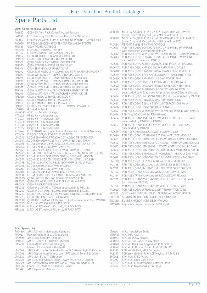
Page 121
Fire Detection Product Catalogue
w w w . s i m p l e x - f i r e . c o m . a u
Spare Parts ListQE90 Comprehensive Spares ListFA1852 QE90 6U Amp Rack Cover Smoked PerspexFA1995 ECP Door only 16U All-in-One Panel E/8/3WIP/ZoneFA2027 FAB,699-237,QE90 ECP+2Z Keypad,3WIP/ZONE - Keypad onlyFA2029 FAB,699-238,QE90 8Z EXTENDER Keypad,3WIP/ZONEFP0539 QE90 PAGING CONSOLEFP0546 FP,F4000 THERMAL PRINTERFP0752 FP,QE90,PRINTER OPTION KIT,699-244FP1067 QE90 4U MODULE BLANK UPGRADE KITFP1068 QE90 FIP/BGA MASTER UPGRADE KITFP1069 QE90 FIP/BGA EXTENDER UPGRADE KITFP1070 QE90 STROBE MASTER UPGRADE KITFP1071 QE90 SPIF MODULE UPGRADE KITFP1072 QE90 ECM MODULE + LOOMS (NO SOFTWARE) UPGRADE KITFP1073 QE90 WIP SLAVE + TERM BOARD UPGRADE KITFP1074 QE90 100W AMP + TRANSFORMER UPGRADE KITFP1075 QE90 2x50W AMP + TRANSFORMER UPGRADE KITFP1076 QE90 2x25W AMP + TRANSFORMER UPGRADE KITFP1077 QE90 4x10W AMP + TRANSFORMER UPGRADE KITFP1078 QE90 4x25W AMP + TRANSFORMER UPGRADE KITFP1079 QE90 200W AMP + TRANSFORMER UPGRADE KITFP1080 QE90 5 MODULE HINGE UPGRADE KITFP1081 QE90 6 MODULE HINGE UPGRADE KITFP1082 QE90 7 MODULE HINGE UPGRADE KITFP1083 QE90 8Z DISPLAY EXTENDER + LOOMS UPGRADE KITFZ9026 4U Module BlankHW0040 003 Lock Tumbler & KeysKT0102 Hinge Kit - 3 Modules 12UKT0103 Hinge Kit - 4 Modules 16UKT0104 Hinge Kit - 5 Modules 20UKT0120 Hinge Kit - 6 Modules 24UKT0105 Hinge Kit - 7 Modules 28UKT0546 Kit, PSU2412 Additional Circuit Breaker incl. Loom & MountingKT0169 KIT,QE90 ECP,ICs FOR RS232/PRINTERLM0043 LOOM,699-090-1,FRC,20W,0.07m,QE90 FIP EXTENDERLM0047 LOOM,699-089,FRC,26W,1.3m,TWISTED,QE90 TRANLM0048 LOOM,699-090-2,FRC,20W,0.25m,QE90 DISPLAY EXTDRLM0060 LOOM,699-087,FRC,34W,1.2m,QE90LM0063 LOOM,699-228,QE90 ECP POWER LOOM,UP TO 21ULM0065 LOOM,1901-174,RS485 Comms BD(also ECM),10 W FRC TO DB9LM0076 LOOM,1922-25,ECM PROG,DB9F to DB9F,NULL MODEMLM0077 LOOM,1922-26,RZDU RS232-ECP HIGH LEVEL LINK,2.9MLM0078 LOOM,1922-27,RZDU RS232-ECM HIGH LEVEL LINK,3MLM0098 LOOM,699-087,FRC,34W,0.8m,QE90LM0100 LOOM,699-087,FRC,34W,1.5m,QE90LM0101 LOOM,699-241,FRC,26W,0.45m + 0.9m,QE90LM0131 LOOM,SERIAL PRINTER CABLE,DB9M to(x)DB9M+DB9FME0200 QE90 CARDFRAME INCLUDING BPLN2000 PCBME0207 QE90 ECP ASSEMBLY 3 WIP PER ZONE incl. PCBME0208 QE90 FLUORESCENT LIGHTME0211 QE90 24V 12A PSU, PSU308 superseded by ME0333ME0212 QE90 24V 3A PSU, PSU2403 superseded by ME0331ME0213 QE90 NOISE CANCELLING MICROPHONE INCLUDING DIN PLUGME0273 QE90 21U Outer Door, Full WindowME0297 QE90 AUTO/MAN/ISOL Keyswitch (incl loom, connector, SW0018)ME0330 MECH ASSY,1966-6,PSU2406,BRICKME0331 MECH ASSY,1966-21,PSU2406,2U RACK MTGME0333 MECH ASSY,1966-22,PSU2412,2U RACK MTG
ME0381 MECH ASSY,QE90 ECP + 2Z KEYBOARD REPLACE,3WIP/Z - (Inner Door with Keypad (for >21U panel) no PCB)ME0382 MECH ASSY,QE90 ECP 8 ZONE KEYBOARD REPLACE,3WIP/Z (Inner Door with Keypad (for >21U panel) no PCB)PA0484 QE90 PCB 1929-1 PAGING CONSOLEPA0623 PCB ASSY,QE90 ECP9702-2 EVAC CNTL PANEL 3WIP/ZONE with socket for site-specific WIP s/wPA0642 PCB ASSY,QE90 WIPS2000 WIP SLAVE,0V REF Replaces PA0622PA0643 PCB ASSY,QE90 ECP9702-2 EVAC CNTL PANEL 3WIP/ZONE incl. WIDGET - see also PA0623PA0646 PCB ASSY,QE90 ALIM9706,AUDIO LINE ISOLATOR MODULEPA0647 PCB ASSY,QE90 AMP200 200W AMPLIFIER MODULEPA0648 PCB ASSY,QE90 TRAN200 200W TRANSFORMER MODULEPA0649 PCB ASSY,QE90 SPIF9709 SECONDARY PANEL INTERFACEPA0650 PCB ASSY,QE90 EAMP9001 4 ZONE POWER AMPPA0651 PCB ASSY,QE90 FIB8910 FIP/BGA MASTER (DIN RAIL)PA0652 PCB ASSY,QE90 FIPE9004 FIP/BGA EXTENSION (DIN RAIL)PA0653 PCB ASSY,QE90 EMSP8911-2 DISPLAY KBD 3WIP/ZN superseded by ME0205 exc. for pre-July 2009 QE90 in 21U cab.PA0654 PCB ASSY,QE90 EMUX9002 MULTIPLEXER superseded by PA0758PA0656 PCB ASSY,QE90 RING9006 MASTER PHONE RINGPA0657 PCB ASSY,QE90 SE9004 SIGNAL INTERFACE (DIN RAIL)PA0660 PCB ASSY,QE90 BPLN2000 BACKPLANEPA0662 PCB ASSY,QE90 WIPS9004 WIP SLAVE use PA0642 with PA0916PA0679 PCB Assy QE90 24V 3A PSU 699-160PA0684 PCB ASSY,TRAN9304-1,4 X 10W MODULE WITHOUT RELAYS superseded by PA0795 or PA0796PA0687 PCB ASSY,TRAN9304-4,2 X 25W MODULE WITH RELAYS superseded by PA0794PA0689 PCB ASSY,QE90,WLED9307,WIP FLASHING LEDPA0690 PCB ASSY,QE90 HAMP9308 2 X 50W AMPLIFIER MODULEPA0691 PCB ASSY,QE90 HTRN9308-1 2X50W TRANSFORMER MODULEPA0692 PCB ASSY,QE90 HTRN9308-2 1X100W TRANSFORMER MODULEPA0695 PCB ASSY,QE90 HTMS9408-1,2*50W XFMR MOD MUSIC SWCHPA0696 PCB ASSY,QE90 HTMS9408-2,100W XFRMR MOD MUSIC SWCHPA0697 PCB ASSY,QE90 STRM9502 STROBE/RELAY MODULE (DIN RAIL)PA0698 PCB ASSY,QE90 ECM9603 EVAC COMMUNICATION MODULEPA0730 PCB ASSY,1922-11-2,24V GENERAL PURPOSE RELAY BDPA0758 PCB ASSY,QE90,EMUX9601,MULTIPLEXER 16SEC SPEECHPA0759 PCB ASSY,QE90,EMUX9601,MULTIPLEXER 60SEC SPEECHPA0792 PCB ASSY,TRAN9705-2,4x25W MODULE C/W RELAYSPA0794 PCB ASSY,TRAN9705-4,2x25W MODULE C/W RELAYSPA0795 PCB ASSY,TRAN9706-1,4x10W MODULE WITHOUT RELAYS (can also use PA0796)PA0796 PCB ASSY,TRAN9706-2,4x10W MODULE C/W RELAYSPA0916 PCB ASSY,QE90 WTRM2000,WIP TERMINATION (DIN)SF0132 SOFTWARE,QE90,EMUX9601,ALERT/EVAC 60SEC SPEECHSU0168 SUNDRY,MICROPHONE,GOOSENECK DM521BSU0169 SUNDRY,MICROPHONE,DESK PM600DSW0018 Keyswitch only-no loom (incl 003 keys)
MX1 Spares ListFA2489 MX1 AS4428.3 Membrane KeyboardFP0913 Replacement MX1 LCD Module KitFP0950 MX1 Loop Card (PA1052) KitFP1002 MX1 16 Zone LED Display ExtenderLB0600 Label,MX1,blank zone label,grey (sheet of 5 supplied with panel)LM0169 MX1 2nd Loop to Controller Loom FRC 10way Style C 400mmLM0291 MX1 Display Interconnect Loom FRC 26way Style B 230mmLM0319 MX1 Main Bd to T-GEN LoomLM0323 MX1 LCD to keyboard Loom 16way FRC Style D 125mmLM0324 MX1 Keyboard to Main Brd Loom 10way FRC Style B 1mLM0339 Loom, FRC, MX1 to 1st Display BoardLT0344 MX1, Operator Manual
LT0360 MX1, Installation GuideME0448 MX1 PSU AssyME0450 MX1 Door c/w HingesME0457 MX1 4U, 80 Zone Display DoorME0464 MX1 4U Door c/w Keypad (no PCB or LCD)ME0465 MX1 4U LCD Door Tested (incl. PCB & FRC)PA1081 PCB assy1982-2, MX1 ControllerPA1057 PCB assy 1982-64 MX1 LCD/Keyboard AS4428.3SF0305 S/w, MX1 CPLD V1.00SF0392 S/w, MX1 Loop Card FlashSF0407 S/w, MX1 FPB Keyboard Controller FlashSF0412 S/w, MX1 Mainboard V1.3x Flash

Page 122
Fire Detection Product Catalogue
w w w . v i g i l a n t -f i r e . c o m . a u
Spare Parts List
4100 Comprehensive Spares List
4100 Front Panel Controls650-127 4100U/ES-S1 replacement LCD, incl. keypad & metalwork566-284 4100U/ES 2 x 40 LCD / keypad PCB, no LCD no metalwork 4100-1277 8 Red & 8 Yellow LED Module4100-1279 Single Blank Display Cover (4100ES)4100-1280 8 Pushbutton 8 Red LED Module4100-1282 8/16 Push Button/ Red-Yellow LEDs4100-1281 8 Pushbutton 8 Yellow LED Module4100-1284 8/16 Push Button/ Red-Green LEDs4100-1287 24 Push Button 24 LED4100-1288 64/64 LED Switch Controller (1st controller per bay)4100-1289 64/64 LED Switch Controller (2nd controller per bay)4100-KT0476 Half Bay Blank Display Cover (4100ES)4100-ME0456 Fan Control Module 4 sets of fan control4100-ME0498 InfoAlarm 8U LCD and hinged door 4100-7155K InfoAlarm LCD on swing down frame kit this is a direct swap in an S1 panel 4100-0640 InfoAlarm memory expansion board required for aftermarket NDU conversions 4100-ME0510K InfoAlarm+ Colour touch screen display on 7U 19inch black door 4100-KT0486 4100U/ES 4U 19 inch rack replacement LCD, incl. keypad and metalwork
Rear Panel PDI (can only be fitted in 4100ES Bay)4100-3107AU IDNET+ Module AU S/W4100-3109AUK IDNet2 250 Point 2-channel IDNET Addressable Loop PDI 4100-3110AUK IDNET2+2 250 Point 4-channel IDNET Address. Loop PDI 4100-3204 4xRelay Card 4xFB Flat Version4100-3206 8x Relay Card Flat Version4100-6070 Fire Panel Internet I/F Module (double size can be mounted in Legacy Bay)4100-0620 4100ES Basic Transponder Interface Card (TIC)4100-6301 Duplex Single Mode Fibre Media left port card4100-6302 Duplex Single Mode Fibre Media right port card4100-6303 Duplex Multi Mode Fibre Media left port card4100-6304 Duplex Multi Mode Fibre Media right port card4100-6077AUK 4100ESi MX loop card (does not require isolators)ME0516 4100ESi MX dual loop card bracketME0504K APS 10A power supply suits 4100ESi BTO systems (not suitable for 15U Compact panels) ME0508K LPS 10A power supply suits 4100ESi 15U Compact panels LM0596K 4100ESi 15U Compact panel battery lead set PA1098K 4100ESi Short PDI back plane spare part 4100-6046V VESDA High Level Interface card PDI
Rear Panel Legacy ME0455 250 Point IDNET Addressable Loop Legacy Mounting4100-MXPK 4100MXP MX Responder on metal bracket (1 slot)4100-0110K MAPNET II Addressable Loop4100-0111 MAPNET II QUAD Isolator4100-0113 RS232 Modem Interface4100-0122 Remote Interface Card (RIC) for Miniplex RTU4100-0154 VESDA HLI4100-9848AU 4100ES XSPS Power Supply (incl. IDNET Addr. Loop)41000157AK 8A Power Supply / Charger (AS4428 approved)4100-ME0470 5A Vigilant PSU / Charger (AS4428 approved)4100-0301 64/64 LED Switch Controller4100-0302 24 Point I/O Module4100-0304 Remote Unit Interface4100-3003K 8XSPDT,3A,24VDC Relay module4100-3024 24 I/O Relay Motherboard + (4100-0302)4100-4321 6 Supervised Relays4100-5004 8 AZF Monitor Zone4100-0451 Panel Mounted Printer8566-719 4100ES CPU Module Spare Part4100-0160K Fire Panel Internet I/F Module
Brigade Interface4100-0199 3U Brigade Kit-ASE Bracket Grey4100-KT0212 3U 2x ASE / V-MODEM Bracket Grey4100-FZ9028 3U WA/Cube ASE Brkt GreyFP0935 4100ES-S1 ASE Door KitFP0937 4100ES-S1 WA/Cube ASE Door KitME0512K 4100ESi Cube ASE & Mic. Brigade Kit (uses 6 slots of a 7U display door) BlackME0513K 4100ESi Centaur II ASE & Mic. Brigade Kit (uses 6 slots of a 7U display door) Black
RTU CabinetsSZ9008 8U RTU Cabinet No PSU (Requires TIC or RIC)SZ9009 8U RTU Cabinet with 2A PSU (Requires TIC or RIC)SZ9005 IOR RTU Cabinet with 2A PSU (Requires TIC or RIC)
Upgrade Kits4100-7149K 19” 4100 to 4100ES U/G kit (new LCD & CPU card )4100-KT0488 Legacy 4100 to 4100ES U/G kit (new LCD & CPU Card)4100-7152K 4100 classic to 4100ES U/G kit for legacy cabinet (complete 4100ES Controller Bay4100-7158K 4100U to 4100ES U/G kit (4100ES CPU)742-516 4100U/ES CPU Motherboard 566-2274100-SX0184 4100ESi InfoAlarm+ mounted on swing down door4100-KT0568 4100-S1 panels replacement trim panel (new trim required to suit larger InfoAlarm+ display)
Options4100-9256 2 unit expansion rack 15U2004100-9257 4 unit expansion rack 28U3104100-9258 6 unit expansion rack 40U3104100-9259 8 unit expansion rack 40U3104100-0401 8 red LED module4100-0402 16 red/yellow LED4100-0403 8/8 Mom. switch/red LEDs4100-0404 8/16Maint. switch/red-grn LEDs4100-0405 8/16 Mom. switch/red-yel LEDs4100-0406 8 yel LED module4100-0420 A/C reset switch module4100-0450 4100 LCD in RTU4100-5129 Ferrite Bead Kit - 3 beads & cable ties4100-9826A 4100 AS4428 upgrade for AS1603 FIPs4100-0410 PA microphone & keyswitch4100-FP1046 8U Expansion Cab, Window, Titania, suits PDI cards only. 1x7U Display Door Fitted4100-FP1086 8U Exp. Cabinet, blank door, Titania, PDI or Legacy cards4100-FP1088 15U Expansion Cabinet, full window door, Titania, 15U Gear Plate, 2x 8 Slot Display Doors4100-FP1087 15U Expansion Cabinet, blank door, Titania, with 10A PSUKT0419 3U Self-Adhesive Document HolderFA2166 Brand Label Domex, SimplexFA2637 4100ESi Outer Door Applique746-177 4100ESi Compact Flash Card
Network Interface 4100-6014AUK Modular Network Card (use on 4100+ to 4100ES does not support NAC Synchronisation)4100-6078 Modular Network Card (Latest NIC for 4100ES/ESI panels supports NAC Synchronisation) 4100-0142K Wired Media Card RS485 (for older leagcy 4100+ Version 3 or earlier network cards) 4100-6056 Wired media card suit 4100+ to ES. Use with 4100-6014 / 6078 network card4100-6057 Fibre Optic Media Card suit 4100+ to ES. Use with 4100-6014 / 6078 network card4100-6072 Fibre Optic Modem left port assembly4100-6073 Fibre Optic Modem right port assembly4100-9840 Mounting brkt for 4100-6063/4 to mount in Legacy bay4100-9863 TCP/IP Physical Bridge, Class B

Page 123
Fire Detection Product Catalogue
w w w . s i m p l e x - f i r e . c o m . a u
This page is intentionally left blank.

Page 124
Fire Detection Product Catalogue
w w w . v i g i l a n t -f i r e . c o m . a u
1. PURPOSETo ensure prompt and consistent handling of warranty returns. The procedure assists in monitoring product quality and continuing to reduce the incidents of defective product.
2. POLICY Johnson Controls offers a product warranty of 24 months from the date of purchase, for Johnson Controls manufactured product. Third party or buy-in items will attract a warranty period as per the manufacturer warranty conditions. Warranty returns will only be accepted for defective material or faulty workmanship. A full credit of the purchase price will be issued for authorised and verified returns of defective product. Johnson Controls will not accept responsibility for consequential, liquidated damages, or third party costs caused as a result of faulty products. Note: Certain products with shorter shelf life may be excluded from the 24 month warranty period. Refer to your Johnson Controls representatives for details.
3. PROCEDURE Product returns - including Third Party Products, e.g. VESDA - will not be accepted unless an RAN (Return Authorisation Number) has been issued to authorise the return. All returned goods must clearly state the RAN on the external packaging.An RAN can be obtained by telephoning Johnson Controls Customer Service on 1300 725 688.When contacting Johnson Controls for an RAN, please have the following information available:
· Your contact details · Location and site details of where the faulty product is installed · Delivery docket or invoice number on which the product was supplied· Item Name· Product Code· Description of fault sufficiently detailed to aid investigation by manufacturer· Serial Number and date code (if applicable) · Details of the likely nature and cause of the fault · Purchase order number and delivery address for the replacement product
Once Johnson Controls approves the return, an RAN will be issued for the return of the product. Customers are required to return the faulty product within one calendar month of the issuing of the RAN. Freight is to be paid by the customer. After one month the RAN will expire and the goods will not be accepted for credit.
4. PROCESSING WARRANTY CREDITS Warranty returns will be credited to the customer only when the failure of the product has been verified by Johnson Controls. It is anticipated that all credits will be finalised within two (2) weeks of product return - in the majority of cases a credit will be processed within one week of the product return. There may be occasions where finalisation will take longer if further technical evaluation or assessment by a third party is required, or other constraints delay processing.
NOTE: In cases where products have been returned under warranty, and after testing and verification, no fault is found, a credit will not be issued. After discussion with customer, the no fault found product/s maybe returned to the customer.
RAN PROCESS
Warranty Procedure
Johnson Controls Customer Service obtain details of fault and complete RAN
register
Customer contacts Johnson Controls Customer Service
YES
NO
Customer identifies faulty product
RAN issued to Customer
START
Customer places purchase order for
replacement product
Replacement product
despatched and invoiced
Faulty product returned by Customer
Store confirms RAN before
accepting goods
Product analysed by:JCI Purchasing
JCI Technical ServicesThird Party assessment
Supplier assessment
Is fault accepted by manufacturer
Credit issued to Customer
STOP
Discuss with customer, return
product if required
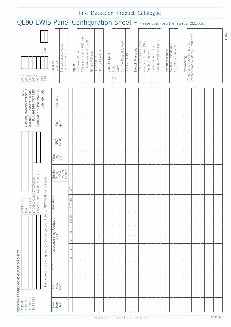
Page 125
Fire Detection Product Catalogue
w w w . s i m p l e x - f i r e . c o m . a u
QE90 EWIS Panel Configuration Sheet - Please download the latest LT0613.xlsx
LT06
13
QE9
0 E
WIS
PA
NEL
CO
NFI
GU
RA
TIO
N S
HEE
TCL
IEN
T:O
RDER
No:
SEC
P(Q
TY)
CON
TACT
:D
ATE:
(FP0
539)
PA
GIN
G C
ON
SOLE
(QTY
)PR
OJE
CT:
LOG
O T
YPE
:(S
U01
68)
GO
OSE
NEC
K M
IC.
(QTY
)D
ATE
REQ
:SP
ECIA
L CA
BIN
ET C
OLO
UR
(SU
0169
) D
ESK
TOP
MIC
.(Q
TY)
CABI
NET
HIN
GIN
G R
EQU
IRED
(PA
0688
) M
IC. P
RE-
AM
P BD
(QTY
)
Cab
inet
s (Q
ty)
18U
21U
Bold
col
umns
are
com
puls
ory
- O
ther
s op
tiona
l. Re
fer
to P
BQ00
94B
for
inst
ruct
ions
28U
40U
Evac
Zo
ne
No
Evac
Zone
Nam
e
Fire
one
Lou
dspe
aker
Out
put
(Wat
ts)
Am
plifi
ers
Stro
be
Out
puts
(Qty
)2A
Per
O
utpu
t
Wip
s(Q
ty0-
3)BG
AIn
puts
Fip
Inpu
tsRe
mar
ksCas
cade
Dis
able
dSt
anda
rd 2
up
1 do
wn
Spec
ial a
ttac
hed
.51
25
LOA
DRA
TIN
GQ
TYIn
puts
BGA
use
FIP
i/ps
BGA
use
3-4
wire
WIP
cct
sBG
A u
se 2
wire
WIP
cct
sFI
P us
e W
IP c
cts
FIP
use
RZD
UFI
P us
e Pa
nelL
ink
Rela
y O
utpu
ts
XFa
ult
Ala
rmA
ny A
lert
/Eva
c/PA
/PA
BXO
ther
att
ache
d
Spee
ch M
essa
ges
Evac
… a
s di
rect
ed (A
us)
Evac
uate
…fir
e ex
it (N
Z)Sp
ecia
l att
ache
dSp
eech
in a
uto
only
Mes
sage
with
Ale
rt t
one
Evac
uati
on t
one
ISO
820
1 (A
us d
efau
lt)A
S 22
20 (N
Z de
faul
t)
Net
wor
king
Att
ach
zone
- z
one
map
ping
, co
ntro
l prio
rity,
inte
r-EC
P W
IPs
etc

Page 126
Fire Detection Product Catalogue
w w w . v i g i l a n t -f i r e . c o m . a u
20-118 Sounder/Strobe, Red 24Vdc 3W 85
2081-9027 Isolated Loop Circuit Protector 54
2190-9156 Monitor ZAM Style B Flush 54
2190-9162 Signal & Control ZAM Style Y Flush 54
2190-9164 Control Relay ZAM DPDT Flush 54
2190-9173 2 Point I/O Module 53
2975-9006 ZAM Box for 2 Pt I/O 57
2975-9260 ZAM Box Cover 102x102x1.8mm 57
4B-DHM DeckHead Mounting 9
40020 External Wall Mount Strobe Only 85
40020B External Wall Mount Strobe incl. Back Box 85
4090-9002 Relay IAM 55
4090-9007 Signal IAM 55
4090-9008 Dual Contact Relay IAM 55
4090-9051 Encapsulated Supervised IAM 57
4090-9101 IDNet Monitor Zone Adapter Mod(ZAM) 55
4090-9116 IDNet Line Isolator 56
4090-9117 IDNet Power Isolator 56
4090-9118 IDNet Relay IAM with T-Sense Input 56
4090-9119 IDNet Relay IAM with Unsupervised Input 56
4090-9120 IDNet 6-point I/O c/w T-Sense & Relay O/P 57
4090-9802 Cover Plate for IDNet Mounting Box 54
4098-9637EA 614T Type A Heat Det 8
4098-9638EA 614T Type B Heat Det 8
4098-9639EA 614T Type C Heat Det 8
4098-9640EA 614T Type D Heat Det 8
4098-9714EA TrueAlarm Photoelectric Smoke Detector 51
4098-9733EA TrueAlarm Heat Detector 51
4098-9754EA TrueAlarm Photo & Heat Multi Sensor 51
4098-9755EA TrueAlarm DSU 52
4098-9789EA TrueAlarm Analogue Addressable Base 52
4098-9793EA TrueAlarm IDNet Isolator Base 52
4098-9794EA TrueAlarm Analogue Addr. Sounder Base 52
4098-9795EA TrueAlarm Multi-sensor Sounder Base 51
4098-9796EA TrueAlarm Analogue Addr. Detector Base 51
4098-9846 TrueAlarm Detector Wire Guard 58
4098-9856 Tube, Duct Sampling 1.2m 52
4099-9701 IDNet Manual Call Point 57
4099-9702 MAPNET II Manual Call Point 57
4100ES Fire Alarm System 42
4100-0110K Addressable Module 53
4100-0154K Simplex/VESDA HLI Panel Mount I/F 48
4100-1026K Mini-Gen Mk2 24V 20W - Simplex 80
4100-3109AUK IDNet2 Loop Card (2 loops) 45
4100-3110AUK IDNet2+2 Loop Card (4 loops) 45
4100-5129 Ferrite Bead Kit - 3 beads & cable ties 122
4100-6069 BACpac™ Ethernet Module 48
4100-FP1045 4100ESi Compact 15U 43
4100-ME0456 4100ES 4x AS1668 Fan Control Module 44
4100-ME0470 4100 5A 24Vdc PSU 91
4100-MXPK 4100MXP MX Responder on Bracket 46
4190-9050 Analogue Monitor ZAM 54
4300 Fire Wire Enclosure 108
4603-9101 Serial LCD Annunciator 47
4906-9103 Wall Mount Multi-Candela Synch. Strobe 84
4906-9104 Ceiling Mount Multi-Candela Synch.Strobe 84
514.001.062 IF800Ex I.S. Interface 105
514.001.063 EXI800 MX I.S. Loop Interface 105
514.001.109 MCP220Ex Collective Call Point 106
514.800.513 CP840Ex MX Addressable Callpoint 105
515.001.025 MCP Glass no logo 10,18
515.001.029 Weather Stopper Flush Mount 11
515.001.030 Weather Stopper Surface Mount 11
515.001.033 Weather Stopper IP036 Break Seal Kit 11
515.001.034 Weather StopperII 11
515.001.035 Weather StopperII Surface Mount 11
515.001.036 Surface Mount Weather Cover 11
515.001.043 Breakglass Keybox 10
515.001.127 Manual Call Point Plastic Insert Element 10
516.016.301 ICAM Air Sampling Detector 100
516.016.303 ICAM Course Filter (Pkt10) 100
516.016.304 ICAM IAS801 1 Pipe Air Sampling Det. 100
516.016.305 ICAM IAS802 2 Pipe Air Sampling Det. 100
516.018.014K VIO800 VESDA Interface Module c/w brkt 25
516.041.003 S271f+ MX Flameproof 103
516.041.004 S271i+ MX Intrinsically Safe 103
516.052.041 MD611Ex Conventional Heat EEx ia IIC T5 106
516.052.051 MD601Ex Conventional Heat EEx ia IIC T5 106
516.054.011.Y MR601TEx Conv. High Perf Opt Smk Det 106
516.061.001 MDU601Ex Enhanced CO & Heat 106
516.600.066 601FEx Conventional Flame Detector 107
516.600.301 VIGILANT 614P Photoelectric Col. Smk Det 7
516.600.304 VIGILANT 614CH CO & Heat Col. Det 7
516.600.305 VIGILANT 614I Ionisation Conv. Smoke Det 7
516.800.006 MX Addressable 801F Flame Detector 17
516.800.066 MX Addressable I.S. 801FEx Flame Det. 107
516.800.530 MX Addressable I.S. 801PHEx Photo/Heat 104
516.800.531 MX Addressable I.S. 801CHEx CO/Heat 104
516.800.532 MX Addressable I.S. 801HEx Heat Det. 104
516.800.911 901SB Low Power Sounder Base 21
516.800.915 Address Flags for 800 Series MX dets 19
516.800.917 M600/M800 Detector Removal Tool 112
516.800.954 SAM800 MX Addressable Sounder Module 24
516.800.956 SAB801 MX Addressable LED Beacon 24
516.800.957 LPSB3000 Sounder Base 21
516.800.958 LPAV3000 Sounder/Beacon 21
516.800.959 DAB3-4 Mounting Flange 21
516.850.051.E 850PH Gen6 MX Photoelectric/Heat Det. 16
516.850.052.E 850P Gen6 MX Photoelectric Detector 16
516.850.053.E 850H Gen6 MX Heat Detector 16
517.001.184 S100/200 Flame Det Mnt Brkt S/S 102,113
517.001.224 SOLO704 Adaptor Tube 112
517.001.226 SOLO101 Extension Tube 112
517.001.230 SOLO100 Telescopic Pole 112
517.001.240 X200 SOLO200 Detector Changer 112
517.001.277 SOLO461 Heat Detector Tester Head Unit 112
517.001.255 X330 SOLO330 Aerosol Dispenser 112
517.001.259 Galvanic Current Repeater 1 Channel 105
517.001.262 CO Test Gas 120g can 112
517.001.263 S200 Weather Protection Assy 112
517.001.264 SOLO610 Carry Bag 110
517.001.266 S200+ Spares Kit & Sealant 102
517.001.273 SOLO770 Spare Battery Baton 112
517.001.279 SOLO A10s Test Smoke 250ml can 112
517.035.007 M520 Cover Ancillary Cover 26
517.035.010 K2142 PC/ABS Double Gang Back Box 26
517.035.011 K2214 Aluminium Double Gang Back Box 26
517.035.015 QFB/2 PC/ABS Double Gang Back Box 26
517.050.015 Volume Adjustment Tool 26
517.050.023 5BEx Universal Base for 600/800 Ex Det. 107
517.050.041 4B Universal Base 9,20
517.050.042 4B - C Continuity Base (MX1 only) 20
517.050.043 4B - I Isolator Base 20
517.050.051 4B-DHM DeckHead Mount 9,21
517.050.056 Ceiling Tile Adaptor Back Box 9,21
517.050.057 Ceiling Tile Adaptor Bezel and Clamp 9,21
517.050.058 Ceiling Tile Adaptor Plate 9,21
517.050.060 Ceiling Tile Adaptor Kit 9,21
517.050.612 Terminal Accessory Kit 9
545.800.004 LIM800 MX Addressable Loop Isolator Mod. 23
547.004.002 DIN Rail Mounting Bracket 26
555.800.063 SIO800 MX Single Input/Output Module 25
555.800.070 QMO850 MX Quad Monitored O/P Module 24
555.800.071 QIO850 MX Quad Input/Output Module 24
555.800.073 QRM850 MX Quad Relay Output Module 24
555.800.065 MIO800 MX Addressable Multi-I/O Module 23
557.001.040 MkII Sounder Base Terminal Cap 9,21,24
557.201.303 MIO DIN-Rail Mounting Kit 26
557.201.401 D800 MX Module Ancillary Housing 26
557.201.410 MX Quad I/O Module IP66 Anc. Housing 26
576.501.047 Beacon/Sounder Mounting Bracket 85
576.501.060 IP45 Multi-Tone Sounder 85
576.501.062 IP66 Multi-Tone Sounder 85
576.501.224 Comb. Sounder/Strobe Shallow Base 85
576.501.227 Comb. Sounder/Strobe Deep Base 85
577.001.035 601SB Sounder Base 9
577.800.006 DDM800 MX Universal Fire & Gas Det. Mod 22
592.001.005 T110 Adaptor For S131/161 113
592.001.010 T110/T210 PP9 Battery and Charger Kit 113
592.001.012 T110 Test Src SOLO704/100/101 103,105,113
592.001.014 T210+ Adaptor for S200+ Detectors 113
592.001.016 T210+ Plus Test Source for S200+ only.
Suitable For Use In Hazardous Areas 113
592.001.018 T110 Adapter for 601/801F Detect’s 105,107
592.001.019 T210+ Adaptor for FV300/FV400 113
601SB MkII Sounder Base 9
733-794 4100 Download Port Cable 10W FRC-DB9 66
802SB Low Power Sounder Base 21
814RB MX Addressable Relay Base 21
850EMTK MX Engineering Management Tool Kit 19
885WP-B Type B Conventional Thermal Det. Potted 8
A2339 Audio Line Attenuator 100V 100W 88
A2255 Audio Line Attenuator 100V 40W 88
A2260 Audio Line Attenuator 100V 10W 88
AAM2 Alarm Acknowledge Module FP0894/5 60
ADC130-Mk2 130 series Control Module 40
ADM130-Mk2 130 series Monitor Module 40
ADM131-Mk2 130 series Mini Monitor Module 41
ADS130-Mk2 130 series Short Circuit Isolator 40
B200SR 130 Series Sounder Base 39
B501AUS 130 Series Detector Base 39
BELL01 Motorised Bell 200mm 24Vdc 89
BELL002 Bell Back Box 89
C0612D QE90 WIP Phone External Speaker 76
C2052 Horn Speaker Mount ‘Wurli-Gig’ 87
CCU CCUNet 72
CG0002-CLIENT XLG-C/S Client/Server Software & Dongle 37
CG0002-CS XLG-C/S Client Only Software 37
CIM800 MX Addressable Contact Input Module 22CL0423 F3200 Transformer 240V 2.5A 31V RMS 120
CP820 MX Addressable Manual Call Point 18
CP830 MX Addressable IP67 Manual Call Point 18
CRC-TEST Detector Test Smoke 71g 112
D515B Duct Housing c/w 5B base 8
D51COVER D51 Cover 8
D51L D51 Baffle pkt of 10 8
D51F D51 Filter pkt of 10 8
D51K100 D51 Sampling Tube End Cap pkt of 10 8
D51T3 D51 Sampling Tube 3m 8
D51 Duct Housing without base 8
D51MX MX Duct Housing 17
D51Z131 130 Series Duct Housing 39
DD0084 QE90 FIP EOL Diode Zener 10V 1W 5% 79
DIM800 MX Addressable Detector Input Module 22
DLE201215A Strobe Amber - IP65 84
DLE201215R Strobe Red - IP65 84
E502 Remote Indicator 75mm dia Fire Alarm 59
E521 Rem. Ind. 75mm dia F A in Conc. Space 59
E523 Rem. Ind. 75mm dia Fire Alarm in Room 59
E524 Rem. Ind. 75mm dia Fire Alarm Above 59
E525 Rem. Ind. 75mm dia Fire Alarm in Duct 59
E526 Rem. Ind. 75mm dia Fire Alarm in Roof 59
E529 Rem. Ind. 75mm dia Fire Alarm in Cupboard 59
E542 Rem. Ind. Rect. Fire Alarm 59
E551 Rem. Ind. Rect. F A in Concealed Space 59
E553 Rem. Ind. Rectangular Fire Alarm in Room 59
E554 Rem. Ind. Rectangular Fire Detector Above 59
E555 Rem. Ind. Rectangular Fire Alarm in Duct 59
E556 Rem. Ind. Rectangular Fire Alarm in Roof 59
E561 Rem. Ind. Rect. latch.F A in Conc. Space 59,107
E566 Rem. Ind. Rect. latch.F A in Roof Space 59,107
E573 Rem. Ind. Rect. latch Fire Alarm in Room
59,107E574 Rem. Ind. Rect. latch Fire Alarm Above 59,107
E575 Rem. Ind. Rect. latch Fire Alarm in Duct 59,107
E700-CSC Capillary Sampling Connector 101
E700-CT Capillary Sampling Tube 8mm OD 101
E700-EC End Cap - not drilled 101
E700-FILFOAM Filter elements for E700-FILASSY 101
E700-FMK-2 Filter for VESDA Mk2 System 99
E700-HASP Heat Activated Sampling Point 101
E700-HASP-KIT Heat Activated Sampling Point Kit 101
E700-J J - Fitting, 2 Branch Adaptor 101
E700-LB Long Radius Bend 150mm 101
E700-P VESDA Bell End Pipe 4m x 10 lengths 101
E700-PC Pipe Clip - Single Point Fix 101
E700-PJ Pipe Junction Fitting 101
E700-SB Small Radius Bend 90mm 101
E700-SP Sampling Point - Mini 101
E700-SPDCL Sampling Point Decal 200 per roll 101
E700-SPLR VESDA LBL Sampling Point Label 101
E700-SRB Standard Base for HASP 101
E700-T Solid Tee 101
E700-TA Trunk Adaptor 101
EA0005 OneShot 5W, 100mm Spkr/grille incl. cap. 87
EA0006 100mm Speaker incl tx & cap. 87
EA0007 200mm Speaker incl tx & cap. 87
EA0008 200mm Speaker Surf. Mnt. incl tx & cap. 87
IndexStockcode Product Description Page Stockcode Product Description Page Stockcode Product Description Page

Page 127
Fire Detection Product Catalogue
w w w . s i m p l e x - f i r e . c o m . a u
EA0009 OneShot 5W 200mm Spkr & grille incl.cap.88
EA0013 ABS 10W Horn Spkr + cap. 255mm 86
EA0016 ABS 20W Horn Spkr + cap. 285mm 86
EA0017 Alum 30W Horn Spkr 270mm 86
EA0020 8 Ohm 10W ABS Horn Speaker 87,90
EA0025 OneShot Spkr 5W 100mm AS7240.24 88
EA0027 OneShot Horn Spkr 10W AS7240.24 Wht 87
EA0028 OneShot Horn Spkr 10W AS7240.24 Blk 87
EA0029 Surf Mnt Spkr 5W AS 7240.24 - White 88
EA0030 Surf Mnt Spkr 5W AS 7240.24 - Black 88
EA0031 Surf Mnt Spkr 5W 200mm AS7240.24-Wht 88
EA0032 Surf Mnt Spkr 5W 200mm AS7240.24-Blk 88
EA0033 Surf Mnt Spkr 15W 200mm AS7240.24-Wht 88
EA0035 OneShot Ceiling Tile Support Split Ring 87
EA0035 OneShot Ceiling Tile Support Pan 87
EA0036 OneShot Spkr 5W 100mm AS7240.24-Wht 88
EA0037 OneShot Spkr 5W 100mm AS7240.24-Blk 88
EA0101 Grille for EA0007 87
EA0102 Grille for EA0006 87
EA0104 Screw Covers Pkt of 80 87
EA0301 Strobe Amber Ax35 84
EA0302 Strobe Red Ax35 84
EA0305 Strobe Amber TK86HP24 84
EA0306 Strobe Red TK86HP24 84
EA0313 Dual Strobe Unit 85
EA0031 Surf Mnt Spkr 5W AS 7240.24 - White 88
EA0032 Surf Mnt Spkr 5W AS 7240.24 - Black 88
EA0332 Strobe IP65 LED Yellow Flashing 84
EA0335 Strobe IP65 LED Red Flashing 84
EA0405 Magnetic Door Holder Release Switch 93
EA0407 Electro-magnetic Door Holder 150mm 93
EA0408 Electro-magnetic Door Holder 300mm 94
EA0409 Floor Mount Door Holder & Box 94
EA0410 Electro-mag Door Hold 150mm,90deg 94
EA0411 Electro-mag Door Hold 300mm,90deg 94
EA0412 WIP Phone Surface Mount Enclosure 76
EA0413 Electro-mag Door Hold 450mm,90deg 94
EA0414 Electro-mag Door Hold 385mm 94
ESS7010ISA EExia LED Warning Light - Amber 85
ESS7010ISR EExia LED Warning Light - Red 85
ESS7010R Xenon Strobe 84
ESS7111XR IP Rated Flashing Beacon 85
F3200 Conventional Intelligent FIP 5
F3200 8Z F3200 8 Zone FIP 5
FA1185 F4000 Gear Plate Standard 62
FA1199 F4k Gear Plate Large Sided 1200x483x180 62
FA1218 F3200 15U Outer Door Perspex 62
FA1227 Blanking Plate 9.5U 1931-24 62
FA1228 F3200 15U Outer Door Blank 62
FA1235 Flush Surround for 15U Cabinet 62
FA1267 F3200 Gear Plate Standard 480x460 62
FA1299 Flush Surround for 8U Cabinet 62
FA1366 F4k Gear Plate Large Sideless 1200x483 62
FA1833 QE90 Gear Plate suit ≥28U cabinet 62
FA1846 QE90 Gear Plate suit ≥18U cabinet 64
FA1852 QE90 6U Smoked Perspex Panel 62
FA1922 QE90 Paging Console Keypad 75
FA1983 F4k Gear Plate 18U Sideless 770x483 62
FA1929 Flush Surround for 18U Cabinet 62
FA1930 Flush Surround for 28U Cabinet 62
FA1931 Flush Surround for 40U Cabinet 62
FA1984 F4k Gear Plate 18U Sided 770x482x180 62
FA2017 QE90 5.5U Blanking Plate 14,62
FA2019 QE90 Bracket SECP Battery 62
FA2027 Keypad Only, ECP+2Z Keyboard,3 W/Z 78
FA2029 Keypad Only, 8Z Extender Keyboard,3 W/Z 78
FA2031 Flush Surround for 21U Cabinet 62
FA2040 F4k Gear Plate Basic 15U 540x460 62
FA2113 40U Outer Door Full Window 62
FA2150 AS4428 4U Membrane Overlay 18,120
FA2317 AAM2 Cover ‘Press to ACK Fire Alarm’ 60
FA2318 AAM2 Cover ‘Press to ACK Alarm Cancel’ 60
FA2776 AVI Face ‘Extinguishing Syst. Inoperative’ 90
FA2700 AVI Faceplate ‘Fire Alarm Evac Area’ 90
FA2701 AVI Faceplt ‘Fire Alarm Do Not Enter’ 90
FA2702 AVI Face ‘Do Not Enter CO2 Dischgd’ 90
FA2703 AVI Face ‘D N E FM200 Discharged’ 90
FA2704 AVI Face ‘D N E Inergen Discharged’ 90
FA2710 AVI Face ‘Warning Fire Door Closing’ 90
FP0101 Electromagnetic Door Holder 93
FP0475 F4000 Display Ext. Kit 1901-26 5,14,61
FP0487 Loop Booster Unit 14, 29
FP0507-5 EOL002B Pulsing EOL (pkt 5) 14,27
FP0529 Empty ADR/MPR box 14,26
FP0539 Paging Console 75
FP0545 Printer Option Kit 1901-112 14
FP0546 Printer DPU411 14
FP0553 F3200 8 Zone Expansion Kit 6
FP0554 F3200 8 Relay Expansion Kit 6
FP0556 F3200 15U Empty Cabinet Full Window 62
FP0557 F3200 15U Empty Cabinet Blank Door 62
FP0570 Local Gas Control Station - Auto 70
FP0572 Local Gas Control Station - Manual 70
FP0575 F4000 MPR 1901-141 14,27
FP0576 PSU/Battery Box 440x550x211mm 62
FP0584 F3200 8U Empty Cabinet Full Window 62
FP0586 Protocol Translation Module 1942-1 14,33
FP0749 F3200 PSU Upgrade Kit 3A to 6A AS1603 6
FP0755 F4000 ADR-M 4mA 1901-116 14,27
FP0766 PSU1948 24V 2A 92
FP0770 MX4428/F3200 NDU to Ring Netwk Kit 31,34
FP0771 I-HUB Networking Kit 14,31,34
FP0779 F3200 PSU Upgrade Kit 3A to 6A AS4428 6
FP0780 F3200 24 Zone, 3A PSU, No Cardframe,15U 5
FP0781 F3200 64 Zone, 3A PSU, incl. Cardframe,15U 5
FP0782 F3200 24 Zone, 6A PSU, No Cardframe,15U 5
FP0783 F3200 64 Zone, 6A PSU, incl Cardframe,15U 5
FP0784 F3200 8 Zone, 3A PSU, 8U 5
FP0787 RDU Slimline Wall Mount 71
FP0788 RDU Slimline Flush Mount 71
FP0789 RDU 4U 19” Rack 71
FP0790 NDU 15U MAF, PSU 71
FP0791 NDU Slimline Surface Mount 71
FP0792 NDU Slimline Flush Mount 71
FP0793 NDU Slimline Deep c/w I-HUB 71
FP0794 NDU 4U 19” Rack 71
FP0795 F3200 Network Upgrade Kit (AS 4428) 5
FP0802 PSU1948 12V 0.5A for ASE 92
FP0804 24V 0.5A PSU 91
FP0821 MX4428 master, LCD, 5A, 15U, no LEDs 14
FP0824 MXP Responder in box 14,27
FP0827 Standard Network Kit 14
FP0837 MIM801 23
FP0842 Alarm Acknowledge Module AAM4 60
FP0852 24V 2A VESDA PSU 92
FP0853 AVI MkII 2 Line Red 92
FP0854 AVI MkII 3 Line Yellow 92
FP0865 Compact FF Surface Mount 71
FP0866 Compact FF Flush Mount 71
FP0871 MX4428 Single Loop Panel incl. ASE brkt 14
FP0872 MX4428 Single Loop Panel incl. Cube brkt 14
FP0876 F3200 AS4428 8U, 3A PSU 1U Gas Ctrl. 6
FP0877 F3200 AS4428 15U, 6A PSU 1U Gas Ctrl 6
FP0880 Nurse Station Annunciator Flush Mnt 71
FP0881 Nurse Station Annunciator Surface Mnt 71
FP0882K PSU F4000 AS1603 24Vdc 5A 90,118
FP0894 AAM2 with FA2317 Fascia 60
FP0895 AAM2 with FA2318 Fascia 60
FP0898 MX Loop Tester 18
FP0902 PC Paging Console 75
FP0927 MX1 15U 3U ASE bracket 12
FP0928 MX1 15U 3U WA/Cube ASE bracket 12
FP0935 4100ES-S1 ASE Door Kit 44,62
FP0937 4100ES-S1 WA/Cube ASE Door kit 44,62
FP0938 WIP Phone 76
FP0948 MX1 15U 3U Blank 12
FP0949 MX1 15U Base Panel 12
FP0950 MX1 Loop Card Kit 12
FP0986 PIB Panel-Link Internet Protocol Bridge 32
FP0991 MX1 Remote Fire Brigade Panel 12
FP0996 MX1 4U Remote Fire Brigade Panel 12
FP1002 MX1 16Z LED Display Extender 12,61
FP1023 4-Zone Paging Kit for T-GEN BOWS 83
FP1024 4-Zone Emerg. Paging Kit for T-GEN BOWS 83
FP1027 MX1 Loop Card/MX Module Mtng Bracket 26
FP1030 MX1 15U Empty Wndw Cab, no MCP, Titania 12,62
FP1032 OSD139 Fibre Optic Modem x2 Mntg Kit 31,34
FP1037 AVI-Mk2 IP65 24V 2-Line Red no Fascia 90
FP1038 AVI-Mk2 IP65 24V 3-Line Yel no Fascia 90
FP1040 MX1 8U Panel Aust 3U Blank Fitted 12
FP1056 MX1 3U 12-Way AS1668 Ctrl Door 2 Ctrls 69
FP1057 MX1 2-Way AS1668 Ctrl Bd Extension Kit 69
FP1062 MX1 4xModule Bracket 14,26
FP1063 MX1 4xDDM800 Bracket 14,26
FP1083 QE90 8Z Display Ext. 3W/Z inc PCB 78
FP1084 MX1 15U Empty Cab, Titania 69
FP1092 6U NT Brigade Door Kit Vigilant grey 62
FP1093 6U NT Brigade Door Kit Simplex black 62
FP1135 Isolation Amplifier T-Gen2 60W 89
FP1143 T-Gen2 High Level Interface Module 89
FW105 105°C Sensor Cable 108
FW180 180°C Sensor Cable 108
FW68 68°C Sensor Cable 108
FZ3031 16 Zone LED Display PCB (LHS) 14,61
FZ9002 7U Blank Hinged Inner Door 5,14,62
FZ9003 6U Blank Panel Acrylic 5,14,62
FZ9004 4U Blank Panel 5,14,62
FZ9005 3U Blank Panel 5,14,62
FZ9006 2U Blank Panel 5,14,62
FZ9007 1U Blank Panel 5,14,64
FZ9011 7U Door 5 AS1668 Fan Controls 69
FZ9012 7U Door 15 AS1668 Fan Controls 69
FZ9015 5U Blank Panel 5,14,62
FZ9016 6U Blank Panel 5,14,62
FZ9028 3U WA/Cube ASE Bracket & Loom 5,14,62
FZ9036 2U Door 5 AS1668 Fan Controls 69
FZ9037 7U Blank Panel with Front Doc. Holder 62
GX93R Mini Horn Sounder ISO 8201 T3 Red 87
GX93W Mini Horn Sounder ISO 8201 T3 White 87
HP-20EEXIIN(T) 20W Ex Horn Speaker 86
HW0040 Lock A/CR16/01/3B/N04 003 Key 62,120
HW0202 Block, Hinge Set 6mm 62
HW0226 Key only 003 style 62
IC0320 F4k IC 28C64 8k EPROM 120
IC0382 F4k IC 128k CMOS RAM (U3 PA0482) 120
IC0414 F4k IC 28C010 128k EEPROM (U2 PA0482) 120
K2142 Back Box for MX modules 24
KFD0-Ex151 Galvanic Current Repeater 1 Channel 108
KFD0-Ex251 Galvanic Current Repeater 2 Channel 108
KFD2-STC4-Ex1 Galvanic Current Repeater 1 Ch SMART 108
KT0072 F3200 Cardframe Upgrade Kit 6
KT0113 Kit, AS1668 Control Module Type 3 69
KT0144 Kit, PMB RS485 Module 31,34
KT0178 F4000 Point Text Upgrade Kit 120
KT0199 3U ASE Bracket 5,14,62
KT0274 Kit,F3200 AS 1603 to AS 4428 Upgrade 5,120
KT0292 AVI Expansion Kit Red LED PCB+hardware 90
KT0293 AVI Expansion Kit Red Double Sided 90
KT0419 3U Self-Adhesive A4 Document Holder 5,14,62
KT0478 AS1668 5-Way Fan Control Module Kit 69
KT0512 AS1668 4-Way Fan Control + Com.Master 69
KT0519 QE90 AMP200 Kit incl. 2xPCB, 1x Loom 77
KT0546 PSU2412 Additional Circuit Breaker Kit 91
LIM800 MX Line Isolator Module 23
LM0041 Programming Cable DB9 to CIE 14,66
LM0042 Programming Cable DB25 to CIE 66
LM0047 QE90 TRAN8872 26W FRC Style D 66
LM0049 26W FRC Style B 0.25m 61,66
LM0053 20W FRC Style A 0.3m F3k 8 Rly to 8Z 66
LM0056 20W FRC Style B 1.4m 61
LM0065 RS485 DB9 to 10W FRC 31,66
LM0073 20W FRC Keybd to Main bd 1.45m 66,120
LM0076 ECM Programming DB9F to DB9F 31,34,66,71
LM0083 20W FRC Keybd to Main bd 0.7m 66
LM0084 10W FRC Style B 0.35m 66
LM0091 10W FRC Style C 0.5m 66
LM0092 F3200 Mk2 Controller to 1st Display 61,66
LM0118 26W FRC Style B 0.6m F3k MAF to Cntrlr 68
LM0141 4W QE90 AMP200 Interconnect Loom 77
LM0151 10W FRC to 12W Molex MX4428 RingNet 31
LM0152 10W FRC ECM/F3200 Net X-Over 0.7m 31
LM0160 10W FRC Style C 1.0m 31
LM0185 MX4428 Molex to CMOS/RS-232 66
LM0195 MAPNET Power Harness 66
LM0291 26W FRC Style B 0.23m MX1 Disp Intercon. 61
LM0295 26W FRC Style B 0.7m 61
LM0339 26W FRC 0.2m Keybd-1st Display 61,66
IndexStockcode Product Description Page Stockcode Product Description Page Stockcode Product Description Page

Page 128
Fire Detection Product Catalogue
w w w . v i g i l a n t -f i r e . c o m . a u
IndexStockcode Product Description Page Stockcode Product Description Page Stockcode Product Description Page
LM0572 Loom, I-HUB - OSD139 Mdm 1901-303 31,34
LPS800 MX Loop Powered Sounder Module & Cover 25
M520 MX Module Cover 26
MD601EX Conventional I.S. Heat Detector 106
MD611Ex Conventional I.S. Fixed Temp Heat Det. 106
MDU601EX Conventional I.S. CO & Heat Det. 106
ME0060 7U LED Display Door 61
ME0088 IOR Empty Cabinet 449x494x82mm 28,62
ME0098 4U F3200 AS4428 Door & Ctrlr PCB 5,120
ME0200 QE90 Cardframe incl. BPLN2000 76,10
ME0207 QE90 ECP Panel 3W/Z incl. PCB 78
ME0213 Mic.Dynamic, QE90 ECP9002 - DIN plug 75
ME0250 Cabinet Empty IP66 20U x 200 62
ME0251 Cabinet Empty 21U x 310 Window 62
ME0252 Cabinet Empty 18U x 135 Window 62
ME0253 Cabinet Empty 18U x 310 Window 62
ME0254 Cabinet Empty 28U x 135 Window 62
ME0255 Cabinet Empty 28U x 310 Window 62
ME0256 Cabinet Empty 40U x 135 Window 62
ME0257 Cabinet Empty 40U x 310 Window 62
ME0258 1U Document Tray (135 deep) 14,62
ME0259 1U Document Tray (310 deep) 14,62
ME0260 Cabinet Empty IP65 20U x 310 304 S/S 62
ME0261 Cabinet Empty 21U x 310 Blank Door 62
ME0262 Cabinet Empty 18U x 135 Blank Door 62
ME0263 Cabinet Empty 18U x 310 Blank Door 62
ME0264 Cabinet Empty 28U x 135 Blank Door 62
ME0265 Cabinet Empty 28U x 310 Blank Door 62
ME0266 Cabinet Empty 40U x 135 Blank Door 62
ME0267 Cabinet Empty 40U x 310 Blank Door 62
ME0268 Cabinet Empty 21U x 310 Window 62
ME0269 Cabinet Empty 21U x 310 Blank Door 62
ME0270 Cabinet Empty IP65 30U x 310 62
ME0273 Cabinet Door 21U Outer Full Window 62
ME0274 Cabinet Door 28U Outer Full Window 62
ME0276S Cabinet Door 40U Outer Full Window 62
ME0280 Cabinet Empty IP65 40U x 310 62
ME0286 Cabinet Door 40U Outer Blank 62
ME0290 Dynamic Mic. for T-GEN 50/QE90/ECP9702 75
ME0292 T-GEN 50 Empty Box Keyed 003 82
ME0297 QE90/TGEN 50 A/I/E Sw incl loom & con 85
ME0330 PSU2406 24V 6A Brick for QE90 91
ME0331 PSU2406 24V 6A 2U mounting 91
ME0333 PSU2412 24V 12A 2U mount for QE90 91
ME0334 PSU2406F 24V 6A Brick F4000 91
ME0336 Cabinet Door 15U Outer Full Window 62
ME0340 PSU2406 24V 6A 2U mounting F4000 91
ME0341 Cabinet Empty IP65 20U x 310 62
ME0343 PSU2412F 24V 12A 2U mount F4000 91
ME0355 4U Door, AS4428 keypad, PA0890 PCB 120
ME0420 AAM2 Alarm Acknowledge Module 61
ME0439 2 Zone Gas Flood 7U Door & Loom 70
ME0440 3 Zone Gas Flood 7U Door & Loom 70
ME0441 4 Zone Gas Flood 7U Door & Loom 70
ME0442 1 Zone Gas Flood 1U Door & Loom 70
ME0444 4U Door & AS4428 Keypad (no PCB) 120
ME0457 4U Door 5 x Zone Display (door only) 12,14,61
ME0476 MX4428 24Vdc 5A PSU 92
ME0512K 4100ESi Cube ASE & Mic kit 62
ME0513K 4100ESi Centaur11 ASE & Mic kit 62
MIM800 MX Addressable Mini Input Module 23
MIM801 MX Addressable Mini Input Module (N/C) 23
MIO800 MX Multi Input/Output Module 23
MR601TEx Conv. Optical Smoke Detector ATEX app 106
MX1 Analogue Addressable FIP 12
MX4428 Analogue Addressable FIP 14
MX4428SL Analogue Addressable FIP 1 Zone 14
NT0030 Nut Cage M6 ZP 62
OSD139HS Fibre optic HS Multimode RS232 Modem 31
OSD139HSL Fibre optic HS Single mode RS232 Modem 31
OSE-SP OSID Emitter (std power, Battery) 109
OSE-SPW OSID Emitter (std power 24V) 109
OSE-HPW OSID Emitter (high power 24V) 109
OSE-RBA OSID Emitter Replacement Battery Pack 109
OSI-10 OSID Imager 7 deg) 109
OSI-90 OSID Imager (90deg) 109
OSI-LS OSID Light Shield 109
OSID-EHE OSID Emitter Environmental Housing 109
OSID-EHI OSID Imager Environmental Housing 109
OSID-INST OSID Install Kit (align’t. tool, PC cbl, etc.) 109
P131A-Mk2 130 Series Photoelectric smoke detector 38
PA0449 F4000 Power Supply PCB 1901-2 120
PA0453 Relay Responder Module 1901-15 14,27
PA0454 16-Zone Display Board 61
PA0463 F4000 Loop Booster PCB 1901-35 29,120
PA0470 16-Way Relay PCB 29
PA0473 IOR PCB 32 in/32 out 1901-72 14, 29
PA0474 32-Way Input Termination PCB 29
PA0475 IO-NET 32 Way Input PCB 29
PA0481 RZDU to RS232 I/F PCB 1901-100 29,78,120
PA0482 F4000 Memory/LCD I/F PCB 1901-102 120
PA0483 IOR Unprotected Terminal PCB 29
PA0484 QE90 Paging Console PCB 1929-1 18
PA0487 Banked EPROM Emulator PCB 1901-113 120
PA0491 F3200 MAF/PSU 3A 5
PA0494 Bell Monitor Board 89
PA0498 IO-NET 16-Way Output PCB 29
PA0640 TPI PCB only 62
PA0642 QE90 WIP Slave 0V ref WIPS2000 PCB 79
PA0643 QE90 ECP7902-2 3WIP/Z PCB 79
PA0644 QE90 VIF0907 VoIP I/F PCB 78
PA0646 QE90 Audio Line Isol ALIM9706 PCB 79
PA0647 QE90 200W Amp Module AMP200 79
PA0648 QE90 200W Transformer TRAN200 PCB 79
PA0649 QE90 SEC panel I/F SPIF9709 PCB 78
PA0650 QE90 4 Zone Pwr Amp EAMP9001 PCB 77
PA0651 QE90 FIP/BGA Master FIB8910 PCB 77
PA0652 QE90 FIP/BGA Ext FIPE9004 PCB 79
PA0653 QE90 Disp/Kybd 3WIP/Z EMSP8911-2 79
PA0657 QE90 Signal I/F SE9004 PCB 78
PA0660 QE90 Backplane BPLN2000 121
PA0688 QE90 Mic. Preamp. 1923-19 PCB 77
PA0689 QE90 WIP Flashing LED WLED9307 PCB 77
PA0690 QE90 2x50W Amp HAMP9308 PCB 77
PA0691 QE90 2x50W Txfrmr HTRN9308-1 PCB 77
PA0692 QE90 1x100W Txfrmr HTRN9308-1 PCB 77
PA0695 QE90 2x50W Music Txfrmr HTMS9408-2 79
PA0696 QE90 1x100W Music Txfrmr HTMS9408-2 77
PA0697 QE90 Strobe/Relay STRM9502 PCB 79
PA0698 QE90 Comm Module ECM9603 PCB 80
PA0700 IO-NET Programmer PCB 29,30
PA0711 RS485 Comms PCB Plug-on 1901-139-1 31,120
PA0712 RS485 Comms to RS232 PCB 31
PA0713 MPR PCB 1901-141 14, 27
PA0730 PCB General Purpose Relay 24V 61
PA0758 QE90 Mux. 16s EMUX9601 PCB 80
PA0759 QE90 Mux. 60s EMUX9601 PCB 80
PA0766 T-GEN 50 PCB, ISO 8201, Aust speech 80
PA0769 16W Unprotected Term Bd c/w resistors 29
PA0773 RS485 Comms PCB FRC 1901-139-3 34,120
PA0790 16-Way Clean Contact Input Board 62
PA0792 QE90 4x25W TRAN9705-2 PCB 78
PA0794 QE90 2x25W TRAN9705-4 PCB 78
PA0795 QE90 4x10W Amp TRAN9706-1 PCB 78
PA0796 QE90 4x10W TRAN9706-2 PCB 78
PA0799 PCB PTM no software 1931-84-3 33,120
PA0804 PCB F3200 AS1603 Ctrl no s/w 120
PA0815 ADR-M 4mA 15V MCP 1901-116 14
PA0838 ZAU401 Zone Adaptor Unit 58,107
PA0839 PCB Panel-Link I-HUB ECM9603 31,34
PA0868 PCB CMOS/TTL RS232 I/F 1931-110 31,34
PA0873 F3200 MAF/PSU 3A - AS 4428 6
PA0874 F3200 MAF/PSU 6A - AS 4428 6
PA0878 PCB CMOS/TTL Signal Splitter 31,34
PA0880 PCB DB25 to 10-way FRC Adaptor 34
PA0890 F4000 PCB AS4428 keypad/LCD module 120
PA0891 F4000 PCB AS1603 keypad/LCD module 120
PA0893 MX4428 MXP Responder PCB only 14
PA0909 PCB F3200 4428 Ctrl no s/w 1931-111-1 18
PA0915 PCB Fused Power Distribution 60
PA0916 QE90 WIP Termination WTRM2000 PCB 79
PA0951 PCB MX4428 Main Bd no s/w 1901-12 18
PA1026 Mini-Gen Mk2 24V 80
PA1038 MXP Loop Filter PCB 18
PA1040S MX4428 Mainboard incl. Mem-LCD I/F 120
PA1043 ISO 8201 Strobe Driver Module PCB 84
PA1081 MX1 Controller Board 120
PA1144 QE90 WIP Slave 0V ref WIPS2017 PCB 79
PS12120 Battery 12V 12Ah 91
PS12180 Battery 12V 17Ah 91
PS12240 Battery 12V 24Ah 91
PS12400 Battery 12V 40Ah 91
PS12650 Battery 12V 70Ah 91
PS1270 Battery 12V 7Ah 91
QE90 EWIS Controller 74
RACO232 Steel Box for IDNet Devices 54
RIM800 MX Addressable Relay Input Module 24
S271f+ MX Addressable Triple IR Flame Det Exd 103
S271i+ MX Addressable Triple IR Flame Det Ex ia 103
SAB801 MX Sounder Addressable LED Beacon 24
SAM800 MX Sounder Addressable Module 24
SC0058 Screw, M6x12 Pan Poz ZP 62
SC070 MCP Test Keys pack of 10 10
SF0166 EPROM TPI V1.51 62
SF0202 Software Panel-Link I-HUB V1.14 EPROM 31
SF0238 MPR Software V3.00 27
SF0239 Software IO-NET Controller V2.01 29
SF0261 Software F4000 Master V2.39N 120
SF0349 MX4428 Master Software V3.21N 120
SIM-Mk2-V Speaker Isolation Module 89
SM0031 FA1201 F4000 LCD/Keyboard Overlay 120
SM0032 FA1159 F4000 Master Keyboard Overlay 120
SMB-500 130 Series Module Surface Mnt Box 41
SNM800 MX Address. Sounder Notification Module 25
SR3T-P MCP Back Box incl. Terminals 10,57
STI-13120FR Weather Stopper Surface Mnt with Sounder 11
STI-8200-SS Flush Mount Smoke Detector Guard 58
STI-8230-SS Surface Mount Smoke Detector Guard 58
STI-CIS Speech Intell. Analyser & TALKBox kit 76
STICIS METER Speech Intelligibility Analyser 76
SU0168 Gooseneck Microphone 75
SU0169 Desktop Microphone 75
SU0175 Single Paper Roll for FP0546 Printer 14
SU0605 MCP Glass - Wormald 10
SU0608 MCP White 76
SU0613 MCP White Door Release S/P C/O 93
SU0614 MCP White Door Release D/P C/O 93
SU0615 MCP Transparent Hinged Cover 10
SU0631 MCP Collective Red new style no backbox 10
SU0632 MCP Surface Mounting Box - red 10,18
SU0634 MCP Waterproof single pole changeover 10
SW0018 QE90/TGEN A/I/E 3 pos Keyswitch 62
SW0121 PSU Mains Switch DPST 250VAC 6A 18
SW0122 Switch Toggle LGCS 70
SW0142 Switch Circuit Breaker DC 50A 65V 91
T131A-Mk2 130 series Heat Detector 38
T4E100X T54B Point Type Heat Detector - 100°C 107
T4E145X T54B Point Type Heat Detector - 145°C 107
T4E60X T54B Point Type Heat Detector - 60°C 107
T4E90X T54B Point Type Heat Detector - 90°C 107
TALKBOX Talkbox for Speech Intelligibility Analyser 76
TSIT-ALEADS TrueSTART II Test Tool Repl’mnt Leads 53
TSIT-AUK TrueSTART II Test Tool Kit 53
TSP-LT001 Device Compatibility Guide 1
VHH-100 Hand Held Programmer Plus Leads 99
VHX-0200 PC Link HLI Plus Leads (Mk2) 99
VHX-0310 VESDA HLI Open Protocol 99
VHX-0400 Simplex PC Link HLI Plus Leads 48,99
VIC-010 LaserFOCUS VESDAnet I/F card 95
VIC-020 LaserFOCUS Relay Expansion Board 95
VIO800 VESDA MX Interface Module 25
VLC-500 LaserCOMPACT 95
VLC-500D LaserCOMPACT Duct Detector 95
VLC-500ETN LaserCOMPACT Equivalent-to-new 99
VLC-505 VESDA LaserCOMPACT + VESDAnet I/F 95
VLC-505D LaserCOMPACT+VESDAnet I/F Duct det. 95
VLC-505ETN LaserCOMPACT+VESDAnet I/F Equiv-to-new 99
VLC-800MX MX LaserCOMPACT 17
VLC505-ETN LaserCOMPACT+R/O Equivalent-to-new 99
VLF-250-02 LaserFOCUS 95
VLF-250-02ETN LaserFOCUS Equivalent-to-new 98
VLF-500-02 LaserFOCUS 95
VLI-880 LaserINDUSTRIAL Detector c/w Relays 100
VLI-885 LaserINDUSTRIAL Det, Relays, VESDANet 100
VLP-000 LaserPLUS Detector 99
VLP-000ETN LaserPLUS Det.+3 Blanks Equiv.-to-new 99
VLP-001 LaserPLUS Detector and Programmer 99

Page 129
Fire Detection Product Catalogue
w w w . s i m p l e x - f i r e . c o m . a u
IndexStockcode Product Description Page Stockcode Product Description Page Stockcode Product Description Page
Product/Category Page Reference Product/Category Page Reference
Product Index
130 Series Addressable Detector ......................................38, 39130 Series Addressable Module ........................................40, 41130 Series Base ................................................................38Alarm Acknowledge Module .............................................60AS1668 Fan Control ..........................................................69AVI Signs ...........................................................................90Batteries............................................................................91Beam Type Smoke Detector .............................................109Bell ....................................................................................89Cables ...............................................................................66CCU ...................................................................................72Conventional (Non-Addressable) Detectors ......................7Conventional (Non-Addressable) Fire Alarm Panel ...........5,6Detector Accessories ........................................................9, 53, 54, 55, 58, 59Conventional (Non-Addressable) Detector Base ...............9Detector Test Equipment ..................................................112, 113Detectors ..........................................................................7 - 10, 38, 39, 51, 97 - 109Door Holder ......................................................................93, 94Duct Sampling Unit ...........................................................8, 39, 52EWIS Accessories .............................................................75, 84EWIS Control Panel ...........................................................74,80Fan Control .......................................................................69Fire Wire ...........................................................................108Flame Detector .................................................................102, 103, 105, 107Functional Detector Base ..................................................9, 20, 21, 39Gas Control Panel ..............................................................6, 70Gear Plate .........................................................................64, 65Horn Speaker ....................................................................86Intrinsically Safe Barrier ....................................................105, 108Intrinsically Safe Detectors ...............................................102, 103, 105,106, 107 IO-NET ..............................................................................28, 29, 30Looms ...............................................................................67
Manual Call Point & Acc. ...................................................10, 11, 19, 57, 59, 80, 105, 106MX Addressable Detector .................................................16, 17MX Addressable Detector Base ........................................21, 20MX Addressable Manual Call Point....................................19MX Addressable Module ...................................................21, 22, 25, 26MX1 Fire Alarm Panel .......................................................12, 13MX4428 Fire Alarm Panel .................................................14, 15Network Interface PCB ......................................................34, 35Power Supply Unit ............................................................93, 94Probe Type Detector .........................................................107QE90 EWIS Panel & Acc ...................................................74-80Remote Annunciators .......................................................71Remote Indicator ..............................................................59Responders .......................................................................27-29RS485 Interface PCB .........................................................31Simplex Addressable Detectors ........................................51, 52Simplex Addressable Fire Alarm Panel ..............................42, 43, 44Simplex Addressable Module ............................................55-57Simplex Fire Alarm Panel Accessories ..............................44, 45, 46, 47Sounder ............................................................................85Speaker .............................................................................86-89Special Hazard Detection ..................................................102 - 108Speech Intelligibility Meter ................................................76Strobe ...............................................................................84, 85Tone Generator .................................................................80-83VESDA Accessories...........................................................99VESDA Detectors ..............................................................95-98VESDA Pipe & Fittings ......................................................101VESDA Pipe Labels ...........................................................101VIGILANT Panel Accessories .............................................30 - 33, 60 - 69WIP Phone ........................................................................76XL Graphics .......................................................................36
VLP-002 LaserPLUS Detector + Display 95
VLP-012 LaserPLUS Det+Programmer+Display 95
VLP-400 LaserPLUS Detector with Fire/Ok LED 95
VLS-204 FD7 Scanner + Display 98
VLS-214 FD7 Scanner + Programmer + Display 98
VLS-304 FD12 Scanner + Display 98
VLS-314 FD12 Scanner + Programmer + Display 98
VLS-600 FD7 LaserPLUS Scanner+Fire OK LED 98
VLS-700 FD12 LaserPLUS Scanner+Fire OK LED 98
VRT-100 Remote Programmer 98
VRT-200 Remote Display Including 7 Relays 98
VRT-300 Remote VESDAnet Socket 98
VRT-400 Remote Scan Display Incl 7 Relays 98
VRT-600 Remote Detector Display - No Relays 98
VRT-700 Remote Scanner Display - No Relays 98
VRT-800 Remote Scanner Display with 12 Relays 98
VRT-J00 LaserCOMPACT Remote Disp+7 Relays 98
VRT-K00 LaserCOMPACT Rem. Display w/o I/F Relays 98
VRT-Q00 LaserINDUSTRIAL Rem. Display +7 Relays 98
VRT-T00 LaserINDUSTRIAL Rem. Display no Relays 98
VSP-001 Programmer (Spare) 99
VSP-002 Detector Display (Spare) 99
VSP-004 Scanner Display (Spare) 99
VSP-005 Filter Cartridge (Spare) 99
VSP-006 Spare Detector Chassis + Manifold 99
VSP-006ETN LaserPLUS Chassis Equal-To-New 99
VSP-008 Spare Remote Termination card 7 relays 99
VSP-009 LaserSCANNER Chassis + Manifold 99
VSP-009ETN LaserSCANNER Chassis Equal-To-New 99
VSP-014 Spare Header Termination card 7 relays 99
VSP-015 Spare Aspirator Fan 99
VSP-018 Filter Switch Assy for VLP/VLS detector 99
VSP-019 LaserPLUS Filter Cover Door (Spare) 99
VSP-025 Filter Cartridge VSP-005 pkt of 20 99
VSP-509 Cable, Serial DB9 M/F for VHX-0200 997
VSP-510 LaserCOMPACT Termination Card (RO) 95
VSP-510 VLC-500 Relay Termination Card 95
VSP-511 DB15M - DB15F VESDANet Cable 99
VSP-515 LaserCOMPACT Termination Card (VN) 95
VSP-715 LaserFOCUS VLF-500 2 Fan Module 99
VSP-850 VESDA Inline Filter incl. Elements 99
VSP-855-20 VESDA Inline Filter Elements only pkt 20 99
VSR-0 LaserPLUS Blank Sub Unit 99
VSR-0002 19” Subrack with 3 Blanks,1 LaserPLUS Display 99
VSR-0022 19” Subrack, 2 Blank, 2 VLP Displays 99
VSR-004A 19” Subrack, 2 Blank, 1 VLS Disp,7R, 1 Prog. 99
VSR-1 Programmer sub-unit 99
VSR-2 Destector display sub-unit 99
VSR-3 VESDANet Socket 99
VSR-300J 19” Subrack,1 VN Skt, 2 Blank, 1 VLC Disp,7R 99
VSR-4 LaserSCANNER Display sub-unit+7 relays 99
VSR-5 Blank sub-unit with 7 relays 99
VSR-6 LaserSCANNER with RTC no relay 99
VSR-7 LaserSCANNER Display with RTC 7 relay 99
VSR-8 LaserSCANNER Display with RTC 12 relays 99
VSR-9 Display relay processor RTC 12 relays 99
VSR-CUSTOM Custom Sub-Rack housing incl custom built
4 VSU sub rack units 99
VSR-E Blank LaserSCANNER sub-unit 7 relays 99
VSR-J LaserCOMPACT Display sub-unit 7 relay 99
VSR-K LaserCOMPACT Display RTC no relays 99
VSR-S System Relay Module 99
VSR-V LaserFOCUS Display RTC7 99
VSR-W LaserFOCUS Display RTC0 99
VSW-002 ASPIRE for Windows design software 99
VSW-004 VConfig Basic software 99
VSW-005 VConfigPro software 99
W500 120 dia x 80mm detector cage 58
W502 195 dia x 120mm detector cage 58
W504 130 dia x 105mm detector cage 58
W508 82 dia x 110mm T54B detector cage 58
WA0008 Washer Flat M6 12mm ODx1.2mm Thk 64
X200 SOLO200 Universal Detector Changer 112
X330 SOLO Aerosol dispenser 112
X461 SOLO Heat Detector Tester 112
X600 VIGILANT Test Smoke 100g 112
X61 Brandax VS Smoke Emitter 60g 112
X62 Ventilax Smoke Emitter 18g 112
X65-25 Splintex Smoke Matches 112
X66 Miniax Smoke Cartridge 3g 112
X811 Smoke Detector Tester Kit 112
XLG-C/S XL Graphics 36
ZZZ End of Index

Page 130
Fire Detection Product Catalogue
w w w . v i g i l a n t -f i r e . c o m . a u
1. GeneralUnless the context otherwise requires:Agreement means the agreement between Supplier and Customer for the supply of Goods by Supplier to Customer and shall be constituted in its entirety by these Terms and Conditions of Sale and, if any, Supplier’s quotation and the Confidential Credit Application and Agreement; Australian Consumer Law means Schedule 2 of the Competition and Consumer Act 2010; Credit Arrangement means the credit terms available to Customer pursuant to an application by Customer for the provision of Goods on credit submitted to Supplier using Supplier’s standard credit application form and accepted in writing by Supplier (referred to as the Confidential Credit Application and Agreement); Customer means the party to whom Supplier has agreed to supply Goods pursuant to the Agreement;Goods means the goods and/or services agreed to be supplied by Supplierand purchased by Customer pursuant to the Agreement;GST has the meaning given by the A New Tax System (Goods and Services Tax) Act 1999 (Cth) or, if that Act does not exist means any Act imposing or relating to the imposition or administration of a goods and services tax in Australia and any regulation made under that Act;Guarantee means the guarantee document provided by Customer or Customer’s directors, shareholders or principals to Supplier to guarantee the performance of the Agreement by Customer;Proprietary Information means any and all information and intellectual property relating to the Goods or the installation or operation of the Goods including but not limited to patents, designs, drawings, instruction booklets, specifications, circuit drawings, componentry, trade secrets, trade marks and copyright in such information and intellectual property;Purchase Order means the written purchase order by Customer to Supplier for the supply of the Goods;Supplier means the company named in the quotation for the Goods or, if there is no quotation, the entity named in the invoice.Supplier Group means that group of companies comprising the Supplier and each of its related bodies corporates and affiliates (wherever located) which have the same ultimate holding company.Wilful Misconduct means any wilful or intentional breach, act or omission done by the Supplier:(a) with the intent to cause Customer material harm; or(b) where the Supplier was aware that material harm would result from such
wilful or intentional breach, act or omission.2. Quotations and purchase orders(a) Subject to the clause immediately below, quotations from Supplier are
valid for a period of 30 days from the date of issue or as otherwise specified in the quotation. Prices given in any quotation by Supplier are applicable to that quotation only, and will not apply in any other instances. A quotation from Supplier is not an offer to sell.
(b) In order to purchase the Goods, Customer must place with Supplier a Purchase Order setting out an order number, Supplier’s quotation number (if applicable), full description of the Goods to be purchased, the delivery date, delivery point and any other information required by Supplier. The Purchase Order may be accepted or rejected by Supplier at Supplier’s sole discretion.
(c) A contract shall be formed by and upon Supplier accepting from Customer a Purchase Order pursuant to the clause immediately above and each contract shall be governed by the Agreement.
(d) The Agreement shall take precedence over any other representations, agreements, arrangements or understandings relating to the Goods and any matters in connection with the Goods.
(e) Any conditions or terms of purchase submitted by Customer deviating from or inconsistent with the Agreement will not bind Supplier, notwithstanding any statement by Customer in its Purchase Order that its terms and conditions prevail over the Agreement.
(f) Where the Goods to be supplied contain raw materials, the price and availability of which is unpredictable (for example, PVC, copper, steel), and there is a lack of availability of such raw material either to enable Supplier to supply the Goods or to supply the Goods at the price stated in the Purchase Order, Supplier may, at its sole option:
(i) expend additional time to make reasonable efforts to attempt to locate raw material, and if raw material cannot be located, serve notice of immediate termination of the Purchase Order under the Agreement; or
(ii) endeavour to reach agreement with Customer on an increase in the purchase price for the Goods, and if agreement cannot be reached, serve notice of immediate termination of the Purchase Order under the Agreement; or
(iii) serve notice of immediate termination of the Purchase Order under the Agreement. In no case shall Supplier have any liability to Customer as a result of termination, but Customer shall pay to Supplier the purchase price of Goods actually supplied under the Agreement.
3. Payment of purchase price(a) Unless otherwise agreed in writing, Supplier accepts Purchase Orders
subject to the condition that Customer agrees to pay the purchase price appearing on Supplier’s price list for those Goods current as at the date that Supplier accepts the Purchase Order.
(b) If applicable, a copy of Supplier’s publicly available price list for the Goods is available on request. All prices on Supplier’s price list are
subject to alteration without notice.(c) The total purchase price, unless otherwise stated in the Purchase Order,
includes GST but does not include any delivery charges, packaging, freight, assembly costs, installation costs, costs and charges of third party suppliers such as electricians, insurance or any statutory, sales, excise, or other taxes, duties or imposts, all of which may be added to the purchase price or otherwise will be paid by Customer or reimbursed by Customer to Supplier, as Supplier may elect.
(d) Payment of the purchase price must be made in full within 30 days after the date of the invoice or otherwise in accordance with Customer’s Credit Arrangement.
(e) Customer must not set off any money owing or alleged to be owing by Supplier against money due by Customer to Supplier.
(f) Customer acknowledges that Supplier is a member of the Supplier Group. Customer agrees that Supplier and/or any other Supplier Group company is entitled to exercise a right of set off to the extent Customer is indebted to Supplier or to any Supplier Group company against any monies due by Supplier to Customer or any Supplier Group company on this or any other account.
(g) If Customer does not pay money by the due date for payment, without prejudice to any other rights which it may have against Customer, Supplier may require Customer to pay on demand interest at the Westpac Indicator Lending Rate effective from time to time plus 4% per annum calculated from the due date on daily balances of amounts unpaid.
4. Cancellation of ordersCustomer may not alter or cancel a Purchase Order without Supplier’s prior written consent. If Supplier agrees to alter or cancel the Purchase Order, Customer will indemnify Supplier against any loss, damage and expense incurred by Supplier in relation to the alteration or cancellation of that Purchase Order, including the cost of return freight, return shipping to factory of origin, items purchased from third parties for inclusion in the Goods and all labour and engineering costs incurred by Supplier in the execution or part execution of the Goods and including compensation payable to any of Supplier’s suppliers and loss of profit except to the extent that such loss, damage or expense is caused by or contributed to by Supplier’s Wilful Misconduct or fraud.5. Return of Goods and credits(a) Customer is deemed to have accepted the Goods unless it makes a
claim in accordance with the clause immediately below.(b) Customer may reject any Goods that are wrongly supplied or
oversupplied by notifying Supplier of the claim and providing full particulars of the claim in writing within 5 days of receipt of those Goods. Supplier may dispute any such claim.
(c) Goods referred to in the clause immediately above may be returned to Supplier for credit if all of the following is complied with:
(i) the Goods are returned to Supplier’s premises by prior arrangement and with Supplier’s written approval within 7 days of delivery, at no cost to Supplier, unless delivered as the result of an administrative error by Supplier, in which case Supplier will bear the cost of return;
(ii) the Goods are accompanied by a dispatch note stating Supplier’s original invoice number and reason for return; and (iii) the Goods are returned in an unsoiled, undamaged and resaleable condition in their original packing.
(d) Customer must not return any Goods to Supplier unless it has complied with the two clauses immediately above and has done all things necessary to permit Supplier to examine the Goods to Supplier’s satisfaction within that period.
6. Delivery, Storage and Use(a) All quoted delivery or consignment dates are estimates only. Supplier
is not obliged to meet such dates and will not be liable to Customer by reason of delays caused by any reason whatsoever.
(b) Supplier is deemed to have delivered the Goods when the Goods are made available to Customer for physical collection by or on behalf of Customer at Customer’s nominated delivery point (Delivery). Any unloading or loading shall be Customer’s responsibility, unless Supplier otherwise agrees in writing.
(c) Supplier may deliver the Goods by instalments (where, in Supplier’s opinion, this is reasonable) and issue interim invoices to Customer.
(d) Without limiting any other provision of the Agreement, failure by Customer to pay any instalment, or any other amount when due, will entitle Supplier to withhold or delay delivery of any remaining Goods ordered.
(e) If Customer is unable to collect the Goods at Customer’s nominated delivery point on the delivery day, Supplier may (at its option and without limiting its other rights and remedies) arrange suitable storage of the Goods, whether at its premises or elsewhere, and Customer must pay or reimburse all costs and expenses of storage, insurance, demurrage, handling and other charges associated with such storage. Notwithstanding Customer’s inability to collect the Goods, Delivery is deemed to have occurred.
(f) The Customer must not install, store or in any way incorporate the Goods in any aircraft or in any vessel intended to fly or move in or through the atmosphere or space.
(g) The Customer acknowledges that it has the sole responsibility to confirm the suitability of the Goods for their intended purpose and that Supplier makes no representation or warranty in this regard.
Terms and Conditions

Page 131
Fire Detection Product Catalogue
w w w . s i m p l e x - f i r e . c o m . a u
7. Title and risk(a) Title to the Goods shall remain with Supplier until all monies owing by
Customer to Supplier for the Goods have been paid in full.(b) Until such time as Customer has paid Supplier in full for the Goods,
Customer shall: (i) store the Goods separately and mark them so that they are clearly
and easily identifiable as Supplier’s property and, if Supplier requests, inform Supplier of the location of the Goods;
(ii) hold the Goods as bailee for Supplier, subject to Customer’s right to deal with the Goods in the ordinary course of Customer’s business (Bailment);
(iii) indemnify Supplier against any claim arising out of the possession, use or disposal of the Goods by Customer or repossession or attempted repossession by Supplier.
(c) If: (i) a payment is not made in accordance with the Agreement; (ii) Customer commits any other breach of the Agreement; (iii) Customer becomes bankrupt, has an administrator, a receiver or
a receiver and manager appointed, goes into liquidation (whether voluntarily or otherwise), or is wound up, dissolved or declared insolvent, then Supplier may at any time, without notice to Customer and without prejudice to any other rights that it may have against Customer:
(i) terminate the Agreement and the Bailment; (ii) suspend some or all its obligations to Customer under the
Agreement; and/or (iii) enter upon any premises owned or occupied by Customer
where Supplier reasonably believes the Goods may be stored and repossess the Goods (including uninstalling the Goods) without being liable for any damages caused.
(d) If Customer sells the Goods before payment in full to Supplier, or uses the Goods in a manufacturing or construction process of its own or some third party, Customer holds the proceeds on trust for Supplier in respect of those Goods, and must keep such proceeds in a separate account until the liability to Supplier is discharged and must immediately pay that amount to Supplier.
(e) The risk in the Goods passes to Customer at the time of Delivery.(f) Supplier reserves the right to register a security interest for the
purposes of the Personal Property Securities Act 2009, as amended. The Customer agrees to provide Supplier with all such information that Supplier requires in order to register a security interest at anytime. The Customer will immediately advise Supplier of any changes which may affect Supplier’s security interest.
8. InsuranceCustomer must keep the Goods insured against all risks for Goods of that kind from the time the risk in the Goods passes to Customer until the time that title to the Goods passes to Customer. Customer holds the proceeds of that insurance on trust for Supplier up to the amount it owes Supplier in respect of those Goods, and must keep such proceeds in a separate account until the liability to Supplier is discharged and must immediately pay that amount to Supplier.9. Warranty and Limitation of liability for Goods(a) Other than is provided for in this clause 9, Supplier makes no warranties
or representations to Customer. The warranty in this clause 9 is in addition to any other rights or remedies which may be available to Customer at Law.
(b) Supplier warrants the Goods to be free from defects in workmanship and materials under normal use and service for a period of 1 calendar year from the Delivery (Warranty Period). This warranty does not cover costs of claiming under this warranty or of recovery of the Goods from the site or damage, fault, failure or malfunction due to external causes including accident, abuse, misuse, mechanical or electrical overload, abrasion, corrosion, incorrect installation, failure to comply with Supplier’s or the original manufacturer’s instructions (including any installation, operating or maintenance instructions or manuals), failure to perform required preventative maintenance or normal wear and tear.
(c) During the Warranty Period, to the extent permitted by law, Customer’s sole remedy with respect to breach of warranties set out in the clause immediately above will be to repair or replace (as Supplier may elect) any such defective Goods at Supplier’s expense. The replacement or repaired Goods shall be covered by the unexpired portion of the Warranty Period in respect of the original Goods or for a period of 90 days, whichever is the greater.
(d) For equipment forming part of the Goods, which equipment is not manufactured by Supplier, the original manufacturer’s warranty will apply. Supplier’s liability for such equipment shall not exceed the liability of the manufacturer.
(e) In respect of Goods that are not ordinarily acquired for personal, domestic or household use or consumption, the liability of Supplier for a breach of any condition or guarantee applied by law is limited at Supplier’s option to the repair of the Goods, the supply of replacement Goods or payment of the cost of having the Goods supplied again.
(f) Supplier’s liability under the Agreement will be reduced by the amount of any contributory loss or damage to the extent caused by Customer’s act or omission.
(g) To the extent that any goods or services supplied by Supplier are supplies to a ‘consumer’ as defined in the Australian Consumer Law, Supplier will comply with any applicable consumer guarantees and the following statement will apply: “Our goods come with guarantees that cannot be excluded under the Australian Consumer Law. You are entitled
to a replacement or refund for a major failure and for compensation for any other reasonably foreseeable loss or damage. You are also entitled to have the goods repaired or replaced if the goods fail to be of acceptable quality and the failure does not amount to a major failure.”
(h) Any warranty claim must detail the basis of the alleged warranty breach in writing and be delivered to Supplier by Post at Johnson Controls, Level 3, 95 Coventry Street, Southbank, VIC 3006 attention to Customer Service.
(i) Customer acknowledges and agrees that, to the extent permitted by law, Supplier has no liability in contract, tort (including negligence or breach of statutory duty), by statute or otherwise for loss or damage (whether direct or indirect) of profits, opportunity, revenue, goodwill, bargain, production, contracts, business or anticipated savings, corruption or destruction of data or for any indirect, special or consequential loss or damage whatsoever except to the extent that such losses are caused by or contributed to by Supplier’s Wilful Misconduct or fraud.
(j) Subject to clause 9(g), Supplier’s total liability under any contract and the Agreement shall not exceed the total dollar amount of the Goods purchased by Customer under each contract.
10. Proprietary Information(a) Customer acknowledges that all Proprietary Information and all right,
title and interest therein are the sole property of or licensed by Supplier and Customer shall gain no right, title or interest in the Proprietary Information whatsoever. Customer specifically acknowledges Supplier’s exclusive rights to ownership of any modification, translation or adaptation of the Proprietary Information and any other improvement or development based thereon, whether developed, supplied, installed or paid for by or on behalf of Customer or any buyer of Customer or otherwise.
(b) Customer must not and must not permit any person reasonably within its control nor procure any person to modify, copy, clone or reverse engineer the Goods, or copy, modify or decompile any of Supplier’s documentation relating to the Goods.
11. Export/re-export/resale(a) The Goods supplied are intended for use only in Australia, unless
Supplier otherwise agrees. If Customer exports or re-exports the Goods, it is Customer’s responsibility to ensure that the Goods and the use to which they are put comply with the laws of the destination.
(b) Customer acknowledges that the Goods purchased by Customer may not be sold, leased or otherwise transferred to or utilised by a terrorist organisation, a party listed on any US denied persons or entities list or by an end-user engaged in activities related to weapons of mass destruction, including but not limited to activities related to design, development, production or use of nuclear materials, nuclear facilities or nuclear weapons, missiles or support of missile projects, or chemical or biological weapons.
(c) If Customer resells the Goods, it shall not, in connection with their resale, pay or offer to pay, money or any thing of value to any government official, entity or organisation, any political party, any candidate for public office, or their employees or relatives, or any other person or entity for the purpose of influencing purchasing decisions or for any other improper purpose.
12. Miscellaneous(a) The fact that Supplier fails to do, or delays in doing, something it is
entitled to do under the Agreement, does not amount to a waiver of its right to do it. Supplier must agree in writing to any waiver.
(b) If a clause or part of a clause can be read in a way that makes it illegal, unenforceable or invalid, but can also be read in a way that makes it legal, enforceable and valid, it must be read in the latter way. If any clause or part of a clause is illegal, unenforceable or invalid, that clause or part is to be treated as removed from the Agreement, but the rest of the Agreement is not affected.
(c) Supplier shall not be liable for any failure to fulfil or any delay in fulfilling any obligation arising under the Agreement if the failure or delay has been caused directly or indirectly by any act of God, war or other civil commotion, strikes, lockouts, stoppages and restraints of labour, breakdown of machinery, inability to obtain raw materials or fuel, fire or explosion, any government action or any other cause beyond Supplier’s reasonable control and not as a consequence of Supplier’s negligence.
(d) Any notice to be given to a party under the Agreement must be in writing and must be sent by post, facsimile or email to the address of that party shown in the quotation, Purchase Order or order acknowledgment. Notice is deemed to have been given at the time it would have been received in the normal course of post if sent by post, or if otherwise given at the time it was actually received.
(e) The Agreement is governed by and must be interpreted in accordance with the laws of the State or Territory where Supplier supplies the Goods and the Goods are delivered. Where there are multiple places of supply and/or delivery, Supplier may elect the State or Territory in Australia that shall have jurisdiction over the Agreement. Customer unconditionally submits to the non-exclusive jurisdiction of the courts of the State or Territory determined in accordance with this clause.
(f) Where there is more than one Customer then the liability of each shall be joint and several.
(g) The rights and remedies provided in the Agreement will not affect any other rights or remedies available to Supplier.
(h) Customer shall not assign this Agreement without Supplier’s prior written consent.
(i) If the Customer is a trustee, then the Customer is bound by the Agreement both personally and in its capacity as a trustee.

The right is reserved to modify or withdraw any product or service without notice
© 2019 Johnson Controls. All rights reserved. www.vigilant-fire.com.au
Australia Fire Product Catalogue Issue 5
Johnson Controls - Customer Service - Fire Detection - Australia
Telephone: 1300 725 688 | Facsimile: 1300 720 733 | Email: [email protected]
Global Strength. Local Expertise. At your service.