April 2003 Audubon Log Northeastern Wisconsin Audubon Society

7/31/2014
1
Electro Explosive Devices:Functioning, Reliability, Hazards
Franklin Applied Physics, Inc.Oaks, Pennsylvania, U.S.A.www.franklinphysics.com
The Fat Lands of Egypt
John James Audubon Introduction• Instructors:
Beth Shimer, Jamie Stuart• Daily Schedule• Week Schedule• Trainees• Franklin Applied Physics, Inc.
New Orleans 1830, 100 casualties Test Strength of Materials
7/31/2014
2
Other Government-Funded19th Century Research
•Breakwaters, Telegraph•USS Princeton, 1844
Twentieth Century
• Bombsights• Fuzes• EEDs – test operation, safety, reliability• Symposia• Protection from inadvertent firing• Electrostatic discharge (ESD)• Radio Frequency (RF) hazards
Definition of Explosion
Berthelot 1883:“An explosion is the sudden expansion of gases into a
volume much greater than their initial one, accompanied by noise and violent mechanical effects.”
Marcelin Pierre Eugène Berthelot (1827-1907)
Berthelot TombPhysical Explosions
• Water suddenly vaporized• No chemical reaction• Mechanical bursting• Destructive Effects
7/31/2014
3
Praxair, St. Louis, MissouriJune 24, 2005 Nuclear Explosions
• Fission or Fusion• Enormous quantities of heat suddenly released• Rapid expansion of air• Nearby material vaporized• Radioactive elements not explosive• Explosive trigger
Atomic Demolition Munitions Chemical Explosions
Reaction Type Reaction Ratem s-1
Energy Output cal g-1
Power Output W cm2
Detonation 7 x 10³ 103 109
BurningExplosive 103 103
BurningFuel Oil 10-6 104 10
Reaction Rate vs. Pressure EXPLOSIVES
• Nuisances• British Definition• Stability• Sensitivity• Safety and Reliability• Effectiveness• Convenience
7/31/2014
4
Electroexplosives:Functioning, Reliability, and Hazards
The Explosive Train
Presented by Franklin Applied Physics, Inc.
• Explosion• Explosive• Detonation• Deflagration• High explosive• Low explosive• Propellant• Pyrotechnic• Primary• Secondary• Booster
Basic Terms
DDT
• Deflagration to Detonation Transition• Heat transfer• Gas products increase pressure• Increased reaction rate• Further increased pressure and heating• Pressure waves build up to shock waves• DDT depends on confinement, particle size, surface area, packing density, charge
diameter and length, heat transfer, thermochemical characteristics of the explosive
SDT
• Shock to Detonation Transition• Incident shock wave produces detonation immediately• Efficient way to function insensitive secondary high explosives
Elements of a High Explosive Train

7/31/2014
5
Common device names
• Igniter• First-fire• Initiator• Fuze• Squib• Primer• ------------• Detonator• Blasting cap
• Detonating cord• Shock tube• Booster• -------------------------• Main charge• Output charge• Secondary charge• Base charge• Bursting charge
Safe & Arm Device• Provision for
interrupting propagation in case of accidental initiation of explosive train
• Interposition• Rotation• Linear motion• Disconnect power source
Point-Impact Base-Detonating (PIBD) Artillery Shell Oil Well Perforating Gun

7/31/2014
6
Shaped Charge Shells M789 ammunition for 30-mm cannon
M789 Ammo
Electroexplosives:Functioning, Reliability, and Hazards
EED ConstructionPresented by Franklin Applied Physics, Inc.
Examples of Electroexplosive Devices Complete EED
7/31/2014
7
Header Types for Electroexplosive Devices Electroexplosive Transducer Mechanisms
SCB Simplified Sketch
Conductive Mix Characteristics of EEDs with Different Transducer Mechanisms
TRANSDUCER MECHANISM
RESISTANCE RANGE (ohms)
SENSITIVITY RANGE (ergs)
FUNCTIONING TIME (micro sec)
Hot Wire 1 to 10 300 to 100,000 5 to 20,000
Conductive Mix 10 to 5,000,000 50 to 50,000 1 to 1,000
Carbon or Graphite
500 to 15,000 50 to 500 1 to 10
Exploding Bridgewire
0.010 to 0.1 250,000 to 1,000,000
5 to 50
Source: Franklin Research Center Note: We normally are opposed to expression of sensitivity in energy units; it is convenient here.
7/31/2014
8
Twin bridge devices Complete EED
• Firing modes• pin-to-pin• pins-to-case• bridge-to-bridge• Misfire• Hangfire• Dud
Detonators in Series
Detonators in Series
7/31/2014
9
Detonators in Parallel
Electric Match Electronic Detonator with Microprocessor
Spark Gap Oilfield Detonators
7/31/2014
10
Fluid Disabled Detonator Transformer in Leadwires
Detonators with Toroids Ferrite Filter in Header
Header with Capacitor Electronic Detonator with Microprocessor
7/31/2014
11
Apply the All-Fire Stimulus
•Know what it is for your EED•Do not apply a lesser stimulus•Do not exceed the all-fire stimulus by very much
Explosive ===> Gaseous Products + Heat
Ignition Temperature
Explosive Material Degrees CelsiusTetrazene 160
Tetryl 180Nitrocellulose 187Nitroglycerine 188
PETN 205RDX 213TNT 240
Lead Styphnate 250Lead Azide 350
TATB 359
Activation Energy
Initiator Compositions
• Lead Azide, Silver Azide
• Lead Styphnate
Initiator Compositions
• Lead dinitroresorcinate (LDNR)
• Tetrazene
7/31/2014
12
Primary ExplosivesExplosive Mercury
FulminateLead Azide Lead Styphnate DDNP LDNR
Color White to gray White – buff Orange reddish brown
Yellowish brown Red or Yellow
Densityg/cm3
4.43 4.80 3.02 1.63 3.2
Melting Point ºC
Decomposes Decomposes Explodes 157
Explosion Temp ºC
190 to 210 340 to 356 267 to 282 180 to 195 265
Time to React, s 20 to 5 5 to 1 20 to 5 10 to 5 5
Spark Sensitivity, mJ
25 7 0.9 12
Point-Impact Base-Detonating (PIBD) Artillery Shell
EBW Firing Signature Typical Bridge and Firing Characteristics
EBW Hot Wire SCBBridge CrossSection, 10-6 m
40(diameter)
50(diameter)
4 x 67
Bridge Length, 10-4 m
5 14 1
Bridge Volume,10-9 m3
2 x 10⁵ 3 x 10⁶ 3 x 10⁴
Firing Energy,10-3 J
200 25 2.5
Firing Current,Ampere
1000 3.5 20
Functioning Time, 10-6 sec
1 2000 10 to 50
Energy versus Power
050
100150200250300350400450500
0 1 2 3 4
Time, Milliseconds
Tem
p de
g C
5 A4A3A
7/31/2014
13
Deposited Energy,Short Firing Time
tRIERIP
tPE
2
2
RIEt 2
Long Firing Times
050
100150200250300350400450500
0 5 10 15 20 25 30
Milliseconds
Tem
p de
g C
5 A
4A3A0.7A0.3A
Firing Power
RIP 2
AF & NF Current Versus Time
0
0.5
1
1.5
2
2.5
3
0 2 4 6 8 10
Milliseconds
Ampe
res
All FireNo Fire
Blasting Machines50-Cap and 30-Cap Size For Claymore Mine
7/31/2014
14
Capacitor DischargeBlasting Machines Wireless Blasting Machine
Don’t Use a Battery
• Supplies power without human intervention• Illegal• May have lost its charge• Not suitable for high-resistance circuit
FIELD PROCEDURE
Field Procedure• Keep shorted.• Measure before connection.• Connect with cap isolated and safe. Then move cap to charge.• Carry in aluminum foil or ammo can.• Shot line should be tight and twisted.• Don’t patch shot-line through cables close to other lines.• Keep shot lone close to the ground – not over brush.• Keep layout close to ground, with minimum area.• Turn off radio transmitters.• No mobile (vehicle-borne) transmitters in area.• Eight-foot standoff distance for hand-held radio transmitter.
The power limit is 4 to 5 watts.
Firing Many EEDs At Once• In Parallel• JATO units• Disadvantage: High current• Electronic detonators• In Series• Must be all the same type• Time to function• Time to break bridge wire
7/31/2014
15
Electroexplosives:Functioning, Reliability, and Hazards
Devices, Actuators
Presented by Franklin Applied Physics, Inc.
Dimple Actuator
Bellows Actuator Rotary Actuator
Piston Actuator Valves
7/31/2014
16
Multiple contact switch Guillotine Cutter
Gas generator, pressure cartridgeAutomobile Air Bags
Aircraft Fire Suppression Many uses in space shuttle

7/31/2014
17
Pilot Ejection Systems
Explosive Switch
Simple AC Circuit Lead FuseBefore and After
7/31/2014
18
Explosive Fuse Commercial Explosive Fuse
Pyrotechnic Circuit Breaker Circuit Breaker with Toggle
High-Voltage Circuit Breaker Piston Unlatched
7/31/2014
19
Propellant Cartridge Explosive Circuit Breaker
AC Voltage
0 5 10 15 20 25 30 35 40
time (milliseconds)
Volta
ge
Heavy Detonating Charge
Corrugated Charge Holder in Vacuum, Before & After
Two Parallel Paths
7/31/2014
20
Burst Heavy Conductor Lower Arcs Clear
Upper Path Explosion Final State
Summary Firing System
7/31/2014
21
EED Fires Currents in Chassis
Isolation Resistor RInadvertent Ignition• Improper fire command• Improper use of battery• Compromised isolation• Galvanic cell• Ground current
Safe States Soldering – Start withGrounded Work Surface
7/31/2014
22
Soldering – Bring EED to Work Surface in Metal Box. Touch Box to Table Before Opening
Soldering –Printed Circuit Board
Soldering – Ground AllCircuits on PC Board
Soldering – Insert EED
2-Wire Iron Must Be Unplugged, Use Quickly
3-Wire Iron With Grounded TipOK To Use Plugged In
General Rule
• Be sure that any stimulus that may arise naturally, in the environment, is less than the explosive material’s established no-fire level for that kind of stimulus.
7/31/2014
23
Firing Signal at Wrong Time
•Examples:•End of shot-line out of sight•Setback closes impact switch•Software error•Solutions
Wabasca-DesmaraisCanada, 2000
Principles of Safety
• Keep the leadwires of your electric igniter short-circuited together, and isolated, until you are ready to fire.
• Make all electrical connections before you arm the system, i.e. before you insert the igniter into the rocket motor.
• Clear all unnecessary people away before you arm the system
T23E1 Detonator
Rocket Sled AccidentOctober 9, 2008
Rocket in Airplane
7/31/2014
24
Proper Test Procedure Accident Set-Up
Galvanic Currents
• Dissimilar metals in contact• Conductive material or liquid touching dissimilar metals• Sea water, urine, etc. in contact with metal• These form an unintended chemical electric battery, and can fire an
EED!• Precaution: always keep EED circuit isolated from metal objects
Galvanic Cell in Earth
Ideal Detonator Array Potential Difference in Ground
7/31/2014
25
Leakage Current, Multiple Sources Grounds for Trouble
System Grounds Galvanic Cell
Lessons to Learn from this Story
• Keep EED leadwires twisted together, until you connect them to the shot-line.
• Do not ground EED leadwires• Do not ground any part of EED firing circuit• Do not ground the shot-line• Keep ends of shot-line twisted together, until you are ready to fire.
Ground Currents
• Faulty electric motor, for example. Short to frame.• Buried metallic conductors• Exposed pipes• Frame of metal building• Precaution: keep the entire EED circuit isolated from ground, at all
times, whenever possible.
7/31/2014
26
Electroexplosives:Functioning, Reliability, and Hazards
Electrostatic Discharge
Presented by Franklin Applied Physics, Inc.
• rubbing and friction• contact and separation • conduction• induction• spark or corona from another charged object• particle contact – blowing dust, snow, etc.
Means of Obtaining Static Charge
Nature of personnel ESD sparks
• Spark discharge through bridgewire• Spark discharge pins-to-case• Spark from person• Spark from equipment
ESD in EEDs
• Grounding• Avoid plastics• Non-static clothing – cotton, linen, leather• Non-static equipment• High humidity• Avoid contact and separation processes• Shielding• Static insensitive EEDs
ESD Safety procedures(some may not be applicable)
7/31/2014
27
Test Circuit
VHV power
supply
ball switch
5 kohm
500pF
DUT
High-voltage probe
Ball switch Automated Ball Switch
ESD Accidents
ήλεκτρον, “electron”
Greek for amber
T23E1 Detonator

7/31/2014
28
Mounting the T23E1 Self-Propelled Gun
Desert Proving GroundSouth Western USA M109 Howitzer with M52 Primer
M52 Primer
7/31/2014
29
Gun Mechanism Breech
Slide Safe & Arm Firing Lines Coming Out
7/31/2014
30
20 mm Cartridge
Phalanx CIWS Friction on Insulating Layer
Spark Voltage on Oscilloscope Separate Ground Connections for Gun and Electric Primer
7/31/2014
31
Schematic Diagram Showing Ground Connections Oscilloscope Connection
Solution That Worked 2-Pin Mount for Primer
General SolutionA New Safety Rule
• ESD is unavoidable wherever there is motion.
• Don’t ground initiator leadwires.
• Always short-circuit the EED leadwires together, at the same place.
AN UNUSUAL ACCIDENT RE-CREATED
James G. StuartFranklin Applied Physics, Inc.

7/31/2014
32
In Air & On Ground Chaco Hut
Throwing Out Coil of Leadwires This Man’s First Mistake
• He made ballistic connection before electrical connection.
• We should always make electrical connection before ballistic connection.
Accident Causes Considered
• AC power lines• Radio frequency (RF) power• High-pressure air line nearby• Sympathetic detonation from another blast• Electrostatic discharge (ESD)
ESD Apparatus to Test Detonator
7/31/2014
33
Electric Detonator High Explosive Charge with Tape
Thundercloud with Earth Image Charge Separation on Detonator Parts
Ignition Tube Ignition Tube Explosion

7/31/2014
34
Recommendations
• Make electrical connection before ballistic connection.• Do not use electric detonators when thunderclouds are overhead.• Use only electric detonators that are ESD-insensitive.• Do not throw electric detonator leadwires up into the air.• Unroll electric detonator leadwires along the ground.
Lay Out Leadwires on the Ground
Demonstrate Explosion
Safely Knotted Leadwires Wrapped Leadwires – Not Recommended!
7/31/2014
35
Taped Leadwires –Don't Use Plastic Tape! Plastic Tape
Accident Sudbury, OntarioPlastic Tape with Detonating Cord Friction Tape
Don’t Wrap LeadsAround Shock Tube! Lessons Learned
• The pins-to-case firing mode can be particularly sensitive to electrostatic discharge.
• Do not use plastic tape on detonators.• Do not wind the plastic-insulated leads of detonators around
anything.• Any kind of motion can produce electrostatic charge separation. Use a
ground straps.
7/31/2014
36
Perforating Gun ESD Accident Inside Perforating Gun
Possible Causes Investigated
Cause Conclusion Human Error Impossible; the entire work crew
observed that everyone followed proper procedures.
Radio Frequency Power Impossible; no transmitters nearby.Radio Frequency Voltage Impossible; no radar sets nearby.Stray Voltage Impossible; measured voltage on cap
leads, and observed nothing. Wind-borne static electricity Impossible; gun was inside riser. Electrostatic charge from plastic tape Impossible; tape was put on 30 minutes
earlier. Galvanic voltage from accidental combination of electrolytes
Impossible; these detonators only fire at voltages greater than 14.
Bulk Heating Impossible; nothing was burning or otherwise hot.
Use only detonators that tests have shown to be insensitive to ESD.
Defective Cap, ESD-Sensitive ESD Booster-Cap
7/31/2014
37
Electroexplosives:Functioning, Reliability, and Hazards
Lightning
Presented by Franklin Applied Physics, Inc.
Thundercloud
• Temperature difference top to bottom up to 100°F (55°C)• High winds• Small particles ionized• 100 million volts top to bottom
Thundercloud with earth image
Sequential Phenomena in the Formation of a Lightning Discharge Timing of lightning processes
• Stepped leaders form ionized path from cloud to ground -- 20-30 milliseconds
• Return streamer (return stroke) -- large current for ~ 0.1 millisecond• Process may repeat several times• First stroke is usually largest• May have long-duration continuing current
7/31/2014
38
Radial Electric Field in the Earth Surrounding a Lightning Strike
Range of Resistivity Values for Several Types of Soils
• Soil Composition
• Sea Water . . . . . . . . . . . .• Marsh . . . . . . . . . . . . . .• Clay . . . . . . . . . . . . . . .• Clay, mixed with Sand and Gravel• Chalk . . . . . . . . . . . . . . .• Shale . . . . . . . . . . . . . . .• Sand . . . . . . . . . . . . . . .• Sand and Gravel . . . . . . . . .• Rock – Normal Crystalline . . . .
• Resistivity (Ohm-cm)
• 100-200• 200-300• 300-16,000• 1,000-135,000• 6,000-40,000• 10,000-50,000• 9,000-80,000• 30,000-500,000• 5,000,000-10,000,000
7/31/2014
39
Protection Zone – Probability of Strike < .001
7/31/2014
40
Extended Protection Zone with Grounded Poles and Wire Factors Affecting RF Safety
Output fromPulse-Modulated Transmitter
PTtP
'
Thermal Stacking
Bridge Wire Heating and Thermal Capacity
− = =
Solution: Temperature as Function of Time
= 1 − =
7/31/2014
41
ExpansionTemperature after Short Time t
≪ 1, ~ 1 − = =
Temperature after First Pulse and after Cooling Off
≡ = ′=
Temperature after Second Pulse, and at end of Second Period
= + = +
Temperature after 3rd Pulseand after k Pulses
= + + = 1 + + + ⋯ + ( )
Sum of Finite Series= 1 + + + ⋯ + = + + ⋯ + − = 1 − = 1 − 1 −
Temperature after k Pulses
= 1 + + + ⋯ + ( )
= 1 − 1 −
7/31/2014
42
Determine Number ofPulses
Example: = 1.0 millisecond, T = 0.5 millisecond, = 130 degrees C, Lead Azide with ignition temperature = 330 degrees C. We find k = 14.
= − ln 1 + − 1Metal Shielding
Protecting an EED Resonant Cavity
Quality Factor Q
)()(
PowerLossgyStoredEnerQ
QVS
x Geometrical Factorc
Pineville, Kentucky
7/31/2014
43
Pompton Lakes, New Jersey RFID SYSTEMS- ACTIVE TAG
PASSIVE TAG Package with Tag and Detonator
Electric Detonator
Radio Band Wavelength125 kHz 2.4 km148 kHz 2.0 km
13.6 MHz 22 m433 MHz 69 cm900 MHz 33 cm2.4 GHz 12 cm
7/31/2014
44
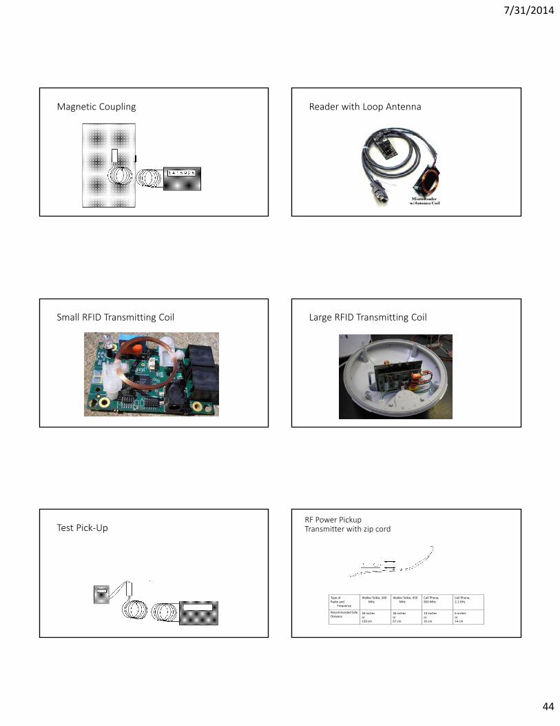
Magnetic Coupling Reader with Loop Antenna
Small RFID Transmitting Coil Large RFID Transmitting Coil
Test Pick-UpRF Power PickupTransmitter with zip cord
Type ofRadio and
Frequency
Walkie-Talkie, 200 MHz
Walkie-Talkie, 450 MHz
Cell Phone,850 MHz
Cell Phone,2.1 GHz
Recommended SafeDistance
59 inchesor150 cm
26 inchesor67 cm
14 inchesor35 cm
6 inchesor14 cm
7/31/2014
45
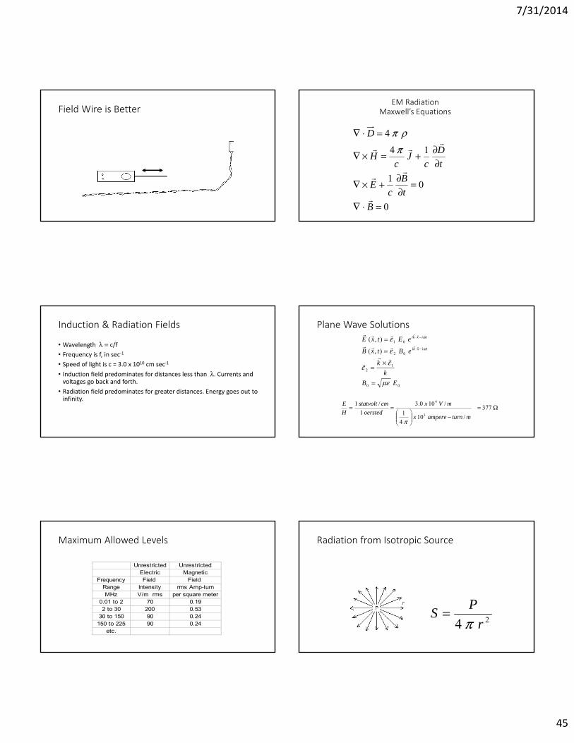
Field Wire is BetterEM Radiation
Maxwell’s Equations
0
01
144
BtB
cE
tD
cJ
cH
D
Induction & Radiation Fields
• Wavelength c/f• Frequency is f, in sec-1
• Speed of light is c = 3.0 x 1010 cm sec-1
• Induction field predominates for distances less than . Currents and voltages go back and forth.
• Radiation field predominates for greater distances. Energy goes out to infinity.
Plane Wave Solutions
00
12
02
01
),(
),(
EBk
k
eBtxB
eEtxEtixki
tixki
377
/1041
/100.31
/1
3
4
mturnamperex
mVxoersted
cmstatvoltHE
Maximum Allowed Levels
Unrestricted UnrestrictedElectric Magnetic
Frequency Field Field Range Intensity rms Amp-turnMHz V/m rms per square meter
0.01 to 2 70 0.192 to 30 200 0.53
30 to 150 90 0.24150 to 225 90 0.24
etc.
Radiation from Isotropic Source
24 rPS
7/31/2014
46
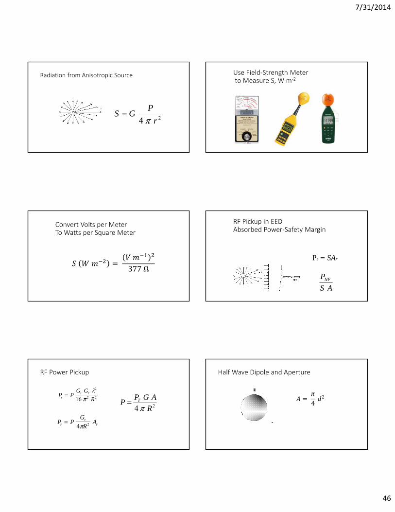
Radiation from Anisotropic Source
24 rPGS
Use Field-Strength Meterto Measure S, W m-2
Convert Volts per MeterTo Watts per Square Meter
= 377 ΩRF Pickup in EEDAbsorbed Power-Safety Margin
Pr SAr
ASPNF
RF Power Pickup
P PG G
Rrt r
2
2 216
P PGR
Art
r4 2
24 RAGPP T
Half Wave Dipole and Aperture
= 4
7/31/2014
47
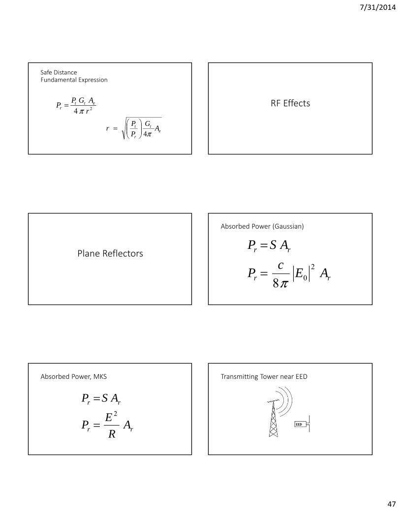
Safe DistanceFundamental Expression
24 rAGPP ett
r
et
r
t AGPPr
4
RF Effects
Plane Reflectors
Absorbed Power (Gaussian)
rr
rr
AEcP
ASP2
08
Absorbed Power, MKS
rr
rr
AR
EP
ASP2
Transmitting Tower near EED

7/31/2014
48
Direct and Reflected Waves Reflection Coefficient
11
1
EE
EEE
TOT
REFLTOT
Incorporate Reflection (Gaussian)
A Ac E A
c E A
FS
o
o FS
1
8
8 1
2
2
2 2
P
P
r
r
Incorporate Reflection (mks)
FS
FS
AR
E
AR
EAA
22
r
2
r
2
1P
P
1
Earth’s Surface
Refraction at Earth’s Surface
7/31/2014
49
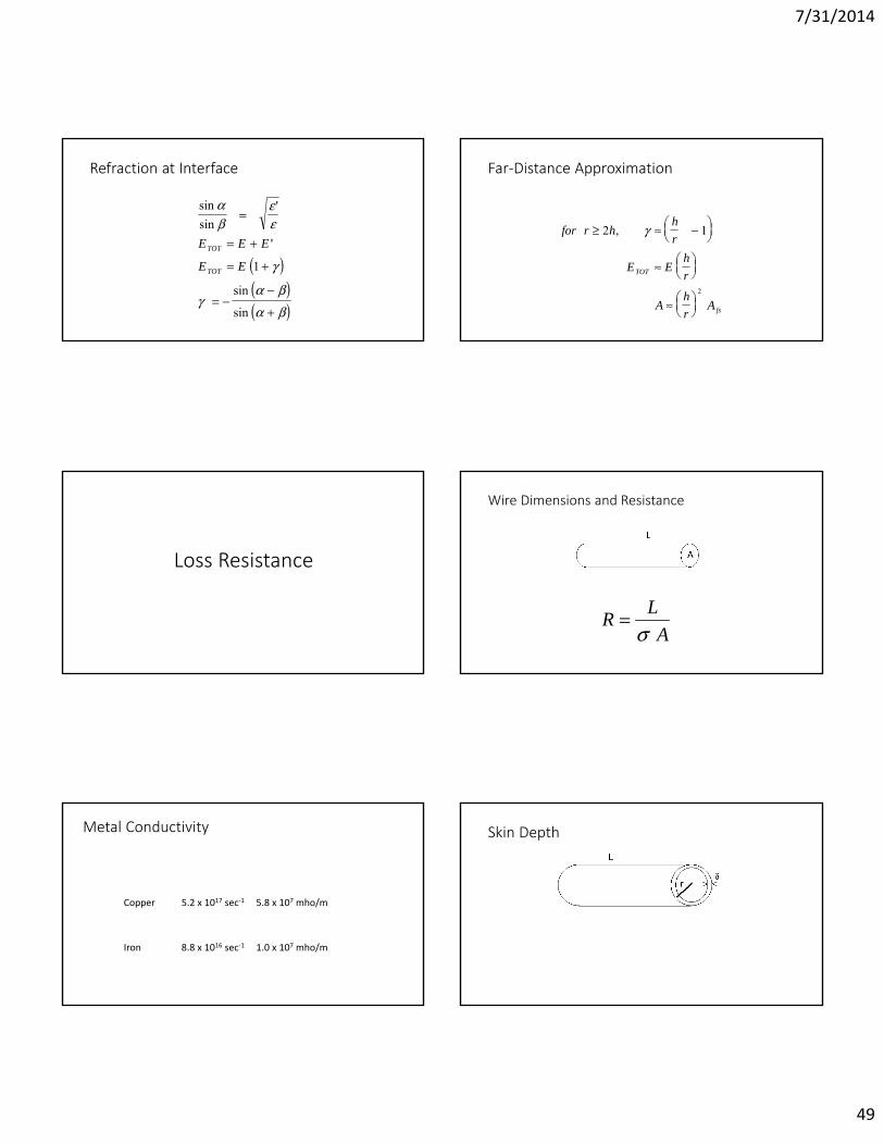
Refraction at Interface
sinsin
'
'
sin
sin
E E E
E ETOT
TOT 1
Far-Distance Approximation
for r hhr
E Ehr
Ahr
A
TOT
fs
2 1
2
,
Loss Resistance
Wire Dimensions and Resistance
ALR
Metal Conductivity
Copper 5.2 x 10¹⁷ sec-1 5.8 x 10⁷ mho/m
Iron 8.8 x 10¹⁶ sec-1 1.0 x 10⁷ mho/m
Skin Depth

7/31/2014
50
Gaussian mks
c
2 2
Copper Ironc 3.00E+10 3.00E+10 cm/sec 1 1f 5.40E+05 5.40E+05 1/sec 3.39E+06 3.39E+06 1/sec 5.20E+17 8.80E+16 1/sec 9.01E-03 2.19E-02 cm 3.5E-03 8.6E-03 inch
Skin Depth in Various Metals
Metal Conductivity σ,Mhos/ meter
Skin depth δ, In meters, for f=1010
Hz
Ag 6.17 x 10⁷ 6.42 x 10⁻⁷
Cu 5.80 6.60Au 4.10 7.85Cr 3.84 8.11Al 3.72 8.2670-30 Brass
1.57 12.7
P 0.9 17.0Solder 0.71 18.6
Loss Resistance in Round Wire(Gaussian Units)
f
rcL
rcL
rL
ALRL
22
2
Loss Resistance in Round Wire(mks units)
f
rcL
rL
rL
ALRL
222
Reduced Aperture
fsL
e ARR
RA
Matching Section
7/31/2014
51
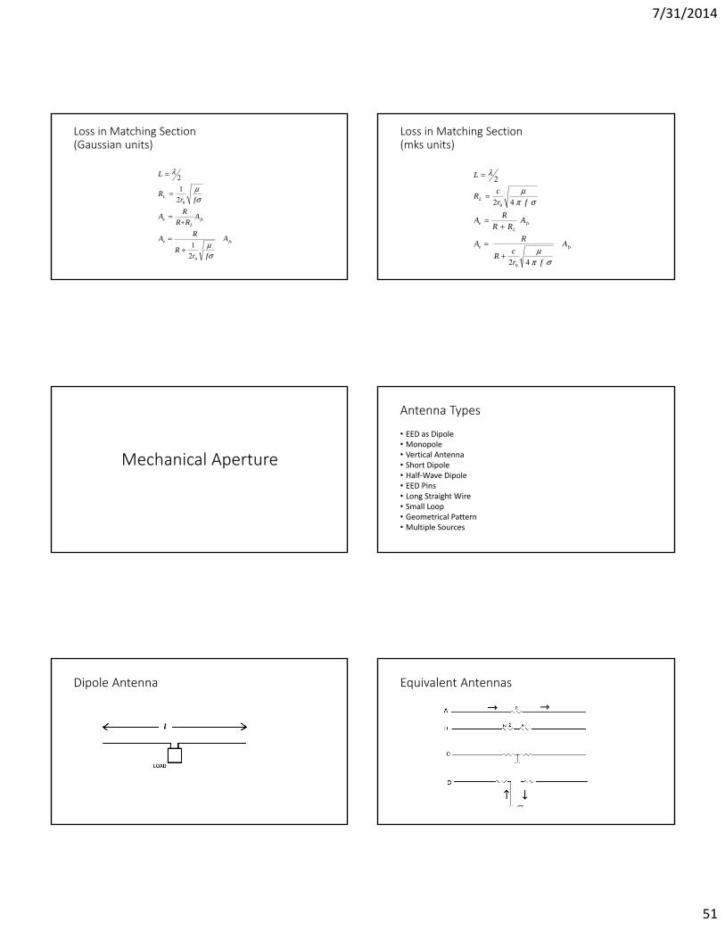
Loss in Matching Section(Gaussian units)
fse
fsL
e
L
A
frR
RA
ARR
RA
frR
L
0
0
21
21
2
Loss in Matching Section(mks units)
fse
fsL
e
L
A
frcR
RA
ARR
RA
frcR
L
42
42
2
0
0
Mechanical Aperture
Antenna Types
• EED as Dipole• Monopole• Vertical Antenna• Short Dipole• Half-Wave Dipole• EED Pins• Long Straight Wire• Small Loop• Geometrical Pattern• Multiple Sources
Dipole Antenna Equivalent Antennas

7/31/2014
52
Vertical Whip Antenna Half-Wave Dipole Works Best
2
cf
f c 2
Half-Wave Dipole Formulae
G = 1.65
A
2
4 G
A 165 2.
Incorporate Other Effects
22
0
2
2
222
11
214
65.1
114
frR
RfcA
RRRGA
e
Le
Gain & Radiation Resistanceof Short Dipole
GM ( / )3 2
3
22
20
220
6
21
12
cfd
R
RIP
cdkI
P
EED Pins –Circular Aperture, orWorst Case Half Wave Dipole
7/31/2014
53
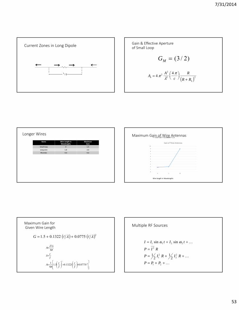
Current Zones in Long Dipole Gain & Effective Apertureof Small Loop
GM ( / )3 2
AA
cR
R Re
L
442
2
2 2
Longer Wires
Name Wire Length in Wavelengths
MaximumGain
Small loop 0 1.5Long wire 1.8 2.0Rhombic 9.0 9.0
Maximum Gain of Wire Antennas
1.8 2
9
0
1
2
3
4
5
6
7
8
9
10
0 2 10
Gain of Three Antennas
Wire length in Wavelengths
Y = 0.0772x2 + 0.13889x + 1.5
Maximum Gain forGiven Wire Length
20775.01322.05.1 G
22
2
0775.01322.05.141
4
fc
fcA
fc
GA
Multiple RF Sources
21
22
21
2
2211
21
21
sinsin
PPP
RIRIP
RIP
tItII
7/31/2014
54
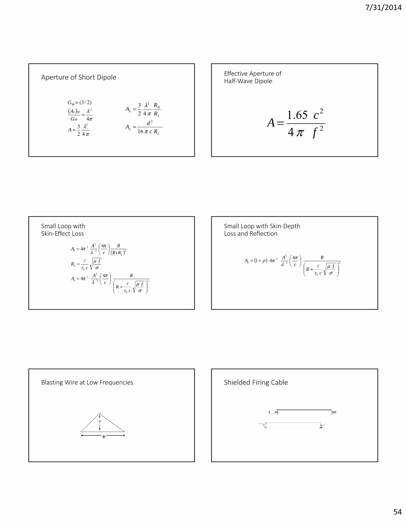
Aperture of Short Dipole
423
4
)2/3(
2
2
A
GA
G
M
Mr
M
Le
L
Re
RcdA
RR
A
16
423
2
2
Effective Aperture ofHalf-Wave Dipole
2
2
4 65.1fcA
Small Loop withSkin-Effect Loss
2
0
2
22
0
22
22
44
44
fcr
R
Rc
AA
fcr
R
RRR
cAA
e
L
Le
Small Loop with Skin-DepthLoss and Reflection
2
0
2
22 441
f
crR
Rc
AAe
Blasting Wire at Low Frequencies Shielded Firing Cable
7/31/2014
55
Cable Faults Wireline with Faults
RF Safe Distance
Model EED System Aperture:
• Short dipole• Half-wave dipole• Long straight wire• Wire longer than wavelength, not straight• Small loop• Mechanical aperture
Aperture of EED Alone
• Model as short dipole of length d• Use maximum dimension of EED as d
RcdA16
2
Safe DistanceFundamental Expression
24 rAGPP ett
r
et
r
t AGPPr
4
7/31/2014
56
Use Known No-Fire Level-
In “Safe Distance” equation, insert EED’s PNFvalue for received power Pr
EXAMPLE CALCULATION• Electric detonator• One ohm bridgewire• 0.2 ampere no-fire current level• Copper leadwires• Extended leadwires and shot-line (worst case)• Leadwires are twisted together at end• Nearby AM radio broadcasting station• How close can we get?
Further Assumptions
• AM radio band is 0.54 to 1.6 MHz. As a worst case, we say frequency is 1.6 MHz. Thus, wavelength is about 188 meters.
• AM radio transmitters are often very directional. As a worst case, we say Gt =10.
• Transmitter power 50,000 watts – legal max• As a worst case, we assume someone has picked up one of the EED
wires, leaving the other on the ground, making a triangular loop.
PICKUP LOOP
Particulars of Pickup Loop
• Loop is much smaller than a wavelength
• Therefore, we will use our aperture formula for a small loop
• Loop area 2.3 m2
• Perimeter Length 7.3 m
Safe Distance Formula
et
r
t AGPPr
4
2
0
12
fcr
R
RcP
PGc
fArr
t
7/31/2014
57
Safe Distance from AM TransmitterSpeed of light 3E+10 cm/secTransmitting antenna gain 10No-fire power 0.04 WattEED resistance 1.11E-12 sec/cmLoop length 735 cmWire radius 0.0405892 cmWire metal permeability 1Wire metal conductivity 5.2E17 1/sec Power------------------Safe-- ------Distance
Watts cm feet meters1000 1.09E+04 358 1094000 2.18E+04 716 2185000 2.44E+04 801 244
10000 3.45E+04 1132 34525000 5.46E+04 1790 54650000 7.72E+04 2532 772
Recommended Distances from Commercial AM Broadcast
T ransmitting Antennas 0.54 to 1.6 MHz
0100200300400500600700800900
0 10000 20000 30000 40000 50000 60000
Transmitter Power Watts
Saf
e D
ista
nce
Met
ers
References
• Safety Guide for the Prevention of Radio Frequency Radiation Hazards in the Use of Commercial Electric Detonators (Blasting Caps). Safety Library Publication No. 20. Institute of Makers of Explosives (IME), 1120 Nineteenth St. NW, Suite 310, Washington, DC 20036-3605, U.S.A.
• IEEE Recommended Practice for Determining Safe Distances from Radio Frequency Transmitting Antennas When Using Electric Blasting Caps During Explosive Operations. ISBN 0-7381-3422-8; IEEE Product No. SH95045-TBR;IEEE Standard No. C95.4-2002
Electroexplosives:Functioning, Reliability and Hazards
Testing for RF SafetyPresented by Franklin Applied Physics, Inc.
Instrumented EEDs Factors Affecting RF Safety

7/31/2014
58
Anechoic ChamberBand 1H B P run 34476
0
0.1
0.2
0.3
0.4
0.5
0.6
0.7
0.8
0.9
19:55.2 20:38.4 21:21.6 22:04.8 22:48.0 23:31.2 24:14.4 24:57.6
time (minutes:seconds)100 88.3 77.6 68.2 60.0 52.7 46.2 40.8 35.6 31.6 27.7 24.2 21.6
frequency (MHz)
rela
tive
volts
FprtnRFpassLFdvr1dvr2PRTpcLpassRsideLSYNCH
Electroexplosives:Functioning, Reliability, and
Hazards:
Non-destructive
Tests
Presented by Franklin Applied Physics, Inc.
• The firing of an electroexplosive device is irreversible, non-repeatable, and not fully predictable in advance. A number of indirect methods have been developed that can determine whether a given EED might be defective, without actually firing it. Joseph McLain
7/31/2014
59
Bridgewire Resistance Test
• Special ohmmeter to limit current• < 1 milliampere for hot-wire device• < 10 microamps for carbon bridge• Check every item• - on production line• - before and after test exposure• - system check• RF Impedance
Thermal Transient Response TestRosenthal Equation
• C is heat capacity of the system• T is temperature above ambient• t is time• a is heat loss coefficient of the system• b is thermal coefficient of resistance of bridgewire material• Ro is initial resistance of the EED
)1()( 2 bTRItPaTC odtdT
Solutions for constant current
If t<<C/a i.e. very short time
• If t is very large i.e. equilibrium situation
tC
bRIabRIa
RIT o
o
o2
2
2
exp1
tyHeatCapaciEnergyt
CRIT o
2
powerbRIa
RITo
o
2
2
Increasing “a” decreases equilibrium temperature
Increasing C increases time to equilibrium Increasing Ro increases equilibrium temperature
7/31/2014
60
Leak Test
• Keep out moisture• Hermetically sealed• Seals between different materials –• metal, glass or ceramic, plastics, etc.• Helium• Krypton-85• Red dye
X-rays of EEDs
7/31/2014
61
Testing EEDs• Random sample from large lot of EEDs• Sampling by attributes• MIL-DTL-23659D• Don’t re-use test samples
Turn-On Time
• Bridgewire posts
• Current Heating
• Conduction Cooling
RIkdtdT 2
0TT
dtdT
• Current rise rate
• Combine effects
tI
022 TTRtk
dtdT
Alternative Explanations
• Current overshoot
• Dudding
0
0.2
0.4
0.6
0.8
1
1.2
1.4
1.6
0 1 2 3 4
Milliseconds
Am
pere
s
Electrical Test Stimuli for EEDs
•All-fire – Short Time•No Fire – Long Time•ESD•Constant Current or Voltage•Constant Power•Capacitor Discharge•RF Power
ESD Tester

7/31/2014
62
Photo of ESD Tester Simulator Set Up-Leads should be short!
HV Lead in Conduit-Not Recommended! ESD Pin-to-Pin Test
Current,Instantaneous Power
( ) = = ( )
EnergyBridge Wire Temperature= 2 = 2 + + 2 +
= 2 +
7/31/2014
63
Constant-Current Tester
1
121
1
2121
RVI
RR
RVI
RRRR
VI
Constant-Voltage Tester
Constant-Power Test
•Semiconductor bridge (SCB) initiators•Conductive mix initiators•Ratio of voltage to current (apparent resistance)
depends on temperature
Power as Function of Constant Voltage or Current
• = • =
Constant Power Tester Sample Data
7/31/2014
64
Capacitor-Discharge Tester
Capacitor-Discharge Test
DISCHARGE TIME < THERMAL TIME CONSTANT
RF Voltage and Current RF Voltage and Power
tVV cos0
dtIVT
PTt
t
0
1
RF Period
2T
RF Voltage and Current out of Phase
tIItVV
coscos
0
0
cos21
coscos1
1
00
00
0
0
IVP
dtttIVT
P
dtIVT
P
Tt
t
Tt
t
7/31/2014
65
Measure Voltage, Current, and Phase Angle. V2= Phase Difference
Phase Angle and Measured Average RF Power
Dd 2
DdVVP
IVP
2cos2
cos21
21
00
Lead Length for EED RF Tests
EEDLEAD RR
Allowable Lead Length
f
crR
rR
LEAD
LEAD
2
22
rx
Rf
cm
rx
Rf
MHzohm
EED
EED
10 7 10
12 10
1832
4
. sec
.
Output Tests on EEDs
• Squibs - hot gas – closed bomb
• Detonators – shock wave – witness
7/31/2014
66
Current and Pressure Card Gap Test
Data From Card Gap Test
Number of Cards Gap Width, Inches Number of Successful Ignitions
Number of Trials with no Ignitions
0 0.00 1 01 0.01 3 12 0.02 4 33 0.03 2 34 0.04 1 25 0.05 0 1
Timing
Light Output AfterCapacitor Discharge
Light from 2 EEDsFired in Parallel

7/31/2014
67
Light Sensor Module Light Sensor System
Firing Chamber Safety Factor Sealed Tube
Ultimate Tensile Strength
=
Thin-Walled Metal Tube

7/31/2014
68
Upper Half of Tube
= 2 ℓ= sin ℓ = 2 ℓ
Barlow’s Formula for Burst Pressure= = 2
Tube CalculationUltimate tensile strength
58,000 psi 4.0 x 10¹⁰ Pa
Tube radius 10 inches 25.4 cmTube wall thickness 0.19 inches 4.8 mmBursting pressure 1088 psi 7.5 x 10⁸ Pa
Pressure from 3 grams HE
→ 3 + 3 + 3 3 = 0.0135 → 0.12 =
Safety Factor for Tube(Greater for Test Chamber)
= = 194One-Level Test
UniformityFew DefectivesPoisson DistributionTest Lots with Defectives
7/31/2014
69
EEDs with Varying Resistance
• Divide test units into two lots by resistance• Perform all-fire test on low-resistance lot• Perform no-fire test on high-resistance lot
RIP 2
Assumption: Few Defectives
• Large population with few defectives• Fraction of defectives • Value of is small• Sample size n• We find number of defectives x• Sample size n >> x• Product n is small (less than 25)
What We Need to Know
• What value of x, i.e., how many defectives, can we reasonably expect to find?
• If we obtain a certain number of defectives x, what can we say about the value of ?
• How many items n do we need in our test lot?
Poisson Distribution
!)|(
xexp
nx
Probability ofZero Defectives
eep!0
)|0(0
Probability ofOne Defective
eep!1
)|1(1
Probability of One or Fewer Defectives:
eepp )|0()|1(
Zero Defectives, Lot Size 10
0.065 0.2730.130 0.204
0.195 0.1630.260 0.135
0.325 0.1120.390 0.0940.455 0.079
0.520 0.0650.585 0.0540.650 0.043
0.715 0.0340.780 0.025
0.845 0.0170.910 0.009
eep!0
)|0(0
0.000
0.050
0.100
0.150
0.200
0.250
0.300
0.000 0.500 1.000
Alpha
Thet
a

7/31/2014
70
Reliability & Confidence230.0100.0 for
230.0100.0 for230.0100.0 thatyprobabilit
230.0900.0 thatyprobabilit770.0)1(900.0 thatyprobabilit
%77%90 yreliabilitthatconfidence
Probability ofc or fewer defectives
c
x
x
xe
n
0 !
Confidence and Reliability
• If we draw a sample of size n from a population with a defective fraction , then the probability that we will find c or fewer defective items is .
• If we test n items, from a population with a defective fraction less than or equal to , then the probability that we will obtain c or fewer defectives is (1- ).
• If we draw a sample of size n, and we find c or fewer defective items, then the probability is that the population has defective fraction ≥
Another Way of Putting It
• If we draw a sample of size n, and we find c or fewer defective items, then we have 100(1- confidence that the population has defective fraction ≤
• If we draw a sample of size n, and we find c or fewer defective items, then we have 100(1- confidence that the population has reliability ≥ 100(1-
Confidence and Reliability
Confidence ↔ Confidence = 100(1 - )%
Reliability ↔ Reliability = 100(1 - )%
Two or Fewer Defectives
2
2
eee
n
Reliability % 90 95 95 99 99 99.9 99.9
Confidence % 90 90 95 90 95 90 95θ 0.1 0.05 0.05 0.01 0.01 0.001 0.001
α 0.1 0.1 0.05 0.1 0.05 0.1 0.05
Lot size n 53 106 126 532 629 5322 6296

7/31/2014
71
Expose 500 to AF, all but 2 fired: Reliability w/ 90% confidence?
9894.01
010644.0500322.5
322.52
110.0
!
210.0%90)%1(100
2
2
0
n
n
eee
xe
c
x
x
One or Fewer Defectives
een
Reliability % 90 95 95 99 99 99.9 99.9
Confidence % 90 90 95 90 95 90 95
θ 0.1 0.05 0.05 0.01 0.01 0.001 0.001
α 0.1 0.1 0.05 0.1 0.05 0.1 0.05
Lot size n 39 78 95 389 474 3890 4744
Zero Defectives
en
Reliability % 90 95 95 99 99 99.9 99.9
Confidence % 90 90 95 90 95 90 95
θ 0.1 0.05 0.05 0.01 0.01 0.001 0.001
α 0.1 0.1 0.05 0.1 0.05 0.1 0.05
Lot size n 24 46 60 230 300 2303 2996
Examples of ValuesNot in Tables
• Find lot size• Find Confidence Level• Find Reliability• Increase Lot size
Find Lot Size
• AF=3.5A, 97.5% Reliability, 92%Confidence• Equation for Zero Defectives
en
Reliability % 97.5
Confidence % 92
θ 0.025
α 0.08
Lot size n 101
Find Confidence• Test 30 squibs (n=30). None fires.• No-fire level (95% reliability) is 0.400 A• What confidence that squibs meet spec?• Probability for zero defectives
en
Reliability % 95
Confidence % 77.69
θ 0.05
α 0.223
Lot size n 30
7/31/2014
72
Find Reliability
• What is reliability of firing unit?• 22 caps; all of them fire• Use formula for zero defectives
en
Reliability % 89.53
Confidence % 90
θ 0.1047
α 0.10
Lot size n 22
Increase Lot Size
• Specify DC no-fire current 0.150 ampere• Specify 90% reliability, 90% confidence• “Zero Defectives” table: 24 squibs• Expose 24, the last one fires• Expose more – how many?• “One or Fewer Defectives” table: 39• We must obtain & expose 15 more• If no more fire, specification is met.
Drawbacks
• Many useful conclusions from the kind of test where we expose explosive devices to a single stimulus level.
• This kind of test does not tell us what might happen at a different level of stimulus.
• Large number of explosive items required, particularly when we test high levels of reliability, at high levels of confidence
Testing at Many Stimulus Levels
How to determineall-fire and no-fire levels for EEDs
Cumulative Firing Probability
0
10
20
30
40
50
60
70
80
90
100
0 10 20 30 40 50 60 70 80 90 100
Stimulus Value, Arbitrary Units
Perc
ent F
iring
Pro
babi
lity
Fitting Data
0
10
20
30
40
50
60
70
80
90
100
0 10 20 30 40 50 60 70 80 90 100
Stimulus Value, Arbitrary Units
Perc
ent F
iring
Pro
babi
lity
7/31/2014
73
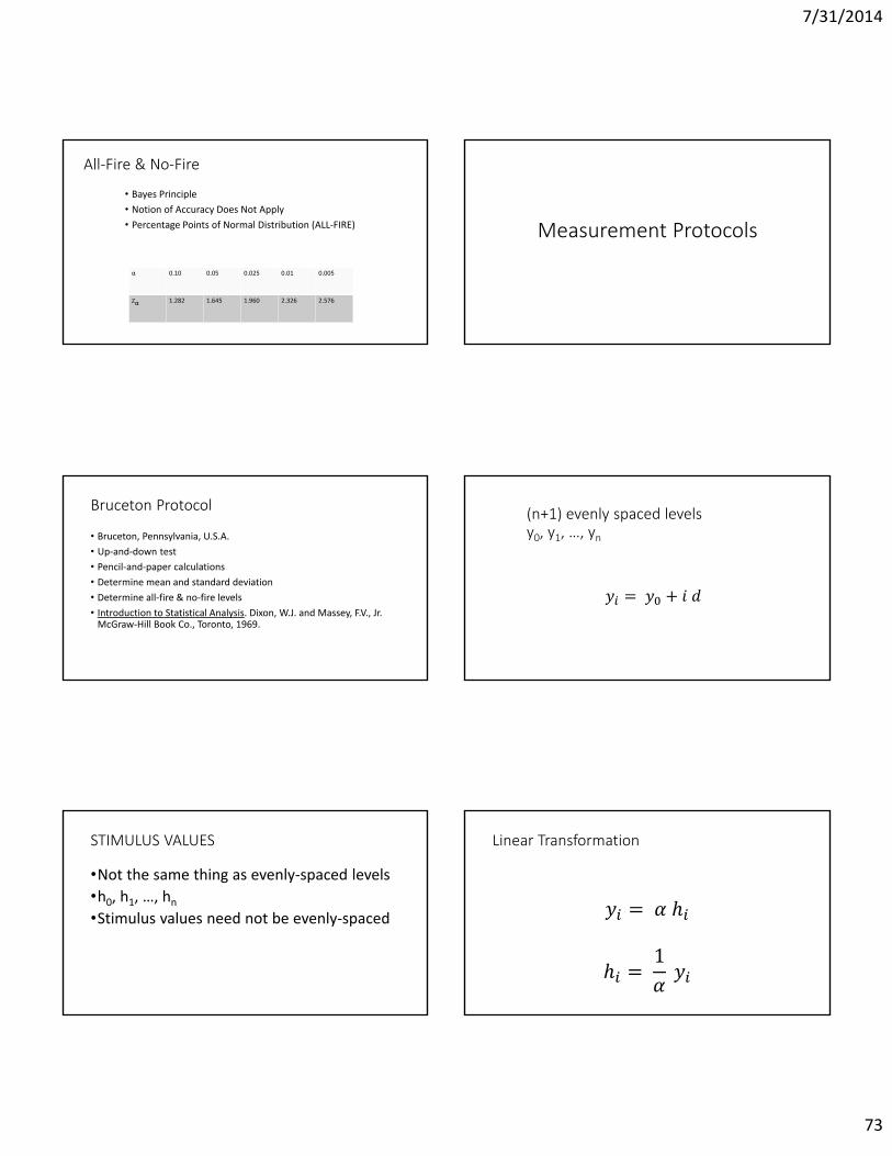
All-Fire & No-Fire
• Bayes Principle• Notion of Accuracy Does Not Apply• Percentage Points of Normal Distribution (ALL-FIRE)
α 0.10 0.05 0.025 0.01 0.005
Zα 1.282 1.645 1.960 2.326 2.576
Measurement Protocols
Bruceton Protocol
• Bruceton, Pennsylvania, U.S.A.• Up-and-down test• Pencil-and-paper calculations• Determine mean and standard deviation• Determine all-fire & no-fire levels• Introduction to Statistical Analysis. Dixon, W.J. and Massey, F.V., Jr.
McGraw-Hill Book Co., Toronto, 1969.
(n+1) evenly spaced levelsy0, y1, …, yn
= +
STIMULUS VALUES
•Not the same thing as evenly-spaced levels•h0, h1, …, hn•Stimulus values need not be evenly-spaced
Linear Transformation
= ℎℎ = 1
7/31/2014
74
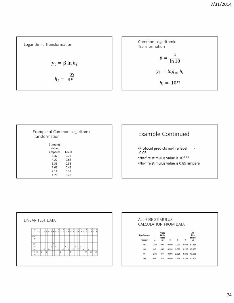
Logarithmic Transformation
= β ln ℎℎ =
Common Logarithmic Transformation= 1ln 10= ℎℎ = 10
Example of Common Logarithmic Transformation
Stimulus Value,
amperes Level5.37 0.734.27 0.633.39 0.532.69 0.432.14 0.331.70 0.23
Example Continued
•Protocol predicts no-fire level -0.05
•No-fire stimulus value is 10-0.05
•No-fire stimulus value is 0.89 ampere
LINEAR TEST DATA
DUT 1 2 3 4 5 6 7 8 9
10
11
12
13
14
15
16
17
18
19
20
21
22
23
24
25
Level
30 X25 O X X X X20 X O X O X O O X X15 X O O O O O X X10 O O
ALL-FIRE STIMULUSCALCULATION FROM DATA
ConfidenceProbability
All-Fire
Percent Perce
nt k lStimul
us
95 0.95 99.9 0.999 3.090 1.645 51.335
90 0.9 99.9 0.999 3.090 1.282 48.383
95 0.95 99 0.990 2.326 1.645 43.565
90 0.9 99 0.990 2.326 1.282 41.303
7/31/2014
75
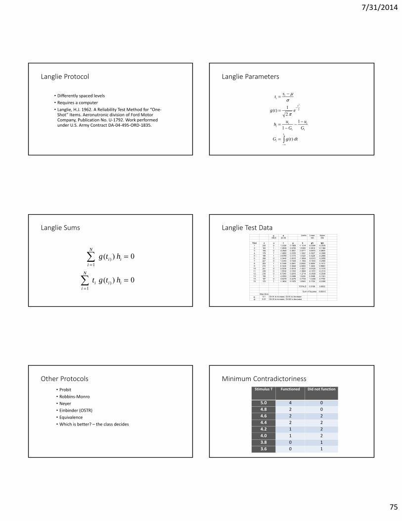
Langlie Protocol
• Differently spaced levels• Requires a computer• Langlie, H.J. 1962. A Reliability Test Method for “One-
Shot” Items. Aeronutronic division of Ford Motor Company, Publication No. U-1792. Work performed under U.S. Army Contract DA-04-495-ORD-1835.
Langlie Parameters
it
i
i
i
i
ii
t
ii
dttgG
Gu
Guh
etg
st
)(
11
21)( 2
2
Langlie Sums
0)(
0)(
1)
1)
i
N
iii
i
N
ii
htgt
htg
Langlie Test Data Limits: Lower Upper
199.8 20.39 100 350
Trial s u t g h gh tgh1 225 0 1.2359 0.1859 -1.1214 -0.2084 -0.25762 163 1 -1.8048 0.0783 1.0369 0.0812 -0.14653 194 0 -0.2845 0.3831 -2.5771 -0.9874 0.28094 178 1 -1.0692 0.2253 1.1662 0.2627 -0.28095 186 1 -0.6768 0.3173 1.3320 0.4226 -0.28606 268 0 3.3448 0.0015 -1.0004 -0.0015 -0.00507 227 0 1.3340 0.1639 -1.1002 -0.1803 -0.24058 203 1 0.1569 0.3941 2.2850 0.9004 0.14139 215 1 0.7455 0.3022 4.3860 1.3253 0.988010 241 0 2.0206 0.0518 -1.0221 -0.0529 -0.107011 228 0 1.3830 0.1533 -1.0909 -0.1672 -0.231312 216 0 0.7945 0.2910 -1.2714 -0.3699 -0.293913 158 1 -2.0500 0.0488 1.0206 0.0498 -0.102114 187 0 -0.6278 0.3276 -3.7724 -1.2358 0.775815 172 1 -1.3634 0.1575 1.0945 0.1724 -0.2350
TOTALS 0.0108 0.0002
Sum of Squares 0.00012Step Size
0.1 Ctrl-A to increase, Ctrl-S to decrease 0.01 Ctrl-N to increase, Ctrl-M to decrease
Other Protocols• Probit• Robbins-Monro• Neyer• Einbinder (OSTR)• Equivalence• Which is better? – the class decides
Minimum ContradictorinessStimulus T Functioned Did not function
5.0 4 04.8 2 04.6 2 24.4 2 24.2 1 24.0 1 23.8 0 13.6 0 1
7/31/2014
76
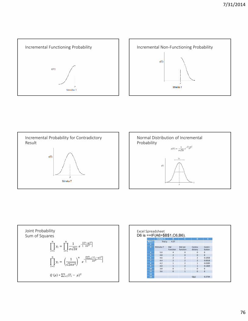
Incremental Functioning Probability Incremental Non-Functioning Probability
Incremental Probability for Contradictory Result
Normal Distribution of Incremental Probability = 12 ( )
Joint ProbabilitySum of Squares
= 12 = 12 ∑
= ∑ −
Excel SpreadsheetD6 is =+IF(A6>$B$1,C6,B6).
Column A B C D ERow 1 Trial 4.37
23 Stimulus T Did
FunctionDid notfunction
Contra-dictory
Contri-bution
4 5.0 4 0 0 05 4.8 2 0 0 06 4.6 2 2 2 0.10587 4.4 2 2 2 0.00188 4.2 1 2 1 0.02899 4.0 1 2 1 0.1369
10 3.8 0 1 0 011 3.6 0 1 0 01213 Q() 0.2734
7/31/2014
77
Uses of No-Fire & All-Fire Levels
• For safety, ensure no extraneous signal reaching the EED exceeds the no-fire level.
• For reliability, design your firing circuit so that its output exceeds the all-fire level.
Optimal Firing Circuit
2
2VCE
Safety Margin
Input (Sensitivity) Tests
•Quantal Response•Important to know exactly how sensitive•Tests on EEDs
Continuous Statistics
• Sample of EEDs• On each one, turn up the power until it fires• Record final (firing) power level• Sample (x1, x2, …, xn)• Assume sample from normal distribution N( ).
Normal Distribution
7/31/2014
78
Estimate Population Parameters• Values represent entire population
2
1
21
n
jj xxsn
n
iix
nx
1
1
Standard Normal Distribution
Percentage Points ofNormal Distribution
( ) ,
( ) ( )
z e z
P z z z dz
z
z
12
22
Sample Comparison TestSensitivity same?Contamination?
Possibility : 2 Bruceton tests
References
• Quantitative Effect of Gritty Contaminants on the Sensitiveness of High Explosives to Initiation by Impact. Henry J. Scullion, Journal of Applied Chemistry and Biotechnology, 1975, v. 25, pp. 503-508.
• Manual of Tests and Criteria. Recommendations on the Transport of Dangerous Goods. ST/SG/AC.10/11/Rev.3. United Nations, New York and Geneva, 1999. Appendix 2, “Bruceton and Sample Comparison Methods.”
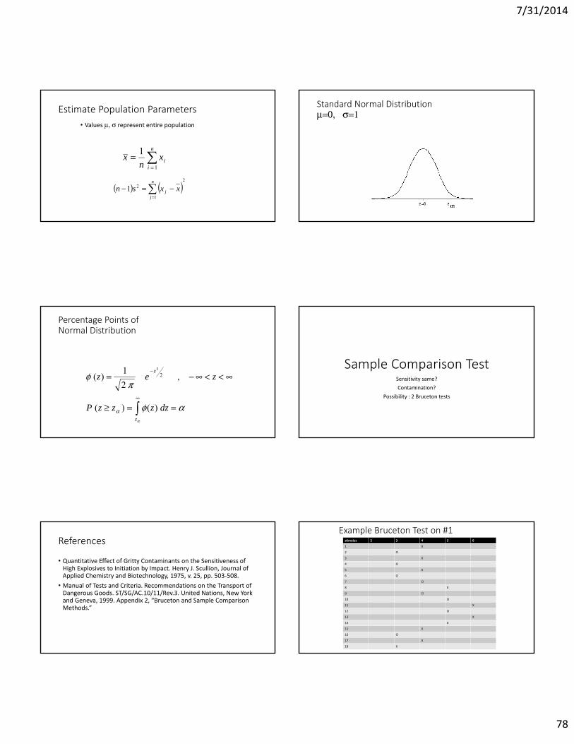
Example Bruceton Test on #1stimulus 2 3 4 5 6
1 X
2 O
3 X
4 O
5 X
6 O
7 O
8 X
9 O
10 O
11 X
12 O
13 X
14 X
15 X
16 O
17 X
18 X

7/31/2014
79
Samples of #1 and of #2Stimulus 2 3 4 5 6
Explosive 1 2 1 2 1 2 1 2 1 2
1 X O
2 O O
3 X O
4 O O
5 X O
6 O O
7 O O
8 X O
9 O X
10 O O
11 X X
12 O O
13 X O
14 X O
15 X O
16 O O
Underline Differing ResultsStimulus 2 3 4 5 6
Explosive 1 2 1 2 1 2 1 2 1 2
1 X O
2 O O
3 X O
4 O O
5 X O
6 O O
7 O O
8 X O
9 O X
10 O O
11 X X
12 O O
13 X O
14 X O
15 X O
16 O O
17 X O
One Bruceton Test
• If ignition, decrease stimulus• If no ignition, increase stimulus• Subject sample of 2nd explosive to same stimulus as sample of 1st
explosive• Use only pairs of results with different responses• Pairs n, explosive A has fewer ignitions• Have x cases where A ignited, B did not
Distribution of ResultsExample: BBBBABBBBB
)( xnx
Probability
• Probability that first one will be B is ½• Probability that second one will be A is ½• Probability first two will be BA is (½) * (½) • Probability of any given sequence of n As and Bs is (1/2)n
Number of CombinationsProbability of x A’s in n Trials
)!(!!
xnxn
!!!
21)(
xnxnxp n
7/31/2014
80
Probability of x, given n=10
0
5
10
15
20
25
30
0 2 4 6 8 10 12
x (number of A's)
Prob
abili
ty p
erce
nt
Cumulative Probability“x or fewer” - Example for n=10
xi
i n ininfewerorxp
0 !!!
21)(
0
20
40
60
80
100
120
0 2 4 6 8 10 12
x (number of A's) or fewer
Prob
abili
ty P
erce
nt
Confidence that Coin is not “Fair”
xi
i n ininK
0 !!!
211100
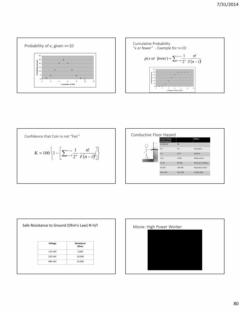
Conductive Floor HazardCurrent Values(milliamperes)
Effects
AC (60 Hz) DC
0-1 0-4 Perception
1-4 4-15 Surprise
4-21 15-80 Reflex action
21-40 80-160 Muscular inhibition
40-100 160-300 Respiratory block
Over 100 Over 300 Usually fatal
Safe Resistance to Ground (Ohm’s Law) R=V/I
Voltage ResistanceOhms
110 VAC 5,000
220 VAC 10,000
480 VAC 22,000
Movie: High Power Worker
7/31/2014
81
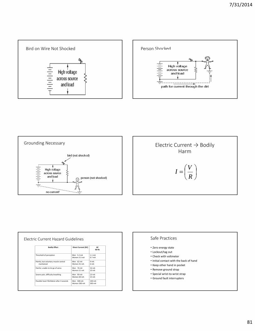
Bird on Wire Not Shocked Person Shocked
Grounding Necessary Electric Current → Bodily Harm
RVI
Electric Current Hazard Guidelines
Bodily Effect Direct Current (DC) AC60 Hz
Threshold of perception Men 5.2 mAWomen 3.5 mA
1.1 mA0.7 mA
Painful, but voluntary muscle control maintained
Men 62 mAWomen 41 mA
9 mA6 mA
Painful, unable to let go of wires Men 76 mAWomen 51 mA
16 mA10 mA
Severe pain, difficulty breathing Men 90 mAWomen 60 mA
23 mA15 mA
Possible heart fibrillation after 3 seconds Men 500 mAWomen 500 mA
100 mA500 mA
Safe Practices
• Zero energy state• Lockout/tag out• Check with voltmeter• Initial contact with the back of hand• Keep other hand in pocket• Remove ground strap• Special wrist-to-wrist strap• Ground fault interrupters
7/31/2014
82
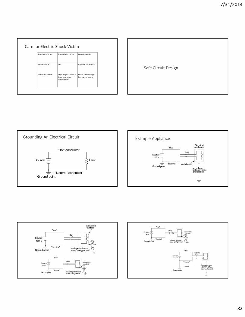
Care for Electric Shock Victim
Frozen to Circuit Turn off electricity Dislodge victim
Unconscious CPR Artificial respiration
Conscious victim Physiological shock –keep warm and comfortable
Heart attack danger for several hours
Safe Circuit Design
Grounding An Electrical Circuit Example Appliance
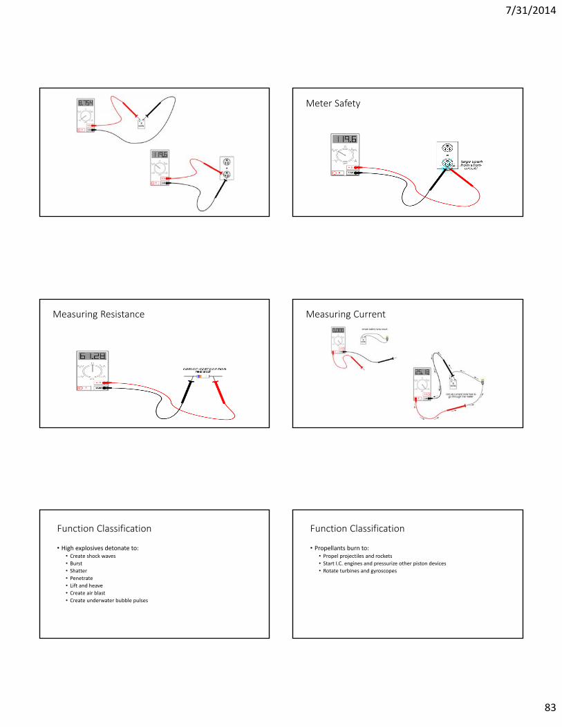
7/31/2014
83
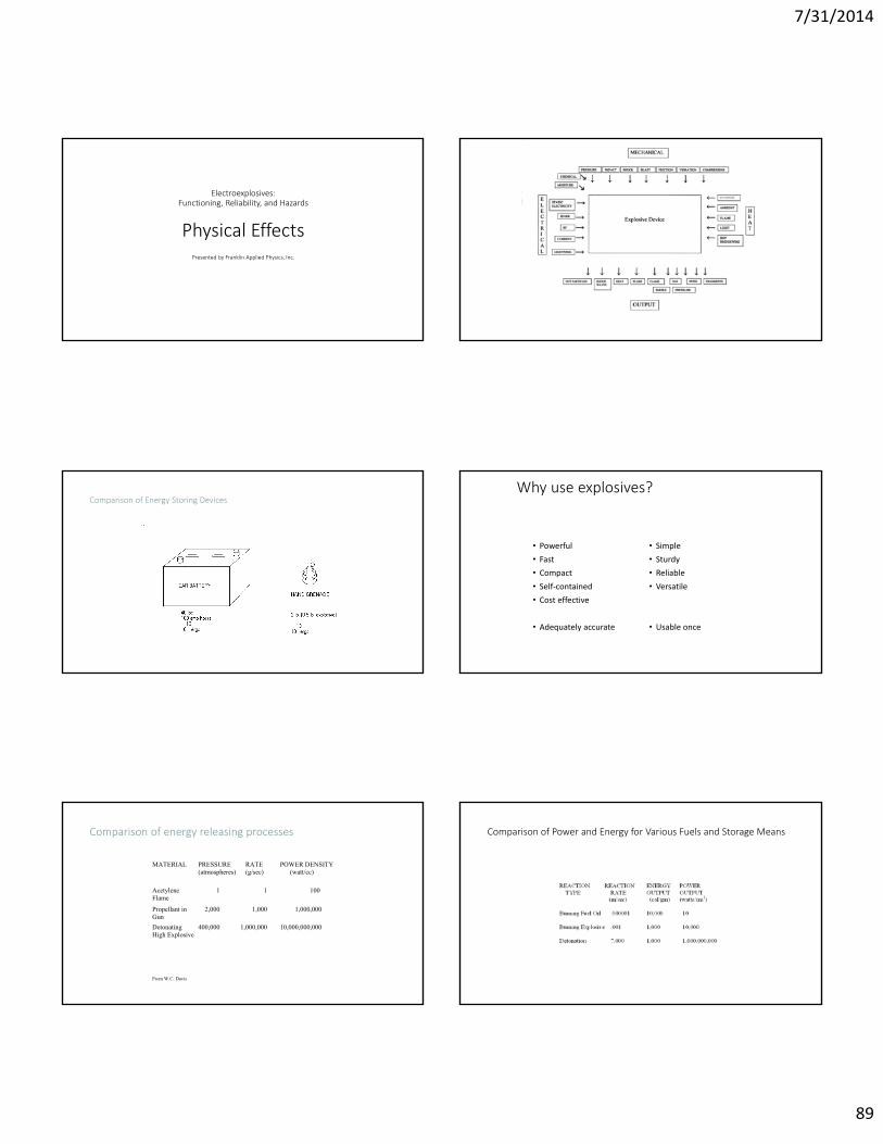
Meter Safety
Measuring Resistance Measuring Current
Function Classification
• High explosives detonate to:• Create shock waves• Burst• Shatter• Penetrate• Lift and heave• Create air blast• Create underwater bubble pulses
Function Classification
• Propellants burn to:• Propel projectiles and rockets• Start I.C. engines and pressurize other piston devices• Rotate turbines and gyroscopes

7/31/2014
84
Function Classification
• Pyrotechnics burn to:• Ignite propellants• Produce delays• Produce heat, smoke, light and/or noise
Sensitivity Classification
• A primary high explosive can detonate easily.• A secondary high explosive can detonate, but less easily.• We do not require a propellant explosive to detonate at all.• It is probably true that all primary explosives are capable of
detonation. We do not require this. We require only deflagration.
Hershey Bypass IOC 3.8 MT 01 Oct 1991
IOC 5.0 MT 21 Dec 2005 Exploding Whale

7/31/2014
85
Primaries
•Azides•Perchlorates•Organometallics
Electroexplosives:Functioning, Reliability, and Hazards
Chemistry
Presented by Franklin Applied Physics, Inc.
Molecular Energy Levels
Burning (oxidation)
• 2H2 + O2 → 2H2O
• C3H8 + 5O2 → 4H2O + 3CO2
• (propane)
• Exothermic reactions
Molecular Energy Levels

7/31/2014
86
Explosive and pyrotechnic mixtures
• Black powder
• ANFO
• Emulsions
• Thermite
• Safety matches
Some explosive molecules
• RDX C3H6N6O6
• PETN C5H8N4O12
• Lead styphnate C6H3N3O9Pb
• Mercury fulminate C2N2O2Hg
“Green” explosives
• Many primaries have heavy metals• DBX-1• Substitute for lead azide• Similar properties• Less reactive with other substances (copper, some secondary
explosives)
TNT - Trinitrotoluene 2C7H5N3O6 3N2 + 5H2O + 7CO + 7C
• Other products include:• H2
• NH2
• NH3
• HCN• NO• NOx
• CO2
• CH4
• CH3OH• C2H2
• C2H4
• C2H6
• CH2O• CH2O2
• C2H5OH
Oxygen Balance
• Ω (%) = 100 AWO [ NO – 2NC -½NH ]• MWexpl
AWO = 16.000 MWexpl = 12.01NC + 1.008 NH + 14.008NN + 16.000 NO
• Ω = 0 maximum energy output
• Ω < 0 underoxidized, fuel rich
• Ω > 0 overoxidized, fuel lean

7/31/2014
87
• Nitroglycol C2H4O6N2 Ω = 0
• TNT Ω < 0
• Nitroglycerin C3H5O9N3 Ω > 0
TNT - Trinitrotoluene 2C7H5N3O6 3N2 + 5H2O + 7CO + 7C
• Afterburn:
• 2CO + O2 2CO2
• C + O2 CO2
First Law of Thermodynamics
• Energy cannot be created or destroyed, it can only be transformed from one form of energy into another
• The total energy of a closed system remains constant• (conservation of energy)
• Heat of formation = internal energy of final state minus sum of internal energies of initial components
• (a negative quantity)
Molecular Energy Levels
• Heat of reaction = [Σ heat of formation of products] – [Σ heat of formation of reactants]
• Negative for exothermic reaction• Often labeled Q or ΔH

7/31/2014
88
Molecular Energy Levels
• Heat of explosion• Heat of detonation• not constant, depend on conditions during explosion
Temperature of explosion
• Texpl – Tambient = Q • Σcmean
• Molar heat capacities ( c ) are smaller for smaller molecules
• 2500 – 5000 oC
Volume of gas from explosion
• 1 mole of gas at STP has volume 22,400 cm3
• RDX C3H6N6O6 → 3N2 + 3H2O + 3CO
• 9 moles from 1 mole (222 gm)
• 9x22,400 cm3 ~ 1000 cm3 / gm at STP• 222 gm
Pressure of explosion
• P ~ ¼ ρD2
• RDX: ρ=1.767gm/cm3 D=8.79km/s• P=34.1 GPa ~ 300,000 atm
Chemical Reactions in Just a Few Molecules
• Decomposition• Thermal runaway
7/31/2014
89
Electroexplosives:Functioning, Reliability, and Hazards
Physical EffectsPresented by Franklin Applied Physics, Inc.
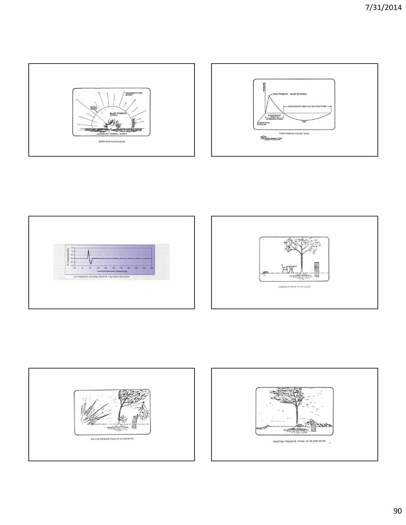
Comparison of Energy Storing DevicesWhy use explosives?
• Powerful• Fast• Compact • Self-contained• Cost effective
• Adequately accurate
• Simple• Sturdy• Reliable• Versatile
• Usable once
Comparison of energy releasing processes
MATERIAL PRESSURE(atmospheres)
RATE (g/sec)
POWER DENSITY (watt/cc)
AcetyleneFlame
1 1 100
Propellant inGun
2,000 1,000 1,000,000
DetonatingHigh Explosive
400,000 1,000,000 10,000,000,000
From W.C. Davis
Comparison of Power and Energy for Various Fuels and Storage Means
7/31/2014
90
7/31/2014
91
DETONATIONBurning and Detonation
Detonating Explosive
DETONATION
• Initiating Detonation
• Burning to Detonation (Milliseconds to Minutes)
• Shock to Detonation (Microseconds)
Partition of Energy
• Propellants
• Detonation in Air
• Confined Detonations
• Measuring the Partition of Energy
7/31/2014
92
Detonation Velocity & Pressure
• Effect of Density of Loading ( )
• Effect of Confinement (charge diameter)
• Effect of Detonator Strength
211415
21 105.3 scmgDD
Detonation Velocity ofCommercial Explosives
Type Density g cm-3
Detonation Velocity m s-1
Remarks
Blasting gelatin (92% NG) 1.55 7900 Initiated with No. 8 detonator
Polar ammonium gelatin dynamite (50% NG)
1.5 6850
Gelignite (26% NG) 1.45 6400
Plaster gelatin 1.5 6300
TNT powder (18% TNT) 1.1 4850
Water-based slurries 1.4 to 1.7 3000 to 4500 Depends on composition and diameter
ANFO 0.8 2000 to 3000 Depends on diameter
Permitted powder explosive (10% NG, 12% sodium chloride)
0.7 1800 to 2000
Detonation Parameters ofMilitary Explosives
Type D, m s-1 At D g cm-3 r Kilobar (calculated)
Secondary explosives:
HMX 9110 1.89 392
RDX 8440 1.70 300
RDX/TNT 60/40 7900 1.72 268
DATB 7520 1.79 253
Nitroglycol 8100 1.50 246
Nitroglycerine 7700 1.60 237
Tetryl 7160 1.50 192
TNT 6950 1.57 190
Primary explosives:
Lead azide 4500 3.8 192
Mercury fulminate 4500 3.3 167
Lead Styphnate 4900 2.6 157
Chapman-Jouguet Condition
wCD
D’Autriche Apparatus VOD Measurement – Resistance Method
7/31/2014
93
Voltage vs. Time
, = 2 − 1 , = 4 − 3
Four and More Resistors
Detonation Pressure
1227105.2 gscmbarDSHAPED CHARGE
SHOCK WAVE SHAPING
Damage Capacity - 2 Effects Shock Wave inCylindrical Charge
• Cooling prevents plane wave• Constant convex
7/31/2014
94
Internal Shaping: Plane Interface Internal Shaping atCurved Interface –Explosive Lens
High-to-Low orLow-to-High TransitionTo Produce Planar Wave
Implosion DeviceNuclear Fission Bomb
Explosive-Metal Wave ShaperAir Lens
CORED CHARGEAPPROXIMATELY PLANAR
7/31/2014
95
SurfaceWaveShaping
Detonation Wave fromCylindrical Charge
Shock Wave fromPlane-Ended Charge
Shock Wave fromHemispherical End, Wedge
SHAPEDCHARGE
Hollow Charge
7/31/2014
96
Liner AccelerationUses for Shaped Charge
Slow-Motion Shaped Charge PENETRATION
• Proportional to
• M is mass of jet• v is speed of jet, very great• A is cross-sectional area of jet, very small
Variables Affecting Shaped Charge Use
• Detonation parameters of the explosive• Ratio of charge length to cone diameter CD• Ratio of stand-off to CD• Ratio of liner thickness to CD• Liner geometry• Symmetry• Liner material• Fuzing mechanism (for a missile)• Effect of spin (for a gun projectile)• Cost effectiveness
Depleted Uranium Liner
• Non radioactive• Byproduct of enrichment• Heavy, 1.7 times density of lead, more like gold & tungsten; heaviness
enhances kinetic energy• Low melting point, 1132 deg C, half that of tungsten; facilitates jet
control• Pyrophoric – burns in air – hot!
7/31/2014
97
Shaped Charge Perforating Gun
Underwater Shaped Charge Linear Cutting Charge
Shaped Charge andExplosively Formed Projectile
Fragmentation Munitions
• Antipersonnel: small• Anti-vehicle: 5-10 grams• Ratio charge weight/case weight• Increase velocity, thin cloud of fragments• Need more than 1000 m/s to penetrate 10 mm steel
7/31/2014
98
Scabbing (Spalling)EMP Warhead
Explosive-driven, magnetic-flux compression generator
Flux Compression Energy Storage
Flux Generation Coil with Copper Tube
7/31/2014
99
Details of Tube Explosive Compression
Peak B-Field
Impedance Mismatch Concepts
Hugoniot EquationsHugoniot Equations Used to Determine Pressure and Particle Velocity by Analyzing Impedance (Z)
• Z = p where = Material Density, p = Particle Velocity
• Impedance Miss Matching techniques Show Trends in Pressure Conditions (Jump Conditions) at Material Interface
• Impedance Miss Matching Only Shows Jump Conditions and Does Not Take into Account Damping of Materials
Impedance Matching Pressure Developed for Rankine-Hugoniot
• Rayleigh Line Describes a Line where Momentum is Conserved which Joins the Initial to the Final States on the P- Hugoniot Jump Considerations
• Hugoniot Curve is Defined by Rankine-Hugoniot Shock Relations and Equation of State
– It Defines All Possible Shocked States a Given Material Could Achieve by a Variety of Shock Pressure
Specific Volume (1/) V
Pres
sure Rayleigh Line
Hugoniot Curve(Jump Conditions)
V2, P2
Us
1
Mat
Mat
1 = 2
1 = 2
Hugoniot is Found Empirically
Interface
P0PS
PPS0
sCP sC Velocity Shock
Impedance Z Z P
constants material Cdensity materialvelocity particle
velocity shockpressureP
1s
0
P
s
(Jump Condition Occurs From Material to Material )
V1, P1
7/31/2014
100
Procedure of Impedance Matching Used to Investigate Jump Conditions at Material Interface• Rayleigh Lines: Shock Wave Path (1-2-3-4) from Detonating HE′ to Plastic (P) to Metal (M) to Plastic to HE
• Assumed Impedance Situation:• Metal = Iron, Plastic = Teflon, HE = PBX (ZM > ZP > ZHE)
HE′
HE
P
M ZM > ZP > ZHE
HE′ P M P HE
P
1
2
34
1 2 3 4
Particle Velocity (P)
Pres
sure
(P)
U-u Hugoniot Values for Inert Materials
U-u Hugoniot Values for Inert Explosives
1. What Particle Velocity Would be Generated in the Two Materials at the Impact Interface?2. What Shock Pressure Would be Generated?3. How Fast Would the Shock be Traveling in each Material?
Look up Shock Parameter for Both Aluminum (Al) and Steel (St)2024 Al: 0 = 2.785, C0 = 5.328, s = 1.338304 St: 0 = 7.896, C0 = 4.569, s = 1.490
The Impact Will Form a Right-Going Shock in Steel whose P- Hugoniot is:
The Impact Will also Form a Left-Going Shock in the Aluminum, whose P- Hugoniot is:
Example Problem
22
2000
11.765 36.077 490.1896.7 569.4896.7s C P
2
2001000
8.1328.1785.28.1328.52.785
s C P
1.8 km/sAluminum(2024)plate
Example Calculation Continued
• Equate both Equations Equal to Each Other
2
2
2
2
69.311.2864.3869.328.1395.1183.1426.69
6.324.3 69.383.1469.268.1 8.1 69.383.1469.26
8.1 69.3 8.1 14.83
07.82
64.3807.841.641.64
equation) (quadratic a2
ac4bb
07.81.6464.3869.311.2864.38765.1136.077
2
2
2
22
Example Calculation (cont’d)
km/s 0.561 16.14-9.07- ""
14.1617.731.64
14.16124741081.64
The Pressure Equals:
Compute the Particle Velocity for Steel
GPa 243.7020.23
561.0765.11561.0077.36
765.11077.36P2
2
2
2
2
11.76536.07742 0 765.11077.36 24.0
765.11077.36P
a = -8.07, b = -64.1, c = 38.64
7/31/2014
101
Example Problem (cont’d)
km/s 56.0
"" 23.4
49.236.077-
765.11224765.1145.1301077.36
steel
Compute Particle Velocity for Aluminum:
km/s 01.7 "" 45.7
0.24253.28
equation) (quadratic 726.32
78.14720.34798253.28
726.3253.2878.14 0726.3253.28782.3824
726.3253.28782.38 P
2
2
2
a = 11.765, b = 36.077, c = -24
a = 3.726, b = 28.253, c = 14.78
Graphical Solution• Steel:
• Aluminum:
2765.11077.36P
23.726 252.28782.38P
P (Gpa)020.947.880.5119.1
p (km/s)00.51.01.52.0
P (GPa)38.725.514.14.78
p (km/s)00.51.01.5
Graphical Solution
.05 1.0 1.5 2.026
1014182226303438424650
INTERCEPT POINT
Aluminum
Steel
Particle Velocity (km/s)
Pres
sure
(GPa
)
Problem (Explosive Impact) A polyethylene flyer, 5 mm thick, traveling at 2.5 km/s impacts a thick slab of PBX9404-03
explosive. What shock pressure wave will be driven into the explosive and what is the initial time
duration ? Step 1: Find the U- Hugoniot Relationships for both these materials.
In order to find P1 at the impact interface, we need to equate the left-going wave Hugoniot in the flyer to the right-going wave Hugoniot in the target.
2.48 skm/s, 45.2C ,84.1:039404PBX1.481 skm/s, 901.2C ,915.0:nePolyethyle
00
00
Explosive Flyer Plate
2.5 km/s
5 mm
Class Problem
• A aluminum flyer plate is 8mm thick, it is traveling at 4.5 km/s and it impacts a slab of octol explosive
• What is the pressure shock wave that will be driven into the explosive and what is the initial time duration?
Step 1: Find the U- Hugoniot Relationships for both these materials
In order to find the Pressure P1 at the impact interface, we need to equate the left-going wave Hugoniot in the flyer to the right-going wave Hugoniot in the target
Octol Explosive Aluminum
4.5 km/s
8 mm
72.1 s,01.3C ,80.1:Octol1.338 s,328.5C ,785.2:)2034( umminAlu
00
00
Class Problem Initial Properties of Materials
Compute the Particle Velocity in the Oncoming Shock in the Aluminum before it Impacts the Interface
489.1 s,940.3C ,930.8:Copper1.420 skm/s, 041.5C ,833.2: umminAlu T921
00
00
AL C
Compute Pressure onShock Interface
P = 25 GPa
Plates in Contact

7/31/2014
102
Critical Energy Values and Results from NOL SSGT for Some Selected Explosives• Test Derived Critical Energy Criteria for Source Selected Explosives
• If the Calculated Critical Energy is Greater than Ec, a Detonation Will Occur in the Explosive
U-u Hugoniot Values for Inert Materials
Cooper W. Paul, Explosive Engineering,
Wiley-VCH Publishers, 1996
Rinehart, J.S., Stress Transients in Solids, Hyper Dynamics Publishers, 1975
References
Rock Blasting
Avalanche Control
• Explode charge in snow (cannon) – water• Explode on surface (flying saucer) – crater• Explode above surface – shock wave spreads out over
large area• Gondola story
Steel Cable (Wire Rope)and Closed Spelter Socket

7/31/2014
103
Swaging Process Swaging with Det Cord
Explosively SwagedCross Sections
High Energy Rate Forming(HERF) has advantages over…
Spelter Method
• Unlay cable strands and wires• Insert into spelter socket• Pour in molten metal• Fills & bonds• Zinc, 850 degrees Fahrenheit• No heavy equipment. Quick.• Heat hazardous, awkward• Zinc is a hazard
Explosive Welding of Metals
Pal Dinesh Kumar
7/31/2014
104
What Is Explosive Working Of Metals
Plastic deformations can result in shaping, joining, breaking/fracture, compaction, strengthening operations and one or many of such results are required by engineers and designers engaged in different fields.
The Mechanical working of metals which is a result of plastic deformation of metals under action of externally applied force of explosives is called explosive working of metals.
History of Explosive Working
• Gun Powder – 1000 AD – China
• Fragmenting Bomb – 1400 AD
• Grenades – 1900 AD
• Shaped charge – 1894 AD - Munroe• Between Ist and IInd World War (Fragmenting shells, Hollow Charge Warheads)
• Explosive Welding – 1964 by Dupont
• Explosive Forming – 1960 onwards
This technology was developed in the decades after the World WarII, which get originated however back in the World War I, when thepiece of Shrapnel sticking to armour plating were observed andfound that not only it get embedding themselves but were actuallybeing welded to the metal
However, explosion welding can join nearly every kind of metaltogether. In fact, more than 260 metal combinations are possible.In today’s industries, around 80% of the world’s EXW productionis clad plates, primarily used in the process industries for corrosionor wear resistant equipment
The characteristics of good welding requires that the strength ofthe weld should be as strong as the weaker of the two componentmaterials
Figure 5. Simon stevin
Brief history
Brief history
Process: Explosive welding is used for largesurface area joining of dissimilar materials
- two metal plates are impacted together(oblique collision) by using the detonationpressure of explosive to join at theinterface.
- The high velocity impact leads to a veryhigh pressure at the interface leading toformation of a jet, which effaces metalsurfaces and brings them into sufficientlyclose contact, to form a solid-statemetallurgical bonding.
- Materials having large differences in theirproperties can be easily be joined withoutany initial capital investment.
- Any material can joined, provided thematerial maintains its integrity during theprocess. The process can be carried out intwo types of setup, inclined or parallel.
Explosive Welding ProcessExplosive Welding Process

7/31/2014
105
EXPLOSIVE WELDING
ADVANTAGE APPLICATIONLIMITATION
• Solid state bond.• Area bond.• Minimum fixture/ jig required.• No Heat Affected Zone, as melting does not takes places.• There is no effect on the parent metal property.• Can join large plate in a very short time.• High uniform mechanical bond strength
• Noise and vibration are generated during the process.• Storage of explosive is also very big problem because explosive can ignite by chance.• The metal must have enough impact resistance and ductility.• It is not suitable for brittle material, as they should be some ductility in material.
• Used by the marine for thevarious applications for thestructurally sound corrosionresistant of aluminum and steel(Mckenney & Banker).• Cylindrical components such astubular transition joints, tube totube plate and concentric cylinders(Addison et al)• Heat exchanger with a clad tubesheet and sheet (Buijs).•Joining of similar and dissimilarmaterials.
There are many factors which affect the phenomenon process i.e. the jetformation, collision angle, stand-off distance, velocity of detonation used.
Jet Formation
It is one of the phenomenon that occurs during the weldformation, the collision angle determine the formation ofthe jet. For the waves formation jet is responsible. Thejet formation range is between 40 and 150 of the initialangles, and that of the quality of the weld was foundbetter at 100 (Grignon et al, 2004)
The collision angle (β)
It determines the formation of the jet. The change in theinterface morphology in the welded front from wavy tosmooth is directly due to the change in the collisionangle (Grignon, 2004)
Fig 2. JET Phenomenon
Important Parameters
Stand-off distance.
It plays an important role as it is the one which helpsin metal acceleration and obtain the desire angle forweld. Stand-off distance that is twice the flyer platethickness is used for thin component (up to 6.5mm or0.26in.) and for the thicker components (up to 13mm,or 0.5in) the stand-off distance is equal to the flyerplate thickness (Wolf, 1988).
Fig 3. Stand off Placed b/w Plates
Velocity of detonation (V.O.D)
Detonation is a process in which the explosiveundergoes chemical reactions at a considerably highspeed and produces a shock wave also called adetonation wave. High temperature and pressuregradients are generated in the wave front so that thechemical reaction is initiated instantaneously.
Fig 4. Detonation of Explosive
An important material characteristic for material bonding is material ductility
Clad ability of material can be improved by annealing/stress relieving, whichlowers the tensile strength and UTS and improves ductility of the material(Montgomery, 2004)
Jet formation at the collision point is an essential condition for welding. Thejet if formed sweeps away the oxide layers on the surface of the metals leavingbehind clean faces which are more likely to form a metallurgical bond bymaking it possible for the atoms of two materials to meet at inter atomicdistances when subjected to the explosively produced pressure waves.
The pressure has to be sufficiently high and for a sufficient length of time toachieve inter-atomic bonds
Summary of literature review
The quality of the bond depends on careful control of process parameterssuch as surface preparation, plate separation, detonation energy anddetonation velocity Vd. While various welding mechanisms have been proposedfor the explosive welding, they all almost agree that it occurs as a direct resultof high velocity oblique collision
A sufficient stand-off distance has to be provided in order to flyer plate canaccelerate to the required impact velocity
For a given metal, β is a function of the collision velocity. The collisionvelocity Vc and the plate velocity Vp must be less than the velocity of soundin either metal (Walsh, 1953).
Figure 6 Wave Formation
1. Calculation of minimum flyer plate velocity based on hardness
where, H : Diamond penetration hardness,k1 : Surface finish coefficient, 0.6 for high quality surface
1.2 for low quality surface finish
Vpmin based on hardness is obtained by taking highest of the two values for the base plate and the flyer plate.
2. Collision point velocity determination
where, RT : Reynolds number f, b : subscript refers to the flyer plate and base plate.
3. Maximum flyer plate velocity determination
N: 0.11 (in cgs units) ,Tmp: Melting Point ,Cb: Bulk Sound VelocityK : Thermal conductivityC : Specific Heath : Thickness of flyer plate
4.Flyer plate velocity
Calculations
7/31/2014
106
5. Determining the weight and thickness of the explosive
After obtaining the value of R, the value of C can be found.
6. Calculation of temperature into the standoffBoltzmann`s equation,
where, Rg = universal gas constant = 8.31, µ = 0.029 (molar mass of air)
for example, if Vc is 2096 m/s, then
Explosive Window
Copper and MS Plate Joining
Various test to check out the mechanical characterization of the welded joint, in which we have taken Ram tensile fixture to evaluate the strength of the welded material
Auto cad 3D view and Auto cad 2D view
Tool Ram Tool base blockRam Tensile fixture
Ram Tensile Test
Figure 7 Receiving plates
Figure 8 Plate cleaning, finishing
Figure 9 Placing Stand-off welding
Figure 10 explosive welding in underground
Figure 11 wider plates are flattened using a 1500 ton press
Figure 12 Bend Removable by rolling
Figure 13 Plate cutting to final size.
Figure 14 Ultrasonic inspection
Figure 15 Plate ready for dispatch
Explosive Welding Production Automation

7/31/2014
107
This process is most commonly utilized to cladcarbon steel plate with a thin layer of corrosionresistant material (e.g., stainless steel, nickel alloy,titanium or zirconium).
Anti-CorrosionProducts
Al-SS Tube Carbon Steel-SS Plate Carbon Steel-SS PlateIn Naval structure
Explosively Welding/Cladding Pipe Joints
Heat Exchanger by Explosively Welding
Titanium-Steel Clad Plate for Tube Sheet
Tube Sheet made from clad plate
Heat Exchanger by Explosively Welding
Explosively Formed Heat-Exchanger
Arrangement for Trial
Explosively Formed Heat-Exchanger
Arrangement for Trial
Explosively Welded/Cladded Transition Joints
Copper/Stainless 12″ UHV Assembly
12″Dia Copper/Steel Transition Joints
3″ Diameter Al/SS Ring
12″ Diameter Al/SS Ring
Electrical Transition Joints of Aluminum/Steel
Structural transition joint (STJ) bars are sawed from large plates
Products made by Explosive Welding
Ni-alloy /Steel Sheet Clad Metal
Al-alloy/Steel Electrical Transition Joint
Al-alloy/Stainless Steel Electrical Anode Inserts
Copper /Stainless Steel Bar Clad Metal
Copper /Stainless Steel Bar Clad Metal Rolled to Ring
US Government chooses X-Clad for new coinage
7/31/2014
108
Deployed on US Navy Aircraft Carriers
Aluminium Tube/Steel Billet
Explosive Welded Large Plates
Explosive Welded Current Conducting Arms (CCA) for Electric Arc Furnace
Products made by Explosive Welding
Aluminium Pipe
Copper/Stainless Steel Slit for UHV Beam
Line
Copper/Stainless Steel UHV Conflate Flange
SS / Cu/ SS 6″ Custom Conflate Flange
Explosive Welded Copper/Stainless
Steel
SS Rib
Transition Bar
Al Rib
SS Pipe
Titanium/316L steeltube with a couplingof 321L steel
Products made by Explosive Welding
Pioneers of Explosive Working of Metals• Dr John Rhinehart• Dr Prof B. Crossland• Dr AA Deribas• Rolf Prummer• Lawrence E. Murr• Prof. Meyers• Dr Prof Manfred Held
PropellantsBurningGunsGun PropellantsRocket Propellants
BURNING
• All explosives burn• Burning can occur when confined• Burning at or just above the surface• Surface itself recedes layer by layer (Piobert’s Law,
1839)• Traité d'artillerie Théorique et Pratique by Guillaume
Piobert (1845)
BURNING
•Heat radiated from reaction zone
•Heat conducted from reaction zone
•Heat from decomposition
7/31/2014
109
Rate of Regression
•Burning Rate Index •Mass Rate of Burning•A Surface Phenomenon
Pr
GUNS• Interior Ballistics, 3rd Edition. James M. Ingalls. John
Wiley & Sons, New York. 1912.• Elements of Ordnance. Thomas J. Hayes. John Wiley &
Sons, New York. 1938.• The Machine Gun. Design Analysis of Automatic Firing
Mechanisms and Related Components. George M. Chinn. Volume IV, Parts X and XI. Bureau of Ordnance, Department of the Navy. 1955.
French 75 Long Recoil System
Spring-Loaded Magazine Positions Cartridge in Front of Bolt
Typical Gun PropellantGrain Geometry
7/31/2014
110
Properties Required in a Propellant
• An acceptable high energy/bulk ratio.• A predictable burning rate over a wide range of pressures.• An acceptably low flame temperature.• A capability of being easily and rapidly ignited.• An acceptably low sensitiveness to all other possible causes of initiation.• A capability of cheap, easy and rapid manufacture and blending.• A long shelf life under all environmental conditions.• A minimum tendency to produce flash or smoke.• A minimum tendency to produce toxic fumes.
Rate of BurningGuillaume Piobert (1839)
Vieille’s Burning Rate Law (1893)
• Rate of burning (mm s-1) is r.• Burning rate coefficient is .• Pressure is P• Pressure index is .
Pr Paul Vieille (1854-1934)
Solid Form –Spheres, Plates, Cylinders
•Decrease in surface area during burning•Degressive burning•Decrease in dm/dt with time (at a theoretical constant pressure)
Single-Perforated Form
• Inner surface area increases• Outer surface area decreases• Burning area approximately constant• Neutral burning characteristic• Constant dm/dt (at theoretical constant P)
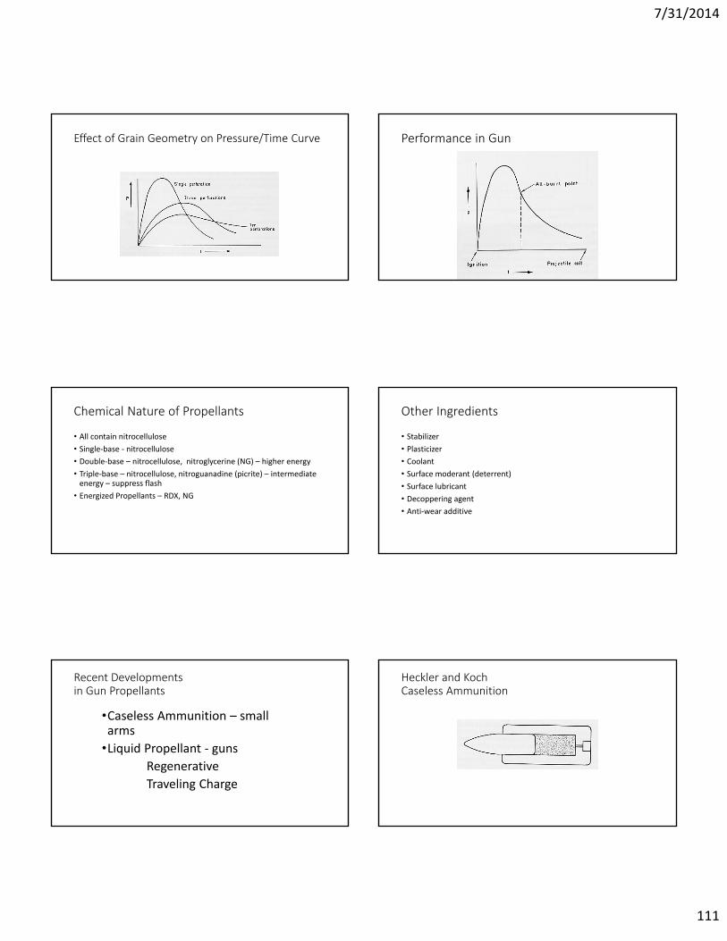
7/31/2014
111
Effect of Grain Geometry on Pressure/Time Curve Performance in Gun
Chemical Nature of Propellants
• All contain nitrocellulose• Single-base - nitrocellulose• Double-base – nitrocellulose, nitroglycerine (NG) – higher energy• Triple-base – nitrocellulose, nitroguanadine (picrite) – intermediate
energy – suppress flash• Energized Propellants – RDX, NG
Other Ingredients
• Stabilizer• Plasticizer• Coolant• Surface moderant (deterrent)• Surface lubricant• Decoppering agent• Anti-wear additive
Recent Developmentsin Gun Propellants
•Caseless Ammunition – small arms
•Liquid Propellant - gunsRegenerative Traveling Charge
Heckler and KochCaseless Ammunition
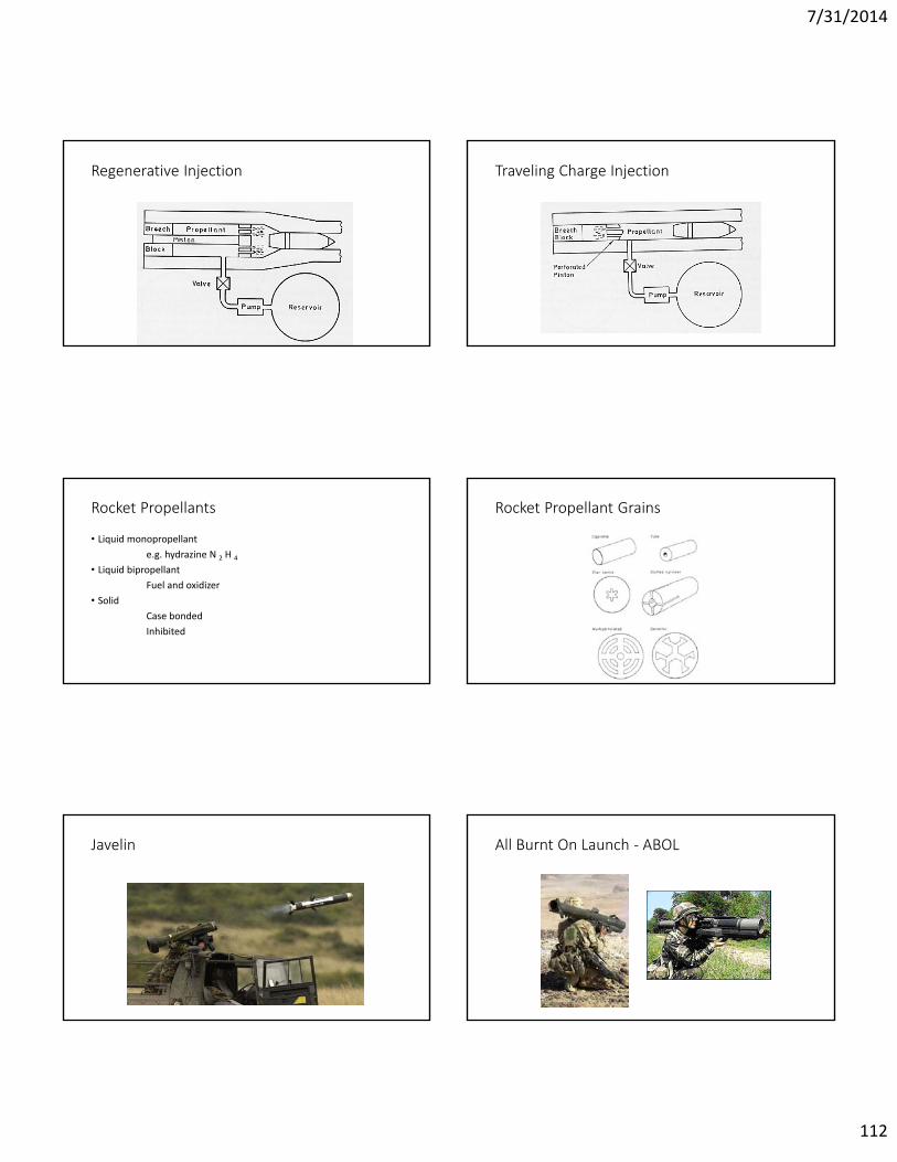
7/31/2014
112
Regenerative Injection Traveling Charge Injection
Rocket Propellants
• Liquid monopropellante.g. hydrazine N 2 H 4
• Liquid bipropellantFuel and oxidizer
• SolidCase bondedInhibited
Rocket Propellant Grains
Javelin All Burnt On Launch - ABOL
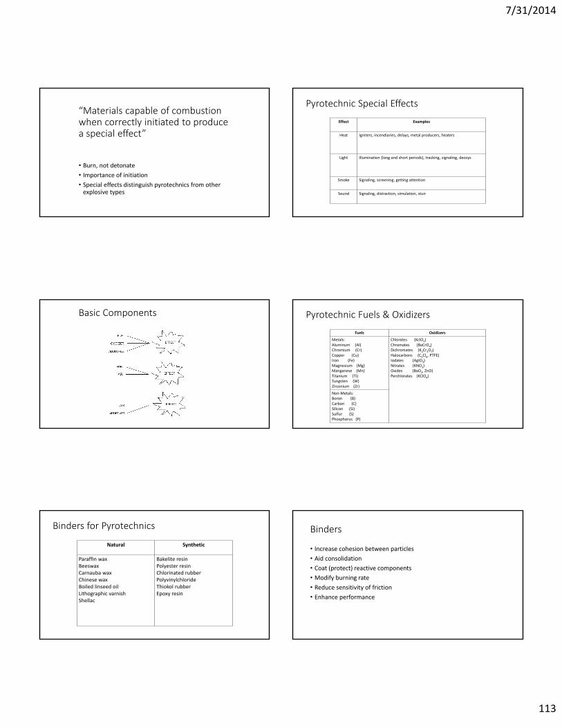
7/31/2014
113
“Materials capable of combustion when correctly initiated to producea special effect”
• Burn, not detonate• Importance of initiation• Special effects distinguish pyrotechnics from other
explosive types
Pyrotechnic Special Effects
Effect Examples
Heat Igniters, incendiaries, delays, metal producers, heaters
Light Illumination (long and short periods), tracking, signaling, decoys
Smoke Signaling, screening, getting attention
Sound Signaling, distraction, simulation, stun
Basic Components Pyrotechnic Fuels & Oxidizers
Fuels OxidizersMetals:Aluminum (Al)Chromium (Cr)Copper (Cu)Iron (Fe)Magnesium (Mg)Manganese (Mn)Titanium (Ti)Tungsten (W)Zirconium (Zr)
Chlorates (KclO3)Chromates (BaCrO4)Dichromates (K2Cr2O7)Halocarbons (C2Cl6, PTFE)Iodates (AgIO3)Nitrates (KNO3)Oxides (BaO2, ZnO)Perchlorates (KClO4)
Non-Metals:Boron (B)Carbon (C)Silicon (Si)Sulfur (S)Phosphorus (P)
Binders for Pyrotechnics
Natural Synthetic
Paraffin waxBeeswaxCarnauba waxChinese waxBoiled linseed oilLithographic varnishShellac
Bakelite resinPolyester resinChlorinated rubberPolyvinylchlorideThiokol rubberEpoxy resin
Binders
• Increase cohesion between particles• Aid consolidation• Coat (protect) reactive components• Modify burning rate• Reduce sensitivity of friction• Enhance performance
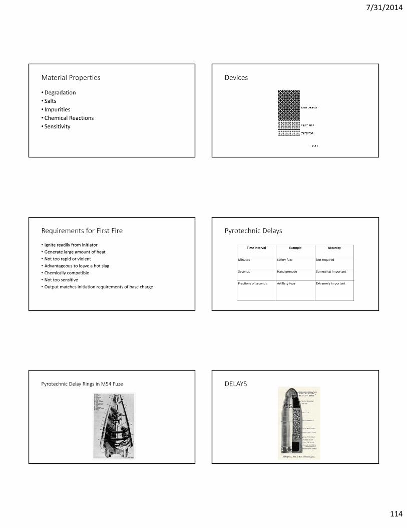
7/31/2014
114
Material Properties
• Degradation• Salts• Impurities• Chemical Reactions• Sensitivity
Devices
Requirements for First Fire
• Ignite readily from initiator• Generate large amount of heat• Not too rapid or violent• Advantageous to leave a hot slag• Chemically compatible• Not too sensitive• Output matches initiation requirements of base charge
Time Interval Example Accuracy
Minutes Safety fuze Not required
Seconds Hand grenade Somewhat important
Fractions of seconds Artillery fuze Extremely important
Pyrotechnic Delays
Pyrotechnic Delay Rings in M54 Fuze DELAYS
7/31/2014
115
Henry Shrapnel Time-Delay Grenades
Pyrotechnics Heat Produced
Fuel Heat of Combustion orHeat of Reaction with Oxygen, kJ g-1
Aluminum (metal) 40.7
Iron (metal) 9.2
Tungsten (metal) 5.7
Barium (metalloid) 57.8
Sulfur (non-metal) 9.3
FRH and MRE Example of Thermite Reaction
2 Al + Fe2 O 3 → Al2 O 3 + 2 Fe
7/31/2014
116
Pipe Recovery Thermite Initiator
Thermite Cutting Tool AN-M14 TH3Incendiary Grenade
Hans Goldschmidt Disadvantages of Thermite Reactions
• Difficult to Start (magnesium, glycerin/potassium permanganate)
• Must Be White Hot• Extremely High Temperatures• Keep Flammables Away!• Boiling Metals
7/31/2014
117
Thermal Battery Pyrotechnic Whistle
Entschede – May 2000Testing Explosives
Output TestsInput (Sensitivity) Tests
Ballistic Pendulum Input (Sensitivity) Tests
•Quantal Response•Important to know exactly how sensitive•Powder tests (mfg and filling)•Charge Tests

7/31/2014
118
Ball Drop Apparatus Bureau of MinesBall-Drop Apparatus
Die Cup Drop Tester for Powder
Friction Test Apparatus Sliding Block Friction Apparatus
7/31/2014
119
Diagram ofFriction Pendulum Apparatus BAM Friction Tester
High Voltage Spark TesterLarge Scale ESD TesterSTANAG 4490, Mil-Std-1751A
SMALL SCALE ESD TESTERSTANAG 4490, MIL-STD-1751A Nylon Washer Dimensions
Dimension Inch mm
Thickness minimum 0.035 0.88
Thickness maximum 0.063 1.60
Inner diameter minimum 0.13 3.30
Inner diameter maximum 0.16 4.06
7/31/2014
120
Sample Preparation Bullet Impact Test
Electroexplosives:Functioning, Reliability and Hazards
Accident PreventionPresented by Franklin Applied Physics, Inc.
• All commercial explosive materials are designed to detonate when supplied with a sufficient amount of initiating energy. Unfortunately, the explosive material cannot differentiate between inintiating energy purposely supplied and that accidaentally supplied. It is the responsibility of all persons who handle explosive materials to know and to follow all approved safety procedures.
• --from IME Do’s and Don’ts
Some causes of unintended initiation
• Fire • High temperature• Thunderstorms• Electromagnetic fields• Sparks• Static electricity• Current and voltage sources• Impact• HUMAN ERROR
Fire prevention
• Good housekeeping• Avoid storing combustibles (paper, rags)• Avoid storing fuels• No smoking or open flames (heaters, burners, lighters)• Maintain electrical equipment and cords• Care with sources of heat• Fire extinguishers readily available (only to prevent spread to area near
explosives)

7/31/2014
121
Thunderstorms
• Monitor weather conditions• Storm monitoring equipment or AM radio • 5 miles approach• Shut down operations and evacuate• Use single ground point for EED systems
Electromagnetic fields
• Twist and coil leadwires (small aperture)• Stay away from transmitters (even small ones like cell phones)• Use RF protected devices (with ferrites, coils, capacitors) – not all
frequencies• Perform worst-case analysis and field tests before use
Spark Prevention
• Use non-sparking tools (wood, bronze, lead, "K" Monel)• Avoid metal work surfaces, floors, etc.• Well-maintained equipment• Some electric motors produce sparks• No flash bulbs or electronic flash• Prevent static electric sparks
Static electricity prevention
• Ground everything (and check frequently)• Avoid plastics• Avoid contact and separation processes• High humidity – above 55%• Non-static equipment & environment• Proper clothing• Use verified static-insensitive EEDs
Current sources
• Use only approved meters to measure resistance (less than 1 mA, or 10μA for carbon bridge)
• Consider all modes of initiation• AC sources• Batteries• Ground currents• Galvanic current

7/31/2014
122
Human Error
• Educate all workers• Always follow standard operating procedures exactly• Do not take shortcuts• Do not improvise• Know characteristics of what you are working with• Don’t assume one type of device can be handled the same as another type• Know what to do in an emergency
Reckless Way to Open a Powder Keg
Miner with Torch on HatPouring Black Powder
Hazard Avoidance
•Mechanical shock•Heat
Electric WeldingHazards to EEDs
• Fire• Electromagnetic Radiation• Magnetic Field Coupling• Ground Currents
Circuit with Grounds
7/31/2014
123
Electric Welding Near Well Recommendation
• Maintain 50-foot (15 meter) standoff distance.
AC Overhead Power Line
•Hazard to power line
•Hazard to blaster from electric shock
Non-Hazards
•Electromagnetic effects from AC power line
•EMP•Radioactivity
Non-Hazards
•Modern digital camera with automatic focus and built-in flash (but be careful of batteries)
Storage and Shipment•Receiving•Storage•Use•Shipment•Disposal

7/31/2014
124
US Naval Ammunition DepotEast Camden, Arkansas
PEOPLE WHO CAN RECEIVE AND SHIP EXPLOSIVES
•“Responsible Person” – on license application
•“Employee Possessor” –separate application
Receiving Paperwork
• Log book• Unpack, saving materials
(photo)• Count• Box tag• Transaction log• Receiving report
• Waybill• EX letter• MSDS• Box card
Storage Paperwork
• Daily transaction summary• Update box card• Check locks weekly
Use Paperwork
•Magazine transaction log
Shipping Paperwork
• Log book• Shipping report• EX letter• Waybill• Labeling

7/31/2014
125
Magazine Requirements
• Separate magazines• Bullet-proofing• Security• Quantity-Distance• Recordkeeping• Housekeeping• License Display• Warning Sign – “Explosives: Keep Away”
Shipping ClassificationShipment• CFR 49• Proper Shipping Name, UN Number• Hazard Classification, Orange Label• 24-hour telephone number• Competent Authority, EX number• Certification – be careful what you sign!• Training every 3 years• Packaging• Vehicle Requirements – placard, inspection• Cost
IME SLP TitlesNumber Title
1 Construction Guide for Storage Magazines2 The American Table of Distances3 Suggested Code of Regulations for the Manufacture, Transportation, Storage, Sale,
possession and Use of Explosive Materials4 Warnings and Instructions for Consumers in Transporting, Storing, Handling and
Using Explosive Material12 Glossary of Commercial Explosives Industry Terms14 Handbook for the Transportation and Distribution of Explosive Materials
17 Safety in the Transportation, Storage, Handling and Use of Explosive Materials20 Safety Guide for the Prevention of Radio Frequency Radiation Hazards in the Use of
Commercial Electric Detonators (Blasting Caps)21 Destruction of Commercial Explosive Materials22 Recommendations for the Safe Transportation of Detonators in a Vehicle with Certain
Other Explosive Materials
Shipping Papers•Proper Shipping Name, Hazard Class, UNxxxx, Packing Group
(Cartridges, power device, 1.3C, UN0276, Pkg Gp II
•n.o.s (not otherwise specified)
(Substances, explosive. n.o.s., 1.1D, UN0475, Pkg Gp II,
6573.3 propellant, 5808.17 propellant, mix)
•“EX” number for explosives
•24 hr phone (3E Company 1-800-451-8346)
•Quantity
•Package type
•Certification and signature

7/31/2014
126
DOT-SP 8451 Shipping Container DOT SP-8451 Labeling
Related Reading
• Recommendations on the Transport of Dangerous Goods – Manual of Tests and Criteria. 1999. United Nations. ST/SG/AC.10/11/Rev.3.
• Institute of Makers of Explosives (IME). 1120 Nineteenth Street N.W., Suite 310, Washington, DC 20036-3605.
Disposal of life expired stocks – UK policy to return to UK everything except not safe to move
Novobogdanovka, Ukraine, 2004 Chubs for Use in Disposal

7/31/2014
127
Munition with Chubs Containment
HISTORY
759
Greek Fire
760
Congreve Rocket
761
History and Development ofMilitary Pyrotechnics• Faber, Henry B. Military Pyrotechnics. Volume
1.Ordance Department, U.S. Army. Washington, DC, U.S.A. Government Printing Office (1919)
• “The first preparation for the work of the future is a knowledge of what has already been accomplished in the past. Pyrotechny is the art of fire, and its history began long ago.”
762
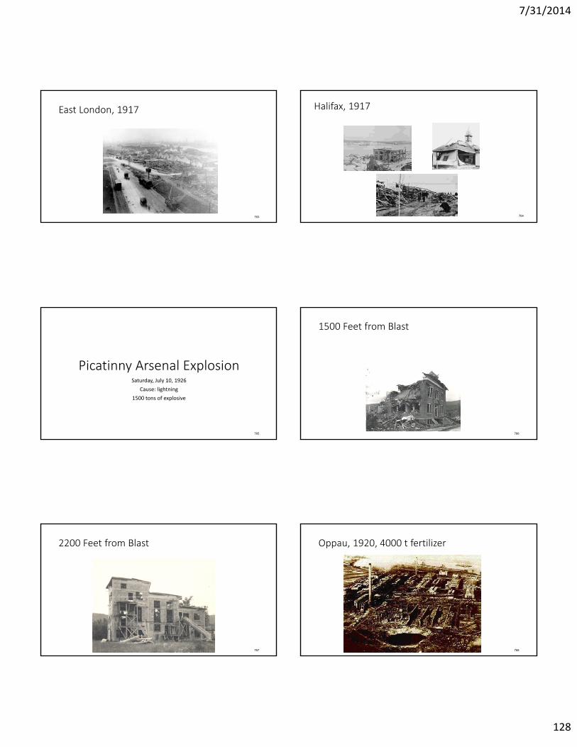
7/31/2014
128
East London, 1917
763
Halifax, 1917
764
Picatinny Arsenal ExplosionSaturday, July 10, 1926
Cause: lightning1500 tons of explosive
765
1500 Feet from Blast
766
2200 Feet from Blast
767
Oppau, 1920, 4000 t fertilizer
768

7/31/2014
129
Oppau
769
Bombay 1944
770
RAF Faulds, 1944, 3500 t
771
Blausee-Mithols, 1947, 3000 t
772
Texas City, 1947
773
Roseburg, Oregon
774
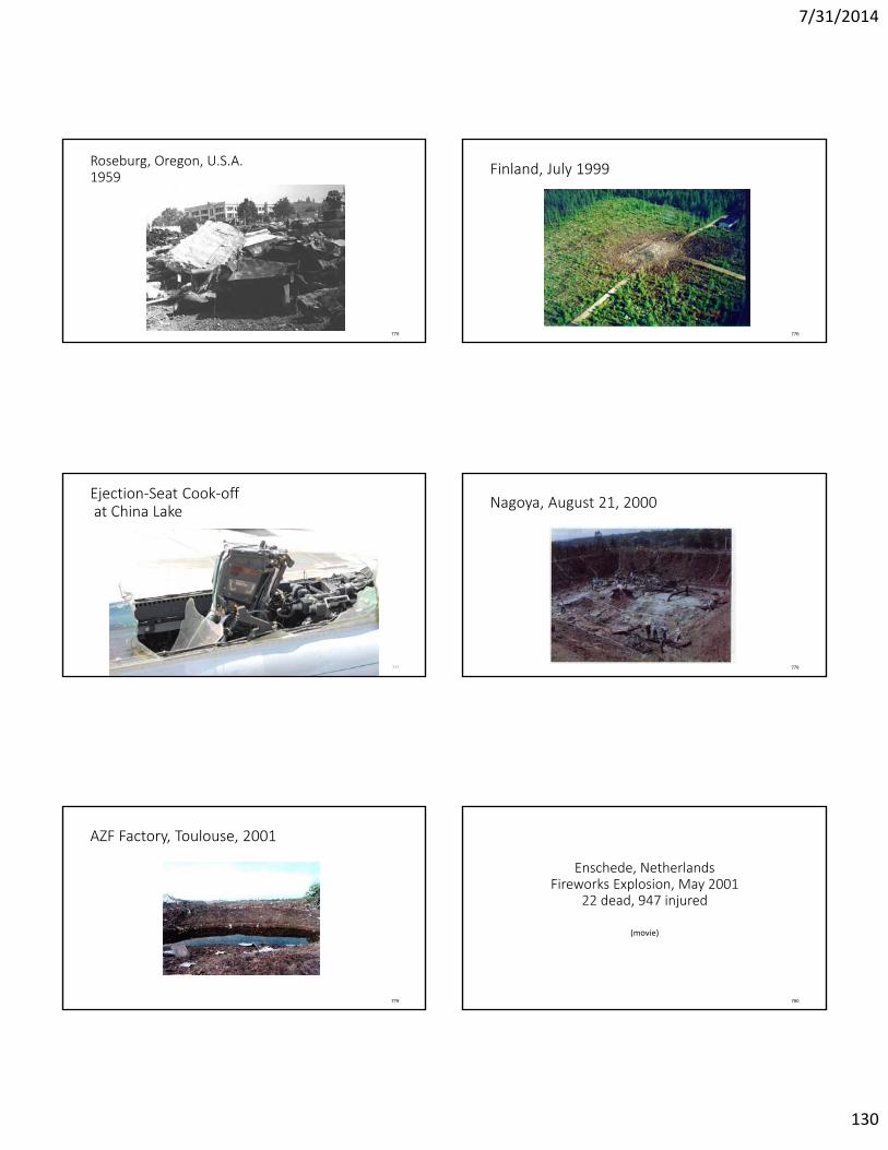
7/31/2014
130
Roseburg, Oregon, U.S.A.1959
775
Finland, July 1999
776
Ejection-Seat Cook-offat China Lake
777
Nagoya, August 21, 2000
778
AZF Factory, Toulouse, 2001
779
Enschede, NetherlandsFireworks Explosion, May 2001
22 dead, 947 injured
(movie)
780

7/31/2014
131
Saint Barbara –Sigfrido Martín Begué, 2003
781
Martyrdom of St. Barbara
782
RESOURCESSources of Information
InspirationEncouragement
Technical ReportsTests & Analyses
•Franklin Applied Physics, Inc. (1960 to present), www.franklinphysics.com
•National Technical Information Service (NTIS), www.ntis.gov
Newsletters, Journals I.S.E.E.

7/31/2014
132
SYMPOSIA
• CAD/PAD TEW – NSWC Indian Head, May even years, Maryland, free
• Disposal Conference – Swedish Combustion Institute, November odd years, in a castle
• DoDESB – US Government, August, in a hot place
More Symposia
• Energetic Materials – Fraunhofer Institute for Chemichal Technology (ICT), June, Karlsruhe, Germany
• Commercial Explosives, Blasting – International Society of Explosives Engineers (I.S.E.E.), February, USA
• HEMCE – India, November odd years
MORE SYMPOSIA
• International Pyrotechnic Seminar / Society (IPS), June, alternates between Colorado USA and elsewhere in the world
• NTREM – Univ. Pardubice, April, Czech Republic, students and young researchers
Proceedings, Printed, CD-ROM
ENCYCLOPEDIA Bonnie & Ken Kosanke
7/31/2014
133
AMC HANDBOOKS AMC-R 385-100 Safety Manual
DOD 4145 . 26 - M DOE M 440.1 - 1

7/31/2014
134
DoD 6055.9 - STD Engineering Standards
BOOKS
G. S. Biasutti, History of Accidents in the Explosives Industry• Wrong design or wrong construction of machines leading to
mechanical or structural failures, overload: 18 accidents• Mechanical: Tapping, hitting, scraping, stumbling, use of force,
collision, presence of foreign bodies in the explosive, rough handling: 205 accidents
Biasutti, continued• Chemical: Poor mixing, lack of cooling, wrong
chemical balance leading to instability, self-decomposition: 79
• Electrical: Electric sparks, short circuits, static electricity: 18 accidents
• Thermal: Overheating, contact with hot bodies, smoking or other unauthorized presence of flame, adiabatic compression: 54 accidents

7/31/2014
135
Biasutti, continued
• Indirect: External fire, lightning: 22 accidents
G. S. Biasutti, History of Accidents in the Explosives Industry
CauseNumber of Accidents
Wrong design or wrong construction of machines leading to mechanical or structural failures, overload 18
Mechanical: Tapping, hitting, scraping, stumbling, use of force, collision, presence of foreign bodies in the explosive, rough handling 205
Chemical: Poor mixing, lack of cooling, wrong chemical balance leading to instability, self-decomposition 79
Electrical: Electric sparks, short circuits, static electricity18
Thermal: Overheating, contact with hot bodies, smoking or other unauthorized presence of flame, adiabatic compression 54
Indirect: External fire, lightning 22
CATALOGS, WEB SITES

7/31/2014
136
FORENSIC INVESTIGATION
Reference:
•“Forensic Investigation of Explosions,” edited by Alexander Beveridge
•Taylor & Francis Ltd., London (1998).
• ISBN 0-7484-0565-8.
Chapters by Many Experts• Military research establishments• National police forces• EOD (explosive ordnance disposal) units• Government aviation experts• Medical departments• Legal systems• Explosives manufacturers• Et cetera
Outline
• Basics of energetic materials – propellants and explosives
• Explosion process in detail – blast waves and their effects
• Detection of hidden explosives• How to gather evidence at the scene of an explosion –
aircraft – gas in buildings• Detailed laboratory methods to analyze chemical &
mechanical evidence
Outline -- Continued
•Medical pathology of human victims of an explosion - photographs, x-rays
•How to give evidence in a court of law


![[XLS] · Web viewLast Chance Audubon Society N53 Five Valleys Audubon Society N54 Flathead Audubon Society N55 Pintler Audubon Society N57 Upper Missouri Breaks Audubon Society N58](https://static.fdocuments.in/doc/165x107/5af10a307f8b9a8c308dfd70/xls-viewlast-chance-audubon-society-n53-five-valleys-audubon-society-n54-flathead.jpg)