
JOHN DEERE 9976 & 9986 - Weeblymudhog.weebly.com/uploads/7/3/6/2/7362507/106063_im_jd40004.pdf · -...
26
- 1 - INSTALLATION MANUAL PLUS SERVICE PARTS INFORMATION FOR Mud Hog® System III 2-Speed Rear Wheel Drive FOR JOHN DEERE 9976 & 9986 COTTON PICKERS Mud Hog® Model Numbers: Aftermarket JD47761 OEM JD40004 ® TUTHILL Drive Systems Brookston Indiana USA Revised 8/2010 P.N. 106063
Transcript of JOHN DEERE 9976 & 9986 - Weeblymudhog.weebly.com/uploads/7/3/6/2/7362507/106063_im_jd40004.pdf · -...

- 1 -
INSTALLATION MANUAL
PLUS
SERVICE PARTS INFORMATION
FOR Mud Hog® System III 2-Speed Rear Wheel Drive
FOR
JOHN DEERE
9976 & 9986 COTTON PICKERS
Mud Hog® Model Numbers:
Aftermarket JD47761 OEM JD40004
®
TUTHILL Drive Systems
Brookston Indiana USA
Revised 8/2010 P.N. 106063

General Information
CATALOGS
This parts catalog is provided to aid in the identification of Mud Hog components. It containsan illustration, part number, required quantity, and a description of each part included in the kit.
Catalogs may contain information for several different machines which use similar Mud Hogkits. The appropriate machine model and Mud Hog base model number should be selected toassure proper part identification. Each Mud Hog conversion package contains all or some ofthe following kits or subassemblies:
A - HYDRAULIC ADAPTER KIT(S)B - HYDRAULIC HOSE KITC - EQUA-TRAC II VALVE BASE ASSEMBLYD - WHEEL DRIVE BASE ASSEMBLY - RIGHT HAND & LEFT HANDE - TIE ROD EXTENSION SUBASSEMBLYF - MOUNTING KITG - WHEEL AND TIRE KITS
We reserve the right to make changes and improvements in design and specifications withoutnotice and without obligation to provide or substitute new design modifications for those MudHog systems or components already in service.
REPLACEMENT PART ORDERING AND RETURNED PARTS INFORMATION
Replacement part orders should include the complete Mud Hog part number and description,base model number of Mud Hog kit, Mud Hog Serial Number (located on the wheel motormounting frame or on the axle), machine model number, method of shipment, and shippingaddress information.
Parts returned for warranty determination should be accompanied by a Warranty Claim Formwith and RGA (Returned Goods Authorization) number. Before returning parts, contact theTuthill Transport Technologies Customer Service Department to obtain an RGA number. Anymaterial returned to Tuthill Transport Technologies without an RGA number prominentlydisplayed on the packaging and/or the returned parts, will NOT be processed and will be returnedfreight collect to the dealer. The warranty Claim Form is included in the literature package(including a Parts Catalog and Installation/Operation Manual) sent with the Mud Hog kit. Ifmissing, or if additional forms are needed, contact the Tuthill Transport Technologies CustomerService Department.
NOTE: Mud Hog and Equa-Trac are registered trademarks of Tuthill TransportTechnologies.
A

Instructions and Specifications
INTRODUCTION
This manual provides instructions for installing the Mud Hog Drive System on hydrostatic machines. Variousmachine options such as rear axle width and front tire size affect Mud Hog adaptation. These differences arespecifically referred to in these instructions. Always follow the instructions which refer to the exact optionconfiguration on the machine being converted.
A complete pictorial breakdown of all the individual parts in the Mud Hog Drive System can be found in the MudHog Parts Catalog. Refer to this catalog for proper identification of parts required for service.
GENERAL
The terms right and left in these instructions are the same as the operators right and left hand when positioned in theoperator’s seat facing forward. IMPORTANT: Cleanliness is essential when installing or servicing hydrauliccomponents. When making hydraulic connections, areas surrounding the connection should be steam cleaned orwashed with solvent so that contamination will not enter the system. Always keep hoses and connectors and portssuitably capped or covered to keep contamination out of the system. CAUTION: Make sure that system pressure isrelieved before disconnecting any lines or connections. Pressurized fluid escaping from the system can cause seriouspersonal injury.
TORQUE SPECIFICATIONS RECOMMENDED FOR USE WITH Mud Hog FASTENERSRecheck all bolt & nut torque after 1 hour’s use and again after first day of use. Periodically check tightness every100 hours of use thereafter. Note: bolts that require Loctite should not be re-tightened once Loctite has had time tocure. Note: When using original equipment fasteners, adhere to manufacturers’ recommended specifications.
GRADE 8 (GRADE 10.9 METRIC) BOLTS AND GRADE C LOCKNUTS SIZE BOLT TORQUE[1] LOCKNUT TORQUE[2](S.A.E.) (ft.lbs.) (ft.lbs.)1/4 -20 10-13 7-105/16-18 18-25 15-183/8 –16 35-45 30-357/16-14 55-70 45-551/2 -13 90-110 60-809/16-12 120-150 90-1105/8 –11 180-200 150-1703/4 -10 300-350 250-2807/8 –9 400-450 350-380M10-1.5 35-45 30-35M16-2.0 180-200 150-170M20-2.5 400-450 350-380
HYDRAULIC FITTINGS, HOSE ENDS, TUBE NUTS DASH SIZE THREAD SIZE TORQUE[3] (S.A.E.) (S.A.E.) (ft.lbs.)
-4 7/16-20 9-12-6 9/16-16 21-24-8 3/4-16 35-40-10 7/8-14 55-60-12 1 1/16-12 77-82-16 1 5/16-12 110-120
[1] Torque to be applied to Grade 8 bolts.[2] Torque to be applied to Grade C locknuts.[3] Torque to be applied to S.A.E. straight thread O-Ring Boss (ORB) fittings/locknuts and 37degree flared type (J.I.C.) fittings/hose ends and tube nuts.
NOTE: Mud Hog and Equa-Trac are registered trademarks of Tuthill Transport Technologies. B

!Safety Procedures
1) READ THESE PROCEDURES COMPLETELY. Make sure you fully understand allcontrols BEFORE operating the system.
2) The safety information given does not replace safety codes, insurance needs, or federal, state,and local laws.
3) Standard safety procedures should be observed and practiced when operating or servicing theMud Hog system. CAUTION should be practiced at all times.
4) All components MUST be securely and correctly mounted and connected BEFOREoperating the system.
5) In the event of any malfunction in the system, the Mud Hog should be shut “OFF”immediately and not restarted until the machine is correctly serviced.
6) When raising the machine, make sure that a dependable left device is used to adequatecapacity. Use suitable jack stands to support machine. Apply “PARK” or “EMERGENCYBRAKE” and block the front wheels to prevent the machine from rolling.
7) DANGER – Escaping fluid under pressure can have sufficient force to penetrate the skin,causing serious personal injury. Fluid escaping from a small hole can be almost invisible.Use a piece of cardboard or wood rather than your hands, to search for suspected leaks.
8) DO NOT extend the axles beyond the distance stated in the instructions.
9) DO NOT alter axles in ANY manner – alterations may reduce strength resulting in possibledamage or personal injury.
10) DO NOT alter any component of the Mud Hog system. Unauthorized modification mayresult in possible damage or personal injury.
11) DANGER – Failure to follow proper procedures when mounting a tire on a wheel or rim canproduce an explosion which may result in serious bodily injury. DO NOT attempt to mount atire unless you have the proper equipment and experience to perform the job safely.
12) WARNING – Decals MUST be obeyed completely to prevent possible damage or injury. Ifdecals are destroyed, lost damaged or cannot be read, replace immediately.
13) WARNING – Any damaged hi-pressure hose should be replaced with a comparable 4-wirebraid hose (DO NOT use a 2 or 3-wire braid hose).
A

- 2 -
Before You Begin
Your Mud Hog kit is designed to work at the following tread centers: 82”, 90”, 94” and 102”.NOTE: Tread center is measured from center of tire to center of opposite tire at the ground.
NOTE: The supplied hoses are designated for use at 82” tread center only. If you are planningon using the Mud Hog at a wider tread center than 82”, you will need to get an axle extension kitfrom Mud Hog (Kit # 690337). This kit will contain hose extensions to lengthen the suppliedhoses for wider tread centers. NOTE: This manual is designed for a complete installation. If youhave received this manual with the axle extension kit, then skip to the sections titled “InstallingStub Axle and Wheel Drive Assemblies“, “Installing Steering Cylinders“ & “Installing Equa-Trac II Valve and Displacement Control Valve”. These are the only sections that pertain tomounting the extension kit.
NOTE: If you are using the Row-Trak guidance system, then you will need to get a bundle fromJohn Deere (JD # BN272237) which contains special brackets to mount the Row-Trak device tothe Mud Hog axle.
NOTE: There are a few pictures at the end of this manual showing some of the parts installed.These pictures are showing the Mud Hog mounted at the 82” tread setting.
Removal of Existing Components
Park the cotton picker in a clean working area. Apply the “PARK” or “EMERGENCY BRAKE”and block the front wheels to prevent the machine from rolling. Using a suitable lift device, jackor hoist, raise the rear of the machine so that the rear tires are several inches off the ground.Place jack stands securely under the frame of the machine.
Remove the rear tires. Disconnect and remove the steering tie rod assembly from the wheel ends.
Disconnect the hydraulic hoses from the steering cylinders and place aside for later re-connection. Plug the hose ends. NOTE: Before disconnecting the hoses, mark the hoses andconnectors to aid in correct re-connection later. If the hoses are switched, the rear drive wheelswill steer opposite the steering wheel.
Disconnect the steering cylinders from the wheel ends and the axle steering brackets.
If you have the Row-Trak system, disconnect it from original stub axle and save for laterreconnection. See NOTE under “Before You Begin” section.
Remove the original stub axle mounting bolts and save for later use. Remove the stub axles andthe steering cylinder anchor plates. NOTE: Always refer to the John Deere “TECHNICALMANUAL” when disassembling any John Deere components.

- 3 -
Installing Stub Axle and Wheel Drive Assemblies
CAUTION: Wheel drive assemblies are extremely heavy. Use a lift device of adequate capacity.Mount the Mud Hog stub axle and wheel drive assemblies to the rear side of the axle centersection as done with the original axles. Use the holes specified for desired tread center andmount the stub axle to the center section. Replace the axle support brackets on the front side ofthe center section with the supplied axle support brackets. Use the supplied M20 bolts andoriginal washers to secure the axle support brackets, shims, spacers, cylinder anchor brackets andstub axles to the center section. NOTE: The original spacers will be used. NOTE: If installing at82” tread center, one of the original M20 x 140 bolts and an extra flat washer will need to beused in mounting hole that is behind each steering stop block. NOTE: If installing wider than82”, an extra set of bolts is provided in the axle extension kit (see NOTE under “Before YouBegin” section). These bolts are used in the outer most hole of each stub axle to keep thecylinder anchor plate firmly against the stub axle. Torque bolts to specification.
Service Part InformationMud Hog PN Description Qty106083 SHIM 2106085 AXLE SUPPORT, RH 1106086 AXLE SUPPORT, LH 1285 HHB M20-2.5x150 GR.10.9 6286 HHB M20-2.5x230 GR.10.9 8501255 CYLINDER ANCHOR, RH 1501256 CYLINDER ANCHOR, LH 1650418 * AXLE w/DRIVE, RH 1650419 * AXLE w/DRIVE, LH 1* Assembly breakdowns will be shown at the end of the Manual.
Installing Tie Rod
Slide the small diameter tie rod extension into the large diameter tie rod extension. Adjust the tierod to the correct length for your tread center. Install the supplied ½ x 3 ½ bolts with clamp half,spacer and lock nut through tie rod tubes. Torque to specification.
Turn the wheel drives such that they are approximately straight forward. Mount the tapered studsof the tie rod ball joints through the tapered holes in the steering bracket on the wheel drive.Attempt to maintain equal amounts of exposed threads on both tie rod ends. Install the slottedhex nuts. Torque the slotted hex nuts to 150-170 ft. lbs. And insert the cotter pins. Do not torquethe jam nuts at this time. This will be done when “toe-in” is set after the wheels are mounted.
Service Part InformationMud Hog PN Description Qty100580-P1 HHB 1/2-13 X 3 1/2, GR.8 2103727 CLAMP HALF, TIE ROD 2103728 SPACER, TIE ROD BOLT 2670124 * OUTER TIE ROD EXTENSION ASSY 1670129 * INNER TIE ROD EXTENSION ASSY 189422301 LN 1/2-13 GR.8 2* Assembly breakdowns will be shown at the end of the Manual.

- 4 -
Installing Steering Cylinders
Remount the axle anchor end of the steering cylinders into the tapered holes of the Mud Hogsteering cylinder anchors. Mount the rod end of the cylinders into the cylinder brackets on thewheel drives. Secure the tapered studs with the original hex nuts. Torque the nuts to JDspecification. On the rod end of the RH cylinder: Rotate the tee and elbow such that the elbow ispointing upward on the rear side of the cylinder. Attach the steering hose from the front of themachine with three tie-bands on the end to the elbow pointing up. On the base end of the RHcylinder: Add supplied elbow such that the tee has an elbow on each branch. Orient the tee suchthat the side branch is toward the rear and rotated down 45 degrees from horizontal. Orient theelbow on the side branch of the tee up and inward. Orient the elbow on the end of the tee straightup and attach the steering hose from the front of the machine with no tie-bands to that elbow.Attach jumper hoses: Attach the jumper hoses from the base of the LH cylinder to the rod of theRH cylinder, and from the rod of the LH cylinder to the base of the RH cylinder on the open teeand elbow connections. Tie-band the jumper hoses together and tighten all hoses and connectionstrying to avoid rub points and obstructions.
NOTE: For axle settings of 90, 94, or 102” Mud Hog kit #690337 will be needed. Among otherthings, it has two longer jumper hoses to be used between the LH and RH cylinders, and anextension hose and union adapter to be attached to the steering hose from the front of themachine with three tie-bands on it. The other end should be attached to the rod end of the RHcylinder elbow after it has been rotated horizontal pointing inward. Tie the extension hose to thejumper hose going to the same port. It may also be necessary to adjust the orientation of thejumper hose elbow at the base of the RH cylinder to be more horizontal.
NOTE: For certain machines, the cylinder connections may not be as described above. In thesecases the cylinders should be re-connected the same as they were on the non-powered rear axle.
Service Part InformationMud Hog PN Description Qty200315 06 ORS-M/O6 ORS-FS 90° ELBOW 1
Installing Hose Guides
Install the supplied hose guides on top of the center section using supplied M10 x 40mm bolts,nuts, and flat washers. Install into existing tapped holes on top of center section. Install hoseguide snugly between flat washers, but allow swiveling of the hose guide. Torque nut tospecification.
Service Part InformationMud Hog PN Description Qty109 FW 3/8 .406x.812x.065 4222 HHB M10-1.5x40MM GR10.9 2249 FHN M10x1.5 CLASS 9 2501253 HOSE GUIDE 2
Installing Equa-Trac II Valve and Displacement Control Valve
Install the supplied 12 ORB-M x 12 ORS-M elbows into the valve. Install 08 tee and 08-04reducer to drain fittings on valve. Using supplied 3/8 x 1-½ bolts and lock washers, mount theEqua-Trac II valve onto the valve bracket. Mount the Displacement Control Valve onto valvebracket using supplied 3/8 x 1-¼ bolts and lock washers. Install ring terminal from wire attached

- 5 -
to solenoid of Displacement Control Valve onto one of the mounting bolts. Install the suppliedbulkhead tee into valve bracket. Using the supplied 18” long ¼” ID hose, connect the elbow,stamped “T” on the displacement control valve, to reducer at Equa-Trac II valve drain fittings.Using the supplied ¼” tube, connect the elbow, stamped “P”, to ¼” tee on Equa-Trac II valve.Torque all bolts and hydraulic fittings to specification.
Install the supplied hydraulic hoses onto the valves. The high-pressure hose is ½” ID and rated at5000 psi (look on hose for rating). The flush hose is 3/8” ID with a 06 fitting on one end and a 08fitting on the other end. The drain hose is ½” ID with 08 fittings on both ends. The 2-speed hoseis ¼” ID. NOTE: The supplied hoses are designated for use at 82” tread center only. If you areplanning on using the Mud Hog at a wider tread center than 82”, you will need to get an axleextension kit from Mud Hog (Kit # 690337). This kit will contain hose extensions to lengthen thesupplied hoses for wider tread centers. The hose extensions need to be installed on the end of thehoses that is closest to the valves.
Torque all connections to specification except for the high-pressure connections at the valve.These will need to be tightened after the other end is connected at the wheel drives.
Using two supplied 3/8 x 1 bolts and lock nuts, install the valve bracket and valve into existingholes in the framework above the rear axle. Torque bolts to specification.
Route hoses that are connected to valves through the previously mounted hose guides and installto wheel drives. Install the supplied 90° elbows to the drain adapters on the wheel motors. Thetubes that the high-pressure hoses connect to may need to be bent downward to prevent the hosesfrom rubbing on the steering cylinders. Use a rubber mallet to bend the tubes and hosesdownward if necessary. Torque all connections to specification. Remember to torque the valve-end of the high-pressure hoses at this time. Turn wheel drives from side to side. Check that thehoses do NOT kink, twist, bind or rub. Make any necessary adjustments.
Service Part InformationMud Hog PN Description Qty100068-P1 LN 3/8 UNC STOVER GR.8 2100263-P1 HHB 3/8-16 X 1, GR.8 2100270-P1 HHB 3/8-16 X 1 1/2, GR.8 2100581-P1 HHB 3/8-16 X 1 1/4, GR.8 2104967 1/4" TUBE 1150381 * DISPLACEMENT CONTROL VALVE 1200140-P1 BULKHEAD BR. TEE, 08 JIC-M 1200249 12 ORB/12 ORS 90° ELBOW 1200250 12 ORB/12 ORS 90° ELBOW LONG 1208032-P1 SWIVEL RUN TEE, 08 JIC-FS X 08 1208040-P1 REDUCER, 08 JIC-FS X 04 JIC-M 1208149-P1 90° ELBOW, 08 JIC-FS X 08 JIC-M 231012-0180 HOSE ASSY, 18” 131012-0470-S HOSE ASSY, 2-SPEED 131012-0560-S HOSE ASSY, 2-SPEED 132215-0480-S HOSE ASSY, FLUSH 232416-0470-S HOSE ASSY, HIGH PRESSURE 432511-0470-S HOSE ASSY, DRAIN 132511-0530-S HOSE ASSY, DRAIN 1501252 VALVE BRACKET 1630176 * EQUA-TRAC II VALVE ASSY 18120382 SLW 3/8 .393x.683x.104 4• Assembly breakdowns will be shown at the end of the Manual.

- 6 -
Installing Manifold Adapter Blocks
NOTE: The hydrostatic system oil may be drained at this time. Many of the followingprocedures require removal and replacement of various hydraulic fittings and connectors in thehydrostatic system. Oil within the system will leak from these connections as the procedures areperformed. Refer to John Deere specifications and recommended procedures for servicing thehydrostatic system. Always keep in mind cleanliness and safety precautions.
Install the supplied 90° elbows into the ports of the manifold adapter blocks and torque tospecification.
Locate the hydrostatic motor near left-hand front tire. Remove one of the Forward and Reversehigh-pressure hydraulic hoses attached to the hydrostatic motor. Install the supplied 7/16 x 3-¼bolts and original lock washers through the mounting holes of the split-flange connector on theend of the hose and through the manifold block. Install the entire assembly to the hydrostaticmotor CAREFULLY and firmly hold the parts together during assembly to keep the o-rings inplace. NOTE: If o-rings slip out of place, RESULTING oil leaks must be repaired. Torque thebolts to specification. Repeat the procedure for the other hose.
Service Part InformationMud Hog PN Description Qty102244-P1 O-RING SEAL 2104629 ADAPTER MANIFOLD 2200249 12 ORB/12 ORS 90° ELBOW 28454951 HHB 7/16-14 X 3 1/4 GR8 8Assembly breakdowns will be shown at the end of the Manual.NOTE: O-ring will be included when ordering adapter manifold.
Installing Drain Connectors
Remove the existing plug from the bottom of the reservoir. Install the supplied 08 ORB x JIC teeinto port in bottom of reservoir. Install supplied steel cap to bottom of tee.
Service Part InformationMud Hog PN Description Qty200065-P1 TEE: 08 ORB-MX 08 JIC-M X 08 1200112-P1 CAP, 08 JIC-F (STEEL) 1
Installing Flush Connectors
Splice hose at cooler that supplies cool oil from cooler to reservoir. Make the splice as close aspossible to the outlet of the cooler. Install supplied hose barb tee into spliced hose and clampusing supplied clamps.
Service Part InformationMud Hog PN Description Qty200417 Tee, Hose Barb- 3/4"x3/4"x1/2" 12016 HOSE CLAMP 3/4" 2

- 7 -
Installing Hoses
Slide the supplied ¾” ID high-pressure hoses through the supplied large diameter protectivecordura sleeves. Slide both hoses together through both pieces of cordura. The hoses will berouted from the manifold adapter blocks back the left side of the machine to the area in front ofthe rear axle. The hoses then need to be routed across the machine, in front of the water tank, andthen cross over the top of the axle and connect to the 90° elbows on the Equa-Trac II Valve. The45° hose fittings will be installed at the valve. Connect the hoses at the valve and at the manifoldblocks. The hose that connects to the long elbow at the valve will need to connect to the lowermanifold block. The other hose will connect to the short elbow at the valve and at the uppermanifold block. Torque hose fittings to specification. Position the cordura sleeves to areas ofcontact. Install supplied pieces of trim-lok on edges of metal that could cut the hose. Usesupplied coated clamp, welded hose guide and 3/8 x 1 bolts and nuts to secure the hoses to theframe.
Slide the supplied ½” ID drain hose with a fitting on both ends through one of the supplied smalldiameter cordura sleeves. Route the hose from the Equa-Trac II Valve to the reservoir along theleft side of the machine. NOTE: Hose must be routed as directly as possible between valve andreservoir to fit. Connect the 90° end to the remaining drain adapter at the Equa-Trac II Valve.Connect the straight end to the tee that was installed in the bottom of the reservoir. Torque hosefittings to specification.
Slide the supplied ½” ID flush hose with a fitting on only one end through the remainingsupplied small diameter cordura sleeve. Route the hose along the right side of the machine.Connect the 90° end to the bulkhead tee near the Equa-Trac II Valve. Use the remaining suppliedclamp to connect the other end to the hose barb tee that was installed near the cooler. Torquehose fittings to specification.
Use supplied tie straps to secure hoses to frame. Position cordura and hoses to prevent abrasion.
Service Part InformationMud Hog PN Description Qty100125-P1 TIE STRAP 8100068-P1 LN 3/8 UNC STOVER GR.8 2100263-P1 HHB 3/8-16 X 1, GR.8 2100311-0100 TRIM-LOC 2101700-0720 CORDURA SLEEVE, SMALL 2103379-0480 CORDURA SLEEVE, LARGE 1103379-0800 CORDURA SLEEVE, LARGE 1104659 HOSE CLAMP, COATED 130146-1400 HOSE ASSY, ¾” ID, HIGH PRESSURE 230303-1400 HOSE ASSY, FLUSH 130313-0960 HOSE ASSY, DRAIN 12016 HOSE CLAMP 3/4" 1500521 HOSE GUIDE 1Assembly breakdowns will be shown at the end of the Manual.

- 8 -
Installing Electrical Components Install supplied rocker switch into space provided for it in console in cab. Put supplied label on rocker switch. Remove the door on the side of the console facing the inside of the cab. Install the supplied fuse and relay into designated spaces per the drawing printed on the console. Locate the wiring harness on the left-hand side of the machine that is hot when rocker switch is activated. NOTE: Both terminals should be hot when the rocker is in the middle position and only the terminal that connects to the Equa-Trac II Valve should be hot when the rocker is in the furthest on position. Connect supplied wire assembly to wiring harness and to the threaded post on the solenoid valve on the Equa-Trac II Valve and to the connector attached to the solenoid on the Displacement Control Valve. Use the provided tie straps to secure the wire away from points of contact.
Service Part Information Mud Hog PN Description Qty 100125-P1 TIE STRAP 2 106082 LABEL, ROCKER 1 400134 RELAY 1 400146 ROCKER SWITCH, 3 POSITION 1 400151 FUSE - 7.5 AMP, GM BLADE TYPE 1 450285 WIRE ASSEMBLY 1
Installing Wheels and Setting Toe-In Mount the wheels onto the wheel motor hub flanges with the center of the wheel in-board of the wheel motor flange. NOTE: Installing the wheels "dished-out" with the center of the wheel outside of the mounting flange on the motors will VOID your warranty. Install the lug nuts and torque to proper specification. NOTE: Older axles, made in 2002 or earlier have a 2-piece nut. The torque specification for this type of nut is 369 ft.lbs. During 2002, the style of nut changed to a 1-piece nut and the torque specification for this type of nut is 442 ft.lbs. Place both wheels in a straight-ahead position. Measure the distance from the center of one tire to the center of the other tire both on the front side and the rear side of the tires. This distance should be measured at the same height in front and rear of the tires, preferably at the height of the wheel center. Proper toe-in should be 1/4” to 3/8” closer together in the front than the rear. Adjust the toe-in by twisting the tie rod assembly. Twist the tie rod until proper toe-in specifications are achieved. Torque the tie rod jam nuts to 110-130 ft. lbs.
Service Part Information Mud Hog PN Description Qty 104681 LUG NUT, M20-1.5 20 660217YF * WHEEL & TIRE, 14.9X24 R2 2 * Assembly breakdowns will be shown at the end of the Manual.

- 9 -
Installing Steering Stops
Use supplied 5/8 x 3 ½ bolts, flat washers and jam nuts to set the steering stops. Turn one of thewheel drives until there is interference on the Mud Hog, or between tire and machine. Turn thewheel drive back to allow clearance and measure the distance between the stop block and thesteering bracket. Install enough washers between the jam nut and bolt head to achieve themeasured distance from top of bolt head to bottom of jam nut. Install bolt, washer & nutassembly into stop block and put another jam nut on the back side of the stop block. Turn wheeldrive again to insure clearance. Repeat procedure for the other wheel drive. Torque jam nuts tospecification.
NOTE: If you are using the Row-Trak guidance system, then you will need to get a bundle fromJohn Deere (JD # BN272237). This bundle contains special brackets to mount the Row-Trakdevice to the steering stop block and the top of the kingpin on the left-hand side of the Mud Hogaxle.
Service Part InformationMud Hog PN Description Qty100276-P1 JN 5/8 UNC GR.5 4101671-P1 HFW 5/8 .641x1.0x.075 12284 HHB 5/8-11x3 ½ Full Thread, Gr.8 2
Pre-Start Procedures
Install supplied torque decals on axle. Put tire pressure decals and lug nut torque decals onwheels.
Check that all bolts, nuts, and hydraulic connections are torqued to specification. See torquespecifications at beginning of manual.
Check that all hoses and wires are properly routed, free and clear of any moving parts andsecured properly.
Check wiring. Turn ignition switch “ON”. Do not start engine. Have someone operate rockerswitch from the “OFF” position to the middle position (HALF displacement) while you listen fora soft clicking noise at both valve solenoids to insure proper wiring function. Another way ofinsuring that the solenoids are energized is by checking to see if the stem on each solenoid ismagnetized. Operate the rocker switch from the middle position to the furthest forward position(FULL displacement). Listen for the clicking sound at the solenoid on the Displacement ControlValve. It should also become demagnetized while the solenoid on the Equa-Trac II Valve shouldremain magnetized.
Fill hydrostatic reservoir. Follow John Deere specifications and recommendations concerninghydrostatic fluid and the servicing of filters.
Service Part InformationMud Hog PN Description Qty104962 DECAL - AXLE BOLT TORQUE 2105241 DECAL, WHEEL TORQUE 2106093 DECAL - TIRE PRESSURE 2
See Start-Up Procedure at end of Troubleshooting Manual.

- 10 -
System III 2-Speed Motor Operation
The 2-speed wheel motors in your System III Mud Hog kit are shifted from full to halfdisplacement through the use of a Displacement Control Valve. This valve is mounted near theEqua-Trac II and is operated with charge pressure from the Equa-Trac II Valve and by the 3-position rocker switch mounted in your cab. The middle position of the switch will energize thesolenoid on the Displacement Control Valve and supply charge pressure to the wheel motors.The charge pressure shifts a spool in the wheel motors and shifts the motors to half displacement.Operating the motors at half displacement will give you less pulling power but more speed thanoperating at full displacement.
Service Part Assembly Breakdown Information150381 DISPLACEMENT CONTROL VALVEMud Hog PN Description Qty103123 SOLENOID VALVE CARTRIDGE 1104707 VALVE BODY 1200123-P1 TEE, 04 JIC-M X ORB-M X JIC-M 1204049-P1 90° ELBOW-04 ORB-M X 04 JIC-M 2400010-P1 RING TERMINAL 3/8 HOLE 1400147 PIN TERMINAL 1400148 SHROUD CONNECTOR 15380 SEAL 1
600263 HYDRAULIC ADAPTER KITMud Hog PN Description Qty102244-P1 O-RING SEAL 1104629 ADAPTER MANIFOLD 18454951 7/16-14X3 1/4 GR8 4NOTE: O-ring will be included when ordering adapter manifold.
610287 HOSE KITMud Hog PN Description Qty101700-0720 CORDURA SLEEVE, SMALL 2103379-0480 CORDURA SLEEVE, LARGE 1103379-0800 CORDURA SLEEVE, LARGE 130146-1400 HOSE ASSY, ¾” ID, HIGH PRESSURE 230303-1400 HOSE ASSY, FLUSH 130313-0960 HOSE ASSY, DRAIN 131012-0180 HOSE ASSY, 18” 131012-0470-S HOSE ASSY, 2-SPEED 131012-0560-S HOSE ASSY, 2-SPEED 132215-0480-S HOSE ASSY, FLUSH 232416-0470-S HOSE ASSY, HIGH PRESSURE 432511-0470-S HOSE ASSY, DRAIN 132511-0530-S HOSE ASSY, DRAIN 1

- 11 -
650418 AXLE w/DRIVE, RHMud Hog PN Description Qty101127-P1 GREASE FITTING 1101345-P1 HHB 5/16-18 X 2, GR.8 2101671-P1 HFW 5/8 .641x1.0x.075 1102354-P1 FW 7/8 SAE 15/16x1 3/4x9/64 8103693 TUBE CLAMP 2103694 TUBE CLAMP PLATE 1103879 5/8" KEY X 1 15/16"LONG 1104091 WASHER, RETAINING 1104098 HFW 7/8 .968 x 1.780 x .160 1104711 TUBE ASSY, HP, RR 1104712 TUBE ASSY, HP, RF 1104713 FLUSH TUBE 1104718 TUBE CLAMP-3/8 1702403-02 * S11+ 2SP WM RH SAE HP HD flange 1105993 THRUST WASHER, 3.25x4.37x.19 1105994 HFW 3.25x4.37x.072 1105995 BUSHING,CP, 3.44 x 4.00 x 2.5L 2200020-P1 ADAPTER, 08 ORB-M X 08 JIC-M 1200041-P1 ADAPTER, 12 ORB-M X 08 JIC-M 2200093-P1 ADAPTER-06 ORB-M X 04 JIC-M 1200111-P1 CAP, 06 JIC-F (STEEL) 1200112-P1 CAP, 08 JIC-F (STEEL) 2208063-P1 ADAPTER-08 ORB-M X 06 JIC-M 1501259 WHEEL MOTOR FRAME ASSEMBLY 1501260 STUB AXLE WELDMENT, RH 1501264 STEERING BRACKET, RH 18120214 SLW 5/16 .328x.586x.088 28223540 HHB 7/8-9 X 2, GR.8 88223542 HHB 7/8-9 X 2-1/2, GR.8 1* Assembly breakdowns will be shown at the end of the Manual.NOTE: Bushings will be included when ordering Stub Axle Weldment.

- 12 -
650419 AXLE w/DRIVE, LHMud Hog PN Description Qty101127-P1 GREASE FITTING 1101345-P1 HHB 5/16-18 X 2, GR.8 2101671-P1 HFW 5/8 .641x1.0x.075 1102354-P1 FW 7/8 SAE 15/16x1 3/4x9/64 8103693 TUBE CLAMP 2103694 TUBE CLAMP PLATE 1103879 5/8" KEY X 1 15/16"LONG 1104091 WASHER, RETAINING 1104098 HFW 7/8 .968 x 1.780 x .160 1104708 TUBE ASSY, HP, LR 1104709 TUBE ASSY, HP, LF 1104710 FLUSH TUBE 1104718 TUBE CLAMP-3/8 1702403-01 * S11+ 2SP WM LH SAE HP HD flange 1105993 THRUST WASHER, 3.25x4.37x.19 1105994 HFW 3.25x4.37x.072 1105995 BUSHING,CP, 3.44 x 4.00 x 2.5L 2200020-P1 ADAPTER, 08 ORB-M X 08 JIC-M 1200041-P1 ADAPTER, 12 ORB-M X 08 JIC-M 2200093-P1 ADAPTER-06 ORB-M X 04 JIC-M 1200111-P1 CAP, 06 JIC-F (STEEL) 1200112-P1 CAP, 08 JIC-F (STEEL) 2208063-P1 ADAPTER-08 ORB-M X 06 JIC-M 1501259 WHEEL MOTOR FRAME ASSEMBLY 1501261 STUB AXLE WELDMENT, LH 1501265 STEERING BRACKET, LH 18120214 SLW 5/16 .328x.586x.088 28223540 HHB 7/8-9 X 2, GR.8 88223542 HHB 7/8-9 X 2-1/2, GR.8 1* Assembly breakdowns will be shown at the end of the Manual.NOTE: Bushings will be included when ordering Stub Axle Weldment.

- 13 -
660217YF WHEEL & TIRE ASSEMBLY, 14.9X24 R2Mud Hog PN Description Qty106000F TIRE 14.9X24 R2 FIR 12PLY TD8 1106095Y WHEEL 15X24 YEL 10STD 1
670124 OUTER TIE ROD EXTENSION ASSYMud Hog PN Description Qty103736 TIE-ROD END, L.H. 1103810 JN 1 1/8-12, L.H. 1501052 TIE ROD WELDMENT 18103389 COTTER PIN 1/8 X 2 1
670129 INNER TIE ROD EXTENSION ASSYMud Hog PN Description Qty103708 JN 1 1/8-12, R.H. 1103712 TIE ROD END, R.H. 1106069 INNER TIE ROD TUBE 18103389 COTTER PIN 1/8 X 2 1
690337 Extension Kit 90-102" TCMud Hog PN Description Qty100125-P1 TIE STRAP 6106061 JD47761/JD40003 INSTR. PACKET 1279 HHB M20x2.5x100-6g 10.9 ZN 231013-0100 HOSE ASSY, FC310-04, 04FS-04MJ 232417-0100 HOSE ASSY, FC136-08, 08FS-08MJ 8700557-01 HOSE ASSEMBLY, 55” 2700557-02 HOSE ASSEMBLY, 16” 1700917-01 ADAPTER, 06 ORS-M x 06 ORS-M 1

- 14 -
MISCELLANEOUS PICTURES
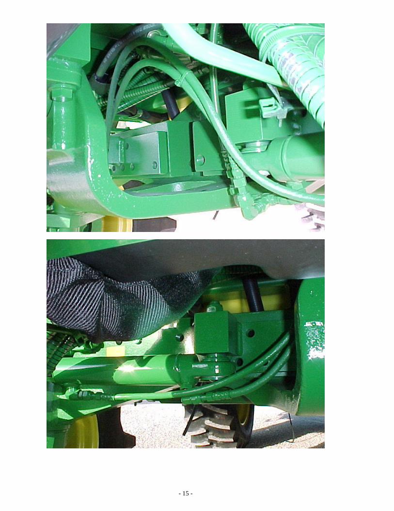
- 15 -

- 16 -

- 17 -

- 18 -

VALVE BASE ASSEMBLY (SERVICE PARTS ONLY) Item QtyPer Part Number Description
1 1 208149-P1 90° ELBOW (08 JIC-FS x 08 JIC-M) 2 2 208032-P1 SWIVEL RUN TEE (08 JIC-FS x 08 JIC-M x 08 JIC-M) 3 1 200083-P1 ADAPTER (06 ORB-M x 08 JIC-M) 4 4 200041-P1 ADAPTER (12 ORB-M x 08 JIC-M) 5 4 200163 HEX SOCKET PLUG (1/4 ORB-M) 6 2 101679-M1 ADAPTER (12 ORB-M x 04 ORB-F) 7 1 103715 SOLENOID CARTRIDGE VALVE 8 1 103924 SOLENOID COIL 9 1 204041-P1 ADAPTER (04 ORB-M x 04 JIC-M) 10 1 103709 TUBE ASSEMBLY, PILOT PRESSURE 11 1 200225 TEE (04 ORB-M x 04 JIC-M x 04 JIC-M) 12 1 200110-P1 CAP (04 JIC-F) NI 1 150346 SEAL KIT - ET-II (ORB O-RINGS)
NI = NOT ILLUSTRATED

ITEM # QTY. PART# DESCRIPTION
010 1 150309 Cylinder Block Assembly
012 8 150288 Piston Kit
015 1 150324 Piston Retainer Kit
025 1 104341 Cam Ring plus O-Rings
027 2 104342 O-Ring - Cam Ring
041 1 105174 Distributor Cover
042 12 105518 Socket Head Cap Screw M16x100
043 2 104106 Bleed Screw Seal
044 2 104350 Bleed Screw
045 1 103929 O-Ring - Cover Plate
047 1 104756 Distributor Valve
048 1 150290 Distributor Seal Kit
052 9 103922 Spring
053 1 104761 Spool - 2 Speed
054 1 104763 Washer - 2 Speed
055 1 104764 Snap Ring - 2 Speed
056 1 104762 Spring - 2 Speed
057 1 104760 O-Ring - 2 Speed
065 1 104759 Cover Plate
066 4 101865-P1 Hex Head Bolt M16 x 35
070 1 150392 Bearing Support Assembly
071 1 106195 Bearing Support
072 1 150311 Shaft Seal (Inner)
073 1 106196 Bearing (Outer)
074 1 104335 Bearing (Inner)
075 1 104337 Shim Pack
076 1 104336 Snap Ring Spacer
077 1 106250 Snap Ring
078 1 106197 Grease Seal
079 1 105506 Deflector
090 1 106198 Shaft, Wheel Hub
091 10 105672 Stud - M20 x 70
NI 10 104681 Lug Nut, M20
Seal Kit # 150396 contains item numbers 27, 45, 72, 75, 76, 77.
Seal Kit # 150397 contains item numbers 27, 43, 45, 48, 72, 75, 76, 77, 78, 79.
See illustration on following page (NI=not illustrated).
702403-01 - LH & 702403-02 - RH (76 cu.in. S11 2sp w/Reinforced Flange)
WHEEL MOTOR SERVICE PARTS


4WD Mud Hog® Vinyl Decal Application Instructions To apply your decal, please follow the instructions below:
1. Clean area above rear wheel on ladder side of machine to remove dirt and grime.
2. Without removing the paper backing, position decal on surface exactly where you want it.
3. Once the decal is in position, place a piece of masking tape along the top edge to
hold the decal in place. 4. The decal should be sitting on the surface like a flap. Lift up the decal and
remove the paper backing.
5. With the backing paper completely removed from the decal & transfer tape, gently lower the decal with the transfer tape back down to the surface and rub it down lightly with your hand.
6. The transfer tape should still be on the side of the decal facing you. This allows
you to rub the decal without scratching or damaging the decal. Take a squeegee or credit card and firmly rub the transfer tape and thus the decal until it is firmly adhered to the surface.
7. Finally, peel off the transfer tape and masking tape gently. The decal will adhere
to the surface much more aggressively than the transfer tape. The transfer tape should lift easily leaving behind no sticky residue.
8. Your decal installation is complete. If there are bubbles present under the decal
that cannot be removed by working them to edge, a small needle or pin can be used to puncture the bubble and remove the air. A small pin hole will not be seen after the air bubble has been worked out.

LIMITED WARRANTY Tuthill Drive Systems (“Tuthill”) warrants Mud Hog drive systems and components to be free from defects in material and workmanship under normal use and service as shown in the chart below from the date of shipment from Tuthill. Installed By: Warranty Period Tuthill Drive Systems – Mud Hog 24 months parts and 12 months labor for the Mud Hog kit & Installation. Authorized Mud Hog Dealer 24 months parts and 12 months labor for the Mud Hog kit. Note: Any defects resulting from installation errors are covered by the installer. Warranty period start date is determined by ship date from Tuthill Drive Systems. Normal use and service means that the product will be installed by a qualified mechanic, operated, inspected and maintained in accordance with the applicable Mud Hog manual or instructions and any applicable vehicle manufacturer’s manual or instructions. Tuthill is not liable for any printing errors contained within manuals. THE ABOVE WARRANTY IS EXCLUSIVE. TUTHILL MAKES NO OTHER REPRESENTATIONS OR WARRANTIES, EXPRESS OR IMPLIED, INCLUDING BUT NOT LIMITED TO ANY IMPLIED WARRANTY OF MERCHANTABILITY OR FITNESS FOR ANY PARTICULAR PURPOSE. No agent, distributor, dealer or employee of Tuthill has authority to extend the scope of this warranty. This warranty applies only to products which are sold and used only in the United States, Canada and Mexico. [Tuthill does not itself warrant components which bear the name or trademark of another manufacturer. Any warranty or remedy for such parts is limited to the extent of any warranty provided by the manufacturer to Tuthill.] No warranty applies in the event of replacement of parts with parts not obtained from or approved by Tuthill which do not meet Tuthill quality and performance specifications, improper installation, maintenance, repair, misuse or abuse, or unauthorized alteration or modification. Wheel motor warranty will be denied if the motor is disassembled and or serviced by anyone other than an authorized Tuthill service center within the warranty period. Tuthill reserves the right to make changes and improvements in design, specifications or instructions without notice and without obligation to provide or to substitute new design modifications for those Mud Hog systems or components already in service. Tuthill will at its option refund the purchase price of, or repair or replace without charge for parts, any Mud Hog product determined by Tuthill to be defective in material or workmanship during the applicable warranty period. Labor allowance, if applicable, will be determined in accordance with Tuthill’s warranty labor rate and time allowances established from time to time. These remedies are exclusive. In no event shall Tuthill’s liability exceed the purchase price for the Mud Hog product when sold by Tuthill to the first buyer. Tuthill shall not be liable for any incidental or consequential damage or expense resulting from any product defect, including but not limited to loss of profits, loss of use of equipment, increased costs or other expenses. This warranty shall become effective only when the Warranty Certificate has been returned to Tuthill and validated by same.
INSTALLER AND OWNER RESPONSIBILITIES
The installer is responsible for installing the product according to Tuthill’s approved procedures, for providing a copy of Tuthill’s warranty and installation/parts manual to the owner, and for advising the owner of proper use, service, and maintenance required for the product. The owner is responsible for operation, inspecting and maintaining the product according to the instructions in the installation/parts manual and any applicable vehicle manufacturer’s owner’s manual, and for properly instructing all operators and maintenance personnel.
ADJUSTMENTS When adjustment is sought under this warranty, a claim should be made as follows: A. Tuthill must be notified in writing promptly upon discovery of a claimed defect. B. If the product was installed by the vehicle manufacturer (or it’s dealer), follow the manufacturer’s procedures for warranty
claims; or If the product was purchased from Tuthill through a distributor of Mud Hog products, have the distributor write or phone the Tuthill Customer Service Department and ask for a Returned Goods Authorization Number (RGA#). A warranty claim form will be submitted with information including: The RGA#, Tuthill axle serial #, retail sales date, machine hours and a description of the failure.
C. Components requested by Tuthill must be returned freight prepaid and accompanied by a properly completed warranty claim form. Tuthill will specify the ship-to address at time of return approval.
9098 W. 800 S., Brookston, IN 47923, Tel: 219-279-2801 / 800-348-2474 Fax: 219-279-2390 Email: [email protected] Web: www.tuthill.com


![A COMPARISON OF KAPLAN-MEIER AND CUMULATIVE INCIDENCE ...d-scholarship.pitt.edu/9986/1/BintuSherif_thesis[1].pdf · a comparison of kaplan-meier and cumulative incidence estimate](https://static.fdocuments.in/doc/165x107/5ad1fe937f8b9a92258c90e6/a-comparison-of-kaplan-meier-and-cumulative-incidence-d-1pdfa-comparison-of.jpg)


