JLG Lift Models: 400RTS - Amazon S3 · foreword 3120695 – jlg sizzor – a foreword danger...
47
Operation & Safety Manual Models 400RTS 500RTS 3120695 November 9, 2007
Transcript of JLG Lift Models: 400RTS - Amazon S3 · foreword 3120695 – jlg sizzor – a foreword danger...

Operation & Safety Manual
Models400RTS500RTS
3120695November 9, 2007
FOREWORD
3120695 – JLG Sizzor – a
FOREWORD
DANGER INDICATES AN IMMINENTLY HAZARDOUS SITUATIONWHICH, IF NOT AVOIDED WILL RESULT IN SERIOUS INJURY ORDEATH.
CAUTION INDICATES A POTENTIALLY HAZARDOUS SITUATIONWHICH, IF NOT AVOIDED, MAY RESULT IN MINOR OR MODERATEINJURY. IT MAY ALSO BE USED TO ALERT AGAINST UNSAFEPRACTICES
WARNING INDICATES A POTENTIALLY HAZARDOUS SITUATIONWHICH, IF NOT AVOIDED COULD RESULT IN SERIOUS INJURYOR DEATH.
IMPORTANT OR INSTRUCTIONS INDICATES A PROCEDURESESSENTIAL FOR SAFE OPERATION AND WHICH, IF NOT FOL-LOWED, MAY RESULT IN A MALFUNCTION OR DAMAGE TO THEMACHINE.
The purpose of this manual is to provide users with the operating procedures essential for the promotion of proper machineoperation for its intended purpose. It is important to over-stress proper machine usage. All information in this manual shouldbe READ and UNDERSTOOD before any attempt is made to operate the machine. YOUR OPERATING MANUAL ISYOUR MOST IMPORTANT TOOL - Keep it with the machine. REMEMBER ANY EQUIPMENT IS ONLY ASSAFE AS THE OPERATOR.
BECAUSE THE MANUFACTURER HAS NO DIRECT CONTROL OVER MACHINE APPLICATION ANDOPERATION, PROPER SAFETY PRACTICES ARE THE RESPONSIBILITY OF THE USER AND HIS OPER-ATING PERSONNEL.
ALL INSTRUCTIONS IN THIS MANUAL ARE BASED ON THE USE OF THE MACHINE UNDER PROPEROPERATING CONDITIONS, WITH NO DEVIATIONS FROM THE ORIGINAL DESIGN. ALTERATION AND/OR MODIFICATION OF THE MACHINE IS STRICTLY FORBIDDEN, WITHOUT WRITTEN APPROVALFROM JLG INDUSTRIES, PER OSHA REGULATIONS.
THIS SAFETY ALERT SYMBOL IS USED TO CALL ATTENTION TO POTENTIAL HAZARDS WHICHMAY LEAD TO SERIOUS INJURY OR DEATH IF IGNORED.
Safety of personnel and proper use of the machine are of primary concern, DANGER, WARNING, CAUTION,IMPORTANT, INSTRUCTIONS and NOTE are inserted throughout this manual to emphasize these areas. They aredefined as follows:
JLG INDUSTRIES MAY HAVE ISSUED SAFETY RELATED BULLETINS FOR YOUR JLG PRODUCT. CONTACT JLG INDUSTRIES INC.OR THE LOCAL AUTHORIZED JLG DISTRIBUTOR FOR INFORMATION CONCERNING SAFETY RELATED BULLETINS WHICH MAYHAVE BEEN ISSUED FOR YOUR JLG PRODUCT. ALL ITEMS REQUIRED BY THE SAFETY RELATED BULLETINS MUST BE COM-PLETED ON THE AFFECTED JLG PRODUCT. CALL 1 - 877 - JLG - SAFE
Due to continuous product improvements, JLG Industries, Inc. reserves the right to make specification changes without prior notifica-tion. Contact JLG Industries, Inc. for updated information.

FOREWORD
b – JLG Sizzor – 3120695
All procedures herein are based on the use of the machineunder proper operating conditions, with no deviationsfrom original design intent... as per OSHA regulations.
READ & HEED!
The ownership, use, service, and/or maintenance of thismachine is subject to various governmental and local lawsand regulations. It is the responsibility of the owner/userto be knowledgeable of these laws and regulations and tocomply with them. Owner/user/operator must be familiarwith Sections 6,7,8,9, and 10 of ANSI A92.6-1999. Thesesections contain the responsibilities of the owner, users,operators, lessors, and lessees concerning safety, training,inspection, maintenance, application and operation. Themost prevalent regulations of this type in the United Statesare the Federal OSHA Safety Regulations*. Listed below,in abbreviated form are some of the requirements of Fed-eral OSHA regulations in effect as of the date of publica-tion of this handbook.
The listing of these requirements shall not relieve theowner/user of the responsibility and obligation to deter-mine all applicable laws and regulations and their exactwording and requirements, and to comply with therequirements. Nor shall the listing of these requirementsconstitute an assumption of responsibility of liability onthe part of JLG Industries, Inc.
1. Only trained and authorized operators shall be per-mitted to operate the aerial lift.
2. A malfunctioning lift shall be shut down untilrepaired.
3. The controls shall be plainly marked as to their func-tion.
4. The controls shall be tested each day prior to use todetermine that they are in safe operating condition.
5. All personnel in the platform shall, at all times, wearapproved fall protection devices and other safetygear as required.
6. Load limits specified by the manufacturer shall notbe exceeded.
7. Instruction and warning placards must be legible.
8. Aerial lifts may be field modified for uses other thanthose intended by the manufacturer only if certifiedin writing by the manufacturer to be in conformity to
JLG requirements and to be at least as safe as it wasprior to modification.
9. Aerial lifts shall not be used near electric powerlines unless the lines have been de energized or ade-quate clearance is maintained (See OSHA 29 CFR1910.67 and 1926.453).
10. Employees using aerial lifts shall be instructed onhow to recognize and avoid unsafe conditions andhazards.
11. Ground controls shall not be operated unless permis-sion has been obtained from personnel in the plat-form, except in case of an emergency.
12. Regular inspection of the job site and aerial lift shallbe performed by competent persons.
13. Personnel shall always stand on the floor of the plat-form, not on boxes, planks, railing or other devices,for a work position.
*Applicable Federal OSHA regulations for the UnitedStates, as of the date of publication of this manual,include, but are not limited to, 29 CFR 1910.67, 29 CFR1926.20, 29 CFR 1926.21, 29 CFR 1926.28, and 29 CFR1926.453.

FOREWORD
3120695 – JLG Sizzor – c
REVISION LOGJune 1, 1993 - Original IssueMay 6, 1999 - RevisedOctober 29, 1999 - RevisedPro 65 page added - Updated 4-19-00Revised - Updated 4-19-00Revised August 20, 2002Revised December 5, 2002Revised September 26, 2007Revised November 9, 2007

FOREWORD
d – JLG Sizzor – 3120695
This page left blank intentionally.

3120695 – JLG Sizzor – i
TABLE OF CONTENTS
TABLE OF CONTENTS
SUBJECT - SECTION, PARAGRAPH PAGE NO.
TABLE OF CONTENTS
SECTION -
SECTION - FOREWORD
SECTION 1 - SAFETY PRECAUTIONS
1.1 General . . . . . . . . . . . . . . . . . . . . . . . . . . . . . . . . . . . . . . . . . . . . . . . . . . . . . . . . . . . . . . . . . . . . . .1-11.2 Driving/Towing/Carrying . . . . . . . . . . . . . . . . . . . . . . . . . . . . . . . . . . . . . . . . . . . . . . . . . . . . . . . . .1-11.3 Electrocution Hazard. . . . . . . . . . . . . . . . . . . . . . . . . . . . . . . . . . . . . . . . . . . . . . . . . . . . . . . . . . . .1-21.4 Pre-operational . . . . . . . . . . . . . . . . . . . . . . . . . . . . . . . . . . . . . . . . . . . . . . . . . . . . . . . . . . . . . . . .1-31.5 Driving . . . . . . . . . . . . . . . . . . . . . . . . . . . . . . . . . . . . . . . . . . . . . . . . . . . . . . . . . . . . . . . . . . . . . . .1-41.6 Operation. . . . . . . . . . . . . . . . . . . . . . . . . . . . . . . . . . . . . . . . . . . . . . . . . . . . . . . . . . . . . . . . . . . . .1-41.7 Towing and Hauling . . . . . . . . . . . . . . . . . . . . . . . . . . . . . . . . . . . . . . . . . . . . . . . . . . . . . . . . . . . .1-61.8 Maintenance . . . . . . . . . . . . . . . . . . . . . . . . . . . . . . . . . . . . . . . . . . . . . . . . . . . . . . . . . . . . . . . . . .1-6
SECTION 2 - MACHINE PREPARATION AND INSPECTION
2.1 General . . . . . . . . . . . . . . . . . . . . . . . . . . . . . . . . . . . . . . . . . . . . . . . . . . . . . . . . . . . . . . . . . . . . . .2-12.2 Preparation for Use . . . . . . . . . . . . . . . . . . . . . . . . . . . . . . . . . . . . . . . . . . . . . . . . . . . . . . . . . . . . .2-12.3 Delivery and Periodic Inspection . . . . . . . . . . . . . . . . . . . . . . . . . . . . . . . . . . . . . . . . . . . . . . . . . .2-12.4 Daily Walk-Around Inspection. . . . . . . . . . . . . . . . . . . . . . . . . . . . . . . . . . . . . . . . . . . . . . . . . . . . .2-22.5 Daily Functional Check . . . . . . . . . . . . . . . . . . . . . . . . . . . . . . . . . . . . . . . . . . . . . . . . . . . . . . . . . .2-32.6 Lockout Cylinder Check (If Equipped) . . . . . . . . . . . . . . . . . . . . . . . . . . . . . . . . . . . . . . . . . . . . . .2-42.7 Dual Fuel System . . . . . . . . . . . . . . . . . . . . . . . . . . . . . . . . . . . . . . . . . . . . . . . . . . . . . . . . . . . . . .2-82.8 Torque Requirements . . . . . . . . . . . . . . . . . . . . . . . . . . . . . . . . . . . . . . . . . . . . . . . . . . . . . . . . . . .2-8
SECTION 3 - USER RESPONSIBILITIES AND MACHINE CONTROL
3.1 General . . . . . . . . . . . . . . . . . . . . . . . . . . . . . . . . . . . . . . . . . . . . . . . . . . . . . . . . . . . . . . . . . . . . . .3-13.2 Personnel Training . . . . . . . . . . . . . . . . . . . . . . . . . . . . . . . . . . . . . . . . . . . . . . . . . . . . . . . . . . . . .3-13.3 Operating Characteristics and Limitations . . . . . . . . . . . . . . . . . . . . . . . . . . . . . . . . . . . . . . . . . . .3-13.4 Controls and Indicators . . . . . . . . . . . . . . . . . . . . . . . . . . . . . . . . . . . . . . . . . . . . . . . . . . . . . . . . . .3-2
SECTION 4 - MACHINE OPERATION
4.1 Description . . . . . . . . . . . . . . . . . . . . . . . . . . . . . . . . . . . . . . . . . . . . . . . . . . . . . . . . . . . . . . . . . . .4-14.2 General . . . . . . . . . . . . . . . . . . . . . . . . . . . . . . . . . . . . . . . . . . . . . . . . . . . . . . . . . . . . . . . . . . . . . .4-14.3 Engine Operation . . . . . . . . . . . . . . . . . . . . . . . . . . . . . . . . . . . . . . . . . . . . . . . . . . . . . . . . . . . . . .4-24.4 Raising and Lowering (Lifting) . . . . . . . . . . . . . . . . . . . . . . . . . . . . . . . . . . . . . . . . . . . . . . . . . . . .4-24.5 Traversing Platform (Optional) . . . . . . . . . . . . . . . . . . . . . . . . . . . . . . . . . . . . . . . . . . . . . . . . . . . .4-34.6 Steering . . . . . . . . . . . . . . . . . . . . . . . . . . . . . . . . . . . . . . . . . . . . . . . . . . . . . . . . . . . . . . . . . . . . . .4-34.7 Traveling (Driving) . . . . . . . . . . . . . . . . . . . . . . . . . . . . . . . . . . . . . . . . . . . . . . . . . . . . . . . . . . . . . .4-34.8 Parking and Stowing . . . . . . . . . . . . . . . . . . . . . . . . . . . . . . . . . . . . . . . . . . . . . . . . . . . . . . . . . . . .4-44.9 Platform Loading . . . . . . . . . . . . . . . . . . . . . . . . . . . . . . . . . . . . . . . . . . . . . . . . . . . . . . . . . . . . . . .4-44.10 Safety Props . . . . . . . . . . . . . . . . . . . . . . . . . . . . . . . . . . . . . . . . . . . . . . . . . . . . . . . . . . . . . . . . . .4-54.11 Machine Tie Down. . . . . . . . . . . . . . . . . . . . . . . . . . . . . . . . . . . . . . . . . . . . . . . . . . . . . . . . . . . . . .4-54.12 Towing . . . . . . . . . . . . . . . . . . . . . . . . . . . . . . . . . . . . . . . . . . . . . . . . . . . . . . . . . . . . . . . . . . . . . . .4-5
SECTION 5 - EMERGENCY PROCEDURES
5.1 General . . . . . . . . . . . . . . . . . . . . . . . . . . . . . . . . . . . . . . . . . . . . . . . . . . . . . . . . . . . . . . . . . . . . . .5-15.2 Emergency Towing Procedures . . . . . . . . . . . . . . . . . . . . . . . . . . . . . . . . . . . . . . . . . . . . . . . . . . .5-15.3 Emergency Controls and Their Locations . . . . . . . . . . . . . . . . . . . . . . . . . . . . . . . . . . . . . . . . . . .5-15.4 Emergency Operation . . . . . . . . . . . . . . . . . . . . . . . . . . . . . . . . . . . . . . . . . . . . . . . . . . . . . . . . . . .5-25.5 Incident Notification. . . . . . . . . . . . . . . . . . . . . . . . . . . . . . . . . . . . . . . . . . . . . . . . . . . . . . . . . . . . .5-3
SECTION 6 - INSPECTION AND REPAIR LOG

ii – JLG Sizzor – 3120695
TABLE OF CONTENTS (Continued)
LIST OF FIGURES
FIGURE NO. TITLE PAGE NO.
2-1. Daily Walk-Around Inspection Diagram . . . . . . . . . . . . . . . . . . . . . . . . . . . . . . . . . . . . . . . . . . . . .2-52-2. Walk-Around Inspection Points (Sheet 1 of 3) . . . . . . . . . . . . . . . . . . . . . . . . . . . . . . . . . . . . . . . .2-62-3. Walk-Around Inspection Points (Sheet 2 of 3) . . . . . . . . . . . . . . . . . . . . . . . . . . . . . . . . . . . . . . . .2-72-4. Walk-Around Inspection Points (Sheet 3 of 3) . . . . . . . . . . . . . . . . . . . . . . . . . . . . . . . . . . . . . . . .2-82-5. Lubrication Diagram . . . . . . . . . . . . . . . . . . . . . . . . . . . . . . . . . . . . . . . . . . . . . . . . . . . . . . . . . . . .2-92-6. Torque Chart . . . . . . . . . . . . . . . . . . . . . . . . . . . . . . . . . . . . . . . . . . . . . . . . . . . . . . . . . . . . . . . . . .2-113-1. Ground Control Station . . . . . . . . . . . . . . . . . . . . . . . . . . . . . . . . . . . . . . . . . . . . . . . . . . . . . . . . . .3-23-2. Platform Control Station . . . . . . . . . . . . . . . . . . . . . . . . . . . . . . . . . . . . . . . . . . . . . . . . . . . . . . . . .3-43-3. Control Panel Symbols . . . . . . . . . . . . . . . . . . . . . . . . . . . . . . . . . . . . . . . . . . . . . . . . . . . . . . . . . .3-63-4. Decal Location - Right Side (Sheet 1 of 2) . . . . . . . . . . . . . . . . . . . . . . . . . . . . . . . . . . . . . . . . . . .3-73-5. Decal Location - Left Side (Sheet 2 of 2) . . . . . . . . . . . . . . . . . . . . . . . . . . . . . . . . . . . . . . . . . . . .3-84-1. Grade and Sideslope . . . . . . . . . . . . . . . . . . . . . . . . . . . . . . . . . . . . . . . . . . . . . . . . . . . . . . . . . . .4-35-1. Drive Hub Disconnect . . . . . . . . . . . . . . . . . . . . . . . . . . . . . . . . . . . . . . . . . . . . . . . . . . . . . . . . . . .5-15-2. Drive Hub Connect . . . . . . . . . . . . . . . . . . . . . . . . . . . . . . . . . . . . . . . . . . . . . . . . . . . . . . . . . . . . .5-1
LIST OF TABLES
TABLE NO. TITLE PAGE NO.
1-1 Minimum Approach Distances (M.A.D.) to energized (exposed or insulated) power lines and parts . . . . . . . . . . . . . . . . . . . . . . . . . . . . . . . . . . . . . . . . . . . . . . . . . . . . . . . . . . . . . . . . . . . .1-2
2-1 Lubrication Chart . . . . . . . . . . . . . . . . . . . . . . . . . . . . . . . . . . . . . . . . . . . . . . . . . . . . . . . . . . . . . . .2-106-1 Inspection and Repair Log . . . . . . . . . . . . . . . . . . . . . . . . . . . . . . . . . . . . . . . . . . . . . . . . . . . . . . .6-1

SECTION 1 - SAFETY PRECAUTIONS
3120695 – JLG Sizzor – 1-1
SECTION 1. SAFETY PRECAUTIONS
1.1 GENERALThis section prescribes the proper and safe practices formajor areas of machine usage which have been dividedinto three basic categories: Driving, Operation, and Main-tenance. In order to promote proper usage of themachine, it is mandatory that a daily routine be estab-lished based on the instructions given in this manual. Amaintenance program, using the information provided inthe Service and Maintenance Manual, must also be estab-lished by a qualified person and must be followed toensure that the machine is safe to operate.
The owner/user/operator/lessor/lessee of the machineshould not accept operating responsibility until this man-ual has been read and operation of the machine, underthe supervision of an experienced and qualified operator,has been completed. Owner/user/operator/lessor/lesseemust be familiar with Sections 6, 7, 8, 9, and 10 of ANSIA92.6 -1999. These sections contain the responsibilities ofthe owner, users, operators, lessors and lessees concern-ing safety, training, inspection, maintenance, applicationand operation. If there is a question on application and oroperation, JLG Industries should be consulted
MODIFICATION OR ALTERATION OF AN AERIAL PLATFORMSHALL BE MADE ONLY WITH PRIOR WRITTEN PERMISSION OFTHE MANUFACTURER.
1.2 DRIVING/TOWING/CARRYINGBefore driving the machine the user must be familiar withthe drive, steer and stopping characteristics. This is espe-cially important when driving in close quarters.
The user should be familiar with the driving surface beforedriving. The surface should be firm and level and gradesshould not exceed the allowable grade for the machine,25%.
NOTE: Remember that the key to safe and proper usage iscommon sense and its careful application.
It is not recommended that this machine be towed, exceptin the event of a machine malfunction, a total machinepower failure, or for loading on a truck. Refer to Section 6for emergency towing procedures.
FAILURE TO COMPLY WITH SAFETY PRECAUTIONS LISTED INTHIS SECTION AND ON MACHINE MAY RESULT IN MACHINEDAMAGE, PERSONNEL INJURY OR DEATH AND IS A SAFETYVIOLATION.
Carrying or loading the unit should be accomplishedusing a forklift vehicle of suitable capacity with the forksbeing positioned correctly at the indicated areas on themachine frame. Refer to Section 4 for lifting information.

SECTION 1 - SAFETY PRECAUTIONS
1-2 – JLG Sizzor – 3120695
1.3 ELECTROCUTION HAZARD
DO NOT MANEUVER MACHINE OR PERSONEL INSIDE PROHIB-ITED ZONE. ASSUME ALL ELECTRICAL PARTS AND WIRING AREENERGIZED UNLESS KNOWN OTHERWISE.
NOTE: MAINTAIN M.A.D. FROM ALL OTHER CHARGEDLINES AND PARTS AS WELL AS THOSE SHOWN.
M.A.D. = MINIMUM APPROACH DISTANCE
(SEE TABLE BELOW)
MAINTAIN SAFE CLEARANCE FROM ELECTRICAL LINESAND APPARATUS. ALLOW FOR PLATFORM SWAY, ROCKOR SAG AND ELECTRICAL LINE SWAYING. THEMACHINE DOES NOT PROVIDE PROTECTION FROMCONTACT WITH OR PROXIMITY TO ELECTRICAL CUR-RENT.
MAINTAIN A CLEARANCE OF AT LEAST 10 FEET (3 M)BETWEEN ANY PART OF THE MACHINE OR ITS LOADAND ANY ELECTRICAL LINE OR APPARATUS CARRYINGUP TO 50,000 VOLTS. ONE FOOT (0.3 M) ADDITIONALCLEARANCE IS REQUIRED FOR EVERY ADDITIONAL30,000 VOLTS OR LESS.
Table 1-1.Minimum Approach Distances (M.A.D.) to energized
(exposed or insulated) power lines and parts
VOLTAGE RANGE(Phase To Phase)
MINIMUM APPROACH DISTANCEFeet (Meters)
0 to 300V AVOID CONTACT
Over 300V to 50KV 10 (3)
Over 50KV to 200KV 15 (5)
Over 200KV to 350KV 20 (6)
Over 350KV to 500KV 25 (8)
Over 500KV to 750KV 35 (11)
Over 750KV to 1000KV 45 (14)

SECTION 1 - SAFETY PRECAUTIONS
3120695 – JLG Sizzor – 1-3
1.4 PRE-OPERATIONAL
• READ YOUR MANUAL. UNDERSTAND WHAT YOU’VEREAD - THEN BEGIN OPERATIONS.
• ALLOW ONLY THOSE AUTHORIZED AND QUALIFIEDPERSONNEL TO OPERATE MACHINE WHO HAVEDEMONSTRATED THAT THEY UNDERSTAND SAFEAND PROPER OPERATION AND MAINTENANCE OFTHE UNIT.
• AN OPERATOR MUST NOT ACCEPT OPERATINGRESPONSIBILITIES UNTIL ADEQUATE TRAINING HASBEEN GIVEN BY COMPETENT AND AUTHORIZEDPERSONS.
• READ AND OBEY ALL WARNINGS, CAUTIONS ANDOPERATING INSTRUCTIONS ON MACHINE AND INTHIS MANUAL.
• BE FAMILIAR WITH LOCATION AND OPERATION OFGROUND CONTROLS.
• BEFORE OPERATION CHECK WORK AREA FOROVERHEAD ELECTRIC LINES, MACHINE TRAFFICSUCH AS BRIDGE CRANES, HIGHWAY, RAILWAY ANDCONSTRUCTION EQUIPMENT.
• PRECAUTIONS TO AVOID ALL KNOWN HAZARDS INTHE WORK AREA MUST BE TAKEN BY THE OPERA-TOR AND HIS SUPERVISOR BEFORE STARTING THEWORK.
• DO NOT OPERATE THIS MACHINE UNLESS IT HASBEEN SERVICED AND MAINTAINED ACCORDING TOTHE MANUFACTURERS SPECIFICATIONS ANDSCHEDULE.
• ENSURE DAILY INSPECTION AND FUNCTION CHECKARE PERFORMED PRIOR TO PLACING MACHINEINTO OPERATION.
• NEVER DISABLE OR MODIFY ANY SAFETY DEVICE.ANY MODIFICATION OF THE MACHINE IS A SAFETYVIOLATION AND IS A VIOLATION OF OSHA RULES.
• DO NOT OPERATE MACHINE WHEN WIND CONDI-TIONS EXCEED 30 MPH.
• NEVER OPERATE OR RAISE PLATFORM WHENMACHINE IS ON A TRUCK OR OTHER VEHICLE.
• THIS MACHINE CAN BE OPERATED IN NOMINALAMBIENT TEMPERATURES OF 0° F TO 104° F (-20° CTO 40° C). CONSULT FACTORY TO OPTIMIZE OPER-ATION OUTSIDE THIS TEMPERATURE RANGE
.
• APPROVED HEAD GEAR MUST BE WORN WHENREQUIRED BY ALL OPERATING AND GROUND PER-SONNEL.
• ALWAYS USE ‘THREE POINT CONTACT’ WITH THEMACHINE. FACE THE MACHINE WHEN ENTERINGOR LEAVING THE PLATFORM. ‘THREE POINT CON-TACT’ MEANS THAT TWO HANDS AND ONE FOOTOR ONE HAND AND TWO FEET ARE IN CONTACTWITH THE MACHINE AT ALL TIMES DURING MOUNTAND DISMOUNT.

SECTION 1 - SAFETY PRECAUTIONS
1-4 – JLG Sizzor – 3120695
1.5 DRIVING
• WATCH FOR OBSTRUCTIONS AROUND MACHINEAND OVERHEAD WHEN DRIVING.
• CHECK TRAVEL PATH FOR PERSONS, HOLES,BUMPS, DROP-OFF, OBSTRUCTIONS, DEBRIS, ANDCOVERINGS WHICH MAY CONCEAL HOLES ANDOTHER HAZARDS.
• DO NOT DRIVE WITH PLATFORM RAISED OR RAISEPLATFORM WHILE ON A SLOPING, UNEVEN, ORSOFT SURFACE.
• BEFORE DRIVING ON FLOORS, BRIDGES, TRUCKSAND OTHER SURFACES, CHECK ALLOWABLECAPACITY OF SURFACES.
• DO NOT TRAVEL ON SOFT OR UNEVEN SURFACES,AS TIPPING WILL OCCUR.
• WHEN DRIVING IN HIGH SPEED, SWITCH TO LOWBEFORE STOPPING. TRAVEL GRADES IN LOW DRIVEONLY. THE HYDRAULIC MOTORS GENERATE MAXI-MUM TORQUE WHEN THE JOYSTICK IS PLACED INTHE SLOW DRIVE POSITION. MOTORS ALSO ACT ASSERVICE BRAKES.
• DO NOT USE HIGH SPEED DRIVE IN RESTRICTEDOR CLOSE QUARTERS OR WHEN DRIVING INREVERSE.
• BE AWARE OF STOPPING DISTANCES WHEN TRAV-ELING IN HIGH AND LOW SPEEDS.
• ALWAYS POST A LOOKOUT WHEN DRIVING INAREAS WHERE VISION IS OBSTRUCTED.
• KEEP NON-OPERATING PERSONNEL AT LEAST 6FEET (1.8 M) AWAY FROM MACHINE DURING DRIV-ING OPERATIONS.
1.6 OPERATION
• READ YOUR MANUAL, UNDERSTAND WHAT YOU’VEREAD - THEN BEGIN OPERATIONS.
• DO NOT OPERATE ANY MACHINE ON WHICH DAN-GER, WARNING, CAUTION OR INSTRUCTION PLAC-ARDS OR DECALS ARE MISSING OR ILLEGIBLE.
• NEVER USE SCISSOR ARMS TO GAIN ACCESS TOOR LEAVE PLATFORM.
• WHEN APPLICABLE BY REASON OF LOCAL REGULA-TIONS OR JOBSITE/EMPLOYER SAFETY RULES, ALLPERSONNEL IN THE PLATFORM SHALL AT ALLTIMES WEAR APPROVED FALL PROTECTIONDEVICES AND OTHER SAFETY GEAR AS REQUIRED.
• TO AVOID FALLING - USE EXTREME CAUTION WHENENTERING OR LEAVING PLATFORM AB OVEGROUND. ENTER OR EXIT THRU GATE ONLY. PLAT-FORM MUST BE WITHIN 1 FT (0.3 M) OF ADJACENT -SAFE AND SECURE - STRUCTURE.

SECTION 1 - SAFETY PRECAUTIONS
3120695 – JLG Sizzor – 1-5
• TRANSFERS BETWEEN A STRUCTURE AND THEPLATFORM EXPOSE OPERATORS TO FALL POTEN-TIALS. THIS PRACTICE SHOULD BE DISCOURAGEDWHEREVER POSSIBLE. WHERE TRANSFER MUSTBE ACCOMPLISHED TO PERFORM THE JOB, TWOLANYARDS WILL BE USED. ONE LANYARD SHOULDBE ATTACHED TO THE PLATFORM, THE OTHER TOTHE STRUCTURE. THE SAFETY LANYARD THAT ISATTACHED TO THE PLATFORM SHOULD NOT BEDISCONNECTED UNTIL SUCH TIME AS THE TRANS-FER TO THE STRUCTURE IS COMPLETE.
• NEVER POSITION LADDERS, STEPS, OR SIMILARITEMS ON UNIT TO PROVIDE ADDITIONAL REACHFOR ANY PURPOSE.
• WHEN RIDING IN OR WORKING FROM PLATFORMBOTH FEET MUST BE FIRMLY POSITIONED ONDECK.
• DO NOT EXTEND REACH LIMITS OF THIS MACHINEWITH ADDITIONAL EQUIPMENT SUCH AS PLANKS,BOXES, ETC.
• DO NOT OPERATE WITHOUT HANDRAILS IN PLACEAND SECURED. IT IS A SAFETY VIOLATION.
• DO NOT STEP OUTSIDE OF HANDRAILS.
• AVOID ACCUMULATION OF DEBRIS ON PLATFORMWORK AREA. KEEP MUD, OIL, GREASE AND OTHERSLIPPERY SUBSTANCES FROM FOOTWEAR ANDPLATFORM DECK.
• CHECK CLEARANCES ABOVE, ON SIDES AND BOT-TOM OF PLATFORM WHEN RAISING AND LOWERINGPLATFORM.
• EXERCISE EXTREME CAUTION AT ALL TIMES TOPREVENT OBSTACLES FROM STRIKING OR INTER-FERING WITH OPERATING CONTROLS AND PER-SONS IN THE PLATFORM.
• ENSURE THAT OPERATORS OF OTHER OVERHEADAND FLOOR LEVEL MACHINES ARE AWARE OF THEAERIAL PLATFORM’S PRESENCE. DISCONNECTPOWER TO OVERHEAD CRANES. BARRICADEFLOOR AREA IF NECESSARY.
• NEVER EXCEED MANUFACTURERS RATED PLAT-FORM CAPACITY - REFER TO CAPACITY DECAL ONMACHINE. DISTRIBUTE LOAD EVENLY ON PLAT-FORM FLOOR.
• ENSURE MACHINE IS POSITIONED ON A FIRM,LEVEL AND UNIFORM SUPPORTING SURFACEBEFORE RAISING PLATFORM.
• DO NOT ADD NOTICE BOARDS OR SIMILAR ITEMSTO PLATFORM. ADDIT ION OF SUCH ITEMSINCREASES EXPOSED WIND AREA OF MACHINE.
• DO NOT ATTACH OVERHANGING LOADS TO THEPLATFORM OR INCREASE THE PLATFORM SIZEWITH UNAUTHORIZED DECK EXTENSIONS ORATTACHMENTS.
• DO NOT ELEVATE PLATFORM UNLESS MACHINE ISLEVEL.
• DO NOT TIE OFF MACHINE TO ANY ADJACENTSTRUCTURE. NEVER ATTACH WIRE, CABLE OR ANYSIMILAR ITEMS TO PLATFORM.
• DURING OPERATION KEEP ALL BODY PARTS INSIDEPLATFORM RAILINGS.
• NEVER ‘SLAM’ A CONTROL SWITCH OR LEVERTHROUGH NEUTRAL TO OPPOSITE DIRECTION.ALWAYS RETURN SWITCH TO NEUTRAL AND STOP;THEN MOVE SWITCH TO THE DESIRED POSITION.OPERATE LEVERS WITH SLOW, EVEN PRESSURE.
• DO NOT CARRY MATERIALS ON PLATFORM RAILING
• NEVER OPERATE A MALFUNCTIONING MACHINE. IFA MALFUNCTION OCCURS, SHUT DOWN THE

SECTION 1 - SAFETY PRECAUTIONS
1-6 – JLG Sizzor – 3120695
MACHINE, RED TAG IT, AND NOTIFY PROPERAUTHORITIES.
• NO STUNT DRIVING OR HORSEPLAY IS PERMITTED.
• DO NOT ALLOW PERSONNEL TO TAMPER WITH,SERVICE, OR OPERATE THIS MACHINE FROM THEGROUND WITH PERSONNEL IN PLATFORM EXCEPTIN AN EMERGENCY.
• WHEN TWO OR MORE PERSONS ARE IN PLATFORM,THE OPERATOR SHALL BE RESPONSIBLE FOR ALLMACHINE OPERATIONS.
• ALWAYS ENSURE THAT POWER TOOLS ARE PROP-ERLY STOWED AND NEVER LEFT HANGING BYTHEIR CORD FROM THE PLATFORM WORK AREA.
1.7 TOWING AND HAULING• TOW OR PULL MACHINE IN THE EVENT OF AN
EMERGENCY ONLY. TO MOVE MACHINE, CARRYMACHINE WITH FORKLIFT OF SUITABLE CAPACITY.
• HAVE PLATFORM COMPLETELY EMPTY OF TOOLSAND DEBRIS BEFORE CARRYING.
• WHEN LIFTING MACHINE, POSITION FORKS ONLYAT DESIGNATED AREAS AT FRONT OR REAR OFMACHINE.
• HAVE PLATFORM FULLY RETRACTED WHILEMACHINE IS BEING CARRIED.
• NEVER ALLOW PERSONNEL IN PLATFORM WHILECARRYING.
1.8 MAINTENANCEThis section contains the general safety precautionswhich must be observed during maintenance of the aerialwork platform. It is of utmost importance that maintenancepersonnel pay strict attention to these warnings and pre-cautions to avoid possible injury to themselves or othersor damage to the equipment. A maintenance programmust be established by a qualified person and must befollowed to ensure that the machine is safe to operate.
MODIFICATION OF THE MACHINE WITHOUT CERTIFICATION BYA RESPONSIBLE AUTHORITY THAT THE MACHINE IS AT LEASTAS SAFE AS ORIGINALLY MANUFACTURED IS A SAFETY VIOLA-TION.
The specific precautions to be observed during machinemaintenance are inserted at the appropriate point in themanual. These precautions are, for the most part, thosethat apply when servicing hydraulic and larger machinecomponent parts.
Your safety, and that of others, is the first considerationwhen engaging in the maintenance of equipment. Alwaysbe conscious of weight.
Never attempt to move heavy parts without the aid of amechanical device. Do not allow heavy objects to rest inan unstable position. When raising a portion of the equip-ment, ensure that adequate support is provided.
• ALWAYS DISCONNECT BATTERIES WHEN REPLAC-ING ELECTRICAL COMPONENTS.
• REMOVE RINGS, WATCHES AND JEWELRY WHENPERFORMING ANY MAINTENANCE.
• DO NOT WEAR LOOSE FITTING CLOTHING OR LONGHAIR UNRESTRAINED, WHICH IS APT TO BECOMECAUGHT ON, OR ENTANGLED IN EQUIPMENT.
• USE ONLY CLEAN APPROVED NONFLAMMABLECLEANING SOLVENTS.
• SHUT OFF ALL POWER CONTROLS BEFORE MAK-ING ADJUSTMENTS, LUBRICATING OR PERFORM-ING ANY OTHER MAINTENANCE.
• NEVER WORK UNDER AN ELEVATED PLATFORMUNTIL IT HAS BEEN RESTRAINED FROM MOVEMENTWITH SAFETY PROPS, BLOCKING OR OVERHEADSLING.
• NEVER ALTER, REMOVE OR SUBSTITUTE ANYITEMS SUCH AS COUNTERWEIGHTS, SOLID TIRES,BATTERIES, ETC. WHICH WOULD REDUCE THEOVERALL WEIGHT OR BASE STABILITY OF THEMACHINE.

SECTION 2 - MACHINE PREPARATION AND INSPECTION
3120695 – JLG Sizzor – 2-1
SECTION 2. MACHINE PREPARATION AND INSPECTION
2.1 GENERALThis section provides the necessary information neededby those personnel that are responsible to place themachine in operation readiness, and lists checks that areperformed prior to use of the machine. It is important thatthe information contained in this section be read andunderstood before any attempt is made to operate themachine. Ensure that all the necessary inspections havebeen completed successfully before placing the machineinto service. These procedures will aid in obtaining maxi-mum service life and safe operation.
SINCE THE MACHINE MANUFACTURER HAS NO DIRECT CON-TROL OVER THE FIELD INSPECTION AND MAINTENANCE,SAFETY IS THE RESPONSIBILITY OF THE OWNER/OPERATOR.
2.2 PREPARATION FOR USE
1. Before a new machine is put into operation it mustbe carefully inspected for any evidence of damageresulting from shipment and inspected periodicallythereafter, as outlined in paragraph 2-3, Delivery andPeriodic Inspection. The unit should be thoroughlychecked for hydraulic leaks during initial start-upand run. A check of all components should be madeto assure their security.
2. All preparations necessary to place the machine inoperation readiness status are the responsibility ofmanagement personnel. Preparation requires goodcommon sense, (i.e. lift works smoothly and brakesoperate properly) coupled with a series of visualinspections. The mandatory requirements are givenin paragraph 2-4, Daily Walk Around Inspection.
3. It should be assured that the items appearing in theDelivery and Periodic Inspection and FunctionalCheck are complied with prior to putting themachine into service.
2.3 DELIVERY AND PERIODIC INSPECTION
NOTE: This machine requires periodic safety and mainte-nance inspections by a JLG Dealer. A decal on theframe provides a place to record (stamp) inspectiondates. Check decal and notify dealer if inspection isoverdue.
The following checklist provides a systematic inspectionto assist in detecting defective, damaged, or improperlyinstalled parts. The checklist denotes the items to beinspected and conditions to examine.
Periodic inspection shall be performed monthly or moreoften when required by environment, severity, and fre-quency of usage.
Handrail Assemblies
Properly installed; no loose or missing parts; no visibledamage.
Platform Assembly
No visible damage; free of dirt and debris.
Sizzor Arms
No visible damage, abrasions and/or distortions.
Electrical Cable
No visible damage; properly secured.
Pivot Pins
No loose or missing retaining hardware; no damage orwear to pin heads which would cause pin to rotate; no evi-dence of pin or bushing wear.
Lift Cylinder
No rust, nicks, scratches or foreign material on piston rod.No leakage. Evidence of proper lubrication.
Frame
No visible damage; loose or missing hardware (top andunderside).
Drive Hubs
Check oil level in drive hub by removing pipe plug andfeeling for oil level. (Contact service personnel for assis-tance if needed.)
NOTE: Torque Hubs should be one-half full of lubricant.
Tire and Wheel Assemblies
No loose or missing lug nuts; no visible damage
Sliding Wear Pad Blocks
No excessive wear; adequate lubrication.

SECTION 2 - MACHINE PREPARATION AND INSPECTION
2-2 – JLG Sizzor – 3120695
Hydraulic Oil Supply
NOTE: Prior to checking the hydraulic oil level, operate themachine through one complete cycle of the lift func-tion (full up and down). Failure to do so will result inan incorrect oil level reading on the hydraulic tank.
Operate hydraulic systems through one complete cyclebefore checking oil level in hydraulic oil tank. Oil shouldbe visible in ADD sight window on hydraulic oil tank. If oilis not visible, add oil until oil is visible in both ADD andFULL sight windows on tank. Do not overfill tank.
Steer CylinderNo rust, nicks, scratches or foreign material on piston rod;no leakage.
Steer LinkageNo loose or missing parts; no visible damage.
Steer Spindle AssembliesNo excessive wear; no damage.
Control Boxes (Console and Ground)Switches operable; no visible damage; placards secureand legible. Hand controller operable; no visible damage.
BatteryProper electrolyte level; cable connections tight; no visibledamage; no corrosion at battery cable connections.
Engine Engine oil level - full mark on dipstick; filler cap secure; airfilter secure.
Hydraulic Pump and ValvesNo visible damage; no evidence of leakage; units secure.
Platform PlacardsNo visible damage; placards secure and legible.
Lock-Out Cylinders (If Equipped)No rust, nicks, scratches or foreign material on piston rod;no leakage.
Leveling Jacks (If Equipped)No rust, nicks, scratches or foreign material on piston rod;no leakage.
Traversing Platform (If Equipped)No loose or missing parts; no visible damage; free of dirtand debris.
2.4 DAILY WALK-AROUND INSPECTION
It is the user’s responsibility to inspect the machine beforethe start of each workday. It is recommended that eachuser inspect the machine before operation, even if themachine has already been put into service under anotheruser. This Daily Walk-Around Inspection is the preferredmethod of inspection.
In addition to the Daily Walk-Around Inspection, be sure toinclude the following as part of the daily inspection:
Overall Cleanliness
Check all standing surfaces for oil, fuel and hydraulic oilspillage and foreign objects. Ensure overall cleanliness.
Placards
Keep all information and operating placards clean andunobstructed. Cover when spray painting or shot blastingto protect legibility.
Operators and Safety Manual
Ensure a copy of this manual is enclosed in the manualstorage box.
Machine Log
Ensure a machine operating record or log is kept. Checkto see that it is current and that no entries have been leftuncleared, leaving machine in an unsafe condition foroperation.
Daily Lubrication
For those items pointed out in the Daily Walk-AroundInspection requiring daily lubrication, refer to Figure 2-5.,Lubrication Diagram for specific requirements.
Perform the following checks and services before attempt-ing to operate the machine.
TO AVOID INJURY DO NOT OPERATE A MACHINE UNTIL ALLMALFUNCTIONS HAVE BEEN CORRECTED. USE OF A MALFUNC-TIONING MACHINE IS A SAFETY VIOLATION.
1. Start each day with a full fuel tank.
2. Ensure that all items requiring lubrication are ser-viced in accordance with the Lubrication Chart.
3. Perform functional checks in accordance with para-graph 2-5, Daily Functional Check.
SECTION 2 - MACHINE PREPARATION AND INSPECTION
3120695 – JLG Sizzor – 2-3
2.5 DAILY FUNCTIONAL CHECK
TO AVOID SERIOUS INJURY, DO NOT OPERATE MACHINE IF ANYCONTROL LEVERS OR TOGGLE SWITCHES CONTROLLINGPLATFORM MOVEMENT DO NOT RETURN TO THE OFF POSITIONWHEN RELEASED.
A functional check of all systems must be performed,under no load, in an area free of overhead and groundlevel obstructions. Perform the functional check in accor-dance with the following procedure once the walk-aroundinspection is complete:
1. From the ground control station, raise and lower theplatform several times and check for the following:
a. Smooth elevation and lowering. b. High function speeds cut out as soon as possi-
ble after the platform lifts beyond the stowedposition and begins to elevate. High functionspeeds must cut out prior to a maximum plat-form height of 14 ft (4.2 m).
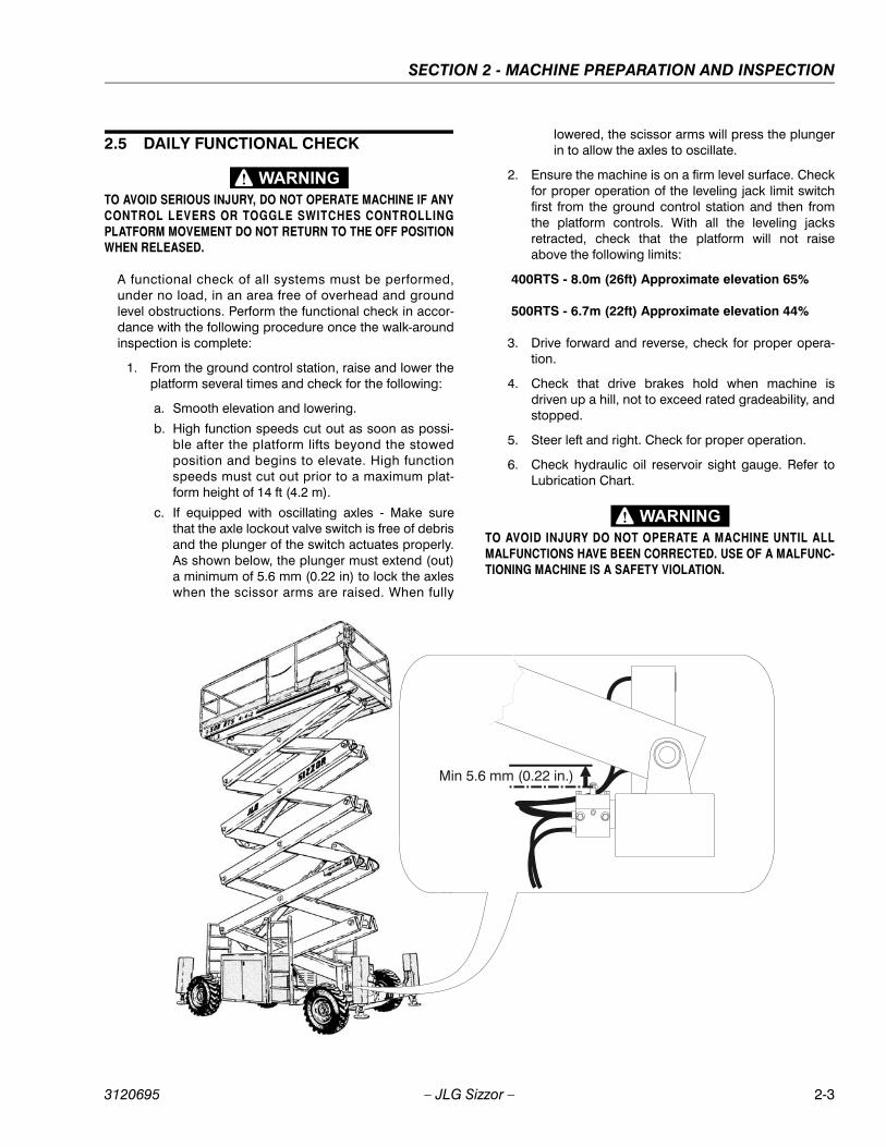
c. If equipped with oscillating axles - Make surethat the axle lockout valve switch is free of debrisand the plunger of the switch actuates properly.As shown below, the plunger must extend (out)a minimum of 5.6 mm (0.22 in) to lock the axleswhen the scissor arms are raised. When fully
lowered, the scissor arms will press the plungerin to allow the axles to oscillate.
2. Ensure the machine is on a firm level surface. Checkfor proper operation of the leveling jack limit switchfirst from the ground control station and then fromthe platform controls. With all the leveling jacksretracted, check that the platform will not raiseabove the following limits:
400RTS - 8.0m (26ft) Approximate elevation 65%
500RTS - 6.7m (22ft) Approximate elevation 44%
3. Drive forward and reverse, check for proper opera-tion.
4. Check that drive brakes hold when machine isdriven up a hill, not to exceed rated gradeability, andstopped.
5. Steer left and right. Check for proper operation.
6. Check hydraulic oil reservoir sight gauge. Refer toLubrication Chart.
TO AVOID INJURY DO NOT OPERATE A MACHINE UNTIL ALLMALFUNCTIONS HAVE BEEN CORRECTED. USE OF A MALFUNC-TIONING MACHINE IS A SAFETY VIOLATION.
Min 5.6 mm (0.22 in.)
SECTION 2 - MACHINE PREPARATION AND INSPECTION
2-4 – JLG Sizzor – 3120695
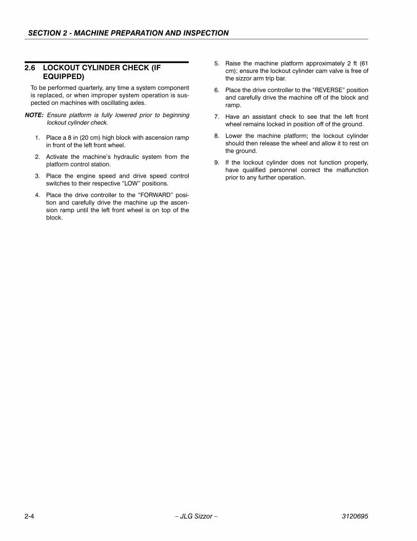
2.6 LOCKOUT CYLINDER CHECK (IF EQUIPPED)
To be performed quarterly, any time a system componentis replaced, or when improper system operation is sus-pected on machines with oscillating axles.
NOTE: Ensure platform is fully lowered prior to beginninglockout cylinder check.
1. Place a 8 in (20 cm) high block with ascension rampin front of the left front wheel.
2. Activate the machine’s hydraulic system from theplatform control station.
3. Place the engine speed and drive speed controlswitches to their respective “LOW” positions.
4. Place the drive controller to the “FORWARD” posi-tion and carefully drive the machine up the ascen-sion ramp until the left front wheel is on top of theblock.
5. Raise the machine platform approximately 2 ft (61cm); ensure the lockout cylinder cam valve is free ofthe sizzor arm trip bar.
6. Place the drive controller to the “REVERSE” positionand carefully drive the machine off of the block andramp.
7. Have an assistant check to see that the left frontwheel remains locked in position off of the ground.
8. Lower the machine platform; the lockout cylindershould then release the wheel and allow it to rest onthe ground.
9. If the lockout cylinder does not function properly,have qualified personnel correct the malfunctionprior to any further operation.

SECTION 2 - MACHINE PREPARATION AND INSPECTION
3120695 – JLG Sizzor – 2-5
Figure 2-1. Daily Walk-Around Inspection Diagram
SECTION 2 - MACHINE PREPARATION AND INSPECTION
2-6 – JLG Sizzor – 3120695
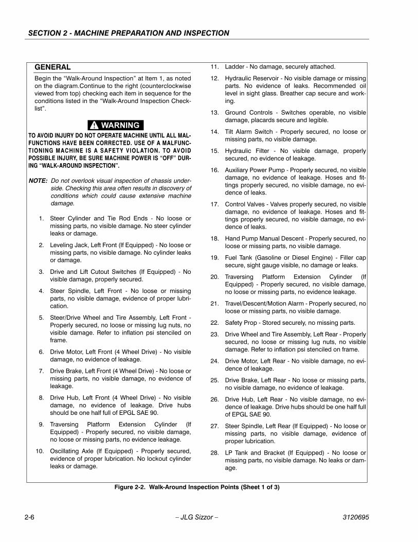
GENERALBegin the “Walk-Around Inspection” at Item 1, as notedon the diagram.Continue to the right (counterclockwiseviewed from top) checking each item in sequence for theconditions listed in the “Walk-Around Inspection Check-list”.
TO AVOID INJURY DO NOT OPERATE MACHINE UNTIL ALL MAL-FUNCTIONS HAVE BEEN CORRECTED. USE OF A MALFUNC-TIONING MACHINE IS A SAFETY VIOLATION. TO AVOIDPOSSIBLE INJURY, BE SURE MACHINE POWER IS “OFF” DUR-ING “WALK-AROUND INSPECTION”.
NOTE: Do not overlook visual inspection of chassis under-side. Checking this area often results in discovery ofconditions which could cause extensive machinedamage.
1. Steer Cylinder and Tie Rod Ends - No loose ormissing parts, no visible damage. No steer cylinderleaks or damage.
2. Leveling Jack, Left Front (If Equipped) - No loose ormissing parts, no visible damage. No cylinder leaksor damage.
3. Drive and Lift Cutout Switches (If Equipped) - Novisible damage, properly secured.
4. Steer Spindle, Left Front - No loose or missingparts, no visible damage, evidence of proper lubri-cation.
5. Steer/Drive Wheel and Tire Assembly, Left Front -Properly secured, no loose or missing lug nuts, novisible damage. Refer to inflation psi stenciled onframe.
6. Drive Motor, Left Front (4 Wheel Drive) - No visibledamage, no evidence of leakage.
7. Drive Brake, Left Front (4 Wheel Drive) - No loose ormissing parts, no visible damage, no evidence ofleakage.
8. Drive Hub, Left Front (4 Wheel Drive) - No visibledamage, no evidence of leakage. Drive hubsshould be one half full of EPGL SAE 90.
9. Traversing Platform Extension Cylinder (IfEquipped) - Properly secured, no visible damage,no loose or missing parts, no evidence leakage.
10. Oscillating Axle (If Equipped) - Properly secured,evidence of proper lubrication. No lockout cylinderleaks or damage.
11. Ladder - No damage, securely attached.
12. Hydraulic Reservoir - No visible damage or missingparts. No evidence of leaks. Recommended oillevel in sight glass. Breather cap secure and work-ing.
13. Ground Controls - Switches operable, no visibledamage, placards secure and legible.
14. Tilt Alarm Switch - Properly secured, no loose ormissing parts, no visible damage.
15. Hydraulic Filter - No visible damage, properlysecured, no evidence of leakage.
16. Auxiliary Power Pump - Properly secured, no visibledamage, no evidence of leakage. Hoses and fit-tings properly secured, no visible damage, no evi-dence of leaks.
17. Control Valves - Valves properly secured, no visibledamage, no evidence of leakage. Hoses and fit-tings properly secured, no visible damage, no evi-dence of leaks.
18. Hand Pump Manual Descent - Properly secured, noloose or missing parts, no visible damage.
19. Fuel Tank (Gasoline or Diesel Engine) - Filler capsecure, sight gauge visible, no damage or leaks.
20. Traversing Platform Extension Cylinder (IfEquipped) - Properly secured, no visible damage,no loose or missing parts, no evidence leakage.
21. Travel/Descent/Motion Alarm - Properly secured, noloose or missing parts, no visible damage.
22. Safety Prop - Stored securely, no missing parts.
23. Drive Wheel and Tire Assembly, Left Rear - Properlysecured, no loose or missing lug nuts, no visibledamage. Refer to inflation psi stenciled on frame.
24. Drive Motor, Left Rear - No visible damage, no evi-dence of leakage.
25. Drive Brake, Left Rear - No loose or missing parts,no visible damage, no evidence of leakage.
26. Drive Hub, Left Rear - No visible damage, no evi-dence of leakage. Drive hubs should be one half fullof EPGL SAE 90.
27. Steer Spindle, Left Rear (If Equipped) - No loose ormissing parts, no visible damage, evidence ofproper lubrication.
28. LP Tank and Bracket (If Equipped) - No loose ormissing parts, no visible damage. No leaks or dam-age.
Figure 2-2. Walk-Around Inspection Points (Sheet 1 of 3)

SECTION 2 - MACHINE PREPARATION AND INSPECTION
3120695 – JLG Sizzor – 2-7
29. Leveling Jack, Left Rear (If Equipped) - No loose ormissing parts, no visible damage. No cylinder leaksor damage.
30. Drive and Lift Cutout Switches (If Equipped) - Novisible damage, properly secured.
31. Battery Installation (Gasoline or Diesel Engine) -Proper electrolyte level, cables secure, no damageor corrosion. Holddowns secure.
32. Ladder - No damage, securely attached.
33. Traversing Platform (If Equipped) - No loose ormissing parts, no visible damage, platform deckextension operates properly.
34. Leveling Jack, Right Rear (If Equipped) - No looseor missing parts, no visible damage. No cylinderleaks or damage.
35. Drive and Lift Cutout Switches (If Equipped) - Novisible damage, properly secured.
36. Rear Steer Cylinder and Tie Rod Ends (If Equipped)- No loose or missing parts, no visible damage. Nosteer cylinder leaks or damage.
37. LP Tank and Bracket (If Equipped) - No loose ormissing parts, no visible damage. No leaks or dam-age.
38. Steer Spindle, Right Rear (If Equipped) - No looseor missing parts, no visible damage, evidence ofproper lubrication.
39. Drive Wheel and Tire Assembly, Left Rear - Properlysecured no loose or missing lug nuts, no visibledamage. Refer to inflation psi stenciled on frame.
40. Drive Motor, Right Rear - No visible damage, no evi-dence of leakage.
41. Drive Brake, Right Rear - No loose or missing parts,no visible damage, no evidence of leakage.
42. Drive Hub, Right Rear - No visible damage, no evi-dence of leakage. Drive hubs should be one halffull of EPGL SAE 90.
43. Safety Prop - Stored securely, no missing parts.
44. Traversing Platform Extension Cylinder (IfEquipped) - Properly secured, no visible damage,no loose or missing parts, no evidence leakage.
45. Engine Installation - Engine oil to full mark on dip-stick, oil fillercap secure. Muffler/exhaust systemproperly secured, no leakage. Air filter assemblysecure, no loose or missing parts, element clean.Gasoline Engine Only - Radiator cap secure, cool-ant to correct level.
46. Hydraulic Pump - Pump properly secured, no visi-ble damage, no evidence of leakage. Hoses and fit-tings properly secured, no visible damage, noevidence of leaks.
47. Handrail installation - All railings securely attached,no damage or missing parts, chains securelyattached.
48. Sizzor Arms and Sliding Wear Pads - Properlysecured, no visible damage, evidence of properlubrication. Inspect sizzor arm guards for damageand proper installation.
49. Ladder - No damage, securely attached.
50. Lift Cylinder - Properly secured, no visible damage,no loose or missing parts, no evidence leakage.
51. Traversing Platform Extension Cylinder (IfEquipped) - Properly secured, no visible damage,no loose or missing parts, no evidence of leakage.
52. Steer/Drive Wheel and Tire Assembly, Right Front -Properly secured, no loose or missing lug nuts, novisible damage. Refer to inflation psi stenciled onframe.
53. Drive Motor, Right Front (4 Wheel Drive) - No visibledamage, no evidence of leakage.
54. Drive Brake, Right Front (4 Wheel Drive) - No looseor missing parts, no visible damage, no evidence ofleakage.
55. Drive Hub, Right Front (4 Wheel Drive) - No visibledamage, no evidence of leakage. Drive hubsshould be one half full of EPGL SAE 90.
56. Steer Spindle, Right Front - No loose or missingparts, no visible damage, evidence of proper lubri-cation.
57. High Speed Limit Switch - No visible damage, prop-erly secured.
58. Platform Controls - Properly secured, no loose ormissing parts, no visible damage. Placards secureand legible, control switches return to neutral. Con-trol markings legible, manual in manual storagebox.
59. Leveling Jack, Right Front (If Equipped) - No looseor missing parts, no visible damage. No cylinderleaks or damage.
60. Drive and Lift Cutout Switches (If Equipped) - Novisible damage, properly secured.
61. Traversing Platform (If Equipped) - No loose ormissing parts, no visible damage, platform deckextension operates properly.
Figure 2-3. Walk-Around Inspection Points (Sheet 2 of 3)
SECTION 2 - MACHINE PREPARATION AND INSPECTION
2-8 – JLG Sizzor – 3120695
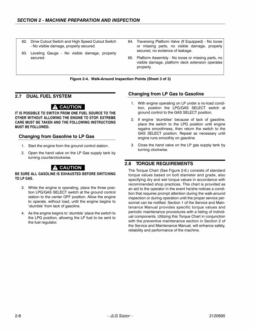
2.7 DUAL FUEL SYSTEM
IT IS POSSIBLE TO SWITCH FROM ONE FUEL SOURCE TO THEOTHER WITHOUT ALLOWING THE ENGINE TO STOP. EXTREMECARE MUST BE TAKEN AND THE FOLLOWING INSTRUCTIONSMUST BE FOLLOWED.
Changing from Gasoline to LP Gas
1. Start the engine from the ground control station.
2. Open the hand valve on the LP Gas supply tank byturning counterclockwise.
BE SURE ALL GASOLINE IS EXHAUSTED BEFORE SWITCHINGTO LP GAS.
3. While the engine is operating, place the three posi-tion LPG/GAS SELECT switch at the ground controlstation to the center OFF position. Allow the engineto operate, without load, until the engine begins to‘stumble’ from lack of gasoline.
4. As the engine begins to ‘stumble’ place the switch tothe LPG position, allowing the LP fuel to be sent tothe fuel regulator.
Changing from LP Gas to Gasoline
1. With engine operating on LP under a no-load condi-tion, position the LPG/GAS SELECT switch atground control to the GAS SELECT position.
2. If engine ‘stumbles’ because of lack of gasoline,place the switch to the LPG position until engineregains smoothness, then return the switch to theGAS SELECT position. Repeat as necessary untilengine runs smoothly on gasoline.
3. Close the hand valve on the LP gas supply tank byturning clockwise.
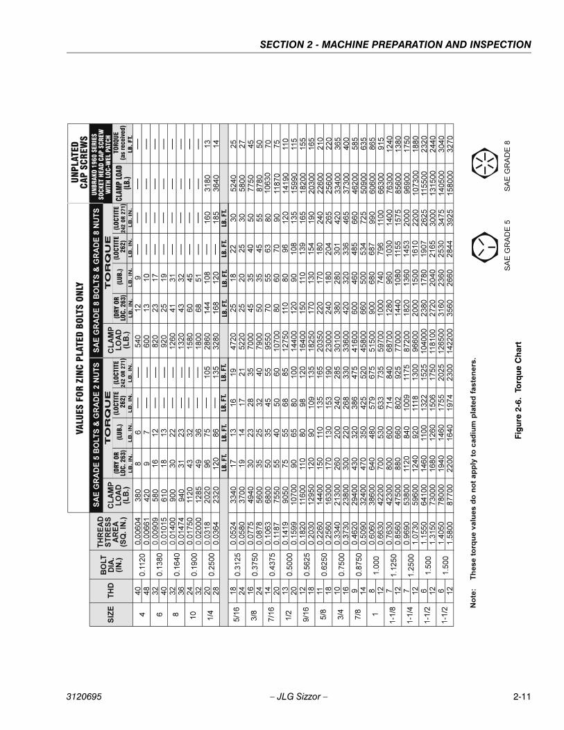
2.8 TORQUE REQUIREMENTSThe Torque Chart (See Figure 2-6.) consists of standardtorque values based on bolt diameter and grade, alsospecifying dry and wet torque values in accordance withrecommended shop practices. This chart is provided asan aid to the operator in the event he/she notices a condi-tion that requires prompt attention during the walk-aroundinspection or during operation until the proper service per-sonnel can be notified. Section 1 of the Service and Main-tenance Manual provides specific torque values andperiodic maintenance procedures with a listing of individ-ual components. Utilizing this Torque Chart in conjunctionwith the preventive maintenance section in Section 2 ofthe Service and Maintenance Manual, will enhance safety,reliability and performance of the machine.
62. Drive Cutout Switch and High Speed Cutout Switch- No visible damage, properly secured.
63. Leveling Gauge - No visible damage, properlysecured.
64. Traversing Platform Valve (If Equipped) - No looseor missing parts, no visible damage, properlysecured, no evidence of leakage.
65. Platform Assembly - No loose or missing parts, novisible damage, platform deck extension operatesproperly.
Figure 2-4. Walk-Around Inspection Points (Sheet 3 of 3)

SECTION 2 - MACHINE PREPARATION AND INSPECTION
3120695 – JLG Sizzor – 2-9
Figu
re 2
-5.
Lubr
icat
ion
Dia
gram

SECTION 2 - MACHINE PREPARATION AND INSPECTION
2-10 – JLG Sizzor – 3120695
Table 2-1. Lubrication Chart
INDEX NO COMPONENT NUMBER/TYPE LUBE POINTS LUBE METHOD INTERVAL
HOURS
1 Oscillating Axle Pivot Point (Optional) 1 Grease Fitting MPG - Pressure Gun 1002 Lockout Cylinders (Optional) 2 Grease Fittings (1 each cylinder) MPG - Pressure Gun 1003 Front Steering Spindles (2-W/D) 2 Grease Fittings MPG - Pressure Gun 1004 Front Steering Spindles (4-W/D)
(Optional)2 Grease Fittings MPG - Pressure Gun 100
5 Tow Bar Hitch (Optional) 1 Grease Fitting MPG - Pressure Gun 1006 Wheel Bearings (2-W/D) N/A MPG - Repack 20007 *Wheel Drive Hub (4-W/D) (Optional) Fill Plug EPGL (SAE 90) 5008 Hydraulic Oil Reservoir Fill Cap/Drain Plug HO - Check HO Level (See note 4)/
HO - Change HO10/500
9 ** Hydraulic Filter Element N/A Initial Change - 40 Hours 25010 *Wheel Drive Hub Fill Plug EPGL (SAE 90) 50011 Rear Steering Spindles (4-W/S)
(Optional)2 Grease Fittings MPG - Pressure Gun 100
12 400 RTS Sizzor Arm Pivot Pins500 RTS Sizzor Arm Pivot Pins
30 Grease Fittings (400 RTS)38 Grease Fittings (500RTS)
MPG - Pressure GunMPG - Pressure Gun
100
13 Rail Slides N/A MPG - Brush 10014 Platform Extension Slides (Optional) N/A MPG - Brush 10015 Lift Cylinder 4 Grease Fittings MPG - Pressure Gun 10016 Engine Crankcase Fill Cap/Drain Plug Check Engine Oil Level 10/100
*Torque Hubs should be 1/2 full of lubricant
** JLG Industries recommends replacing the hydraulicfilter after the first 40 hours of operation and every 250hours thereafter.
KEY TO LUBRICANTS:
MPG - Multi-purpose Grease
EPGL - Extreme Pressure Gear Lube
HO - Hydraulic Oil (Mobil 424)
TO AVOID PERSONAL INJURY, USE SAFETY PROP FOR ALLMAINTENANCE REQUIRING PLATFORM TO BE ELEVATED.
NOTE: 1. Be sure to lubricate like items on each side2. Recommended lubricating intervals are basedon machine operations under normal conditions.For machines used in multi-shift operations and/orexposed to hostile environments or conditions,lubrication frequencies must be increased accord-ingly.3. Operate hydraulic functions through one com-plete cycle before checking hydraulic oil level intank. Oil should be visible in ADD sight window onhydraulic tank. If oil is not visible, add oil until oil isvisible in both ADD and FULL sight windows ontank. Do not overfill tank.4. Any time the pump coupling is removed, coatsplines of coupling with Texaco Code 1912 greaseprior to assembly. (gasoline or diesel engine only).
SECTION 2 - MACHINE PREPARATION AND INSPECTION
3120695 – JLG Sizzor – 2-11
Figu
re 2
-6.
Torq
ue C
hart
SECTION 2 - MACHINE PREPARATION AND INSPECTION
2-12 – JLG Sizzor – 3120695
This page intentionally left blank.

SECTION 3 - USER RESPONSIBILITIES AND MACHINE CONTROL
3120695 – JLG Sizzor – 3-1
SECTION 3. USER RESPONSIBILITIES AND MACHINE CONTROL
3.1 GENERAL
SINCE THE MANUFACTURER HAS NO DIRECT CONTROL OVERMACHINE APPLICATION AND OPERATION, CONFORMANCE WITHGOOD SAFETY PRACTICES IN THESE AREAS IS THE RESPONSI-BILITY OF THE USER AND HIS OPERATING PERSONNEL.
This section provides the necessary information neededto understand control functions. Included in this sectionare the operating characteristics and limitations, and func-tions and purposes of controls and indicators. It is impor-tant that the user read and understand the properprocedures before operating the machine. These proce-dures will aid in obtaining optimum service life and safeoperation.
3.2 PERSONNEL TRAINING
The sizzor lift is a personnel handling device; therefore, itis essential that it be operated and maintained only byauthorized personnel who have demonstrated that theyunderstand the proper use and maintenance of themachine. It is important that all personnel who areassigned to and responsible for the operation and mainte-nance of the machine undergo a thorough training pro-gram and check out period in order to become familiarwith the characteristics prior to operating the machine.
In addition, personnel operating the machine should befamiliar with ANSI standard A92.6-1999 Responsibilities.This standard contains sections outlining the responsibili-ties of the owners, users, operators, lessors and lesseesconcerning safety, training, inspection, maintenance,application and operation.
Persons under the influence of drugs or alcohol or whoare subject to seizures, dizziness or loss of physical con-trol must not be permitted to operate the machine.
Operator Training
Operator training must include instruction in the following:
1. Use and limitations of the platform controls, groundcontrols, emergency controls and safety systems.
2. Knowledge and understanding of this manual and ofthe control markings, instructions and warnings onthe machine itself.
3. Knowledge and understanding of all safety workrules of the employer and of Federal, State andLocal Statutes, including training in the recognitionand avoidance of potential hazards in the workplace; with particular attention to the work to be per-formed.
4. Proper use of all required personnel safety equip-ment.
5. Sufficient knowledge of the mechanical operation ofthe machine to recognize a malfunction or potentialmalfunction.
6. The safest means to operate near overhead obstruc-tions, other moving equipment, obstacles, depres-sions, holes, dropoffs, etc. on the supportingsurface.
7. Means to avoid the hazards of unprotected electricalconductors.
8. Any other requirements of a specific job or machineapplication.
Training Supervision
Training must be done under the supervision of a qualifiedoperator or supervisor in an open area free of obstructionsuntil the trainee has developed the ability to safely controla sizzor lift in congested work locations.
Operator Responsibility
The operator must be instructed that he has the responsi-bility and authority to shut down the machine in case of amalfunction or other unsafe condition of either themachine or the job site and to request further informationfrom his supervisor or JLG Distributor before proceeding.
NOTE: Manufacturer or Distributor will provide qualified per-sons for training assistance with first unit(s) deliveredand thereafter as requested by user or his person-nel.
3.3 OPERATING CHARACTERISTICS AND LIMITATIONS
General
A thorough knowledge of the operating characteristicsand limitations of the machine is always the first require-ment for any user, regardless of user’s experience withsimilar types of equipment.

SECTION 3 - USER RESPONSIBILITIES AND MACHINE CONTROL
3-2 – JLG Sizzor – 3120695
Placards
Important points to remember during operation are pro-vided at the control stations by DANGER, WARNING,CAUTION, IMPORTANT and INSTRUCTION placards. Thisinformation is placed at various locations for the expresspurpose of alerting personnel of potential hazards consti-tuted by the operating characteristics and load limitationsof the machine. See foreword for definitions of the aboveplacards.
Capacities
Raising platform above stowed position with or withoutany load in platform, is based on the following criteria:
1. Machine is positioned on a smooth, firm and levelsurface.
2. Load is within manufacturer’s rated capacity.
3. All machine systems are functioning properly.
4. Leveling Jacks properly set (If Equipped).
StabilityThis machine, as originally manufactured by JLG andoperated within its rated capacity on a smooth, firm andlevel supporting surface, provides a stable aerial platformfor all platform positions.
3.4 CONTROLS AND INDICATORSMachines are equipped with control panels that use sym-bols instead of words to indicate control functions. Referto Figure 3-3., Control Panel Symbols for these symbolsand their corresponding functions.
Ground Control Station
DO NOT OPERATE FROM GROUND CONTROL STATION WITHPERSONNEL IN THE PLATFORM EXCEPT IN AN EMERGENCY.
PERFORM AS MANY PRE-OPERATIONAL CHECKS AND INSPEC-TIONS FROM THE GROUND CONTROL STATION AS POSSIBLE.
Figure 3-1. Ground Control Station

SECTION 3 - USER RESPONSIBILITIES AND MACHINE CONTROL
3120695 – JLG Sizzor – 3-3
1. Ignition/Emergency Stop - A two-position, redmushroom shaped switch supplies electrical powerto the Start button when positioned up. When posi-tioned down, the switch shuts off electrical power tothe ignition circuit, acting as an emergency stopswitch.With the MAIN POWER switch in the OFFposition, the key can be removed in order to inca-pacitate the machine on the jobsite to avoid unau-thorized use of the machine.
2. Power Selector Switch - A three position key-oper-ated power selector switch supplies operatingpower to the platform or ground controls, asselected. When positioned to platform, the switchprovides power to the platform controls. When posi-tioned to ground, the switch provides power to theground controls. With the power selector switch inthe center off position, power is shut off to both plat-form and ground controls.
NOTE: With the PLATFORM/GROUND SELECT switchpositioned to GROUND, engine speed will stay inLOW at all times.
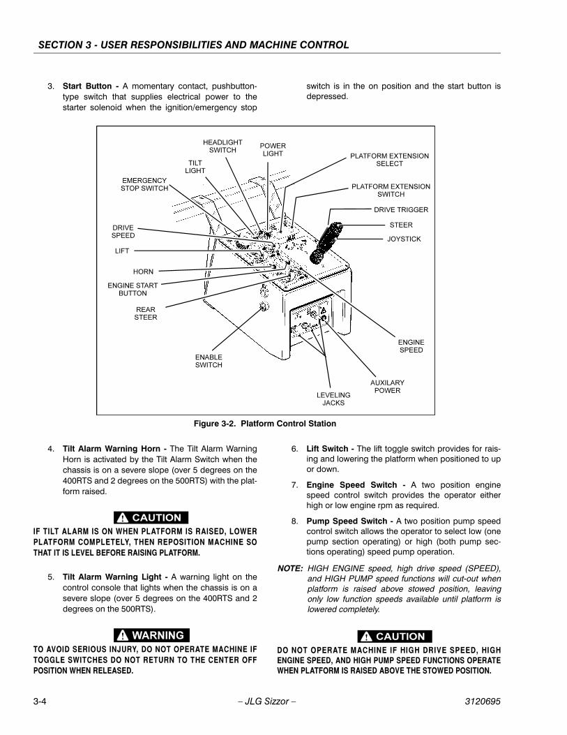
3. Start Button - A momentary contact, pushbutton-type switch that supplies electrical power to thestarter solenoid when the IGNITION/EMERGENCYSTOP switch is in the ON position and the STARTbutton is depressed.
4. Lift Switch - A three position, momentary contact liftcontrol switch provides raising and lowering of theplatform when positioned to UP or down.
5. High Engine Circuit Breaker (Diesel Engine) - Apush button reset 3 Amp circuit breaker located onground control panel returns interrupted power todiesel engine throttle when depressed.
6. Start Button - A momentary contact, push-buttontype switch supplies electrical power to the startersolenoid when the IGNITION switch is positioned upand the START button is depressed.
7. Choke Switch (If Equipped) - A momentary con-tact, push-button type switch supplies power to thechoke solenoid, when depressed, to assist cold startoperation.
8. Platform Traversing Switch (If Equipped) - A dou-ble throw, momentary contact toggle-type platformtraversing switch permits the operator to hydrauli-cally extend and retract the platform extension asneeded for “up and over” work access.
9. Platform Traversing Select Switch (If Equipped) -A full throw, momentary contact toggle-type plat-form traversing select switch that works simulta-neously with the platform traversing switch topermits the operator to hydraulically extend and
retract the rear platform extension as needed for “upand over” work access.
10. Gasoline/LPG Select Switch (Duel Fuel Only) - Athree position toggle-type switch is used to selectthe desired method of powering the unit. Placing theswitch in the gasoline position shuts off the fuel flowfrom the lp gas supply tank and allows fuel flow fromthe gasoline tank. Moving the switch to the lpg posi-tion shuts off fuel flow from the gasoline tank andallows lp gas from supply tank to be used to powerthe unit. With the switch in the center position, fuelflow is restricted from both supply tanks.
11. Hourmeter - The hourmeter records engine or elec-tric motor operating time.
12. Voltmeter - With the emergency stop switch in theup position, and before starting the engine, the volt-meter indicates output voltage of the alternator. Nor-mal reading for the voltmeter will be 12-14 volts witha properly charged or charging battery.
13. Water Temperature Gauge - The water temperaturegauge provides a visual display of the engine cool-ant temperature.
14. Oil Pressure Gauge - The oil pressure gauge dis-plays the engine lubrication system operating pres-sure.
Platform Control Station
1. Enable Switch - These machines are equipped withan enable switch on the side of the platform controlconsole. On machines built with a serial numberbefore 0200058922, the enable switch must bepressed before activating the drive, lift or steer func-tions. A built-in timer shuts off power to these func-tions if they are not activated within 3 seconds afterthe enable switch is depressed. In addition, thistimer will shut off power to the drive and lift functions3 seconds after they are deactivated, making if nec-essary to depress the enable switch before activat-ing drive and lift again. The steer function, unlessactivated in conjunction with the drive or lift func-tions, will automatically cut off after 3 seconds ofoperation. On machines built from, and including,serial number 0200058922, the enable switch mustbe depressed and held for the duration of lift. Theenable switch works in conjunction with the liftswitch only.
2. Ignition/Emergency Stop Switch - An ignition/emergency stop red mushroom-type switch is pro-vided in order to turn on machine power in the plat-form and also to turn off machine power in the eventof an emergency. Power is turned on by positioningthe switch to the up (on) position, and is turned offby positioning the switch to the down (off) position.
SECTION 3 - USER RESPONSIBILITIES AND MACHINE CONTROL
3-4 – JLG Sizzor – 3120695
3. Start Button - A momentary contact, pushbutton-type switch that supplies electrical power to thestarter solenoid when the ignition/emergency stop
switch is in the on position and the start button isdepressed.
4. Tilt Alarm Warning Horn - The Tilt Alarm WarningHorn is activated by the Tilt Alarm Switch when thechassis is on a severe slope (over 5 degrees on the400RTS and 2 degrees on the 500RTS) with the plat-form raised.
IF TILT ALARM IS ON WHEN PLATFORM IS RAISED, LOWERPLATFORM COMPLETELY, THEN REPOSITION MACHINE SOTHAT IT IS LEVEL BEFORE RAISING PLATFORM.
5. Tilt Alarm Warning Light - A warning light on thecontrol console that lights when the chassis is on asevere slope (over 5 degrees on the 400RTS and 2degrees on the 500RTS).
TO AVOID SERIOUS INJURY, DO NOT OPERATE MACHINE IFTOGGLE SWITCHES DO NOT RETURN TO THE CENTER OFFPOSITION WHEN RELEASED.
6. Lift Switch - The lift toggle switch provides for rais-ing and lowering the platform when positioned to upor down.
7. Engine Speed Switch - A two position enginespeed control switch provides the operator eitherhigh or low engine rpm as required.
8. Pump Speed Switch - A two position pump speedcontrol switch allows the operator to select low (onepump section operating) or high (both pump sec-tions operating) speed pump operation.
NOTE: HIGH ENGINE speed, high drive speed (SPEED),and HIGH PUMP speed functions will cut-out whenplatform is raised above stowed position, leavingonly low function speeds available until platform islowered completely.
DO NOT OPERATE MACHINE IF HIGH DRIVE SPEED, HIGHENGINE SPEED, AND HIGH PUMP SPEED FUNCTIONS OPERATEWHEN PLATFORM IS RAISED ABOVE THE STOWED POSITION.
Figure 3-2. Platform Control Station

SECTION 3 - USER RESPONSIBILITIES AND MACHINE CONTROL
3120695 – JLG Sizzor – 3-5
9. PQ Controller - The PQ Controller performs threefunctions: Drive, Steer and Drive Speed. On allmachines built before serial number 0200058922,tilting the controller in the direction you want to go(forward or reverse) activates drive in that direction.The thumb-operated steer switch on top of the con-troller handle activates the steer wheels in the direc-tion it is moved. If machine is equipped with fourwheel steer, this switch operates only the front steerwheels. On all machines built after, and including,serial number 0200058922 there is a red triggerswitch on the front of the controller. This switch mustbe depressed and held in order to drive themachine.
10. Auxiliary Power (If Equipped) - A toggle type auxil-iary power control switch energizes the electrically-operated hydraulic pump, when actuated. Switchmust be held ON for the duration of auxiliary pumpuse.
The auxiliary power pump functions to provide sufficientoil flow to operate the Traversing Platform Extensionsshould the main pump or engine fail during operation.
It should be noted that the functions will operate at aslower than normal rate because of the lower GPM deliv-ered.
NOTE: Auxiliary power pump only operates the TraversingPlatform Extensions.
11. Platform Traversing Switch (If Equipped) - This isa double throw, momentary contact toggle-typeswitch which permits the operator to hydraulicallyextend and retract the platforms as needed for “upand over” work access.
12. Platform Traversing Select Switch (If Equipped) -In order to select the platform to traverse there is afull throw, momentary contact toggle-type platformtraversing select switch, that works in conjunctionwith the platform traversing switch to permit theoperator to hydraulically extend and retract the plat-forms as needed for “up and over” work access.
13. Travel Warning Horn - A push-button type hornswitch supplies electrical power to an audible warn-ing device when pressed.
14. Choke (If Equipped) - A push-button type switchsupplies power, when depressed, to the choke sole-noid for cold start operations.
15. Leveling Jacks (If Equipped) - The four momentarycontact type toggle switches correspond to the fourleveling jacks, one at each corner of the machine.
BE AWARE OF OTHER PERSONNEL AND EQUIPMENT WHENEXTENDING OR RETRACTING LEVELING JACKS.
16. Engine Distress Light (Gasoline Engine) - Theengine distress light is connected to a sensor on theengine that detects when coolant temperature risesabove a preset level, illuminating the warning light.
17. Engine Distress Light (Diesel Engine) - Theengine distress light is connected to a sensor on theengine that detects when oil pressure falls below apreset level, illuminating the warning light

SECTION 3 - USER RESPONSIBILITIES AND MACHINE CONTROL
3-6 – JLG Sizzor – 3120695
Figure 3-3. Control Panel Symbols

SECTION 3 - USER RESPONSIBILITIES AND MACHINE CONTROL
3120695 – JLG Sizzor – 3-7
Figure 3-4. Decal Location - Right Side (Sheet 1 of 2)
SECTION 3 - USER RESPONSIBILITIES AND MACHINE CONTROL
3-8 – JLG Sizzor – 3120695
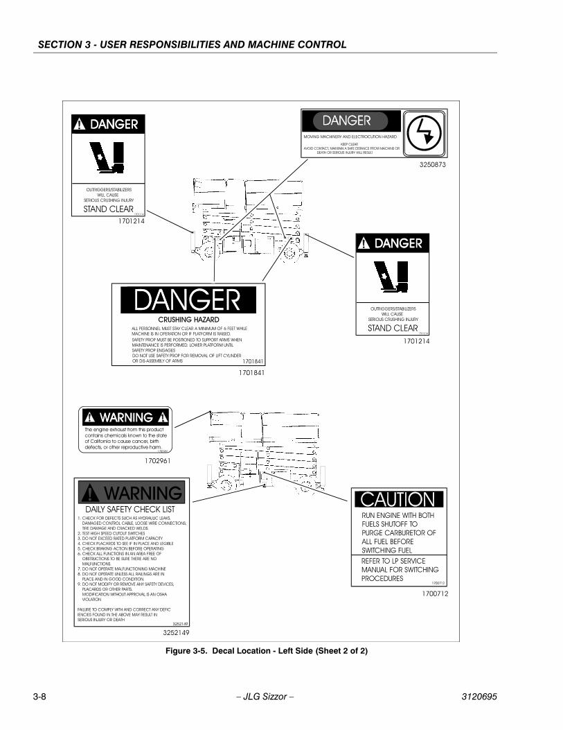
Figure 3-5. Decal Location - Left Side (Sheet 2 of 2)

SECTION 4 - MACHINE OPERATION
3120695 – JLG Sizzor – 4-1
SECTION 4. MACHINE OPERATION
4.1 DESCRIPTIONThis machine is a self-propelled elevating ‘sizzor’ aerialwork platform. The Sizzor Lift’s intended purpose is toposition personnel with their tools and supplies at posi-tions above ground level. The machine can be used toreach work areas located above machinery or equipment.
The JLG Sizzor Lift has a primary operator Control Stationin the platform. From this Control Station, the operator candrive and steer the machine in both forward and reversedirections as well as raise and lower the platform. Themachine has a Ground Control Station which will overridethe Platform Control Station. Ground Controls operate LiftUp, Lift Down, and Platform Traversing, (If Equipped). Thecontrols are to be used only for daily check or in an emer-gency to lower the platform to the ground should theoperator in the platform be unable to do so.
Instructions and hazard warnings are posted adjacent toboth operator control stations and at other places on themachine. It is extremely important that operators knowwhat instructions and warnings are placed on themachine, and review these periodically so that they arefresh in their minds. Vibrations emitted by these machinesare not hazardous to an operator in the work platform.
The JLG Sizzor Lift is designed to provide efficient andsafe operation when maintained and operated in accor-dance with warnings on the machine, the Operators &Safety, Service and Specification Manual and all jobsiteand government rules and regulations. As with any type ofmachinery, the operator is very important to efficient andsafe operation. Owner/user/operator must be familiar withSections 6, 7, 8, 9, and 10 of ANSI A92.6-1999. These sec-tions contain the responsibilities of the owner, users, oper-ators, lessors and lessees concerning safety, training,inspection, maintenance, application and operation. It isabsolutely necessary that the JLG Lift be regularly main-tained in accordance with this section and the Service andSpecifications section, and that any evidence of lack ofmaintenance, malfunction, excessive wear, damage ormodification to the machine be reported immediately tothe machine owner or the jobsite supervisor or safetymanager and that the machine be taken out of serviceuntil all discrepancies are corrected.
The JLG Sizzor Lift is not intended to be used to lift mate-rial other than supplies which personnel in the platformrequire to do their job. Supplies or tools which extend out-side the platform are prohibited. It must not be used as aforklift, crane, support for overhead structure, or to pushor pull another object.
The machine has a manual descent system which willallow the platform to lowered without power from theengine/motor powered pump.
The JLG Sizzor Lift is powered using hydraulic motors andcylinders for the various machine motions. The hydrauliccomponents are controlled by electrically activatedhydraulic valves using switches and the joystick controller.The machine is equipped with a Enable Switch whichmust be pressed before activating the DRIVE, LIFT orSTEER functions. The Enable Switch has a built-in timerwhich shuts off power to these functions if they are notactivated within 3 seconds after Enable Switch isdepressed. The speeds of functions controlled by the joy-stick controller are variable from zero to maximum speeddepending upon the position of the controller. Functionscontrolled by toggle switches are either on or off. Higheror lower speed is possible only when the applicable highfunction speed control switch at the Platform Control Sta-tion is used in conjunction with the drive function. Allswitches at the platform are guarded to prevent inadvert-ant operation by individual switch guards.
The JLG Sizzor is a two or four wheel drive machine withdrive power being supplied by a hydraulic motor for eachdrive wheel. Each drive wheel is supplied with a hydrauli-cally released, spring applied brake. The brakes are auto-matically applied anytime the Drive controller is returnedto the neutral position.
The capacities of model 400RTS and 500RTS are foundon the capacity decals located on the machine. Thesecapacities are based on a load uniformly distributed in thecenter of the platform. This means that the total combinedweight of personnel, tools and supplies must not exceedthe given capacity for a particular model.
The platform may be raised only when positioned on firm,level and uniform surfaces. Leveling jacks, if provided, areto assist in leveling the Sizzor Lift. The Sizzor Lift must belevel when operating on leveling jacks.
4.2 GENERAL
This section provides the necessary information neededto operate the machine. Included in this section are theprocedures for starting, stopping, traveling, steering, park-ing, platform loading and transporting. It is important thatthe user read and understand the proper proceduresbefore operating the machine.
Updated 4/19/00
SECTION 4 - MACHINE OPERATION
4-2 – JLG Sizzor – 3120695
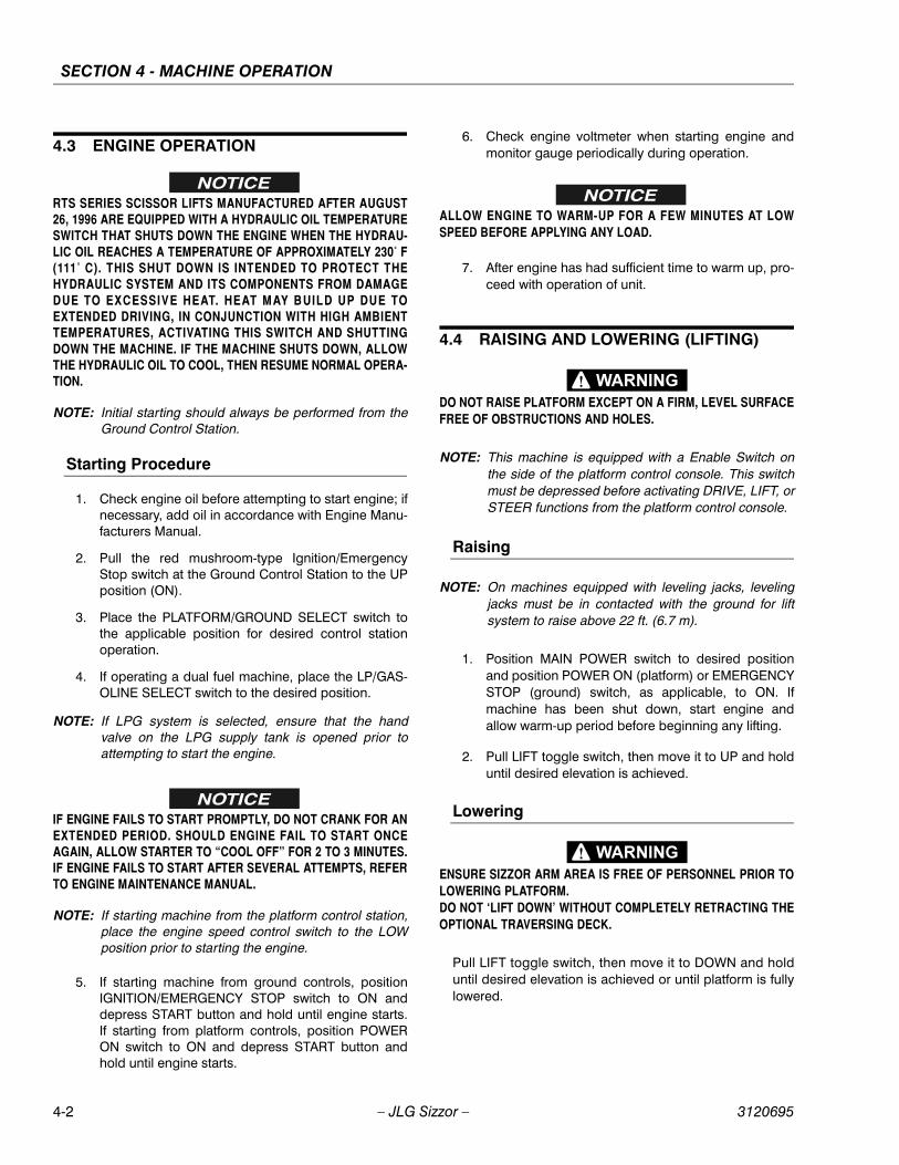
4.3 ENGINE OPERATION
RTS SERIES SCISSOR LIFTS MANUFACTURED AFTER AUGUST26, 1996 ARE EQUIPPED WITH A HYDRAULIC OIL TEMPERATURESWITCH THAT SHUTS DOWN THE ENGINE WHEN THE HYDRAU-LIC OIL REACHES A TEMPERATURE OF APPROXIMATELY 230˚ F(111˚ C). THIS SHUT DOWN IS INTENDED TO PROTECT THEHYDRAULIC SYSTEM AND ITS COMPONENTS FROM DAMAGEDUE TO EXCESSIVE HEAT. HEAT MAY BUILD UP DUE TOEXTENDED DRIVING, IN CONJUNCTION WITH HIGH AMBIENTTEMPERATURES, ACTIVATING THIS SWITCH AND SHUTTINGDOWN THE MACHINE. IF THE MACHINE SHUTS DOWN, ALLOWTHE HYDRAULIC OIL TO COOL, THEN RESUME NORMAL OPERA-TION.
NOTE: Initial starting should always be performed from theGround Control Station.
Starting Procedure
1. Check engine oil before attempting to start engine; ifnecessary, add oil in accordance with Engine Manu-facturers Manual.
2. Pull the red mushroom-type Ignition/EmergencyStop switch at the Ground Control Station to the UPposition (ON).
3. Place the PLATFORM/GROUND SELECT switch tothe applicable position for desired control stationoperation.
4. If operating a dual fuel machine, place the LP/GAS-OLINE SELECT switch to the desired position.
NOTE: If LPG system is selected, ensure that the handvalve on the LPG supply tank is opened prior toattempting to start the engine.
IF ENGINE FAILS TO START PROMPTLY, DO NOT CRANK FOR ANEXTENDED PERIOD. SHOULD ENGINE FAIL TO START ONCEAGAIN, ALLOW STARTER TO “COOL OFF” FOR 2 TO 3 MINUTES.IF ENGINE FAILS TO START AFTER SEVERAL ATTEMPTS, REFERTO ENGINE MAINTENANCE MANUAL.
NOTE: If starting machine from the platform control station,place the engine speed control switch to the LOWposition prior to starting the engine.
5. If starting machine from ground controls, positionIGNITION/EMERGENCY STOP switch to ON anddepress START button and hold until engine starts.If starting from platform controls, position POWERON switch to ON and depress START button andhold until engine starts.
6. Check engine voltmeter when starting engine andmonitor gauge periodically during operation.
ALLOW ENGINE TO WARM-UP FOR A FEW MINUTES AT LOWSPEED BEFORE APPLYING ANY LOAD.
7. After engine has had sufficient time to warm up, pro-ceed with operation of unit.
4.4 RAISING AND LOWERING (LIFTING)
DO NOT RAISE PLATFORM EXCEPT ON A FIRM, LEVEL SURFACEFREE OF OBSTRUCTIONS AND HOLES.
NOTE: This machine is equipped with a Enable Switch onthe side of the platform control console. This switchmust be depressed before activating DRIVE, LIFT, orSTEER functions from the platform control console.
Raising
NOTE: On machines equipped with leveling jacks, levelingjacks must be in contacted with the ground for liftsystem to raise above 22 ft. (6.7 m).
1. Position MAIN POWER switch to desired positionand position POWER ON (platform) or EMERGENCYSTOP (ground) switch, as applicable, to ON. Ifmachine has been shut down, start engine andallow warm-up period before beginning any lifting.
2. Pull LIFT toggle switch, then move it to UP and holduntil desired elevation is achieved.
Lowering
ENSURE SIZZOR ARM AREA IS FREE OF PERSONNEL PRIOR TOLOWERING PLATFORM.DO NOT ‘LIFT DOWN’ WITHOUT COMPLETELY RETRACTING THEOPTIONAL TRAVERSING DECK.
Pull LIFT toggle switch, then move it to DOWN and holduntil desired elevation is achieved or until platform is fullylowered.

SECTION 4 - MACHINE OPERATION
3120695 – JLG Sizzor – 4-3
4.5 TRAVERSING PLATFORM (OPTIONAL)
The machine may be equipped with hydraulically oper-ated traversing platforms that moves 4 ft. (1.2 meters) ateach end of the machine to give the operator “up andover” access to worksites. The traversing platform is oper-ated by either the TRAVERSE toggle switches at platformcontrol console or the TRAVERSE toggle switch at theground control switches.
TO AVOID INJURY TO GROUND PERSONNEL, RETRACT TRA-VERSING PLATFORM COMPLETELY BEFORE LOWERING PLAT-FORM.
4.6 STEERING
To steer the machine, the thumb operated steer controlswitch on the controller handle is positioned to the rightfor traveling right, or to the left for traveling left.
To steer the machine with the optional 4 wheel steer, posi-tion steer control switch to right for traveling right, or to leftfor traveling left.
When released, the switch will return to the center-off posi-tion and the wheels will remain in the previously selectedposition. To return the wheels to the straightened position,
the switch must be activated in the opposite direction untilthe wheels are centered.
4.7 TRAVELING (DRIVING)
ALWAYS RAISE LEVELING JACKS, IF EQUIPPED, BEFORE TRAV-ELING TO AVOID INJURY TO PERSONNEL OR DAMAGE TOMACHINE.
IF EQUIPPED WITH LEVELING JACKS, DRIVE FUNCTION IS CUTOUT WHEN LEVELING JACKS ARE IN THE SET POSITION.
IF MACHINE BECOMES STUCK DURING TRAVEL, DO NOT“ROCK” MACHINE IN AN ATTEMPT TO REGAIN TRACTION, ASDAMAGE TO DRIVE HUBS MAY RESULT.
DO NOT DRIVE WITH PLATFORM RAISED EXCEPT ON ASMOOTH, FIRM, AND LEVEL SURFACE FREE OF OBSTRUCTIONSAND HOLES.
TO AVOID LOSS OF CONTROL OR UPSET ON GRADES ANDSIDESLOPES, DO NOT DRIVE MACHINE ON GRADES OR SIDES-LOPES EXCEEDING THOSE SPECIFIED FOR THE MACHINE.TRAVEL GRADES AND SIDESLOPES WITH PLATFORM COM-PLETELY LOWERED.
Figure 4-1. Grade and Sideslope

SECTION 4 - MACHINE OPERATION
4-4 – JLG Sizzor – 3120695
TRAVEL GRADES IN “LOW” DRIVE SPEED ONLY. USE EXTREMECAUTION WHEN DRIVING IN REVERSE AND AT ALL TIMES WHENDRIVING WITH PLATFORM ELEVATED AND ESPECIALLY WHENDRIVING WITH ANY PART OF MACHINE WITHIN 6 FEET (2 M) OFAN OBSTRUCTION.HIGH DRIVE SPEED IS CUT OUT WHEN PLATFORM IS RAISEDABOVE STOWED POSITION. IF LIMIT SWITCH MALFUNCTIONS,SHUT DOWN MACHINE AND HAVE AUTHORIZED SERVICE PER-SONNEL REPAIR OR REPLACE LIMIT SWITCH PRIOR TO RESUM-ING OPERATION.THE 400RTS MAY BE EQUIPPED WITH A 5 DEGREES TILTSWITCH THAT ILLUMINATES A LIGHT ON THE PLATFORM CON-TROL CONSOLE AND SOUNDS AN AUDIBLE ALARM WHEN THEMACHINE IS ON A SLOPE (OVER 5 DEGREES) WITH THE PLAT-FORM RAISED.THE 500RTS IS EQUIPPED WITH A 2 DEGREES TILT SWITCHTHAT ILLUMINATES A LIGHT ON THE PLATFORM CONTROLCONSOLE AND SOUNDS AN AUDIBLE ALARM WHEN THEMACHINE IS ON A SLOPE (OVER 2 DEGREES) WITH THE PLAT-FORM RAISED. WHEN MACHINE IS ON A SLOPE (OVER 2DEGREES) WITH THE PLATFORM COMPLETELY LOWERED,ONLY THE WARNING LIGHT IS ILLUMINATED.
Traveling Forward
NOTE: On machines equipped with leveling jacks, levelingjacks must be in the stowed position before opera-tion of the drive system.
1. Position ignition/emergency stop switch to on. Ifmachine has been shut down, start engine andallow warm-up period before beginning any lifting.
2. Position pump and engine control switches todesired positions (high or low) and position drivecontrol switch to desired position (torque or speed).
3. Position controller to forward, pull up on safety lock,and hold controller in position for duration of travel.Once drive is initiated, the safety lock can bereleased and drive will continue to function until con-troller is returned to the center off position. Drivespeed is determined by the distance the controller ismoved from the center off position.
Traveling in Reverse
NOTE: On machines equipped with leveling jacks, levelingjacks must be in the stowed position before opera-tion of the drive system.
1. Position ignition/emergency stop switch to on. Ifmachine has been shut down, start engine andallow warm-up period before beginning any lifting.
2. Position pump and engine control switches todesired positions (high or low) and position drivecontrol switch to desired position (torque or speed).
3. Position controller to forward, pull up on safety lock,and hold controller in position for duration of travel.Once drive is initiated, the safety lock can bereleased and drive will continue to function until con-troller is returned to the center off position. Drivespeed is determined by the distance the controller ismoved from the center off position.
4.8 PARKING AND STOWING
Park and stow machine as follows:
1. Drive machine to a reasonably well-protected andwell-ventilated area.
2. Ensure platform is fully lowered.
3. Position emergency stop switch to off position.
4. If necessary, cover the instruction placards, cautionand warning decals so that they will be protectedfrom hostile environment.
5. Chock at least two wheels when parking machine foran extended period of time.
6. Turn ignition/emergency stop switch to off and turnthe Power selctor switch to the center position andremove key to disable machine from unauthorizeduse.
4.9 PLATFORM LOADING
The platform maximum rated load capacity is shown on aplacard located on the platform and is based upon the fol-lowing criteria.
1. Machine is positioned on a smooth, firm and levelsurface.
2. All braking devices are engaged.
3. Refer to Section 3 for platform capacities.
4. Leveling Jacks properly set (If Equipped).
It is important to remember that the load should be evenlydistributed on the platform. The load should be placednear the center of the platform when possible.

SECTION 4 - MACHINE OPERATION
3120695 – JLG Sizzor – 4-5
4.10 SAFETY PROPS
SAFETY PROPS MUST BE USED WHEN MAINTENANCE PER-FORMED ON MACHINE REQUIRES SIZZOR ARMS TO BE RAISED.
To engage safety props, raise platform so that both propscan be disconnected from locking arms and lowered to avertical position. Lower the platform until the safety propsrest on the pads provided on the frame. Maintenance cannow begin.
To store safety props, raise platform so that props can bepivoted up and secured by their locking arms.
4.11 MACHINE TIE DOWNWhen transporting machine, platform must be fullyretracted in the stowed mode with machine securely tieddown to truck or trailer deck. Four tie down lugs are pro-vided, one at each corner of the machine frame.
USE TIE DOWN LUGS ONLY TO SECURE THE MACHINE FORSHIPPING. DO NOT USE TIE DOWN LUGS TO LIFT MACHINE.
4.12 TOWINGThe machine should not be towed, except in the event ofan emergency such as a machine malfunction or a totalmachine power failure. Refer to Section 6 for emergencytowing procedures.

SECTION 4 - MACHINE OPERATION
4-6 – JLG Sizzor – 3120695
NOTES:

SECTION 5 - EMERGENCY PROCEDURES
3120695 – JLG Sizzor – 5-1
SECTION 5. EMERGENCY PROCEDURES
5.1 GENERAL
This section provides information on the procedures to befollowed and on the systems and controls to be used inthe event an emergency situation is encountered duringmachine operation. Prior to operation of the machine andperiodically thereafter, the entire operating manual, includ-ing this section, should be reviewed by all personnelwhose responsibilities include any work or contact withthe machine.
5.2 EMERGENCY TOWING PROCEDURES
Although towing the machine is prohibited, when notequipped with a tow package, provisions for moving themachine, in case of a malfunction or power failure, havebeen incorporated. The following procedures are to beused ONLY for emergency movement to a suitable main-tenance area.
1. Chock wheels securely.
2. Disengage (reverse) the disconnect cap on eachdrive torque hub by removing the two attaching cap-screws, turning the cap around, and reinstalling andtightening the capscrews.
3. Remove chocks and move the machine to an appro-priate maintenance area, using suitable equipmentfor assistance.
After moving machine, complete the following proce-dures:
1. Position machine on a firm, level surface.
2. Chock wheels securely.
3. Return disconnect caps to normal (engaged) posi-tion.
4. Remove chocks from wheels.
5.3 EMERGENCY CONTROLS AND THEIR LOCATIONS
Emergency Stop SwitchAt platform controls, push red Ignition/Emergency stopswitch this will immediately stop the machine.
Ground Control StationThe Ground Control Station is located on the left side ofthe machine frame. The controls on this panel provide themeans for overriding the platform controls and for control-ling the platform lift up and down and ignition functionsfrom the ground. Position the Ignition/Emergency Stopswitch to ON, position the PLATFORM/ GROUND SELECTswitch to the GROUND position and operate the theappropriate switch, LIFT or IGNITION.
IF MACHINE IS EQUIPPED WITH PLATFORM EXTENSION OR TRA-VERSING DECK, RETRACT DECK BEFORE LOWERING PLAT-FORM.
Manual Descent (Engine/Pump Failure - Platform Controls)In the event of engine/pump failure while operating themachine from the platform console, the following proce-dure should be followed to lower the platform. Turn thepower on switch to on. Place the lift control switch todown. When platform is completely down, return lift con-trol switch to center off and position power on switch tooff.
Figure 5-1. Drive Hub Disconnect
Figure 5-2. Drive Hub Connect

SECTION 5 - EMERGENCY PROCEDURES
5-2 – JLG Sizzor – 3120695
Manual Descent (Engine/Pump Failure - Ground Controls)
The following procedure should be used to lower the plat-form from the ground controls in the event of engine/pump failure. Turn main power switch to on and platform/ground select switch to ground. For battery poweredmachines, position main power switch to ground. Place liftcontrol switch to down. When platform is completelydown, return lift control switch to center off and positionmain power switch to off.
Manual Descent (Complete Loss of Power)
The manual descent valve is used, in the event of totalpower failure, to lower the platform using gravity. Themanual descent handle is located on the inside of thevalve compartment on the left side of the machine. Turnthe release valve on the side of the pump to the closedposition and pump the handle. This will release the hold-ing valve, lowering the platform. After the platform reachesthe stowed position, open the release valve on the pump.
Auxiliary Power (If Equipped) (Engine/Pump Failure - Platform Controls)
A toggle type auxiliary power control switch is located onthe platform control station. Operation of switch turns onthe electrically driven auxiliary hydraulic pump. Thisshould be used in the case of failure of the main powerplant. The auxiliary pump will operate “only” the traversingplatforms. To activate auxiliary power:
1. Position IGNITION switch to off.
2. Operate appropriate control switch for desired func-tion and hold.
3. Position AUXILIARY POWER switch to ON and hold.
4. Release AUXILIARY POWER switch and selectedcontrol switch.
Auxiliary Power (If Equipped) (Engine/Pump Failure - Ground Controls)
The toggle type traversing platform control switches arelocated on the ground control station. Operation of switchturns on the electrically driven auxiliary hydraulic pump.
1. Position IGNITION switch to off.
2. Operate appropriate control switch for desired tra-versing platform function and hold.
5.4 EMERGENCY OPERATION
Use of Ground Controls
KNOW HOW TO USE THE GROUND CONTROLS IN AN EMER-GENCY SITUATION.
Ground personnel must be thoroughly familiar with themachine operating characteristics and the ground controlfunctions. Training should include operation of themachine, review and understanding of this section andhands-on operation of the controls in simulated emergen-cies.
Operator Unable to Control Machine
If the platform operator is pinned, trapped or unable tooperate or control the machine.
1. USE THE MANUAL DESCENT SYSTEM AS FIRSTCHOICE for bringing the platform and operatordown, particularly IF THERE IS INDICATION OFCONTROL MALFUNCTION. Further use of hydraulicpower may cause severe injury or death.
2. Operate the machine from ground controls ONLYwith the assistance of other personnel and equip-ment (cranes, overhead hoists, etc.) as may berequired to safely remove the danger or emergencycondition.
3. Other qualified personnel on the platform may usethe platform controls. DO NOT CONTINUE OPERA-TION IF CONTROLS DO NOT FUNCTION NOR-MALLY.
4. Cranes, forklift trucks or other equipment which maybe available are to be used to remove platformoccupants and stabilize motion of the machine incase machine controls are inadequate or malfunc-tion when used.
Platform Caught Overhead
If the platform becomes jammed or snagged in overheadstructures or equipment, do not continue operation of themachine from either the platform or the ground until theoperator and all personnel are safely moved to a securelocation. Only then should an attempt be made to free theplatform using any necessary equipment and personnel.Do not operate controls to cause one or more wheels toleave the ground.
SECTION 5 - EMERGENCY PROCEDURES
3120695 – JLG Sizzor – 5-3
Righting of Tipped MachineA forktruck of suitable capacity or equivalent equipmentshould be placed under the elevated side of the chassis,with a crane or other suitable lifting equipment used to liftthe platform while the chassis is lowered by the forklift orother equipment.
Post-Incident InspectionFollowing any accident, thoroughly inspect the machineand test all functions first from the ground controls, thenfrom the platform controls. Do not lift above 10 ft (3meters) until you are secure that all damage has beenrepaired, if required, and that all controls are operatingcorrectly.
5.5 INCIDENT NOTIFICATIONIt is imperative that JLG Industries, Inc. be notified imme-diately of any incident involving a JLG product. Even if noinjury or property damage is evident, the factory shouldbe contacted by telephone and provided with all neces-sary details. Contact at 1-877-JLG-SAFE (554-7223)between the hours of 8:00 AM - 4:45 PM Eastern Standardtime.
It should be noted that failure to notify the Manufacturer ofan incident involving a JLG Industries product within 48hours of such an occurrence may void any warranty con-sideration on that particular machine.

SECTION 5 - EMERGENCY PROCEDURES
5-4 – JLG Sizzor – 3120695
NOTES:

SECTION 6 - INSPECTION AND REPAIR LOG
3120695 – JLG Sizzor – 6-1
SECTION 6. INSPECTION AND REPAIR LOG
Table 6-1.Inspection and Repair Log
Date Comments

SECTION 6 - INSPECTION AND REPAIR LOG
6-2 – JLG Sizzor – 3120695
Table 6-1.Inspection and Repair Log
Date Comments

CALIFORNIAN PROPOSITION 65
BATTERY WARNINGBattery posts,
terminals and relatedaccessories contain
lead and lead compounds,chemical known to the
State of Califormiato cause cancer andreproductive harm.
WASH HANDSAFTER HANDLING!