EXHIBIT 73 JKR.900.002...2016/01/19 · EXHIBIT 73 JKR.900.002.0064
Upload
nurulaqdiyah-mohd-jamidCategory
view
692download
81
dffi
NEGERI SABAH. MALAYSIA
JABATAN KERJA RA.YA
TECHNICIAN'S HANDBOOK
FOR
Roao CONSTNUCTION AND MI.NTNNANCE
*"qfl
No.: 1
DRAINAGE
1981

Overseerrs llaldbook No. 1
Drainage
fntrod.uctio}
fhis handbook is one of a series conpilecl withthe assistance of the Kanpsa:c Srrpport Team toprovid.e r ginple guide to the d.esign, planning
ard execution of civil engineering ftrnctionsin road naintenance.
fhe llard.books have been written pri.narily forthe benefit of supe:rrisors who d.o not possessforsal a,cadenic Eratifications r a.rd. thenateria,l is therefore presented. in unooo_plicated te:ms, excluding: all but the mostbasie technical theory.

DRAINAGE
PART I: GENERAT
1. ScoPe of Dra inage
Drainage is defined as "Natural or art i-
f iclal means for the removal by f low-of
water from the surface or sub-soil- of an
arear usual ly bY grav i ta t iont t '
It has been apprecJ'ated' since hlghways
were f lrst constrgcted that their sta-
btl l ty can only be matntained if the
soil ?oundation remains !n a rel 'at lve-
ly dry cpndit lon. Vlet muddy soils ?Fr6ad iraterials' have not the st'rength to
support heavY car and truck wbeels
Investlgations into moisture condit lons
under bitumlnous surface4 hlghways in
tiopfcaf areas have lndicated that the
occurrence of vtet and weak subgrade con-
ditlons where it did occur cou'ld be
attr lbuted in the majorlty of instances
to deficienci-es in the draLnage arrange-
ments which permLtted the accumulationof surf,ace wlter in the pavement layers'
Had the layers been provided ltlth ade-
q"ut" draiirage outlets to the side
dralns tttgtt iailure of the highvtay would
have been avoLded.

2
A second aspect of drainage is that therunoff bften causes erosion,whLch ispotentlal damage to the road.
AII of whl,ch merely conflrms the ratherobvLous fact that, a hlghway Ls as goodas lts dralnage system, and, without aneffLcl,ent drainage system a1l or any workcarrled out on the struct'ure of the high-vtay ls just a waste of t lme, money andef for t .
An eff lcient dralnage system includes:
(a) Drainage of the surface of the high-way by camberr superelevatlontshoulders and griPs.
(b) Collectlon and removal of the surfacewater bY side drains to transfer orre l ie f po l ,n ts .
(a) Dt sch659e, at transfer or rel iefpglnts'via culverls and outfal lchannels into gatural waterwaYs.Fur ther , suf f ic ient s ize of cu lver tsas related to the ru4off from lts
r dralnage area, and gareful locationto ensure continuous servlce.
(d) Sub-soll drainage, where and if re-qulred.
*i.,
(e)- Catchment dralns for deallng wlt,hsurface water flowing onto the high-way from outside areas.

(f) Dj-versions to ensure that the waterf lows to the culverts and that thewatercourses do not shift .
(g) Control of trr 'e erosive power of sur-face water , by l in ing, v te i rs , gras-sing or otherwlse.
(h) Regular inspection of al l elementsin the system, and
(i) Maintenance and repair when andwhere needed.
Every part of the drainage system mustbe designed to carry and dispose of themaximum volume of water that is Ilkelyto f low into tt .
A. Drainage of the Surface of lhe Hichwav
The degree of camb,er is expressed as therat io of ver t ica l to the hor izonta l (seef i gu re I . ) , i t shou ld be j us t su f f j . c i en tto aIlow surface $tater to overcome fr lc-t ional resLstance and clear quickl 'y tothe drainage system

Figure I -vation - x
t ocm
measure camber and superele-i n 100 cm = x t
I o me osu re comber ond supe re levc t i on - x cm In l 00cm= r ' l r
f i g . I
Most sur faces wi l l absorb some waterr anr lthe quant i ty absofbed is par t ly Propor-t ional to t,he t ime t,haL the water l ieson the surf ace. Thus the more porous t 'hesurface the quicker the water must beremoved. This is achieved by camber. As-phalt paved surfaces of smooth texturecan be re la t ive ly f la t (2 t ) whereas themore porous and irregular surfaces suchas gravel must have a steeper camber(4-6r ) .
Unnecessari ly steep camber may be dangerou6 for the t ra f f ic , esPecia l lY onsmooth surfaces. fhe degree of camber

5
reconmended is given j.n the table belowa t f i gu re 2 .
CARRIAGEWAY SURFACE DEGREE OF CAIvIBER
Earth Sur face
Gravel Sur face
Water-bound Macadam
Penetration Macadam
Bitumen Macadam
Surface Dressed
Premix Sur faces
4z 68
38 68
31 4z
2 . 5g
2Z 2 .52
2 . 5 r
2* 2 .5*
f i g . 2
Crossfa l l for supere levat ion fu l f i lsfunctions other than drainage, but thefigures given below in the table atf igure 3 can be used as a general guide.
f i g . 3
Ehe soft or earth shoulders should bebetween 150 cm and 250 cm wide with across faII of 5t, the edge of the
RADIUS OF CURVE DEGREE OF SUPERELEVATION
15- 200m
250 500 m
550 - 1000 n
7*
6* 3 .583 t 2 .5*

6
shoulder should be leve1 with the edge ofthe carri .ageway, except perhaps on anembankment, and should be grassed to pre-vent eros ion.
Sandy materlals with a low content off ines (c lays) wi l l erode easi ly and donot encourage the growth of grass. Con-sideration should be given to eitherdress ing the shoulders wi th c lays whichcan be watered in as a slurryr or recoTr-s t ruct ion as hard, and perhaps sealed ' 'shoulders.
Gr ips, scupPerdra ins t o t turnouts, wi l lbe cut or formed where required as anintermedLate measure across or throughan embankment or shoulder, to divert thesurface rrrater from the edge of thecarriageway into the side drains. Theyw111 have a c ross fa l1 o f 6 t .
Figure 4 (see next page) Ll lust 'rat 'es themain features of the hlghway drainagesystem.

f i g . 4
B. Side Dra lns
These should be trapezoidaL Ln crosssection, the mlnimum dimenslons being130 cm x 45 cm x 45 cm wi th the s ides lope l :1 , and on the outs lde of thedrain a berm wil l be cut, or formed from50 cm to 75 cm wi.de wlth a cross fal l

8
into the dra in of 5 t .
The dra ins are cut para l le l to thecarri-agevray, outside the soft shoulder,the invert of the drain should not beless than 65 cm below the crown of thecarriagewdy, and the longitudinal gradientis normal ly that o f the carr iageway.
The longi tud inal gradient o f s ide dra insmust however be suff icient for free f low-ing and not so great as to cause eros ion.This, depending on the nature of the soilwi l l l ie between the l imi ts of 0 .67t and5.08. Where the h ighway runs through adouble cutt ing on a gradient greaterthan 5t the side drain wil l natural lyhave the gradient of the carriageway andwil l therefore have to be l ined to pre-vent erosion. This normally done with acascade dra in. See f igure 5.
f i g . 5

9
Cascade dra ins can be easi ly constructedwith half round precast channels or in-ver t sect ions.
Temporary control of erosion can beachLeved cheaply by using cut sheetsfrom asphalt drums in the same type ofconstruct ion.
Satisfactory maintenance of open eafthdrains depend entirely on control of thevelocity of the water in them. At velo-c i t i es i n excess o f . 50 me te ts / sec . ,water wil l start to pick up material fromthe sides and bottom of the drain. Thisis eroslon. The table shown in f igure'6 t
gives the maximum safe velocit ies ofia ter in dra ins constructed in d i f ferentso i I s .
MATERIAI,PERMITTED VELOCITY
M. /Sec .
Fine Sand
Sandy Lroam
Al luv ia l S i l t
Flrm Loam
Ftne Gr:avel
S t i f f C Iay
Coarse Grave1
Cobbles
0.45
0 . 50
0 .60
0 .75
0 .75
I . IO
1 .20
l . 50
f l g . 6

10
C. Culverts
Culverts are usually sited at, existingnatural r^rater channels, and must be ofsufficient size to handle the maximumdischarge from i ts part icular catchmentarea ef f ic ient ly.
( i ) Cu lver t S ize
The necessary size of the culverts d,e-pends on the drainage area whose runoffis passed through the culvert, and onthe terrain. This may be estimated onsi te , but i t is far more re l iab le to' Ioeasure on the map after sketchinq in thewater divides.
Table I has -been computed from the TalbotFormula which is:
A=c,WwhereA = area of waterbray opening in
sguarefeet
D = drainage area in acres
C = a coeff j .cient dependlng on thes lope, shape, and character is-t i c o f t he a rea d ra ined , e .g . s
0 .2 fo r f l a t a reas , wherelength is several tLmes width
0.5 for gent ly ro l l lng farmland
0 .7 fo r rough h i l l y a reas 'w l thmoderate slopes
I.0 for steep barren areas andmountalnoug areas.

l l
Table I has been converted into metricuni ts for ease of use.
It should be noted, however, that thedesign of culverts is a special ized taskfor a ski l led engJ.neer. The Talbot Formu-Ia ls a slmple aid to quick design andshould be accurate for small culverts upto 2 o r 3 1 .00 me te r d iamete r p ipes . )Tab1e t shows a min imum s ize of 0 .60 m-rwhich compares wi th a p lpe wi th 0.85 minterior diameter or a rectangularopen ing 0 .70 x 0 .85 m ' whLch i s recom-mended as a minimum working sPace for am€rn. Whenever poss ib ler use I m,round orrectangularr ds i i- is less l ikely tochoke and easier to clean.
( t i ) Culver t Locat ion
Culvert location means al ignment andgrade with respect t'o both roadway andstream. Proper locatlon ls importantbecause it affects the adequacy of theopening, maintenance of the culvert, and.p6ssible washout of the roadway. Althoughevery culvert instal lat lon is a separateproblem, a few principles apP1y in a ma-jo r i t y o f cases .
A direct intet and outletr i f not alreadyexistent, can be obtalned in one of threeways - by means of a channel change, askiwed ai ignment, or both. The cost ofa channel cnange may be part ly offset bya saving in culvert length or decrease ' ln
size. A skewed al ignment requlres agreater length of culvert, but ls usuarryjustified by lmprovlng the hydraullc con-

I 2
dit ion and the safety of the roadbed.
An open stream ls not always stable. I tmay be cheinging its channel straighten-ing itself in some, places, and becorningmore crooked in others. I t may bescouring ltself deeper in some places,si l t ing in others. Change of land use up-st ream by c lear ing, deforestat ion or rea lestate development may change bolh thestabil l ty and the f lood f low of a stream.
Because a culvert is a f ixed l ine in astreamr*- judgrment ls necEFry in proper-Iy locating the structure. The f irstprinclple of culvert, location and al ign-ment is to give the stream a direct en-trance and a direct exit. Any abruptchange in direction at either end wiIIretard the flow and make a larger struc-ture necessary.
I t ls a lso necessary to g ive considera-tlon to abutting property both as to pond-lng upstream and to safe velocit ies toavoid undue scour or sl l t lng downstream.
Another prlnciple of culvert location isto use reasonable precautions to preventthe stream from changing its course nearthe ends of the culvert. Otherwise theculvert may become inadequate, cause ex-cessive ponding, and possibly wash outand make expensJ.ve mainterrance of theroadway necessary. Riprap w111 help pro-tect the banks from erodlng and changingthe channel, also weirs and other pro-tections of sides and bottom should beconsidered.

13
(f i i ) Culvert Gradient
As a general prLnciple the gradient ofthe cuLvert should coincl,de with theaverage gradient of the stream bed aboveand below the culvert location. However,there is a crj.t ical gradient at whlch aculvert nelther silts-up nor causes ero-sion, which wil l depend upon its diameter,the volume of water flow (or veloclty)and the nature of soil ln the stream bed.In general. thts gradlent wll l l le between0. 5t and 2. 0t . See f J.gure 7 .
f l g . 7
Where the culvert is constructed wLth tooshallow a gradient Lt ls l lkely to sLlt-up, as seen Ln ftgure 8.

14
f ig .8
Should the lLe of the land be such as toprevent a steeper gradJ.ent being lmposedon the structure, or should thls occur onexlsting small culverts, cleaning workcan be made easler for the maintenanceteams by lnstall lng a stlt trap at theLnlet as shown on flgure 9
f l g . 9

I5
Culverts constructed to too steep agradient wiII result in eroslon at the6ut1et as shown ln figure 10'
f i g . L0
This sltuatlon ls easily corrected byestablishing the culvert at the correctgradlent an6 passlng the resultant slopelischarge arel in rlp-rap. Aprons-tlt l
"t ifffttg wel,rs can also be I 'nstalled to
reduce Lhe erosive energy of the water'See f igure 11 .

t5
D.
f i g . I l
Subsoll Draiqaqe
In general, thls wilL depend on localcondltlons and therefore no hard andfast rules can be lald down. Whether i t
Is required or not can only reaLly bedecid6d by an on the spot survey. Itt il 'case of uirexplained fal lures, the dept!og: ttt" grouniwater table may be locatedby dlggtng ..or borlng small diameterw61ts, -ane the va lues g iven in f igure L2wi l t serve as a guide.

L7
SUB-BASE MATERIALDEPTH OFWATER TABLE
Non-plasti ;c sands
Sandy c laYs P . I . 20 t
Heavy c laYs P . I . 40 t
I .0 meter
3 .5 meter
7 .0 meter
f l g . 12
Water tables of depth less than those
=ttottt in figure 12 will dominate moi'sture
condit ions under the pavement' Al l instal-
i i l ion" or subsoil drainage must be doneunder the supervJ-slon of an enginEQrr. .after a thorough survey has been carrLeo
ou t .
Subsoil drains wil l normally faI l intoflve main catagories:
(1) Aqr icu l tura l Dra ins '
These are drains composed of unsocketedunglazed earthenware pipesl which are
usial ly laid direct in the soLl '
( f l) Fr'ench Dral'ns
These are dralns comPo""a of earthenware
"p"t Jointed pipes surrounded by filter
Gterlal through whlch water, m1y Perco-late1 or3 - a drain composedof earthen-rit. or clay pipesr or metal P1-ne3, iD
which, lD tiie- lower quarters of thepipes, a specified number of holes or per-
?o-ratfons have been drll led to alLow

I8
J.ngress of water, the plPes being sur:rounded by fllter materLal through whlchwater may Percolate.
(fi l) Rubble Dralns
These are dralns constructed by excavatinga trench and fl l l lng tt wlth selectedrubble or stone through whlch water canpercolate.
1fv) Dralnaqe Blenkets
These are layers of PorouE materialrusual.Iy lncorporated into the pavementlayers as sub-basesr whtch extend fromdrltn to dral.n. See f igure 13.
f19 . 13

19
Where construction technlques requlre thepavement courses to be bullt within theLrench left by preconstructed hardshoulders, fr-enlfr Drains are constructedthrough the shoulders at intervals of5-20 meters either sider Be shown Lnf igure 14 .
f lg . 14
(v) HorLzontal Relief Dralns
trhese are usually ln the form of EuralldLameter ptpes dlrllled or thrust lntothe face of-a cuttLng to relieve hydro-statLc pressure whl'ch would othervrl'secause a collapse of earth face.

20
E. Catchment Drains
These should be t rapezoidal in cross sec-t ion, and are required to cut off thesurface water from the high level catch-ment area, and so prevent f looding of the
' highway, and the posslbi l i ty of blockageof the carriageway by earth sl ip' or, theblockage or sl l t ing up of the sid,e drains.
They'are sometimes required on embank-ments to assist in preventing erosion.
They should be sited a minimum of 5 meters'but preferably 20 meters fr iom the topedge of any bank or cutt ing.
The longitudinal gradient should l ie be-tween l .O t and 2 .08 , any s lope g rea te rthan thts must not be used unless checkdams or cascade drainage is employed, andthe drain must be sited to spl l l Lnto na-tural watercourses or led into a culvert.See f lgure 15
r
I

2L
f l g . 15
They should be t rapezoidal in cross sec-t ion, the min imum dimensions being130 cm x 45 cm x 45 cm the s ide s loPebeing l : I ' , and the excavated mater ia lbeing placed on the downhil l sj-de of theslope as an addit ional aid to contain thewa te r .
In some types oJ soil the disturbance ofvegetation-rnay lead to instabil i ty- andaamft water to the subsoil; in suchcases banks should be formed to divertthe water instead of cutt ing a draln'

22
f i g . 15
An alternative catchwater draln systemfor deep cutt lngs is shown in f igure 16.Here tha cutting Ls made in a number of,steep sided benches to minimise overspil l 'The f loor of each bench is sloped back ata 5t gradient to concrete channel or as-phalt l lned dralns which are carried tothe end of each bench and dlschargedinto adjacent waterways by cascade out-l e t s .
' i
F. Divers ions
DLversLon ditchesd,lstance from theraL watercoursesthat shift ing of
are dug at a greaterroad, to co l lect seve- '
into oner or to ensurewater from one course to

23
G .
another does not haPPen'
The digging of diversion dltches can con-
duct a-watercourse to that ' p lace on the.
roadwhe reanex i s t i ngb r i dgecanp rovaoei t s ou t l e t
The construction of the road through the
land is v i r tua l ly l ike making- a d3m' Th:
*i l .r in the ditches crossed by the-roacl
i= suf f ic ient ly pat ient -and forcefu l to
J""Ltoy the ro id- i f we do not prov ide, '
; ; l ; ; i" and ditches for i t to Pass ofr
road .
Eros ion Contro l
The drainage system collects the water
in streams sotnl of which may be dry most
& itr. ti*.. The water in streams has
erosive power, notably when the dj ' tch or
stream hls a iongitudinaL slope of more
Lni" 5t dePending on the soil '
Sitt ,y, sandy and uncornpacted soils are
;;; ; 'sospeclibre to erosion than the
heavier c lay lyp. so l ls , gravels ' and welL
compacted materials.
Erosion may cause shift lng of the stream
;;a;-";tanted deposits -of .the eroded ma-
t"riaf and new unwant'ed dltches or ero-
;i;;" on the "toP"s
of cuts and embank-
men ts .

24
To p.revent erosion t,he fol lowing rnay beconsldered:
construct ion c l f d i tches wi ths lopes less than the cr i t ica l
I in ing of d i tches .- wej - rs , which prov ide f i rm point "s
in t,he ditch- cascades which concentrate the
fa l l o f water in po ints whichare then protected and dest royits energy
- grass ing shoulders, s lopes anddra ins .
Grassing is the cheapest and most advan-. tageous o f t hese .
H. fnspect ion
Each ra infa l l is a test o f the dra inagesystem, and surpr ises of ten occur . I fIe f t a lone, minor surpr ises may p i le upto become major catast rophies, anc l there-fore the fo l lowing inspect ion schedulemust be adhered to by the foreman.
Rout , ine Check road sur face for ponding"inspec- Check shoulders and gr ips.t , ion. Check a l l s ide dra ins.Aftbr Check bri.Jges for obstacles lnsmall r iverbed.ra ins or Check a l l cu lver ts in- and out-once a l e t s .month
rl"t

25
Major inspec- Check al l sl"opes.t ion. Check a l l d ivers ions.In addlt ion to Look fsr soft spots inthe above, carrJ,agelray.during or after Check al l catchmentstorms or twice drains.a year . Inspect r . ivers for sh i f -
t ing course andobstac les.
Check aI I cu lver tsthrough.
All damage that cannot be repaired by theforeman's own powers withLn the monthshould be reported to the engLneer atonce; the engineer shall then take actionas he deems necessary.
All bridges should be checked annual.ly atIow water for erosion and damages togetherwith the engineerr

26
2.
fn his monthly reportn the foreman shalls ta te the resul t o f h is inspect ions, thelarger works undertaken, and that work repor:ted ear lLer as being beyond h is means. to re-pair within the month.
He shall plan his work schedule and includemajor i tems for the coming 3 months in hisreport,- and progress on the works presentlyin hand.
Af ter inspect ion he wi1 l d iver t avai lab lemeans to the immediat,e repairs deemed neces_sa ry .
When consldering the works to be carrled outthe foreman is responsible for the i" i i i i .and must take necessary steps to ensure that,the road renders adeguite servlce at al lt imes. He shall infoim the public and tfrepollce of obstacles ro the irnrri;;*;; ii"*of t ra f f l c .
TIr"_ foreman, af ter the above preparations,shall t len proceed to determLne lhe reso,rr_ces'needed to carry thru hls plani
"na-tafesfep-s to get those men, nachlires ana-maieri*a1s he needs, where he'needs them, on- i r r . "

27
DRAINAGE
panr Ir: qqNSTRUCTION
1. Construct ion for Smal1 Culverts
On most old highways there are insuff i_cient culverts to eater for the needsof the highway. The iUsence o.f frequentrun off polnts forces the side arains-tocarry surface_ water for longer lengths,resul t ing in larger f low -v5 lumesr" ; ;e '
consequent ly an increased r isk of 'e ios io*and subsequent ponding. The more i; ; :--quently water can be lappea of into-i i_vers and streams the beiler. et eachsggh point a culvert must exist to en-able both sicle_ drains to eiscfrarge theirf low. -In gently undulating land an ave_rage of f ive culverts per ki lo*"t. i i"-normal. In mountanino-us country the ave:,rage can easily be double. rneirttably -
therefore the lore*"r, *fii be faced withthe . negessity of constr.r- i irrg ,r"*
-
"" i_
-- '
verts to correet faults found in hisdrainage, system.
Obvi.ously any major culverts and severeproblems must be-referred- to engineer ingspecial ists for detai led survey and de_sign. However in the interest of economyit is normat ro devetop siina"ril=;;-;;Js igns for smal l s t ruct i r res-ana to en_trust the routine maintenance staff withthe collection of data
"rrA- supervision oiof construction after ttreir proposals
have_been checked at ofsir ict EngineerIeve1 .

28
2. Stan*lrd, DesiEns
A wide range of standard designs has beend.eveloped. for culverts, fal. l ing basical lyinto three groupss
A. Frecast Concrete Pipes
f i g . 17
These can be eit 'her spun reinforcedprecast pipes, usually manufacturedlnd marketed commercial i-y , ot rein-forced and unreinforced locally caston slte. The unreinforced plpe mustby necessity be of small diameterand heavy wat f th ickness. I t requi re 's 'r ' :areful handlLnc and conslderablecare in lay ing and backf i l - l lng '

B. Corrugated
29
Steel P ipes
f i g . 18
These pipes are commerclally manufact-ured in a wide range of s izes, wal lthlcknesses (gauges) and types. Theymay be . round , e l l i p t i ca l r oE in p ipe .arlhes. They may be fu1ly made up' inhaLf round sections or panel lengths.The sectional PiPes are f i t ted to-gether on site with either bolts ormetal cl ips. Their great advantage islightness of weight and freedom fromne-essity of heavy structural support 'They require greal care in inst'allation '

30
C. Box Culverts
f lg . 19
The most simpJ.e form of box culvertis that, l l lustrated in flgure 19,whlch conslsts of a mass concreteg.ast Ln-sltu base wlth brick or mason-ry waIls, and a pre-cast relnforcedconcrete deck stAb. Table 3 inPart III of thls hand book shows thegeneral layout of one euch box cul-vert. Tables 4-T inqluslve glve ttredetall drawlngs for a range of fourstandard deslin deck slabi whlch can

31
be pre-cast in a central yard fromone conmon set of shutters TheweJ.ghts are more than man-handlingsLze but well withln the range of the3 ton crane fitted to standaia ftattrucks, for both loadlng and placlng.
The followlng pages cover the opera-tions requl-red to locate, selecl, andlnstall one such standard box culvert.
3. Measurement
Durlng the course of hls day to day du-tLes, and durlng hJ.s rnonthly tnspeltions,the foreman will have identlfled localtlons subject to spot floodlng and over-sptll where new culverts are requlred.For each such l_ocatlon the followlngsteps w111 be taken ln conJuctlon wlttrcompletLon of a measurement form, asarnple of whlch is lncluded at table g.
A. Record the locatlon - road and kllo-meter and meters on the measurementform.
B. Measure the full formatlon width andpavement type
C. I'leasure the angle of skew. Rlvers donot_ always cross the road at rightangLes. The greater ttre angle ofskew, the greater the length of cul-
.-vef,t, and hence lts cost. It may how-ever be necessary to cross on a skewto avold excesslve risk of erosLon ona sharp corner on inletr of, to obtaln

32
the necessary gradient for selfc leansing.
Measure overal l culvert length alongthe skew ang1e.
Measure the level of stream, drainbed at inlet and outlet. Attempt toge t I 8 -2E g rad ien t .
Measure the area of catchment. Pre-ferably request your engineer to dqth is f rom plans.
Record from visual lnspect,ion thenature of the catchment.
Record all this information on theMeasurement Form.
4. P lanning
The task of pl,anning should be carrledout by the engineer with the assistanceof the bridge foreman. The sequenceof operat ions is as fo l lows:
A. From the area and, nature of catch-ment recorded on the MeasurementForm, determine from tabLe 1 therequired waterway opening ln squaremete rs .
From the recorded angle of skew onthe Measurement Form, end with Fhecalculated waterway openi-ng above,select on table 2 the type of culvertand (i f necessary) the number ofunlts required.
D .
E .
F .
\ J r
H .
B.

33
Equipment: The job wll l definitelYrequlre most of the equipment listedon the Measurement Form. If the roadsurface is bituminous paved, macad'amor waterbound macadam then a portablecompressor and pavement breaker wil}be required before the back-hoe canoperate. I f no suitable water isavailable during the constructionseason a water tanker is required forconcrete and mortar manufacture, andfor back- f i I l ing.
Labour: Once the eguipment list hasbeen determined the labour llst canbe completed. Four labourers w111 berequired. to assist the Concrete Mixer,and two masons will be required tohandle buildtng construction.
Materials: With the known tyPe, length'and skew of design the material re-quirements can now be detailed. Donot forget the sand and cement re-quired ior rnortar ln brLckwork andmasonry.
G. Toolsr etc.3 Ensure that suf f ic ientbarriers are available not onIY toprotect the work site, but also todenrarkate the half road wldth avail-abl.e to trafflc through the glte.
5. Pfeparatlon
Preparation ls subdtrvlded into two sec-tors. The flrst Preliminary Works coversavallabiltty of Equipnent, materials'
D.
E .
F .

34
labour, and funds. fhe second Orga-nisation covers the work plan and de-ta i led p lanning of operat ions.
A. Prel iminarv Works
(i) Check from the completed MeasurementForm the list of equlpment requj-red.and make a provisonal booking wellin advance.
(i i) Check materials can be made availableon the date selected.
(i i i ) Check that funds are available to meeta l l costs
(iv) Check that labour requirements areavai lab le.
(v) Check that an experienced foreman is. available, and introduce him to the
design.
(vi) Ensure that aII maj-ntenance work,reinstatement to portholes, repairsto shoulder etc. has been completedfor 200 m on e i ther s ide of the s l te .

35
6. Organisat ion
l l z
L./
a
)
\ffi
f l g . 20

35
(1) Plan the layout of the work site,see figure 20. Locate on slte everyplece of eoulgrnent, a l l mater la ls,tools, and aLds. Ensure that thereis room to work, room for stordgerroom for stockpiling spoil, and roomfor t raf f ic . Ideal ly excavat ion,stoclnile of spoil and backfiUlnqshould be handled from one side oithe culvert. AI1 constructlon se:quences should be handled from thdother s ide.
(1i) When you are satisfied that the en-tire plan is workable order all ma-terlals at least 14 days ahead of theworkLng date.
(lfi) Order aII_ equipment for delivery toslte on the evening prlor to coir-mencement.
(fv) Order the requlsite nurnber of decksLab unLts frcm the costlng yard,for dellvery on the second dly andfourth day of the operation.
- 3 davs
(1) Final check on slte for routlne rootrepalrs.
(ff1 Final check on contXnued availabiLityof, equJ.pment, materLals, laboil:--
- l dav
(f) Check materlals delLvered to slte forguantlty and guallty.

37
(ii) Check equipment delivered to site forservlcing and fuel.
( f11) Check tools, warni-ng boardsr etc.
7 . Executi.on
Dav I
( i ) Lay out s igns, barr lers etc .
( i f ) Set up concrete mixer .
( i f i) Set up sight boards and
(tv) Rip pavement and stockplle material.
(v) Excavate half formation width trenchto foundatlon wldth + 50 cm eitherside and to invert level 20 crrr.
(vi) Trim and level wlth sand to basesof f i t leve l
(vi l) Set up base formwork.
(vi l i ) Mtx and pour most concrete to basevlbrate with poker vibrator. Coverfor curlng. It ls advlsable undera fast sequence of events to use rapidhardening cement for this type ofwork.
(ix) Set up red warning 119hts and briefwatchman.
(x) C1ean al l machin6s ready for next dayrsoperatlon.

38
Dav 2
( i )
( i i )
( i i l )
(rv)
( v t )
(v l1 )
(v t t l )
Davl
Dav 4
(v )
C1ean base and roughen surfaceto take brlckwork or masonry.
Construct side walks and endwaL ls .
Deck in with slabs loaded directoff f latbed truck.
gackfi l l outside of excavationin 15 cm layers, water, and com-pact with vibratlng plate com-pactor. Siml,Iarly construct sideslope cones.
Transfer equlpment, stockpiles,barriers to second half roadway.
Spread surpJ.us spoil outside ofsLde draLn.
Set up red lamps.
CLean all machLnes ready for nextdays vtork.
Repeat Day I work on second sLde.
Repeat Day 2 work on second slde.
I . Cornpletion
On completlon of Day 4 work carry out thefol lowlng tasks:
A. Clean slte of ell excess stockplled ma-te r ia l .

39
B. Assemble and clean aII equlpment fortransport to next worklng sLte.
C. Col lect and clean al l tools, s igns,barrLers ready for next job, or re-turn to store.
D. Ensure that dralns, both inlet and out-let are clear of all materlal and fre5for dratnage.
E. Reopen the road to normal traffLc.
9. Report lnq
Complete the Report Form, a sample ofwhLch is enclosed at Table 9.

TABLE }
VIATERI{AY OPENINGS
The above table gives culvert openlng tn U2(computed from the Talbot Formula).
100 Hectares = I square kllometer.For longer areas of catchment the Englneershould rnake a separate study.
CATCHMENTAREA
(HECTARES)
TYPE OF CATCHMENT AREA
FLAT ROLLING HILLY MOUNTAINOUS
upto 5
,10
20
50
100
0.6
0 .6
0 .6
0 .7
L .2
0 .5
0 .6
0 .9
L .7
2.9
0.6
0 .7
L .2
2 ,4
4 .1
0 .6
1 .0
L .7
3 .4
5 .8
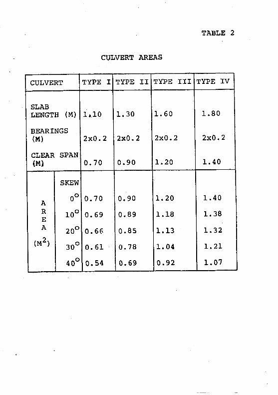
TABLE 2
CULVERT AREAS
CUI,VERT TYPE I TYPE II TYPE II I TYPE IV
SLABI,ENGTH (M)
BEARINGS( M )
CLEAR SPAN(M)
1r 10
2x0.2
0 . 70
1 . 30
2x0.2
0 .90
1 . 60
2xQ.2
1 . 20
1 .80
2xQ.2
l . 40
AREA
(u2)
SKEW
00
r00
200
300
400
0 .70
0 . 69
0 . 66
0 . 61
0 . 54
0. 90
0 .89
0 .85
0 .78
0 .69
L .20
1 .19
1 .13
1 .04
0 .92
I .40
r .38
I .32
L .2L
r .07

TABLE 3
GENERAL LAYOUT
SLAB CULVERI, LOTIG]TUDINAL SECTTON
PtAN
EltD WALL, sECrloN 3-3

TABLE 1
OECK SLAB
P'
l - t
50
#-,-qGt - - s ,
IYPE I0.t0? mt260 k9

iflliilrfliriflrItir
{iir l .
{;iiliiiiili i
TABLE 5
DECK SLAB
sEcrfoi l 2-2
TYPE T0125 mr
JiD*s9oo

TAELE 6
sgeK $1,{ffi
KI
l*
l-
s
ffi
4l3€)
"
U-T.
\tl3_
ECTrO{
==#
\__\@3r
I
-r
@
3 - 3
eI:===:-:::=T;;
LJiJ-i-i{+
l!tul?(9 160 t
E l!4!-
l---*---i.l: . lt-Krli \,.",@
50 -_-- *r
i - * 3I
.;;;:;E"=<l$J-:4'gL
IL- i )1
t{t
iloLm .
sbofn
o x I
mDossrlPlion
wr.k g
F;1
# TYP€ IItr0.150 rnsSo fig
50 12 t.t5 5 0.25llS
0 .?
a7 l 2 t.t0 2 7.60 3.8
5t l2 0.{5 5 2.25t--tL*-
2t
Yotct t
t

TABLE 7
DECK SLAB
P'
Lt,
s€cf lol t t -{
tlcafn
, . t z in , l
IYPE If,0.16? mtO0 Kg

TABLE 8
MEASUREMENT FORM
DtvrsroNOISTRrcT
ROAO NO. A.-MME
ROAO FROX
KII. PAYEM
FORIIAIION WIDTH tl. A
cuLvERT tElcrlt . M.
IIIYER' TEVEL : INLET
IIYPE 0r Yroix
IO
EXT TYPE
NGLE OF SI(E
OU?LEI
AiEA OF CATCHHE}IT N€CTARE
IIAIURE OF CATCHHEXT
HOIJI{TA|iOU3 / HtLtY' RO[LtilO' F t AT
WA?ERWAY OPEXIild AiEA 12
RECOIIIIEXOED O€SlGll: TYPE NO. OF Uilll3
xuHlEi of oEcr 3LAl3 REOUIiEO
EOUIPTE}I'
COI{CRETE HIXER
IRACTOR, IACX HOE
F[AIEEO, CRA]C
YIIRATIf,O PIATE
YIIRAIIilO FOTER
coa?RE530R
WAISR TAI|XER
NO. IAAOUR
FOREIIAX
OFERATOR/ORIVER
MASOX
LABOURER, CONCREIE
LABq'RER. GE}IERAI
wAlcHt|At{
]to.
llAT.EETAtjTAOGREGA'E II,'- X
sAr{D rdCEHEXT UO
BRTCKnaASOT{RY gt
FoitawoRt( pr
IOOXLEILIEYETwARNtilo Stcfas
lAeRreRi
RED tAt{'S
WHEET BARROUS
oArE. SqrAruRE A?PiOVED

TABLE 9
RSPORT FORM
I
iIlI
0lvtsroNorstRrclROAD NO. &ROAD FiOH
K M . F I O H
?lUMf:ign OF SAUAR€ METRES
. T O. . T O
DAY**---l REHARKS
gourFHEHr
ROLLgRS
ASPH. DtstRt6uttsqg
AWFI. HEAIERS
WHEET IOADERS
EHIP IPREAOEfiIS
AI?H. I(E'TLSE
G{U{OFRts
coHPr?gs90n$TRUCHS
Plcx - uPt
TYFE. OF WORK
MAIERIA!3
A6CREOATEB
AsPHAII
OTHERs
tAtouiFOEE}{lXe{itRATo*lsr'sntv{il$
tABOUf,ERS
WEAIHER gUN / CLOUOY / RAI' | ' HOT / COTO

TABLE 10
MONTHLY REPORT
MONTHLY REPORI
DtsIRtcT sEcTloll
. T O .
lrour t
f u TI.
ilot{tHtY
og.EEgts.:
PAVEIlENT
SHOULOERS
SIDE DRAINS
CIT.VE RIS
I enrooesIII FLOOD PONT3
sroPEs
CATCruIETT
DIYERSION
RIYERS
OUAR'ERI-Y
KTI. I RETARXS
INATE. sFNAruR€ OAIE t Ifi
t