JIS Grid - Lovejoy, Inc. · 2018-01-31 · Coupling Selection Worksheet, Page GD-9 Grid Standard...
19
213 www.lovejoy-inc.com GD- JW Table of Contents 213 www.lovejoy-inc.com Table of Contents GD GD-1 In This Section: ■ Horizontal Cover Style ■ Vertical Cover Style ■ Full Spacer Style ■ Half Spacer Style Grid
Transcript of JIS Grid - Lovejoy, Inc. · 2018-01-31 · Coupling Selection Worksheet, Page GD-9 Grid Standard...
213www.lovejoy-inc.com GD-
JWJI
SC
JSF
MC
GH
PG
DD
TSP
UJ
VSD
RSL
DED
JWJIS
CJ
SFM
CG
HP
GD
DT
SPU
JVSD
RSLD
EDTable of Contents
213www.lovejoy-inc.com
Table of Contents
JWJI
SC
JSF
MC
GH
PG
DD
TSP
UJ
VSD
RSL
DED
JWJIS
CJ
SFM
CG
HP
GD
DT
SPU
JVSD
RSLD
ED
GD-1
In This Section: ■ Horizontal Cover Style
■ Vertical Cover Style
■ Full Spacer Style
■ Half Spacer Style
Grid
JWJI
SC
JSF
MC
GH
PG
DD
TSP
UJ
VSD
RSL
DED
JWJIS
CJ
SFM
CG
HP
GD
DT
SPU
JVSD
RSLD
ED
Table of Contents
214 630-852-0500
When using Lovejoy products, you must follow these instructions and take the following precautions. Failure to do so may cause the power transmission product to break and parts to be thrown with sufficient force to cause severe injury or death.
Refer to this Lovejoy Catalog for proper selection, sizing, horsepower, torque range, and speed range of power transmission products, including elastomeric elements for couplings. Follow the installation instructions included with the product, and in the individual product catalogs for proper installation of power transmission products. Do not exceed catalog ratings.
During start up and operation of power transmission product, avoid sudden shock loads. Coupling assembly should operate quietly and smoothly. If coupling assembly vibrates or makes beating sound, shut down immediately, and recheck alignment. Shortly after initial operation and periodically thereafter, where applicable, inspect coupling assembly for: alignment, wear of elastomeric element, bolt torques, and flexing elements for signs of fatigue. Do not operate coupling assembly if alignment is improper, or where applicable, if elastomeric element is damaged, or worn to less than 75% of its original thickness.
Do not use any of these power transmission products for elevators, man lifts, or other devices that carry people. If the power transmission product fails, the lift device could fall resulting in severe injury or death.
For all power transmission products, you must install suitable guards in accordance with OSHA and American Society of Mechanical Engineers Standards. Do not start power transmission product before suitable guards are in place. Failure to properly guard these products may result in severe injury or death from personnel contacting moving parts or from parts being thrown from assembly in the event the power transmission product fails.
If you have any questions, contact the Lovejoy Engineering Department at 1-630-852-0500.
Safety Warning
Table of Contents
GD-2
Grid
JWJI
SC
JSF
MC
GH
PG
DD
TSP
UJ
VSD
RSL
DED
JWJIS
CJ
SFM
CG
HP
GD
DT
SPU
JVSD
RSLD
ED
215www.lovejoy-inc.com
Table of Contents
Table of Contents
GD-3
Grid
Overview ......................................................................................................................................216 .................... GD-4
Selection Process ........................................................................................................................217 .................... GD-5
Application Service Factors > Selection Data .............................................................................219 .................... GD-7
Grid Coupling Selection Worksheet .............................................................................................221 .................... GD-9
Standard Coupling > Performance Data .....................................................................................222 .................. GD-10
Standard Coupling > Dimensional Data ......................................................................................223 .................. GD-11
Spacer Style > Performance / Dimensional Data ........................................................................224 .................. GD-12
Spacer Style > Spacer Hub Selection .........................................................................................225 .................. GD-13
Misalignment Capability > Item Selection ....................................................................................226 .................. GD-14
Industry Standard Interchange Chart > Item Selection ...............................................................227 .................. GD-15
Grid Coupling Hubs – Inch Bore / Keyway > Item Selection .......................................................228 .................. GD-16
Grid Coupling Hubs – Metric Bore / Keyway > Item Selection ....................................................229 .................. GD-17
Grid Coupling – Taper Lock Hubs > Item Selection .....................................................................230 .................. GD-18
Grid Coupling – Component Part Numbers > Item Selection ......................................................231 .................. GD-19
Running Section Page No. Page No.
JWJI
SC
JSF
MC
GH
PG
DD
TSP
UJ
VSD
RSL
DED
JWJIS
CJ
SFM
CG
HP
GD
DT
SPU
JVSD
RSLD
ED
216 630-852-0500
Table of Contents
GD-4
Grid
Overview
The Power of Torsional DampeningLovejoy is pleased to be able to provide quality grid couplings covering a large number of industry standard sizes and lengths. The Lovejoy grid style coupling has proven itself in performance and popularity over a wide range of applications.
Lovejoy’s grid style coupling design has demonstrated its ability to dampen vibration by as much as 30% and can cushion shock loads that could cause damage to both the driving and driven equipment. The tapered grid spring design absorbs impact energy by spreading the energy out over the full length of the grid spring thus reducing the magnitude of the torque spikes.
The Lovejoy design uses a curved hub tooth profile which creates a progressive contact with the flexible grid spring as the application torque increases. This feature provides a more effective and efficient transmission of power in properly aligned couplings.
Lovejoy’s versatile design of industry standard hubs and grid springs for both horizontal and vertical cover styles allow Lovejoy couplings to be interchangeable with other industry standard grid couplings and components.
Proper grid coupling installation and maintenance can add to a longer coupling life. Grid spring replacement is simple and can be performed at a fraction of the cost and time of a complete coupling.
Features ■ High tensile, shot-peened alloy steel grid springs and precision machined hubs ensure superior coupling performance and long life.
■ Lovejoy’s grid couplings with tapered grids are designed to be interchangeable with other industry standard grid couplings with both horizontal and vertical grid covers.
■ Lovejoy grid couplings are designed for ease of installation and maintenance reducing labor and downtime costs.
■ The torsional flexibility and resilience of Lovejoy grid couplings helps reduce vibration and cushions shock and impact loads.
■ Cover fasteners can be provided in either Inch or Metric sizes.
■ Excellent for use in applications where the equipment is close coupled or spaced apart requiring a spacer style coupling arrangement.
■ Stock spacer designs are available or requests for custom spacer lengths can be addressed by Lovejoy engineering.
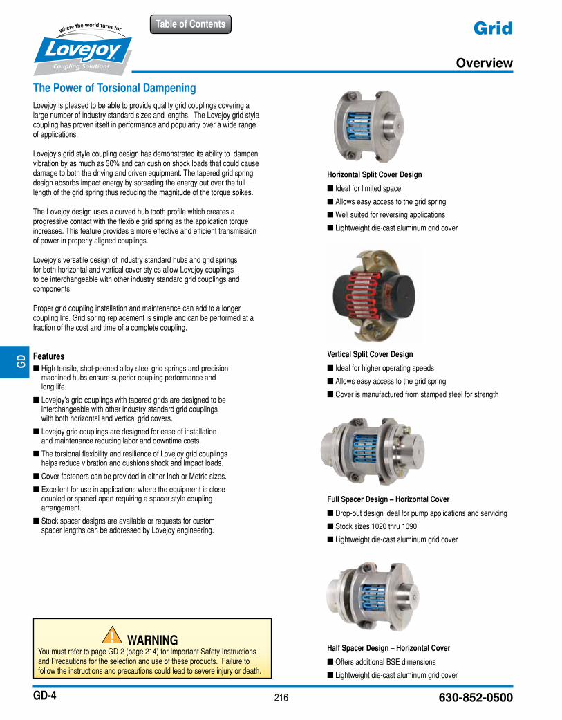
Horizontal Split Cover Design
■ Ideal for limited space
■ Allows easy access to the grid spring
■ Well suited for reversing applications
■ Lightweight die-cast aluminum grid cover
Vertical Split Cover Design
■ Ideal for higher operating speeds
■ Allows easy access to the grid spring
■ Cover is manufactured from stamped steel for strength
Full Spacer Design – Horizontal Cover
■ Drop-out design ideal for pump applications and servicing
■ Stock sizes 1020 thru 1090
■ Lightweight die-cast aluminum grid cover
Half Spacer Design – Horizontal Cover
■ Offers additional BSE dimensions
■ Lightweight die-cast aluminum grid cover
JWJI
SC
JSF
MC
GH
PG
DD
TSP
UJ
VSD
RSL
DED
JWJIS
CJ
SFM
CG
HP
GD
DT
SPU
JVSD
RSLD
ED
WARNINGYou must refer to page GD-2 (page 214) for Important Safety Instructions and Precautions for the selection and use of these products. Failure to follow the instructions and precautions could lead to severe injury or death.
217www.lovejoy-inc.com
Table of Contents
GD-5
Grid
Selection Process
The following information is necessary when making a Grid coupling selection:
■ Description of motor or engine, the horse power (or KW), and RPM at slowest coupling speed while under load
■ Description of the driven equipment
■ Shaft and keyway sizes and the type of fit for driver and driven equipment (clearance or interference)**
■ Shaft separation (BSE)
■ Physical space limitations (see Application Worksheet)
■ Determine what the environmental conditions will be, such as temperature, corrosive conditions, interference from surrounding structures, etc.
** By default, sizes 1020 – 1090 will be clearance fit, sizes 1100 – 1200 will be interference fit.
** Lovejoy machines all bores and keyways to meet the dimensional and tolerance specifications per ANSI/AGMA 9002-B04 for inch bores, or ISO 286-2 for metric bores.
Typical grid couplings consist of two grid hubs, a grid spring, and a cover assembly. When the shaft separation requires a spacer style coupling, the coupling will consist of two shaft hubs, two spacer hubs, a grid spring, and a horizontal cover assembly.
The following charts are available to assist in making the best possible grid coupling selection:
■ Coupling Selection Worksheet, Page GD-9
■ Grid Standard Interchange Chart, Page GD-15
■ Application Service Factors, Pages GD-7 and GD-8
■ General Service Factors, Page GD-6 (bottom)
■ Performance and Dimensional Page GD-10 thru GD-11 Data for Standard Grid Couplings
■ Performance and Dimensional Page GD-12 Data for Spacer Grid Couplings
■ Grid Coupling Part Numbers Page GD-16 thru GD19 for Standard Components
Formulas Used To Calculate Torque:Application Torque (in-lbs) = ( horse power x 63025 )
RPM
Application Torque (Nm) = ( horse power x 9550 ) RPM
Selection Torque = Application Torque x Service Factor
High Peak Loads and Brake ApplicationsFor applications where high peak loads or high braking torques might be present, the following additional information will be necessary:
■ System peak torque and frequency
■ Duty cycle
■ Brake torque rating
The selection torque formula is similar to the formula shown above except that the application torque should be doubled prior to applying the service factor.
Application Torque (in-lbs) = ( horse power x 63025 ) RPM
Application Torque (Nm) = ( horse power x 9550 ) RPM
Selection Torque = 2 x Application Torque x Service Factor
Please feel free to contact Lovejoy Application Engineering or Technical Support for assistance with additional grid coupling questions.
Step 1: Determine the application torque using the formula shown above.
Step 2: Select the Service Factor from the charts on pages GD-7 and GD-8. For applications not displayed use the chart shown to the right. Determine the Selection Torque using the formula shown above.
Step 3: Using the selection torque as calculated, refer to the Performance Chart on page GD-10 to determine the minimum size grid coupling that will accommodate the torque.
Step 4: Compare the maximum bore for the size selected and ensure the required bore sizes do not exceed the maximum allowable. If the required bore size is larger, step up to the next size coupling and check to see if the bore sizes will fit.
Step 5: Using the selected coupling size, compare the bore and keyway sizes with the charts located on pages GD-16 thru GD-17 for UPC part numbers.
Step 6: Contact your local industrial supplier with the part numbers to place your order.
See the Selection Example process on the next page.
Grid Coupling Selection Process
JWJI
SC
JSF
MC
GH
PG
DD
TSP
UJ
VSD
RSL
DED
JWJIS
CJ
SFM
CG
HP
GD
DT
SPU
JVSD
RSLD
ED
Steps In Selecting A Grid Coupling
218 630-852-0500
Table of Contents
GD-6
Grid
Selection Process
Application DescriptionA company would like to use a grid coupling to connect a standard AC electric motor to a rotary lobe compressor. The electric motor is rated for 60 horsepower running at 1,760 RPM. The shaft size on the electric motor (driver) is 2-1/8 inches with a standard 1/2” square key. The shaft size on the compressor (driven) is 48 millimeters with a standard 14mm key. Both the motor and compressor shaft are 3 inches long and the gap (BSE) between the shaft ends is 1/8 inch.
The following steps provide an excellent selection process that will work for most standard grid coupling selections. For assistance in this selection process, feel free to contact Lovejoy Application Engineering or Technical Support.
Step 1: Using the information provided by the customer, determine the application torque:
Application Torque (in-lbs) = ( horse power x 63025 ) RPM
for this example:
Application Torque (in-lbs) = ( 60 x 63025 ) = 2,149 in-lbs1,760
Step 2: Select the application service factor from the chart on pages GD-7 and GD-8 to determine which value best corresponds to an electric motor driven rotary lobe style compressor. In the charts find the application category ‘Compressors’, ‘Rotary lobe and vane’, and under the column for ‘Electric Motors’, is the service factor number 1.25.
If the service factor did not appear on the service factor charts for the defined application, a generic value could be selected from the chart located on the right side of this page.
Step 3: Calculate the Selection Torque for the application:
Selection Torque = Application Torque x Service Factor
Selection Torque = 2,149 in-lbs x 1.25 = 2,687 in-lbs
Step 4: Reference the Grid Coupling Performance and Dimensional data on pages GD-10 and GD-11. Use the Selection Torque to make an initial selection based on the nominal torque allowed for the coupling size. The first coupling size that can accommodate 2,687 in-lbs or torque is the size 1050 grid coupling with a nominal torque rating of 3,850 in-lbs.
Step 5: Note, that the electric motor’s 2-1/8 inch shaft diameter exceeds the maximum allowable bore size for a size 1050 coupling which is 1-7/8 inches. Using the same chart, scan the column for maximum bore sizes and find the first coupling size larger than the 1050 that will accommodate the 2-1/8 inch bore size. The size 1060 coupling will accommodate the 2-1/8 inch bore. The horizontal cover can be selected since the application speed of 1,760 RPM does not exceed the coupling’s maximum speed of 4,350 RPM.
Step 6: Prior to finalizing the 1060 selection, it is always a good idea to review all of the coupling details to ensure the correct coupling has been selected. The following are the comparisons usually made.
1060 Coupling Application Acceptable?Torque: 6,050 in-lbs 2,687 in-lbs yesBore Size: 2-1/8” max 2-1/8” yesBSE 0.13” 1/8” yesSpeed 4,350 RPM 1,760 RPM yesMount length 5.13” OAL 6-1/8” yes
Check the Grid Series Misalignment Chart to ensure the application meets the misalignment requirements. If the items above are acceptable and the application misalignment falls within the allowable range of the 1060 grid coupling, the 1060 grid coupling appears to be the correct coupling for this application.
Step 7: Using the UPC Selection tables on Pages GD-16 thru GD-19, find the required hubs for the corresponding coupling size and the required Cover and Grid Assembly.
1060 Hub Bore 2-1/8” see page GD-16, use 05491
1060 Hub Bore 48mm see page GD-17, use 05815
1060 Horizontal Cover and Grid assembly with inch hardware see page GD-18, use 05353
Prefix all grid coupling part numbers with 697904
Selection Example
JWJI
SC
JSF
MC
GH
PG
DD
TSP
UJ
VSD
RSL
DED
JWJIS
CJ
SFM
CG
HP
GD
DT
SPU
JVSD
RSLD
ED
Typical Applications for Electric Motor or Turbine Driven Equipment
Typical Service Factor
Constant Torque such as Centrifugal Pumps, Blowers, and Compressors. 1.0
Continuous Duty with some torque variations including Printing Presses, Extruders, Forced Draft Fans. 1.5
Light shock loads from Briquetting Machine, Rubber Calendar, or Crane and Hoist. 2.0
Moderate shock loading as expected from a Car Dumper, Reciprocating Feeder, or Vibrating Screen. 2.5
Heavy Shock load with some negative torques from Crushers, Manipulators, and Braking Drum. 3.0
For applications like Reciprocating Compressors with frequent torque reversals which do not necessarily cause reverse rotations, contact Lovejoy Technical Support.
General Service Factors
219www.lovejoy-inc.com
Table of Contents
GD-7
GridApplication Service Factors
Selection Data
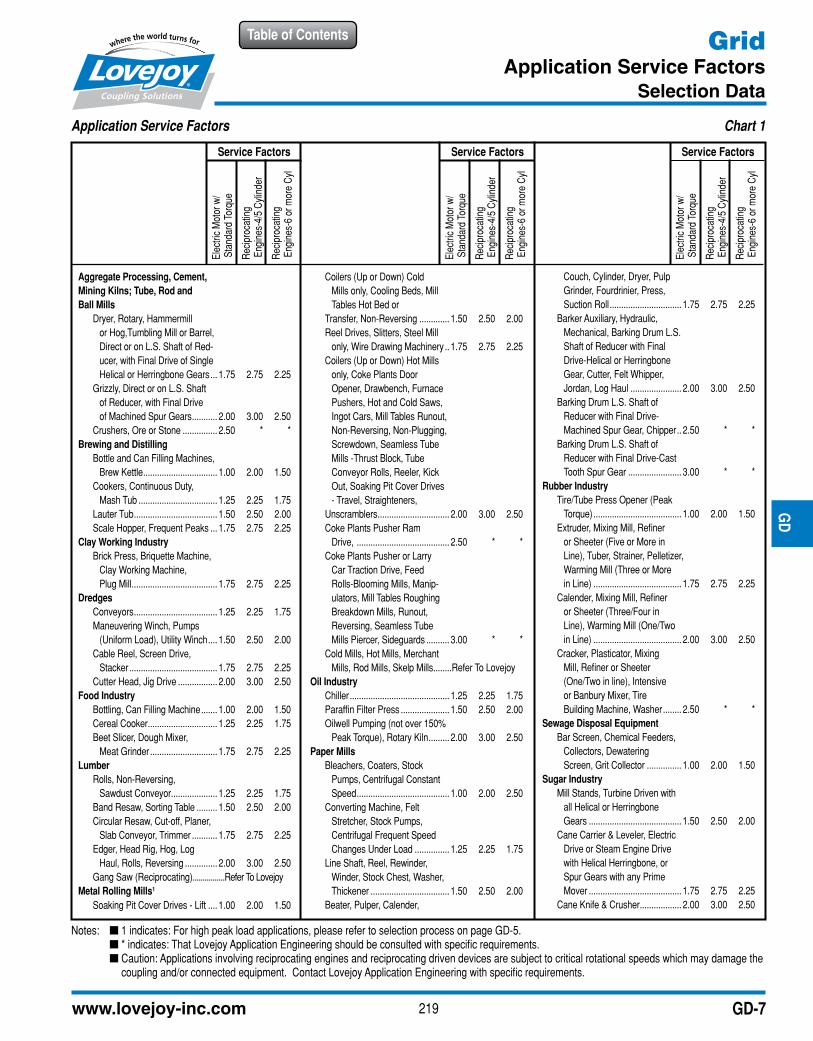
Application Service Factors Chart 1
Aggregate Processing, Cement,Mining Kilns; Tube, Rod and Ball Mills Dryer, Rotary, Hammermill or Hog,Tumbling Mill or Barrel, Direct or on L.S. Shaft of Red- ucer, with Final Drive of Single Helical or Herringbone Gears ... 1.75 2.75 2.25 Grizzly, Direct or on L.S. Shaft of Reducer, with Final Drive of Machined Spur Gears ........... 2.00 3.00 2.50 Crushers, Ore or Stone ............... 2.50 * *Brewing and Distilling Bottle and Can Filling Machines, Brew Kettle ................................ 1.00 2.00 1.50 Cookers, Continuous Duty, Mash Tub .................................. 1.25 2.25 1.75 Lauter Tub .................................... 1.50 2.50 2.00 Scale Hopper, Frequent Peaks ... 1.75 2.75 2.25Clay Working Industry Brick Press, Briquette Machine, Clay Working Machine, Plug Mill ..................................... 1.75 2.75 2.25Dredges Conveyors .................................... 1.25 2.25 1.75 Maneuvering Winch, Pumps (Uniform Load), Utility Winch .... 1.50 2.50 2.00 Cable Reel, Screen Drive, Stacker ...................................... 1.75 2.75 2.25 Cutter Head, Jig Drive ................. 2.00 3.00 2.50Food Industry Bottling, Can Filling Machine ....... 1.00 2.00 1.50 Cereal Cooker .............................. 1.25 2.25 1.75 Beet Slicer, Dough Mixer, Meat Grinder ............................. 1.75 2.75 2.25Lumber Rolls, Non-Reversing, Sawdust Conveyor.................... 1.25 2.25 1.75 Band Resaw, Sorting Table ......... 1.50 2.50 2.00 Circular Resaw, Cut-off, Planer, Slab Conveyor, Trimmer ........... 1.75 2.75 2.25 Edger, Head Rig, Hog, Log Haul, Rolls, Reversing .............. 2.00 3.00 2.50 Gang Saw (Reciprocating) ................Refer To LovejoyMetal Rolling Mills1
Soaking Pit Cover Drives - Lift .... 1.00 2.00 1.50
Coilers (Up or Down) Cold Mills only, Cooling Beds, Mill Tables Hot Bed or Transfer, Non-Reversing ............. 1.50 2.50 2.00 Reel Drives, Slitters, Steel Mill only, Wire Drawing Machinery .. 1.75 2.75 2.25 Coilers (Up or Down) Hot Mills only, Coke Plants Door Opener, Drawbench, Furnace Pushers, Hot and Cold Saws, Ingot Cars, Mill Tables Runout, Non-Reversing, Non-Plugging, Screwdown, Seamless Tube Mills -Thrust Block, Tube Conveyor Rolls, Reeler, Kick Out, Soaking Pit Cover Drives - Travel, Straighteners, Unscramblers ............................... 2.00 3.00 2.50 Coke Plants Pusher Ram Drive, ........................................ 2.50 * * Coke Plants Pusher or Larry Car Traction Drive, Feed Rolls-Blooming Mills, Manip- ulators, Mill Tables Roughing Breakdown Mills, Runout, Reversing, Seamless Tube Mills Piercer, Sideguards .......... 3.00 * * Cold Mills, Hot Mills, Merchant Mills, Rod Mills, Skelp Mills ........Refer To LovejoyOil Industry Chiller ........................................... 1.25 2.25 1.75 Paraffin Filter Press ..................... 1.50 2.50 2.00 Oilwell Pumping (not over 150% Peak Torque), Rotary Kiln ......... 2.00 3.00 2.50Paper Mills Bleachers, Coaters, Stock Pumps, Centrifugal Constant Speed ........................................ 1.00 2.00 2.50 Converting Machine, Felt Stretcher, Stock Pumps, Centrifugal Frequent Speed Changes Under Load ............... 1.25 2.25 1.75 Line Shaft, Reel, Rewinder, Winder, Stock Chest, Washer, Thickener .................................. 1.50 2.50 2.00 Beater, Pulper, Calender,
Couch, Cylinder, Dryer, Pulp Grinder, Fourdrinier, Press, Suction Roll ............................... 1.75 2.75 2.25 Barker Auxiliary, Hydraulic, Mechanical, Barking Drum L.S. Shaft of Reducer with Final Drive-Helical or Herringbone Gear, Cutter, Felt Whipper, Jordan, Log Haul ...................... 2.00 3.00 2.50 Barking Drum L.S. Shaft of Reducer with Final Drive- Machined Spur Gear, Chipper .. 2.50 * * Barking Drum L.S. Shaft of Reducer with Final Drive-Cast Tooth Spur Gear ....................... 3.00 * *Rubber Industry Tire/Tube Press Opener (Peak Torque) ...................................... 1.00 2.00 1.50 Extruder, Mixing Mill, Refiner or Sheeter (Five or More in Line), Tuber, Strainer, Pelletizer, Warming Mill (Three or More in Line) ...................................... 1.75 2.75 2.25 Calender, Mixing Mill, Refiner or Sheeter (Three/Four in Line), Warming Mill (One/Two in Line) ...................................... 2.00 3.00 2.50 Cracker, Plasticator, Mixing Mill, Refiner or Sheeter (One/Two in line), Intensive or Banbury Mixer, Tire Building Machine, Washer ........ 2.50 * *Sewage Disposal Equipment Bar Screen, Chemical Feeders, Collectors, Dewatering Screen, Grit Collector ............... 1.00 2.00 1.50Sugar Industry Mill Stands, Turbine Driven with all Helical or Herringbone Gears ........................................ 1.50 2.50 2.00 Cane Carrier & Leveler, Electric Drive or Steam Engine Drive with Helical Herringbone, or Spur Gears with any Prime Mover ........................................ 1.75 2.75 2.25 Cane Knife & Crusher .................. 2.00 3.00 2.50
Elec
tric
Mot
or w
/ S
tand
ard
Torq
ue
Rec
ipro
catin
g E
ngin
es-4
/5 C
ylin
der
Rec
ipro
catin
g E
ngin
es-6
or m
ore
Cyl
Service Factors
Elec
tric
Mot
or w
/ S
tand
ard
Torq
ue
Rec
ipro
catin
g E
ngin
es-4
/5 C
ylin
der
Rec
ipro
catin
g E
ngin
es-6
or m
ore
Cyl
Service Factors
Elec
tric
Mot
or w
/ S
tand
ard
Torq
ue
Rec
ipro
catin
g E
ngin
es-4
/5 C
ylin
der
Rec
ipro
catin
g E
ngin
es-6
or m
ore
Cyl
Service Factors
Notes: n 1 indicates: For high peak load applications, please refer to selection process on page GD-5. n * indicates: That Lovejoy Application Engineering should be consulted with specific requirements. n Caution: Applications involving reciprocating engines and reciprocating driven devices are subject to critical rotational speeds which may damage the
coupling and/or connected equipment. Contact Lovejoy Application Engineering with specific requirements.
JWJI
SC
JSF
MC
GH
PG
DD
TSP
UJ
VSD
RSL
DED
JWJIS
CJ
SFM
CG
HP
GD
DT
SPU
JVSD
RSLD
ED
220 630-852-0500
Table of Contents
GD-8
GridApplication Service Factors
Selection Data
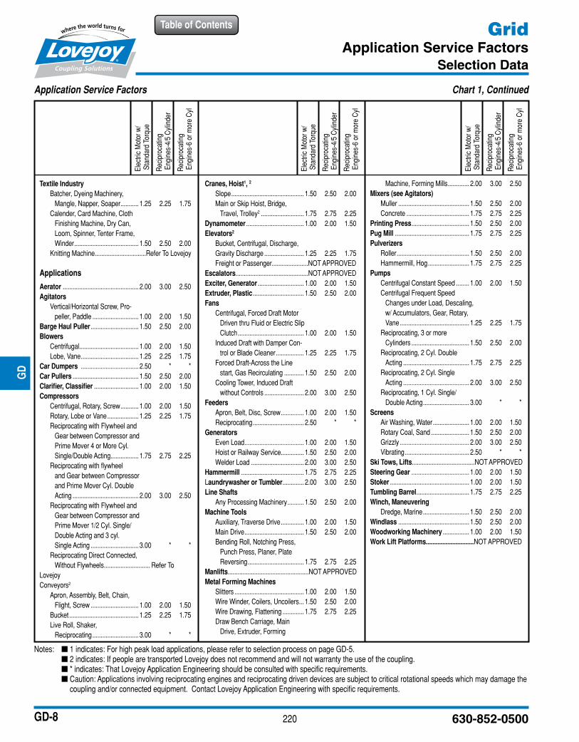
Application Service Factors Chart 1, Continued
Textile Industry Batcher, Dyeing Machinery, Mangle, Napper, Soaper ........... 1.25 2.25 1.75 Calender, Card Machine, Cloth Finishing Machine, Dry Can, Loom, Spinner, Tenter Frame, Winder ....................................... 1.50 2.50 2.00 Knitting Machine............................... Refer To Lovejoy
Applications
Aerator .............................................. 2.00 3.00 2.50Agitators Vertical/Horizontal Screw, Pro- peller, Paddle ............................ 1.00 2.00 1.50Barge Haul Puller ............................. 1.50 2.50 2.00Blowers Centrifugal .................................... 1.00 2.00 1.50 Lobe, Vane ................................... 1.25 2.25 1.75Car Dumpers ................................... 2.50 * *Car Pullers ........................................ 1.50 2.50 2.00Clarifier, Classifier ........................... 1.00 2.00 1.50Compressors Centrifugal, Rotary, Screw ........... 1.00 2.00 1.50 Rotary, Lobe or Vane ................... 1.25 2.25 1.75 Reciprocating with Flywheel and Gear between Compressor and Prime Mover 4 or More Cyl. Single/Double Acting ................. 1.75 2.75 2.25 Reciprocating with flywheel and Gear between Compressor and Prime Mover Cyl. Double Acting ........................................ 2.00 3.00 2.50 Reciprocating with Flywheel and Gear between Compressor and Prime Mover 1/2 Cyl. Single/ Double Acting and 3 cyl. Single Acting ............................. 3.00 * * Reciprocating Direct Connected, Without Flywheels ............................ Refer To Lovejoy Conveyors2
Apron, Assembly, Belt, Chain, Flight, Screw ............................. 1.00 2.00 1.50 Bucket .......................................... 1.25 2.25 1.75 Live Roll, Shaker, Reciprocating ............................ 3.00 * *
Cranes, Hoist1, 2
Slope ............................................ 1.50 2.50 2.00 Main or Skip Hoist, Bridge, Travel, Trolley2 .......................... 1.75 2.75 2.25Dynamometer ................................... 1.00 2.00 1.50Elevators2
Bucket, Centrifugal, Discharge, Gravity Discharge ........................ 1.25 2.25 1.75 Freight or Passenger ......................NOT APPROVEDEscalators............................................NOT APPROVEDExciter, Generator ............................ 1.00 2.00 1.50Extruder, Plastic ............................... 1.50 2.50 2.00Fans Centrifugal, Forced Draft Motor Driven thru Fluid or Electric Slip Clutch ........................................ 1.00 2.00 1.50 Induced Draft with Damper Con- trol or Blade Cleaner ................. 1.25 2.25 1.75 Forced Draft-Across the Line start, Gas Recirculating ............ 1.50 2.50 2.00 Cooling Tower, Induced Draft without Controls ........................ 2.00 3.00 2.50Feeders Apron, Belt, Disc, Screw .............. 1.00 2.00 1.50 Reciprocating ............................... 2.50 * *Generators Even Load .................................... 1.00 2.00 1.50 Hoist or Railway Service .............. 1.50 2.50 2.00 Welder Load ................................ 2.00 3.00 2.50Hammermill ...................................... 1.75 2.75 2.25Laundrywasher or Tumbler ............. 2.00 3.00 2.50Line Shafts Any Processing Machinery .......... 1.50 2.50 2.00Machine Tools Auxiliary, Traverse Drive .............. 1.00 2.00 1.50 Main Drive .................................... 1.50 2.50 2.00 Bending Roll, Notching Press, Punch Press, Planer, Plate Reversing .................................. 1.75 2.75 2.25Manlifts.................................................NOT APPROVEDMetal Forming Machines Slitters .......................................... 1.00 2.00 1.50 Wire Winder, Coilers, Uncoilers ... 1.50 2.50 2.00 Wire Drawing, Flattening ............. 1.75 2.75 2.25 Draw Bench Carriage, Main Drive, Extruder, Forming
Machine, Forming Mills ............. 2.00 3.00 2.50Mixers (see Agitators) Muller ........................................... 1.50 2.50 2.00 Concrete ...................................... 1.75 2.75 2.25Printing Press ................................... 1.50 2.50 2.00Pug Mill ............................................. 1.75 2.75 2.25Pulverizers Roller ............................................ 1.50 2.50 2.00 Hammermill, Hog ......................... 1.75 2.75 2.25Pumps Centrifugal Constant Speed ........ 1.00 2.00 1.50 Centrifugal Frequent Speed Changes under Load, Descaling, w/ Accumulators, Gear, Rotary, Vane .......................................... 1.25 2.25 1.75 Reciprocating, 3 or more Cylinders ................................... 1.50 2.50 2.00 Reciprocating, 2 Cyl. Double Acting ........................................ 1.75 2.75 2.25 Reciprocating, 2 Cyl. Single Acting ........................................ 2.00 3.00 2.50 Reciprocating, 1 Cyl. Single/ Double Acting ............................ 3.00 * *Screens Air Washing, Water ...................... 1.00 2.00 1.50 Rotary Coal, Sand ....................... 1.50 2.50 2.00 Grizzly .......................................... 2.00 3.00 2.50 Vibrating ....................................... 2.50 * *Ski Tows, Lifts......................................NOT APPROVEDSteering Gear ................................... 1.00 2.00 1.50Stoker ................................................ 1.00 2.00 1.50Tumbling Barrel ................................ 1.75 2.75 2.25Winch, Maneuvering Dredge, Marine ............................ 1.50 2.50 2.00 Windlass ........................................... 1.50 2.50 2.00Woodworking Machinery ................ 1.00 2.00 1.50Work Lift Platforms.............................NOT APPROVED
Elec
tric
Mot
or w
/ S
tand
ard
Torq
ue
Rec
ipro
catin
g E
ngin
es-4
/5 C
ylin
der
Rec
ipro
catin
g E
ngin
es-6
or m
ore
Cyl
Elec
tric
Mot
or w
/ S
tand
ard
Torq
ue
Rec
ipro
catin
g E
ngin
es-4
/5 C
ylin
der
Rec
ipro
catin
g E
ngin
es-6
or m
ore
Cyl
Elec
tric
Mot
or w
/ S
tand
ard
Torq
ue
Rec
ipro
catin
g E
ngin
es-4
/5 C
ylin
der
Rec
ipro
catin
g E
ngin
es-6
or m
ore
Cyl
Notes: n 1 indicates: For high peak load applications, please refer to selection process on page GD-5. n 2 indicates: If people are transported Lovejoy does not recommend and will not warranty the use of the coupling. n * indicates: That Lovejoy Application Engineering should be consulted with specific requirements. n Caution: Applications involving reciprocating engines and reciprocating driven devices are subject to critical rotational speeds which may damage the
coupling and/or connected equipment. Contact Lovejoy Application Engineering with specific requirements.
JWJI
SC
JSF
MC
GH
PG
DD
TSP
UJ
VSD
RSL
DED
JWJIS
CJ
SFM
CG
HP
GD
DT
SPU
JVSD
RSLD
ED
221www.lovejoy-inc.com
Table of Contents
GD-9
Grid
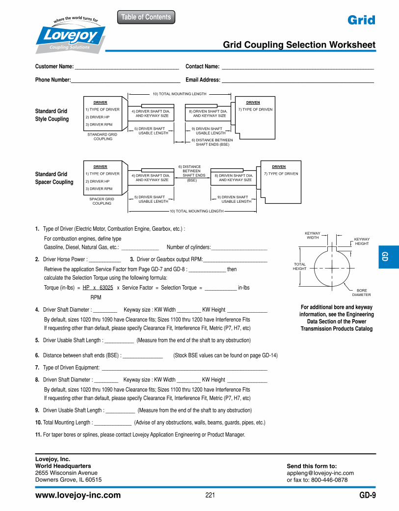
Grid Coupling Selection Worksheet
JWJI
SC
JSF
MC
GH
PG
DD
TSP
UJ
VSD
RSL
DED
JWJIS
CJ
SFM
CG
HP
GD
DT
SPU
JVSD
RSLD
ED
Customer Name: _______________________________________ Contact Name: _________________________________________________________
Phone Number:_________________________________________ Email Address: _________________________________________________________
Standard Grid Style Coupling
Standard Grid Spacer Coupling
1. Type of Driver (Electric Motor, Combustion Engine, Gearbox, etc.) :
For combustion engines, define typeGasoline, Diesel, Natural Gas, etc.: ______________ Number of cylinders: _____________________
2. Driver Horse Power : ____________ 3. Driver or Gearbox output RPM: ________________________
Retrieve the application Service Factor from Page GD-7 and GD-8 : ______________ thencalculate the Selection Torque using the following formula:
Torque (in-lbs) = HP x 63025 x Service Factor = Selection Torque = ____________ in-lbs
RPM
4. Driver Shaft Diameter : _________ Keyway size : KW Width _________ KW Height _______________
By default, sizes 1020 thru 1090 have Clearance fits; Sizes 1100 thru 1200 have Interference FitsIf requesting other than default, please specify Clearance Fit, Interference Fit, Metric (P7, H7, etc)
5. Driver Usable Shaft Length : ___________ (Measure from the end of the shaft to any obstruction)
6. Distance between shaft ends (BSE) : _______________ (Stock BSE values can be found on page GD-14)
7. Type of Driven Equipment: ______________________________________________________________
8. Driven Shaft Diameter : _________ Keyway size : KW Width _________ KW Height _______________
By default, sizes 1020 thru 1090 have Clearance fits; Sizes 1100 thru 1200 have Interference FitsIf requesting other than default, please specify Clearance Fit, Interference Fit, Metric (P7, H7, etc)
9. Driven Usable Shaft Length : ___________ (Measure from the end of the shaft to any obstruction)
10. Total Mounting Length : ______________ (Advise of any obstructions, walls, beams, guards, pipes, etc.)
11. For taper bores or splines, please contact Lovejoy Application Engineering or Product Manager.
For additional bore and keyway information, see the Engineering
Data Section of the Power Transmission Products Catalog
Lovejoy, Inc.World Headquarters2655 Wisconsin AvenueDowners Grove, IL 60515
Send this form to:[email protected] fax to: 800-446-0878
222 630-852-0500
Table of Contents
GD-10
Grid Standard Coupling
Performance Data
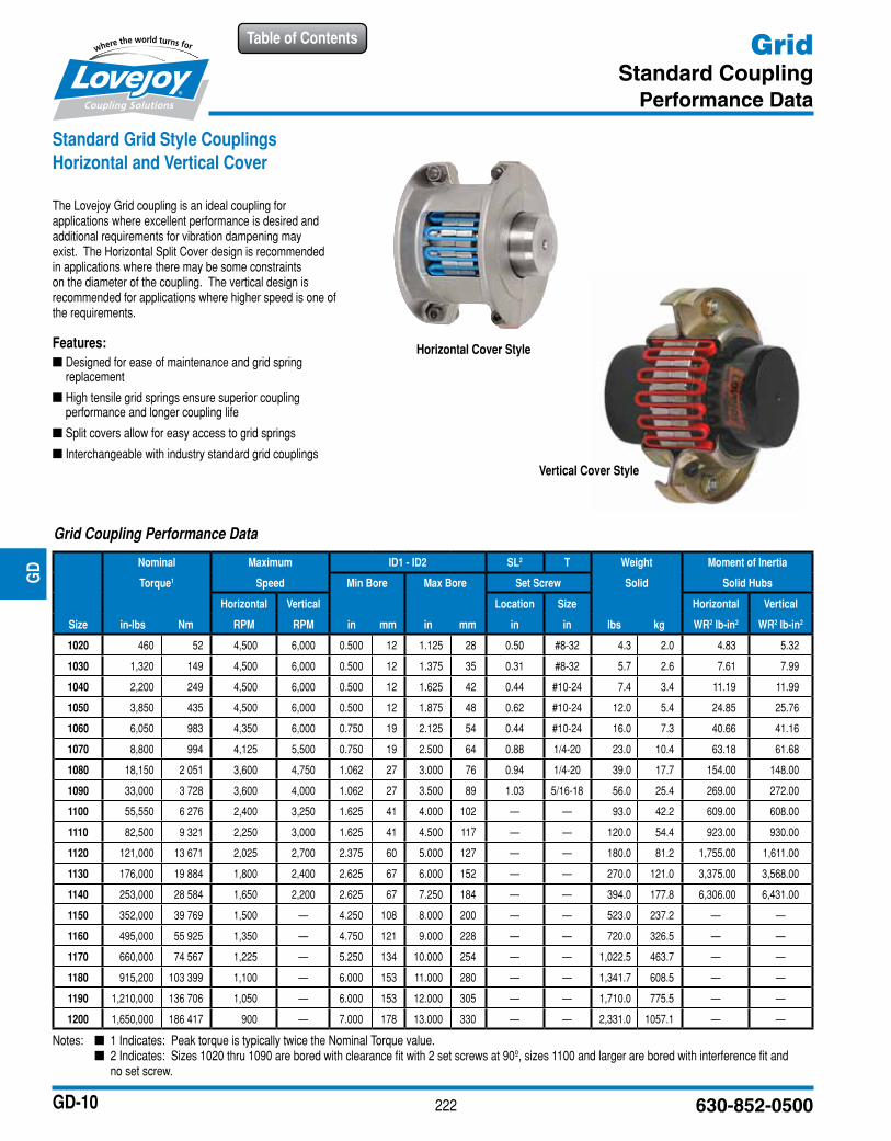
Notes: n 1 Indicates: Peak torque is typically twice the Nominal Torque value. n 2 Indicates: Sizes 1020 thru 1090 are bored with clearance fit with 2 set screws at 90º, sizes 1100 and larger are bored with interference fit and
no set screw.
Standard Grid Style Couplings Horizontal and Vertical Cover
The Lovejoy Grid coupling is an ideal coupling for applications where excellent performance is desired and additional requirements for vibration dampening may exist. The Horizontal Split Cover design is recommended in applications where there may be some constraints on the diameter of the coupling. The vertical design is recommended for applications where higher speed is one of the requirements.
Features: ■ Designed for ease of maintenance and grid spring replacement
■ High tensile grid springs ensure superior coupling performance and longer coupling life
■ Split covers allow for easy access to grid springs
■ Interchangeable with industry standard grid couplings
JWJI
SC
JSF
MC
GH
PG
DD
TSP
UJ
VSD
RSL
DED
JWJIS
CJ
SFM
CG
HP
GD
DT
SPU
JVSD
RSLD
ED
Horizontal Cover Style
Vertical Cover Style
Grid Coupling Performance Data
Nominal Maximum ID1 - ID2 SL2 T Weight Moment of Inertia
Torque1 Speed Min Bore Max Bore Set Screw Solid Solid Hubs
Horizontal Vertical Location Size Horizontal Vertical
Size in-lbs Nm RPM RPM in mm in mm in in lbs kg WR2 lb-in2 WR2 lb-in2
1020 460 52 4,500 6,000 0.500 12 1.125 28 0.50 #8-32 4.3 2.0 4.83 5.32
1030 1,320 149 4,500 6,000 0.500 12 1.375 35 0.31 #8-32 5.7 2.6 7.61 7.99
1040 2,200 249 4,500 6,000 0.500 12 1.625 42 0.44 #10-24 7.4 3.4 11.19 11.99
1050 3,850 435 4,500 6,000 0.500 12 1.875 48 0.62 #10-24 12.0 5.4 24.85 25.76
1060 6,050 983 4,350 6,000 0.750 19 2.125 54 0.44 #10-24 16.0 7.3 40.66 41.16
1070 8,800 994 4,125 5,500 0.750 19 2.500 64 0.88 1/4-20 23.0 10.4 63.18 61.68
1080 18,150 2 051 3,600 4,750 1.062 27 3.000 76 0.94 1/4-20 39.0 17.7 154.00 148.00
1090 33,000 3 728 3,600 4,000 1.062 27 3.500 89 1.03 5/16-18 56.0 25.4 269.00 272.00
1100 55,550 6 276 2,400 3,250 1.625 41 4.000 102 — — 93.0 42.2 609.00 608.00
1110 82,500 9 321 2,250 3,000 1.625 41 4.500 117 — — 120.0 54.4 923.00 930.00
1120 121,000 13 671 2,025 2,700 2.375 60 5.000 127 — — 180.0 81.2 1,755.00 1,611.00
1130 176,000 19 884 1,800 2,400 2.625 67 6.000 152 — — 270.0 121.0 3,375.00 3,568.00
1140 253,000 28 584 1,650 2,200 2.625 67 7.250 184 — — 394.0 177.8 6,306.00 6,431.00
1150 352,000 39 769 1,500 — 4.250 108 8.000 200 — — 523.0 237.2 — —
1160 495,000 55 925 1,350 — 4.750 121 9.000 228 — — 720.0 326.5 — —
1170 660,000 74 567 1,225 — 5.250 134 10.000 254 — — 1,022.5 463.7 — —
1180 915,200 103 399 1,100 — 6.000 153 11.000 280 — — 1,341.7 608.5 — —
1190 1,210,000 136 706 1,050 — 6.000 153 12.000 305 — — 1,710.0 775.5 — —
1200 1,650,000 186 417 900 — 7.000 178 13.000 330 — — 2,331.0 1057.1 — —
223www.lovejoy-inc.com
Table of Contents
GD-11
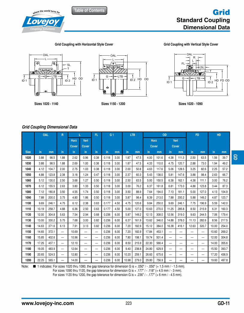
GridStandard Coupling
Dimensional Data
Note: n 1 indicates: For sizes 1020 thru 1080, the gap tolerance for dimension G is + .050" / - .050" (+ 1.5 mm / - 1.5 mm).For sizes 1090 thru 1120, the gap tolerance for dimension G is + .177" / - .118" (+ 4.5 mm / - 3 mm). For sizes 1120 thru 1200, the gap tolerance for dimension G is + .236" / - .177" (+ 6 mm / - 4.5 mm).
JWJI
SC
JSF
MC
GH
PG
DD
TSP
UJ
VSD
RSL
DED
JWJIS
CJ
SFM
CG
HP
GD
DT
SPU
JVSD
RSLD
ED
Grid Coupling with Horizontal Style Cover
Sizes 1020 - 1140 Sizes 1150 - 1200 Sizes 1020 - 1090
Grid Coupling with Vertical Style Cover
Grid Coupling Dimensional Data
OAL R L FL G 1 LTB OD FD HD
Horz Vert Horz Vert
Cover Cover Cover Cover
Size in mm in in in in in mm in mm in mm in mm in mm in mm
1020 3.88 98.5 1.88 2.62 0.96 0.38 0.118 3.00 1.87 47.5 4.00 101.6 4.38 111.3 2.50 63.5 1.56 39.7
1030 3.88 98.5 1.88 2.69 1.00 0.38 0.118 3.00 1.87 47.5 4.33 110.0 4.75 120.7 2.88 73.0 1.94 49.2
1040 4.12 104.7 2.00 2.75 1.03 0.38 0.118 3.00 2.00 50.8 4.63 117.6 5.06 128.5 3.25 82.6 2.25 57.2
1050 4.88 123.8 2.38 3.18 1.24 0.47 0.118 3.00 2.37 60.3 5.43 138.0 5.81 147.6 3.88 98.4 2.63 66.7
1060 5.12 130.0 2.50 3.68 1.27 0.50 0.118 3.00 2.50 63.5 5.93 150.5 6.38 162.1 4.38 111.1 3.00 76.2
1070 6.12 155.5 2.63 3.80 1.33 0.50 0.118 3.00 3.00 76.2 6.37 161.8 6.81 173.0 4.88 123.8 3.44 87.3
1080 7.12 180.8 3.50 4.55 1.74 0.50 0.118 3.00 3.50 88.9 7.64 194.0 7.13 181.1 5.00 127.0 4.13 104.9
1090 7.88 200.0 3.75 4.80 1.86 0.50 0.118 3.00 3.87 98.4 8.39 213.0 7.88 200.2 5.88 149.2 4.87 123.7
1100 9.69 246.1 4.75 6.12 2.38 0.63 0.177 4.50 4.75 120.6 9.84 250.0 9.69 246.1 7.75 196.9 5.59 142.0
1110 10.19 258.7 4.88 6.36 2.50 0.63 0.177 4.50 5.00 127.0 10.63 270.0 11.25 285.8 8.50 215.9 6.31 160.3
1120 12.00 304.8 5.63 7.54 2.94 0.68 0.236 6.00 5.87 149.2 12.13 308.0 12.56 319.0 9.63 244.5 7.06 179.4
1130 13.00 330.2 5.75 7.68 3.00 0.82 0.236 6.00 6.37 161.9 13.62 346.0 14.88 378.0 11.13 282.6 8.56 217.5
1140 14.63 371.6 6.13 7.91 3.13 0.82 0.236 6.00 7.20 182.9 15.12 384.0 16.38 416.1 12.63 320.7 10.00 254.0
1150 14.65 372.1 — 10.69 — — 0.236 6.00 7.20 182.9 17.84 453.1 — — — — 10.60 269.2
1160 15.85 402.6 — 10.96 — — 0.236 6.00 7.80 198.1 19.74 501.4 — — — — 12.00 304.8
1170 17.25 437.1 — 12.10 — — 0.236 6.00 8.50 215.9 22.30 566.4 — — — — 14.00 355.6
1180 19.05 483.9 — 12.64 — — 0.236 6.00 9.40 238.8 24.80 629.9 — — — — 15.50 393.7
1190 20.65 524.5 — 12.80 — — 0.236 6.00 10.20 259.1 26.60 675.6 — — — — 17.20 436.9
1200 22.25 565.1 — 14.00 — — 0.236 6.00 10.98 279.0 29.80 756.9 — — — — 19.60 497.8
224 630-852-0500
Table of Contents
GD-12
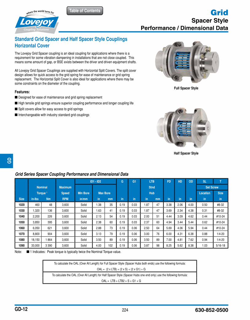
GridSpacer Style
Performance / Dimensional Data
Note: n 1 Indicates: Peak torque is typically twice the Nominal Torque value.
JWJI
SC
JSF
MC
GH
PG
DD
TSP
UJ
VSD
RSL
DED
JWJIS
CJ
SFM
CG
HP
GD
DT
SPU
JVSD
RSLD
ED
Standard Grid Spacer and Half Spacer Style Couplings Horizontal CoverThe Lovejoy Grid Spacer coupling is an ideal coupling for applications where there is a requirement for some vibration dampening in installations that are not close coupled. This means some amount of gap, or BSE exists between the driver and driven equipment shafts.
All Lovejoy Grid Spacer Couplings are supplied with Horizontal Split Covers. The split cover design allows for quick access to the grid spring for ease of maintenance or grid spring replacement. The Horizontal Split Cover is also ideal for applications where there may be some constraints on the diameter of the coupling.
Features: ■ Designed for ease of maintenance and grid spring replacement
■ High tensile grid springs ensure superior coupling performance and longer coupling life
■ Split covers allow for easy access to grid springs
■ Interchangeable with industry standard grid couplings
Full Spacer Style
Half Spacer Style
Grid Series Spacer Coupling Performance and Dimensional Data
ID1 - ID2 G G1 LTB FD HD OD SL T
Nominal Maximum Stnd Set Screw
Torque 1 Speed Min Bore Max Bore Hub Location Size
Size in-lbs Nm RPM in/mm in mm in in in mm in in in in in
1020 460 48 3,600 Solid 1.38 35 0.19 0.03 1.87 47 3.38 2.06 4.00 0.50 #8-32
1030 1,320 136 3,600 Solid 1.63 41 0.19 0.03 1.87 47 3.69 2.34 4.38 0.31 #8-32
1040 2,200 226 3,600 Solid 2.13 54 0.19 0.03 2.00 51 4.44 3.09 4.62 0.44 #10-24
1050 3,850 395 3,600 Solid 2.38 60 0.19 0.03 2.37 60 4.94 3.44 5.44 0.62 #10-24
1060 6,050 621 3,600 Solid 2.88 73 0.19 0.06 2.50 64 5.69 4.06 5.94 0.44 #10-24
1070 8,800 904 3,600 Solid 3.13 79 0.19 0.06 3.00 76 6.00 4.31 6.38 0.88 1/4-20
1080 18,150 1 864 3,600 Solid 3.50 89 0.19 0.06 3.50 89 7.00 4.81 7.62 0.94 1/4-20
1090 33,000 3 390 3,600 Solid 4.00 102 0.19 0.06 3.87 98 8.25 5.62 8.38 1.03 5/16-18
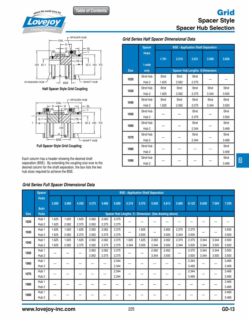
To calculate the OAL (Over All Length) for Full Spacer Style (Spacer Hubs both ends) use the following formula:
OAL = (2 x LTB) + (2 x S) + (2 x G1) + G
To calculate the OAL (Over All Length) for Half Spacer Style (Spacer Hubs one end only) use the following formula:
OAL = LTB + LTB2 + S + G1 + G
225www.lovejoy-inc.com
Table of Contents
GD-13
GridSpacer Style
Spacer Hub Selection
JWJI
SC
JSF
MC
GH
PG
DD
TSP
UJ
VSD
RSL
DED
JWJIS
CJ
SFM
CG
HP
GD
DT
SPU
JVSD
RSLD
ED
Full Spacer Style Grid Coupling
Each column has a header showing the desired shaft separation (BSE). By extending the coupling size over to the desired column for the shaft separation, the box lists the two hub sizes required to achieve the BSE.
Grid Series Full Spacer Dimensional Data
Spacer BSE - Application Shaft Separation
Hubs
3.500 3.980 4.250 4.375 4.688 5.000 5.219 5.375 5.656 5.813 5.969 6.125 6.938 7.094 7.250
Both
Size Hubs Spacer Hub Lengths S - Dimension (See drawing above)
1020Hub 1 1.625 1.625 1.625 2.062 2.062 2.375
— — — — — — — — —Hub 2 1.625 2.062 2.375 2.062 2.375 2.375
1030Hub 1 1.625 1.625 1.625 2.062 2.062 2.375
—1.625
—2.062 2.375 2.375
— —3.500
Hub 2 1.625 2.062 2.375 2.062 2.375 2.375 3.500 3.500 3.344 3.500 3.500
1040Hub 1 1.625 1.625 1.625 2.062 2.062 2.375 1.625 1.625 2.062 2.062 2.375 2.375 3.344 3.344 3.500
Hub 2 1.625 2.062 2.375 2.062 2.375 2.375 3.344 3.500 3.344 3.500 3.344 3.500 3.344 3.500 3.500
1050Hub 1
— — —2.062 2.062 2.375
— —2.062 2.062
—2.375 3.344 3.344 3.500
Hub 2 2.062 2.375 2.375 3.344 3.500 3.500 3.344 3.500 3.500
1060Hub 1
— — — — —2.344
— — — — —2.344
— —3.469
Hub 2 2.344 3.469 3.469
1070Hub 1
— — — — —2.344
— — — — —2.344
— —3.469
Hub 2 2.344 3.469 3.469
1080Hub 1
— — — — — — — — — — — — — —3.469
Hub 2 3.469
1090Hub 1
— — — — — — — — — — — — — —3.469
Hub 2 3.469
Grid Series Half Spacer Dimensional Data
Spacer BSE - Application Shaft Separation
Hubs
1.781 2.219 2.531 3.500 3.656
1-side
Size only Spacer Hub Lengths S-Dimension
1020Stnd Hub Stnd Stnd Stnd
— —Hub 2 1.625 2.062 2.375
1030Stnd Hub Stnd Stnd Stnd Stnd Stnd
Hub 2 1.625 2.062 2.375 3.344 3.500
1040Stnd Hub Stnd Stnd Stnd Stnd Stnd
Hub 2 1.625 2.062 2.375 3.344 3.500
1050Stnd Hub
— —Stnd
—Stnd
Hub 2 2.375 3.500
1060Stnd Hub
— —Stnd
—Stnd
Hub 2 2.344 3.469
1070Stnd Hub
— —Stnd
—Stnd
Hub 2 2.344 3.469
1080Stnd Hub
— — — —Stnd
Hub 2 3.469
1090Stnd Hub
— — — —Stnd
Hub 2 3.469
Half Spacer Style Grid Coupling
226 630-852-0500
Table of Contents
GD-14
GridMisalignment Capability
Item Selection
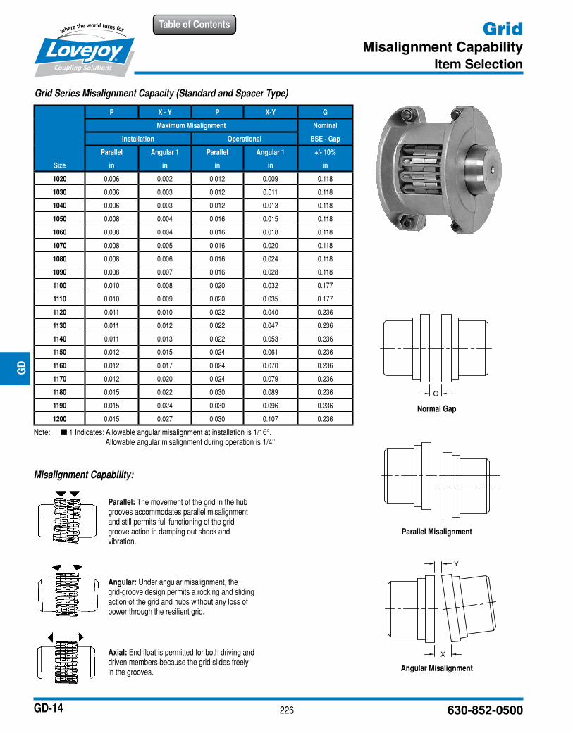
Misalignment Capability:
Parallel: The movement of the grid in the hub grooves accommodates parallel misalignment and still permits full functioning of the grid-groove action in damping out shock and vibration.
Angular: Under angular misalignment, the grid-groove design permits a rocking and sliding action of the grid and hubs without any loss of power through the resilient grid.
Axial: End float is permitted for both driving and driven members because the grid slides freely in the grooves.
Normal Gap
Angular Misalignment
Parallel Misalignment
JWJI
SC
JSF
MC
GH
PG
DD
TSP
UJ
VSD
RSL
DED
JWJIS
CJ
SFM
CG
HP
GD
DT
SPU
JVSD
RSLD
ED
Grid Series Misalignment Capacity (Standard and Spacer Type)
P X - Y P X-Y G
Maximum Misalignment Nominal
Installation Operational BSE - Gap
Parallel Angular 1 Parallel Angular 1 +/- 10%
Size in in in in in
1020 0.006 0.002 0.012 0.009 0.118
1030 0.006 0.003 0.012 0.011 0.118
1040 0.006 0.003 0.012 0.013 0.118
1050 0.008 0.004 0.016 0.015 0.118
1060 0.008 0.004 0.016 0.018 0.118
1070 0.008 0.005 0.016 0.020 0.118
1080 0.008 0.006 0.016 0.024 0.118
1090 0.008 0.007 0.016 0.028 0.118
1100 0.010 0.008 0.020 0.032 0.177
1110 0.010 0.009 0.020 0.035 0.177
1120 0.011 0.010 0.022 0.040 0.236
1130 0.011 0.012 0.022 0.047 0.236
1140 0.011 0.013 0.022 0.053 0.236
1150 0.012 0.015 0.024 0.061 0.236
1160 0.012 0.017 0.024 0.070 0.236
1170 0.012 0.020 0.024 0.079 0.236
1180 0.015 0.022 0.030 0.089 0.236
1190 0.015 0.024 0.030 0.096 0.236
1200 0.015 0.027 0.030 0.107 0.236
Note: n 1 Indicates: Allowable angular misalignment at installation is 1/16°.Allowable angular misalignment during operation is 1/4°.
227www.lovejoy-inc.com
Table of Contents
GD-15
GridIndustry Standard Interchange Chart
Item Selection
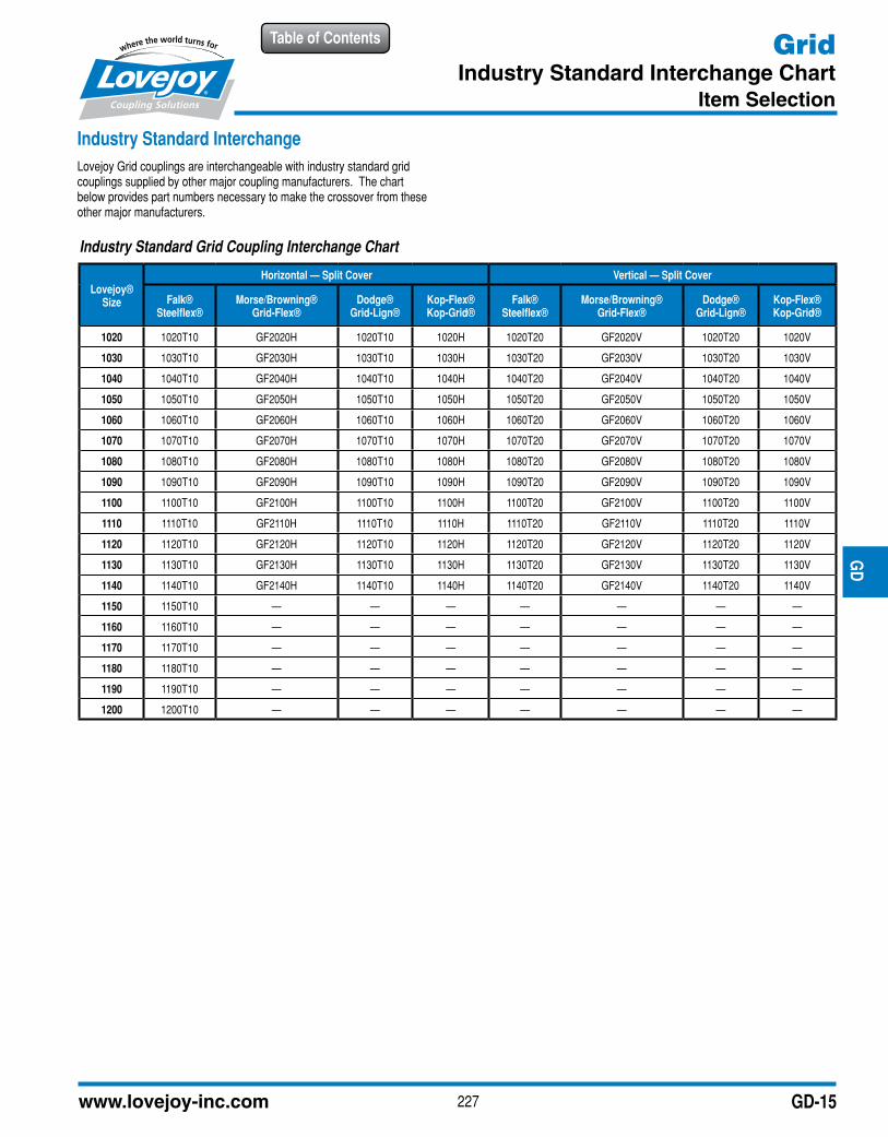
Industry Standard InterchangeLovejoy Grid couplings are interchangeable with industry standard grid couplings supplied by other major coupling manufacturers. The chart below provides part numbers necessary to make the crossover from these other major manufacturers.
JWJI
SC
JSF
MC
GH
PG
DD
TSP
UJ
VSD
RSL
DED
JWJIS
CJ
SFM
CG
HP
GD
DT
SPU
JVSD
RSLD
ED
Industry Standard Grid Coupling Interchange Chart
Lovejoy® Size
Horizontal — Split Cover Vertical — Split Cover
Falk® Steelflex®
Morse/Browning® Grid-Flex®
Dodge® Grid-Lign®
Kop-Flex® Kop-Grid®
Falk® Steelflex®
Morse/Browning® Grid-Flex®
Dodge® Grid-Lign®
Kop-Flex® Kop-Grid®
1020 1020T10 GF2020H 1020T10 1020H 1020T20 GF2020V 1020T20 1020V
1030 1030T10 GF2030H 1030T10 1030H 1030T20 GF2030V 1030T20 1030V
1040 1040T10 GF2040H 1040T10 1040H 1040T20 GF2040V 1040T20 1040V
1050 1050T10 GF2050H 1050T10 1050H 1050T20 GF2050V 1050T20 1050V
1060 1060T10 GF2060H 1060T10 1060H 1060T20 GF2060V 1060T20 1060V
1070 1070T10 GF2070H 1070T10 1070H 1070T20 GF2070V 1070T20 1070V
1080 1080T10 GF2080H 1080T10 1080H 1080T20 GF2080V 1080T20 1080V
1090 1090T10 GF2090H 1090T10 1090H 1090T20 GF2090V 1090T20 1090V
1100 1100T10 GF2100H 1100T10 1100H 1100T20 GF2100V 1100T20 1100V
1110 1110T10 GF2110H 1110T10 1110H 1110T20 GF2110V 1110T20 1110V
1120 1120T10 GF2120H 1120T10 1120H 1120T20 GF2120V 1120T20 1120V
1130 1130T10 GF2130H 1130T10 1130H 1130T20 GF2130V 1130T20 1130V
1140 1140T10 GF2140H 1140T10 1140H 1140T20 GF2140V 1140T20 1140V
1150 1150T10 — — — — — — —
1160 1160T10 — — — — — — —
1170 1170T10 — — — — — — —
1180 1180T10 — — — — — — —
1190 1190T10 — — — — — — —
1200 1200T10 — — — — — — —
228 630-852-0500
Table of Contents
GD-16
GridGrid Coupling Hubs – Inch Bore / Keyway
Item Selection
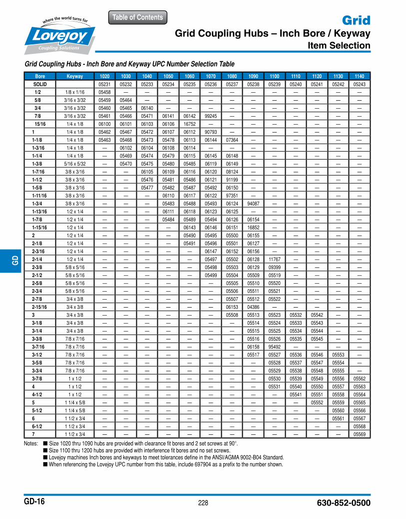
Notes: n Size 1020 thru 1090 hubs are provided with clearance fit bores and 2 set screws at 90°. n Size 1100 thru 1200 hubs are provided with interference fit bores and no set screws. n Lovejoy machines Inch bores and keyways to meet tolerances define in the ANSI/AGMA 9002-B04 Standard. n When referencing the Lovejoy UPC number from this table, include 697904 as a prefix to the number shown.
JWJI
SC
JSF
MC
GH
PG
DD
TSP
UJ
VSD
RSL
DED
JWJIS
CJ
SFM
CG
HP
GD
DT
SPU
JVSD
RSLD
ED
Grid Coupling Hubs - Inch Bore and Keyway UPC Number Selection Table
Bore Keyway 1020 1030 1040 1050 1060 1070 1080 1090 1100 1110 1120 1130 1140
SOLID 05231 05232 05233 05234 05235 05236 05237 05238 05239 05240 05241 05242 05243
1/2 1/8 x 1/16 05458 — — — — — — — — — — — —
5/8 3/16 x 3/32 05459 05464 — — — — — — — — — — —
3/4 3/16 x 3/32 05460 05465 06140 — — — — — — — — — —
7/8 3/16 x 3/32 05461 05466 05471 06141 06142 99245 — — — — — — —
15/16 1/4 x 1/8 06100 06101 06103 06106 16752 — — — — — — — —
1 1/4 x 1/8 05462 05467 05472 06107 06112 90793 — — — — — — —
1-1/8 1/4 x 1/8 05463 05468 05473 05478 06113 06144 07364 — — — — — —
1-3/16 1/4 x 1/8 — 06102 06104 06108 06114 — — — — — — — —
1-1/4 1/4 x 1/8 — 05469 05474 05479 06115 06145 06148 — — — — — —
1-3/8 5/16 x 5/32 — 05470 05475 05480 05485 06119 06149 — — — — — —
1-7/16 3/8 x 3/16 — — 06105 06109 06116 06120 08124 — — — — — —
1-1/2 3/8 x 3/16 — — 05476 05481 05486 06121 91199 — — — — — —
1-5/8 3/8 x 3/16 — — 05477 05482 05487 05492 06150 — — — — — —
1-11/16 3/8 x 3/16 — — — 06110 06117 06122 97351 — — — — — —
1-3/4 3/8 x 3/16 — — — 05483 05488 05493 06124 94087 — — — — —
1-13/16 1/2 x 1/4 — — — 06111 06118 06123 06125 — — — — — —
1-7/8 1/2 x 1/4 — — — 05484 05489 05494 06126 06154 — — — — —
1-15/16 1/2 x 1/4 — — — — 06143 06146 06151 16852 — — — — —
2 1/2 x 1/4 — — — — 05490 05495 05500 06155 — — — — —
2-1/8 1/2 x 1/4 — — — — 05491 05496 05501 06127 — — — — —
2-3/16 1/2 x 1/4 — — — — — 06147 06152 06156 — — — — —
2-1/4 1/2 x 1/4 — — — — — 05497 05502 06128 11767 — — — —
2-3/8 5/8 x 5/16 — — — — — 05498 05503 06129 09399 — — — —
2-1/2 5/8 x 5/16 — — — — — 05499 05504 05509 05519 — — — —
2-5/8 5/8 x 5/16 — — — — — — 05505 05510 05520 — — — —
2-3/4 5/8 x 5/16 — — — — — — 05506 05511 05521 — — — —
2-7/8 3/4 x 3/8 — — — — — — 05507 05512 05522 — — — —
2-15/16 3/4 x 3/8 — — — — — — 06153 04386 — — — — —
3 3/4 x 3/8 — — — — — — 05508 05513 05523 05532 05542 — —
3-1/8 3/4 x 3/8 — — — — — — — 05514 05524 05533 05543 — —
3-1/4 3/4 x 3/8 — — — — — — — 05515 05525 05534 05544 — —
3-3/8 7/8 x 7/16 — — — — — — — 05516 05526 05535 05545 — —
3-7/16 7/8 x 7/16 — — — — — — — 06158 95492 — — — —
3-1/2 7/8 x 7/16 — — — — — — — 05517 05527 05536 05546 05553 —
3-5/8 7/8 x 7/16 — — — — — — — — 05528 05537 05547 05554 —
3-3/4 7/8 x 7/16 — — — — — — — — 05529 05538 05548 05555 —
3-7/8 1 x 1/2 — — — — — — — — 05530 05539 05549 05556 05562
4 1 x 1/2 — — — — — — — — 05531 05540 05550 05557 05563
4-1/2 1 x 1/2 — — — — — — — — — 05541 05551 05558 05564
5 1 1/4 x 5/8 — — — — — — — — — — 05552 05559 05565
5-1/2 1 1/4 x 5/8 — — — — — — — — — — — 05560 05566
6 1 1/2 x 3/4 — — — — — — — — — — — 05561 05567
6-1/2 1 1/2 x 3/4 — — — — — — — — — — — — 05568
7 1 1/2 x 3/4 — — — — — — — — — — — — 05569
229www.lovejoy-inc.com
Table of Contents
GD-17
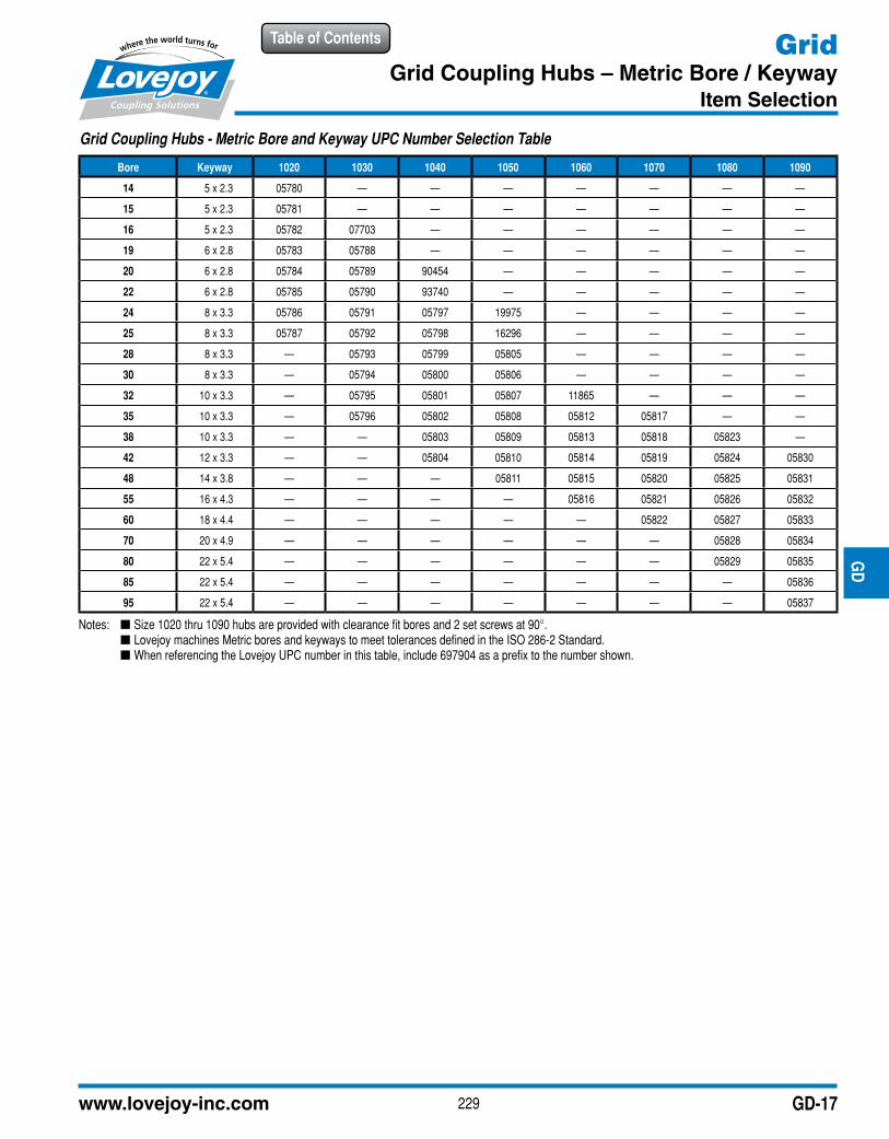
GridGrid Coupling Hubs – Metric Bore / Keyway
Item Selection
Notes: n Size 1020 thru 1090 hubs are provided with clearance fit bores and 2 set screws at 90°. n Lovejoy machines Metric bores and keyways to meet tolerances defined in the ISO 286-2 Standard. n When referencing the Lovejoy UPC number in this table, include 697904 as a prefix to the number shown.
JWJI
SC
JSF
MC
GH
PG
DD
TSP
UJ
VSD
RSL
DED
JWJIS
CJ
SFM
CG
HP
GD
DT
SPU
JVSD
RSLD
ED
Grid Coupling Hubs - Metric Bore and Keyway UPC Number Selection Table
Bore Keyway 1020 1030 1040 1050 1060 1070 1080 1090
14 5 x 2.3 05780 — — — — — — —
15 5 x 2.3 05781 — — — — — — —
16 5 x 2.3 05782 07703 — — — — — —
19 6 x 2.8 05783 05788 — — — — — —
20 6 x 2.8 05784 05789 90454 — — — — —
22 6 x 2.8 05785 05790 93740 — — — — —
24 8 x 3.3 05786 05791 05797 19975 — — — —
25 8 x 3.3 05787 05792 05798 16296 — — — —
28 8 x 3.3 — 05793 05799 05805 — — — —
30 8 x 3.3 — 05794 05800 05806 — — — —
32 10 x 3.3 — 05795 05801 05807 11865 — — —
35 10 x 3.3 — 05796 05802 05808 05812 05817 — —
38 10 x 3.3 — — 05803 05809 05813 05818 05823 —
42 12 x 3.3 — — 05804 05810 05814 05819 05824 05830
48 14 x 3.8 — — — 05811 05815 05820 05825 05831
55 16 x 4.3 — — — — 05816 05821 05826 05832
60 18 x 4.4 — — — — — 05822 05827 05833
70 20 x 4.9 — — — — — — 05828 05834
80 22 x 5.4 — — — — — — 05829 05835
85 22 x 5.4 — — — — — — — 05836
95 22 x 5.4 — — — — — — — 05837
230 630-852-0500
Table of ContentsJW
JIS
CJ
SFM
CG
HP
GD
DT
SPU
JVS
DR
SLD
ED
JWJIS
CJ
SFM
CG
HP
GD
DT
SPU
JVSD
RSLD
ED
GD-18
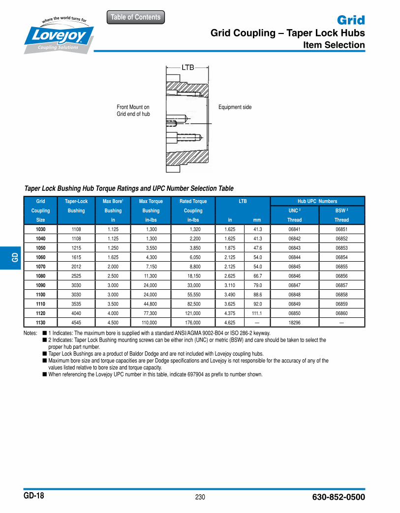
GridGrid Coupling – Taper Lock Hubs
Item Selection
Notes: n 1 Indicates: The maximum bore is supplied with a standard ANSI/AGMA 9002-B04 or ISO 286-2 keyway. n 2 Indicates: Taper Lock Bushing mounting screws can be either inch (UNC) or metric (BSW) and care should be taken to select the
proper hub part number. n Taper Lock Bushings are a product of Baldor Dodge and are not included with Lovejoy coupling hubs. n Maximum bore size and torque capacities are per Dodge specifications and Lovejoy is not responsible for the accuracy of any of the
values listed relative to bore size and torque capacity. n When referencing the Lovejoy UPC number in this table, indicate 697904 as prefix to number shown.
Front Mount on Grid end of hub
Equipment side
Taper Lock Bushing Hub Torque Ratings and UPC Number Selection Table
Grid Taper-Lock Max Bore1 Max Torque Rated Torque LTB Hub UPC Numbers
Coupling Bushing Bushing Bushing Coupling UNC 2 BSW 2
Size in in-lbs in-lbs in mm Thread Thread
1030 1108 1.125 1,300 1,320 1.625 41.3 06841 06851
1040 1108 1.125 1,300 2,200 1.625 41.3 06842 06852
1050 1215 1.250 3,550 3,850 1.875 47.6 06843 06853
1060 1615 1.625 4,300 6,050 2.125 54.0 06844 06854
1070 2012 2.000 7,150 8,800 2.125 54.0 06845 06855
1080 2525 2.500 11,300 18,150 2.625 66.7 06846 06856
1090 3030 3.000 24,000 33,000 3.110 79.0 06847 06857
1100 3030 3.000 24,000 55,550 3.490 88.6 06848 06858
1110 3535 3.500 44,800 82,500 3.625 92.0 06849 06859
1120 4040 4.000 77,300 121,000 4.375 111.1 06850 06860
1130 4545 4.500 110,000 176,000 4.625 — 18296 —
231www.lovejoy-inc.com
JWJI
SC
JSF
MC
GH
PG
DD
TSP
UJ
VSD
RSL
DED
JWJIS
CJ
SFM
CG
HP
GD
DT
SPU
JVSD
RSLD
EDTable of Contents
GD-19
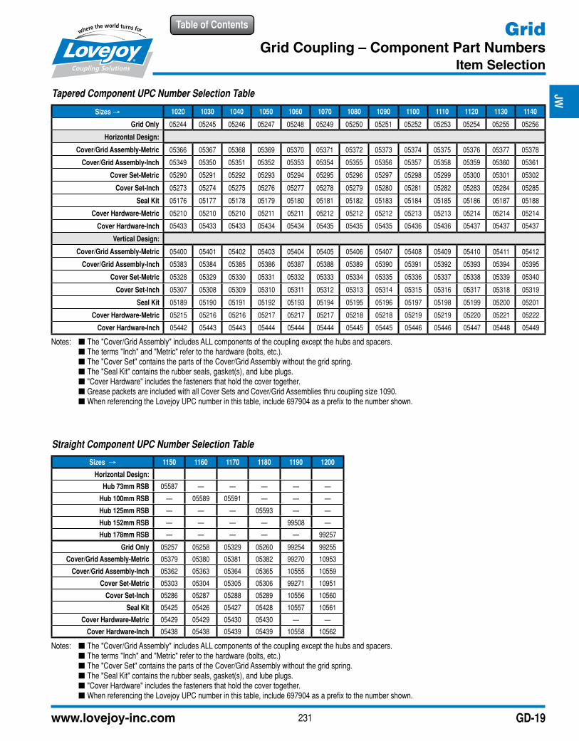
GridGrid Coupling – Component Part Numbers
Item Selection
Tapered Component UPC Number Selection Table
Sizes → 1020 1030 1040 1050 1060 1070 1080 1090 1100 1110 1120 1130 1140
Grid Only 05244 05245 05246 05247 05248 05249 05250 05251 05252 05253 05254 05255 05256
Horizontal Design:
Cover/Grid Assembly-Metric 05366 05367 05368 05369 05370 05371 05372 05373 05374 05375 05376 05377 05378
Cover/Grid Assembly-Inch 05349 05350 05351 05352 05353 05354 05355 05356 05357 05358 05359 05360 05361
Cover Set-Metric 05290 05291 05292 05293 05294 05295 05296 05297 05298 05299 05300 05301 05302
Cover Set-Inch 05273 05274 05275 05276 05277 05278 05279 05280 05281 05282 05283 05284 05285
Seal Kit 05176 05177 05178 05179 05180 05181 05182 05183 05184 05185 05186 05187 05188
Cover Hardware-Metric 05210 05210 05210 05211 05211 05212 05212 05212 05213 05213 05214 05214 05214
Cover Hardware-Inch 05433 05433 05433 05434 05434 05435 05435 05435 05436 05436 05437 05437 05437
Vertical Design:
Cover/Grid Assembly-Metric 05400 05401 05402 05403 05404 05405 05406 05407 05408 05409 05410 05411 05412
Cover/Grid Assembly-Inch 05383 05384 05385 05386 05387 05388 05389 05390 05391 05392 05393 05394 05395
Cover Set-Metric 05328 05329 05330 05331 05332 05333 05334 05335 05336 05337 05338 05339 05340
Cover Set-Inch 05307 05308 05309 05310 05311 05312 05313 05314 05315 05316 05317 05318 05319
Seal Kit 05189 05190 05191 05192 05193 05194 05195 05196 05197 05198 05199 05200 05201
Cover Hardware-Metric 05215 05216 05216 05217 05217 05217 05218 05218 05219 05219 05220 05221 05222
Cover Hardware-Inch 05442 05443 05443 05444 05444 05444 05445 05445 05446 05446 05447 05448 05449
Notes: n The "Cover/Grid Assembly" includes ALL components of the coupling except the hubs and spacers. n The terms "Inch" and "Metric" refer to the hardware (bolts, etc.). n The "Cover Set" contains the parts of the Cover/Grid Assembly without the grid spring. n The "Seal Kit" contains the rubber seals, gasket(s), and lube plugs. n "Cover Hardware" includes the fasteners that hold the cover together. n Grease packets are included with all Cover Sets and Cover/Grid Assemblies thru coupling size 1090. n When referencing the Lovejoy UPC number in this table, include 697904 as a prefix to the number shown.
Notes: n The "Cover/Grid Assembly" includes ALL components of the coupling except the hubs and spacers. n The terms "Inch" and "Metric" refer to the hardware (bolts, etc.) n The "Cover Set" contains the parts of the Cover/Grid Assembly without the grid spring. n The "Seal Kit" contains the rubber seals, gasket(s), and lube plugs. n "Cover Hardware" includes the fasteners that hold the cover together. n When referencing the Lovejoy UPC number in this table, include 697904 as a prefix to the number shown.
Straight Component UPC Number Selection Table
Sizes → 1150 1160 1170 1180 1190 1200
Horizontal Design:
Hub 73mm RSB 05587 — — — — —
Hub 100mm RSB — 05589 05591 — — —
Hub 125mm RSB — — — 05593 — —
Hub 152mm RSB — — — — 99508 —
Hub 178mm RSB — — — — — 99257
Grid Only 05257 05258 05329 05260 99254 99255
Cover/Grid Assembly-Metric 05379 05380 05381 05382 99270 10953
Cover/Grid Assembly-Inch 05362 05363 05364 05365 10555 10559
Cover Set-Metric 05303 05304 05305 05306 99271 10951
Cover Set-Inch 05286 05287 05288 05289 10556 10560
Seal Kit 05425 05426 05427 05428 10557 10561
Cover Hardware-Metric 05429 05429 05430 05430 — —
Cover Hardware-Inch 05438 05438 05439 05439 10558 10562