1 Journal of Information Systems [email protected] [email protected].
Upload
raajksharmaCategory
view
2.797download
401
J IS JAPANESE I N DUSTR IAL STANDARD
Translated and Published by Japanese Standards Association
Dimensions, mass and permissible variations of hot rolled steel sections
I C s 77.140.70
Reference number : JIS G 3192 : 2005 (E)
PROTECTED BY COPYRIGHT 29 S
G 3192 : 2005
Foreword
This translation has been made based on the original Japanese Industrial Standard revised by the Minister of Economy, Trade and Industry through deliberations a t the Japanese Industrial Standards Committee, as the result of proposal for revision of Japanese Industrial Standard submitted by The Japan Iron and Steel Federation (JISF) with the draft being attached, based on the provision of Article 12 Clause 1 of the Industrial Standardization Law applicable to the case of revision by the provision of Article 14. Consequently JIS G 3192 : 2000 is replaced with this Standard. This revision has been made based on IS0 657-1 : 1989 Hot-rolled steel sections-Part 1: Equal-leg angles-Dim,en,.sions, I S 0 657-2 : 1989 Hot-rolled steel sections-Part 2: Unequal-leg angles-Dimensions, I S 0 657-5 : 1976 Hot-rolled steel sections-Part 5: Equal-leg angles and unequal-leg angles-Tolerances for metric and inch series, I S 0 657-1 1 : 1980 Hot-rolled steel sections-Part 11: Sloping flange channel sections (Met- ric series)-Dimensions and sectional properties, IS0 657-15 : 1980 Hot-rolled steel sec- tions-Part 15: Sloping flange beam sections (Metric series)-Dimensions and sectional properties, IS0 657-16 : 1980 Hot-rolled steel sections-Part 16: Sloping flange column sectiom (metric series)-Dim,ensions and sectional properties, IS0 657-18 : 1980 Hot-rolled steel sections-Part 18: L sections for shipbuilding (metric series)-Dimensions, sectional properties and tolerances, IS0 657-19 : 1980 Hot-rolled steel sections-Part 19: Bulb f lats (metric series-Dimensions, sectional properties and tolerances and IS0 657-21 : 1983 Hot-rolled steel section,s-Part 21: T-section,s with equal depth, an,d flange width,-Dirn,en- sions for the purposes of making it easier to compare this Standard with International Standards; to prepare Japanese Industrial Standard conforming with International Standards; and to propose drafts of International Standards which are based on Japa- nese Industrial Standard. Attention is drawn to the possibility that some parts of this Standard may conflict with a patent right, application for a patent after opening t o the public, utility model right or application for registration of utility model after opening to the public which have technical properties. The relevant Minister and the Japanese Industrial Standards Committee are not responsible for identifying the patent right, application for a patent after opening to the public, utility model right or application for registration of utility model after opening to the public which have the said technical properties.
Date of Establishment: 1954-07-30
Date of Revision: 2005-07-20
Date of Public Notice in Official Gazette: 2005-07-20
Investigated by: Japanese Industrial Standards Committee
Standards Board
Technical Committee on Iron and Steel
JIS G 3192 : 2005, First English edit ion published in 2006-03
Translated aiid published by: Japanese Standards Association 4-1-24, Altasaka, Minato-ku, Tokyo, 107-5440 JAPAN
In the event of any doubts arising as to the contents, the original JIS is to be the final authority.
O JSA 2006 All rights reserved. Unless otherwise specified, no part of this publication inay be reproduced or utilized iii any form or by a n y ineans, electronic or mechanical, including pliotocopying and microfilin, without permission in writing froin the piiblisher.
Printed in Japan KWAT
PROTECTED BY COPYRIGHT
--```,`,,```,`,`,``,`,`,````,-`-`,,`,,`,`,,`---

Contents
G 3192 : 2005
Page Introduction ..................................................................................................................
Scope ....................................................................................................................
Normative reference ..........................................................................................
Sectional shape and classification ...................................................................
Expression of size ..............................................................................................
Standard dimensions .........................................................................................
Shape and dimensional tolerances ..................................................................
Mass .....................................................................................................................
Tolerance on mass .............................................................................................
Appearance ..........................................................................................................
Annex 1 (normative)
Annex 2 (normative)
Annex 3 (normative)
Annex 4 (normative)
Annex 5 (normative)
Annex 6 (normative)
Annex 7 (normative)
Annex 8 (normative)
Annex 9 (normative)
Hot-rolled steel sections-Part 1: Equal-leg angles- Dimensions ............................................................................
Hot-rolled steel sections-Part 2: Unequal-leg angles-Dimensions .............................................................
Hot-rolled steel sections-Part 3: Equal-leg angles and unequal-leg angles-Tolerances .................................
Hot-rolled steel sections-Part 4: Sloping flange channel sections-Dimensions and sectional properties ..............................................................................
Hot-rolled steel sections-Part 5: Sloping flange I-sections-Dimensions and sectional properties ............
Hot-rolled steel sections-Part 6: Sloping flange column sections-Dimensions and sectional properties ..............................................................................
Hot-rolled steel sections-Part 7: L-sections for shipbuilding-Dimensions, sectional properties and tolerances ..............................................................................
Hot-rolled steel sections-Part 8: Bulb flats- Dimensions. sectional properties and tolerances ............
Hot-rolled steel sections-Part 9: T-sections with equal depth and flange width-Dimensions ....................
Annex 10 (informative) Comparison table between JIS and corresponding International Standards .................................................
1
1
2
2
3
3
3
6
7
7
19
24
30
33
35
37
39
43
47
49
PROTECTED BY COPYRIGHT
--```,`,,```,`,`,``,`,`,````,-`-`,,`,,`,`,,`---
JAPANESE INDUSTRIAL STANDARD JIS G 3192 : 2005
Dimensions, mass and permissible variations of hot rolled steel sections
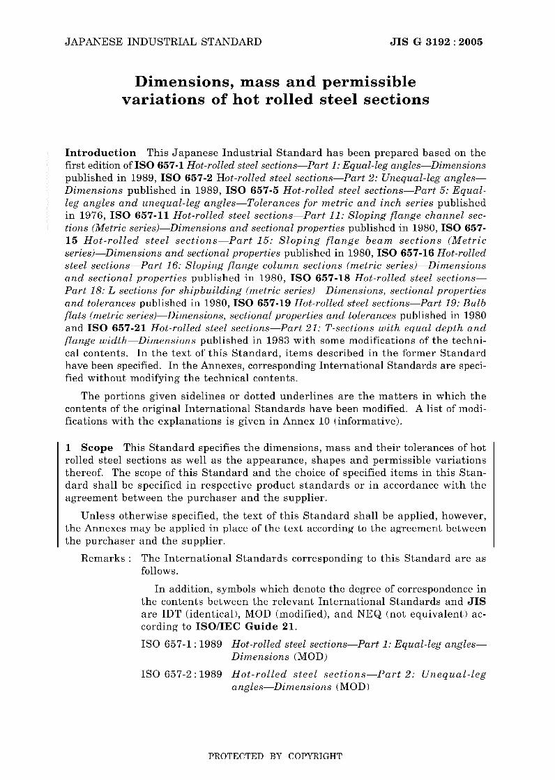
Introduction This Japanese Industrial Standard has been prepared based on the first edition of IS0 657-1 Hot-rolled steel sections-Part 1: Equal-leg angles-Dimensions published in 1989, IS0 657-2 Hot-rolled steel sections-Part 2: Unequal-leg angles- Dimensions published in 1989, IS0 657-5 Hot-rolled steel sections-Part 5: Equal- leg angles and unequal-leg angles-Tolerances for metric and inch series published in 1976, IS0 657-11 Hot-rolled steel sections-Part 11: Sloping flange channel sec- tions (Metric series)-Dimensions and sectional properties published in 1980, IS0 657- 15 Hot-ro l led steel sections-Part 15: S l o p i n g f l a n g e b e a m sect ions (Metr ic series)-Dimensions and sectional properties published in 1980, IS0 657-16 Hot-rolled steel sections-Part 16: Sloping flange column sections (metric series)-Dimensions and sectional properties published in 1980, IS0 657-18 Hot-rolled steel sections- Part 18: L sections for shipbuilding (metric series)-Dimensions, sectional properties and tolerances published in 1980, IS0 657-19 Hot-rolled steel sections-Part 19: Bulb flats (metric series)-Dimensions, sectional properties and tolerances published in 1980 and IS0 657-21 Hot-rolled steel sections-Part 21: T-sections with equal depth and flange width-Dimensions published in 1983 with some modifications of the techni- cal contents. In the text of this Standard, items described in the former Standard have been specified. In the Annexes, corresponding International Standards are speci- fied without modifying the technical contents.
The portions given sidelines or dotted underlines are the matters in which the contents of the original International Standards have been modified. A list of modi- fications with the explanations is given in Annex 10 (informative).
1 Scope This Standard specifies the dimensions, mass and their tolerances of hot rolled steel sections a s well a s the appearance, shapes and permissible variations thereof. The scope of this Standard and the choice of specified items in this Stan- dard shall be specified in respective product standards or in accordance with the agreement between the purchaser and the supplier.
Unless otherwise specified, the text of this Standard shall be applied, however, the Annexes may be applied in place of the text according t o the agreement between the purchaser and the supplier.
The International Standards corresponding to this Standard are as follows.
Remarks :
In addition, symbols which denote the degree of correspondence in the contents between the relevant International Standards and JIS are IDT (identical), MOD (modified), and NEQ (not equivalent) ac- cording to ISO/IEC Guide 21.
I S 0 657-1 : 1989 Hot-rolled steel sections-Part 1: Equal-leg angles- Dimensions (MOD)
I S 0 657-2 : 1989 Hot-rol led steel sections-Part 2: U n e q u a l - l e g angles-Dimensions (MOD)
PROTECTED BY COPYRIGHT
--```,`,,```,`,`,``,`,`,````,-`-`,,`,,`,`,,`---

2 G 3192 : 2005
IS0 657-5 : 1976 Hot-rolled steel sections-Part 5: Equal-leg angles und unequul-leg ungles-Tolerunces for metric und inch series (MOD)
IS0 657-1 1 : 1980 Hot-rolled steel sections-Part 11: Sloping flange channel sections (Metric series)-Dimensions and sectional properties (MOD)
IS0 657-15 : 1980 Hot-rolled steel sections-Part 15: Sloping flange beurn sections (Metric series)-Dimensions a n d sectional properties (MOD)
IS0 657-16 : 1980 Hot-rolled steel sections-Part 16: Sloping flange column sections (metric series)-Dimensions and sectional properties (MOD)
IS0 657-18 : 1980 Hot-rolled steel sections-Part 18: L sections for shipbuilding (metric series)-Dimensions, sectionul properties and tolerances (MOD)
IS0 657-19 : 1980 Hot-rolled steel sections-Part 19: Bulb flats (metric series)-Dimensions, sectional properties and tol- erances (MOD)
IS0 657-21 : 1983 Hot-rolled steel sections-Purt 21: T-sections with equal depth and flange width-Dimensions (MOD)
2 Normative reference The following standard contains provisions which, through reference in this text, constitute provisions of this Standard. The most recent edi- tion of the standard indicated below shall be applied.
JIS Z 8401 Guide to the rounding of numbers
3 Sectional shape and classification and their classification shall be as given in table 1.
The sectional shapes of the steel sections
Table 1 Sectional shape of steel sections and classification
I Classification I Sectional shape diagram I
Unequal-legs and unequal thickness
I-sections
PROTECTED BY COPYRIGHT

3 G 3192 : 2005
Table 1 (concluded)
Classification I Sectional shape diagram
Channels
Bulb flats i T-sections
H-sections
4 Expression of size The size of the steel sections shall be expressed by each sectional dimension in millimetre and the length in metre. According to the prod- uct shape, as a rule, dimensions are expressed by items among leg length (A, B ) , depth ( H ) and thickness ( t , ti , t 2 ) of each section, and the length of the purchased product. The thickness of channels in attached table 5 can be expressed only by t i in ti and ta.
5 Standard dimensions The standard dimensions shall be as follows:
a) The standard sectional dimensions of the steel sections shall be as given in attached tables 1 to 8.
b) The standard lengths of the steel sections shall be as given in table 2.
Table 2 Standard length
Unit: m
6.0 7.0 8.0 9.0 10.0 11.0 12.0 13.0 14.0 15.0
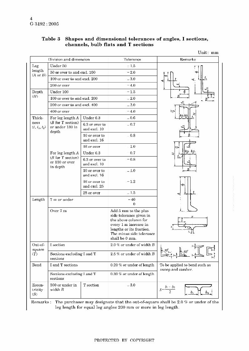
6 Shape and dimensional tolerances The shape and dimensional tolerances of the steel sections shall be as follows. The tolerances of the steel sections other than those specified in a) and b) shall be agreed upon between the purchaser and the supplier.
a) The shapes and dimensional tolerances of the angles, I-sections, channels, bulb flats and T-sections shall be as given in table 3.
b) The shape and dimensional tolerances of the H-sections shall be as given in table 4. The tolerances on squareness, however, shall be applied on the request of the purchaser.
PROTECTED BY COPYRIGHT
--```,`,,```,`,`,``,`,`,````,-`-`,,`,,`,`,,`---
4 G 3192 : 2005
300 or under in width B
Table 3 Shapes and dimensional tolerances of angles, I sections, channels, bulb flats and T sections
T section
Unit: mm
Division and dimension Tolerance
i 1.5
Remarks
Leg length (A or BI
Under 50
50 or over to and excl. 100 + 2.0
i 3.0 100 or over to and excl. 200
200 or over i 4.0
Depth (Hl
i 1.5 Under 100
100 or over to and excl. 200 i 2.0
i 3.0 200 or over to and excl. 400
400 or over i 4.0
Thick- ness (t , ti, t 2 )
For leg length A I Under 6.3 i 0.6 - - (B for T section) or under 130 in depth
i 0.7
I 0.8 10 or over to
16 or over I l . O
For leg length A I Under 6.3 + 0.7
i 0.8
i 1.0 10 or over to
16 or over to and excl. 25
i 1.2
I 25 or over i 1.5
Length 7 m or under + 40 0
Over 7 m Add 5 mm to the plus side tolerance given in the above column for every 1 m increase in lengths or its fraction. The minus side tolerance shall be 0 mm.
Out-of- square (T)
I section 2.0 '70 or under of width B
Sections excluding I and T sections
2.5 76 or under of width B
Bend I and T sections 0.20 '70 or under of length To be applied to bend such as sweep and camber.
Sections excluding I and T sections
0.30 '70 or under of length
Eccen- tricity (S?
i 3.0
Remarks : The purchaser may designate that the out-of-square shall be 2.0 9% or under of the leg length for equal leg angles 200 mm or more in leg length.
PROTECTED BY COPYRIGHT
--```,`,,```,`,`,``,`,`,````,-`-`,,`,,`,`,,`---

5 G 3192 : 2005
Table 4 Shapes and dimensional tolerances of H-sections
Unit: mm
Division and dimension Tolerance Remarks
Width (B) Under 100 in nominal width = 2.0
100 or over to and excl. 200 in nominal width
= 2.5
200 or over in nominal width = 3.0
Depth (H) Under 400 in nominal depth = 2.0
- 3.0 400 or over to and excl. 600 in nominal depth
600 or over in nominal depth
Under 16
- 4.0
Flange ( t 2 )
= 1.0
16 or over to and excl. 25 = 1.5
25 or over to and excl. 40 = 1.7
40 or over = 2.0
Web (ti)
Under 16 = 0.7
16 or over to and excl. 25
25 or over to and excl. 40
40 or over
7 m or under
= 1.0
= 1.5
= 2.0
+ 40 O
Add 5 mm to the plus side tolerance given in the above column for every 1 m increase in length or its fraction. The minus side tolerance shall be O mm.
Length
Over 7 m
Out-of- square (TI
300 or under in nominal depth 1.0 % or under of width B, provided that 1.5 mm is the minimum.
1.2 % or under of width B, provided that 1.5 mm is the minimum.
Over 300 in nominal depth
Bend 300 or under in nominal depth 0.15 5% or under of length To be applied to bend such as sweep and camber. Over 300 in nominal depth 0.10 or under of length
Eccen- tricity (SI
= 2.5 300 or under in nominal depth and 200 or under in nominal width
Over 300 in nominal depth and over 200 in nominal width
3.5
Concavity of web (W)
Under 400 in nominal depth
400 or over to and excl. 600 in nominal depth
2.0 or under
2.5 or under
600 or over in nominal depth 3.0 or under Sectional squareness ( e ) 1.6 % or under of width B
or of depth H , provided that 3.0 mm is the mini- mum.
PROTECTED BY COPYRIGHT
--```,`,,```,`,`,``,`,`,````,-`-`,,`,,`,`,,`---
6 G 3192 : 2005
Calculation method
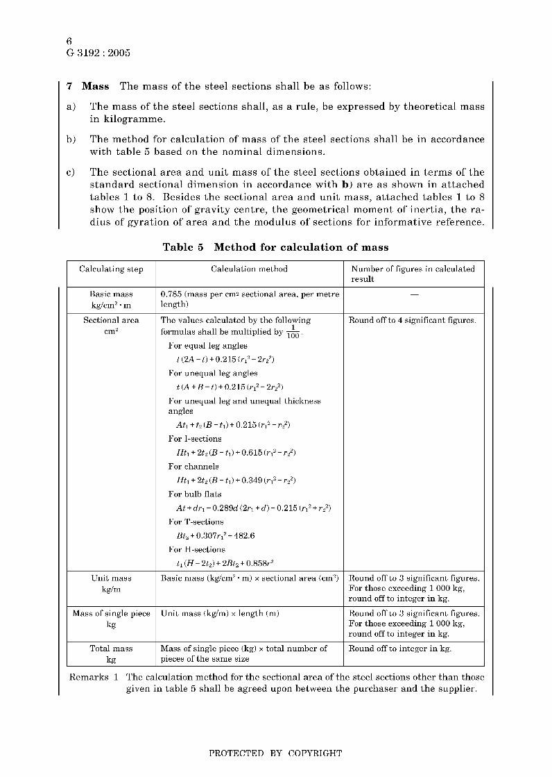
7 Mass
a)
The mass of the steel sections shall be as follows:
The mass of the steel sections shall, as a rule, be expressed by theoretical mass in kilogramme.
The method for calculation of mass of the steel sections shall be in accordance with table 5 based on the nominal dimensions.
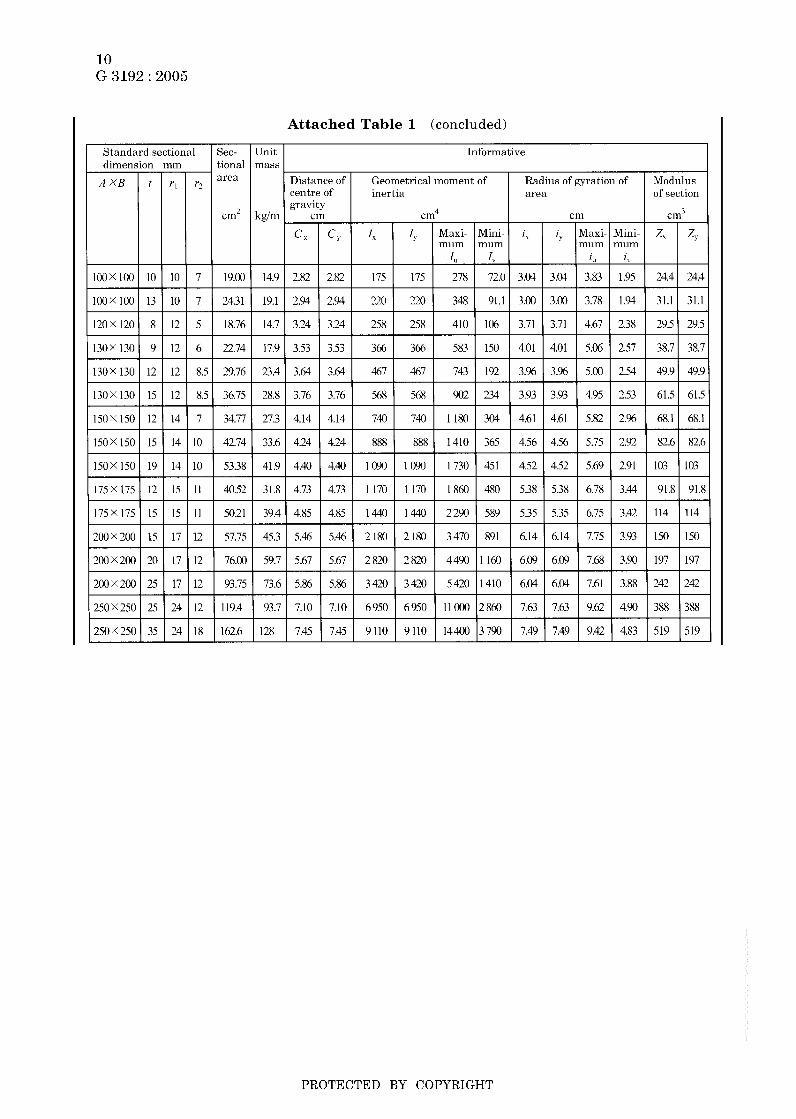
The sectional area and unit mass of the steel sections obtained in terms of the standard sectional dimension in accordance with b) are as shown in attached tables 1 to 8. Besides the sectional area and unit mass, attached tables 1 to 8 show the position of gravity centre, the geometrical moment of inertia, the ra- dius of gyration of area and the modulus of sections for informative reference.
b)
c)
Number of figures in calculated result
Table 5 Method for calculation of mass
0.785 (mass per cm2 sectional area, per metre length)
Calculating step
- Basic mass kg/cm2 * m
Basic mass (kg/cm2 * m) x sectional area (cm2)
Sectional area cm2
Round off to 3 significant figures. For those exceeding 1 O00 kg, round off t o integer in kg.
Unit mass kglm
Mass of single piece kg
Total mass kg
formulas shall be multiplied by m. 1
For equal leg angles t (2A - t ) + 0.215 (rL2 - 2r&
For unequal leg angles t (A+B-t)+0.215(ri2-2rz2)
For unequal leg and unequal thickness angles
Ati + ti ( B - ti) + 0.215 (ri2 - rz2) For I-sections
Hti + 2tz (B - t i ) + 0.615 (ri2 - rzz)
For channels
Hti + 2t2 ( B - ti) + 0.349 (riZ - r2’) For bulb flats
At+dr1+0.289d(2ri+d)-0.215 (rl2+rz2)
For T-sections
Bt2 + 0.307rii + 482.6
For H-sections
t i (H - 2t2) + 2Bt2 + 0.858rz
Unit mass (kg/m) x length (m) Round off to 3 significant figures. For those exceeding 1 O00 kg, round off t o integer in kg.
Mass of single piece (kg) x total number of pieces of the same size
Round off to integer in kg.
Remarks 1 The calculation method for the sectional area of the steel sections other than those given in table 5 shall be agreed upon between the purchaser and the supplier.
PROTECTED BY COPYRIGHT

7 G 3192 : 2005
2 The symbols which are used for the calculation of the sectional area stand for the sectional dimensions of the steel section, and the relation of the symbols t o the respective parts of the section is shown in attached tables 1 to 8.
3 The rounding off of the numerical values shall be in accordance with Rule A in JIS Z 8401.
8 Tolerance on mass When applying of the mass tolerances for steel sections are requested by the purchaser, they shall conform to table 6. In this case, the tol- erances on mass shall be expressed by the quotient in percentage tha t the differ- ence between the theoretical mass and actual mass is divided by the theoretical mass.
Table 6 Tolerances on mass
Thickness I Tolerance I Remarks
Under 10 mm a) Thicker nominal values shall be applied. b) To be applied to one lot of the same size (i t or over).
When the number of pieces corresponding to 1 t does not amount to 10, it shall be applied to each lot of 10 or more pieces.
10 mm or over
9 Appearance The appearance of the steel sections shall be as follows:
The steel sections shall be free from defects tha t are detrimental to practical use.
In the case where there are some harmful defects on the surface of the steel sections, the manufacturer may remove or repair the defects by grinding or welding. In this case, the operation shall be as follows:
1) Conditioning with grinder
1.1) The sectional dimensions of the steel sections after conditioning shall fall within the range of the tolerances. When approved by the purchaser, how- ever, this restriction may be applied flexibly according to its application.
1.2) The conditioned parts of the steel sections shall be finished neatly, and the boundary between the repaired portions and as rolled surface shall be smoothly finished.
2) Repair by welding
2.1) The harmful defects of the steel sections shall be repaired by welded overlay after complete removal by means of appropriate method such as chipping or grinding.
2.2) The depth of the defect-removed portion previous to repair by welding shall be not more than 30 % of the nominal thickness. For the toe of the flange of the steel sections, however, the depth shall fall within the nominal thick- ness of the flange from the edge (12 mm max.).
2.3) The repaired area by welding shall fall within 2 % of the whole surface area of the steel sections.
PROTECTED BY COPYRIGHT
--```,`,,```,`,`,``,`,`,````,-`-`,,`,,`,`,,`---

8 G 3192 : 2005
2.5
2.6
2.4) The weld repairing shall be carried out by suitable means according to the kind of steel products.
The welded part of the steel sections shall be free from undercut or over- laps around the fringe of welds. The reinforcement of weld shall be a t least 1.5 mm in height from the rolled surface, and this shall be removed by chipping, grinding, etc. and smoothly finished as high as the rolled surface.
The heat-treated steel sections themselves shall be heat-treated once again after the repair by welding.
PROTECTED BY COPYRIGHT

9 G 3192 : 2005
Attached Table 1 Standard sectional dimensions, sectional area, unit mass and sectional properties of equal-leg angles
Geometrical moment of inertia Z=ai2
Radius of gyration of area i=-
Modulus of section z= lie
( a = sectional area)
PROTECTED BY COPYRIGHT
--```,`,,```,`,`,``,`,`,````,-`-`,,`,,`,`,,`---
10 G 3192 : 2005
7.45 7.45 9110 9 110 14400 3790 7.49 7.49 9.42 4.83 519
Attached Table 1 (concluded)
519
- Unit mass
kglm
14.9
19.1
14.7
17.9 -
23.4
2x3
27.3
33.6 -
41.9
31.8
39.4
45.3
59.7
- -
73.6
93.7
128 -
PROTECTED BY COPYRIGHT
--```,`,,```,`,`,``,`,`,````,-`-`,,`,,`,`,,`---

11 G 3192 : 2005
Unit mnss
Attached Table 2
i%,
Informative
Distance of Geometrical moment o f Radius of gyration of tan (x Modulus centre of inertia area of section
Standard sectional dimensions, sectional area, unit mass and sectional properties of unequal-leg angles
mm
rl
8.5
10
I O
10
10
10
10
10
12
12
12
12
12
Geometrical moment of inertia I=&
Radius of gyration of a rea
Modulus of section z= lie
i=*
r2
6
5
7
5
7
7
7
7
6
8.5
6
8.5
8.5
Standard sectional
IOOX 75
125X 75
125X 75
125X 75
125x 90
125X W
150X 90
150X 90
150X100
150x100
150x100
dimension
10
7
10
13
10
13
9
12
9
12
15
21.5
17.1
5.07 2.10 619 167 685 102 4.76 2.47 5.00 1.93
4.76 2.30 502 181 579 104 4.79 2.88 5.15 2.18
- Sec- tional area
cm2
- 14.04
22.4
27.7
11.87
4.88 2.41 642 228 738 132 4.74 2.83 5.09 2.15 0.435 63.4 30.1
5.00 2.53 782 276 8Y7 161 4.71 2.80 5.04 2.14 0.431 78.2 37.C
16.50
13.62
1Y.00
24.3 1
-
-
20.50
26.26
20.94 -
27.36
21.84
28.56
3525 -
I I I I I I I I I I I I I
0.362 26.1 103
0.357 36.1 14.1
0352 46.1 17.9 t 0.505 372 20.3
0.501 47.5 25.9
0.361 48.2 19.0
0.357 62.3 24.3 # 0.439 49.1 23.5
PROTECTED BY COPYRIGHT

12 G 3192 : 2005
Attached Table 3 Standard sectional dimensions, sectional area, unit mass and sectional properties of unequal-leg and unequal thickness angles
dime A x B
Geometrical moment of inertia I z a ?
Radius of gyration of area
Modulus of section Z=Iie
i=m
(a = sectional area) - t,
!OOX 9c
!5OX 91
!50X 9(
1oox 9(
1oox Y(
ion mm
12 rl
14 14
15 17
16 17
16 19
17 19
17 22
18 24
crn2 kgín
45.:
53.1 - -
V Y \ I
Informative
PROTECTED BY COPYRIGHT

13 G 3192 : 2005
tional mass area I
Attached Table 4 Standard sectional dimensions, sectional area, unit mass and sectional properties of I sections
Distance of Geometrical Radius of Modulus centre of moment of inertia gyration of area of section
Geometrical moment of inertia I=ui’
Radius of gyration of a rea
Modulus of section z= I le
( a = sectional a rea)
;=-
10OX 75
125X 75
150X 75
15OX 125
180x100
Y
gravity cm’ kgím cm cm4 cm cm3
c, c-, 1, 11’ 1, 1 ) z, ZY
5 8 7 3.5 16.43 12.9 O O 28 1 47.3 4.14 1.70 56.2 12.6
5.5 9.5 9 4.5 20.45 16.1 O 0 538 57.5 5.13 1.68 86.0 15.3
5.5 9.5 Y 4.5 21.83 17.1 O O 819 57.5 6.12 1.62 109 15.3
8.5 14 13 6.5 46.15 36.2 O O 1760 385 6.18 2.89 235 61.6
6 10 10 5 30.06 23.6 O O 1 670 138 7.45 2.14 186 27.5
I Y
200x100
200x150
250X 125
Standard sectional dimension I Sec- I Unit I Informative
7 10 10 5 33.06 26.0 O O 2 170 138 8 11 2 0 5 217 27.7
Y 16 15 7.5 64.16 50.4 O O 4460 753 8.34 3.43 446 100
7 5 12.5 12 6 48.79 38.3 O O 5 180 337 10.3 2.63 414 53.9
mm
250x125
300X 150
300x150
10 19 21 10.5 70.73 55.5 0 O 7310 538 10.2 2.76 585 86.0
8 13 12 6 61.58 48.3 0 O 9480 588 12.4 3.09 632 78.4
10 18.5 19 9.5 83.47 65.5 O O 12700 886 12.3 3.26 849 118
300x150
350X 150
11.5 22 23 11.5 97.88 76.8 0 O 14700 1080 12.2 3.32 978 143
9 15 13 6.5 74.58 58.5 0 O 15 200 702 14.3 3.07 870 93.5
3SOX I50
400x150
400x150
450x175
12 24 25 12.5 111.1 87.2 O O 22400 1180 14.2 3.26 1280 158
10 18 17 8.5 91.73 72.0 O O 24 100 864 16.2 3.07 I 2 0 0 115
12.5 25 27 13.5 122.1 95.8 0 0 31 700 I 2 4 0 16.1 3.18 1 580 165
11 20 19 9.5 116.8 91.7 O O 39200 1510 18.3 3.60 1740 173
450x175
600x190
600x100
13 26 27 13.5 146.1 115 O O 48800 2020 18.3 3.72 2 170 231
13 25 25 12.5 169.4 133 0 0 9x400 2460 24.1 3.81 3280 259
16 35 38 19 224.5 176 O O 130000 3540 24.1 3.97 4330 373
PROTECTED BY COPYRIGHT
--```,`,,```,`,`,``,`,`,````,-`-`,,`,,`,`,,`---

14 G 3192 : 2005
Sec- tional area
Attached Table 5 Standard sectional dimensions, sectional area, unit mass and sectional properties of channels
Unit Informative mass
Distance of Geometrical Radius of Modulus centre of moment of inertia gyration of area of section
Geometrical moment of inertia /=ai2
Radius of gyration of area
Modulus of section z= lie
i=-
(a = sectional area)
8.818
11.92
X 1
6.92 0 1.28 75.3 12.2 2.92 1.17 20.1 4.47
9.36 0 1.54 188 26.0 3.97 1.48 37.6 7.52
Standard sectional dimension mm
30.59
27.20
31.33
24.0 0 2.31 1 050 147 5.86 2.19 140 28.3
21.4 0 2.13 I 3 8 0 131 7.12 2.19 i53 24.3
24.6 0 2.21 1 Y50 168 7.88 2.32 195 29.1
150X 75
5.5
9 12.5 15 7.5
6
180X 75
2 0 0 x 80
7 10.5 11
7.5 11 12
250X 90 I 9 I 1 3 1 14 I 7
200X 90
250X 90 I l l 114.51 17 I 8.5
8 13.5 14 7
300X 90 I 9 I 1 3 I 14 I :,5
300X 90 10 15.5 19
38.65
44.07
51.17
300X 90 112 I i 6 1 1 %.I
380X 100 10.5 16
380x100 13 16.5 18
30.3 0 2.74 2 490 277 8.02 2.68 249 44.2
34.6 O 2.40 4 180 294 9.74 2.58 334 44.5
40.2 0 2.40 4680 329 9.56 2.54 374 49.9
61.90
69.39
I Y
48.6 0 2.28 7 870 379 11.3 2.48 525 56.4
54.5 0 2.41 14 500 535 14.5 2.78 763 70.5
380X100
gravity cm cm4 cm cm3
13 20 24 12
17.11 I 13.4 I O I 1.90 I 424 1 61.8 I 4.98 1 1.90 I 67.8 I 13.4
23.71 I 1X.6 I O I 2.2X 1 Xhl I 117 1 6.03 I 2.22 I 115 I 22.4
48.57 I 38.1 I 0 1 2.22 I 6 440 I 309 I 11.5 I 2.52 I 429 I 45.7
55.74 I 43.8 I O I 2.34 I 7 410 I 360 I 11.5 I 2.54 I 494 I 54.1
78.96 I 62.0 I 0 I 2.33 I 15 600 I 565 I 14.1 I 2.67 I 823 I 73.6
85.71 I 67.3 I 0 I 2.54 I 17 600 1 655 I 14.3 I 2.76 I 926 I 87.8
PROTECTED BY COPYRIGHT
--```,`,,```,`,`,``,`,`,````,-`-`,,`,,`,`,,`---

15 G 3192 : 2005
Attached Table 6 Standard sectional dimensions, sectional area,
L Standard sectional dimension mm
Radius of gyration of a rea
Modulus of section
(LI= sectional a rea)
L
unit mass and sectional properties of bulb flats
Y I Geometrical moment of inertia I=ai2
X U
V I
U X
Sec- Unit tional mass area
cm’ kgím
Distance of centre of gravity
Informative
inertia
PROTECTED BY COPYRIGHT
--```,`,,```,`,`,``,`,`,````,-`-`,,`,,`,`,,`---

16 G 3192 : 2005
Attached Table 7 Standard sectional dimensions, sectional area, unit mass and sectional properties of T sections
Geometrical moment of inertia I=a?
Radius of gyration of area
Modulus of section Z= l ie Y i=-
(a = sectional area) X
Y
Standard sectional dimension mm
I Sec- I Unit I Informative
Nominal1 B I H I t , 1 t2 I r , dimen- sion
Distance of Geometrical Radius of Modulus centre of moment of inertia gyration of area of section
PROTECTED BY COPYRIGHT
--```,`,,```,`,`,``,`,`,````,-`-`,,`,,`,`,,`---

17 G 3192 : 2005
200X 100
Attached Table 8 Standard sectional dimensions, sectional area, unit mass and sectional properties of H sections
*198X 99 4.5 7 8 22.69
2OOX 100 5.5 8 8 26.67
Geometrical moment of inertia i=ai2
Radiusofgyra t ionofarea i=- , :i,, ey
Modulus o f section z= lie
- 1 (a = sectional a rea ì
20.9
29.9
49.9
1810 134 8.23 2.24 181 26.7
2630 507 8.30 3.65 271 67.6
4720 1600 8.62 5.02 472 160
43.6
71.8
32.0
6040 984 10.4 4.21 495 112
i n 700 3 650 10.8 6.32 860 292
6 320 442 12.4 3.29 424 59.3
2 5 0 x 2 5 0
*298X149
9 14 13 91.43
5.5 8 13 40.80
36.7
55.8
93.0
41.2
7 210 508 12.4 3.29 481 67.7
11 100 1600 12.5 4.75 756 160
7.55 1 350 450 20200 6750 13.1
11 O00 791 14.5 3.88 638 91.0
x -,...: W
I Y
Standard sectional dimension Sec- mm tional
Unit Informative mass
Geometrical Radius of Modulus moment o f inertia gyration of area of section
kglm an4 cin cm3
I, I 1, 1, 1" Z X I zv
dimension (depth x cm2
1OOX 50
1oox 100 21 s 9
40.4 I 2 9 0 0 I 984 I 7.50 I 4.37 I 331 I 112 I 17.8 I 1540 I 113 I 8.25 I 2.24 I 156 I 22.9 I
25.1 I 3450 I 255 I 10.4 I 2.82 I 278 I 41.1 1 250x125 *248X124 5 3 1.99
I 250x1251 6 I 9 I 8 I 36.97 29.0 1 3 960 I 294 I 10.4 I 2.82 I 317 I 47.0 I
250 X 250
300 X 150
300X150( 6.5 I 9 I 13 I 46.78
300 x 200 294x2001 8 I 12 I 13 I 71.05
300 x 300 300x3001 10 1 1; 1 1 350x175 7 11 13 62.91
*346X174 6 350 x I75
49.4 I 13 500 I 984 I 14.6 I 3.96 I 771 I 112 I
PROTECTED BY COPYRIGHT
--```,`,,```,`,`,``,`,`,````,-`-`,,`,,`,`,,`---

18 G 3192 : 2005
mm ~ H X B ti tl
340x250 9 14 13
350x350 12 19 13
Attached Table 8 (concluded)
tional area
cm2
99.53
171.9
Standard sectional dimension I Sec- 1 Unit 1 Informative mass
kgim
78.1
135
Yominal limension depth X width)
Geometrical Radius of Modulus moment of inertia gyration of area of section
cm4 cm cm’
4 4 1, Z Y z> 21 200 3 650 14.6 6.05 1250 292
39800 13 600 15.2 8.89 2280 776
350 X 250
500x200
*482X300
350 X 350
400 x 200
400 X 300
10 16 13 112.2 88.2 46800 2 140 20.4 4.36 1870 214
I I 15 13 141.2 111 58 300 6 760 20.3 6.Y2 2420 450
400 X 400
450 x 200
488x300
*596X199
600x200
*582X300
450 X 300
500 X 200
11 18 13 159.2 125 6XYOO 8 110 20.8 7.14 2820 540
IO 15 13 117.8 92.5 66600 I980 23.8 4.10 2240 199
11 17 13 131.7 103 75 600 2270 24.0 4.16 2 520 227
12 17 13 169.2 133 98900 7660 24.2 6.73 3 400 511
500 X 300
588x300
*594X302
600 X 200
600 X 300
700 X 300
12 20 13 187.2 147 114000 9010 24.7 6.94 3 890 601
14 23 13 217.1 170 134000 10600 24.8 6.98 4 SOO 700
800 X 300
700x300
*792X300
800x300
YO0 x 300
13 24 18 231.5 182 197000 10800 29.2 6.83 5 640 721
14 22 18 239.5 188 248000 Y 920 32.2 6.44 6270 661
14 26 18 263.5 207 286000 I I 700 33.0 6.67 7 160 781
*890X299
900x300
~~ ~
15 23 I8 266.9 210 339000 I0300 35.6 6.20 7610 687
16 2X 18 305.8 240 404000 12600 36.4 6.43 8990 842
*912X302
*YIXX303
18 34 18 360.1 283 491 000 15700 36.9 6.59 10 800 1040
19 37 18 387.4 304 535 O00 17200 37.2 6.67 1 1 700 1 140
*692X3001 13 I 20 I 18 I 207.5 I 163 1 168 O00 I 9020 I 28.5 I 6.59 I 4x70 I 601
Remarks 1 The H sections given in the same column with respect to the nominal dimension have same inner depth.
2 Those sizes without asterisk are given for merchant sizes.
PROTECTED BY COPYRIGHT

19 G 3192 : 2005
Annex 1 (normative)
Hot-rolled steel sections-Part 1: Equal-leg angles-Dimensions
This Annex has been prepared based on the first edition of IS0 657-1 Hot-rolled steel sections-Part 1: Equal- leg angles-Dimensions published in 1989, without modifying the technical contents.
original International Standard. The portion underlined with dots in this Annex is the matter not stated in the
1 Scope This Annex specifies dimensions of hot-rolled equal-leg angles.
2 Normative reference The following standard contains provisions which, through reference in this Annex, constitute provisions of this Annex. At the time of IS0 657-1 publication, the edition indicated was valid. All standards are subject to re- vision, and parties to agreements based on this Annex are encouraged to investigate the possibility of applying the most recent edition of the standard indicated below. Members of IEC and IS0 maintain registers of currently valid International Stan- dards.
IS0 657-5 : 1976 Hot-rolled steel sections-Part 5: Equal-leg angles and unequal- leg angles-Tolerances for metric and inch series
Information : This International Standard comes under Annex 3.
3 Dimensions
3.1 ferred dimensions are given in bold type.
The dimensions of equal-leg angles shall be as shown in Annex 1 table 1. Pre-
3.2 The root radii ( ï r o o t ) given in Annex 1 table 1 are for information only.
3.3 upon between the purchaser and the supplier.
The toe (rLoe) radius has not be specified, if considered necessary, shall be agreed
4 Sectional properties The unit mass, sectional area and sectional properties about axes of equal-leg angles are given for information in Annex 1 table 1. They have been calculated assuming a toe radius equal to half the root radius.
5 Dimensional tolerances table 1 are in accordance with IS0 657-5.
Tolerances on the dimensions specified in Annex 1
PROTECTED BY COPYRIGHT

20 G 3192 : 2005
X
2 I‘. E
x J
PROTECTED BY COPYRIGHT
--```,`,,```,`,`,``,`,`,````,-`-`,,`,,`,`,,`---

21 G 3192 : 2005
-
rn x u 1 Q
rn .i 4 2
ai o a o c2
3
.i u
-
c h u ai
F1
%
PROTECTED BY COPYRIGHT
--```,`,,```,`,`,``,`,`,````,-`-`,,`,,`,`,,`---

22 G 3192 : 2005
i *g
* E E
N
3 "
X E
PROTECTED BY COPYRIGHT
--```,`,,```,`,`,``,`,`,````,-`-`,,`,,`,`,,`---

23 G 3192 : 2005
7n O c, m -i
E 0 --. M
h
O O d --. rl v
k a, .d
55 FI .d
Cu O
a,
9 M FI .d m
X - h m
N i, 01
a 2 E o
V h
Cu O h
E E v E E v
E E b
1 E E v
I * 2
N
V i,
a, Q O c,
3 a g .3 c, 0 a, m
Cu O
a, 7n O
4 c, O O k
a, O c, a,
9 s a, Q
a,
5 a,
5 a,
3 g 2
E [II a A
.. rn
.. .. .. < u
c P
Y
c a a, 2
m a, k + .3
c 2 o
i-
% Y
II
rn a, k
2 3 k
a, 23 E i?
m .3 m m
E m
2 F
rl 01 m
PROTECTED BY COPYRIGHT
--```,`,,```,`,`,``,`,`,````,-`-`,,`,,`,`,,`---
24 G 3192 : 2005
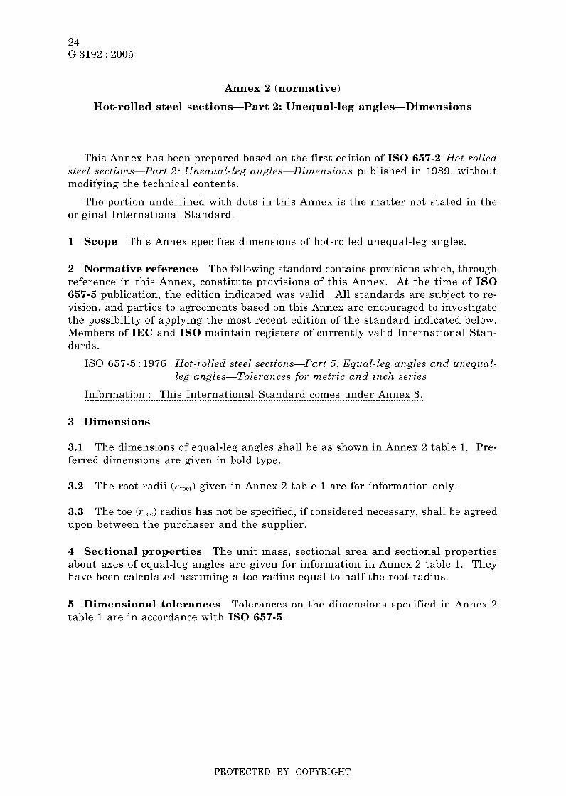
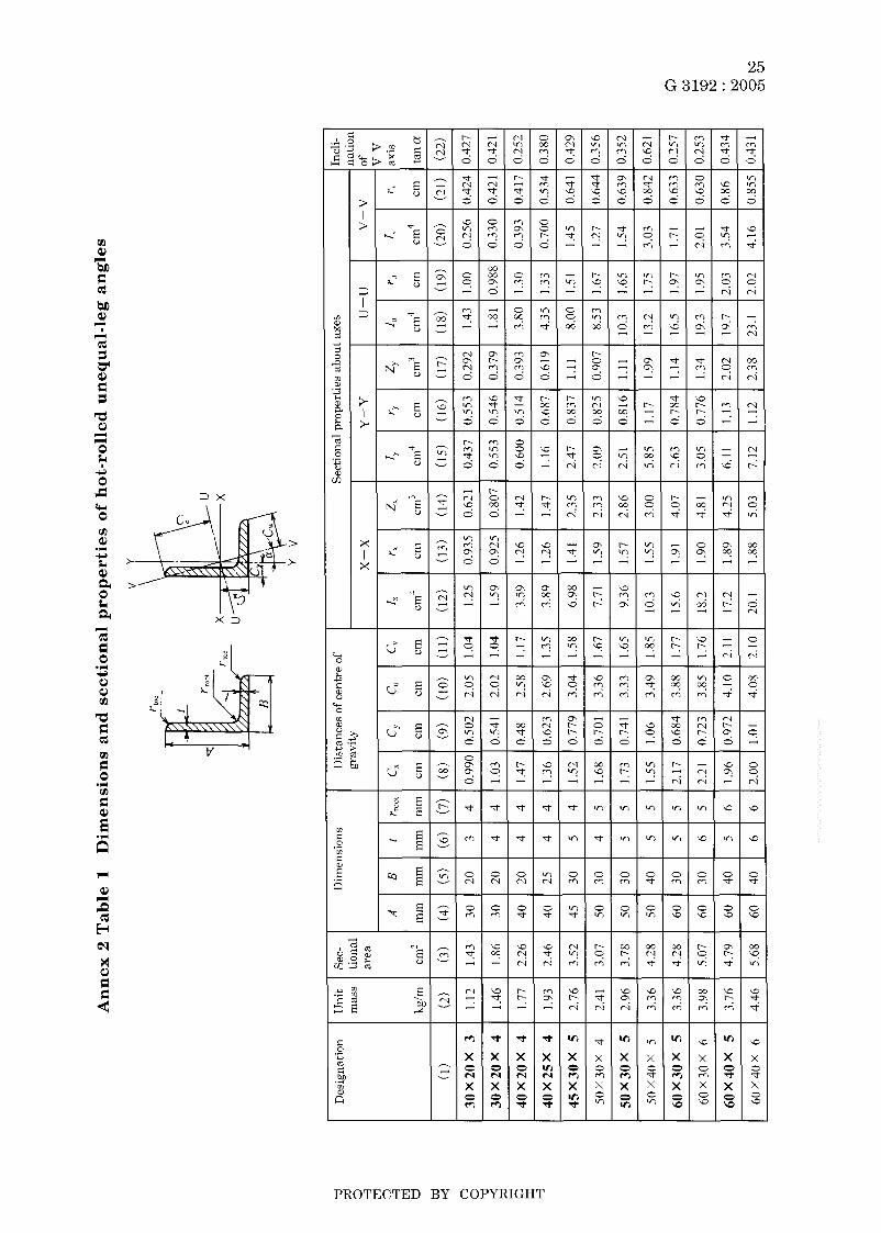
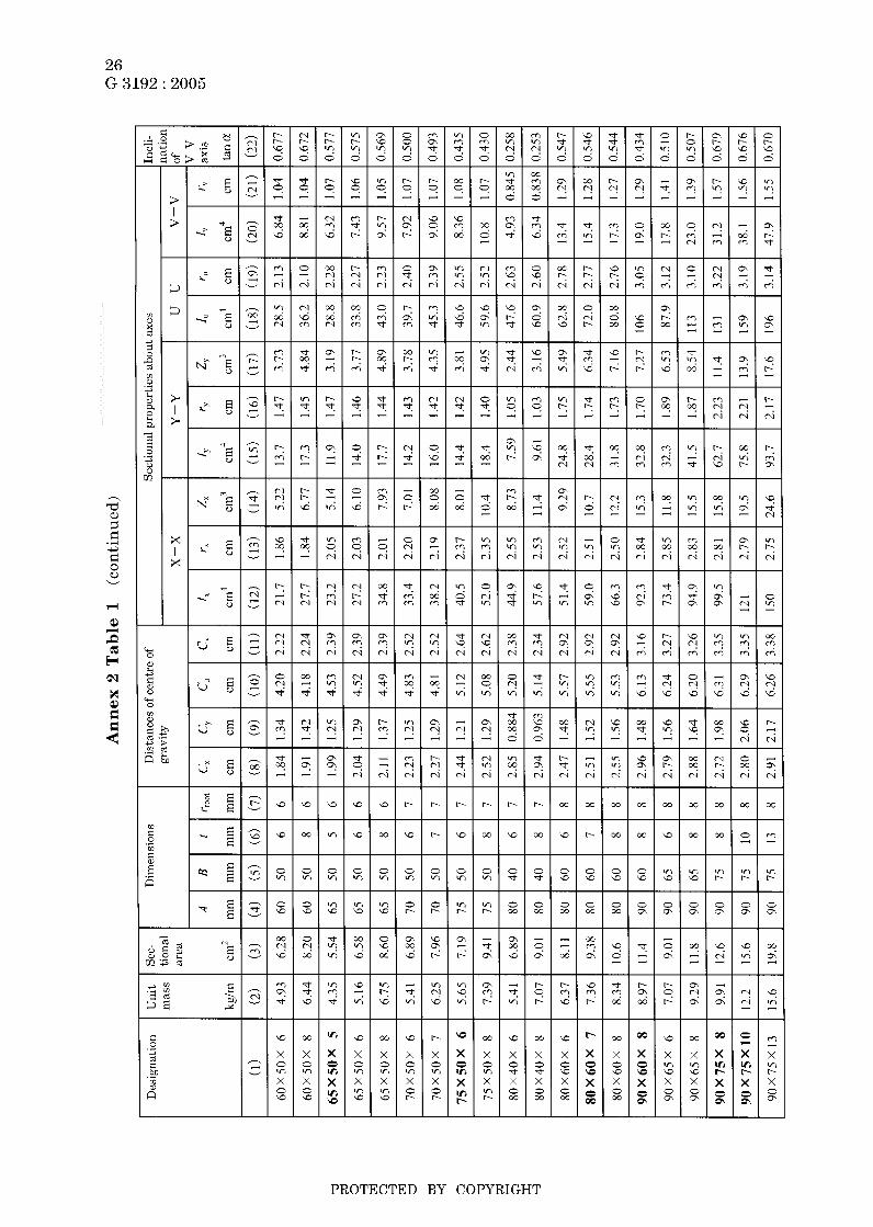
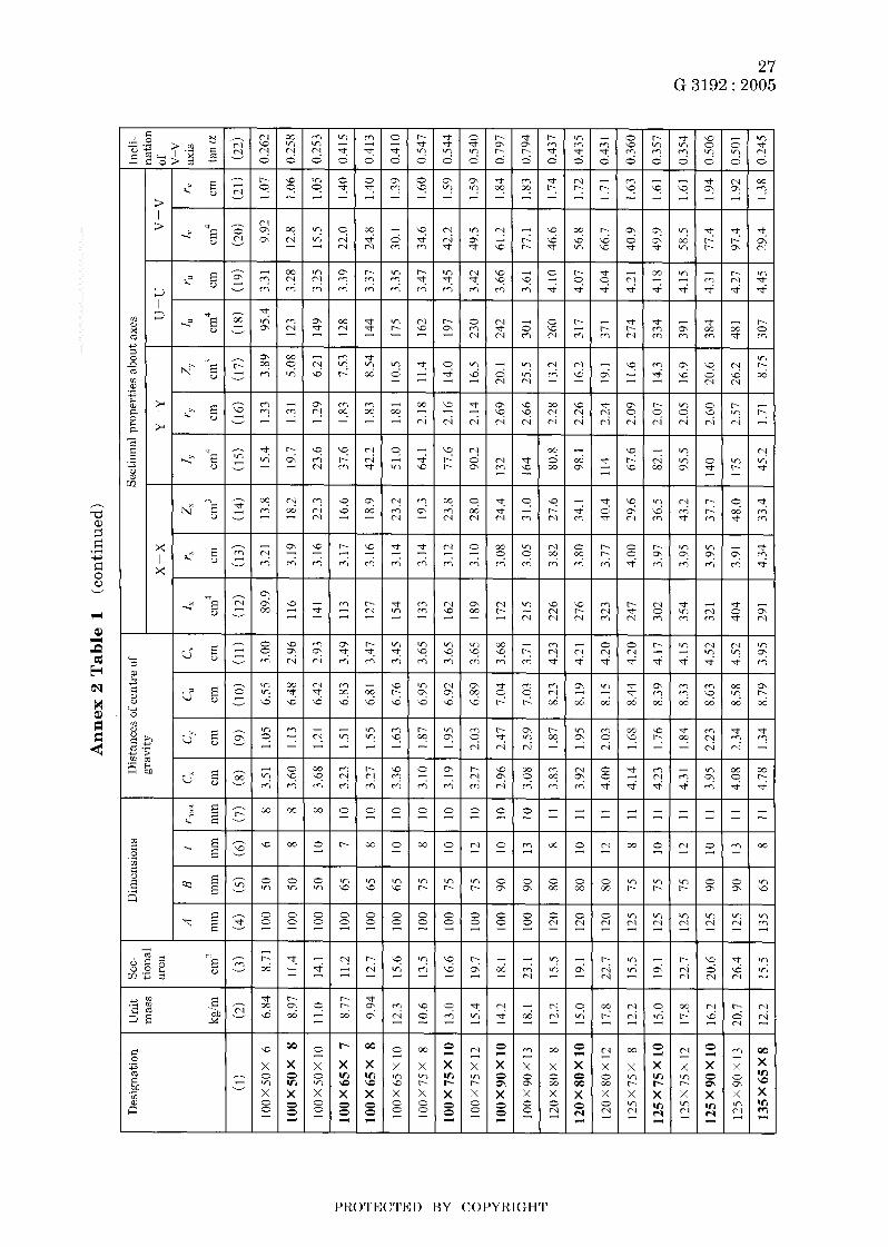
Annex 2 (normative)
Hot-rolled steel sections-Part 2: Unequal-leg angles-Dimensions
This Annex has been prepared based on the first edition of IS0 657-2 Hot-rolled steel sections-Part 2: Unequal-leg angles-Dimensions published in 19û9, without modifying the technical contents.
original International Standard. The portion underlined with dots in this Annex is the matter not stated in the
1 Scope This Annex specifies dimensions of hot-rolled unequal-leg angles.
2 Normative reference The following standard contains provisions which, through reference in this Annex, constitute provisions of this Annex. At the time of IS0 657-5 publication, the edition indicated was valid. All standards are subject to re- vision, and parties to agreements based on this Annex are encouraged to investigate the possibility of applying the most recent edition of the standard indicated below. Members of IEC and IS0 maintain registers of currently valid International Stan- dards.
IS0 657-5 : 1976 Hot-rolled steel sections-Part 5: Equal-leg angles and unequal- leg angles-Tolerances for metric and inch series
Information : This International Standard comes under Annex 3.
3 Dimensions
3.1 ferred dimensions are given in bold type.
The dimensions of equal-leg angles shall be as shown in Annex 2 table 1. Pre-
3.2 The root radii (rroot) given in Annex 2 table 1 are for information only.
3.3 upon between the purchaser and the supplier.
The toe (rloe) radius has not be specified, if considered necessary, shall be agreed
4 Sectional properties The unit mass, sectional area and sectional properties about axes of equal-leg angles are given for information in Annex 2 table 1. They have been calculated assuming a toe radius equal t o half the root radius.
5 Dimensional tolerances table 1 are in accordance with IS0 657-5.
Tolerances on the dimensions specified in Annex 2
PROTECTED BY COPYRIGHT
25 G 3192 : 2005
3 x
x 3
i
* 4’ 6
i 5
PROTECTED BY COPYRIGHT
--```,`,,```,`,`,``,`,`,````,-`-`,,`,,`,`,,`---
26 G 3192 : 2005
r..*
PROTECTED BY COPYRIGHT
--```,`,,```,`,`,``,`,`,````,-`-`,,`,,`,`,,`---
27 G 3192 : 2005
i g
4 E u 7-t
- 3 3
o
a"
.i c)
.r a 2 i
X in \c
I I
PROTECTED BY COPYRIGHT
--```,`,,```,`,`,``,`,`,````,-`-`,,`,,`,`,,`---

28 G 3192 : 2005
i
t d C N
Z I Z I 2
3
+ w r - 3 ' l e l o
W
2 m F! 9
m m i n
N i n 0 P 3 N
c o o x x x z211 x x x 0 0 0 O 0 0 N N N
PROTECTED BY COPYRIGHT

29 G 3192 : 2005
E
2 u g 3
E v
m m
a
.. u
E o -. bo
Lo
c- k O
al a c, m k O
h Y
09
+
.3
8 a k O
ci, .d
ci, cb P a 9 2
o o
a al + cd 3
3
ci, .3
v1
E
PROTECTED BY COPYRIGHT
--```,`,,```,`,`,``,`,`,````,-`-`,,`,,`,`,,`---
30 G 3192 : 2005
Annex 3 (normative)
Hot-rolled steel sections-Part 3: Equal-leg angles and unequal-leg angles-Tolerances
This Annex has been prepared based on the first edition of IS0 657-5 Hot-rolled steel sections-Part 5: Equal-leg angles and unequal-leg angles-Tolerance for met- ric und inch series published in 1976, without modifying the technical contents.
The portion underlined with dots in this Annex is the matter not stated in the original International Standard.
1 This Annex specifies the dimensional tolerances applicable to hot-rolled steel angles having either equal or unequal leg lengths in accordance with IS0 657-1 and
Information : These International Standards come under Annex 1 and Annex 2.
Scope
IS0 657-2.
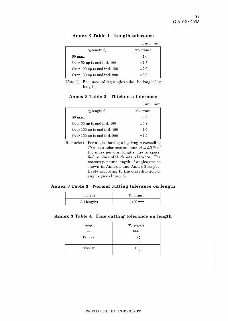
2 Leg length tolerance table 1.
Tolerances on leg length shall be as shown in Annex 3
3 Thickness tolerance table 2.
Tolerances on thickness shall be as shown in Annex 3
4 Cutting tolerances for length be as shown in Annex 3 table 3 and Annex 3 table 4 respectively.
Normal and fine tolerances for lengths shall
5 Straightness
5.1 The maximum permissible camber shall be as shown in Annex 3 table 5.
5.2 The camber shall be measured as shown in Annex 3 figure 1.
6 Out-of-square
6.1 The maximum deviation of out-of-square is in accordance with Annex 3 table 6.
6.2 figure 2.
The deviation shall be measured a t the end of leg in accordance with Annex 3
7 Tolerance on mass Where tolerance on mass per unit length is to be specified a s an overall controlling, tolerance shall be agreed upon between the purchaser and the supplier.
PROTECTED BY COPYRIGHT
--```,`,,```,`,`,``,`,`,````,-`-`,,`,,`,`,,`---
31 G 3192 : 2005
Length m
Annex 3 Table 1 Length tolerance
Unit: mm
Tolerance mm
I Leg length (l) I Tolerance I
Over 12
50 max.
Over 50 up to and incl. 100
Over 100 up to and incl. 150
Over 150 up to and incl. 200
+ 100 O
L 1.0
I 1.5
12.0
I 3.0
Note (1) For unequal-leg angles take the longer leg length.
Annex 3 Table 2 Thickness tolerance
Unit: mm I Leg length (l) I Tolerance I
50 max.
Over 50 up to and incl. 100
Over 100 up to and incl. 150
Over 150 up to and incl. 200
I 0.5
I 0.8
L 1.0
I 1.2
Remarks : For angles having a leg length exceeding 75 mm, a tolerance on mass of = 2.5 % of the mass per unit length may be speci- fied in place of thickness tolerance. The masses per unit length of angles are as shown in Annex 1 and Annex 2 respec- tively according to the classification of angles (see clause 1).
Annex 3 Table 3 Normal cutting tolerance on length
I Length I Tolerance I I All lengths I = 100 mm I
Annex 3 Table 4 Fine cutting tolerance on length
12 max. + 75 O
PROTECTED BY COPYRIGHT
--```,`,,```,`,`,``,`,`,````,-`-`,,`,,`,`,,`---

32 G 3192 : 2005
Leg length (l)
50 max.
Over 50 up to and incl. 100
Annex 3 Table 5 Camber
Maximum deviation
1.0
2.0
Leg length(l) mm
Straightness tolerance
I Over 50 up to and incl. 150 I 0.4 5% of length
I Over 150 up to and incl. 250 I 0.25 ’% of length
Length of angle < D
Annex 3 Figure 1 Measurement of camber
Annex 3 Table 6 Out-of-square
Unit: mm
I Over 100 up to and incl. 200 I 3.0 I
Devia- Devia-
I
Annex 3 Figure 2 Measurement of deviation
PROTECTED BY COPYRIGHT

33 G 3192 : 2005
Annex 4 (normative)
Hot-rolled steel sections-Part 4: Sloping flange channel sections- Dimensions and sectional properties
This Annex has been prepared based on the first edition of IS0 657-11 Hot-rolled steel sections-Part 11: Sloping flange channel sections (Metric series)-Dimensions and sectional properties published in 1980, without modifying the technical contents.
1 steel sloping flange channel sections.
Scope This Annex specifies dimensions and sectional properties of hot-rolled
2 Designation CH followed by the depth and mass per metre.
Sloping flange channel sections shall be designated by the letters
Example : CH160 x 18
3 Dimensions and sectional properties The dimensions and sectional proper- ties of sloping flange channel sections shall be as shown in Annex 4 table 1.
PROTECTED BY COPYRIGHT
--```,`,,```,`,`,``,`,`,````,-`-`,,`,,`,`,,`---

34 G 3192 : 2005
Annex 4 Table 1 Dimensions and sectional properties of hot-rolled steel sloping flange channel sections
Y
- Eent- roid
Jn i t nass
- M
<gim - (2)
iec- iona .rea
A -
cni2
(3) -
Dimensions Sectional properties about axes Designa- tion
(1)
CH SOX 8
CH100x 10
CH120x 12
CH140 X 15
CH160X 18
CHI 80 X 21
CH200 X 25
CH220 X 29
CH250 X 34
CH300 X 45
CH350 X 52
CH400 X 59
x-x Y-Y - H
inm - (4)
- B
mm - (5)
- t
nm - :7) - 5.5
5.9
6.3
6.7
7.2
7.7
8.2
8.7
9.2
0.0
0.5
1 .o -
1'('1 mm
G cm
zx c1n'
y*
cm
rv
cm
(8) (10) ( I l ) (15) (16)
1.30
1.44
1.57
1.67
1.81
1.94
2.10
2.23
2.36
2.80
2.74
2.68
- x.2:
10.3
12.5
15.0
18.2
21.3
25.2
28.7
33.9
45.2
51.8
58.9
10.5
13.1
16.0
19.2
23.2
27.2
32. I
36.6
43.2
57.5
66.0
75.0
80
1 O0
120
140
I60
1x0
200
220
250
3 O0
350
400
45
50
55
60
65
70
75
80
85
I O0
1 O0
1 O0 -
7.5
8.0
8.5
9.0
10.0
10.5
11.5
12.0
13.0
15.0
16.0
17.0 -
8.0
8.0
8.0
9.0
9.0
10.0
12.0
12.0
13.5
15.0
16.0
17.0 -
4.0
4.5
4.5
4.5
5.5
5.5
6.0
6.5
7.0
8.0
8.0
x.5 -
1.43
1.51
1 .ho
1.68
1 .x1
1.90
2.02
2.11
2.20
2.60
2.48
2.38 -
102
200
350
570
900
1320
1930
2 640
4 O00
7 800
i 1 900
17 200 -
25.6
40.0
58.4
81.4
1 I3
147
193
240
320
520
678
858
3.12
3.91
4.68
5.45
6.22
6.98
7.75
8.50
9.63
11.6
13.4
15.2
18.0
27.2
39.5
55.3
79.0
1 O5
142
183
240
452
496
541
5.85
7.77
IO. 1
12.8
16.8
20.6
26.0
31.0
38.2
61.1
66.3
71.0
Note (1) The fillet and toe radii (R and T ) are shown only for information and for calculating if the sectional properties.
PROTECTED BY COPYRIGHT

35 G 3192 : 2005
Annex 5 (normative)
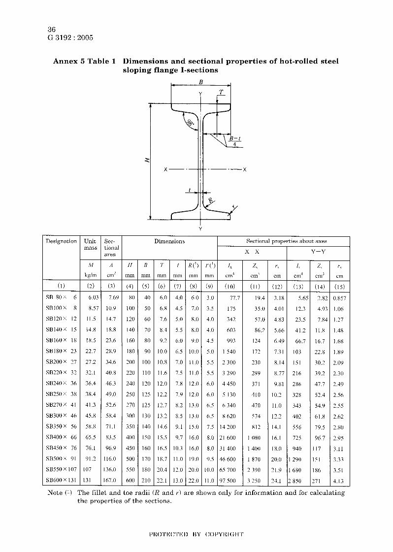
Hot-rolled steel sections-Part 5: Sloping flange I-sections- Dimensions and sectional properties
This Annex has been prepared based on the first edition of IS0 657-15 Hot-rolled steel sections-Part 15: Sloping flange beam sections (Metric series)-Dimensions and sectional properties published in 1980, without modifying the technical contents.
1 steel sloping flange I-sections.
Scope This Annex specifies the dimensions and sectional properties of hot-rolled
2 Designations followed by the depth and mass per metre.
Sloping flange I-sections shall be designated by the letters SB
Example : SB160 x 18
3 Dimensions and sectional properties The dimensions and sectional proper- ties of sloping flange I-sections shall be as shown in Annex 5 table 1.
PROTECTED BY COPYRIGHT
--```,`,,```,`,`,``,`,`,````,-`-`,,`,,`,`,,`---
36 G 3192 : 2005
Annex 5 Table 1 Dimensions and sectional properties of hot-rolled steel sloping flange I-sections
I- B
Y - Unit mass
- M
kgim
- Sec- tional area
A -
cm2
Dimensions Sectional properties about axes Designation
(1)
SB 80X 6
SB100x 8
Sß120X 12
SB140X 15
SB160x 18
SB180X 23
SB200x 27
Sß220X 32
SB240X 36
SB250X 3X
SB270x 41
SB300X 46
SB350x 56
SB400x 66
SB450x 76
SB500X 91
SB550 X 107
SB600x 131
x-x Y-Y
H
mm
B
itim
T
mm
t mm
2,
cm' r x
crn
r,
cm - (15) -
0.857
I .O6
1.27
1.48
1 .68
1 .89
2.09
2.30
2.49
2.56
2.55
2.62
2.80
2.95
3.11
3.33
3.51
4.13
(2) - 6.03
8.57
11.5
14.8
1 8.5
22.7
27.2
32.1
36.4
38.4
41.3
45.8
58.8
65.5
76. I
91.2
107
131
(3) (4) (5) (7) (10) (12)
7.69
10.9
14.7
18.8
23.6
28.9
34.6
40.8
46.3
49.0
52.6
58.4
71.1
83.5
96.9
16.0
36.0
67.0
8 o 1 00
120
I40
160
180
200
220
240
250
270
300
350
400
450
5 00
550
600
40
50
60
70
80
90
1 00
110
120
125
125
130
140
150
160
170
180
210
6.0
6.8
7.6
8.4
9.2
10.0
10.8
11.6
12.0
12.2
12.7
13.2
14.6
15.5
16.5
18.7
20.4
22.1
4.0
4.5
5.0
5.5
6.0
6.5
7.0
7.5
7.8
7.9
8.2
8.5
9.1
9.7
10.3
11.0
12.0
13.0
6.0
7.0
8.0
8.0
9.0
10.0
11.0
11.0
12.0
12.0
13.0
13.0
15.0
16.0
16.0
19.0
20.0
22.0
3.0
3.5
4.0
4.0
4.5
5.0
5.5
5.5
6.0
6.0
6.5
6.5
7.5
8.0
8.0
9.5
10.0
11.0 -
19.4
35.0
57.0
86.2
124
172
230
299
371
410
470
574
812
1 O80
1400
I870
2 390
3 250
3.18
4.01
4.83
5.66
6.49
7.31
8.14
8.77
9.81
10.2
11.0
12.2
14.1
16.1
18.0
20.0
21.9
24.1
5.65
12.3
23.5
41.2
66.7
I03
151
216
286
328
343
402
556
725
940
290
680
850
2.82
4.93
7.84
11.8
16.7
22.8
30.2
39.2
47.7
52.4
54.9
61.8
79.5
96.7
117
51
86
!71
77.7
175
342
603
993
I540
2 300
3 290
4 450
5 130
h 340
8 620
I 4 200
? I 600
3 1 400
16 600
i5 700
97 500
Note (1) The fillet and toe radii (R and 1-1 are shown only for information and for calculating the properties of the sections.
PROTECTED BY COPYRIGHT
37 G 3192 : 2005
Annex 6 (normative)
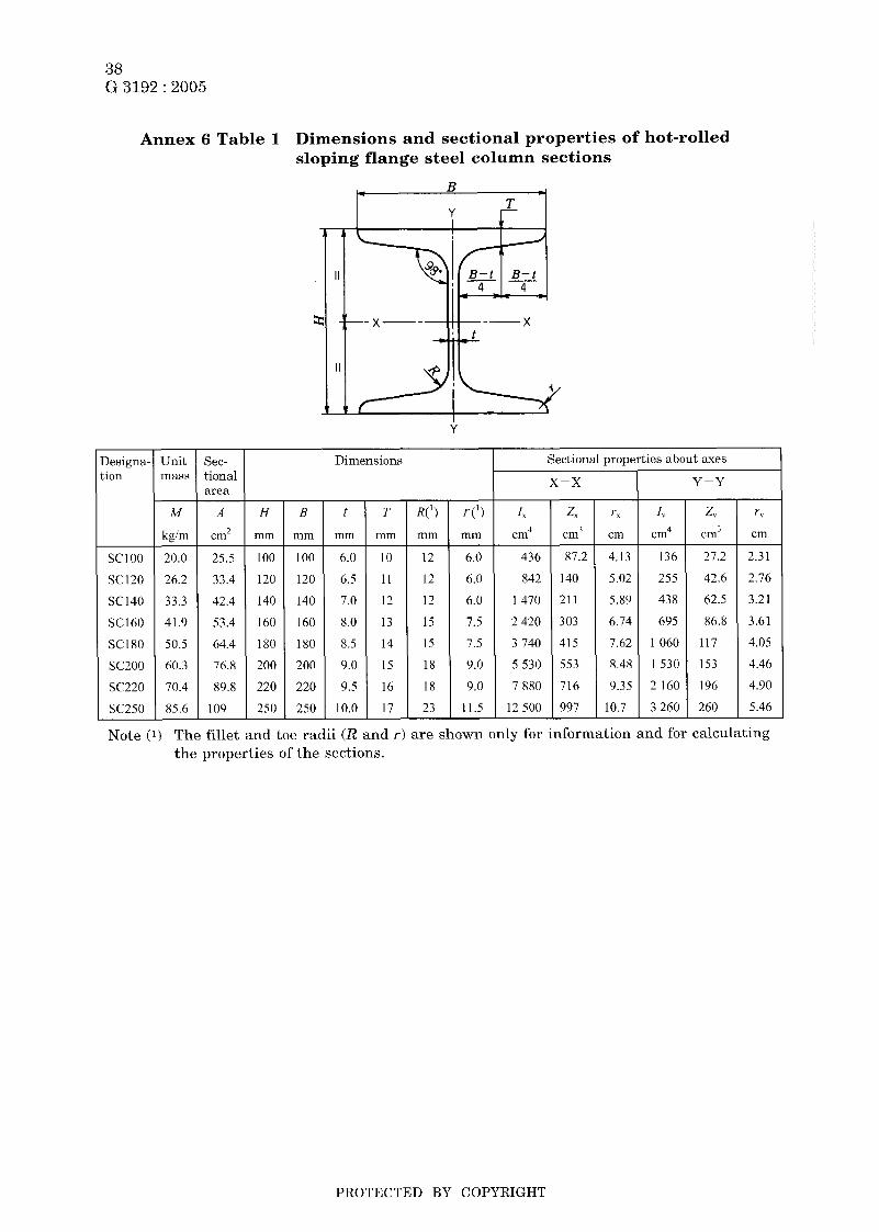
Hot-rolled steel sections-Part 6: Sloping flange column sections- Dimensions and sectional properties
This Annex has been prepared based on the first edition of IS0 657-16 Hot-rolled steel sections-Part 16: Sloping f lange column sections (metric series)-Dimensions and sectional properties published in 1980, without modifying the technical contents.
1 sloping flange steel column sections.
Scope This Annex specifies the dimensions and sectional properties of hot-rolled
2 Designations ters SC followed by the depth of the column.
Sloping flange column sections shall be designated by the let-
Example : SC100
3 Dimensions and sectional properties The dimensions and sectional proper- ties of sloping flange column sections shall be as shown in Annex 6 table 1.
PROTECTED BY COPYRIGHT
--```,`,,```,`,`,``,`,`,````,-`-`,,`,,`,`,,`---
38 G 3192 : 2005
Annex 6 Table 1 Dimensions and sectional properties of hot-rolled sloping flange steel column sections
B
Y t- T
Y - Unit mass
Sectional properties about axes lesigna- .ion
Dimensions Sec- tional area x-x Y-Y
- r(9 mm
6.0
6.0
6.0
7.5
7.5
9.0
9.0
11.5
-
-
- ''X
cm
4.13
5.02
5.8'1
6.74
7.62
8.48
9.35
-
10.7 -
- T
mm
- z,
cm3
87.2 -
140
21 1
303
41 5
553
716
997 -
r v
cm
2.3 i
2.76
3.2 i
3.61
4.05
4.46
4.90
5.46
-
M
kgirn
20.0
26.2
33.3
41 .Y
50.5
60.3
70.4
85.6
-
A
ern' H
rnrn
B
mm
1 O0
120
140
160
180
200
220
250
-
t mm
I> c1n4
136
255
438
695
1060
I 5 3 0
2 160
3 260
Z,
cm3
27.2
42.6
62.5
86.8
117
153
196
260
SCI O0
sc120
SC140 SC160
SC180 sc200
sc220
sc250
25.5
33.4
42.4
53.4
64.4
76.8
89.8
i 09
1 O0
120
140
160
180
200
220
250
6.0
6.5
7.0
8.0
8.5
9.0
9.5
10.0 -
10
I I
12
13
14
15
16
17 -
12
12
12
15
15
18
18
23 -
436
842
I470
2 420
3 740
5 530
7 880
12 500
Note (1) The fillet and toe radii (R and r ) are shown only for information and for calculating the properties of the sections.
PROTECTED BY COPYRIGHT
--```,`,,```,`,`,``,`,`,````,-`-`,,`,,`,`,,`---

39 G 3192 : 2005
Annex 7 (normative)
Hot-rolled steel sections-Part 7: L-sections for shipbuilding- Dimensions, sectional properties and tolerances
This Annex has been prepared based on the first edition of IS0 657-18 Hot-roZled steel sections-Part 18: L sections for shipbuilding (metric series)-Dimensions, sec- tional properties und tolerances published in 1980, without modifying the technical contents.
1 tolerances for hot-rolled steel L-sections for shipbuilding.
Scope This Annex specifies the dimensions, sectional properties and dimensional
2 Designations Hot-rolled steel L-sections for shipbuilding shall be designated by the letter L followed by the height of the web ( H ) , the width of the flange (B) , the thickness of the web ( t ) and the thickness of the flange (5") .
Example : L250 x 90 x 9 x 13
3 Dimensions and sectional properties The dimensions and sectional proper- ties of L-sections for shipbuilding shall be as shown in Annex 7 table 1.
PROTECTED BY COPYRIGHT
--```,`,,```,`,`,``,`,`,````,-`-`,,`,,`,`,,`---

40 G 3192 : 2005
Annex 7 Table 1 Dimensions and sectional properties of L-sections for shipbuilding
Designation
L200X 9 0 X 9 X I 2
L225X 9 0 x 9 X12
L250X 9 0 X 9 X I 3
L250X 90X10 .5X15
L250X 90X11.5X16
L27S X 100 X 10.5 X 14
L 3 0 0 x 100 x 10.5 x IS
L300X 100X 11.5 X 16
L325 x 120 x 10.5 x 14
L325 x 120 x 11.5 x 15
L35OX120X 10.5X 16
L 3 5 0 x 1 2 0 x 1 1 . 5 ~ 18
L375 X 120X 10.5 X 18
L375X120X11.5X20
L 4 0 0 x 1 2 0 x 1 1 . 5 ~ 2 3
L425 x 120 X 11.5 x 23
L450 x 120 x 11.5 x 2 5
L475 X 120 X 11.5 X 28
L47SX 120x 1 2 3 x 3 0
L500 x 120 x 12.5 x 33
L500X120X13.5X35
Unit mass
M
kgím
22.0
23.8
26.2
30.3
32.7
32.8
35.6
38.5
39.3
42.6
43. I
47.4
46.9
51.4
56.2
59.3
62.4
67.2
72.4
77.4
82.8
Sec- tional a rea
A
cm'
28.1
30.3
33.4
38.5
41.7
41.8
45.3
49.0
50.1
54.3
54.9
60.4
59.7
65.4
71.6
75.5
79.5
85.6
92.2
98.6
1 05
H
mm
200
225
250
250
250
275
300
3 00
325
325
350
350
3 75
3 75
400
425
450
475
475
500
500
B
mm
90
90
90
90
90
1 00
1 00
1 o0
120
120
120
120
I20
120
120
120
120
120
120
120
120
Dimensions
- t
mm
Y
9
9
10.5
11.5
10.5
10.5
11.5
10.5
11.5
10.5
11.5
10.5
11.5
11.5
11.5
11.5
11.5
12.5
12.5
13.5
-
T
m m
12
12
13
15
16
14
15
Ih
14
15
16
1x
18
20
23
24
25
28
30
33
35
- R
mm
15
15
15
15
15
15
15
15
20
2 o 20
20
20
20
20
20
20
20
20
20
20
r
mm
7.5
7.5
7.5
7.5
7.5
7.5
7.5
7.5
10
10
10
10
10
10
1 o 10
10
10
10
10
10
Cent- roid
CX
cm
6.63
7.71
8.64
8.76
8.90
9.72
10.6
10.7
11.3
11.4
12.0
12.0
12.7
12.7
13.3
14.2
15.1
15.7
15.9
16.5
16.6
Moment of inertia
1, cm4
1 160
1610
2 190
2 510
2 710
3 330
4 290
4 630
5 600
6 060
7 110
7 780
8 850
9 650
11 900
14 200
16 800
20 100
21 600
25 500
27 100
PROTECTED BY COPYRIGHT
--```,`,,```,`,`,``,`,`,````,-`-`,,`,,`,`,,`---
41 G 3192 : 2005
4 Tolerances
4.1 ( H ) and width of flange ( B ) shall be as shown in Annex 7 table 2.
Height of web ( H ) and width of flange (B) The tolerances on height of web
Annex 7 Table 2 Tolerances of height of web ( H ) and width of flange (B)
Unit: mm
I Height of web (Hl I Tolerances on (Hl and (B) I I 200 max. I * 3 I I Over 200 I + 4 I
4.2 and the minus side tolerance shall be 0.4 mm.
Web thickness ( t ) The plus side tolerance on web thickness ( t ) shall be 1.6 mm
4.3 in Annex 7 table 3 .
Flange thickness (T) The tolerance on flange thickness (2') shall be as shown
Annex 7 Table 3 Tolerance on flange thickness (T) Unit: mm
I Flange thickness (T) I Tolerance on (2') I 20 max. - 2.0 I ~ 0.4 I Over 20 up to and incl. 30 ~ 2.0
~ 0.5 I Over 30 up to and incl. 35 2.5
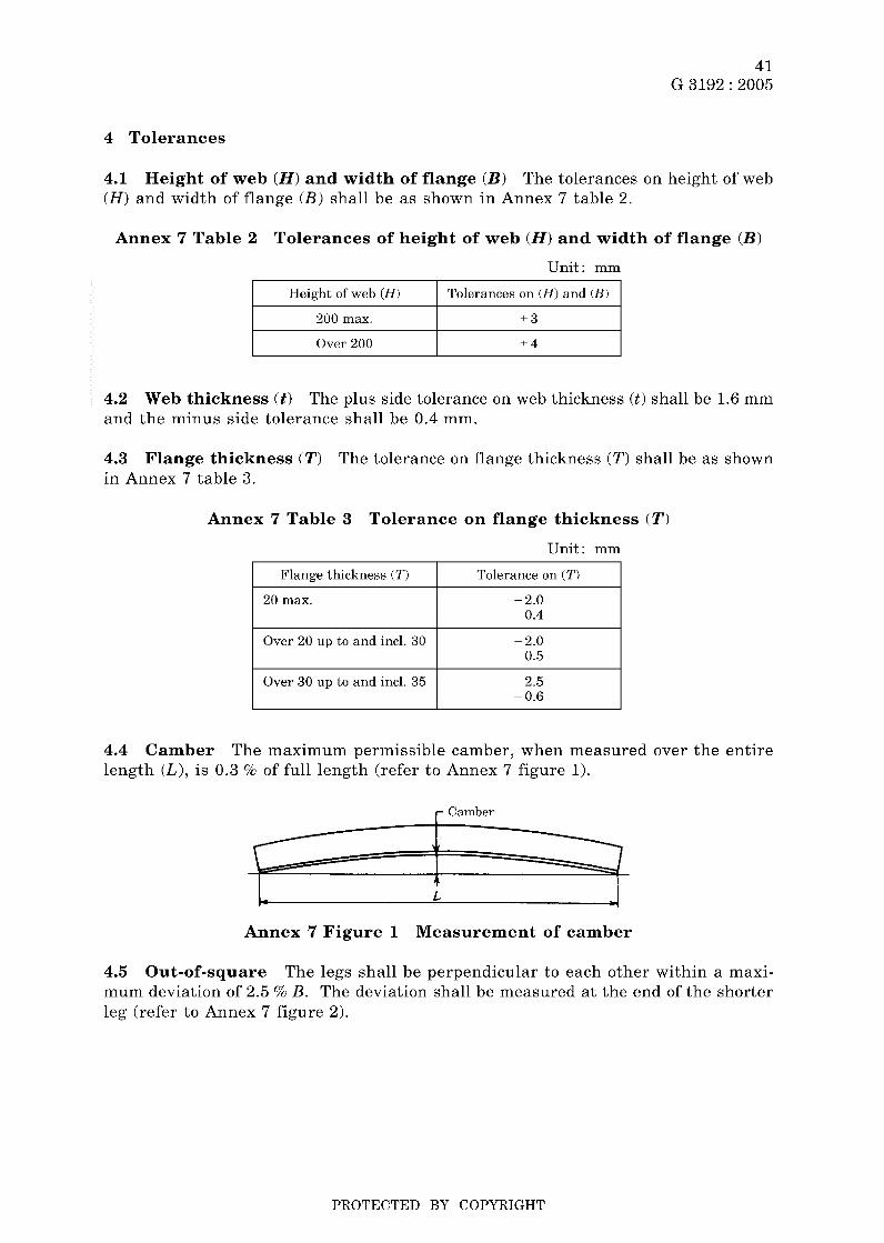
~ 0.6 I 4.4 length (L ) , is 0.3 % of full length (refer to Annex 7 figure 1).
Camber The maximum permissible camber, when measured over the entire
r Camber
Annex 7 Figure 1 Measurement of camber
4.5 Out-of-square The legs shall be perpendicular to each other within a maxi- mum deviation of 2.5 % B. The deviation shall be measured at the end of the shorter leg (refer to Annex 7 figure 2).
PROTECTED BY COPYRIGHT
--```,`,,```,`,`,``,`,`,````,-`-`,,`,,`,`,,`---

42 G 3192 : 2005
Deviation Deviation
, ! I I
Q I : I f
i 'I [ I f \ ,
Annex 7 Figure 2 Measurement of out-of-square
4.6 Flatness The tolerance on flatness of the web shall be the subject of agree- ment between the purchaser and the supplier. The measurement of deviation from flatness shall be as shown in Annex 7 figure 3. e,
Deviation
Annex 7 Figure 3 Measurement of deviation in flatness of web
4.7 Length The tolerance on length shall be between +ioo mm. The L-sections for shipbuilding may be supplied to tighter length tolerances according to agreement be- tween the purchaser and the supplier.
PROTECTED BY COPYRIGHT
--```,`,,```,`,`,``,`,`,````,-`-`,,`,,`,`,,`---

43 G 3192 : 2005
Annex 8 (normative)
Hot-rolled steel sections-Part 8: Bulb flats-Dimensions, sectional properties and tolerances
This Annex has been prepared based on the first edition of IS0 657-19 Hot-rolled steel sections-Part 19: Bulb f lats (metric series)-Dimensions, sectional properties und tolerances published in 1980, without modifying the technical contents.
1 steel bulb flats and their dimensional tolerances.
Scope This Annex specifies dimensions and sectional properties of hot-rolled
2 Designation thickness ( t ) .
Hot-rolled steel bulb flats shall be designated by the width ( b ) and
Example : 200 x 10
3 Dimensions and sectional properties The dimensions and sectional proper- ties of bulb flats shall be as shown in Annex 8 table 1.
PROTECTED BY COPYRIGHT
--```,`,,```,`,`,``,`,`,````,-`-`,,`,,`,`,,`---

44 G 3192 : 2005
Annex 8 Table 1 Dimensions and sectional properties of bulb flats
lesignation
80X 6
80X 7
1 0 0 x 7
1 0 o x 8
1 2 0 x 7
1 2 0 x 8
140X 7
140X 8
160X 7
160X 8
160X 9
180X 8
180X 9
1 8 0 x 1 0
2 0 0 x 9
2 0 0 x 10
2 0 0 x 11.5
220 x 10
220X 11.5
240 X 1 0
240X 11
240 X 12
260X 10
260X I I
260 x 12
280X I I
280 x 12
300X 11
Unit mass
M
k d m
4.87
5.50
6.86
7.65
8.25
9.19
9.74
10.8
11.4
12.7
14.0
14.8
16.2
17.6
I X.5
20.1
22.5
22.8
25.4
25.4
27.4
29.3
28.3
30.3
32.4
33.5
35.7
36.7
iec- ional irea
A
cmz
6.20
7.00
8.74
9.74
10.5
11.7
12.4
13.8
14.6
16.2
17.8
18.9
20.7
22.5
23.6
25.6
28.6
29.0
32.3
32.4
34.9
37.3
36.1
38.7
41.3
42.6
45.5
46.7
b
mm
80
80
1 00
1 00
120
120
140
140
160
160
160
180
180
180
200
200
200
220
220
240
240
240
260
260
260
280
280
300
Dimensions
t
mm
6
7
7
8
7
8
7
8
7
8
9
8
9
1 o 9
10
11.5
10
11.5
10
11
12
10
11
12
11
12
11
- c
inm
14
14
15.5
15.5
17
17
19
19
22
22
22
25
25
25
28
28
28
31
31
34
34
34
37
37
37
40
40
43
-
-
VI
mm
4
4
4.5
4.5
5
5
5.5
5.5
6
6
6
7
7
7
8
8
8
9
9
10
10
10
11
11
11
12
12
13
urface rea
m2/m
0.192
0.194
0.236
0.238
0.278
0.280
0.320
0.322
0.365
0.367
0.369
0.41 1
0.413
0.415
0.457
0.459
0.462
0.503
0.506
0.547
0.549
0.551
0.593
0.593
0.595
0.637
0.639
0.681
- Zent- Poid
c: cm
4.78
4.69
5.87
5.78
7.07
6.96
8.3 I
8.18
9.66
9.49
9.36
-
10.9
10.7
10.6
12.1
11.9
11.7
13.4
13.1
14.7
14.6
14.4
16.2
16.0
15.8
17.4
17.2
18.9 -
Sectional properties
39.0
43.3
85.3
94.3
148
164
24 I
26X
373
411
488
609
663
717
84 1
1020
1130
1400
1550
1 860
2 000
2 130
2 470
2 610
2 770
3 330
3 550
4 190
2, cm3
8.15
9.24
14.5
16.3
21.0
23.6
29.0
32.5
38.6
43.3
47.9
55.9
61.8
67.8
77.7
85.0
96.2
105
118
126
137
148
153
162
175
191
206
222
PROTECTED BY COPYRIGHT

45 G 3192 : 2005
120 max.
Annex 8 Table 1 (concluded)
Over 6.0 up to * 1.5 + 0.7 and incl. 8.0 0.3
Designation
300 X 12
300X 13
320 X 12
320 X 13
34OX 12
340 X 14
37OX 13
370 X 15
400 X 14
400 X 16
430 X 15
430X 17
Over 120 up to andincl. 180
Unit mass
Over 7.0 up to L 2.0 i1 and incl. 10.0 ~ 0.3
M
kgim
39.0
41.5
42.5
45.0
46.1
51.5
54.6
60.5
63.9
70.2
73.9
80.6
Over 180 up to and incl. 300
Sec- tional area
Over 9.0 up to * 3.0 + 1 and incl. 13.0 0.4
A
tin' 49.7
52.8
54.2
57.4
58.8
65.5
69.6
77.0
81.4
89.4
94. I
103
Over 300 up to and incl. 430
b
mm
3 O0
300
320
320
340
340
370
370
400
400
430
430
Over 12.0 up to * 4.0 + 1.2 and incl. 17.0 ~ 0.4
Dimensions
t
mm
12
13
12
13
12
14
13
15
14
16
15
17
(.’
min
43
43
46
46
49
49
53.5
53.5
58
58
62.5
62.5
-
YI
mm
13
13
14
14
15
15
16.5
16.5
18
18
19.5
19.5
iurface rea
ni2iin
0.683
0.685
0.728
0.730
0.772
0.776
0.840
0.844
0.4, ox 0.912
0.976
0.980
Cent- roid
cx cm
18.7
I 8.5
20.1
19.Y
21.5
21.1
23.5
23.0
25.5
25.0
27.4
26.9
Sectional properties
l x cm4
4 460
4 720
5 530
5 850
6 760
7 540
9 470
10 400
12 900
14 200
17 300
18 900
Z Y
cin’
239
256
274
294
313
357
402
455
507
568
628
700
4 Tolerances
4.1 Width and thickness as shown in Annex 8 table 2.
The tolerances on width ( b ) and thickness ( t ) shall be
Annex 8 Table 2 Tolerances on width and thickness
Unit: mm
I Width ( h ) I Thickness ( t ) I Tolerance on width ( h ) I Tolerance on thickness ( t ) I
4.2 in Annex 8 table 3.
Radius at corner The radius ( r2 ) at corners shall be within the limits as shown
PROTECTED BY COPYRIGHT
--```,`,,```,`,`,``,`,`,````,-`-`,,`,,`,`,,`---

46 G 3192 : 2005
Over 6 up to and incl. 9
Over 9 up to and incl. 13
Annex 8 Table 3 Radius at corner
Unit: mm
2.0 max.
3.0 max.
I Thickness ( t ) I Radius ( ~ - 2 ) I I 6max. I i .5max. I
I Over 13 up to and incl. 17 I 4.0 max. I
4.3 length is 0.35 % of full length.
Camber The maximum permissible camber when measured over the entire
4.4 The plus side cutting tolerance on length shall be 100 mm and the minus side cutting tolerance shall be O mm. The bulb flats may be supplied to tighter length tolerances according to agreement between the purchaser and the supplier.
Length
4.5 Where the tolerance on mass per unit length is to be specified as the rolling tolerance in place of thickness tolerance, it shall be specified by agreement between the purchaser and the supplier.
Mass
PROTECTED BY COPYRIGHT

47 G 3192 : 2005
Annex 9 (normative)
Hot-rolled steel sections-Part 9: T-sections with equal depth and flange width-Dimensions
This Annex has been prepared based on the first edition of IS0 657-21 Hot-roZZed steel sections-Part 21: T-sections with equal depth and flange width-Dimensions published in 1983, without modifying the technical contents.
1 depth and flange width.
Scope This Annex specifies the dimensions of hot-rolled T-sections with equal
2 Dimensions The dimensions of T-sections shall be as shown in Annex 9 table 1.
3 Sectional properties of T-sections are a s shown for information in Annex 9 table 1.
The unit mass, sectional area and sectional properties
k Y B
Slope 2
X-
PROTECTED BY COPYRIGHT

48 G 3192 : 2005
Annex 9 Table 1 Dimensions and sectional properties of hot-rolled steel T-sections with equal depth and flange width
- ?ec- .ional irea
Cm2
- Jnit nass
ig/m - (3) - 0.88
1.29
1.77
2.33
2.96
3.67
4.44
6.23
8.32
9.08
0.7
3.4
6.4
i 6.4
11.3 -
Designa- tion
Dimensions Sectional properties about axes >ocation if centre if gravit3
ex
cm
x-x Y-Y - R3 mm
: 1 o) _.
- I
1
1
I
1
1.5
I .5
2
2
2.0
2
2.5
3
3
4 -
- 4
cm4
- A
mm - (4) - 20
25
30
35
40
45
50
60
70
75
XO
90
1 00
120
140 -
- B
nm - (5) - 20
25
30
35
4 o 45
50
60
70
75
80
90
1 00
120
140 -
- T
mm
(6)
3
3.5
4
4.5
5
5.5
6
7
8
8
9
10
11
13
15
-
-
-
- t
mm - (7) - 3
3.5
4
4.5
5
5.5
6
7
8
8
9
10
11
13
15 -
- RI
mm
(8) -
- 3
3.5
4
4.5
5
5.5
6
7
8
8
9
10
11
13
15 -
- R? mm
(9) - - 1.5
2
2
2.5
2.5
3
3
3.5
4
4.5
4.5
5
5.5
6.5
7.5 -
(11)
r 20 x 20
r 2 5 x 25
T 3 0 x 30
r 3 5 x 35
T 40X 40
T 45X 45
T 50X 50
T 60X 60
T 70X 70
T 75X 75
T 80X 80
T 9 0 x 90
TI00 X 10C
T120x 12C
T140X 14C
1.12
I .64
2.26
2.97
3.77
4.67
5.66
7.94
10.6
11.6
13.6
17.1
20.9
29.6
39.9 -
0.58
0.73
0.85
0.99
1.12
1.26
1.39
1.66
1.94
2.14
2.22
2.48
2.74
3.28
3.80
0.38
0.87
1.72
3.10
5.28
8.13
12.1
23.8
44.5
60.5
73.7
I i9
I79
166
i60 -
0.27
0.49
0.80
I .23
1.84
2.51
3.36
5.48
8.79
11.3
12.8
18.2
24.6
42.0
64.7 -
0.58
0.73
0.87
1 .O4
1.18
1.32
1.46
1.73
2.05
2.29
2.33
2.64
2.92
3.5 I
4.07 -
0.20
0.43
0.87
1.57
2.58
4.0 I
6.06
12.2
22.1
28.1
37.0
58.5
88.3
178
330
0.20
0.34
0.58
0.90
1.29
i .78
2.42
4.07
6.32
7.49
9.25
13.0
17.7
29.7
47.2
0.42
0.5 1
0.62
0.73
0.83
0.93
1 .o3
1.24
I .44
1.56
1.65
1.85
2.05
2.45
2.88
PROTECTED BY COPYRIGHT
--```,`,,```,`,`,``,`,`,````,-`-`,,`,,`,`,,`---

49 G 3192 : 2005
El FI .3
h
w Y
g .i c, a * al a -i
i o u -i
F1
al c, , O
a i .i
c,
a"
c,
Q, r
u
3
a, 8 4 d
PROTECTED BY COPYRIGHT
--```,`,,```,`,`,``,`,`,````,-`-`,,`,,`,`,,`---

50 G 3192 : 2005
-i c,
.i cd * 2
O o .i FI
a> c, ici O
cd 3 -i
c,
a"
.i 5
5 G h .i
i
2 z 2 0 ai a m
5 G h .i
i
2 z 2 0 ai a m
M
m .i
.i c, u
PROTECTED BY COPYRIGHT
--```,`,,```,`,`,``,`,`,````,-`-`,,`,,`,`,,`---

51 G 3192 : 2005
T II) .3
h 3
g I k O z 5
o al a
M
al
r-
x u3 FD O E
PROTECTED BY COPYRIGHT
--```,`,,```,`,`,``,`,`,````,-`-`,,`,,`,`,,`---

52. G 3192 : 2005
E fi
W
2
E
m W O
OT)
2 m W O E
Q,
2
E
m W O
H x m W O E
.. rn B
e O 4 d
rn cd a, * u .rl a c .d
a,
cd c,
a, k O e cd a,
s
5
m c .rl
3 cd
R e
d o
.rl c, cd u 5 rn rn cb o
CH O
4
: E
i)
3 O
e 3
M
rn
.ri
rn O e x m
4
E
l+
rn 3 i 2
rn c,
2 o o o
42 c
i
.r(
G
a, c,
G .r(
M u 2 z n
I
.ri +
.. E H
rn 2
3;
cd a
4 cd
.rl cri cd
a, 42
H
rn a,
a
E G
5
; .. n z
I
O
PROTECTED BY COPYRIGHT
--```,`,,```,`,`,``,`,`,````,-`-`,,`,,`,`,,`---

Errata for JIS (English edition) are printed in Standardization Journal, published monthly by the Japanese Standards Association, and also provided to subscribers of JIS (English edition) in A4oritIil? Information.
Errata will be provided upon request, please contact: Standardization Promotion Department, Japanese Standards Association 4- 1-24, Akasaka, Minato-ku, Tokyo, 107-8440 JAPAN TEL. 03-3583-8002 FAX. 03-3583-0462
PROTECTED BY COPYRIGHT
--```,`,,```,`,`,``,`,`,````,-`-`,,`,,`,`,,`---