The future linear collider Rob Appleby ASTeC Daresbury Laboratory.
Insertion Devices
Jim ClarkeASTeC
Daresbury Laboratory
CERN Accelerator School, 16 to 28 September 2007, Daresbury Laboratory
2
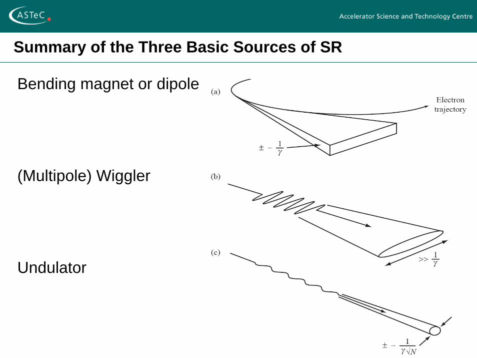
Summary of the Three Basic Sources of SR
Bending magnet or dipole
(Multipole) Wiggler
Undulator
3
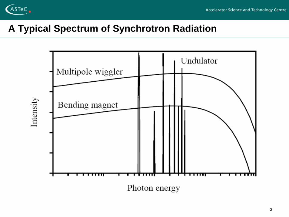
A Typical Spectrum of Synchrotron Radiation
4
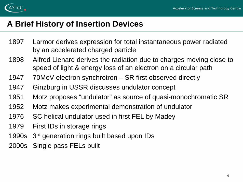
A Brief History of Insertion Devices
1897 Larmor derives expression for total instantaneous power radiatedby an accelerated charged particle
1898 Alfred Lienard derives the radiation due to charges moving close to speed of light & energy loss of an electron on a circular path
1947 70MeV electron synchrotron – SR first observed directly1947 Ginzburg in USSR discusses undulator concept1951 Motz proposes “undulator” as source of quasi-monochromatic SR1952 Motz makes experimental demonstration of undulator1976 SC helical undulator used in first FEL by Madey1979 First IDs in storage rings1990s 3rd generation rings built based upon IDs2000s Single pass FELs built
5
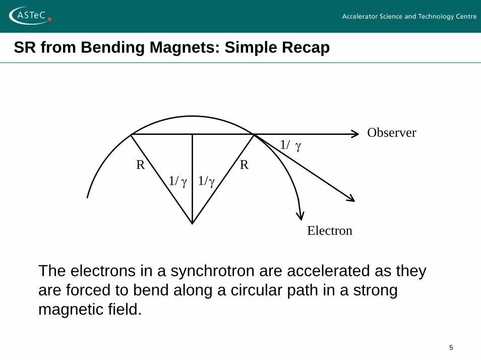
SR from Bending Magnets: Simple Recap
R1/ γ
1/ γR
1/γ
Observer
Electron
The electrons in a synchrotron are accelerated as they are forced to bend along a circular path in a strong magnetic field.
6
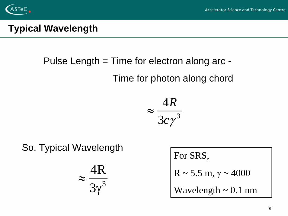
Typical Wavelength
Pulse Length = Time for electron along arc -
Time for photon along chord
334γcR
≈
So, Typical Wavelength
33R4γ
≈
For SRS,
R ~ 5.5 m, γ ~ 4000
Wavelength ~ 0.1 nm
7
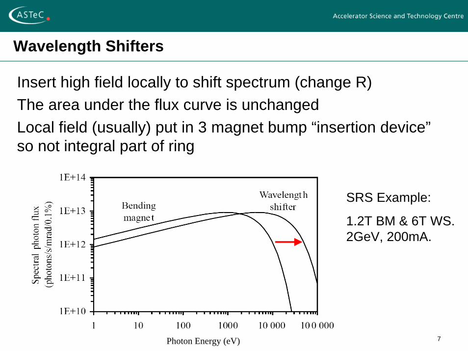
Wavelength Shifters
Insert high field locally to shift spectrum (change R)The area under the flux curve is unchangedLocal field (usually) put in 3 magnet bump “insertion device”so not integral part of ring
SRS Example:
1.2T BM & 6T WS. 2GeV, 200mA.
Photon Energy (eV)
8
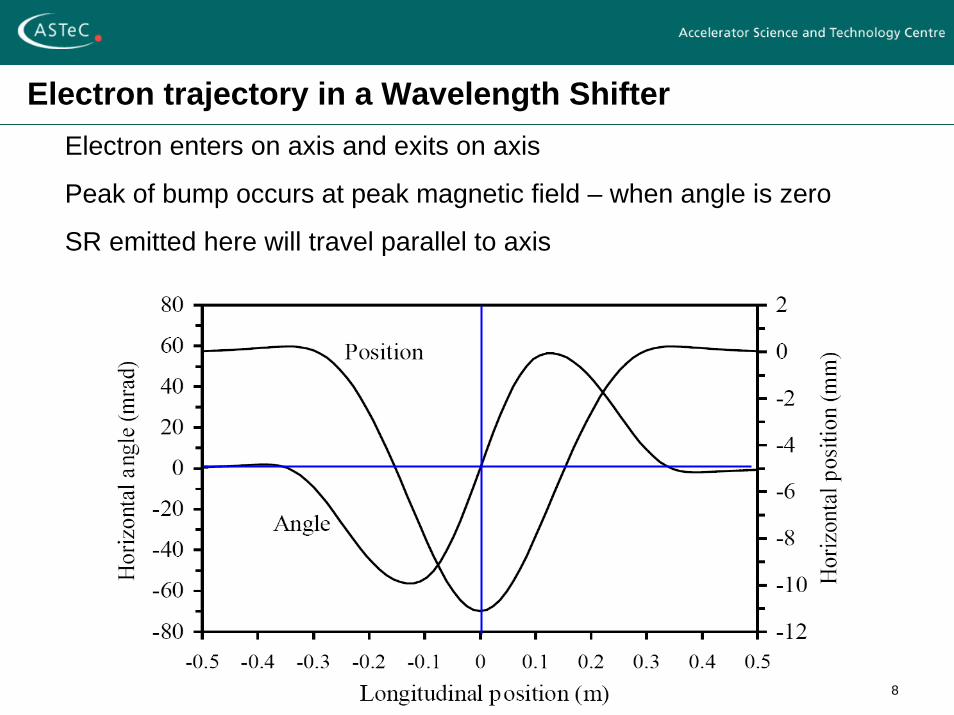
Electron trajectory in a Wavelength ShifterElectron enters on axis and exits on axis
Peak of bump occurs at peak magnetic field – when angle is zero
SR emitted here will travel parallel to axis
9
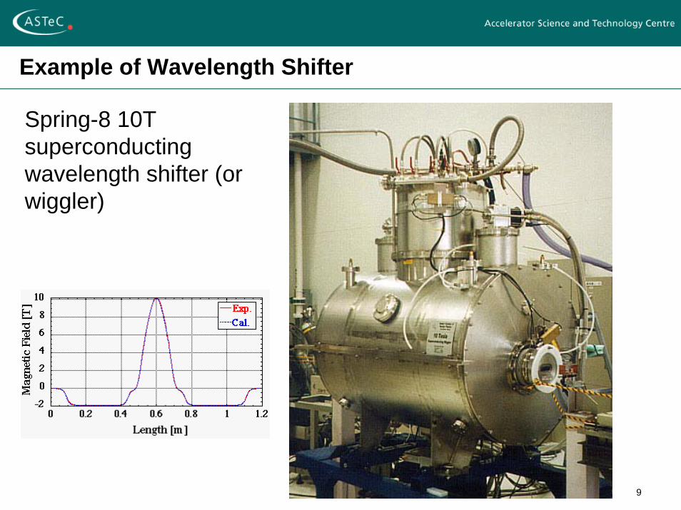
Example of Wavelength Shifter
Spring-8 10T superconducting wavelength shifter (or wiggler)
10
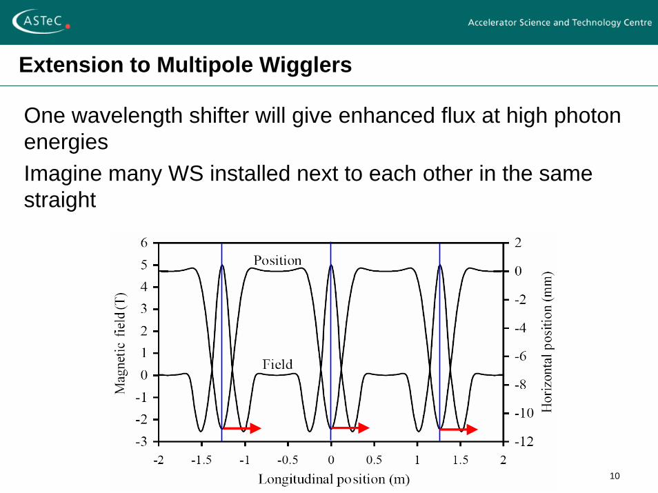
Extension to Multipole Wigglers
One wavelength shifter will give enhanced flux at high photon energiesImagine many WS installed next to each other in the same straight
11
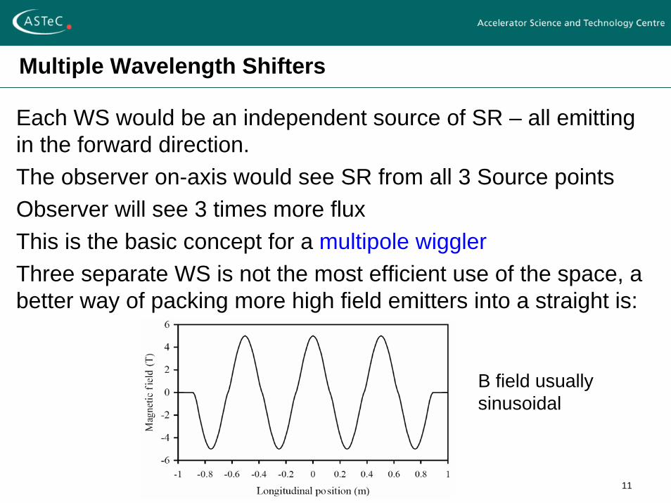
Multiple Wavelength Shifters
Each WS would be an independent source of SR – all emitting in the forward direction.The observer on-axis would see SR from all 3 Source pointsObserver will see 3 times more fluxThis is the basic concept for a multipole wigglerThree separate WS is not the most efficient use of the space, a better way of packing more high field emitters into a straight is:
B field usually sinusoidal
12
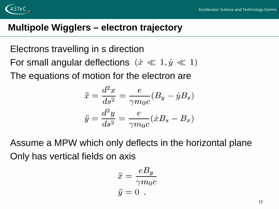
Multipole Wigglers – electron trajectory
Electrons travelling in s directionFor small angular deflectionsThe equations of motion for the electron are
Assume a MPW which only deflects in the horizontal planeOnly has vertical fields on axis
13
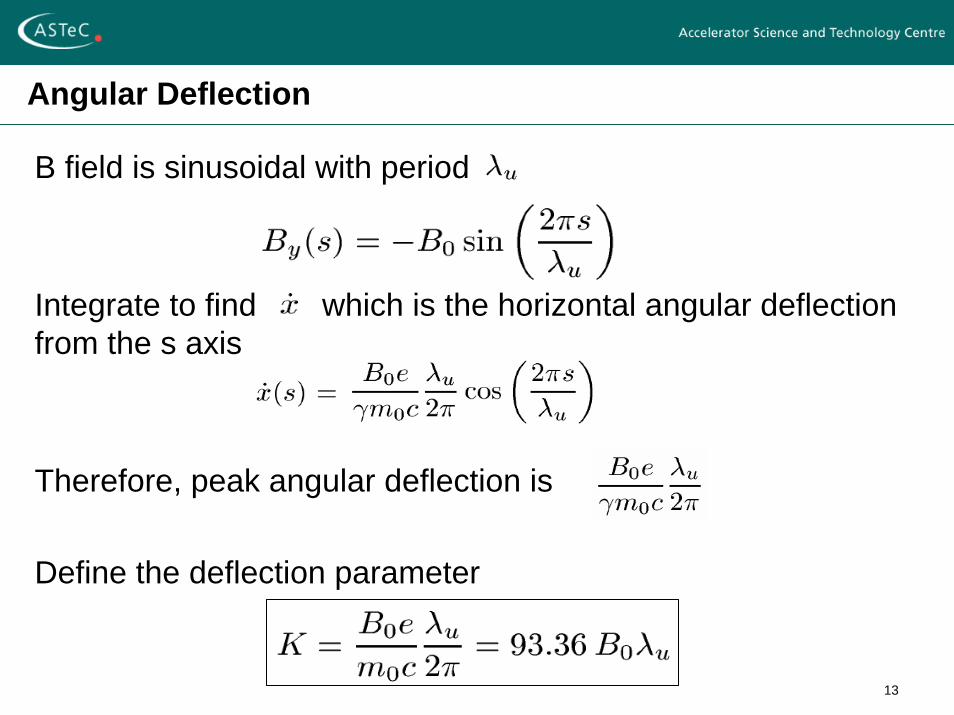
Angular Deflection
B field is sinusoidal with period
Integrate to find which is the horizontal angular deflection from the s axis
Therefore, peak angular deflection is
Define the deflection parameter
14
K Parameter
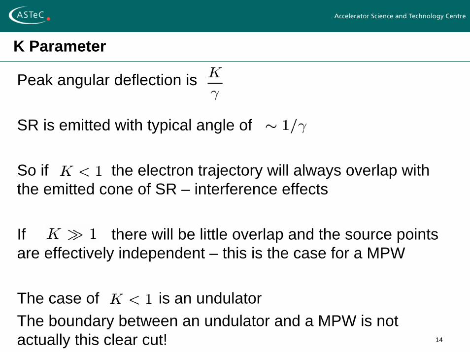
Peak angular deflection is
SR is emitted with typical angle of
So if the electron trajectory will always overlap with the emitted cone of SR – interference effects
If there will be little overlap and the source points are effectively independent – this is the case for a MPW
The case of is an undulatorThe boundary between an undulator and a MPW is not actually this clear cut!
15
Undulators: Condition for Interference
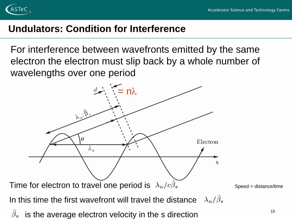
For interference between wavefronts emitted by the same electron the electron must slip back by a whole number of wavelengths over one period
Time for electron to travel one period is
In this time the first wavefront will travel the distance
is the average electron velocity in the s direction
Speed = distance/time
= nλ
16
Interference Condition
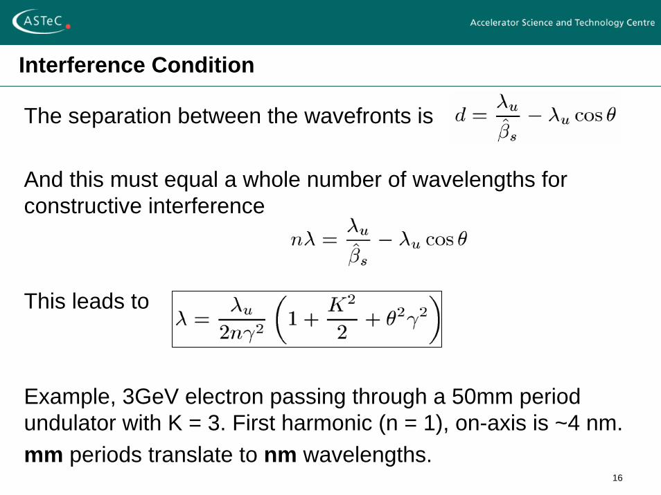
The separation between the wavefronts is
And this must equal a whole number of wavelengths for constructive interference
This leads to
Example, 3GeV electron passing through a 50mm period undulator with K = 3. First harmonic (n = 1), on-axis is ~4 nm.mm periods translate to nm wavelengths.
17
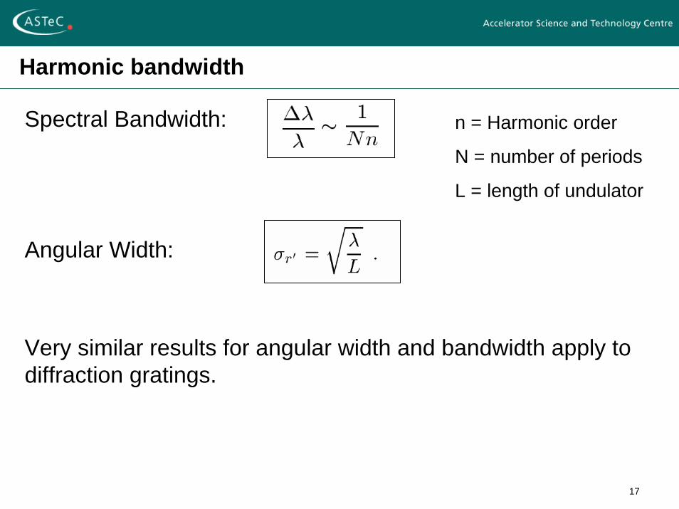
Harmonic bandwidth
Spectral Bandwidth:
Angular Width:
Very similar results for angular width and bandwidth apply to diffraction gratings.
n = Harmonic order
N = number of periods
L = length of undulator
18
When does an undulator become a wiggler?
As K increases the number of harmonics increasesAt high frequencies the spectrum smoothes out and takes on the shape of the bending magnet spectrumAt low frequencies distinct harmonics are still present and visibleThere is in fact no clear distinction between an undulator and a wiggler – it depends which bit of the spectrum you are observing
19
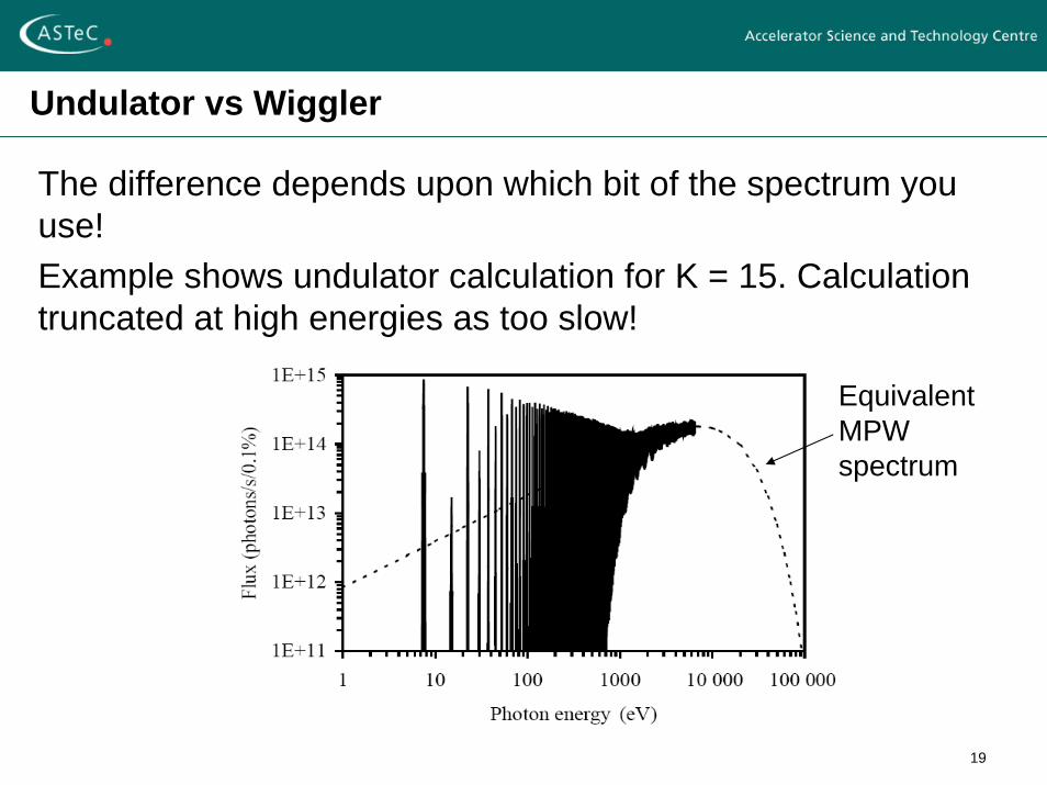
Undulator vs Wiggler
The difference depends upon which bit of the spectrum you use!Example shows undulator calculation for K = 15. Calculation truncated at high energies as too slow!
Equivalent MPW spectrum
20
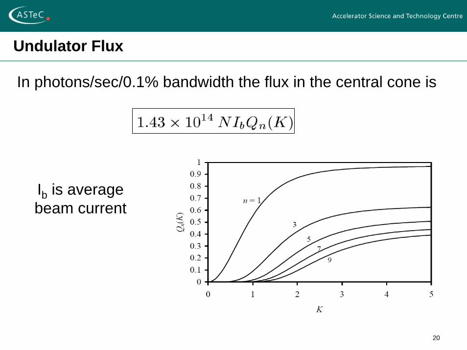
Undulator Flux
In photons/sec/0.1% bandwidth the flux in the central cone is
Ib is average beam current
21
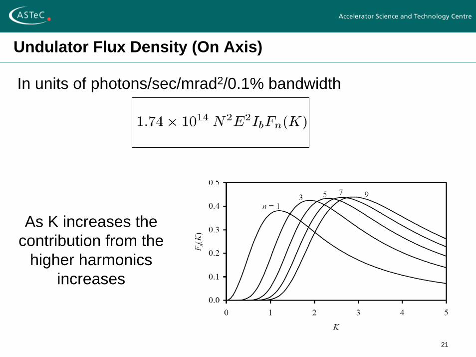
Undulator Flux Density (On Axis)
In units of photons/sec/mrad2/0.1% bandwidth
As K increases the contribution from the
higher harmonics increases
22
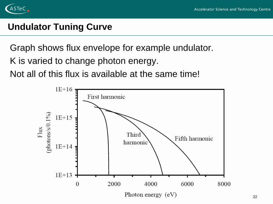
Undulator Tuning Curve
Graph shows flux envelope for example undulator.K is varied to change photon energy.Not all of this flux is available at the same time!
23
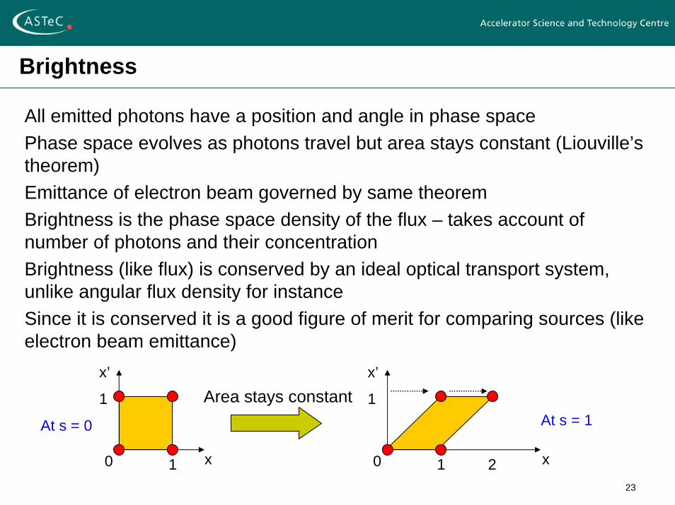
Brightness
All emitted photons have a position and angle in phase spacePhase space evolves as photons travel but area stays constant (Liouville’s theorem)Emittance of electron beam governed by same theoremBrightness is the phase space density of the flux – takes account of number of photons and their concentrationBrightness (like flux) is conserved by an ideal optical transport system, unlike angular flux density for instanceSince it is conserved it is a good figure of merit for comparing sources (like electron beam emittance)
x0 1
x’
1
At s = 0
x0 1
x’
1
2
At s = 1Area stays constant
24
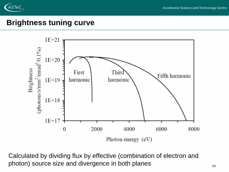
Brightness tuning curve
Calculated by dividing flux by effective (combination of electron and photon) source size and divergence in both planes
25
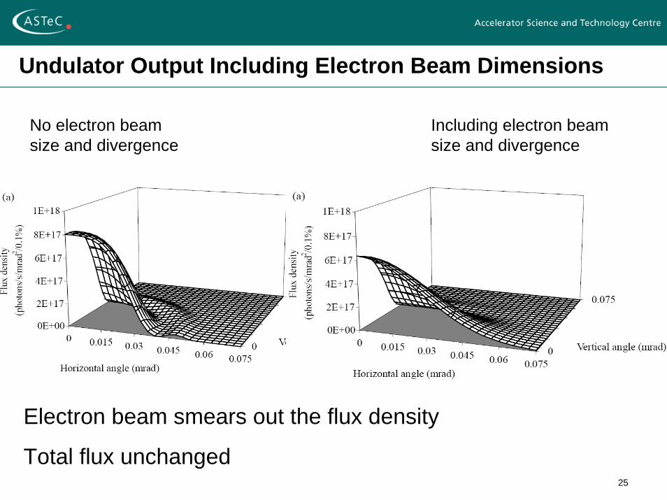
Undulator Output Including Electron Beam Dimensions
Including electron beam size and divergence
No electron beam size and divergence
Electron beam smears out the flux density
Total flux unchanged
26
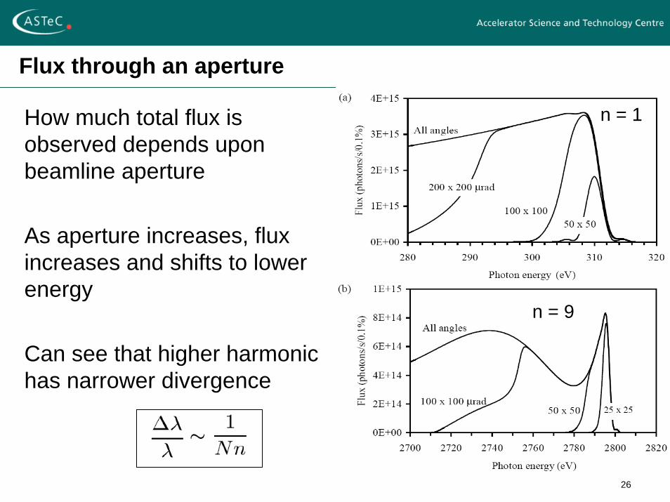
Flux through an aperture
How much total flux is observed depends upon beamline aperture
As aperture increases, flux increases and shifts to lower energy
Can see that higher harmonic has narrower divergence
n = 1
n = 9
27
Insertion Device Technology
To generate the magnetic field we can use:
Current carrying coils (Electromagnets)
Normal conducting or superconducting
Permanent Magnets
Both can be with or without iron
28
Permanent Magnet Materials
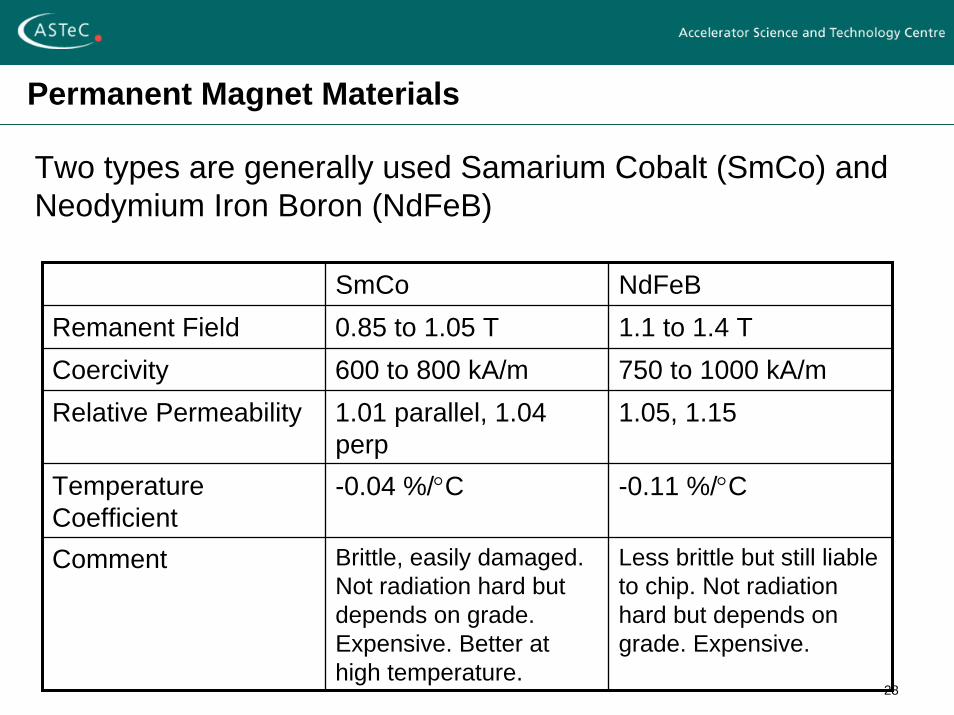
Two types are generally used Samarium Cobalt (SmCo) and Neodymium Iron Boron (NdFeB)
SmCo NdFeBRemanent Field 0.85 to 1.05 T 1.1 to 1.4 TCoercivity 600 to 800 kA/m 750 to 1000 kA/mRelative Permeability 1.01 parallel, 1.04
perp1.05, 1.15
Temperature Coefficient
-0.04 %/°C -0.11 %/°C
Comment Brittle, easily damaged. Not radiation hard but depends on grade. Expensive. Better at high temperature.
Less brittle but still liable to chip. Not radiation hard but depends on grade. Expensive.
29
Pure Permanent Magnet Undulators
A magnet which contains no iron or current carrying coils is said to be a pure permanent magnet (PPM)
To generate a sinusoidal field an ideal PPM would have two arrays of PM with the easy axis rotating through 360° per period along the direction of the electron beam
In practice this ideal situation is approximated by splitting the system into rectangular magnet blocks, M per period
30
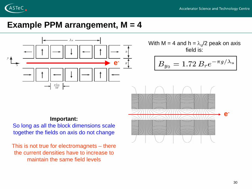
Example PPM arrangement, M = 4
e-
e-Important:
So long as all the block dimensions scale together the fields on axis do not change
This is not true for electromagnets – there the current densities have to increase to
maintain the same field levels
With M = 4 and h = λu/2 peak on axis field is:
31
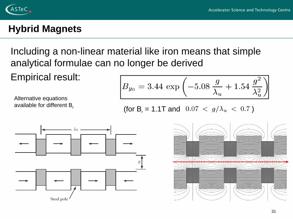
Hybrid Magnets
Including a non-linear material like iron means that simple analytical formulae can no longer be derivedEmpirical result:
(for Br = 1.1T and )Alternative equations available for different Br
32
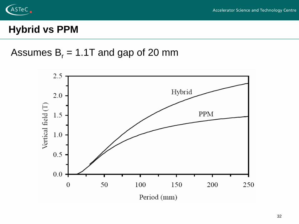
Hybrid vs PPM
Assumes Br = 1.1T and gap of 20 mm
33
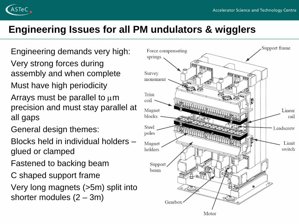
Engineering Issues for all PM undulators & wigglers
Engineering demands very high:Very strong forces during assembly and when completeMust have high periodicityArrays must be parallel to μm precision and must stay parallel at all gapsGeneral design themes:Blocks held in individual holders –glued or clampedFastened to backing beamC shaped support frameVery long magnets (>5m) split into shorter modules (2 – 3m)
34
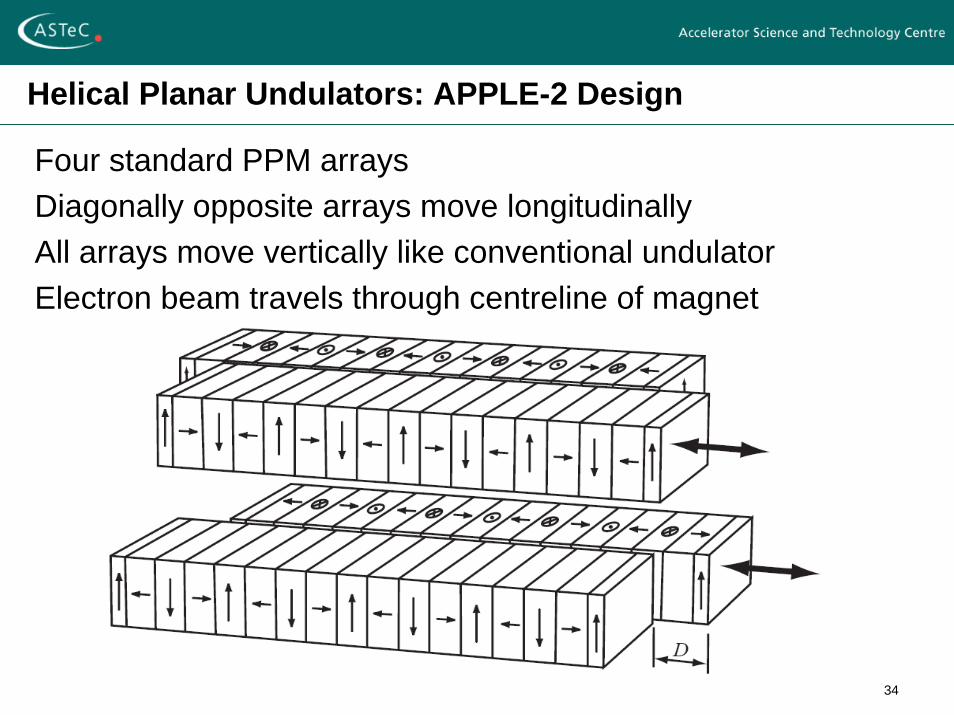
Helical Planar Undulators: APPLE-2 Design
Four standard PPM arraysDiagonally opposite arrays move longitudinallyAll arrays move vertically like conventional undulatorElectron beam travels through centreline of magnet
35
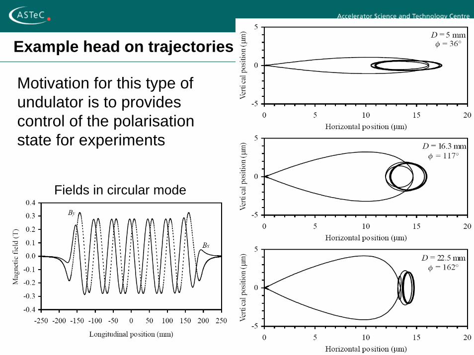
Example head on trajectories
Motivation for this type of undulator is to provides control of the polarisation state for experiments
Fields in circular mode
36
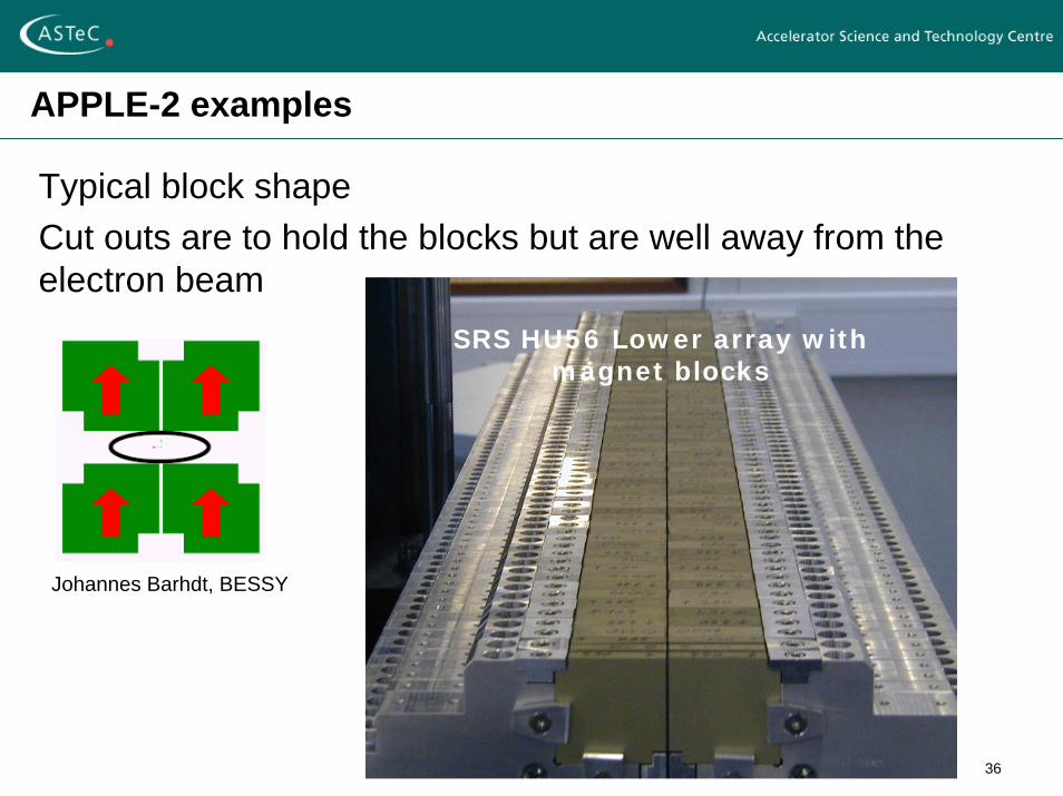
APPLE-2 examples
Typical block shapeCut outs are to hold the blocks but are well away from the electron beam
Johannes Barhdt, BESSY
SRS HU56 Lower array with magnet blocks
37
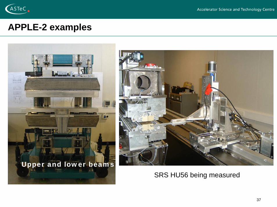
APPLE-2 examples
Upper and lower beams
SRS HU56 being measured
38
In Vacuum Undulators
Minimum Magnet gap sets performance of deviceMagnet gap set by needs of electron beamIn practice set by vacuum chamberExample:
electron beam needs 10mm vertical spacevacuum chamber walls 2mm thickallowance for alignment tolerances etc 1mmMinimum magnet gap 15mm
One solution is to put magnets inside the vacuum systemVacuum pressure must be maintained otherwise electrons will be lost – affects all users
39
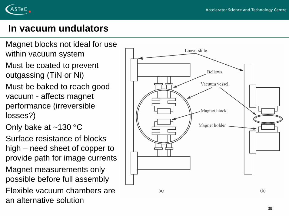
In vacuum undulatorsMagnet blocks not ideal for use within vacuum systemMust be coated to prevent outgassing (TiN or Ni)Must be baked to reach good vacuum - affects magnet performance (irreversible losses?)Only bake at ~130 °CSurface resistance of blocks high – need sheet of copper to provide path for image currentsMagnet measurements only possible before full assemblyFlexible vacuum chambers are an alternative solution
40
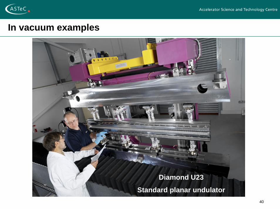
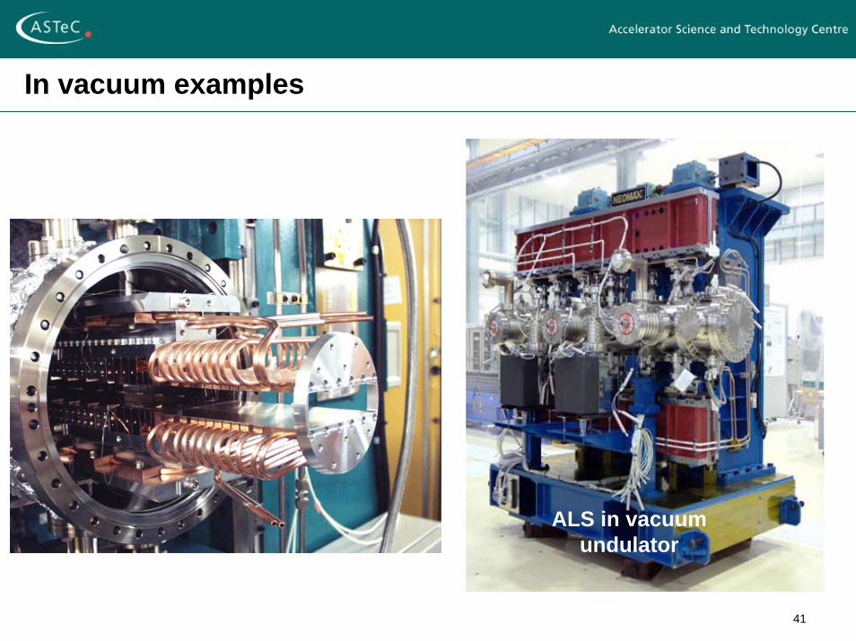
In vacuum examples
Diamond U23
Standard planar undulator
41
In vacuum examples
ALS in vacuum undulator
42
The Future …
The field of insertion devices continues to evolve:Higher fields are being proposed by the use of cold permanent magnetsNew challenges are presented by the fourth generation light sources – single pass free electron lasers
Insertion Devices are not just used in light sources:The proposed International Linear Collider relies on ~400m of superconducting wiggler and ~200m of superconducting undulatorThe LHC uses undulators to generate SR for diagnostic purposes
43
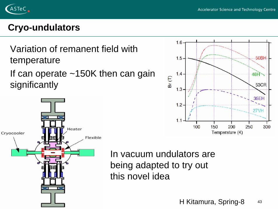
Cryo-undulators
Variation of remanent field with temperatureIf can operate ~150K then can gain significantly
In vacuum undulators are being adapted to try out this novel idea
H Kitamura, Spring-8
44
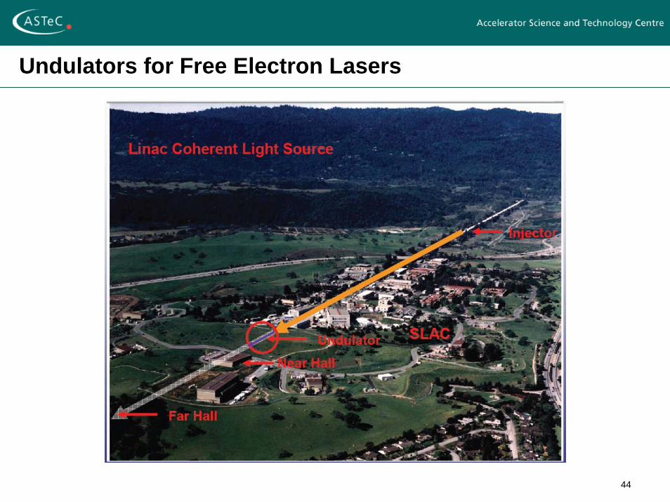
Undulators for Free Electron Lasers
45
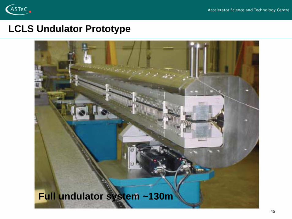
LCLS Undulator Prototype
Full undulator system ~130m
46
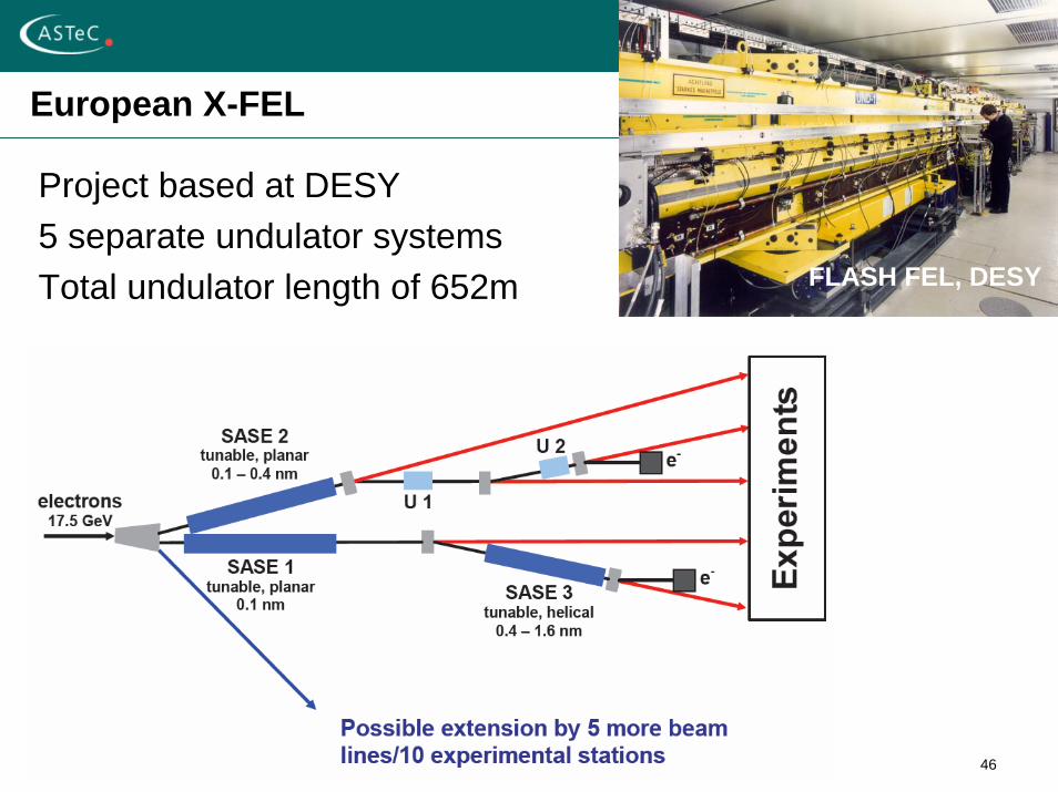
European X-FEL
Project based at DESY5 separate undulator systemsTotal undulator length of 652m FLASH FEL, DESY
47
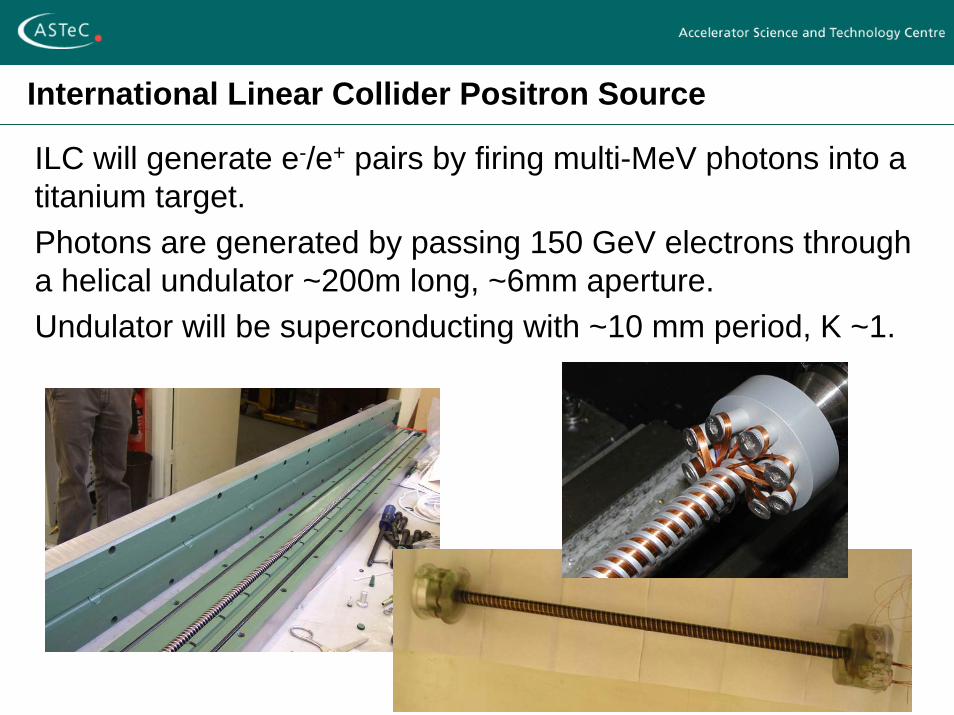
International Linear Collider Positron Source
ILC will generate e-/e+ pairs by firing multi-MeV photons into a titanium target.Photons are generated by passing 150 GeV electrons through a helical undulator ~200m long, ~6mm aperture.Undulator will be superconducting with ~10 mm period, K ~1.
48
Summary
This has been a very brief summary of some of the features & issues associated with insertion devicesMany items have not been covered, eg
magnet measurementsfield quality correctionbeam dynamics effects of IDsmany novel designs for altering the photon output to suit the experimental requirements
Insertion Devices are now a mature subject but new technologies and innovative designs continue to emerge to push the subject forward
49
Further Reading
J A Clarke, “The Science and Technology of Undulators and Wigglers”, Oxford University Press, 2004.
H Onuki & P Elleaume, “Undulators, Wigglers and their Applications”, Taylor and Francis, 2003.
R P Walker, “Insertion Devices: Undulators and Wigglers”, CAS 1996, Report CERN 98-04.