Jig and fixture
16
Department of Mechanical Engineering- SOE CUSAT Drilling jigs and milling fixtures Jig & fixture design Design objective Combination of more than one processes Automation of processes Increase productivity and efficiency Design criteria Must last long Easy to maintain Minimum weight Find answers to questions What are the hole-location tolerances on the part? Is there any obstruction that may hinder the loading & unloading the work piece? Where are the free flow movement of scrap chips? What is the material and its hardness? Where to locate? Where to clamp? Where are the working areas? What is minimum machining accuracy? What machines to be used & its min. accuracy? Jigs The two types of jigs that are in general use are (1) clamp jig (2) box jig. Clamp Jig 1 [email protected]
-
Upload
pramodkbcusat -
Category
Documents
-
view
159 -
download
9
description
a brief introduction to different jigs anf fixtures
Transcript of Jig and fixture
Department of Mechanical Engineering- SOE CUSAT
Drilling jigs and milling fixtures
Jig & fixture design
Design objective
Combination of more than one processes Automation of processes Increase productivity and efficiency
Design criteria
Must last long Easy to maintain Minimum weight
Find answers to questions
What are the hole-location tolerances on the part? Is there any obstruction that may hinder the loading & unloading the work piece? Where are the free flow movement of scrap chips? What is the material and its hardness? Where to locate? Where to clamp? Where are the working areas? What is minimum machining accuracy? What machines to be used & its min. accuracy?
Jigs
The two types of jigs that are in general use are
(1)clamp jig (2) box jig.
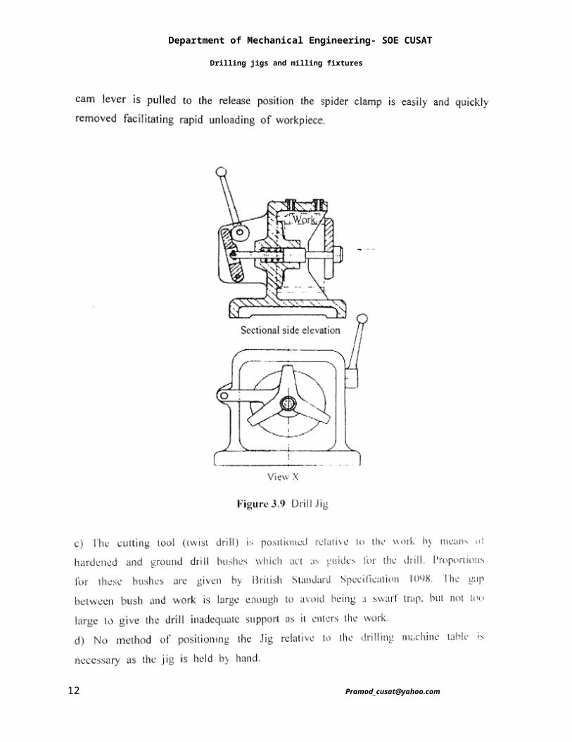
Clamp JigThis device derives its name from the fact that it usually resembles some form of clamp. It is adapted for use on workpieces on which the axes of all the holes that are to be drilled are parallel. Clamp jigs are sometimes called open jigs. A simple example of a clamp jig is a design for drilling holes that are all the same size
Department of Mechanical Engineering- SOE CUSAT
Drilling jigs and milling fixtures
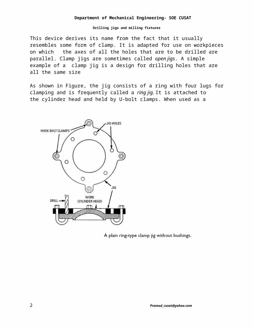
As shown in Figure, the jig consists of a ring with four lugs for clamping and is frequently called a ring jig. It is attached to the cylinder head and held by U-bolt clamps. When used as a
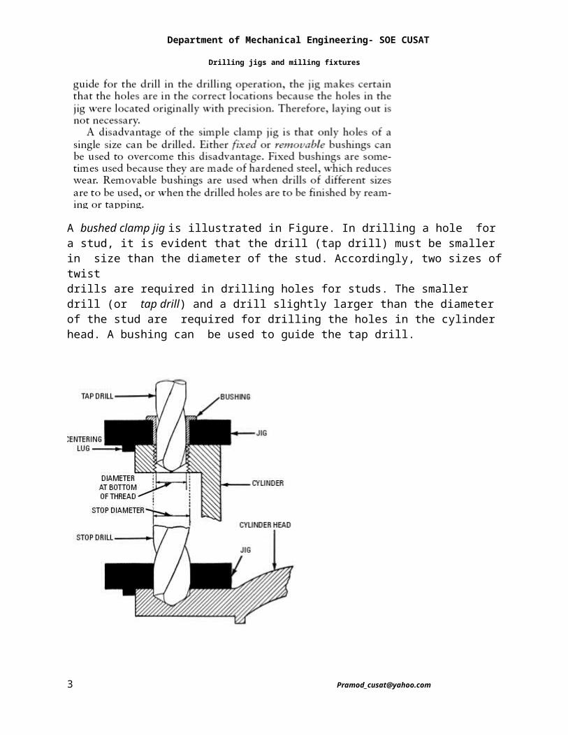
A bushed clamp jig is illustrated in Figure. In drilling a hole for a stud, it is evident that the drill (tap drill) must be smaller in size than the diameter of the stud. Accordingly, two sizes of twistdrills are required in drilling holes for studs. The smaller drill (or tap drill) and a drill slightly larger than the diameter of the stud are required for drilling the holes in the cylinder head. A bushing can be used to guide the tap drill.
Department of Mechanical Engineering- SOE CUSAT
Drilling jigs and milling fixtures
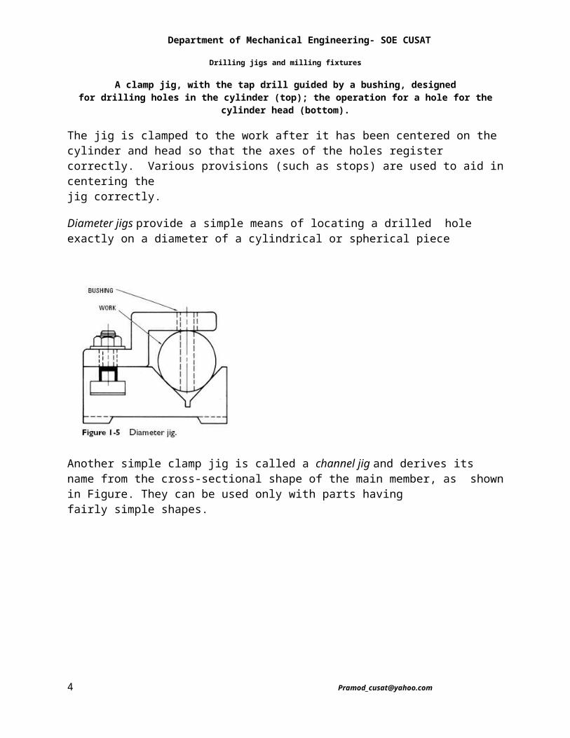
A clamp jig, with the tap drill guided by a bushing, designedfor drilling holes in the cylinder (top); the operation for a hole for the
cylinder head (bottom).
The jig is clamped to the work after it has been centered on the cylinder and head so that the axes of the holes register correctly. Various provisions (such as stops) are used to aid in centering thejig correctly.
Diameter jigs provide a simple means of locating a drilled hole exactly on a diameter of a cylindrical or spherical piece
Department of Mechanical Engineering- SOE CUSAT
Drilling jigs and milling fixtures
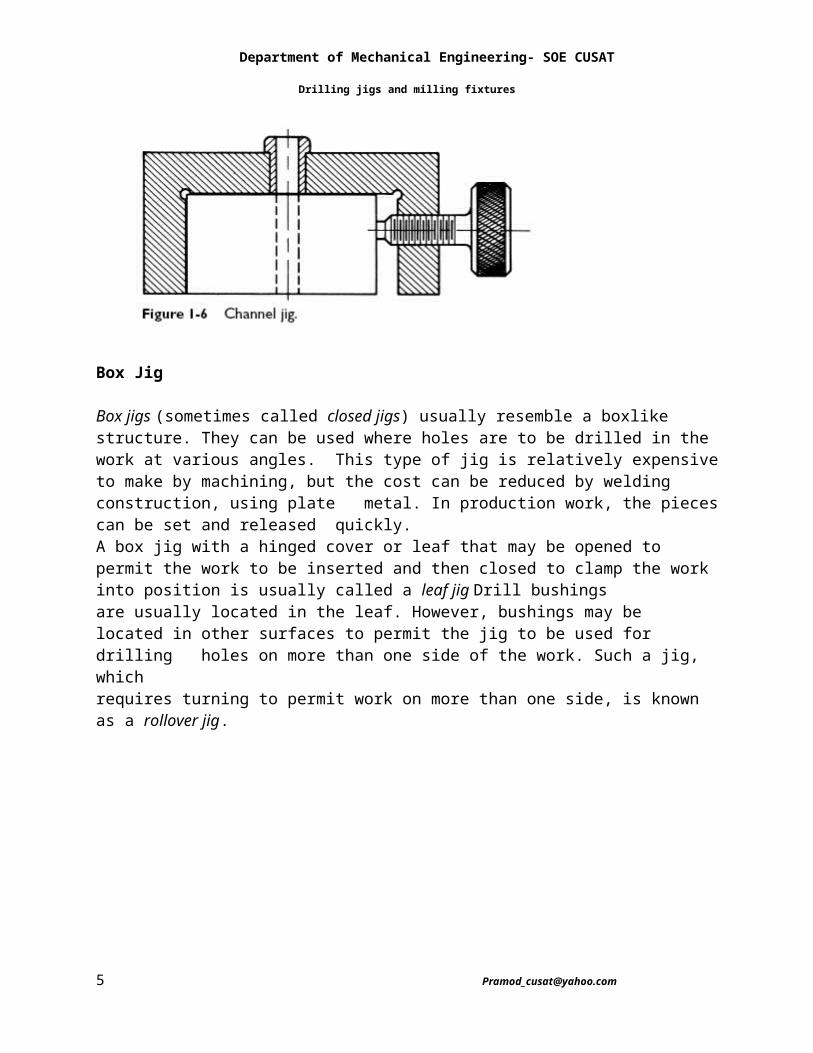
Another simple clamp jig is called a channel jig and derives its name from the cross-sectional shape of the main member, as shown in Figure. They can be used only with parts havingfairly simple shapes.
Box Jig
Box jigs (sometimes called closed jigs) usually resemble a boxlike structure. They can be used where holes are to be drilled in the work at various angles. This type of jig is relatively expensive to make by machining, but the cost can be reduced by welding construction, using plate metal. In production work, the pieces can be set and released quickly.A box jig with a hinged cover or leaf that may be opened to permit the work to be inserted and then closed to clamp the work into position is usually called a leaf jig Drill bushingsare usually located in the leaf. However, bushings may be located in other surfaces to permit the jig to be used for drilling holes on more than one side of the work. Such a jig, which
Department of Mechanical Engineering- SOE CUSAT
Drilling jigs and milling fixtures
requires turning to permit work on more than one side, is known as a rollover jig.
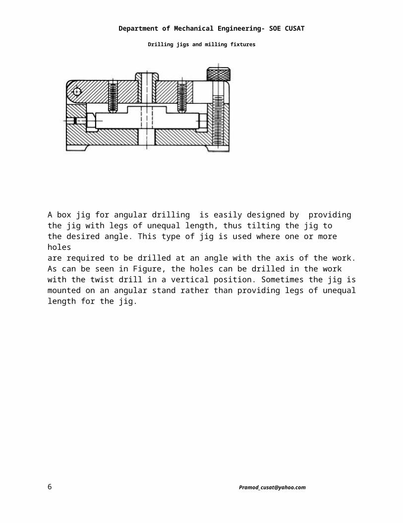
A box jig for angular drilling is easily designed by providing the jig with legs of unequal length, thus tilting the jig to the desired angle. This type of jig is used where one or more holesare required to be drilled at an angle with the axis of the work. As can be seen in Figure, the holes can be drilled in the work with the twist drill in a vertical position. Sometimes the jig ismounted on an angular stand rather than providing legs of unequal length for the jig.
Department of Mechanical Engineering- SOE CUSAT
Drilling jigs and milling fixtures
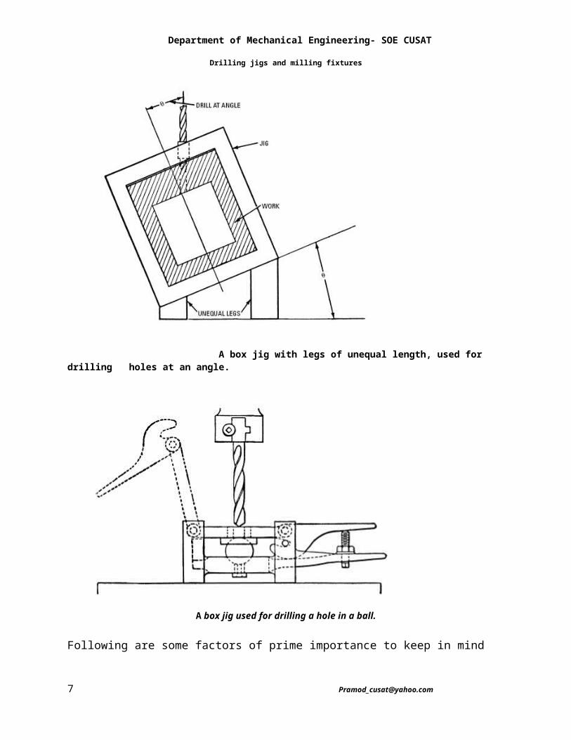
A box jig with legs of unequal length, used for drilling holes at an angle.
A box jig used for drilling a hole in a ball.
Following are some factors of prime importance to keep in mindwith jigs:• Proper clamping of the work• Support of the work while machining
Department of Mechanical Engineering- SOE CUSAT
Drilling jigs and milling fixtures
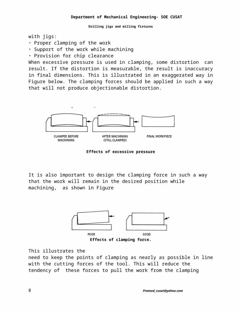
• Provision for chip clearanceWhen excessive pressure is used in clamping, some distortion can result. If the distortion is measurable, the result is inaccuracy in final dimensions. This is illustrated in an exaggerated way in Figure below. The clamping forces should be applied in such a waythat will not produce objectionable distortion.
Effects of excessive pressure
It is also important to design the clamping force in such a way that the work will remain in the desired position while machining, as shown in Figure
Effects of clamping force.
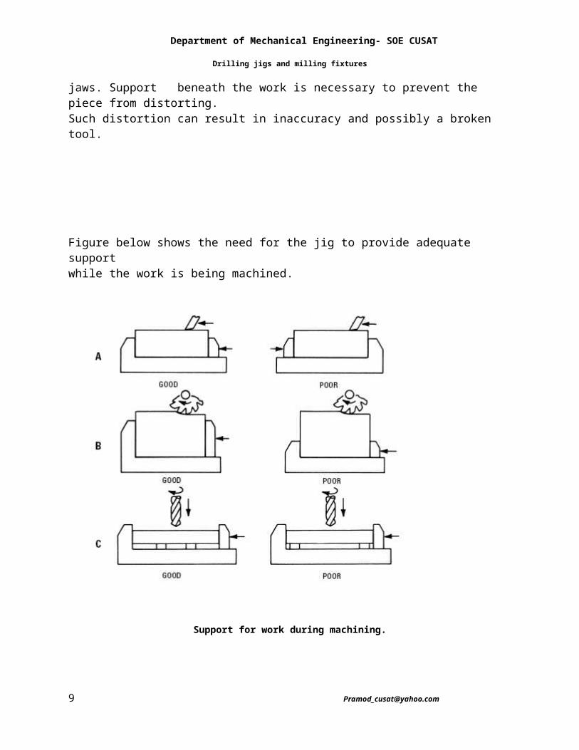
This illustrates theneed to keep the points of clamping as nearly as possible in line with the cutting forces of the tool. This will reduce the tendency of these forces to pull the work from the clamping jaws. Support beneath the work is necessary to prevent the piece from distorting.Such distortion can result in inaccuracy and possibly a broken tool.
Figure below shows the need for the jig to provide adequate supportwhile the work is being machined.
Department of Mechanical Engineering- SOE CUSAT
Drilling jigs and milling fixtures
Support for work during machining.
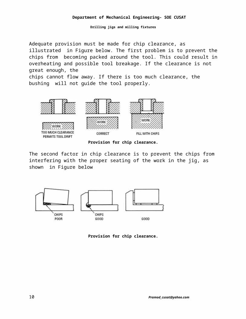
Adequate provision must be made for chip clearance, as illustrated in Figure below. The first problem is to prevent the chips from becoming packed around the tool. This could result in overheating and possible tool breakage. If the clearance is not great enough, thechips cannot flow away. If there is too much clearance, the bushing will not guide the tool properly.
Provision for chip clearance.
Department of Mechanical Engineering- SOE CUSAT
Drilling jigs and milling fixtures
The second factor in chip clearance is to prevent the chips from interfering with the proper seating of the work in the jig, as shown in Figure below
Provision for chip clearance.
Department of Mechanical Engineering- SOE CUSAT
Drilling jigs and milling fixtures
Department of Mechanical Engineering- SOE CUSAT
Drilling jigs and milling fixtures
Department of Mechanical Engineering- SOE CUSAT
Drilling jigs and milling fixtures
A milling fixture
Department of Mechanical Engineering- SOE CUSAT
Drilling jigs and milling fixtures
Department of Mechanical Engineering- SOE CUSAT
Drilling jigs and milling fixtures