
JIB CRANES WITH AN ARTICULATED ARM - Light Cranes · donati sollevamenti s.r.l. via roma, 55 -...
61
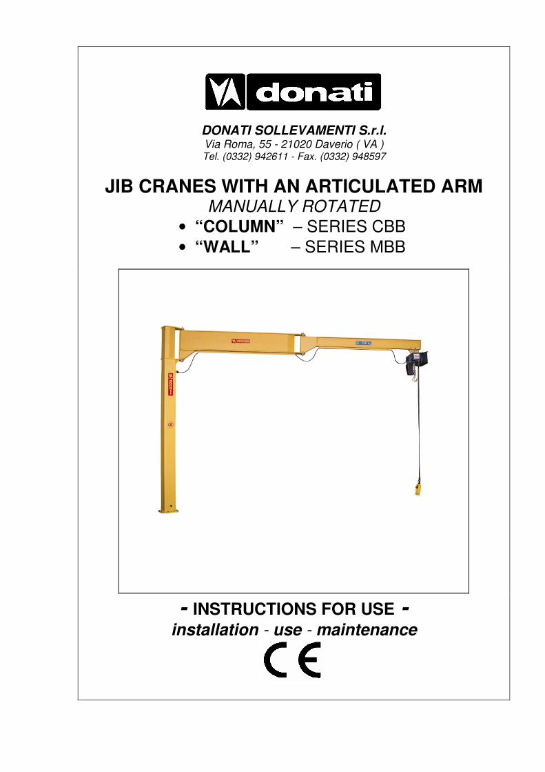
DONATI SOLLEVAMENTI S.r.l. Via Roma, 55 - 21020 Daverio ( VA ) Tel. (0332) 942611 - Fax. (0332) 948597 JIB CRANES WITH AN ARTICULATED ARM MANUALLY ROTATED • “COLUMN” – SERIES CBB • “WALL” – SERIES MBB - INSTRUCTIONS FOR USE - installation - use - maintenance
Transcript of JIB CRANES WITH AN ARTICULATED ARM - Light Cranes · donati sollevamenti s.r.l. via roma, 55 -...
DONATI SOLLEVAMENTI S.r.l. Via Roma, 55 - 21020 Daverio ( VA ) Tel. (0332) 942611 - Fax. (0332) 948597
JIB CRANES WITH AN ARTICULATED ARM MANUALLY ROTATED
• “COLUMN” – SERIES CBB
• “WALL” – SERIES MBB
- INSTRUCTIONS FOR USE -
installation - use - maintenance
DONATI SOLLEVAMENTI S.r.l. - Via Roma, 55 - 21020 Daverio (VA) - Tel. 0332 942611 - Fax. 0332 948597
II
INDEX
Pag.
1. PRELIMINARY INFORMATION 1 1.1 Contents and use of the manual 1 1.2 Symbols: meaning and use 1 1.3 Co-operation with the user 2 1.4 Conformity with safety regulations 2 1.5 The manufacturer’s responsibility and the warranty 3
2. DESCRIPTION OF THE MACHINE AND TECHNICAL INFORMATION 4
2.1 The manually rotated jib cranes with an articulated arm 4 2.1.1 Intended use - Foreseen use - Designated use 4 2.1.2 Constraints when installing 4 2.1.3 The composition of the jib cranes 4 2.2 Technical information and service conditions 7 2.2.1 Safety reference list 7 2.2.2 Protection and insulation of electrical parts 7 2.2.3 Electrical power supply 7 2.2.4 Environment conditions of use 7 2.2.5 Noise - Vibrations 8 2.2.6 Criteria of use and conditions of use 8 2.2.7 Characteristics and technical data - Weights - Reactions on constraints 9
3. SAFETY AND ACCIDENT PREVENTION 13 3.1 Qualifications of qualified operators 13 3.2 General safety regulations 14 3.3 Safety symbols 14 3.4 Warning about remaining risks 16 3.5 Safety measures and instructions 17 3.5.1 Control devices 17 3.5.2 Safety and emergency devices 17 3.5.3 Warning and signalling devices - List of labels 18
4. HANDLING - INSTALLATION - PUTTING INTO OPERATION 19 4.1 General notes at delivery 19 4.2 Packing, transportation and handling 20 4.2.1 Standard packing 20 4.2.2 Transportation 20 4.2.3 Handling 21 4.2.4 Removing the packing and/or check of the crane parts 21 4.3 Installation of the jib crane 22 4.3.1 Duties and responsibilities of the installer 22 4.3.2 Preparing the place of installation 23 4.3.3 Assembly of the column – For CBB column-mounted cranes 24 4.3.4 Assembly of the bracket – For MBB wall-mounted cranes 26 4.3.5 Assembly of the arm – For CBB column-mounted cranes and MBB wall-mounted cranes 28 4.3.6 Assembly of the electric system with the connector block 30 4.3.7 Assembly of the trolley/hoist 31 4.4 Putting the machine into operation 32 4.4.1 Preliminary operations – Adjustments and test runs 33 4.4.2 Inspection of the jib crane – Suitability for use 33 4.5 Out of service 34 4.5.1 Storage and conservation of parts 36 4.5.2 Reuse after storage 36 4.1 General notes at delivery 36

DONATI SOLLEVAMENTI S.r.l. - Via Roma, 55 - 21020 Daverio (VA) - Tel. 0332 942611 - Fax. 0332 948597
III
INDEX
Pag.
5. FUNCTIONING AND USE OF THE JIB CRANE 37 5.1 Functions of the jib crane 37 5.1.1 Intended use - Foreseen use - Designated use 37 5.1.2 Permitted loads, loads not permitted 38 5.1.3 Lifting accessories 38 5.2 Operating conditions 39 5.2.1 Operating environment 39 5.2.2 Danger zones and people exposed to risk 39 5.2.3 Illumination of the work area 40 5.2.4 The operator 40 5.2.5 The lifting capacity of the jib crane 40 5.2.6 Manoeuvres:lifting and arms rotation 41 5.2.7 Safety devices 41 5.3 Setting up - Starting the jib crane 42 5.4 Switching off at the end of use 42 5.5 Criteria and precautions of use 42 5.6 Constraints of use 43 5.6.1 Use not intended and not allowed - Foreseeable and unforeseeable inappropriate use 43
6. MAINTENANCE OF THE JIB CRANE 45 6.1 Safety precautions 45 6.2 The qualifications of maintenance staff 47 6.3 Maintenance plan 50 6.3.1 Daily and periodical maintenance 50 6.3.2 Frequency and deadlines for maintenance work 51 6.3.3 Check of efficiency of parts and components 52 6.3.4 Cleaning and lubrication of the jib crane 54 6.4 Adjusting and regulating 55 6.4.1 Adjusting the rotation brake of the crane arm 55 6.5 Breakdowns and solutions 56 6.5.1 Main types of failure or breakdowns and possible solutions 56 6.5.2 Authorised staff for intervention in case of breakdown 56 6.5.3 Putting out of service 56 6.6 Dismantling, disposal and scrapping 56
7. SPARE PARTS 57
8. THE CHECKS REGISTER 57

DONATI SOLLEVAMENTI S.r.l. - Via Roma, 55 - 21020 Daverio (VA) - Tel. 0332 942611 - Fax. 0332 948597
IV
LETTER ON DELIVERY
Dear customer, We thank you for having chosen a DONATI jib crane and we are happy to provide you with this technical publication which aims at achieving the maximum productivity of the machine in the safest way possibile.
•••• DONATI SOLLEVAMENTI S.r.l. produces jib cranes and relevant accessories, using a QUALITY SYSTEM in accordance with the UNI EN ISO 9001 regulations: 2000 certified by ICIM with N° 114.
•••• This documentation, orginally written in Italian, takes into consideration the EN 292 norm - 1° part point 3.20 and 2° part point 5 and has been created in compliance with the requirements 1.7.4 and 4.4.2. of the Directive 98/37CE ex 89/392CEE and successive amendments.
•••• We would like you to read this manual carefully and to provide the staff who will work the jib crane with a copy of it.
DONATI SOLLEVAMENTI S.r.l.
Example certification CISQ-ICIM
Example certification IQ Net
DONATI SOLLEVAMENTI S.r.l. - Via Roma, 55 - 21020 Daverio (VA) - Tel. 0332 942611 - Fax. 0332 948597
1
1. - PRELIMINARY INFORMATION
1.1 Contents and use of the manual § This technical publication,identified by the code MAN142001G, refers to “Jib cranes, manually rotated with an articulated arm, in CBB series column-mounted model or MBB series wall-mounted, built and put on the market by the company :
DONATI SOLLEVAMENTI S.r.l. Via Roma, 55 - 21020 Daverio (VA) Tel. 0332.942611 - Fax. 0332.948597
§ It refers to their “intended use”, to their technical functional and performance characteristics and to the relevant installation, use and maintenance instructions. It is intended for: • the supervisor of the factory, workshop, building site • the staff in charge of transporting, handling and installation of the equipment • the operators of the jib crane • the maintenance staff This manual must be kept by the person in charge of the above mentioned duties in a suitable place, so that it is always available for consultation and kept in the best possible state. If the manual is lost or becomes unusable, replacement documentation should be requested directly from the manufacturer by quoting the code of this manual.
The manufacturer retains the material and intellectual rights of this publication and forbids the divulgation and duplication, even partial, without prior written permission.
Copyright© 2006 by DONATI SOLLEVAMENTI S.r.l.
1.2 Symbols: meaning and use
§ In this manual certain symbols are used to focus the reader’s attention and underline some particularly important aspects of the subject. The following table shows the list and meaning of the symbols used in the manual.
SYMBOL MEANING EXPLANATION, ADVICE, NOTES
Danger
•••• Indicates a danger with risk of accident, possibly fatal. •••• Failure to follow the attached instructions can cause a situation of
serious danger for the safety of the operator and for people in the vicinity!
•••• Follow the instructions scrupulously!
Warning
•••• Represents a warning note of attention of.possible deterioration of the jib or of a personal object of the operator.
•••• Important warning which requires one’s utmost care.
Warning / Note •••• Indicates a warning or a note about key functions or useful information.
•••• Visual observation
•••• Action to be
taken
•••• A printed eye can indicate to the reader that : a) He should proceed to a visual observation. b) He should proceed to the operating sequence. c) It is necessary to take a reading, to check a signal, etc.
DONATI SOLLEVAMENTI S.r.l. - Via Roma, 55 - 21020 Daverio (VA) - Tel. 0332 942611 - Fax. 0332 948597
2
1.3 Co-operation with the user This manual reflects the configuration of the machine at the time the machine was put on the market. Any change to the manual, a copy of which will be sent to the customer by the manufacturer, shall be kept together with the manual. The manufacturer is willing to supply its customers with any additional information they may require, and welcomes any suggestions aimed at improving the manual so that it corresponds better to the customer’s needs. If the jib crane is no longer to be used the main user is invited to deliver, with the hoist, this manual and the relevant documentation enclosed with it (declarations, schemes, control register etc.) 1.4 Conformity with safety regulations § The jib crane was designed and produced following the “Essential Safety Requirements” of Enclosure I of the Community Directive 98/37/EC ex 89/392/EEC and successive amendments 91/368/EEC, 93/44/EEC and 93/68/EEC, denominated Machines Directive, transposed into Italian legislation with DPR N° 459 of 24.07.96. Regarding what was stated in Enclosure II of the Directive 98/37/CE, the crane can be put on the market in the following ways:
A) Complete, or capable of functioning independently, having the CE Mark and the EC Declaration of Conformity - Enclosure II A.
B) Incomplete as destined to be incorporated in another machine and/or to be completed (i.e.: hoist) by the Customer In this case, in accordance with Article 4 - paragraph 2 of the Directive 98/37/CE, the jib crane does not carry the CE Mark and is supplied with the Declaration of the Manufacturer - Enclosure II B.
example CE Declaration CE of Conformoty Enclosure II A
example Declaration by the Manufacturer Enclosure II B
DONATI SOLLEVAMENTI S.r.l. - Via Roma, 55 - 21020 Daverio (VA) - Tel. 0332 942611 - Fax. 0332 948597
3
1.5 The manufacturer’s responsibility and the warranty § With reference to the contents of this manual DONATI SOLLEVAMENTI S.r.l. declines any responsibility in case of: • use of the jib crane contrary to the national safety and accident prevention laws • erroneous choice of the building site or buildings in which the jib crane is to be operated • voltage and power supply faults • lack of or erroneous observation of the instructions supplied in this manual • non-authorised modifications to the machine • use (of the machine) by untrained or unsuitable staff § To be able to use the warranty, the certification of which is shown below, the Customer must scrupulously follow the instructions indicated in this manual, and in particular : • always work within the use limits of the jib crane • always carry out constant, diligent maintenance • appoint operators of proven capability, who have been adequately trained for the job to use the machine • use solely original spare parts indicated by the manufacturer
•The intended use and configurations of the hoist are the only ones allowed. Do not try to use the hoist disregarding the supplied instructions. •The instructions in this manual do not replace but add to the obligations regarding the current legislation for accident prevention standards.
CERTIFICATE OF WARRANTY •••• DONATI SOLLEVAMENTI S.r.l. is the “Manufacturer” of the column-mounted jib cranes with an
articulated arm series CBB and wall-mounted jib cranes with an articulated arm series MBB, the subject of this technical publication.
•••• La DONATI SOLLEVAMENTI S.r.l. carries out the check on manufacturing regarding the “Quality system” of the company by ICIM with N° 114, according to the standard UNI EN ISO 9001: 2000.
All jib cranes, series CBB and MBB, are covered by the following warranty formula:
1. The warranty of the machine lasts for 36 months from delivery, attested to by the date of the invoice, taking into account the specifications and exclusions outlined as will follow and except for different explicit agreements between the parties. It is subject to the reporting by registered letter, within 8 days of the discovery of faults and the recognition of the existence of these by DONATI SOLLEVAMENTI S.r.l. 2. The warranty covers exclusively the resulting faulty parts from causes attributable to DONATI SOLLEVAMENTI S.r.l. and includes the replacement or repair of the faulty part excluding the dismantling, reassembly and despatch costs. The parts which DONATI SOLLEVAMENTI S.r.l. recognizes as faulty will have free despatch from the factory situated in Daverio (VA). 3. For components provided by third parties (commercial, electrical, mechanical and electromechanical components) the prevailing warranty conditions are those of the respective manufacturers. 4. Parts damaged during transportation or handling, as well as those subject to normal wear and tear (e.g. gaskets) and/or to perishing by atmospheric or environmental agents are excluded from the warranty. Damage from lack of or insufficient or wrong maintenance, from unskilful use, improper use, use not allowed or not intended, from non-authorised modifications or repairs, from tampering and from interventions by unqualified staff or not as explained in the manufacturer’s instructions are excluded from the warranty. 5. The validity of the warranty is subject to the correct installation, periodical checks and maintenance as in the instruction manual for “installation, use and maintenance”, which accompanies the machine, as well as the diligent annotations in the enclosed “control register” of all the maintenance work, checks, verifications, and periodical inspections. 6. The replacement of faulty parts does not imply the renewal of the period of warranty of the whole machine. DONATI SOLLEVAMENTI S.r.l. is in any case exonerated from any obligation to give compensation to any claim and the Purchaser renounces any claim for costs or damages, direct or indirect, also to third parties, due to any standstill. 7. The warranty is lost if non-original DONATI spare parts or spare parts not prescribed by DONATI are used. 8. For any dispute the Foro Giudiziario (Law Courts) of Varese is exclusively competent.
DONATI SOLLEVAMENTI S.r.l.
DONATI SOLLEVAMENTI S.r.l. - Via Roma, 55 - 21020 Daverio (VA) - Tel. 0332 942611 - Fax. 0332 948597
4
2. - DESCRIPTION OF THE MACHINE AND TECHNICAL INFORMATION
2.1 Manual rotation jib cranes with articulated arm 2.1.1 Intended use - Foreseen use - Designated use § The jib cranes with articulated arm, manual rotation, “Column” version CBB series and “Wall” version MBB series, are produced to move goods within the plant. § The jib cranes have two functions:
•••• Lifting a load vertically, by means of the hook of the lifting block,generally made of a manual or electric chain hoist and using the appropriate accessories for such an operation;
•••• Rotating a load around the constraint axis of the jibs, by manually pushing the load, in the circular area below, delineated by the rotation radium of the jibs.
2.1.2 Constraints when installing § The CBB column-mounted jib cranes are intended to be fixed to the ground, the column is self-supporting and can be fixed to the ground using log bolts, on a foundation plinth or in special cases having checked suitability, also with screw anchors or dowelling. § The MBB wall-mounted jib cranes are intended to be fixed to an existing structure (columns, walls, machine casing,etc), using a system of brackets and staybolts, either with fixing screws or, subject to a check, with screw anchors or dowelling.
In both cases (column-mounted and wall-mounted cranes) the user MUST check, directly or using specialised staff, the suitability of the surfaces to be fixed on. These surfaces must guarantee the stability and safety of the crane in all its working conditions, supporting the lifting operations and the dynamic effects of the tilting momentum and of the type and speed of lifting.
2.1.3 The composition of the jib cranes § The composition of the jib crane is relatively simple, both in the column-mounted version and the wall-mounted one. Both have a steel structure, the lifting block made up of a chain hoist (electric or manual), the translation unit formed by a hoist-carrying trolley (electric or push-trolley), a series of accessories ( support brackets, staybolts, foundation plinth,electric unit, etc.). § The CBB column-mounted jib crane consists of a tubular column with polygonal section fixed using log bolts or bolts at the base of appropriate size and an articulated arm which rotates round the axis of the column itself. § The MBB wall-mounted jib crane consists of a bracket support structure which is bolted on the support structure (fixed to the wall or anchored to a column) and an articulated arm which rotates around an axis on the support bracket. § Both versions are equipped, in most cases, with a chain hoist.

DONATI SOLLEVAMENTI S.r.l. - Via Roma, 55 - 21020 Daverio (VA) - Tel. 0332 942611 - Fax. 0332 948597
5
§ Column(CBB column-mounted version): Made of pressed steel bent in a tubular structure with a polygonal shape it allows a high rigidity and stability for the crane; it is fixed to the base using a base plate and a system of bolts or log bolts. In the upper part a couple of plates support the arm of the crane and allow it to rotate (fig.1). § Support bracket ( MBB wall-mounted version): It is formed of a couple of plates made of pressed steel; fixed to the wall or anchored to a column using staybolts or screws, it acts as a support to the arm and allows it to rotate.(fig. 2). § articulated jib: The jib cranes, both in the wall and column versions, are fitted with an “articulated arm”" composed by two segments ( semi-arms) fastened. The articulated arm is made using two cantilevered girders. The semi-arm on the “tie” side is generally made in boxes casing, while the “cantilever” side can be made using a T-beam or a tubular profile in which end is fixed the hoist.( fig. 3) The first segment, semi-arm on the tie side, rotates around the axis situated on the column or on the bracket where it is fastened. The second segment, semi-arm on the cantilever side, rotates on the ends of the first segment and is fitted with a planarity regulation system. The two semi-arms can be of different lengths and are able to rotate independently of each other. Reciprocal mobility, thanks to the “pantograph” effect, allows the lifting equipment to reach any point in the area to be served, avoiding any obstacles to the rotation as well as increasing the surface area served behind the column or fixing pillar of the bracket. The entire articulated arm is directly integral with, via suitable reinforcements, the rotation tube. The two semi-arms, rotating on their own rotation axes via bearings, allow the optimal use of the available space at a height due to the absence of staybolts.
fig.1
fig.2
fig.3

DONATI SOLLEVAMENTI S.r.l. - Via Roma, 55 - 21020 Daverio (VA) - Tel. 0332 942611 - Fax. 0332 948597
6
§ The braking device of the arm: It is made up of a clutch system with asbestos-free material, which allows the regulating of the rotating strain of the arm and ensures its positioning stability . § Electric power supply: This powers the hoist and for the connection between the line and the power cable has: terminal box near the support bracket in the MBB wall version. The distribution of energy takes place via round multipolar flexible cable inserted in a channel welded under the flange of the jib. A main on/off line switch which is padlocked is positioned on the column in the CBB version. § Foundation frame with log bolts: This is supplied on request in the column-mounted version, for the fixing of the column itself to the base (foundation plinth). ( fig.5 ). § Brackets and staybolts unit: Used for fixing to a pillar in the wall-mounted version, it is available on request. It is fitted with a system of pressure screws to guarantee the best adherence of the staybolts to the pillar ( fig.6 ). § Finish : The protection of the steel structures from atmospheric and environmental agents (powders, gas, etc.) is guaranteed by the treatments which use yellow enamel paint, subject to preparation of the surfaces with metallic sanding of SA grade. § Lifting and translation unit : The manually-rotated jib cranes with articulated arm in the column-mounted or wall-mounted version can be equipped with a chain hoist in electric or manual version. For the measurements, weights and maximum admissible reactions on the wheels of the trolleys see the related table in paragraph “Technical data” to paragraph 2.2
fig.4
fig.5
fig.6

DONATI SOLLEVAMENTI S.r.l. - Via Roma, 55 - 21020 Daverio (VA) - Tel. 0332 942611 - Fax. 0332 948597
7
§ The conception and construction : The manually rotated jib cranes with articulated arm in the CBB column-mounted version and the MBB wall-mounted version are designed according to the conception of the modular components which put together in relation to commercial needs, as well as the standard models always available from the warehouse, allow the rapid economical realisation of numerous normalised and special executions.
The base, column, bracket and arms components, thanks to their extreme compactness are assemblable together, so as to guarantee the maximum use of the hook run and, thanks to the minimal side clearance allow an optimal use of the area in which the jib crane operates.
The construction uses the most advanced technology which is based on production processes of high industrialization and allows the realization, using economies of scale, of totally reliable and technically innovative machines. The high level of quality is guaranteed and controlled by the company quality system according to the UNI EN ISO 9001:2000 standard.
2.2 Technical information and service conditions
2.2.1 Safety reference list § In the planning and construction of the manually rotated jib cranes with articulated arm, column-mounted series CBB and wall-mounted series MBB the following standards and principal technical regulations have been taken into account :
•••• EN - 292 parts: 1a - 2
a " Safety of machines ".
•••• EN - 60204 - 1 "Safety of electrical equipment of machines- General rules".
•••• EN - 60204 - 32 "Safety of electrical equipment of lifting machines".
•••• EN - 60529 “Degrees of IP protection”
•••• ISO 4301 " Classification of lifting apparatus "
•••• UNI 7670 " Calculation of the mechanisms of lifting apparatus "
•••• FEM 1.001/87 “Calculation of lifting apparatus ”
•••• FEM 9.511/86 “Classification of mechanisms ”
•••• FEM 9.755/93 " Periods of safe work " 2.2.2 Protection and insulation of electrical parts
•••• Cables: CEI 20/22 II - Maximum insulation voltage 450/750 V 2.2.3 Electrical power supply
• The jib cranes are designed to be powered with alternating electric current with maximum three-phase voltage of 600 V
2.2.4 Environment conditions of use
•••• Temperature of use: minimum –10° C; maximum +40° C
•••• Maximum relative humidity:80%
•••• The machine must be placed in a well-ventilated place, free from corrosive vapours (acid vapours, salina cloud, etc.).
•••• It is forbidden to use the machine in an explosive environment or one which is potentially so, or where the use of flameproof equipment is prescribed.
•••• It is necessary to allocate sufficient working space to ensure the safety of the operator and of the maintenance staff.

DONATI SOLLEVAMENTI S.r.l. - Via Roma, 55 - 21020 Daverio (VA) - Tel. 0332 942611 - Fax. 0332 948597
8
2.2.5 Noise - Vibrations
•••• The jib cranes with articulated arm, being manually rotated, do not create noise during the movement of the flexing of the arm.
•••• The vibrations produced by the jib crane, during the manual rotation of the arm, are practically nil and in any case not dangerous for the health of the staff who operate them.
•••• Excessive noise or vibration can be caused by a fault which must be immediately notified and eliminated so as not to compromise the reliability of the jib crane.
2.2.6 Criteria of use and conditions of use § The necessary indispensable conditions to obtain the full functional responsiveness of the jib crane for the service it is intended, as well as its optimal and lasting functioning, are in the correct choice of the model of machine. This choice must be made in relation to the real service performance required as well as the environmental conditions in which the jib crane will have to operate. § The parameters which must be carefully considered in the choice of jib crane are: The lifting capacity: this must be determined by the weight of the maximum load to be lifted and must never be. The functional dimensions : the height of the arm which determines the hook run of the hoist and the range must be selected so as to guarantee the functional coverage of the space to be used considering the surrounding clearance The nature of the load : the nature of the load determines for its positioning the choice of the speeds of movement (lifting) suited to the task. In some cases it is indispensable to use two-speed hoists with a slow positioning speed. The area to be used in : the jib crane with articulated arm features in its conception intrinsic high elasticity which becomes even more evident when it is used for moving loads close to the maximum load and/or with prevalent localisation in the ends of the arm. The environment to be used in : the jib cranes with articulated arm are intended for service indoors and/or in a covered area, sheltered from bad weather and away from wind. In the case of use outdoors adequate steps must be taken in relation to the surface treatment (sanding, varnishing) as well as a system of stopping brake. The frequency of use : if the use is very intense (frequent manoeuvres and/or repeated ones) with loads close to the maximum lifting capacity, the consequent fatigue of the operator due to the manual movements must be taken into account.
•••• The correct evaluation of the parameters indicated above, in the case of the parameters being close to the upper limits, can lead to the need to use a crane with higher performance features which, once gone beyond, can guarantee more rigidity and fewer translating and rotating strains.
DONATI SOLLEVAMENTI S.r.l. - Via Roma, 55 - 21020 Daverio (VA) - Tel. 0332 942611 - Fax. 0332 948597
9
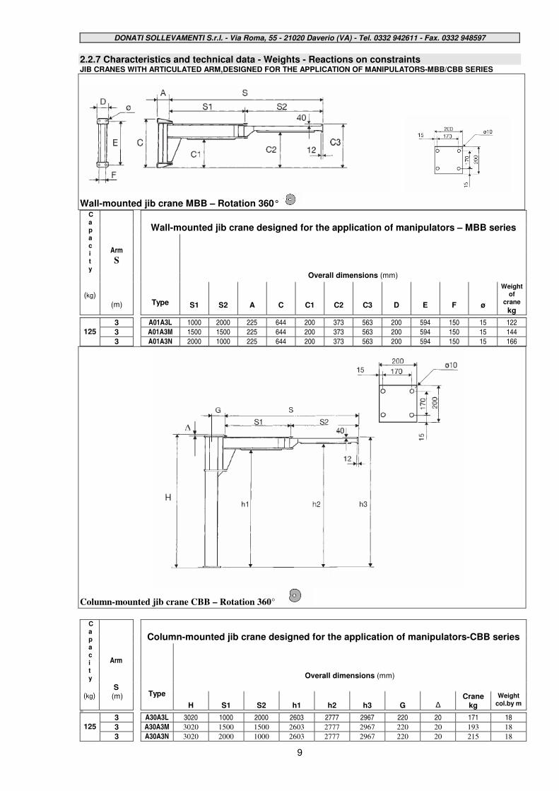
2.2.7 Characteristics and technical data - Weights - Reactions on constraints JIB CRANES WITH ARTICULATED ARM,DESIGNED FOR THE APPLICATION OF MANIPULATORS-MBB/CBB SERIES
Wall-mounted jib crane MBB – Rotation 360°
Wall-mounted jib crane designed for the application of manipulators – MBB series
Capacity
Overall dimensions (mm)
(kg)
Arm
S
(m)
Type
S1
S2
A
C
C1
C2
C3
D
E
F
ø
Weight of
crane kg
3 A01A3L 1000 2000 225 644 200 373 563 200 594 150 15 122
3 A01A3M 1500 1500 225 644 200 373 563 200 594 150 15 144
125
3
A01A3N 2000 1000 225 644 200 373 563 200 594 150 15 166
Column-mounted jib crane CBB – Rotation 360°
Column-mounted jib crane designed for the application of manipulators-CBB series
Capacity
Overall dimensions (mm)
(kg)
Arm
S (m)
Type H
S1
S2
h1
h2
h3
G
∆
Crane kg
Weight col.by m
200
3 A30A3L 3020 1000 2000 2603 2777 2967 220 20 171 18
3 A30A3M 3020 1500 1500 2603 2777 2967 220 20 193 18
125
3
A30A3N 3020 2000 1000 2603 2777 2967 220 20 215 18

DONATI SOLLEVAMENTI S.r.l. - Via Roma, 55 - 21020 Daverio (VA) - Tel. 0332 942611 - Fax. 0332 948597
10
WALL-MOUNTED JIB CRANES WITH ARTICULATED ARM,WITH FIXED HOIST – MBB SERIES
Wall-mounted jib crane – Rotation 360°
Wall-mounted jib crane with articulated arm with fixed hoist – MBB series
Overall dimensions (mm)
Capacity Arm
S
Added hoist
Weight of
crane
kg m
Size of jib crane
Type S1 S2 A C C1 C2 C3 D E F ∅∅∅∅ M
DMK Height I kg
A01A3A 1000 2000 225 644 200 373 591 200 594 150 15 180 1 285 114
A01A3B 1500 1500 225 644 200 373 591 200 594 150 15 180 1 285 138
3 A
A01A3C 2000 1000 225 644 200 373 591 200 594 150 15 180 1 285 160
A01B4A 1000 3000 225 644 200 333 591 200 594 150 15 180 1 285 141
A01B4B 1500 2500 225 644 200 333 591 200 594 150 15 180 1 285 163
4 B
A01B4C 2000 2000 225 644 200 373 591 200 594 150 15 180 1 285 171
A01B5A 2000 3000 225 644 200 333 591 200 594 150 15 180 1 285 198
A01B5B 2500 2500 225 644 200 333 591 200 594 150 15 180 1 285 220
5 B
A01B5C 3000 2000 225 644 200 373 591 200 594 150 15 180 1 285 230
A02C6B 2500 3500 280 930 455 592 850 250 870 190 22 180 1 285 326 6 C
A02C6C 3000 3000 280 930 455 592 850 250 870 190 22 180 1 285 361
A02C7A 3000 4000 280 930 455 572 850 250 870 190 22 180 1 285 389
125
7 C
A02C7B 3500 3500 280 930 455 592 850 250 870 190 22 180 1 285 410
A01B3A 1000 2000 225 644 200 333 591 200 594 150 15 180 1 - 2 285 - 318 124 3 B
A01B3B 1500 1500 225 644 200 333 591 200 594 150 15 180 1 - 2 285 - 318 145
A02C4A 1000 3000 280 930 455 552 850 250 870 190 22 180 1 - 2 285 - 318 218 4 C
A02C4C 2000 2000 280 930 455 592 850 250 870 190 22 180 1 - 2 285 - 318 258
A02C5A 2000 3000 280 930 455 552 850 250 870 190 22 180 1 - 2 285 - 318 295 5 C
A02C5B 2500 2500 280 930 455 552 850 250 870 190 22 180 1 - 2 285 - 318 324
A02D6B 2500 3500 280 930 455 552 850 250 870 190 22 180 1 - 2 285 - 318 348 6 D
A02D6C 3000 3000 280 930 455 552 850 250 870 190 22 180 1 - 2 285 - 318 380
A02D7A 3000 4000 280 930 455 552 850 250 870 190 22 180 1 - 2 285 - 318 405
250
7 D
A02D7B 3500 3500 280 930 455 552 850 250 870 190 22 180 1 - 2 285 - 318 432
A02C3A 1000 2000 280 930 455 592 850 250 870 190 22 180 2 318 182
A02C3F 1000 2000 280 930 455 592 850 250 870 190 22 190 3 385 182
A02C3B 1500 1500 280 930 455 592 850 250 870 190 22 180 2 318 215
3 C
A02C3G 1500 1500 280 930 455 592 850 250 870 190 22 190 3 385 215
A02D4A 1000 3000 280 930 455 552 850 250 870 190 22 180 2 318 218
A02D4F 1000 3000 280 930 455 552 850 250 870 190 22 190 3 385 218
A02D4C 2000 2000 280 930 455 592 850 250 870 190 22 180 2 318 258
4 D
A02D4H 2000 2000 280 930 455 592 850 250 870 190 22 190 3 385 258
A02D5A 2000 3000 280 930 455 552 850 250 870 190 22 180 2 318 295
A02D5F 2000 3000 280 930 455 552 850 250 870 190 22 190 3 385 295
A02D5B 2500 2500 280 930 455 552 850 250 870 190 22 180 2 318 324
5 D
A02D5G 2500 2500 280 930 455 552 850 250 870 190 22 190 3 385 324
A03E6A 2000 4000 315 1240 725 780 1118 300 1160 220 34 180 2 318 518
A03E6F 2000 4000 315 1240 725 780 1118 300 1160 220 34 190 3 385 518
A03E6C 3000 3000 315 1240 725 820 1118 300 1160 220 34 180 2 318 575
6 E
A03E6H 3000 3000 315 1240 725 820 1118 300 1160 220 34 190 3 385 575
A03E7A 3000 4000 315 1240 725 780 1118 300 1160 220 34 180 2 318 633
A03E7F 3000 4000 315 1240 725 780 1118 300 1160 220 34 190 3 385 633
A03E7B 3500 3500 315 1240 725 780 1118 300 1160 220 34 180 2 318 683
500
7 E
A03E7G 3500 3500 315 1240 725 780 1118 300 1160 220 34 190 3 385 683
DONATI SOLLEVAMENTI S.r.l. - Via Roma, 55 - 21020 Daverio (VA) - Tel. 0332 942611 - Fax. 0332 948597
11
COLUMN-MOUNTED JIB CRANES WITH ARTICULATED ARM,WITH FIXED HOIST – CBB SERIES
Column-mounted jib crane – Rotation 360°
Column-mounted jib crane with articulated arm with fixed hoist – CBB series
Height Overall dimensions (mm) Weight
Capacity
Arm S
H
Under beam
Added hoist
Crane
Col. by m
kg m
Size of jib crane
mm
Type
h1 h2
h3
S1
S2
G
M
∆ DMK I kg kg
3020 A30A3A 2603 2777 2995 1000 2000 220 180 32 1 285 163 18
3020 A30A3B 2603 2777 2995 1500 1500 220 180 32 1 285 187 18
3 A
3020 A30A3C 2603 2777 2995 2000 1000 220 180 32 1 285 209 18
3020 A30B4A 2603 2737 2995 1000 3000 255 180 32 1 285 222 28
3020 A30B4B 2603 2737 2995 1500 2500 255 180 32 1 285 244 28
4 B
3020 A30B4C 2603 2777 2995 2000 2000 255 180 32 1 285 252 28
3020 A30B5A 2603 2737 2995 2000 3000 255 180 32 1 285 279 28
3020 A30B5B 2603 2737 2995 2500 2500 255 180 32 1 285 301 28
5 B
3020 A30B5C 2603 2777 2995 3000 2000 255 180 32 1 285 311 28
3525 A35C6B 3083 3220 3478 2500 3500 310 180 47 1 285 443 34 6 C
3525 A35C6C 3083 3220 3478 3000 3000 310 180 47 1 285 478 34
3525 A35C7A 3083 3200 3478 3000 4000 310 180 47 1 285 506 34
125
7 C
3525 A35C7B 3083 3220 3478 3500 3500 310 180 47 1 285 527 34
3020 A30B3A 2603 2737 2995 1000 2000 255 180 32 1 - 2 285 - 318 205 28 3 B
3020 A30B3B 2603 2737 2995 1500 1500 255 180 32 1 - 2 285 - 318 226 28
3525 A35C4A 3083 3180 3478 1000 3000 310 180 42 1 - 2 285 - 318 335 34 4 C
3525 A35C4C 3083 3220 3478 2000 2000 310 180 42 1 - 2 285 - 318 375 34
3525 A35C5A 3083 3180 3478 2000 3000 310 180 42 1 - 2 285 - 318 412 34 5 C
3525 A35C5B 3083 3180 3478 2500 2500 310 180 42 1 - 2 285 - 318 441 34
3525 A35D6B 3083 3180 3478 2500 3500 360 180 42 1 - 2 285 - 318 525 51 6 D
3525 A35D6C 3083 3180 3478 3000 3000 360 180 42 1 - 2 285 - 318 557 51
3525 A35D7A 3083 3180 3478 3000 4000 360 180 42 1 - 2 285 - 318 582 51
250
7 D
3525 A35D7B 3083 3180 3478 3500 3500 360 180 42 1 - 2 285 - 318 609 51
3525 A35C3A 3083 3220 3478 1000 2000 310 180 42 2 318 299 34
3525 A35C3F 3083 3220 3478 1000 2000 310 190 42 3 385 299 34
3525 A35C3B 3083 3220 3478 1500 1500 310 180 42 2 318 332 34
3 C
3525 A35C3G 3083 3220 3478 1500 1500 310 190 42 3 385 332 34
3525 A35D4A 3083 3180 3478 1000 3000 360 180 42 2 318 395 51
3525 A35D4F 3083 3180 3478 1000 3000 360 190 42 3 385 395 51
3525 A35D4C 3083 3220 3478 2000 2000 360 180 42 2 318 435 51
4 D
3525 A35D4H 3083 3220 3478 2000 2000 360 190 42 3 385 435 51
3525 A35D5A 3083 3180 3478 2000 3000 360 180 42 2 318 472 51
3525 A35D5F 3083 3180 3478 2000 3000 360 190 42 3 385 472 51
3525 A35D5B 3083 3180 3478 2500 2500 360 180 42 2 318 501 51
5 D
3525 A35D5G 3083 3180 3478 2500 2500 360 190 42 3 385 501 51
4025 A40E6A 3565 3620 3958 2000 4000 415 180 45 2 318 805 73
4025 A40E6F 3565 3620 3958 2000 4000 415 190 45 3 385 805 73
4025 A40E6C 3565 3660 3958 3000 3000 415 180 45 2 318 862 73
6 E
4025 A40E6H 3565 3660 3958 3000 3000 415 190 45 3 385 862 73
4025 A40E7A 3565 3620 3958 3000 4000 415 180 45 2 318 920 73
4025 A40E7F 3565 3620 3958 3000 4000 415 190 45 3 385 920 73
4025 A40E7B 3565 3620 3958 3500 3500 415 180 45 2 318 970 73
500
7 E
4025 A40E7G 3565 3620 3958 3500 3500 415 190 45 3 385 970 73
DONATI SOLLEVAMENTI S.r.l. - Via Roma, 55 - 21020 Daverio (VA) - Tel. 0332 942611 - Fax. 0332 948597
12
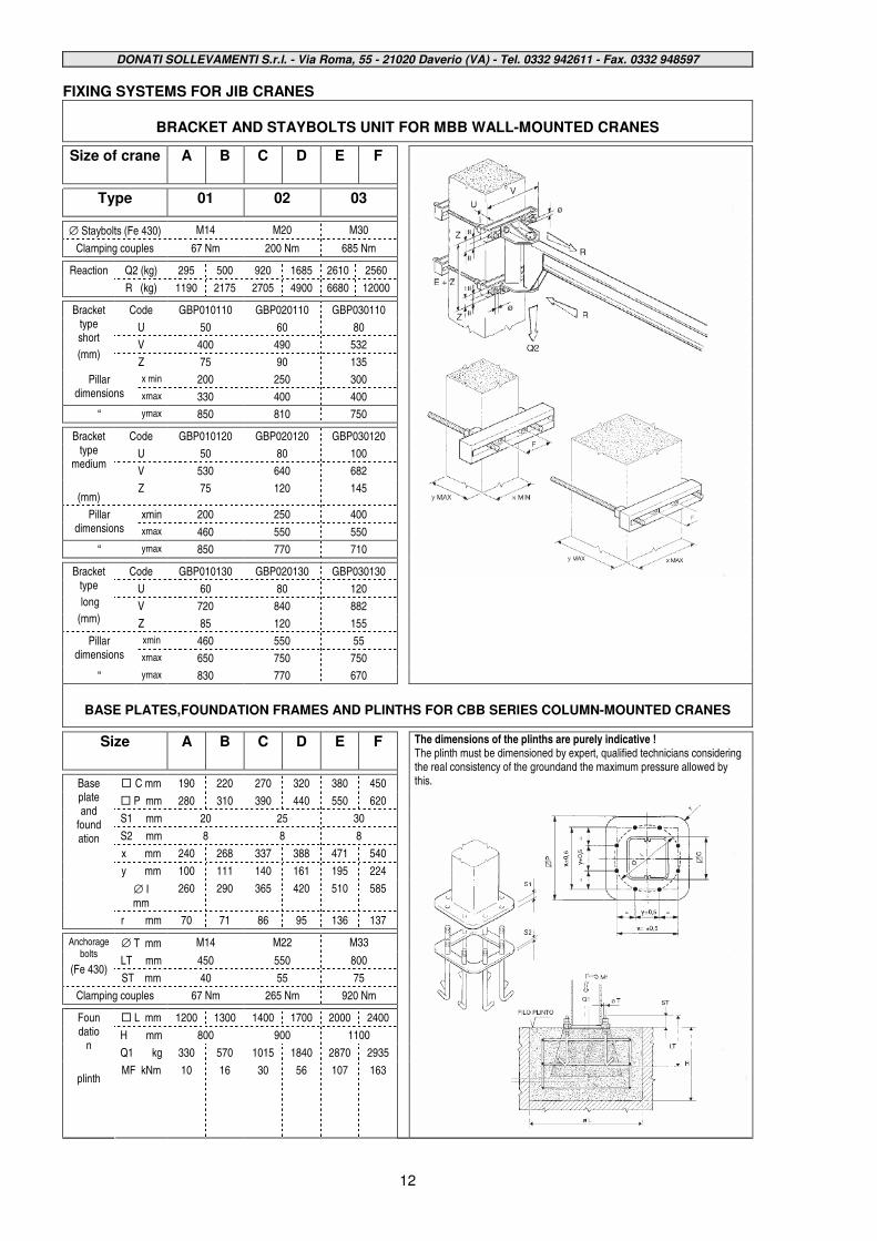
FIXING SYSTEMS FOR JIB CRANES
BRACKET AND STAYBOLTS UNIT FOR MBB WALL-MOUNTED CRANES
Size of crane A B C D E F
Type 01 02 03
∅ Staybolts (Fe 430) M14 M20 M30
Clamping couples 67 Nm 200 Nm 685 Nm
Q2 (kg) 295 500 920 1685 2610 2560 Reaction
R (kg) 1190 2175 2705 4900 6680 12000
Code GBP010110 GBP020110 GBP030110
U 50 60 80
V 400 490 532
Bracket type short
(mm) Z 75 90 135
x min 200 250 300 Pillar dimensions xmax 330 400 400
“ ymax 850 810 750
Code GBP010120 GBP020120 GBP030120
U 50 80 100
V 530 640 682
Bracket type
medium
(mm) Z 75 120 145
xmin 200 250 400 Pillar dimensions xmax 460 550 550
“ ymax 850 770 710
Code GBP010130 GBP020130 GBP030130
U 60 80 120
V 720 840 882
Bracket type
long
(mm) Z 85 120 155
xmin 460 550 55 Pillar dimensions xmax 650 750 750
“ ymax 830 770 670
BASE PLATES,FOUNDATION FRAMES AND PLINTHS FOR CBB SERIES COLUMN-MOUNTED CRANES
Size A B C D E F
� C mm 190 220 270 320 380 450
� P mm 280 310 390 440 550 620
S1 mm 20 25 30
S2 mm 8 8 8
x mm 240 268 337 388 471 540
y mm 100 111 140 161 195 224
∅ I mm
260 290 365 420 510 585
Base plate and
foundation
r mm 70 71 86 95 136 137
∅ T mm M14 M22 M33
LT mm 450 550 800
Anchorage bolts
(Fe 430) ST mm 40 55 75
Clamping couples 67 Nm 265 Nm 920 Nm
� L mm 1200 1300 1400 1700 2000 2400
H mm 800 900 1100
Q1 kg 330 570 1015 1840 2870 2935
Foundatio
n
plinth MF kNm 10 16 30 56 107 163
The dimensions of the plinths are purely indicative ! The plinth must be dimensioned by expert, qualified technicians considering the real consistency of the groundand the maximum pressure allowed by this.
DONATI SOLLEVAMENTI S.r.l. - Via Roma, 55 - 21020 Daverio (VA) - Tel. 0332 942611 - Fax. 0332 948597
13
3. - SAFETY AND ACCIDENT PREVENTION § The manually rotated jib cranes with articulated arm, series CBB column-mounted and wall-mounted
series MBB and accessories have been designed and manufactured using the most modern technical
knowledge and can be used safely. § The dangers for persons working with them can be totally eliminated and/or notably reduced only if the
jib crane is used by authorised staff who are appropriately trained and sufficiently prepared in accordance
with the instructions in this documentation.
THE STAFF ARE RESPONSIBLE FOR THE FOLLOWING OPERATIONS:
§ Completing the jib crane with any missing parts and installing it (e.g. hoist, electric controls, fixing
accessories, etc.) § Setting up the crane and, in any case, the managing of its functioning;
§ Inspections and checks of the crane and its components, before starting up the machine, during its
functioning or also after it stops. § Maintenance of the crane, the checking and the repair and/or replacement of its components.
§ Staff must be completely informed about the potential dangers in the execution of their duties, both
regarding the functioning and the correct use of safety measures available on the machine. § These staff must, moreover follow the safety regulations carefully, as described in this chapter, to
prevent dangerous situations occurring.
3.1 Qualifications of qualified operators
§ The following table is designed to define more clearly the field of intervention and the consequent
assumption of responsibility of every single OPERATOR, given their specific training and qualification
obtained. It shows with a pictogram the professional figures necessary for every kind of intervention.
PICTOGRAM
OPERATOR PROFILE
OPERATOR
Jib crane operator: Persons qualified to perform simple tasks, that is the driving of the crane by use of the controls and the loading and unloading of the materials to
OPERATOR be moved.
MECHANICAL MAINTENANCE
OFFICER
Mechanical maintenance officer: Qualified persons able to intervene on the crane in normal conditions, to carry out normal adjustments to the mechanisms, ordinary maintenance
checks and mechanical repairs.
ELECTRICAL MAINTENANCE
OFFICER
Electrical maintenance officer: Qualified persons able to intervene on the crane in normal conditions and for normal interventions of an electrical nature, adjustments, maintenance and repairs. This person can operate with the presence
of current in the control boards.
MECHANICAL TECHNICIAN
Mechanical technician: Qualified technician authorised to carry out operations of a complex and
exceptional mechanical nature.
ELECTRICAL TECHNICIAN
Electrical technician: Qualified technician authorised to carry out operations of a complex and
exceptional electrical nature.
DONATI SOLLEVAMENTI S.r.l. - Via Roma, 55 - 21020 Daverio (VA) - Tel. 0332 942611 - Fax. 0332 948597
14
3.2 General safety regulations § Before putting the jib crane into service it is necessary:
• to read the technical documentation carefully;
• to find out about the functioning and the positioning of the emergency stopping devices;
• to know which safety devices are installed on the jib crane and where they are positioned; § Some activities to be carried out on functioning components (e.g. replacing a hoist chain) expose the
operators to situations of grave danger, so it is necessary to adhere strictly to the following rules:
• Staff must be authorised and properly trained regarding the operating procedures to follow, the
dangerous situations that could occur and the correct methods for preventing them.
• If ,exceptionally, staff have to disactivate completely or partially, open or remove the protective
covers to allow a particular specialised technical intervention of maintenance, inspection or repair to
be carried out, it will be their precise duty to put back immediately the relevant protective covers at the
end of the intervention. The staff in charge must make sure that at the end of the intervention
mechanical parts, tools or other devices used are not forgotten on the crane, since this may provoke
damages or malfunctions.
• Staff in charge of maintenance, inspection and repair operations must use all the necessary and
possible preventive safety measures before beginning work for their own safety, and in particular, they
must check that:
• The jib crane is disactivated and the appropriate preventive measures have been taken (signs,
blocking controls etc.) to avoid the accidental starting. To allow the execution of a technical
intervention on an electric device, in the presence of voltage current, pay the maximum attention and
operate with extreme caution..
3.3 Safety symbols § In the manual and in danger zones, signs and pictograms are used to underline or bring attention to
potentially dangerous situations due to residual risks, or to actions which must be performed obligatorily
according to the safety procedures shown in this manual.
SIGNS USED TO INDICATE DANGERS SIGN MEANING
DANGER PARTS WITH LIVE TENSION
Signals the presence of live voltage and is fixed to electrical
equipment and on any structure which has live electrical voltage inside.
GENERAL DANGER
Warning: general danger (accompanied by diagram which indicates what kind of danger)
DANGER OF CRUSHING
Warning danger of crushing due to mechanical machine-parts
in movement.
DANGER OF ENTANGLEMENT
Warning danger of entanglement or dragging from machine-parts in motion (chains, wheels, etc.)
DANGER FROM SUSPENDED LOADS
Warning danger from suspended loads being moved by the crane.
DONATI SOLLEVAMENTI S.r.l. - Via Roma, 55 - 21020 Daverio (VA) - Tel. 0332 942611 - Fax. 0332 948597
15
SIGNS USED TO INDICATE BANS
SIGN MEANING
IT IS FORBIDDEN TO REMOVE THE PROTECTION
It is forbidden to remove the safety devices on a machine in motion.
IT IS FORBIDDEN TO MANOEUVRE
It is forbidden to carry out manoeuvres during maintenance
phases of moving machine-parts.
SIGNS USED TO INDICATE OBLIGATIONS
SIGN MEANING
CONSULT THE MANUAL
Consult the manual when you see, preceding or positioned
inside an indication (instructions, settings, maintenance, etc.)
GLOVES MUST BE WORN
It is compulsory to wear protection gloves.
HELMETS MUST BE WORN
It is compulsory to wear safety helmets.
PROTECTIVE FOOTWEAR MUST BE WORN
It is compulsory to wear non-slip protective footwear.
SAFETY HARNESSES MUST BE WORN
It is compulsory to wear safety harnesses in operations at a
height with the risk of falling down.
CHECK LIFTING OF THE MACHINE-PARTS
The preventive checking of wire ropes, hooks, safety harnesses and accessories used for lifting and manoeuvring
is compulsory.
SIGNS USED FOR SAFETY INDICATIONS
SIGN MEANING
AUXILIARY ILLUMINATION
For the interventions indicated the use of auxiliary
illumination is recommended.
DONATI SOLLEVAMENTI S.r.l. - Via Roma, 55 - 21020 Daverio (VA) - Tel. 0332 942611 - Fax. 0332 948597
16
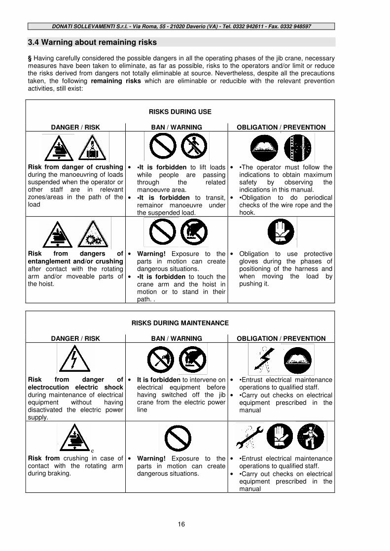
3.4 Warning about remaining risks § Having carefully considered the possible dangers in all the operating phases of the jib crane, necessary measures have been taken to eliminate, as far as possible, risks to the operators and/or limit or reduce the risks derived from dangers not totally eliminable at source. Nevertheless, despite all the precautions taken, the following remaining risks which are eliminable or reducible with the relevant prevention activities, still exist:
RISKS DURING USE
DANGER / RISK BAN / WARNING OBLIGATION / PREVENTION
Risk from danger of crushing during the manoeuvring of loads suspended when the operator or other staff are in relevant zones/areas in the path of the load
• •It is forbidden to lift loads while people are passing through the related manoeuvre area.
• •It is forbidden to transit, remainor manoeuvre under the suspended load.
• •The operator must follow the indications to obtain maximum safety by observing the indications in this manual.
• •Obligation to do periodical checks of the wire rope and the hook.
Risk from dangers of entanglement and/or crushing after contact with the rotating arm and/or moveable parts of the hoist.
• Warning! Exposure to the parts in motion can create dangerous situations.
• •It is forbidden to touch the crane arm and the hoist in motion or to stand in their path. .
• Obligation to use protective gloves during the phases of positioning of the harness and when moving the load by pushing it.
RISKS DURING MAINTENANCE
DANGER / RISK BAN / WARNING OBLIGATION / PREVENTION
Risk from danger of electrocution electric shock during maintenance of electrical equipment without having disactivated the electric power supply.
• It is forbidden to intervene on electrical equipment before having switched off the jib crane from the electric power line
• •Entrust electrical maintenance operations to qualified staff.
• •Carry out checks on electrical equipment prescribed in the manual
e
Risk from crushing in case of contact with the rotating arm during braking.
• Warning! Exposure to the parts in motion can create dangerous situations.
• •Entrust electrical maintenance operations to qualified staff.
• •Carry out checks on electrical equipment prescribed in the manual
DONATI SOLLEVAMENTI S.r.l. - Via Roma, 55 - 21020 Daverio (VA) - Tel. 0332 942611 - Fax. 0332 948597
17
3.5 Safety measures and instructions 3.5.1 Control devices § The manually rotated jib cranes with articulated arm, in the CBB column-mounted version and the MBB wall-mounted version can be controlled in the following ways: 1 If fitted with an electric hoist the movements are activated:
*by a push-button panel with ascent and descent buttons to control the lifting movement.
2 If fitted with a manual hoist the movements are activated:
*by mechanical working of the chain of the hoist for the lifting movement.
3 In all cases the rotation movement of the jib crane arm, both in a clockwise and anti-clockwise direction, is activated manually, with a pushing flexing of the load. 3.5.2 Safety and emergency devices § The manually rotated jib cranes with articulated arm in the CBB column-mounted version and the MBB wall-mounted version, are fitted with the following safety and emergency devices: 1. Rotating brake, by friction, which allows the regulation of the arm’s rotating force and ensures the
stability of positioning. 2. Anti-collision device, available on request, to avoid the telescoping of two or more arms which,
operating in the same area, can interfere with each other; or to avoid the collision of the arm with surrounding structures.

DONATI SOLLEVAMENTI S.r.l. - Via Roma, 55 - 21020 Daverio (VA) - Tel. 0332 942611 - Fax. 0332 948597
18
3.5.3 Warning and signalling devices - List of labels § The manually rotated jib cranes with articulated arm, column-mounted series CBB and wall-mounted series MBB, are fitted with the following devices:
• Labels on the machine:
• logotype of the manufacturer: • label of jib crane data with the CE marque when foreseen (*)
• label indicating the maximum lifting capacity of the jib crane
• warning labels about remaining risks
• labels of the hoist
fig.7
§ Legibility and conservation of the labels The labels and the data written on them must always be kept legible and must be periodically cleaned. If a label deteriorates and/or is no longer legible, even only in one of the shown elements, then we recommend requesting another from the manufacturer, quoting the data contained in this manual or on the original label, and providing for its replacement.
(*) When the jib crane is supplied without lifting unit (hoistr) the data label of the crane (fig 7) does not carry the CE marque.
The labels must not be removed and it is absolutely forbidden to put other labels on the crane without previous authorization by DONATI SOLLEVAMENTI S.r.l.
DONATI SOLLEVAMENTI S.r.l. - Via Roma, 55 - 21020 Daverio (VA) - Tel. 0332 942611 - Fax. 0332 948597
19
4. - HANDLING - INSTALLATION - PUTTING INTO OPERATION
4.1 - General notes at delivery
•••• The manually rotated jib cranes of the CBB column-mounted version and the MBB wall-mounted version, are delivered not assembled, in their main parts which are the column or bracket, the arm, the electric system and, when part of the supply, the lifting unit.
•••• The user must therefore proceed to the phases of installation of the jib crane following the instructions contained in this chapter and assigning if possible the assembly to specialised installers.
•••• The operations described in this chapter, because of their delicacy and importance, can cause, if badly performed, grave safety risks in particular for persons exposed during the installation and use phases of the jib crane.
•••• In any case, the operations must be carried out by professionally qualified staff who specialise in industrial construction installing, with knowledge in electromechanics, equipped with work equipment and personal protection conforming to the current safety and accident prevention legislation in the workplace, and who have first read carefully this publication.
On receiving the supplied goods check and ensure that :
•••• The despatch data (receiver’s address n° of items, n° of order, etc.) correspond to the accompanying documentation (transport documents and/or related packing-list).
•••• Technical/legal documentation which comes with the jib crane includes (fig 8):
•••• The instruction manual for the use of the crane to be installed.
•••• The CE declaration of Conformity or, alternatively, the Manufacturer’s Declaration.
•••• The control register, when provided.
•••• The instructions for the use of the hoist/trolley to be installed on the crane, if included in the supply.
•••• The packing, if it is part of the supply, is in good condition, in one piece and free from damage.
In case of damage or missing parts tell the courier, note it on the accompanying document and notify DONATI SOLLEVAMENTI S.r.l. within eight days of receiving the goods.
fig.8
DONATI SOLLEVAMENTI S.r.l. - Via Roma, 55 - 21020 Daverio (VA) - Tel. 0332 942611 - Fax. 0332 948597
20
4.2 Packing, transportation and handling
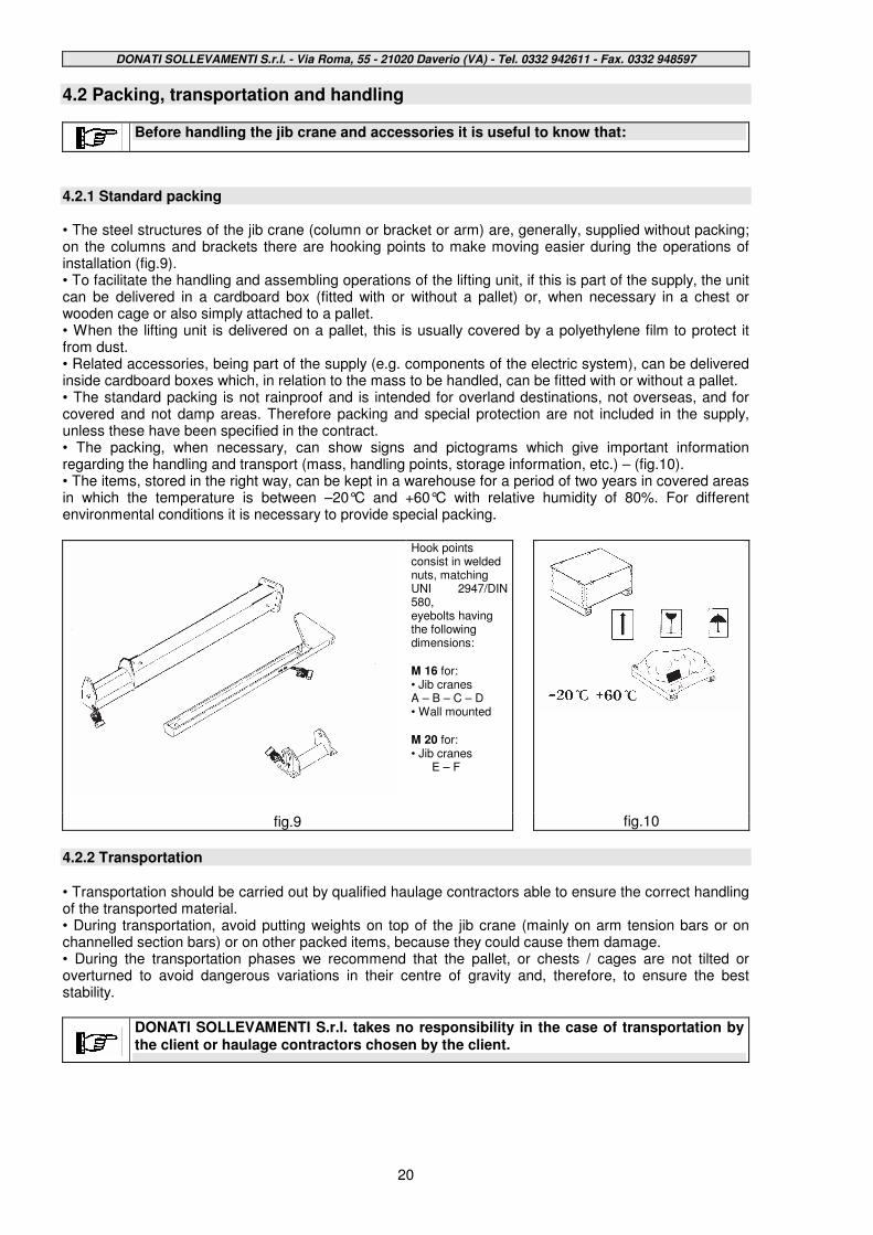
Before handling the jib crane and accessories it is useful to know that:
4.2.1 Standard packing • The steel structures of the jib crane (column or bracket or arm) are, generally, supplied without packing; on the columns and brackets there are hooking points to make moving easier during the operations of installation (fig.9). • To facilitate the handling and assembling operations of the lifting unit, if this is part of the supply, the unit can be delivered in a cardboard box (fitted with or without a pallet) or, when necessary in a chest or wooden cage or also simply attached to a pallet. • When the lifting unit is delivered on a pallet, this is usually covered by a polyethylene film to protect it from dust. • Related accessories, being part of the supply (e.g. components of the electric system), can be delivered inside cardboard boxes which, in relation to the mass to be handled, can be fitted with or without a pallet. • The standard packing is not rainproof and is intended for overland destinations, not overseas, and for covered and not damp areas. Therefore packing and special protection are not included in the supply, unless these have been specified in the contract. • The packing, when necessary, can show signs and pictograms which give important information regarding the handling and transport (mass, handling points, storage information, etc.) – (fig.10). • The items, stored in the right way, can be kept in a warehouse for a period of two years in covered areas in which the temperature is between –20°C and +60°C with relative humidity of 80%. For different environmental conditions it is necessary to provide special packing.
Hook points consist in welded nuts, matching UNI 2947/DIN 580, eyebolts having the following dimensions: M 16 for: • Jib cranes A – B – C – D • Wall mounted M 20 for: • Jib cranes
E – F
fig.9
fig.10
4.2.2 Transportation • Transportation should be carried out by qualified haulage contractors able to ensure the correct handling of the transported material. • During transportation, avoid putting weights on top of the jib crane (mainly on arm tension bars or on channelled section bars) or on other packed items, because they could cause them damage. • During the transportation phases we recommend that the pallet, or chests / cages are not tilted or overturned to avoid dangerous variations in their centre of gravity and, therefore, to ensure the best stability.
DONATI SOLLEVAMENTI S.r.l. takes no responsibility in the case of transportation by the client or haulage contractors chosen by the client.
DONATI SOLLEVAMENTI S.r.l. - Via Roma, 55 - 21020 Daverio (VA) - Tel. 0332 942611 - Fax. 0332 948597
21
4.2.3 Handling
For the handling of jib cranes proceed as follows :
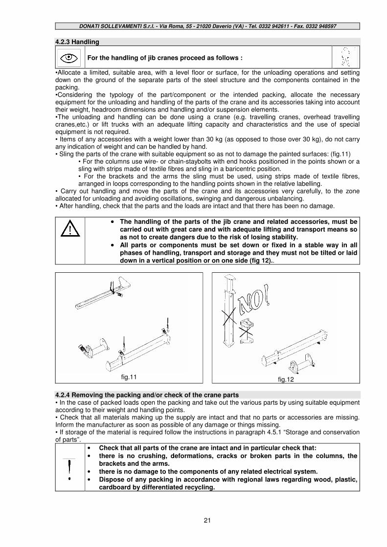
•Allocate a limited, suitable area, with a level floor or surface, for the unloading operations and setting down on the ground of the separate parts of the steel structure and the components contained in the packing. •Considering the typology of the part/component or the intended packing, allocate the necessary equipment for the unloading and handling of the parts of the crane and its accessories taking into account their weight, headroom dimensions and handling and/or suspension elements. •The unloading and handling can be done using a crane (e.g. travelling cranes, overhead travelling cranes,etc.) or lift trucks with an adequate lifting capacity and characteristics and the use of special equipment is not required. • Items of any accessories with a weight lower than 30 kg (as opposed to those over 30 kg), do not carry any indication of weight and can be handled by hand. • Sling the parts of the crane with suitable equipment so as not to damage the painted surfaces: (fig.11)
• For the columns use wire- or chain-staybolts with end hooks positioned in the points shown or a sling with strips made of textile fibres and sling in a baricentric position. • For the brackets and the arms the sling must be used, using strips made of textile fibres, arranged in loops corresponding to the handling points shown in the relative labelling.
• Carry out handling and move the parts of the crane and its accessories very carefully, to the zone allocated for unloading and avoiding oscillations, swinging and dangerous unbalancing. • After handling, check that the parts and the loads are intact and that there has been no damage.
•••• The handling of the parts of the jib crane and related accessories, must be carried out with great care and with adequate lifting and transport means so as not to create dangers due to the risk of losing stability.
•••• All parts or components must be set down or fixed in a stable way in all phases of handling, transport and storage and they must not be tilted or laid down in a vertical position or on one side (fig 12)..
fig.11
fig.12
4.2.4 Removing the packing and/or check of the crane parts • In the case of packed loads open the packing and take out the various parts by using suitable equipment according to their weight and handling points. • Check that all materials making up the supply are intact and that no parts or accessories are missing. Inform the manufacturer as soon as possible of any damage or things missing. • If storage of the material is required follow the instructions in paragraph 4.5.1 “Storage and conservation of parts”.
• Check that all parts of the crane are intact and in particular check that:
• there is no crushing, deformations, cracks or broken parts in the columns, the brackets and the arms.
• there is no damage to the components of any related electrical system.
• Dispose of any packing in accordance with regional laws regarding wood, plastic, cardboard by differentiated recycling.
DONATI SOLLEVAMENTI S.r.l. - Via Roma, 55 - 21020 Daverio (VA) - Tel. 0332 942611 - Fax. 0332 948597
22
4.3 - Installation of the jib crane 4.3.1 Duties and responsibilities of the installer
• The installation of the jib crane, for the size of its operations, can pose, if not carried out correctly, serious risks to the safety of people exposed both at the assembly stage and at the successive stage of use of the crane. Therefore, the installation must be assigned to installers specialising in the assembly of industrial equipment.
• The lifting operations and positioning at a height of the parts of the crane must be carried out by installers equipped with:
• adequate individual safety measures (e.g. helmet, gloves, safety harness, etc.)
• work equipment (e.g. forklift truck, scaffolding etc.) suitable for the purpose
• And following a careful evaluation of the following parameters:
• typology of the workplace, its environmental characteristics, (type of floor surface, etc.)
• height of the working space in relation to the loading surface
• dimensions and weight of the components to be installed
• available spaces for the handling of the parts to be installed.
Before assembling the parts and using the jib crane, the installer must check that the crane characteristics are suitable to what requested and for the foreseen use, in particular:
1. The lifting capacity of the crane is greater than/equal to the loads to be lifted. 2. The characteristics of the fixing structures (plinth, floor, wall, column,etc.) have been “declared
suitable” by the user or expert technicians employed by the user.
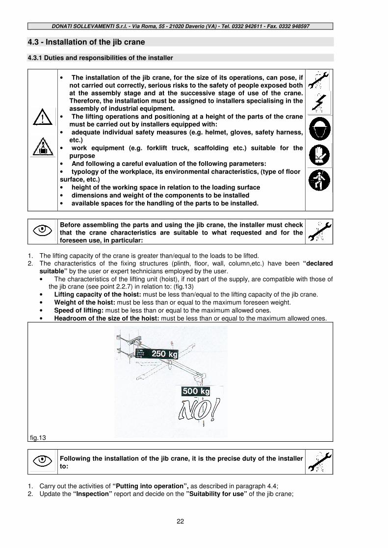
• The characteristics of the lifting unit (hoist), if not part of the supply, are compatible with those of the jib crane (see point 2.2.7) in relation to: (fig.13)
• Lifting capacity of the hoist: must be less than/equal to the lifting capacity of the jib crane.
• Weight of the hoist: must be less than or equal to the maximum foreseen weight.
• Speed of lifting: must be less than or equal to the maximum allowed ones.
• Headroom of the size of the hoist: must be less than or equal to the maximum allowed ones.
fig.13
Following the installation of the jib crane, it is the precise duty of the installer to:
1. Carry out the activities of “Putting into operation”, as described in paragraph 4.4; 2. Update the “Inspection” report and decide on the ”Suitability for use” of the jib crane;
DONATI SOLLEVAMENTI S.r.l. - Via Roma, 55 - 21020 Daverio (VA) - Tel. 0332 942611 - Fax. 0332 948597
23
4.3.2 Preparing the place of installation
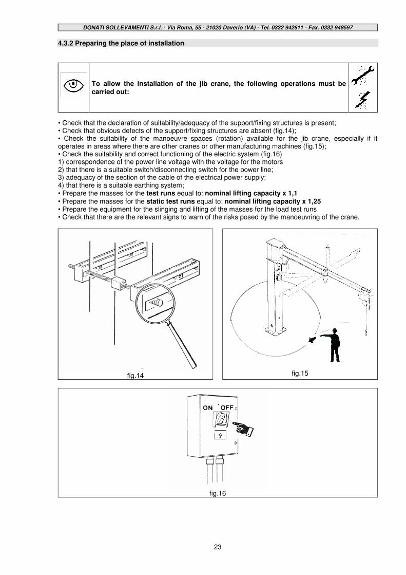
To allow the installation of the jib crane, the following operations must be carried out:
• Check that the declaration of suitability/adequacy of the support/fixing structures is present; • Check that obvious defects of the support/fixing structures are absent (fig.14); • Check the suitability of the manoeuvre spaces (rotation) available for the jib crane, especially if it operates in areas where there are other cranes or other manufacturing machines (fig.15); • Check the suitability and correct functioning of the electric system (fig.16) 1) correspondence of the power line voltage with the voltage for the motors 2) that there is a suitable switch/disconnecting switch for the power line; 3) adequacy of the section of the cable of the electrical power supply; 4) that there is a suitable earthing system; • Prepare the masses for the test runs equal to: nominal lifting capacity x 1,1 • Prepare the masses for the static test runs equal to: nominal lifting capacity x 1,25 • Prepare the equipment for the slinging and lifting of the masses for the load test runs • Check that there are the relevant signs to warn of the risks posed by the manoeuvring of the crane.
fig.14
fig.15
fig.16
DONATI SOLLEVAMENTI S.r.l. - Via Roma, 55 - 21020 Daverio (VA) - Tel. 0332 942611 - Fax. 0332 948597
24
4.3.3 Assembly of the column – For CBB column-mounted cranes
• The fixing of the column to the ground can be done in the following ways:
• using a foundation frame with log bolts sunk into a plinth made of reinforced concrete
• using bolts and screw anchors or dowelling.
•••• The fixing of the column using bolts and screw anchors or dowelling requires a scrupulous check of suitability in relation to the type of support flooring.
•••• The technical data, so that the user can choose the right size for the the foundation plinth, are shown in the table in paragraph 2.2.7 (“Fixing systems”p.12).The plinth size must be in relation to the real consistency of the ground and the specific maximum pressure that it can bear.
•••• The suitability checks of the foundation are the responsibility of the user and must be carried out by technical experts who judge the feasibility and take responsibility for this.
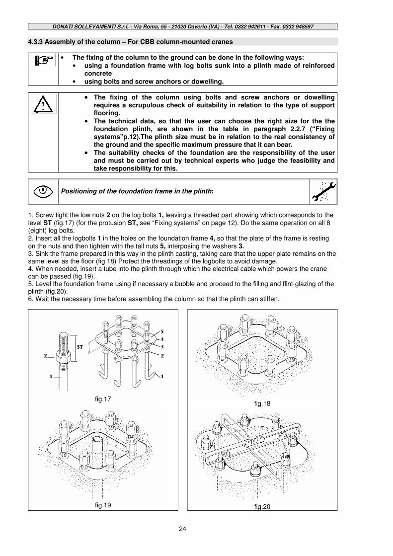
Positioning of the foundation frame in the plinth:
1. Screw tight the low nuts 2 on the log bolts 1, leaving a threaded part showing which corresponds to the level ST (fig.17) (for the protusion ST, see “Fixing systems” on page 12). Do the same operation on all 8 (eight) log bolts. 2. Insert all the logbolts 1 in the holes on the foundation frame 4, so that the plate of the frame is resting on the nuts and then tighten with the tall nuts 5, interposing the washers 3. 3. Sink the frame prepared in this way in the plinth casting, taking care that the upper plate remains on the same level as the floor (fig.18) Protect the threadings of the logbolts to avoid damage. 4. When needed, insert a tube into the plinth through which the electrical cable which powers the crane can be passed (fig.19). 5. Level the foundation frame using if necessary a bubble and proceed to the filling and flint-glazing of the plinth (fig.20). 6. Wait the necessary time before assembling the column so that the plinth can stiffen.
fig.17
fig.18
fig.19
fig.20
DONATI SOLLEVAMENTI S.r.l. - Via Roma, 55 - 21020 Daverio (VA) - Tel. 0332 942611 - Fax. 0332 948597
25
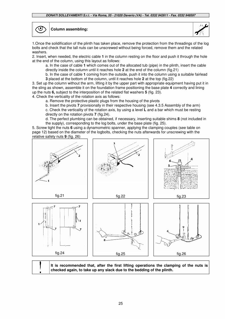
Column assembling:
1.Once the solidification of the plinth has taken place, remove the protection from the threadings of the log bolts and check that the tall nuts can be unscrewed without being forced, remove them and the related washers. 2. Insert, when needed, the electric cable 1 in the column resting on the floor and push it through the hole at the end of the column, using this layout as follows:
a. In the case of cable 1 which comes out of the allocated tub (pipe) in the plinth, insert the cable directly inside the column until it reaches hole 2 at the end of the column (fig.21) b. In the case of cable 1 coming from the outside, push it into the column using a suitable fairlead 3 placed at the bottom of the column, until it reaches hole 2 at the top (fig.22)
3. Set up the column without the arm, lifting it by the upper part with appropriate equipment having put it in the sling as shown, assemble it on the foundation frame positioning the base plate 4 correctly and lining up the nuts 6, subject to the interposition of the related flat washers 5 (fig. 23). 4. Check the verticality of the rotation axis as follows:
a. Remove the protective plastic plugs from the housing of the pivots b. Insert the pivots 7 provisionally in their respective housing (see 4.3.5 Assembly of the arm) c. Check the verticality of the rotation axis, by using a level L and a bar which must be resting directly on the rotation pivots 7 (fig.24). d. The perfect plumbing can be obtained, if necessary, inserting suitable shims 8 (not included in the supply), corresponding to the log bolts, under the base plate (fig. 25).
5. Screw tight the nuts 6 using a dynamometric spanner, applying the clamping couples (see table on page 12) based on the diameter of the logbolts, checking the nuts afterwards for unscrewing with the relative safety nuts 9 (fig. 26)
fig.21
fig.22
fig.23
fig.24
fig.25
fig.26
It is recommended that, after the first lifting operations the clamping of the nuts is checked again, to take up any slack due to the bedding of the plinth.
DONATI SOLLEVAMENTI S.r.l. - Via Roma, 55 - 21020 Daverio (VA) - Tel. 0332 942611 - Fax. 0332 948597
26
4.3.4 Assembly of the bracket – For MBB wall-mounted cranes
• The fixing of the bracket to the support structure can take place as follows:
• using brackets with the related staybolts
• using bolts and screw anchors or dowelling.
•••• The fixing of the bracket using bolts and screw anchors or dowelling, requires a scrupulous check of suitability in relation to the type of support.
•••• Technical data, so that the user can scale the fixings to the right size are shown in the table at paragraph 2.2.7 (“Fixing systems”-page 12).
•••• The suitability checks of the support structure are the responsibility of the user and must be carried out by expert technicians who evaluate the feasibility and take on the related responsibilities.
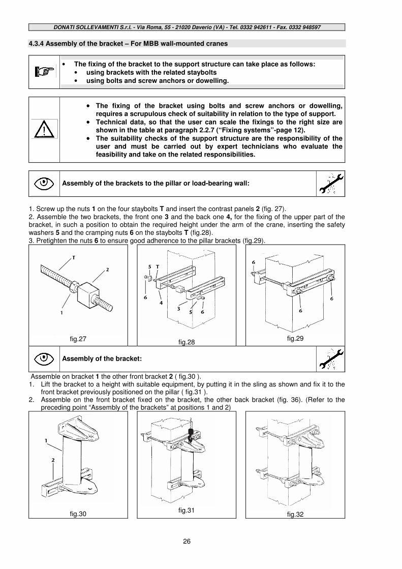
Assembly of the brackets to the pillar or load-bearing wall:
1. Screw up the nuts 1 on the four staybolts T and insert the contrast panels 2 (fig. 27). 2. Assemble the two brackets, the front one 3 and the back one 4, for the fixing of the upper part of the bracket, in such a position to obtain the required height under the arm of the crane, inserting the safety washers 5 and the cramping nuts 6 on the staybolts T (fig.28). 3. Pretighten the nuts 6 to ensure good adherence to the pillar brackets (fig.29).
fig.27
fig.28
fig.29
Assembly of the bracket:
Assemble on bracket 1 the other front bracket 2 ( fig.30 ). 1. Lift the bracket to a height with suitable equipment, by putting it in the sling as shown and fix it to the
front bracket previously positioned on the pillar ( fig.31 ). 2. Assemble on the front bracket fixed on the bracket, the other back bracket (fig. 36). (Refer to the
preceding point “Assembly of the brackets” at positions 1 and 2)
fig.30
fig.31
fig.32
DONATI SOLLEVAMENTI S.r.l. - Via Roma, 55 - 21020 Daverio (VA) - Tel. 0332 942611 - Fax. 0332 948597
27
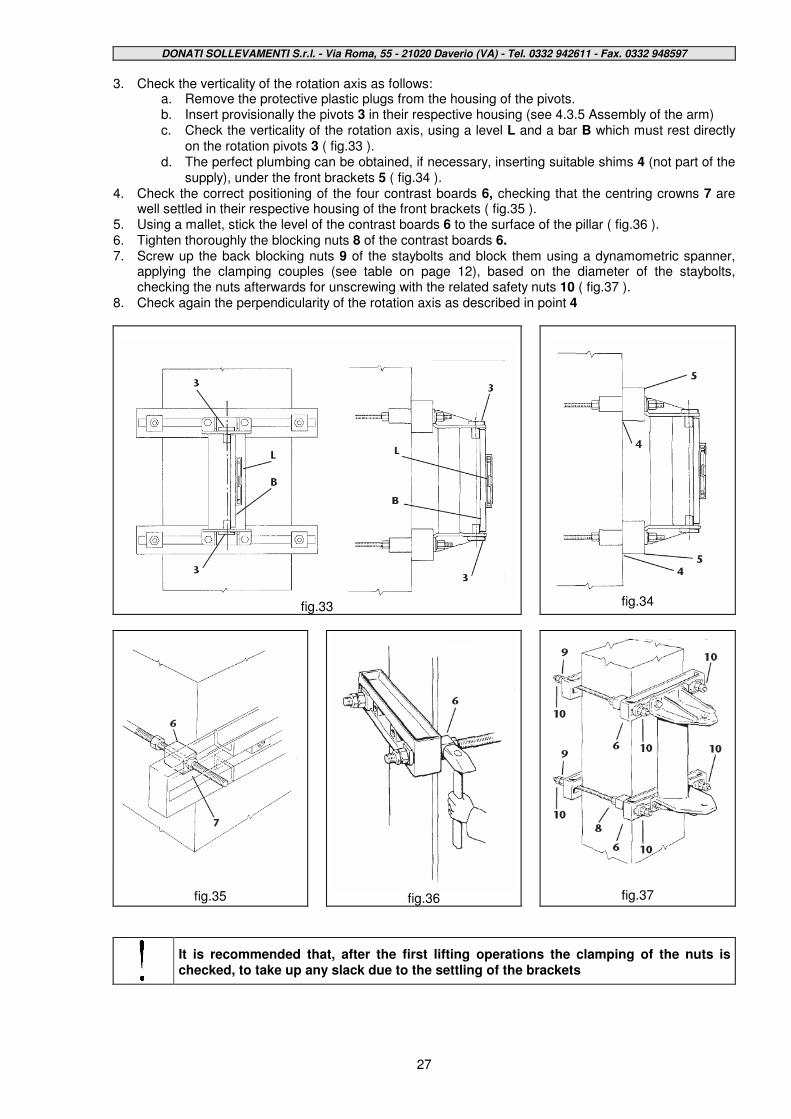
3. Check the verticality of the rotation axis as follows: a. Remove the protective plastic plugs from the housing of the pivots. b. Insert provisionally the pivots 3 in their respective housing (see 4.3.5 Assembly of the arm) c. Check the verticality of the rotation axis, using a level L and a bar B which must rest directly
on the rotation pivots 3 ( fig.33 ). d. The perfect plumbing can be obtained, if necessary, inserting suitable shims 4 (not part of the
supply), under the front brackets 5 ( fig.34 ). 4. Check the correct positioning of the four contrast boards 6, checking that the centring crowns 7 are
well settled in their respective housing of the front brackets ( fig.35 ). 5. Using a mallet, stick the level of the contrast boards 6 to the surface of the pillar ( fig.36 ). 6. Tighten thoroughly the blocking nuts 8 of the contrast boards 6. 7. Screw up the back blocking nuts 9 of the staybolts and block them using a dynamometric spanner,
applying the clamping couples (see table on page 12), based on the diameter of the staybolts, checking the nuts afterwards for unscrewing with the related safety nuts 10 ( fig.37 ).
8. Check again the perpendicularity of the rotation axis as described in point 4
fig.33
fig.34
fig.35
fig.36
fig.37
It is recommended that, after the first lifting operations the clamping of the nuts is checked, to take up any slack due to the settling of the brackets
DONATI SOLLEVAMENTI S.r.l. - Via Roma, 55 - 21020 Daverio (VA) - Tel. 0332 942611 - Fax. 0332 948597
28
4.3.5 Assembly of the arms –For CBB column-mounted cranes and MBB wall-mounted cranes
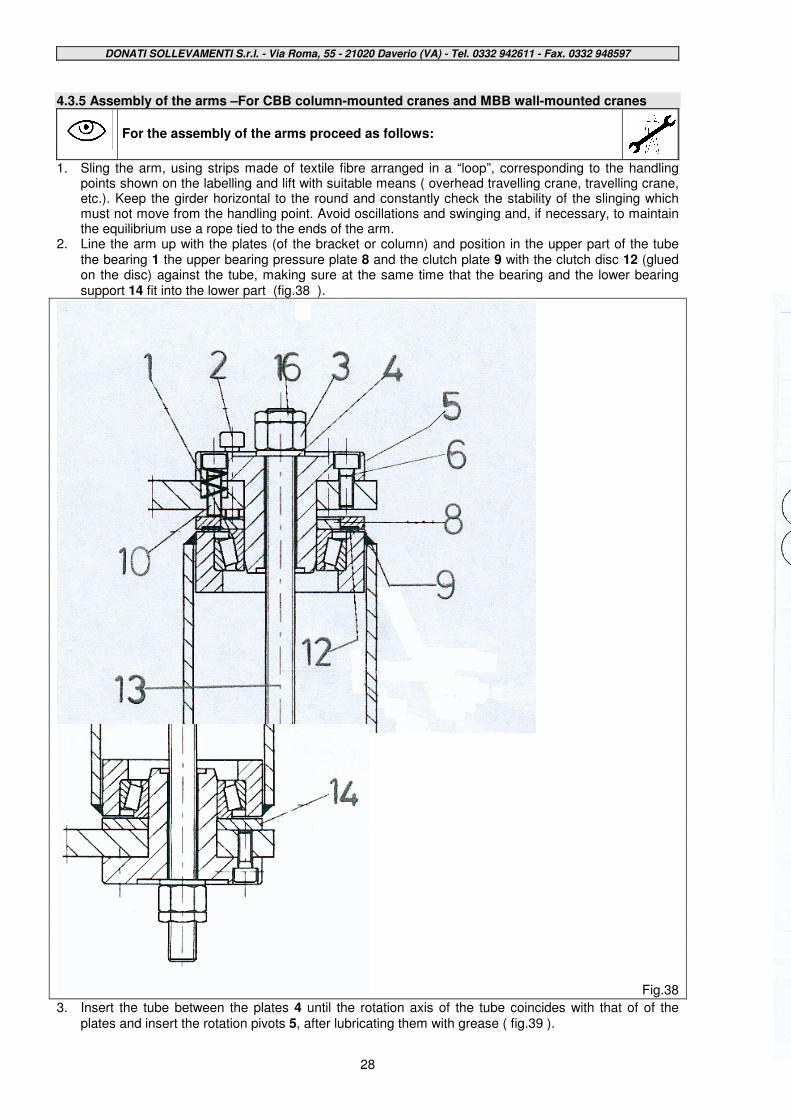
For the assembly of the arms proceed as follows:
1. Sling the arm, using strips made of textile fibre arranged in a “loop”, corresponding to the handling
points shown on the labelling and lift with suitable means ( overhead travelling crane, travelling crane, etc.). Keep the girder horizontal to the round and constantly check the stability of the slinging which must not move from the handling point. Avoid oscillations and swinging and, if necessary, to maintain the equilibrium use a rope tied to the ends of the arm.
2. Line the arm up with the plates (of the bracket or column) and position in the upper part of the tube the bearing 1 the upper bearing pressure plate 8 and the clutch plate 9 with the clutch disc 12 (glued on the disc) against the tube, making sure at the same time that the bearing and the lower bearing support 14 fit into the lower part (fig.38 ).
Fig.38
3. Insert the tube between the plates 4 until the rotation axis of the tube coincides with that of of the plates and insert the rotation pivots 5, after lubricating them with grease ( fig.39 ).
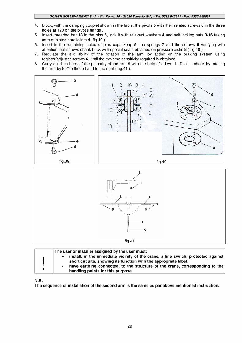
DONATI SOLLEVAMENTI S.r.l. - Via Roma, 55 - 21020 Daverio (VA) - Tel. 0332 942611 - Fax. 0332 948597
29
4. Block, with the camping couplet shown in the table, the pivots 5 with their related screws 6 in the three holes at 120 on the pivot’s flange .
5. Insert threaded bar 13 in the pins 5, lock it with relevant washers 4 and self-locking nuts 3-16 taking care of plates parallelism 4( fig.40 ).
6. Insert in the remaining holes of pins caps keep 5, the springs 7 and the screws 6 verifying with attention that screws shank buck with special seats obtained on pressure disks 8 ( fig.40 ).
7. Regulate the slid ability of the rotation of the arm, by acting on the braking system using register/adjuster screws 6, until the traverse sensitivity required is obtained.
8. Carry out the check of the planarity of the arm 9 with the help of a level L. Do this check by rotating the arm by 90° to the left and to the right ( fig.41 ).
fig.39
fig.40
fig.41
The user or installer assigned by the user must:
• install, in the immediate vicinity of the crane, a line switch, protected against short circuits, showing its function with the appropriate label.
• have earthing connected, to the structure of the crane, corresponding to the handling points for this purpose
N.B. The sequence of installation of the second arm is the same as per above mentioned instruction.
DONATI SOLLEVAMENTI S.r.l. - Via Roma, 55 - 21020 Daverio (VA) - Tel. 0332 942611 - Fax. 0332 948597
30
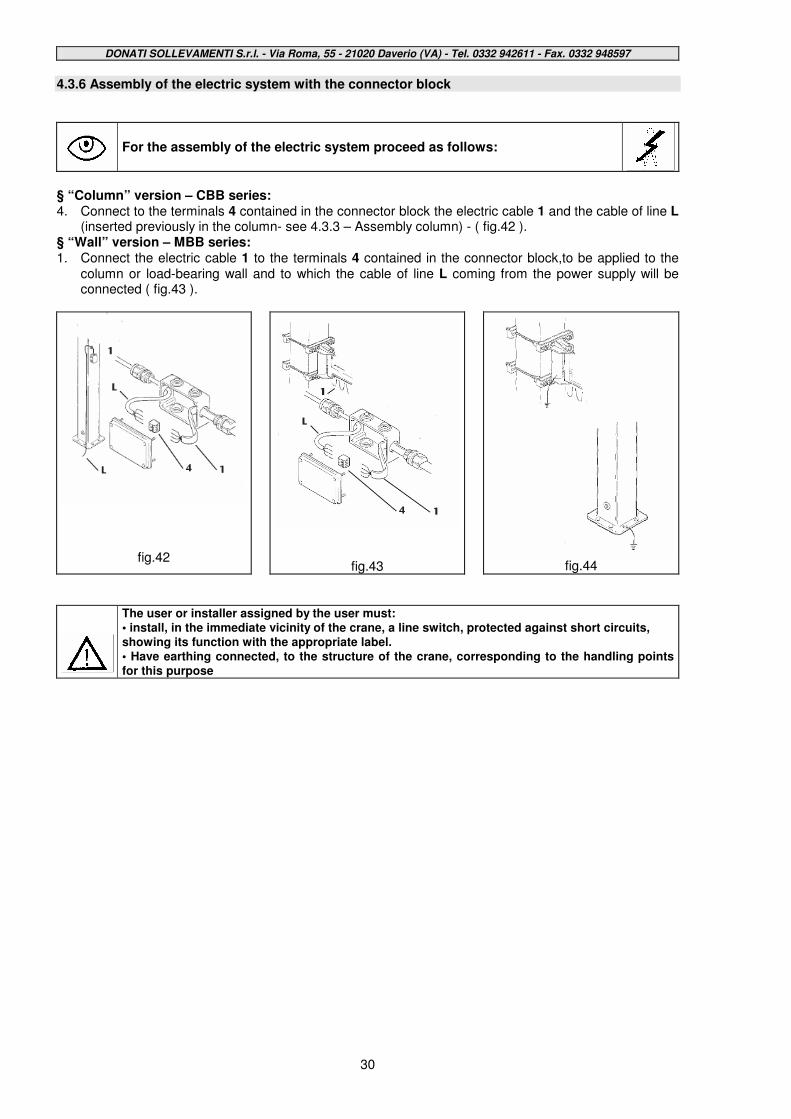
4.3.6 Assembly of the electric system with the connector block
For the assembly of the electric system proceed as follows:
§ “Column” version – CBB series: 4. Connect to the terminals 4 contained in the connector block the electric cable 1 and the cable of line L
(inserted previously in the column- see 4.3.3 – Assembly column) - ( fig.42 ). § “Wall” version – MBB series: 1. Connect the electric cable 1 to the terminals 4 contained in the connector block,to be applied to the
column or load-bearing wall and to which the cable of line L coming from the power supply will be connected ( fig.43 ).
fig.42
fig.43
fig.44
The user or installer assigned by the user must: • install, in the immediate vicinity of the crane, a line switch, protected against short circuits, showing its function with the appropriate label. • Have earthing connected, to the structure of the crane, corresponding to the handling points for this purpose

DONATI SOLLEVAMENTI S.r.l. - Via Roma, 55 - 21020 Daverio (VA) - Tel. 0332 942611 - Fax. 0332 948597
31
4.3.6.1 Assembly of the electric system with isolatine switch for CBB column-mounted cranes
For the assembly of the electric system proceed as follows:
1. Assemble the isolator switch as in figure 45, assembling the components. 2. Position the isolator switch in the hole in the column, connecting the relative electric cables,
finishing the assembly with the application of the yellow frame and of the red knob as in figure 46.
fig.45
fig.46
The user or installer assigned by the user must: •Install, in the immediate vicinity of the crane, a line switch, protected against short circuits, showing its function with the appropriate label. •Have earthing connected, to the structure of the crane, corresponding to the handling points for this purpose ( fig.44 ).
DONATI SOLLEVAMENTI S.r.l. - Via Roma, 55 - 21020 Daverio (VA) - Tel. 0332 942611 - Fax. 0332 948597
32
4.3.7 Assembly of the hoist
Assembly of the hoist on the crane CBB-MBB:
See “Instruction for use” of the hoist ( if supplied) included in this publication
Electrical connection of the hoist:
To connect the festooned cable of the power line to the terminals of the electrical apparatus of the lifting unit, see “ Instruction for use” of the hoist ( if supplied) included in this publication
• Never carry out electrical connections with live power • Never make precarious connections or flying connections • Clamp down completely the cable presses • Procure the electrical circuit diagrams for the hoist/trolley on which you are working
DONATI SOLLEVAMENTI S.r.l. - Via Roma, 55 - 21020 Daverio (VA) - Tel. 0332 942611 - Fax. 0332 948597
33
4.4 - Putting the machine into operation 4.4.1 Preliminary operations - Adjustments and test runs
Before putting the jib crane into use, carry out the following operations:
•••• Check the electrical system is in a suitable condition:
•••• Check that the voltage and line frequency, shown on the respective motor plates, correspond to those designed for the functioning.
•••• Check that the voltage value to the motors is within the limits of +/-10% of the nominal value.
•••• Check there are ground clamps and that they are connected correctly.
•••• Checking the correct installation of the crane:
•••• Check there are no obvious faults following the installation of the crane.
•••• Check that all the bolted joints are correctly tightened.
•••• Check the uniform sensitivity of the flexing of the arm, in all its amplitude.
•••• Check that the arm can freely rotate, related to the absence of obstacles in the whole area of operation of the crane and any interference.
•••• Adjust the ascent limit switches of the electric hoist (see information in the related “Instructions for use”), to allow the maximum possible run. The ascent limit switch must be adjusted so that the hook at its lowest point is about 10 cm from the ground.
•••• Check there are no leaks of lubricant.
•••• Check during the trial runs that there are no strange noises and/or vibrations and/or incorrect movements (skidding of the wheels or, spontaneous movements of the trolley and/or the arm,etc).
•••• Checking the functioning of the correct rotation direction of the motors:
•••• If the crane is fitted with electric hoist:
•••• Operate, for brief distances, the “ascent/descent” buttons, taking care to operate first in one direction (descent), and then in the other (ascent) with two brief impulses necessary only to ascertain the correct direction of rotation, without using any electric limit switches.
• Avoid intervening using the lifting limit switch.
• If the rotation direction of the motors does not correspond to the controls of the push-button control panel the limit switches do not halt the movement, and malfunctioning can occur
• If the direction of the movement does not correspond to the function shown on the push button control panel, halt the manoeuvre.
DONATI SOLLEVAMENTI S.r.l. - Via Roma, 55 - 21020 Daverio (VA) - Tel. 0332 942611 - Fax. 0332 948597
34
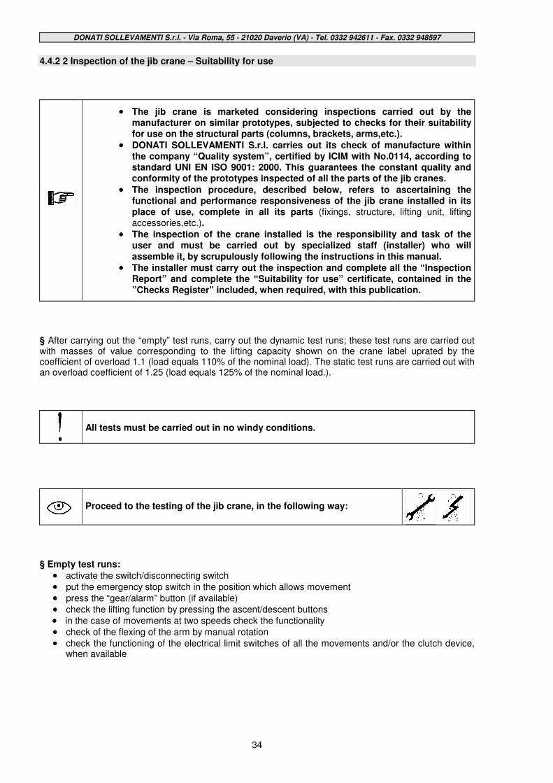
4.4.2 2 Inspection of the jib crane – Suitability for use
•••• The jib crane is marketed considering inspections carried out by the manufacturer on similar prototypes, subjected to checks for their suitability for use on the structural parts (columns, brackets, arms,etc.).
•••• DONATI SOLLEVAMENTI S.r.l. carries out its check of manufacture within the company “Quality system”, certified by ICIM with No.0114, according to standard UNI EN ISO 9001: 2000. This guarantees the constant quality and conformity of the prototypes inspected of all the parts of the jib cranes.
•••• The inspection procedure, described below, refers to ascertaining the functional and performance responsiveness of the jib crane installed in its place of use, complete in all its parts (fixings, structure, lifting unit, lifting accessories,etc.).
•••• The inspection of the crane installed is the responsibility and task of the user and must be carried out by specialized staff (installer) who will assemble it, by scrupulously following the instructions in this manual.
•••• The installer must carry out the inspection and complete all the “Inspection Report” and complete the “Suitability for use” certificate, contained in the ”Checks Register” included, when required, with this publication.
§ After carrying out the “empty” test runs, carry out the dynamic test runs; these test runs are carried out with masses of value corresponding to the lifting capacity shown on the crane label uprated by the coefficient of overload 1.1 (load equals 110% of the nominal load). The static test runs are carried out with an overload coefficient of 1.25 (load equals 125% of the nominal load.).
All tests must be carried out in no windy conditions.
Proceed to the testing of the jib crane, in the following way:
§ Empty test runs:
•••• activate the switch/disconnecting switch
•••• put the emergency stop switch in the position which allows movement
•••• press the “gear/alarm” button (if available)
•••• check the lifting function by pressing the ascent/descent buttons
•••• in the case of movements at two speeds check the functionality
•••• check of the flexing of the arm by manual rotation
•••• check the functioning of the electrical limit switches of all the movements and/or the clutch device, when available
DONATI SOLLEVAMENTI S.r.l. - Via Roma, 55 - 21020 Daverio (VA) - Tel. 0332 942611 - Fax. 0332 948597
35
§ Dynamic test runs:
•••• prepare adequate weights for the test runs with load equal to nominal lifting capacity x 1.1 and suitable equipment for the harnessing and lifting of the load.
•••• harness the load, taking care to position the hook vertically to avoid skew rope falls.
•••• slowly tension the sling so as not to cause tearing, if available do the test runs with load using the “slow” speed.
•••• slowly lift the load and check that this happens with no difficulty and that there are no anomalous noises, clear deformations or sagging in the structure of the crane, in the support structures and/or the anchorings
•••• repeat the test run at maximum speed, if available, doing the preceding checks
•••• check the functionality of the “ascent and descent” limit switches, when installed, and/or any clutch device fitted.
•••• check the functionality of the lifting brake, checking that the weight is braked in adequate time and that there is no skidding of the load, after releasing the button.
•••• carry out the same checks also for the trolley travelling movements and rotation of the arm, checking the functionality of the limit switches, without bringing the load to the maximum height (lift it to a height of one metre from the ground).
•••• operate first at slow speed, if available, and then at maximum speed
•••• check the correct sliding of the trolley on the girder, and ascertain that there are no no anomalous noises, evident permanent deformations or anomalous sagging of the structure of the crane, of the support structure and/or the anchorings.
•••• check the functioning of the “emergency stop” button which must stop and inhibit all the movements. Any function of the hoist and/or trolley must stop, in the shortest possible time and space, without showing anomalies,side skids, dangerous oscillations, etc. which threaten the stability.
•••• check the braking spaces and stopping spaces during lifting travelling and rotation, checking the stability of the mass manoeuvred.
The dynamic test run must be carried out in the most unfavourable load conditions, that is combining lifting and rotation.
§ Static test runs:
•••• use suitable masses for the test runs equal to: nominal lifting capacity x 1.25 and suitable equipment for slinging and lifting the load
•••• put in the sling the load used for the dynamic test runs (nominal capacity x 1.1) taking care to position the hook on the vertical to avoid skew runs
•••• tension the sling slowly to avoid tearing, if available carry out the test runs using the “slow” speed
•••• lift the load and stop it in a suspended position at a height of 10cm
•••• gradually apply weight on it until reaching an overload value equal to 25% of the nominal lifting capacity
•••• leave the weight suspended for no less than 10 minutes.
•••• check that the weight suspended (load + overload) does not yield (the lifting brake and the clutch device/load limiting switch, if installed, must not skid).
•••• release the load and check that there are no evident deformations and/or sagging of the structures of the crane, the support structures and/or the anchorings.
• During the static test run NO movement of the crane must be activated.
• The testing of the jib crane must be repeated at the annual checks (see paragraph 6.3.2)
• The results of the annual testing must be noted in the checks register (see chapter 8) included with this publication, when required.
DONATI SOLLEVAMENTI S.r.l. - Via Roma, 55 - 21020 Daverio (VA) - Tel. 0332 942611 - Fax. 0332 948597
36
4.5 Out of service 4.5.1 Storage and conservation of parts
If the jib crane and its component parts should be put in the warehouse and kept (storage), to avoid damage or deterioration proceed in the following way:
• Protect the machine surfaces of the plates and the mechanisms with antioxidant products, do not scratch the surfaces intended for assembling with other parts or the inside of holes. • The materials are foreseen for indoor or outdoor installation and can be stored for a maximum period of two years in an environment with the following characteristics:
• protected from atmospheric agents • relative humidity no more than 80% • temperatures: minimum –20°C; maximum +60°C
• For a storage period longer than two years ask for conservation procedures from the manufacturer • If these values should change during the storage, it will be necessary to carry out preliminary checks before putting the crane into use (see 4.5.2 “Reuse after storage”) • If in the storage place the temperature exceeds or goes below the values indicated and the relative humidity is more than 80% prepare protection for the packed packages with barrier bags and hygroscopic salts. • For storage in open areas provide:
• raised bases for all items without pallets • protect all items with barrier bags and hygroscopic salts • If the crane has been built to operate outside , the parts of the steel structure do not require special protection;on the contrary, the parts machined on a machine tool (machined surfaces, wheels, pivots, etc.) must be protected with antioxidant products (transparent varnishes, grease,etc.)
4.5.2 Reuse after storage
Before putting the jib crane back into use after a long storage period, the following operations must be carried out:
•••• Structure:
•••• eliminate traces of lubricant from the structure
•••• clean any grease residue from the holes and skim the threads of the holes
•••• clean the mating surfaces at the joints
•••• repair any structural damage (scratched surfaces, peeling paint, etc.)
•••• Mechanisms:
•••• check for any leakage and if necessary, refill the levels of lubricant.
•••• verify that the mechanisms are correctly tightened to the related structure.
•••• eliminate traces of rust from sliding parts which are accessory to the commands.
•••• lubricate the thrust bearing of the hook and the unpainted mechanisms (shafts, etc.).
•••• eliminate any residual water from concave parts.
•••• Electrical equipment:
•••• eliminate any condense from the motors and terminal boards; dry with jets of air
•••• check the integrity and functioning of the brakes
•••• clean the surfaces of the brake gaskets thoroughly, eliminating all traces of humidity, lubricants and varnishes
•••• check the integrity and functioning of the limit switches
•••• check the parts and the electrical components are intact
•••• dry contactor contacts
•••• clean closure surfaces thoroughly, clean threaded holes of all containers
•••• carefully check the functioning and efficiency of the push-button control panel
DONATI SOLLEVAMENTI S.r.l. - Via Roma, 55 - 21020 Daverio (VA) - Tel. 0332 942611 - Fax. 0332 948597
37
5. - FUNCTIONING AND USE OF THE JIB CRANE
5.1 - Functions of the jib crane 5.1.1 Intended use - Foreseen use - Designated use § The manually rotated jib cranes with articulated arm, in the CBB column-mounted version and the MBB wall-mounted version are produced for the manoeuvring of goods inside a building, in a yard or to serve operative positions. . § The jib cranes with articulated arm have two functions:
•••• they lift a load vertically, using the hook of the lifting block, generally made up of a manual or electric chain hoist and using suitable accessories for such an operation;
•••• they rotate the load, around the constraint axis of the arm, by pushing by hand the load, using the surrounding circular area, delineated by the rotation range of the arms.
§ If the crane is fitted with an electric hoist the movements can be activated by:
•••• using the push-button control panel with the push-buttons of “ascent” and “descent” for control of the lifting movement
§ If the crane is fitted with manual hoist the movements are activated by:
•••• mechanical action of the manoeuvre chain of the hoist for lifting § In all cases the rotation movement of the arms is activated manually with push-training. § When it is controlled by the push-button control panel, the push-buttons activate the function when they are held down and control of the auxiliary slow lifting ,it can be activated as follows:
•••• with separate push-buttons which keep the “high” and “low” speed controls separate.
•••• with a single push-button with two positions, the first position is the “low” speed and the second position is the “high” speed
The emergency stop button is red and mushroom-shaped, and activates the stop function when pressed right down. •To allow the jib crane to work it is necessary to bring the emergency stop button to its most “raised” gear speed position and then push the start buttons one after the other. •The push-button control panel is pendant from the hoist and can be used by the operator on the ground while following the travelling movement the rotation of the arms. •The electric movements of the jib crane can also be controlled through a radio-control system, the functions of the buttons are the same as the ones on the pendant push-button panel.
•••• When the jib crane is controlled using the radio-control the push-button panel is not attached to the crane itself, therefore the operator must always take the utmost care during manoeuvres and never lose sight of the work area or of the load being moved so as not to threaten his own safety and/or that of other people present.
•••• It is forbidden to control the jib crane movements while sitting or standing on it.
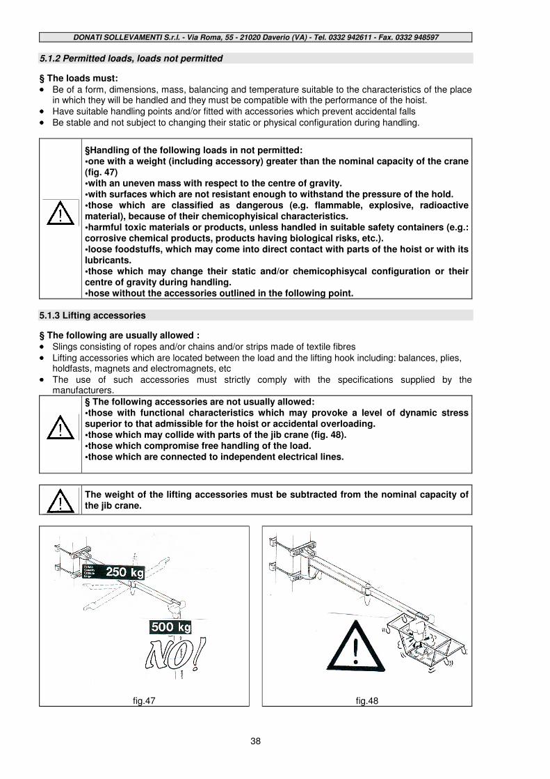
DONATI SOLLEVAMENTI S.r.l. - Via Roma, 55 - 21020 Daverio (VA) - Tel. 0332 942611 - Fax. 0332 948597
38
5.1.2 Permitted loads, loads not permitted
§ The loads must:
•••• Be of a form, dimensions, mass, balancing and temperature suitable to the characteristics of the place in which they will be handled and they must be compatible with the performance of the hoist.
•••• Have suitable handling points and/or fitted with accessories which prevent accidental falls
•••• Be stable and not subject to changing their static or physical configuration during handling.
§Handling of the following loads in not permitted: •one with a weight (including accessory) greater than the nominal capacity of the crane (fig. 47) •with an uneven mass with respect to the centre of gravity. •with surfaces which are not resistant enough to withstand the pressure of the hold. •those which are classified as dangerous (e.g. flammable, explosive, radioactive material), because of their chemicophyisical characteristics. •harmful toxic materials or products, unless handled in suitable safety containers (e.g.: corrosive chemical products, products having biological risks, etc.). •loose foodstuffs, which may come into direct contact with parts of the hoist or with its lubricants. •those which may change their static and/or chemicophisycal configuration or their centre of gravity during handling. •hose without the accessories outlined in the following point.
5.1.3 Lifting accessories
§ The following are usually allowed :
•••• Slings consisting of ropes and/or chains and/or strips made of textile fibres
•••• Lifting accessories which are located between the load and the lifting hook including: balances, plies, holdfasts, magnets and electromagnets, etc
•••• The use of such accessories must strictly comply with the specifications supplied by the manufacturers.
§ The following accessories are not usually allowed: •those with functional characteristics which may provoke a level of dynamic stress superior to that admissible for the hoist or accidental overloading. •those which may collide with parts of the jib crane (fig. 48). •those which compromise free handling of the load. •those which are connected to independent electrical lines.
The weight of the lifting accessories must be subtracted from the nominal capacity of the jib crane.
fig.47
fig.48
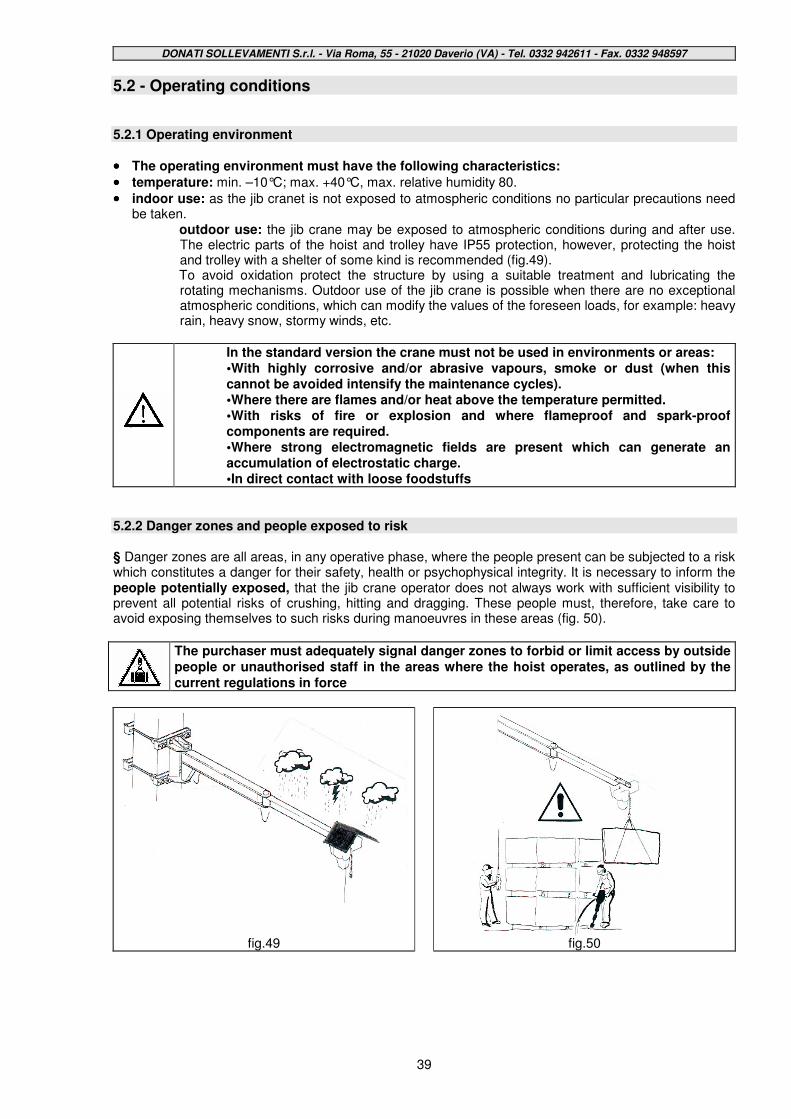
DONATI SOLLEVAMENTI S.r.l. - Via Roma, 55 - 21020 Daverio (VA) - Tel. 0332 942611 - Fax. 0332 948597
39
5.2 - Operating conditions 5.2.1 Operating environment
•••• The operating environment must have the following characteristics:
•••• temperature: min. –10°C; max. +40°C, max. relative humidity 80.
•••• indoor use: as the jib cranet is not exposed to atmospheric conditions no particular precautions need be taken.
outdoor use: the jib crane may be exposed to atmospheric conditions during and after use. The electric parts of the hoist and trolley have IP55 protection, however, protecting the hoist and trolley with a shelter of some kind is recommended (fig.49). To avoid oxidation protect the structure by using a suitable treatment and lubricating the rotating mechanisms. Outdoor use of the jib crane is possible when there are no exceptional atmospheric conditions, which can modify the values of the foreseen loads, for example: heavy rain, heavy snow, stormy winds, etc.
In the standard version the crane must not be used in environments or areas: •With highly corrosive and/or abrasive vapours, smoke or dust (when this cannot be avoided intensify the maintenance cycles). •Where there are flames and/or heat above the temperature permitted. •With risks of fire or explosion and where flameproof and spark-proof components are required. •Where strong electromagnetic fields are present which can generate an accumulation of electrostatic charge. •In direct contact with loose foodstuffs
5.2.2 Danger zones and people exposed to risk § Danger zones are all areas, in any operative phase, where the people present can be subjected to a risk which constitutes a danger for their safety, health or psychophysical integrity. It is necessary to inform the people potentially exposed, that the jib crane operator does not always work with sufficient visibility to prevent all potential risks of crushing, hitting and dragging. These people must, therefore, take care to avoid exposing themselves to such risks during manoeuvres in these areas (fig. 50).
The purchaser must adequately signal danger zones to forbid or limit access by outside
people or unauthorised staff in the areas where the hoist operates, as outlined by the
current regulations in force
fig.49
fig.50

DONATI SOLLEVAMENTI S.r.l. - Via Roma, 55 - 21020 Daverio (VA) - Tel. 0332 942611 - Fax. 0332 948597
40
5.2.3 Illumination of the work area § The column-mounted – series CBB and wall-mounted – series MBB jib cranes do not have their own lighting system. Therefore, the work place of the crane operator must be adequately illuminated in order to guarantee maximum visibility.
•••• The level of illumination must guarantee the maximum level of safety possible for the operation of the crane (fig.51).
•••• The installation of a supplementary lighting system is obligatory in zones with insufficient illumination, avoiding shadows which impede or reduce visibility in the operative and/or neighbouring areas.
5.2.4 The operator
§ The operators are all those who, from time to time, perform the following activities on the jib crane: •transportation, handling, assembling, installation, regulation and testing •starting, use, cleaning, maintenance and repair •disassembly, dismantling, and demolition
•••• The operators must be people suited to the work and psychophysically able to cope with the demands connected to the activities related to the jib crane during all operative phases and in particular during the slinging and handling phases.
•••• The crane operator must position himself so as not to compromise his own safety, foreseeing and/or preventing and, therefore, avoiding possible dropping of the load being transported, and dangerous movements. He must follow the specifications supplied to ensure maximum safety for himself and for others during use of the machine, in particular, he must strictly adhere to the specifications contained in this manual.
•••• The operator must not let anybody come near during the handling of the jib crane and forbid the use to external people, in particular to people under 16 years of age.
•••• The use of the crane is forbidden to non-authorised or untrained people.
•••• The operator must use suitable personal protection devices (PPD = gloves, protective footwear)
5.2.5 The lifting capacity of the jib crane § The lifting capacity of the jib crane, in its original operative configuration, is clearly indicated on a plate attached to it and also to the hook block and is visible from the command post.
• The loading capacity of the crane and its accessories must never be overcome by applying overloads ( fig.52).
•••• The crane must never be equipped with a lifting device (hoist) with a nominal lifting capacity superior to that of the crane.
•••• The speed limit for lifting of 24m/min must never be exceeded if not reducing the lifting capacity of the crane accordingly.
fig.51
fig.52
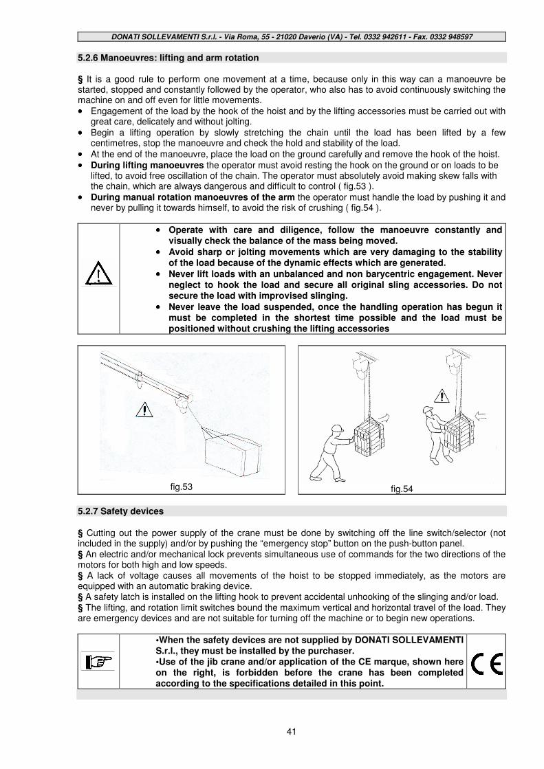
DONATI SOLLEVAMENTI S.r.l. - Via Roma, 55 - 21020 Daverio (VA) - Tel. 0332 942611 - Fax. 0332 948597
41
5.2.6 Manoeuvres: lifting and arm rotation § It is a good rule to perform one movement at a time, because only in this way can a manoeuvre be started, stopped and constantly followed by the operator, who also has to avoid continuously switching the machine on and off even for little movements.
•••• Engagement of the load by the hook of the hoist and by the lifting accessories must be carried out with great care, delicately and without jolting.
•••• Begin a lifting operation by slowly stretching the chain until the load has been lifted by a few centimetres, stop the manoeuvre and check the hold and stability of the load.
•••• At the end of the manoeuvre, place the load on the ground carefully and remove the hook of the hoist.
•••• During lifting manoeuvres the operator must avoid resting the hook on the ground or on loads to be lifted, to avoid free oscillation of the chain. The operator must absolutely avoid making skew falls with the chain, which are always dangerous and difficult to control ( fig.53 ).
•••• During manual rotation manoeuvres of the arm the operator must handle the load by pushing it and never by pulling it towards himself, to avoid the risk of crushing ( fig.54 ).
•••• Operate with care and diligence, follow the manoeuvre constantly and visually check the balance of the mass being moved.
•••• Avoid sharp or jolting movements which are very damaging to the stability of the load because of the dynamic effects which are generated.
•••• Never lift loads with an unbalanced and non barycentric engagement. Never neglect to hook the load and secure all original sling accessories. Do not secure the load with improvised slinging.
•••• Never leave the load suspended, once the handling operation has begun it must be completed in the shortest time possible and the load must be positioned without crushing the lifting accessories
fig.53
fig.54
5.2.7 Safety devices § Cutting out the power supply of the crane must be done by switching off the line switch/selector (not included in the supply) and/or by pushing the “emergency stop” button on the push-button panel. § An electric and/or mechanical lock prevents simultaneous use of commands for the two directions of the motors for both high and low speeds. § A lack of voltage causes all movements of the hoist to be stopped immediately, as the motors are equipped with an automatic braking device. § A safety latch is installed on the lifting hook to prevent accidental unhooking of the slinging and/or load. § The lifting, and rotation limit switches bound the maximum vertical and horizontal travel of the load. They are emergency devices and are not suitable for turning off the machine or to begin new operations.
•When the safety devices are not supplied by DONATI SOLLEVAMENTI S.r.l., they must be installed by the purchaser. •Use of the jib crane and/or application of the CE marque, shown here on the right, is forbidden before the crane has been completed according to the specifications detailed in this point.
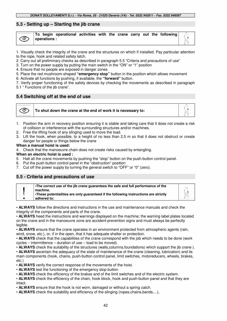
DONATI SOLLEVAMENTI S.r.l. - Via Roma, 55 - 21020 Daverio (VA) - Tel. 0332 942611 - Fax. 0332 948597
42
5.3 - Setting up – Starting the jib crane
To begin operational activities with the crane carry out the following operations :
1. Visually check the integrity of the crane and the structures on which if installed. Pay particular attention to the rope, hook and related safety latch. 2. Carry out all preliminary checks as described in paragraph 5.5 “Criteria and precautions of use” 3. Turn on the power supply by putting the main switch in the “ON” or “1” position 4. Ensure that no people are exposed in danger zones 5. Place the red mushroom-shaped “emergency stop” button in the position which allows movement 6. Activate all functions by pushing, if available, the “forward” button. 7. Verify proper functioning of the safety devices by checking the movements as described in paragraph 5.1 “ Functions of the jib crane”.
5.4 Switching off at the end of use
To shut down the crane at the end of work it is necessary to:
1. Position the arm in recovery position ensuring it is stable and taking care that it does not create a risk
of collision or interference with the surrounding structures and/or machines. 2. Free the lifting hook of any slinging used to move the load. 3. Lift the hook, when possible, to a height of no less than 2.5 m so that it does not obstruct or create
danger for people or things below the crane When a manual hoist is used: 4. Check that the manoeuvre chain does not create risks caused by entangling. When an electric hoist is used : 5. Halt all the crane movements by pushing the “stop” button on the push-button control panel. 6. Put the push button control panel in the “obstruction“ position 7. Cut off the power supply by turning the general switch to “OFF” or “0” (zero).
5.5 - Criteria and precautions of use
•The correct use of the jib crane guarantees the safe and full performance of the machine. •These potentialities are only guaranteed if the following instructions are strictly adhered to:
• ALWAYS follow the directions and instructions in the use and maintenance manuals and check the integrity of the components and parts of the crane. • ALWAYS heed the instructions and warnings displayed on the machine; the warning label plates located on the crane and in the manoeuvre zone are accident-prevention signs and must always be perfectly legible. • ALWAYS ensure that the crane operates in an environment protected from atmospheric agents (rain, wind, snow, etc.), or, if in the open, that it has adequate shelter or protection. • ALWAYS check that the capabilities of the crane correspond with the job which needs to be done (work cycles – intermittence – duration of use – load to be moved). • ALWAYS check the suitability of the structures (walls,columns,foundations) which support the jib crane ). • ALWAYS ascertain the adequacy of the state of maintenance of the crane (cleaning, lubrication) and its main components (hook, chains, push-button control panel, limit switches, motoreducers, wheels, brakes, etc.) • ALWAYS verify the correct response of the movements of the hoist. • ALWAYS test the functioning of the emergency stop button • ALWAYS check the efficiency of the brakes and of the limit switches and of the electric system. • ALWAYS check the efficiency of the chain, hook block, hook and push-button panel and that they are intact. • ALWAYS ensure that the hook is not worn, damaged or without a spring catch. • ALWAYS check the suitability and efficiency of the slinging (ropes,chains,bands,...),
DONATI SOLLEVAMENTI S.r.l. - Via Roma, 55 - 21020 Daverio (VA) - Tel. 0332 942611 - Fax. 0332 948597
43
•••• ALWAYS when moving manually push the load and avoid pulling it towards itself
•••• ALWAYS ensure the lifting unit (hoist and hook) is centered on the perpendicular of the load before slinging and moving it.
•••• ALWAYS appropriately secure the load slings to the lifting hook and stretch the slings with slow, safe movements.
•••• ALWAYS operate in the best conditions as far as lighting and load visibility are concerned.
•••• ALWAYS ensure, before maneuvering, that the rotation of the arm is free from obstacles and that during lifting, travelling and rotation, the load does not meet obstacles
•••• ALWAYS operate outside the maneuvering area of the lifted load.
•••• ALWAYS carry out the handling avoiding jogging.
•••• ALWAYS avoid to cause hunting of the load.
•••• ALWAYS use “slow” speeds for approaching and positioning operations.
•••• ALWAYS at the end of work, position the crane arm, the load hook and the push-button panel, so they are not a collision risk .
•••• ALWAYS push the red emergency stop button on the push-button panel before leaving the command post and switch off the cutout switch of the crane.
•••• ALWAYS switch off power to the machine during checks, repairs, ordinary maintenance.
•••• ALWAYS for all operations, use adequate safety protection devices (DPI, gloves, etc.)
•••• ALWAYS point out any functioning anomalies (faulty working, possible breakings, incorrect movements and unusual noise) to the person in charge of the specific department and put the machine out of service.
•••• ALWAYS follow the maintenance programme and record, for each check, any specific observations, especially regarding the hook, chains, brakes, and limit switches.
5.6 - Contraindications of use
•••• The use of the jib crane for manoeuvres which are not permitted, improper use and a lack of maintenance can carry risks of grave danger for the health and safety of the operator and of the people in the area, as well as risks of damage for the work environment and can compromise the functionality and intrinsic safety of the machine.
•••• The actions described below, which obviously cannot cover the entire range of possible “bad uses” of the crane, are the most predictable ones, and are absolutely forbidden::
5.6.1 Use not intended and not allowed - Foreseeable and unforeseeable inappropriate use • NEVER use the crane to lift and transport people. • NEVER lift loads heavier than the nominal lifting capacity nor equip the crane with hoists with a nominal lifting capacity greater than that of the crane itself. • NEVER lift loads while people are walking under the suspended load. • NEVER walk, stop, operate and maneuver under the suspended load. • NEVER permit unqualified staff or under 16 years of age to use the crane. • NEVER use the crane unless psychophsically suited to the work. • NEVER use the crane unless provided with suitable personal protection (PPD, gloves,etc.) • NEVER operate without taking the necessary care during lifting and travelling and rotation of the arm maneuvers. • NEVER rotate the arms of the crane using the cable of the push button panel • NEVER touch the slings during tensioning in contact with the load and between the hook and the slinging. • NEVER leave the suspended load unattended. • NEVER use the crane for jobs other than those for which it was designed, do not use it for other operations such as painting ceilings, changing light bulbs, a place to rest scaffolding on, etc. • NEVER lift unbalanced loads • NEVER allow the load or the hook to swing during translation or rotation. • NEVER place the chain in a diagonal position for pulling. • NEVER use the crane or its lifting apparatus for pulling or dragging. • NEVER use slingings without having previously checked their suitability. • NEVER use the chain of the hoist for grounding a welder. • NEVER lift loads with the hoist
DONATI SOLLEVAMENTI S.r.l. - Via Roma, 55 - 21020 Daverio (VA) - Tel. 0332 942611 - Fax. 0332 948597
44
•••• NEVER use the crane to keep tension or to extract elements tied to the ground.
•••• NEVER perform a hook run, after having positioned a load, in a way which causes the chain to wobble.
•••• NEVER hit the supporting structures of the building, of machines and systems with the load or the arm.
•••• NEVER use two cranes at the same time to lift the same load .
•••• NEVER employ two simultaneous movements when using the crane, wait until tho movement has come to a complete stop before beginning another.
•••• NEVER use the crane in unforeseen atmospheric conditions or, of installed outside, in hostile, unfavourable and /or dangerous atmospheric conditions (strong wind, heavy rain,etc. ).
•••• NEVER use or act on the hoist in conditions where illumination and/or visibility are insufficient.
•••• NEVER use the crane where the use of flameproof componentry is required.
•••• NEVER use the limit switch devices and the overload device continuously.
•••• NEVER approach at maximum speed the areas of “end of the runs” when rotating.
•••• NEVER use the crane when there is a large drop in the voltage or when one of the phases is lacking.
•••• NEVER perform sudden changes of direction during lifting and rotation operations.
•••• NEVER press the control buttons on the push-button panel repeatedly.
•••• NEVER modify the function characteristics of the crane and/or its components.
•••• NEVER tamper with the settings of the safety-devices (limit switches, clutch device).
•••• NEVER carry out temporary repairs or procedures for putting the machine back into operation which do not comply with the instructions.
•••• NEVER use non-original spare parts or spare parts which have not been recommended by the manufacturer.
•••• NEVER leave the crane at the end of a job without having implemented the safety procedures.
•••• NEVER carry out maintenance, inspections or repairs without having put the crane out of service.
•••• NEVER during maintenance work: • use unsuitable equipment • lean ladders on the column, on the hoist, on the trolley, or on the arm of the crane • work without personal protection devices • carry out work without having removed the load
•••• NEVER use the crane if it is not totally responsive in all its operating functions.
DONATI SOLLEVAMENTI S.r.l. - Via Roma, 55 - 21020 Daverio (VA) - Tel. 0332 942611 - Fax. 0332 948597
45
6. - MAINTENANCE OF THE JIB CRANE
6.1 Safety precautions § The precautions to prevent accidents contained in this paragraph must always be strictly adhered to during maintenance work, with the aim of avoiding damage to staff and to the hoist.
•••• Maintenance staff of the jib crane must:
•••• be well trained
•••• have read this publication
•••• have an excellent knowledge of the accident prevention regulations
•••• Unauthorised staff must be outside the work area during operations
§ Such precautions are covered in greater detail in this chapter, whenever a procedure which may carry a risk of damage or accident is required, through WARNING and DANGER notes:
WARNING notes precede an operation which, if not correctly carried out, may cause damage to the crane and its components..
DANGER notes precede an operation which, if not correctly carried out, may cause injury to the operator.
Pay attention to the following WARNING NOTES during maintenance work:
Before putting the jib crane back into operation after a breakdown, it must be inspected thoroughly and checked for evidence of any damage which may have occurred and the procedure in paragraph 5.3 must be repeated
Never alter the settings or positionings of the safety devices, unless expressly required in order to deal with a breakdown. Tampering with them can cause serious damage to the crane and its components.
DONATI SOLLEVAMENTI S.r.l. - Via Roma, 55 - 21020 Daverio (VA) - Tel. 0332 942611 - Fax. 0332 948597
46
Pay attention to the following DANGER NOTES during maintenance work:
When not required cut out the electricity supply of the crane before carrying out any maintenance work on it. Affix a sign reading: MACHINE UNDER MAINTENANCE – DO NOT INSERT ELECTRICITY SUPPLY
NEVER exclude the safety and protection devices installed on the jib crane. If this became necessary, mark with suitable warning signs and operate with maximum care..
Always check the presence and suitability of earthing connections and that they correspond to regulations. If earthing is not installed with electric equipment serious harm could be done to people.
Avoid use of flammable or toxic solvents (petrol, ether, alcohol, etc.). Avoid long periods of contact with solvents and inhalation of their vapours. Avoid, in particular, use near open flames.
Before turning on the crane always ensure that the maintenance staff are at a safe distance (not at a height) and that tools or other materials have not been left on the crane.
Always use protective gloves during maintenance work.
All accessible moving parts, excluding only the chain and block, must be protected against accidental contact. Put back the protection devices before putting the hoist into operation.
Never use water in case of fire; disconnect all electrical currents and use suitable fire extinguishers.
Ensure that all tools to be used are in perfect condition and have insulating handles where required.
Pay utmost attention to all the REMAINING RISKS highlighted on the hoist and in this publication.

DONATI SOLLEVAMENTI S.r.l. - Via Roma, 55 - 21020 Daverio (VA) - Tel. 0332 942611 - Fax. 0332 948597
47
6.2 The qualifications of maintenance staff. § To be capable to adequately carry out maintenance work of jib cranes maintenance staff must: • know the laws in force related to accident prevention during work carried out on machines with motor transmissions and be able to apply them. • have read and understood chapter 3 “Safety and Accident Prevention”. • be able to use and consult this document. • know the functioning of the machine. • recognise irregularities regarding functioning and when necessary take necessary measures to rectify them. § Professional figures appointed and authorised to carry out maintenance on the crane are:
Operator of the jib crane.
•••• Typical maintenance activities:
•••• Verification of proper functioning of the jib crane. Cooperation with staff appointed to periodical and/or extra maintenance work, after having informed them of any anomalies found in the functioning.
•••• Cleaning and lubrication of the parts of the crane (hoist) which the operator is normally in contact with (push-button panel, hook) and simple maintenance work which does not require intervention at a height (e.g. lubrication of the thrust bearing of the hook).
•••• Technical knowledge required:
•••• knowledge of the functions and use of the jib crane
•••• knowledge of the lubricants utilised in the crane and in the hoist and of the dangers associated with their use.
•••• Qualification required:
•••• suitability to the work in relation to the specific operative and environmental characteristics.
Mechanical maintenance officer
•••• Typical maintenance activities: • mechanical regulation of the clearance of brakes and mechanisms • test movements and mechanical regulation of the safety devices • check mechanical clearance and wear of the components (chain, hook, etc.) • replacement of components which can wear out (chain, hook, chain guide, pulleys) according to this publication • ordinary maintenance of mechanical units after substitution of parts with original spare parts
•••• Technical knowledge required:
•••• good knowledge of mechanical lifting systems and handling with a manual and motor driven system
•••• good knowledge of safety devices used on the hoist (limit switches, brakes, overload switch, etc.)
•••• basic knowledge of the moderately difficult techniques for electric checking and adjustment (limit switch adjustment, replacement of fuses, motor connection, etc.)
•••• knowledge of the methods of measurement and testing to determine the actual state of the conditions of the crane and of the hoist (tests of: brakes, chain and hook wear, anomalous noise, etc.)
•••• logical trouble-shooting methods of non complex breakdowns and evaluation of the results
•••• ability to arrange the necessary measures to put the hoist back into working order
•••• ability to write a maintenance intervention report
•••• Qualification required: •••• Complete training of an industrial mechanic having a specialisation in and experience of lifting-
system maintenance or of industrial handling

DONATI SOLLEVAMENTI S.r.l. - Via Roma, 55 - 21020 Daverio (VA) - Tel. 0332 942611 - Fax. 0332 948597
48
••••
Electrical maintenance officer
•••• Typical maintenance activities:
•••• intervention on the electrical equipment beginning from the electrical circuit diagrams.
•••• test of the execution of movements and electric adjustment of the safety devices.
•••• check of the wear of electrical components (contacts of the electrical equipment).
•••• repairs of the electric units after replacement of parts with original spare parts.
•••• Technical knowledge required:
•••• good knowledge of electrical plants and installations.
•••• good knowledge of the electrical componentry and of the safety devices used in the hoist (limit switches, brakes, etc.).
•••• knowledge of moderately difficult electrical checks and adjustments (replacement according to the original diagrams: motors, limit switches, push-button panel, control console, cables, etc.).
•••• basic knowledge of moderately difficult techniques for mechanical checks and adjustments (wear testing, adjustment of mechanical stops, etc.).
•••• knowledge of the methods of measurement and testing to determine the actual state of the conditions of the hoist (tests of the efficiency and reliability of the electrical equipment).
•••• knowledge of trouble-shooting methods in case of power failure or breakdown and experience of electric command and control systems of lifting and handling equipment.
•••• ability to arrange the necessary measures to put the hoist back into working order.
•••• ability to write a maintenance intervention report.
•••• Qualification required:
•••• Complete training of an industrial electrician having a specialisation in and experience of lifting-system maintenance or of industrial handling.
Electromechanical maintenance officer: He is an operator whose professional profile, as well as including the typical characteristics of the electrical maintenance officer, also combines and synthesizes the competence and abilities required of the mechanical maintenance officer
Mechanical technician
•••• Typical maintenance activities:
•••• mechanical adjustments of the safety devices, calibrations and tests (annual load test).
•••• normal maintenance work after substitution of complex and/or critical mechanical componentry in order to maintain safety levels (fixing components, arm, reducers, motors,etc.).
•••• repair of mechanical units after extra maintenance work has been carried out (structural repairs requiring soldering, mechanical work on board of the crane, etc.).
•••• Technical knowledge required:
•••• knowledge of industrial mechanical lifting and handling systems with proof of specific training.
•••• specific knowledge of safety devices used on the hoist (limit switches, brakes, overload switch, etc.).
•••• basic knowledge of techniques for electric checking and adjustment (motor test).
•••• specific competence about the methods of measurement and testing to determine the actual state of the conditions of the crane and the hoist (test of: brakes, push-button panel, control console, limit switch etc.).
•••• specific competence of logical trouble-shooting methods in case of breakdown and evaluation of the results.
•••• ability to direct the necessary measures to put the jib crane back into working order.
•••• ability to write a maintenance intervention report.
•••• Qualification required: •••• Complete training as industrial mechanical technician and specific competence in lifting and
handling systems.

DONATI SOLLEVAMENTI S.r.l. - Via Roma, 55 - 21020 Daverio (VA) - Tel. 0332 942611 - Fax. 0332 948597
49
••••
Electrical technicians.
•••• Typical maintenance activities:
•••• electrical adjustment of safety devices, calibrations, and tests (annual load test)
•••• normal maintenance work after substitution of complex and/or critical electrical componentry in order to maintain safety levels (lifting limit switch, motors, B.T. switchboard)
•••• repair of electrical units after extra maintenance work has been carried out (repair of the electric motors with partial replacement, replacement of limit switches with variation in position, etc.)
•••• Technical knowledge required:
•••• very good knowledge of electrical systems and installations on industrial lifting and handling equipment • specific knowledge of the electrical componentry and of the safety devices used in the hoist (limit switches, brakes, overload switch, etc.)
•••• experience of the techniques used in electrical checks and adjustments (ability to alter the original diagrams to make improvements on: limit switches, push-button panel, control consoles, cables, etc.)
•••• knowledge of the techniques for mechanical checks and adjustments (wear testing, test performance of mechanical components, adjustment of mechanical stops, test noise level, etc.)
•••• specific competence in the methods of measurement and testing to determine the actual state of the conditions of the hoist (tests of the efficiency and reliability of the electrical equipment) • specific competence in trouble-shooting methods in all types of breakdown and evaluation of the results on the command and control electrical equipment of lifting machines
•••• capacity to manage the measures necessary to put the jib crane and the hoist back into action and performance
•••• ability to write a maintenance intervention report
•••• Qualification required:
•••• Complete training of an industrial electrical technician having a specialisation in and specific experience of electrical apparatus of lifting and handling systems.
Electromechanical technician: He is a highly specialised and specifically trained operator, whose professional profile combines and synthesizes not only the abilities and knowledge typical of the electrical technician, but also those of the mechanical technician.
Special recommendations regarding maintenance:
1.If performed correctly maintenance work guarantees the safety of jib crane operators and reduces downtime to a minimum after a breakdown. 2.Repairs carried out opportunely prevent further deterioration of the crane and its components. 3.Use original spare parts and products. 4.To prepare the crane for maintenance work the following rules must be followed:
•The staff appointed to do the ordinary or extraordinary maintenance work must have read and understood well all the instructions contained in this chapter and in chapter 3. •Extraordinary maintenance work must only be carried out by authorised, qualified staff, trained for the job.
Maintenance work must be carried out, when possible, while the crane is not connected to the power supply and in safe conditions, using suitable tools and adequate personal protection devices, in accordance with the regulations in force, and affixing a sign with the warning: “MAINTENANCE WORK IN PROGRESS”.
For problems which may come about or to order spare parts contact the DONATI SOLLEVAMENTI S.r.l. Technical Assistance Service

DONATI SOLLEVAMENTI S.r.l. - Via Roma, 55 - 21020 Daverio (VA) - Tel. 0332 942611 - Fax. 0332 948597
50
6.3 Maintenance plan
§ The maintenance plan includes ordinary types of work, such as inspections, checks and tests conducted by the operator and/or by qualified staff appointed for normal company maintenance and periodical maintenance, which includes replacement, adjustments and lubrication, carried out by technical staff trained for the job through specific courses and publications.
•••• As maintenance work can be carried out at a dangerous height,
staff must have appropriate means of support (scaffolding,
platform, ladders etc.) which allows the work to be performed in
safe conditions
•••• Staff must also have suitable personal protection devices (PPD) as
set out by legislation in force
6.3.1 Daily and periodical maintenance. § It includes maintenance work which can be performed directly by the crane operator or by qualified staff, as instructed in this publication and/or in attached documentation, which do not require the use of special instruments or equipment. § Maintenance operations are divided into :
Daily intervention to be performed by the crane operator:
• general visual check
• functional checks: motors, limit switches, clutch device, empty test runs, push-button tests of “stopping” and of the other functions of the push-button panel
• check of the state of the chain and hook
• check the correct rotation of the crane arm
Monthly intervention to be performed by qualified staff:
• Visual check of every gear and for possible lubricant leakage
• Function check of the break at full load
• Check that anomalous noise and/or vibration are not present
• See to the lubrication of the gears and limit switches to guarantee normal functioning and to limit wear
• Check the functionality and integrity of the push-button panel and relative cable.
Quarterly checks to be performed by qualified staff: • Check efficiency and wear on: hook, chain and chain guide bar. • Check wear on and hook block/underblock • Verify efficiency and functionality of overload switch • Visual check inside switchboard for the presence of dust • Check and cleaning of oxidised contacts and of any connectors outlets/plugs • cable check • Check efficiency and integrity of electricity supply line and its components • Loaded check of motors and brakes and verify level of wear • Check of efficiency and conservation of the structure (paintwork, corrosion, etc.)
DONATI SOLLEVAMENTI S.r.l. - Via Roma, 55 - 21020 Daverio (VA) - Tel. 0332 942611 - Fax. 0332 948597
51
6.3.2 Frequency and deadlines for maintenance work. §The periodicity of the following operations is for jib cranes used in normal working conditions and is valid up to the M5 group (ISO norm 4301/88) or 2 m (FEM rule 9.511). §If the jib crane is used normally and correctly for a daily 8 hour shift, overhaul can take place after a period of about 10 years (FEM rule 9.755 – S.W.P.). If used during a number of shifts then the maintenance periods must be reduced proportionately.
Table of periodic checks and maintenance
Periodic checks Object of the check
⇓ Daily Monthly Quarterly � Annuallyi �
Page
Checks Inspections - Testing
General visual checks.Verify
good unctioning
General visual
inspections
Wear check
Annual
test
33
Signs pictograms warning signs and plates
Legibility of signs and
pictograms, warning signs
and plates
Visual inspections
of wholeness and clening of
plates and signs
Check
suitability
18
Structural elements Welding Pivots Bolted couplings
Wear and efficiency check
Check bolted and soldered
joints
52
Chain Securing elements
Visual inspection
Wear and
efficiency check
Hoist
manual
Lifting hook
Visual inspection and check safety
latch
Wear and
efficiency check
Hoist
manual
Load whorl Chain guide Transmission of the hook block
check Wear and efficiency
Hoist
manual
Lifting reducer
Noise check
Hoist
manual
Lifting motor
Check correct
functioning
Loaded testing
Hoist
manual
Lifting brake Rotation brake
Check correct
functioning
Loaded testing
of braking distances
Loaded testing
Wear check
Hoist manual
and page 53
Rotation bearings
Wear check
Hoist manual
and page 52
anti-collision lug
Visual check
Wear and efficiency
check
Hoist manual
and page 52
Electrical system Push-button panel and cable
Check correct functioning
Visual inspection for
external breakage
push-button panel/cable
Wear and efficiency check
Hoist
manual and
page. 53
Overload switch Clutch device
Loaded testing
Calibration
check
Hoist
manual
Lifting limit switch
Check correct functioning
Loaded testing Wear and
efficiency check
Hoist
manual
Cleaning and lubrication
Check correct state of
cleanliness and lubrication
Inspection of general
lubrication
Leakage check Rubricate
chain,hook and mechanisms
Hoist manual
and page 54
NOTE: The following operations must be carefully recorded in the appropriate checks register (see chapter 8)
DONATI SOLLEVAMENTI S.r.l. - Via Roma, 55 - 21020 Daverio (VA) - Tel. 0332 942611 - Fax. 0332 948597
52
6.3.3 Check of efficiency of parts and components.
For the individual parts of the jib crane the following instructions must be strictly adhered to:
Annual check of the efficiency of structural elements, welding, pivots and bolted couplings ( fig.54 ):
•••• The metal structures of the jib crane, as well as normal alterations due to environmental factors and wear of mobile parts (hinges), can be subject, even inadvertently or during handling operations, to bumps, contact or grazing with other equipment or to anomalous strain which can cause damage to the frames, welding and pivots. Therefore, after careful cleaning, the structures must periodically undergo scrupulous checks to ensure their suitability and if necessary, any damage be remedied.
•••• The brackets, composed of plates and pivot, which form hinged elements, are subject to wear as they are mobile, swinging elements exposed to sliding friction in the areas of contact. If excessive wear is found, substitute them during the check.
•••• All screw bolts, high resistance plugs and pins must be disassembled and carefully checked annually, and so must the relative seatings.
•••• Check the clamping couple of the fixing bolts of the column and the bracket, according to the given couples (see tables on page 12).
Repair or substitute hinged parts where one finds: • deformation: lengthening, crushing, staining, bending • wear: worn parts, scarcement, incisions, abrasions, corrosion, oxidation, scratching, peeling point • breakage: cracks in the welding, cracking, cuts or incisions, broken parts • variation of a section ≥10%, or of the diameter or thickness ≥5% compared to initial values
TECNICO DONATI
DONATI
SERVICE
fig.54
DONATI SOLLEVAMENTI S.r.l. - Via Roma, 55 - 21020 Daverio (VA) - Tel. 0332 942611 - Fax. 0332 948597
53
Quarterly check of the efficiency of the brake of the rotation arm of the crane:
• Check the stability of the arms when empty and when fully loaded, at the end points and intermediate points of rotation; then checking that the arms, in any point of the rotation, keeps its position with moving spontaneously.
• When necessary have the brake of the crane adjusted, as described in paragraph 6.4.1 “Adjustment of the rotation brake of the crane arm”, on page 55.
• Replace the clutch plates of the brake when there is instability of the arm
after adjusting the brake.
IN CASE OF ANOMALIES:
• It is forbidden to carry out corrective maintenance work on the brake of the
rotation arm of the jib crane.
• Any operation, outside normal maintenance, on the brake of the rotation
arm of the crane can be done by the assistance service of DONATI
SOLLEVAMENTI S.r.l. or by staff authorized by them.
TECNICO DONATI
DONATI
SERVICE
Quarterly check of the efficiency of the electric power supply:
•••• Check the efficiency of the power cable, check there is no peeling, cuts , lacerations or other changes in the protection sheath.
•••• Check the seal of the protectors, the power cable, their clamps (in the connector block) and, if necessary, tighten them correctly.
•••• Check the efficiency of the conductors and the grounding connections, carrying out a check, and, if necessary, fixing all the grounding screws.
•••• Carry out a check of all the weather strips of the covers and the cable clamps.
•••• Check there are warning plates and that they are visible.
•••• Do non hesitate to replace the electrical component, if it is no longer giving sufficient guarantee of functional reliability
•••• Never carry out improvised repairs
•••• Use original spare parts
For information about checks of all the structural, mechanical and electromechanical components of the lifting units of the jib crane, see the relevant documentation included in this technical publication .
• Don’t hesitate to replace the part and /or the component in question, when it no longer gives sufficient guarantee of safety and/or functional reliability.
• Never carry out improvised repairs!
DONATI SOLLEVAMENTI S.r.l. - Via Roma, 55 - 21020 Daverio (VA) - Tel. 0332 942611 - Fax. 0332 948597
54
6.3.4 Cleaning and lubrication of the jib crane
• Cleaning can be carried out by staff who are not highly specialised.
• It is necessary to keep clean the following elements at regular intervals:
• structure of the jib crane (column, bracket, arm,etc.)
• mechanisms of the jib crane (pivots, braking device)
• electric parts of the jib crane (festooned cable, sleds,etc.)
• components of the lifting unit (wheels, chain, hook, hook block, push-button panel,etc.)
• Cleaning at a height must be carried out by qualified staff equipped with suitable means and personal protection measures.
• These operations are ecessary every three months to allow the performing of the periodical checks.
•••• Cleaning can be simply done using means, equipment, and detergents and solvents commonly
used in general cleaning operations of industrial equipment as there are no particular
controindications regarding the use of products or materials.
•••• Clean away any foreign fouling substances with aspirators, absorbent cloths, etc.
•••• Dry the grease and/or oil in excess on the parts.
The careful lubrication of the mechanism of the jib crane is necessary to guarantee the efficient service the hoist is intended for, as well as its duration.
• Over time the lubricating power is diminished due to the load stress, therefore proceed to the adjustment or renewal of the lubricants. • The lubrication of the jib crane is very easy: apply a light amount of oil or grease, between the bearings and pivots, in the rotation points of the arm. • It is very important to lubricate the lifting and translation mechanisms and the lubrication cycles for them are contained in the relevant technical publications included with this one.
•••• Lubricants, solvents and detergents are products which are toxic or damaging to health
•••• If they come into direct contact with the skin they can cause irritation
•••• If inhaled they can cause serious poisoning
•••• If swallowed they can cause death
•••• Use them with care using adequate personal protection measures (DPI) Do not dump them, dispose of them in conformity with the legislative measures currently in force for toxic/harmful waste.
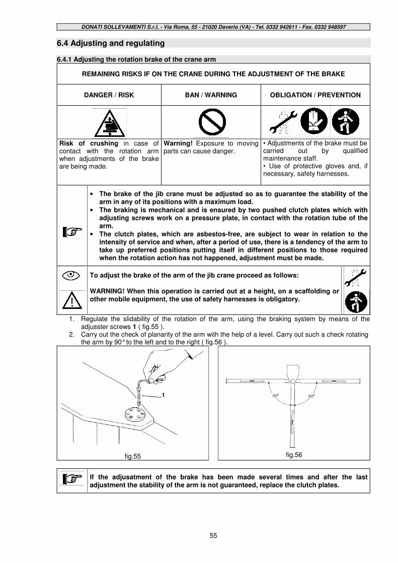
DONATI SOLLEVAMENTI S.r.l. - Via Roma, 55 - 21020 Daverio (VA) - Tel. 0332 942611 - Fax. 0332 948597
55
6.4 Adjusting and regulating 6.4.1 Adjusting the rotation brake of the crane arm
REMAINING RISKS IF ON THE CRANE DURING THE ADJUSTMENT OF THE BRAKE
DANGER / RISK
BAN / WARNING
OBLIGATION / PREVENTION
Risk of crushing in case of contact with the rotation arm when adjustments of the brake are being made.
Warning! Exposure to moving parts can cause danger.
• Adjustments of the brake must be carried out by qualified maintenance staff. • Use of protective gloves and, if necessary, safety harnesses.
• The brake of the jib crane must be adjusted so as to guarantee the stability of the arm in any of its positions with a maximum load.
• The braking is mechanical and is ensured by two pushed clutch plates which with adjusting screws work on a pressure plate, in contact with the rotation tube of the arm.
• The clutch plates, which are asbestos-free, are subject to wear in relation to the intensity of service and when, after a period of use, there is a tendency of the arm to take up preferred positions putting itself in different positions to those required when the rotation action has not happened, adjustment must be made.
To adjust the brake of the arm of the jib crane proceed as follows: WARNING! When this operation is carried out at a height, on a scaffolding or other mobile equipment, the use of safety harnesses is obligatory.
1. Regulate the slidability of the rotation of the arm, using the braking system by means of the adjusster screws 1 ( fig.55 ).
2. Carry out the check of planarity of the arm with the help of a level. Carry out such a check rotating the arm by 90° to the left and to the right ( fig.56 ).
fig.55
fig.56
If the adjusatment of the brake has been made several times and after the last adjustment the stability of the arm is not guaranteed, replace the clutch plates.

DONATI SOLLEVAMENTI S.r.l. - Via Roma, 55 - 21020 Daverio (VA) - Tel. 0332 942611 - Fax. 0332 948597
56
6.5 Breakdowns and solutions 6.5.1 Main types of failure or breakdowns and possible solutions § In the columns of the table that follows the main conditions of bad functioning are shown, which can be reasonably foreseen and the type of problem, the potential cause of the breakdown and possible solutions.
Type of failure
Possible causes of breakdown
Possible solution
Rotation is blocked
• a foreign body has entered the rotation
• seizure of the bearings
• remove the foreign body
• replace the bearings
Difficult rotation
• scant lubrication of the bearings
• lubricate
Instability of the positioning
of the arm
• excessive leaning of the rotation axis
• check the verticality of the crane and the clamping of the fixing system
6.5.2 Authorised staff for intervention in case of breakdown The staff authorised to intervene in most cases of breakdown, or where not indicated differently, are expert maintenance people or trained with a specific preparation on mechanical and electrical parts. Where shown, however, the intervention of specialised suitably-trained staff or the technical staff of the manufacturer is necessary 6.5.3 Putting out of service § If the jib crane cannot be repaired, proceed to the putting out of service operations, signalling the breakdown with a sign; request the intervention of the assistance service.
6.6 Dismantling, disposal and scrapping
If the jib crane or its components, whether broken, worn out or at the end of their designated life, should no longer be usable nor repairable their demolition must be carried out.
•The demolitiion of the jib crane must be carried out using suitable equipment chosen according to the nature of the material on which to intervene (e.g.: shears, oxyhydrogen flame,saw, etc...) •All the components must be dismantled and scrapped having been reduced to small pieces so that none of them can reasonably be used again. •When the jib crane is scrapped their parts must be disposed of taking into account the different nature of them (metals, oils and lubricants, plastic, rubber, etc.) using possibly specialised companies and in any case according to what the relevant law requires regarding solid industrial waste.
Do not try to use again parts or components of the jib crane which look intact but, after checks and/or replacements carried out by specialised staff, or by the manufacturer itself, have been declared no longer fit for use

DONATI SOLLEVAMENTI S.r.l. - Via Roma, 55 - 21020 Daverio (VA) - Tel. 0332 942611 - Fax. 0332 948597
57
7. - SPARE PARTS
•••• The jib cranes are designed and manufactured, so as not to normally require spare parts DUE TO BREAKDOWNS or BREAKAGES, if used correctly and according to adequate maintenance as described in this manual.
•••• If necessary, consult the “jib crane components and spare parts”
•••• The parts and components subjected to normal wear and tear or deterioration are to be obtained from the manufacturer for a minimum period of 10 years.
•••• Do not hesitate to replace the part and/or component under examination, if it does not give sufficient safety guarantees and/or functional reliability.
•••• Never carry out improvised repairs.!
If it is necessary to replace broken parts it is compulsory to use only original spare parts, requesting them directly from:
DONATI SOLLEVAMENTI S.r.l. Via Roma, 55 - 21020 Daverio (VA) Tel. (0332) 942611 - Fax. (0332) 948597
The use of non-origianl spare parts, as well as cancelling the warranty, can threaten the good functionings of the jib crane.
8. - THE CHECKS REGISTER In order to record the correct use of all the control and maintenance activities of the jib crane, as well as to keep trace of any possible responsibilities regarding the activities carried out, as described in this publication, it is recommended that the checksntrol register is compiled diligently and maintained for all the foreseeable life of the hoist (10 years), as prescribed by RES.4.4.2b in the Enclosure 1 of the Machines Directive 98/37/CE ex 89/392/CEE, included with this publication. In the checks register, as well as all the activities regarding the life and use of the jib crane (replacing parts, servicing, breakdowns of some importance), all the operations foreseen in the quarterly and annual maintenance plan, as shown in the “Table of periodical interventions of checking and maintenance”, point 6.3.2, must be noted down. The maintenance officer appointed by the client will have the responsibility of compiling this register in all its parts recording results and any notes in the spaces provided. The name of the maintenance officer and date of the check must also be clearly indicated.


![Pillar and wall-mounted slewing jib cranes · Max. load capacity [kg] Electric slewing Pillar-mounted slewing jib cranes Wall-mounted slewing jib cranes Jib type/design Max. outreach](https://static.fdocuments.in/doc/165x107/5b535fa87f8b9ae30b8be93d/pillar-and-wall-mounted-slewing-jib-cranes-max-load-capacity-kg-electric.jpg)


