
J.GODWIN PONSAM S.CHRISTOBEL DIANA ASST ... SRM University, Kattankulathur 1 School of Computing,...
134
COMPUTER NETWORKS & IT 0305 FIFTH SEMESTER J.GODWIN PONSAM & S.CHRISTOBEL DIANA ASST.PROFESSOR SRM University, Kattankulathur 1 8/22/2011 School of Computing,
Transcript of J.GODWIN PONSAM S.CHRISTOBEL DIANA ASST ... SRM University, Kattankulathur 1 School of Computing,...

COMPUTER NETWORKS & IT 0305 FIFTH SEMESTER
J.GODWIN PONSAM & S.CHRISTOBEL DIANA
ASST.PROFESSORSRM University, Kattankulathur
18/22/2011School of Computing,

UNIT II
• Switching Methods• Transmission Media• Framing• Error Detection & Correction Methods• Sliding Window Protocol• Encoding Techniques• HDLC
8/22/2011School of Computing, Department 2

Circuit Switching
(a) Circuit switching.(b) Packet switching.

Switching Schemes
(1) Circuit Switching
(2) Packet Switching (Store‐and‐Forward)

Circuit Switching
• Circuit Switching‐When the user places a telephone callthe switching equipment within the telephone systemseeks out a physical copper path all the way from ourtelephone to the receiver
• When a call passes through a switching office physicalconnection is established between the sender and thereceiver
• Copper connection is the dedicated path between bothends that exists and continue to exists until the call iscompleted
• Minimum time between start of ringing and end ofdialing is 10sec(Exceed for long distance calls) during thistime interval phone system will be hunting for a copperpath
• No Congestions

Circuit Switching
1. Control message sets up a path from origin todestination
2. Return signal informs source that datatransmission may proceed
3. Data transmission begins4. Entire path remains allocated to thetransmission (whether used or not)
5. When transmission is complete, sourcereleases the circuit

Circuit SwitchingTi
me
A B C D
Data
Call accept signal
Call request signal
DataTransmission
Time
Propagation Delay
Routers/Switches
TransmissionDelay

Packet Switching
• Messages are split into smaller pieces calledpackets
• These packets are numbered and addressedand sent through the network one at a time
• Utilizes the path for a very small time• Router forward the packet before the nextpacket arrives (Reduces the delay, Improvingthe throughput)

Packet SwitchingTi
me
A B C D
Pkt 1
Pkt 2
Pkt 3Pkt 1
Pkt 2
Pkt 3 Pkt 1
Pkt 2
Pkt 3
TransmissionDelay
Header

Switched Networks
Circuit Switched
■ ■ ■
Packet Switched
store-and-forward

Datagram
• Each packet treated independently
• Packets can take any practical route
• Packets may arrive out of order
• Packets may go missing
• Up to receiver to re‐order packets and recover from missing packets

Comparisons
Item CircuitSwitched
PacketSwitched
1. Dedicated Copper Path Yes No
2. Bandwidth available Fixed Dynamic
3. Store and forwardtransmission
No Yes
4. Each path follows the sameroute
Yes No
5. Call setup Required Not needed
6. When can congestion occur At set up time On everypacket
7. Charging Per min Per packet

Twisted Pair
• Physical media which is used for transmissionis known as transmission media
Transmission Media types:
• Guided Media – wire (Twisted pair, Fiberoptics, coaxial cable)
• Unguided – wireless

Twisted Pair
• Transmission time is measured in minutes orhours
• Structure: Consists of two insulated twistedcopper wires typically about 1mm thick
• Twisted pairs can run several kilometerswithout amplification but for longer distancesrepeaters are needed
• Twisted pairs can be used for either analog ordigital transmission
• Twisted pairs are widely used because of their

Twisted Pair
Varieties
• Category 1
• Category 2
• Category 3
• Category 4
• Category 5

Unshielded and Shielded TP
• Unshielded Twisted Pair (UTP)– Ordinary telephone wire
– Cheapest
– Easiest to install
– Suffers from external EM interference
• Shielded Twisted Pair (STP)– Metal braid or sheathing that reduces interference
– More expensive
– Harder to handle (thick, heavy)

Twisted Pair
• Category 3 twisted pairs consists of twoinsulated wires twisted together(10 mbps)
• Four such pairs are typically grouped togetherin a plastic cover for protection and to keep 8wires together
Category 5• More twisted pair per cm which results in lesscrosstalk and better quality signal over longdistance
• Suitable for high speed computer

Twisted Pair
(a) Category 3 UTP.(b) Category 5 UTP.

Coaxial cable
• Coaxial cable also known as coax has a singlecoated copper wire center and an outer metalmesh that acts as both grounding circuit andan electromagnetic shield to reduceinterference
• Outer layer is the plastic cable jacket
• Coax cable connects to a hosts NIC and otherdevices with a barrel connector
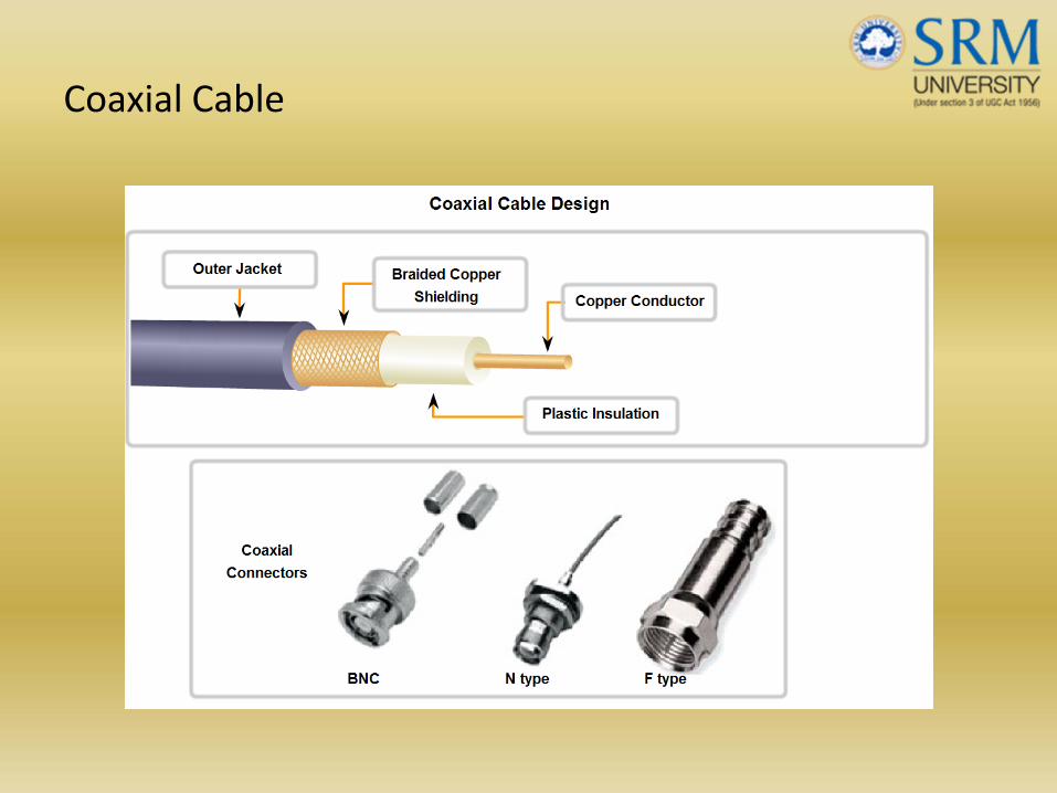
Coaxial Cable

Coaxial Cable

Coaxial Cable

Fiber Optic

Fiber Media
• Fiber optic cable uses light pulses conductedthrough special glass conductors to carry data
• Cladding‐ Material that reflects escaping lightinto the core
• Adv: Greater bandwidth, Can run much fasterthan cable without needing a signal enhanced
• Disadv : Higher cost , special training for installingfiber
• Fiber optic cable can carry light in only onedirection so fiber cable usually include a pair offiber cores

Fiber Optic
• Light generated by either a laser or LED that convertsthe data to light pulses
• Receiving end photodiode interpret the light signaldecode the bit pattern
• Single Mode Fiber‐ Long run,
• Multi Mode Fiber‐ Short run

Fiber Optic

Fiber Optic

I.TComputer Networks
J. Godwin Ponsam
• The DLL provides these services to the Network Layer aboveit:
• Data handed to a DLL by a Network Layer on one module, arehanded to the Network Layer on another module by that DLL.
• The remote Network Layer peer should receive the identicalmessage generated by the sender (e.g., if the data link layeradds control information, the header information must beremoved before the message is passed to the NetworkLayer).
• The Network Layer may want to be sure that all messages itsends, will be delivered correctly (e.g., none lost, nocorruption).
Elementary Data Link Protocols

I.TComputer Networks
J. Godwin Ponsam
• Frames are the unit of transmission. Consists of data plus control bits (header information).
• Of special interest is typedef struct frame;
• void wait_for_event( event_type *event );
• wait_for_event() suspends the process until an event occurs.
Elementary Data Link Protocols


I.TComputer Networks
J. Godwin Ponsam
#define MAX PKT 1024 /* determines packet size in bytes */
typedef enum {false, true} boolean; /* boolean type */typedef unsigned int seq_nr; /* sequence or ack
numbers */
typedef struct {unsigned char data[MAX PKT];
} packet; /* packet definition */typedef enum {data, ack, nak} frame_kind; /* frame kind definition */
typedef struct { /* frames are transported in this layer */frame_kind kind; /* what kind of a frame is it? */seq_nr seq; /* sequence number */seq_nr ack; /* acknowledgement number */packet info; /* the network layer packet */
} frame;
Elementary Data Link Protocols

I.TComputer Networks
J. Godwin Ponsam
Elementary Data Link Protocols/* 1. Wait for an event to happen; return its type in event. */void wait_for_event(event_type *event );/* 2. Fetch a packet from the network layer for transmission on the channel. */void from_network_layer( packet *p);/* 3. Deliver information from an inbound frame to the network layer. */void to_network_layer( packet *p);/* 4. Go get an inbound frame from the physical layer and copy it to r. */void from_physical_layer( packet *p);/* 5. Pass the frame to the physical layer for transmission. */void to_physical_layer( packet *p);/* 6. Start the clock running and enable the timeout event. */void start_timer(seq_nr k);/* 7. Stop the clock and disable the timeout event. */void stop_timer(seq_nr k);/* 8. Start an auxiliary timer and enable the ack_timeout event. */void start_ack_timer(void);/* 9. Stop the auxiliary timerand disable the ack_timeout event. */void stop_ack_timer(void);/* 10. Allow the network layer to cause a network_layer_event. */void enable_network_layer( void );/* 11. Forbid the network layer from causing a network_layer_event. */void disable_network_layer( void );

I.TComputer Networks
J. Godwin Ponsam
Elementary Data Link Protocols
An Unrestricted Simplex ProtocolAssumptions:
Data transmission in one direction only (simplex).
No errors take place on the physical channel.
The sender/receiver can generate/consume an infinite amount of data.
Always ready for sending/receiving.

I.TComputer Networks
J. Godwin Ponsam
Elementary Data Link Protocols/* Protocol 1 (utopia) provides for data transmission in one direction only,
from sender to receiver. The communication channel is assumed to be error free,and the receiver is assumed to be able to process all the input infinitely fast. Consequently, the sender just sits in a loop pumping data out onto the line as fast as it can. */
typedef enum {frame_arrival} event_type;
#include "protocol.h"
void sender1(void)
{
frame s; /* buffer for an outbound frame */
packet buffer; /* buffer for an outbound packet */
while (true) {
from_network_layer(&buffer); /* go get something to send */
s.info = buffer; /* copy it into s for transmission */
to_physical_layer(&s); /* send it on its way */
}
}

void receiver1(void)
{
frame r;
event_type event; /* filled in by wait, but not used here */
while (true) {
wait_for_event(&event); /* only possibility is frame arrival */
From_physical_layer(&r); /* go get the inbound frame */
To_network_layer(&r.info); /* pass the data to the network layer */
}
}

I.TComputer Networks
J. Godwin Ponsam
Elementary Data Link Protocols
Simplex Stop and Wait Protocol
Assumptions:
How to prevent the sender from flooding the receiver
Sender ships one frame and then waits for acknowledgment (stop and wait.)
The contents of the acknowledgment frame are unimportant.

Stop and WaitFigure 10-10

I.TComputer Networks
J. Godwin Ponsam
Elementary Data Link Protocols/* Protocol 2 (stop‐and‐wait) also provides for a one‐directional flow of data from sender to receiver. The communication
channel is once again assumed to be error free, as in protocol 1. However, this time, the receiver has only a finite buffer capacity and a finite processing speed, so the protocol must explicitly prevent the sender from flooding the receiver with data faster than it can be handled. */
typedef enum {frame_arrival} event_type;
#include "protocol.h"
void sender2(void)
{
frame s; /* buffer for an outbound frame */
packet buffer; /* buffer for an outbound packet */
event_type event; /* frame_arrival is the only possibility */
while (true) {
from_network_layer(&buffer); /* go get something to send */
s.info = buffer; /* copy it into s for transmission */
to_physical_layer(&s); /* send it on its way */
wait_for_event(&event); /* do not proceed until given the go ahead */
}
void receiver2(void)
{
frame r, s;
event_type event; /* filled in by wait, but not used here */
while (true) {
wait_for_event(&event); /* only possibility is frame arrival */
From_physical_layer(&r); /* go get the inbound frame */
To_network_layer(&r.info); /* pass the data to the network layer */
to_physical_layer(&s); /* send a dummy frame to awaken sender */
}

I.TComputer Networks
J. Godwin Ponsam
Elementary Data Link ProtocolsSIMPLEX PROTOCOL FOR A NOISY CHANNEL:
Assumptions:
The channel is noisy and we can lose frames (they never arrive).
Simple approach, add a time‐out to the sender so if no ACK after a certain period, it retransmits the frame.
Scenario of a bug that could happen if we’re not careful:
A transmits frame one
B receives A1
B generates ACK
ACK is lost
A times out, retransmits
B gets duplicate copy of A1 (and sends it on to network layer.)
Use a sequence number. How many bits? 1‐bit is sufficient for this simple case because only concerned about two successive frames.
Positive Acknowledgment with Retransmission (PAR): Sender waits for positive acknowledgment before advancing to the next data item. (Numerous alternatives to this we will see later.)

I.TComputer Networks
J. Godwin Ponsam
/* Protocol 3 (par) allows unidirectional data flow over an unreliable channel. */#define MAX_SEQ 1 /* must be 1 for protocol 3 */typedef enum {frame_arrival, cksum_err, timeout } event_type;#include "protocol.h“
void sender3(void){
seq_nr next_frame_to_send; /* Seq number of next outgoing frame */frame s; /* buffer for an outbound frame */packet buffer; /* buffer for an outbound packet */event_type event; /* frame_arrival is the only possibility */next_frame_to_send = 0;from_network_layer(&buffer); /* go get something to send */
while (true) {s.info = buffer; /* copy it into s for transmission */s.seq = next_frame_to_send; /* insert sequence number in frame */to_physical_layer(&s); /* send it on its way */start_timer( s.seq); /* if answer takes too long, time out */wait_for_event(event(&event); /* frame arrival or cksum err, or timeout */if ( event == frame_arrival) {
from_physical_layers(&s); /* Get the ACK */if ( s.ack == next_frame_to_send ) {from_network_layer( &buffer ); /* get the next one to send */inc( next_frame_to_send ); /* invert next_frame_to_send */
} }
}}
Elementary Data Link Protocols

I.TComputer Networks
J. Godwin Ponsam
void receiver3(void){
seq_nr frame_expected;frame r, s;event_type event; frame expected=0;while (true) {wait_for_event(&event); /* only possibility is frame arrival */if ( event == frame_arrival ) { /* A valid frame has arrived */
from_physical_layer(&r); /* go get the inbound frame */if ( r.seq == frame_expected ) { /* This is what we’ve been waiting
for */to_network_layer(&r.info); /* pass the data to the network
layer */inc(frame_expected); /* next time expect the other seq #
*/}
to_physical_layer(&s); /* send a dummy frame to awaken sender */}
}}
Elementary Data Link Protocols

I.TComputer Networks
J. Godwin Ponsam
A Problem unresolved by this protocol is this:
How long should the timer be?
What if too long? (inefficient)
What if too short? A problem because the ACK does not contain the sequence number of the frame which is being ACK'd. So, which frame is being ACK’d?
Scenario:
A sends frame A0time out of Aresend frame A0B receives A0, ACKSB receives A0 again, ACKS again (does not accept)A gets A0 ACK, sends frame A1A1 gets lostA gets second A0 ACK (assumes it’s ACK of A1), sends A2B gets A2 (rejects, not correct seq. number)
Will lose two frames before getting back on track (with A3)
Elementary Data Link Protocols

I.TComputer Networks
J. Godwin Ponsam
Assumptions:
Use more realistic Two‐way communication.
We now have two kinds of frames (containing a "kind" field):
DataACK containing (sequence number of last correctly received frame).
Piggybacking ‐ add acknowledgment to data frames going in reverse direction.
Piggybacking issue: For better use of bandwidth, how long should we wait for outgoing data frame before sending the ACK on its own.
Sliding Window Protocols

I.TComputer Networks
J. Godwin Ponsam
Sliding window :: sender has a window of frames and maintains a list of consecutive sequence numbers for frames that it is permitted to send without waiting for ACKs.
receiver has a window that is a list of frame sequence numbers it is permitted to accept.
Sliding Window Protocols

I.TComputer Networks
J. Godwin Ponsam
Sliding Window Protocols
A sliding window of size 1, with a 3-bit sequence number.(a) Initially.(b) After the first frame has been sent.(c) After the first frame has been received.(d) After the first acknowledgement has been received.

I.TComputer Networks
J. Godwin Ponsam
/* Protocol 4 (sliding window) is bi‐directional and is more robust than protocol 3 */
#define MAX‐SEQ 1 /* must be 1 for protocol 4 */ typedef enum {frame‐arrival, cksum‐err, timeout} event‐type; #include "protocol.h"
void protocol4 (void) { seq‐nr next‐frame‐to‐send; /* 0 or 1 only */ seq‐nr frame‐expected; /* 0 or 1 only */ frame r, s; /* scratch variables */ packet buffer; /* current packet being sent */ event‐type event; next‐frame‐to‐send = 0; /* next frame on the outbound stream */ frame‐expected = 0; /* number of frame arriving frame expect */from‐network‐layer(&buffer); /* fetch a packet from the network layer */s.info = buffer; /* prepare to send the initial frame */ s.seq = next‐frame‐to‐send; /* insert sequence number into frame */ s.ack = 1 ‐frame‐expected; /* piggybacked ack */ to‐physical‐layer(&s); /* transmit the frame */ start‐timer(s.seq); /* start the timer running */
Sliding Window Protocols

I.TComputer Networks
J. Godwin Ponsam
while (true) { wait‐for‐event(&event); /* frame‐arrival, cksum‐err, or timeout */if (event == frame‐arrival) { /* a frame has arrived undamaged. */ from‐physical‐layer(&r); /* go get it */ if (r.seq == frame‐expected) {
* Handle inbound frame stream. */ to‐network‐layer(&r.info); /* pass packet to network layer */
inc(frame‐expected); /* invert sequence number expected next */} if (r.ack == next‐frame‐to‐send) { /* handle outbound frame stream. */from‐network‐layer(&buffer); /* fetch new pkt from network layer */
inc(next‐frame‐to‐send); /* invert sender's sequence numbe }
}s.info = buffer; /* construct outbound frame */ s.seq = next‐frame‐to‐send; /* insert sequence number into it */ s.ack = 1 ‐frame‐expected; /* seq number of last received frame */ to‐physical‐layer(&s); /* transmit a frame */ start‐timer(s.seq); /* start the timer running */ } }
Sliding Window Protocols

I.TComputer Networks
J. Godwin Ponsam
Sender does not wait for each frame to be ACK'ed. Rather it sends many frames with the assumption that they will arrive. Muststill get back ACKs for each frame.
Provides more efficient use of transmit bandwidth, but error handling is more complex.
What if 20 frames transmitted, and the second has an error. Frames 3‐20 will be ignored at receiver side? Sender will have to retransmit. What are the possibilities?
Two strategies for receive Window size:
Sliding Window Protocols

I.TComputer Networks
J. Godwin Ponsam
Example of a sliding window protocol. Contains a sequence number whose maximum value, MaxSeq, is 2n ‐ 1.
For stop‐and‐wait sliding window protocol, n = 1.
Essentially same as Simplex Protocol, except ACKs are numbered, which solves early time out problem.Two‐way communication.
Protocol works, all frames delivered in correct order.
Requires little buffer space.
Poor line utilization due to stop‐and‐wait. (To be solved in next example.)
Sliding Window Protocols

I.TComputer Networks
J. Godwin Ponsam
Go‐Back‐n:If one frame is lostthen all the data frames shouldbe sent from th last frameacknowledged
Selective Repeat: Only the specificframe is retransmitted
Sliding Window Protocols

Figure 10-14-continued Sender

Figure 10-14-continued Receiver

I.TComputer Networks
J. Godwin Ponsam
GoBack‐N
Sliding Window Protocols

I.TComputer Networks
J. Godwin Ponsam
Sliding Window Protocols

I.TComputer Networks
J. Godwin Ponsam
Go‐Back‐N
.
Sliding Window Protocols

I.TComputer Networks
J. Godwin Ponsam
Selective Repeat
.
Sliding Window Protocols

I.TComputer Networks
J. Godwin Ponsam
Go Back n.
Sliding Window Protocols

I.TComputer Networks
J. Godwin Ponsam
Selective Repeat
Sliding Window Protocols

I.TComputer Networks
J. Godwin Ponsam
/* Protocol5 (pipelining) allows multiple outstanding frames. The sender may transmit up to MAX‐SEQ frames without waiting for an ack. In addition, unlike
the previous protocols, the network layer is not assumed to have a new packet all the time. Instead, the network layer causes a network‐layer‐ready event
when there is a packet to send. */
#define MAX‐SEQ 7 /* should be 2^n ‐1 */typedef enum {frame‐arrival, cksum‐err, timeout, network‐layer‐ready} event‐type; #include "protocol.h"
/* Return true if (a <=b < c circularly;false otherwise. */
static boolean between(seq‐nr a, seq‐nr b, seq‐nr c) { if (((a <= b) && (b < c)) || ((c < a) && (a <= b)) || ((b < c) && (c < a)))
return(true); else return(false);
}
static void send‐data(seq‐nr frame‐nr, seq‐nr frame‐expected, packet buffer[]) { /* Construct and send a data frame. */
frame s; /* scratch variable */s.info = buffer[frame‐nr]; /* insert packet into frame */s.seq = frame‐nr; /* insert sequence number into frame */s.ack = (frame‐expected + MAX‐SEQ) % (MAX‐SEQ + 1 ); /* piggyback ack */ to‐physical‐layer(&s); /* transmit the frame */start‐timer(frame‐nr); /* start the timer running */ }
Sliding Window Protocols

I.TComputer Networks
J. Godwin Ponsam
void protocol5(void) { seq‐nr next‐frame‐to‐send; /* MAX‐SEQ > 1; used for outbound stream */ seq‐nr ack‐expected; /* oldest frame as yet unacknowledged
*/seq‐nr frame‐expected; /* next frame expected on inbound
stream */ frame r; /* scratch variable */packet buffer[MAX‐SEQ + 1 ]; /* buffers for the outbound stream */ seq‐nr nbuffered; /* # output buffers currently in use */seq‐nr i; /* used to index into the buffer array */ event‐type event;
enable‐network‐layer(); /* allow network‐layer‐ready events */ ack‐expected = 0; /* next ack expected inbound */ next‐frame‐to‐send = 0; /* next frame going out */frame‐expected = 0; /* number of frame expected inbound */ nbuffered = 0; /* initially no packets are buffered */
Sliding Window Protocols

I.TComputer Networks
J. Godwin Ponsam
while (true) { wait‐for‐event(&event); /* four possibilities: see event‐type */ switch(event) { case network_layer_ready: /* the network layer has a packet to send */
/* Accept, save, and transmit a new frame. */ from‐network_layer(&buffer[next‐frame‐to‐send]); /* fetch new packet */nbuffered = nbuffered + I; /* expand the sender's window */ send‐data(next_frame‐to‐send, frame‐expected, buffer); /* transmit the frame */ inc(next_frame‐to‐send); /* advance sender's upper window edge */break;
case frame‐arrival: /* a data or control frame has arrived */ from_physical_layer(&r); /* get incoming frame from physical layer */if (r.seq == frame‐expected) {
/* Frames are accepted only in order. */ to_network‐layer(&r.info); /* pass packet to network layer */inc(frame‐expected); /* advance lower edge of receiver's window */
}/* Ack n implies n‐ 1, n ‐2, etc. Check this. */
while (between(ack‐expected, r.ack, next_frame_to_send)) { /* Handle piggybacked ack. */
nbuffered = nbuffered ‐1; /* one frame fewer buffered */ stop‐timer(ack‐expected); /* frame arrived intact; stop timer */
inc(ack‐expected); /* contract sender's window */ } break;
Sliding Window Protocols

I.TComputer Networks
J. Godwin Ponsam
case cksum‐err: break; /* just ignore bad frames */
case timeout: /* trouble; retransmit all outstanding frames*/
next‐frame‐to‐send = ack‐expected; /* start retransmitting here */for (i = I; i <= nbuffered; i++){ send‐data(next‐frame‐to‐send, frame‐expected, buffer); /* resend 1
frame */inc(next‐frame‐to‐send); /* prepare to send the next one */
}break;
}if (nbuffered < MAX‐SEQ) enable_network_layer(); else disable_network_layer();
} }
Sliding Window Protocols

I.TComputer Networks
J. Godwin Ponsam
Sliding Window Protocols

Digital to Digital Encoding

Digital to Digital Encoding

Unipolar Encoding
• Problem:
1.DC component
2. Synchronization
• In Unipolar encoding one voltage level stands forbinary 0 and another one stands for binary 1
• Polarity defines whether its positive polarity ornegative polarity
• Average amplitude is non zero
• Uses only one polarity usually 1 other usually 0
• In expensive

Polar Encoding

Polar Encoding
•Uses 2 voltage levels one positive andone negative•DC component problem is alleviated inpolar encoding•Non return to zero (NRZ)•NRZ‐L – Level of the signal depends onthe type of bit•Positive voltage‐ bit 0•Negative voltage‐ bit1•Problem: Long stream of 0s or 1s in thedata

Polar Encoding

Polar Encoding
• NRZ‐I The signal is inverted if a 1 isencountered
• NRZ‐I is superior to NRZ‐L due to thesynchronization provided by the signal changeeach time a 1 bit is encountered
• The existence of 1’s in the data stream allowsthe receiver to resynchronize its timer
• Problem: String of 0s still cause a problem

Polar Encoding
• Return to zero (RZ)• To assure synchronization there must be asignal change for each bit
• In RZ ,the signal change is not between bitsbut during each bit
• 1 bit is represented by positive to zero and 0bit is represented by negative to zero
• Disadvantage is it requires 2 signal changes toencode 1 bit

Polar Encoding

Polar Encoding

Polar Encoding
• Biphase• Manchester encoding• Uses the inversion at the middle of each bitinterval for both synchronization and bitrepresentation
• Negative to positive transition is binary 1• Positive to negative transition is binary 0• Achieves same synchronization as RZ but withonly two levels of amplitude

Polar Encoding
• Differential Manchester Encoding• Transition at the middle of the bit is used onlyfor synchronization but the presence orabsence of an additional transition is used toidentify the bit
• Transition means binary 0 and no transitionmeans binary 1
• Requires two signal changes to representbinary 0 and only one for binary 1

Types of Bipolar Encoding
• AMI –Alternate Mark Inversion
• B8zs
• HDB3

AMI
• Bipolar Encoding

Bipolar Encoding
• Uses three voltage levels positive, negative and zero• BMI (Bipolar Alternate Inversion)• Zero voltage represents binary0• Binary 1s are represented by alternating positive and negative
voltages• DC component is zero• Long sequence of 1s synchronized but 0s are not synchronized• Solved by Bipolar 8 zero substitution(B8zs),high density
bipolar 3(HDB3)

Bipolar Encoding
• Anytime eight or more 0s are encountered in thedata stream. The soln provided by B8zs is to forceartificial signal changes called violation
• Anytime eight 0s occur B8zs introduces the change inthe pattern based on the polarity of the previous 1
• If the previous 1 bit was positive the eight 0s will beencodes as zero, zero, zero, postive, negative,zero,negative,positive
• If the previous 1 bit was negative the violations aresame but with inverted polarities

Bipolar Encoding

Bipolar Encoding
+ 0 0 0 0
+ 0 0 0 +
0 0 0 0
+ ‐ 0 0 ‐
‐ 0 0 0 0
‐ 0 0 0 ‐
‐ 0 0 0 0
‐ + 0 0 +
1 ‘s Odd
1 ‘s Even

Bipolar Encoding
• HDB3
• If four 0s come one after another we change the pattern in one of four ways based on the polarity of the previous 1 and the number of 1s since the last substitution
• No of 1’s odd
• No of 1’s Even

HDLC Station Types
• Primary station– Controls operation of link
– Frames issued are called commands
• Secondary station– Under control of primary station
– Frames issued called responses
• Combined station– May issue commands and responses

HDLC Link Configurations
• Unbalanced– One primary and one or more secondary stations
– Supports full duplex and half duplex
• Balanced– Two combined stations
– Supports full duplex and half duplex

Three data transfer modes
• NRM‐ Used with an unbalanced configuration.Primary initiate data transfer to secondary.Secondary responses
• ABM‐ Balanced – Either combined stationinitiate transmission
• ARM‐ Unbalanced – Secondary initiatetransmission

Figure 11-14
HDLC Configuration

Figure 11-14-continued
HDLC Configuration

Figure 11-15
HDLC Modes

Figure 11-16
HDLC Frame Types

Figure 11-16-continued
HDLC Frame Types

Figure 11-16-continued
HDLC Frame Types

Frame Structure
• All transmissions in frames
• Single frame format for all data and control exchanges

Frame Structure Diagram

Figure 11-20
HDLC Control Field

Flag Fields
• Delimit frame at both ends
• 01111110
• Receiver hunts for flag sequence to synchronize
• Bit stuffing used to avoid confusion with data containing 01111110– 0 inserted after every sequence of five 1s
– If receiver detects five 1s it checks next bit• If 0, it is deleted
• If 1 and seventh bit is 0, accept as flag
– If sixth and seventh bits 1, sender is indicating

Bit Stuffing Example

Address Field
• Identifies secondary station that sent or will receive frame
• Usually 8 bits long
• May be extended to multiples of 7 bits with prior agreement – leftmost bit of each octet indicates that it is the last octet (1) or not (0)

Frame Types
• Information ‐ data to be transmitted to user– Acknowledgment is piggybacked on information frames
• Supervisory – ARQ messages (RR/RNR/REJ/SREJ) when piggyback not used
• Unnumbered ‐ supplementary link control functions. For examples,– setting the modes– disconnect
• Control field is different for each frame type

Name Command/Response Description
Information C/R Exchange user data
Supervisory
Receive ready C/R Positive ack;Ready to Receive I Frame
Receive not ready C/R Positive ack;NOT Ready to Receive I Frame
Reject C/R Negative ack; goback N
Selective Reject C/R Negative ack Selective Reject
Unnumbered
SNRM/SNRME C Set Mode =7 bit sequence numbers
SARM/SARME C Set Mode= 7bit sequence numbers
SABM/SABME C Set Mode= 7bit sequence numbers
SIM C Initialize link control functions
DISC C Terminate logical link connection
UA R Ack acceptance of one of the set mode commands
DM R Responder in disconnected mode
Request Disconnect(RD) R Request for DISC command
Request Initialization modeRIM) R Initialization needed
Unnumbered Information (UI) C/R Used to exchange control information
Unnumbered Poll C Used to solicit control information
Reset(RSET) C Used to recovery
Exchange Identification(XID) C/R Used to request/report status
Test(TEST) C/R Exchange identical information
Frame reject(FRMR) R Report receipt of unacceptable frame

Control Field Diagram

Poll/Final Bit
• Use depends on context. A typical use is below.
• Command frame– P bit set to 1 to solicit (poll) supervisory framefrom peer
• Response frame– F bit set to 1 to indicate response to soliciting command

Figure 11-21
Poll/Final

Figure 11-25-continued
Use of P/F Field

Figure 11-25-continued Use of P/F Field

Figure 11-26
U-Frame Control Field

Figure 11-26-continued U-Frame Control Field

Information Field
• Only in information and some unnumbered frames
• Must contain integral number of octets
• Variable length

Frame Check Sequence Field
• FCS
• Error detection
• 16 bit CRC
• Optional 32 bit CRC

HDLC Operation
• Exchange of information, supervisory and unnumbered frames
• Three phases– Initialization
– Data transfer
– Disconnect

Initialization
• Issue one of six set‐mode commands– Signals other side that initialization is requested
– Specifies mode (NRM, ABM, ARM)
– Specifies 3‐ or 7‐bit sequence numbers
• If request accepted HDLC module on otherside transmits unnumbered acknowledged(UA) frame
• If request rejected, disconnected mode (DM)sent

Data Transfer• Both sides may begin to send user data in I‐frames
– N(S): sequence number of outgoing I‐frames• modulo 8 or 128, (3‐ or 7‐bit)
– N(R) acknowledgment for I‐frames received• I‐frame expected next
• S‐frames also used for flow and error control– Receive ready (RR) frame acknowledges last I‐frame received
• Indicating next I‐frame expected• Used when no reverse data
– Receive not ready (RNR) acknowledges, but also asks peer to suspend transmission of I‐frames
• When ready, send RR to restart
– REJ initiates go‐back‐N ARQ• Indicates last I‐frame received has been rejected• Retransmission is requested beginning with N(R)
– Selective reject (SREJ) requests retransmission of single frame

Disconnect
• Send disconnect (DISC) frame
• Remote entity must accept by replying with UA – Informs layer 3 user connection terminated

Examples of Operation (1)

Examples of Operation (2)

Error Detection and Error Correction
•Detecting and correcting errors requires redundancy‐ sending additional information along with the data.
Error Detecting Codes: Include enough redundancy bits to detect errors and use ACKs and
retransmissions to recover from the errors.
Error Correcting Codes: Include enough redundancy to detect and correct errors.

Error Detection
1. Parity Check2. CRC (Polynomial Code)3. Checksum1. Parity Check
– In this technique a redundant bit called a pariy bit is appended toevery data so that the total number of 1’s in the unit becomes evenor odd
– w o r l d– 1110111 1101111 1110010 1101100 1100100– 11101110 11011110 11100100 11011000 11001001– Receiver knows that the data is corrupted ,so discards It and asks forretransmission
– If 2 single bit error occurs then the error cannot be detected

CRC• A sequence of redundant bits called the CRC or the CRC remainder is
appended to the end of a data unit• At the destination the incoming data unit is divided by the same
number• Sender:1.First a string n 0 is appended to the data unit .The number n is one
less than the predetermined divisor which is n+1 bits2.The newly elongated data unit is divided by the divisor using a process
called binary division3. CRC of n bits derived in step 2 replaces the appended 0’s at the end
of the data unitReceiver:1. The receiver treats the whole string as a unit and divides it by the
same divisor that was used to find the CRC remainder2. If the string arrives without error the CRC checker yields remainder
of zero and the data unit passes. If the string has been changed intransit the division yields a non zero remainder and the data unitdoes not pass
• CRC generator is most often represented not as a string of 1s and 0sbut as an algebraic polynomial

CRCFigure 9-10

Binary Division

Polynomial

Figure 9-13 Polynomial and Divisor

8/22/2011School of Computing, Department 125

Error CorrectionFigure 9-17

Hamming CodeFigure 9-18
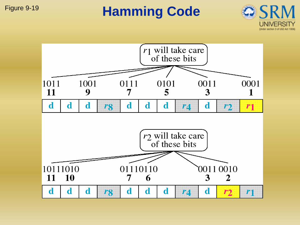
Figure 9-19 Hamming Code

Figure 9-19-continued Hamming Code

Figure 9-20 Example of Hamming Code

Single-bit error
Figure 9-21

Figure 9-22
Error Detection

Checksum
• Sender1.The checksum generator subdivides the dataunit into equal segments of n bits
2.These bits are added together using onescomplement
3.The total is then complemented and appendedto the end of the original data unit asredundancy bits called the checksum field

Checksum
• Receiver:
1. Subdivides the data unit and adds allsegments together and complements theresult
2. If the checksum field is zero then it accepts,else the receiver rejects it

Disclaimer
The contents of the slides are solely for the purpose of teaching students at SRM University. All copyrights and Trademarks of organizations/persons apply even if not specified explicitly.
8/22/2011School of Computing, Department 135

Review questions
• 1. What is the difference between Circuit Switchingand Packet Switching?
• 2. List the methods of framing
• 3. Define Bit stuffing
• 4. Define Piggybacking
• 5. What is the advantage of selective repeat ARQ overGoback‐N ARQ?
• 6. List the types of frames in HDLC
• 7. Define Unnumbered frames
• 8. List the problems in Unipolar Encoding
• 9. Define link configuration in HDLC
• 10. Define Stop and Wait ARQ
8/22/2011School of Computing, Department 136

bibliography
• 1. Andrew S. Tanenbaum, ComputerNetworks, Fourth Edition, Prentice Hall ofIndia, 2003
• 2. Cisco Network Fundamentals – CCNAExploration Companion Guide, PearsonEducation , 2008
• 3. William Stallings, Data and ComputerCommunications , Fourth Edition, PrenticeHall of India, 2004
• 4. Behrouz A.Forouzan, Data and Computer8/22/2011School of Computing, Department 137