Jewelry Illustration - Welcome to Brynmorgen Press ... · PDF fileAs a teacher of jewelry...
18
Jewelry Illustration Dominique Audette Translated by Daniel Feldstein
Transcript of Jewelry Illustration - Welcome to Brynmorgen Press ... · PDF fileAs a teacher of jewelry...

Jewelry Illustration
Dominique Audette
Translated by Daniel Feldstein
English language edition © Brynmorgen Press, Brunswick, Maine USAisbn 1-978-929565-33-7
French language edition© Centre collégial de développement de matériel didactique (CCDMD)6220, rue Sherbrooke Est, bureau 416Montréal, Québec H1N 1C1isbn 2-89470-183-7
Printed in Hong Kong
All rights reserved. No part of this publication may be reproduced or transmitted in any form or by any means, electronic or mechanical, including photocopying, recording, or any storage and retrieval system except by a reviewer who wishes to quote brief passages in connection with a review written for inclusion in a magazine, newspaper, web posting, or broadcast.

Acknowledgements
I would like to express our most sincere gratitude to the people who have helped me along the way, at one stage or another in the production of this book.
First, thank you to Micheline Boucher, Director at the École de Joaillerie de Qué-bec, who, through her involvement and constant support, made the French and English editions possible.
For having backed the English edition of this work I thank Chantale Perreault, Director of the Centre collégial de développement de matériel didactique at Collège de Maisonneuve in Montréal.
For their discerning revision of the technical content, thanks go to Catherine Villeneuve and Serge Hébert, teachers.
For the digitizing of images, Normand Saint-Cyr, graphic artist.
For the translation, which remained faithful to the original text, Daniel Feld-stein.
For the honor of his felicitous preface, Paul Bourassa, Curator at the Musée national des beaux-arts du Québec, in Québec City.
Thank you to my spouse, Mario Béland, for his unwavering support throughout the project.
Many thanks also to Avi Rachel Good for introducing us to Tim McCreight.
Lastly, a very special thank you to Tim McCreight and Abby Johnston for their professionalism, efficiency and for the lively discussions which always took place in a spirit of cordiality.
— Dominique Audette

Contents
Introduction
Chapter 1: Technical Drawing
1.1 Orthographic Projection 12
1.2 Perspective 21
1.3 The Two-Point Perspective Drawing 35
1.4 Exercises 73
Chapter 2: The Sketch
2.1 Line Exercises 75
2.2 Bands and Rings Pictured Horizontally 80
2.3 Two-Point Perspective 87
2.4 Aerial Views 134
2.5 Exercises 143
Chapter 3: Light and Shadow
3.1 Light 145
3.2 Shadow 146
3.3 Surface Finishes 174
3.4 Gradation Exercises 176
3.5 Bands Shown Horizontally 179
3.6 Bands Shown in Two-Point Perspective 191
3.7 Lights and Shadows on Selected
Forms and Surfaces 195
3.8 Exercises 207
Chapter 4: Gemstones
4.1 Cabochons 209
4.2 Spheres 217
4.3 Pearls 219
4.4 Faceted Gemstones 220
4.5 Exercises 229
Chapter 5: Gemstones Incorporated into Rings
5.1 Setting 231
5.2 Gemstone Rings Shown Horizontally 237
5.3 Gemstone Rings in Two-Point Perspective 244
5.4 Sketched Aerial Views 252
5.5 Irregular Junctions 255
5.6 Exercises 256
Chapter 6: Earrings, Pendants, Necklaces,
and Other Pieces
6.1 Mirror Symmetry 258
6.2 Developed Views 260
6.3 Earrings 262
6.4 Brooches 264
6.5 Chains 266
6.6 Pendants 268
6.7 Bracelets 270
6.8 Necklaces 273
6.9 Closures 284
6.10 Exercises 285
Chapter 7: Anatomic Form in Jewelry Presentation
7.1 Hand 287
7.2 Hand and Wrist 287
7.3 Ear and Wrist 288
7.4 Ear and Neck 289
7.5 Neck and Ear Seen from the Front 290
7.6 Neck and Ear Seen from the Side 291
Appendix 292

Foreword to the French Language Edition
The Line of Apelles and the “O” of Giotto
Many are the artistic legends recounted by the chroniclers of classical antiquity and the renaissance. Pliny the Elder, for example, told of the challenge issued by the Greek painter Apelles to his rival Protogenes. Apelles, visiting Proto-genes’s studio and finding him away, picked up a brush and drew an extremely fine line across a panel. On his return, Protogenes realized that such perfection could only be the work of Apelles, and in answer, drew an even finer line over the first in another colour. Finally, Apelles, using another colour, split both of the previous lines by drawing a line so fine that it precluded any further attempts by Protogenes, who was forced to concede defeat. Writing more than one thou-sand years later, Giorgio Vasari recounted how the painter Giotto, responding to a request from the Pope’s messenger for a sample of his work, «took a sheet of paper and a brush dipped in red, closed his arm to his side, so as to make a sort of compass of it, and then with a twist of his hand drew such a perfect circle that it was a marvel to see.» The messenger asked if this was the only drawing he was to be given, to which Giotto declared: «it’s more than enough.» When the Pope was told of the circumstances under which the drawing was executed, he was struck with amazement. Both of these stories attest to the precision of a drawing as a manifestation of talent. Ultimately, the line circumscribes the form, while at the same time, it is light and incorporeal, and therefore, borders on invisible. It is also captivating in its perfection. The line is also the architectonic principle in painting, as for-mulated by Leon Battista Alberti in his Della pittura (1436). Alberti, endeavour-ing to explain how objects are represented, postulated that circumscription reg-isters the outline of the form in space, composition shows how its surfaces and planes are combined to create a structure, and the reception of light, defines the qualities given to the drawing through the addition of lights and shadows. In this masterly treatise on jewelry illustration, Dominique Audette follows this same path. And to call it a treatise is no exaggeration, since it systemati-cally covers all aspects of the discipline, from the basic concepts of technical drawing, to their application to various types of jewelry through selected exam-ples, to a series of exercises designed to reinforce the subject matter. While not a substitute for your own inspiration or creative spark, this book is a remarkable and powerful tool that will help you express your ideas on paper. To borrow from Boileau, we might say: what is clearly conceived can be clearly drawn, and the lines with which to describe it come with ease. As a teacher of jewelry making, and particulry jewelry illustration for over twenty years, Dominique Audette was quick to realize that a manual of this type was long overdue. It re-elevates technique to its noble status as a revealer of knowledge, reminding us of the true meaning of the Greek techne. And while some of its plates reflect the art of the geometer, others are clearly the province of the painter. Bridging the gap between them, Dominique Audette retraces the path forged by the humanists of the Renaissance.
Paul BourassaCurator of Exhibitions and Director of Development Architecture, Decorative Arts, Design and Fine Crafts Musée national des beaux-arts du Québec
Foreword to the English Language Edition
In the Renaissance, it was typical for an artist's training to include goldsmith-ing. Cellini, Donatello, Brunelleschi, and Ghiberti all used the compact realm of jewelry and ceremonial objects to develop their understanding of structure, harmony, and ornament. We know this because of the drawings they left be-hind—luscious complicated designs of vines and goddesses, far removed from our modern tastes but wonderful to see all the same. Even with the advent of computer rendering technology and 500 years of industrial development, the wisdom of the Renaissance remains. There is something special, something important and potent that happens when a hu-man hand moves a pencil across a paper. This book celebrates the timeless magic of illustration as it generously yields its techniques. There are people who have a natural ability to draw "so things look real." They will find in these pages the geometric logic that lifts their intuitive skills to new levels of precision. And there are those whose boxes fall flat and whose spheres refuse to fill a genuine space. They will be thrilled with the systematic instruction found here. It can be said with confidence that nothing in this book is beyond the reach of a dedicated student. The instructions are that good. Turn the pages and you will see lovely drawings. Rings take shape and lift off the pages; gems sparkle, and necklaces lay gracefully around a neck. As wonderful as these drawings are, the importance of this book lies in the power it offers to breathe life into designs of your own imagination. Magic indeed!
Tim McCreightTeacher, designer, jeweler

Introduction
The drawing method I teach consists of a collection of recognized techniques adapted to the illustration of jewelry. Whether applied to technical drawing with instruments, orthographic projection, two-point perspective, freehand drawing, the use of light and shadow or rendering gemstones, it can be re-duced to a logically presented series of three-dimensional geometric figures. It is up to each reader to make decisions about which technique to use, and whether to use instruments or to opt for freehand work based on the purpose of the drawing. These purposes could include developing original designs, pre-paring an object for production, or creating a file of ideas, sharing them with a colleague or presenting them to a client. Each chapter presents fundamental concepts and applies them to jewelry illustration through a series of drawing exercises that exemplify particular de-sign challenges. These examples constitute a selection of basic structures and finishes that can be modified, combined, enhanced or elaborated to create original pieces. I begin with a presentation of technical drawing, essential here since the concepts it covers will be revisited in every chapter. This is followed by a dis-cussion of sketching, in which the concepts of technical drawing are adapted to quick, freehand rendering. Light and shadow will then be used to help suggest volume, relief, and finishes. I then turn to the illustration of gemstones, initially alone, and then as part of rings. In the next section, I examine the illustration of pieces other than rings, viewed from both front and top, and we conclude with a brief survey of the media used to display the jewelry piece. We place particular emphasis on rings, since the pronounced camber of the shank (i.e., its curves and arches) significantly alters the decorative pattern, making rings the most difficult type of jewelry to draw. Once the illustration of rings is mastered, it is a simple matter to draw any other type of jewelry. The illustration of each model is explained in a detailed, step-by-step pro-cedure. Because of the increasing difficulty of the exercises and the frequent references to concepts presented earlier in the book, I suggest covering the chapters in the order they appear. A list of materials required to create the drawings is provided at the begin-ning of each chapter, with a complete list as an appendix.
This chapter is divided into three sections. The first, which will be revisited in every later chapter, covers orthographic projection. The second deals with perspective drawing, and the third covers the perspective drawing developed from the orthographic projection. Certain aspects of conventional orthographic projection are used to isolate the views of an object and will be adapted to suit the type of perspective used in this book. The discussion of perspective drawing will introduce vanishing lines and our perception of the object’s location in space and lay the foundation for sketching in Chapter 2. The process of developing the perspective drawing from the orthographic projection will also be adapted to the requirements spe-cific to this field, and shortcuts will be introduced to streamline the procedures.
chapter one
Technical Drawing
MaterialsWhite multi-purpose paperTracing paper2H and 4H graphite pencilsDrawing instruments
technical drawing 11

1.1 ORTHOGRAPHIC PROJECTION
is a valuable tool for creating a free-hand drawing, providing information about the design, and, regarding the application of lights and shadows, helping to visualize how the light rays strike. This method is governed by strict conventions regarding aspects such as the layout of the views on the page, the depiction of dimensions, and line appearance. For example, dimen-sioning data are displayed adjacent to each view and a title box is placed at the edge of the page. These con-cepts, while important to the drafts-man, are beyond the scope of this book because for our purposes, the orthographic views will only be used as reference drawings in order to de-velop a model in adapted, two-point perspective. While these conventions are not important here, precision and accuracy are.
Orthographic projection (from the Greek orthos, meaning straight, and graphia, meaning writing) is a meth-od of technical drawing by means of which an exact reproduction of any object can be created. In this meth-od, the object is depicted in sepa-rate views in different orientations, the number varying with the object’s complexity, including the top view, front view, and side view. The object is depicted using its actual dimensions and it may – and under some circum-stances must – be drawn to scale. The orthographic projection of a jewelry piece helps to evaluate the workability of the object by conveying the forms of the components and their precise dimensions. This technique is also an essential basis for technical drawing in two-point perspective. Moreover, the orthographic projection
12 chapter one
1.1.1 The Glass Box
To show how the object is projected onto different planes, we use a con-cept known as the glass box (Figure 1). Imagine the object inside a trans-parent cube, with its main faces par-allel to the cube’s faces. With each of the faces visible through the cube, the object’s contours can be replicated on the corresponding cube faces by projecting them outward at 90°. This cube can then be folded out flat along its edges, revealing the individual basic views of the object. This is an orthographic projection. In jewelry illustration, three regu-
lar views – the top view, the front view and the side view—are generally used. For our purposes, they are used to develop the design into a two-point perspective drawing, to obtain infor-mation as a prelude to the sketch, or to position lights and shadows. There-fore, the process of constructing the views and the relationships between them must be clearly understood. The correct positioning of the object (here, the ring) in the cube is important, since the faces that will constitute the orthographic projection must be vis-ible.
TOP
SIDEFRONT
Fig. 1

1.1.2 Regular Views of the Object
The three most common views are known as the regular views. They are shown here in on the cube faces to clearly convey the relationships be-tween them (Figure 2). This practice will be omitted from this point on.
top view
The top view is the depiction of the ob-ject (in this illustration, a ring) as it ap-pears from above. As with all views, it must be drawn to exact proportions.
Fig.2
front view
The front view or elevation of the ob-ject.
side view
The side view can depict the object’s left side, its right side, or both. The outlines of all three views are inter-related.
To ensure a high level of precision in this method, all lines should be cre-ated using drawing instruments such as a ruler and compass. Before beginning to draw the ring, all of its dimensions must be de-termined, including:
– The finger diameter, which cor-responds to the inside diameter of the shank.
– The thickness of the shank, which, combined with the finger diameter, equals the shank’s outside diam-eter.
1.1.3 Construction of an Orthographic Projection
– The width of the ring. This corre-sponds to the width of the shank, and, if any, the ornamental ele-ments.
– The dimensions of the ornamen-tal elements or gemstones (height, length, width).
– The scale of the drawing. The ob-ject can be drawn to actual size or to a reduced or enlarged scale. For two-point perspective, we advise not exceeding a scale of two-to-one (written as 2:1). This means that the ring may be depicted at up to twice its actual size.
technical drawing 13
FRONTSIDE
TOP

Fig. 3
The three views will be drawn con-currently and will be interconnected by lines known as projectors. These lines show the relationships between the faces in the different views. The projectors are always perpendicular to the projection faces and parallel to one another. For the sake of efficiency and clarity, all construction lines, including centerlines and projectors, will be drawn lightly using the 4H pencil, while the model itself will be rendered in a darker line with the 2H pencil.
preparatory steps
• Visualizetheringinsideaglassbox, positioned according to the desired angle. For our purposes, the left face should be visible. A quick sketch may be required to do this.
•Determinethescaleofthedraw-ing.
• Calculatethescaledimensions.• Affixthepagehorizontallytothe
drawing table, using the parallel rule or T-square to align it.
•Evaluatethecombineddimen-sions of the views and lay them out correctly on the page using vertical and horizontal centerlines. The intersections of the centerlines serve as references for positioning the views and, in the case of a ring, centering the finger hole on the front view. We suggest a distance of four to five centimeters between the centerlines. This distance leaves enough space to depict the ring at a 2:1 scale, at which the piece’s decorative elements are clearly discernable.
1.1.3.1 Front View (Fig. 3)– Draw the inner shank. Using a com-
pass with its point at the intersection of the centerlines on the lower right, draw a full circle that is the diam-eter of the finger. In this illustration, the vertical centerline on the left is not yet present.
– Draw the outside curve of the shank. With the compass point on the same intersection, draw a semicircle be-low the horizontal centerline and place a mark on the vertical center-line at the same distance above the horizontal centerline as the semicir-cle travels below it. The diameter of the semicircle is equal to the finger diameter plus twice the thickness of the shank (the left and right sides).
– Construct the sides of the ring us-ing two verticals that extend from the meeting points of the semicircle and the horizontal centerline on the front view to where they meet the horizontal centerline on the top view.
– Project the diameter of the inner shank in similar fashion.
1.1.3.2 Top View (Fig. 4)The projectors from the shank’s out-side and inside curves on the front view govern the placement of its cor-responding edges on the top view.The outside edges are illustrated us-ing a solid line, while the edges of the inside curve are illustrated using a dashed line. By convention, all invis-ible lines in an orthographic projec-tion are depicted in this manner. They play a valuable role in conveying the relationships between the figures in the different views. Note, however, that these hidden lines depict different elements from one view to another.
– Define the width of the ring using two horizontals placed equidis-tantly from the horizontal centerline on opposite sides.
– Define the edges of the ornamental element using two verticals equi-distant from the vertical centerline on opposite sides of it.
14 chapter one

on the front view
– Define the height of the ring’s flat top with a horizontal line. Here, its height is established by the mark previously placed on the vertical centerline. This mark was created in the same step as the semicircle depicting the outside of the shank.
– Project the edges of the ornamental element from the top view down.
– Define the height of the ornament and draw a horizontal line for its top.
Fig. 5
technical drawing 15
1.1.3.3 Side ViewOften, the layout of the side view stems directly from those of the other two views. The projectors from the top view intersect those from the front view to define the contours of the side view, as shown in Figure 5. In this case, the side view is con-structed on the left vertical centerline, meaning the illustration will show the left side of the ring. This is preferable to the right side, since, when illustrat-ing a ring in perspective, the piece is most often shown with its left side vis-ible, allowing for a dynamic move-ment toward the upper right.
– Draw a 45º segment through the meeting point of the left vertical centerline and the top horizontal centerline.
– From the top view, project hori-zontals from each of the elements. These horizontal projectors pivot at the 45º segment and drop as verticals to the side view. Using this method, the projectors from the top view can be redirected 90º to-ward the side view with no need to change the spacing between them.
– From the front view, project hori-zontals to the side view from each of the elements, including hidden lines. The meeting points of the horizontals from the front view and the verticals from the top view de-fine the side view. The three views are very closely interrelated. To de-fine a side view, projectors from the top view and the front view must be projected together. In some cases, elements from the side view can also be projected to the other views to obtain missing information.
– Redraw the contours using a darker line.
Fig. 4
16 chapter one
1.1.4 Illustration of Basic Designs
In the illustrations that follow, you will see that orthographic projections are created to assist in creating the per-spective view. This is why the top, front and side views, as well as any form other than square or rectangu-lar, are always inscribed in quadrilat-erals. Moreover, the square isolating the outer shank on the front view is subdivided by diagonals. Later, these diagonals will be used to position the circle in perspective. This step is not necessary when the aim is to create an orthographic projection and noth-ing more. Here, however, the three views are not an end in themselves, but rather a tool used to illustrate an object in two-point perspective. There-fore, these construction lines must be added.
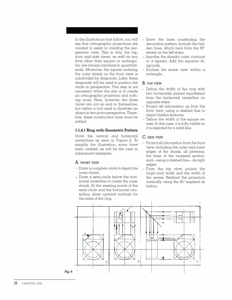
1.1.4.1 Ring with Geometric PatternDraw the vertical and horizontal centerlines as seen in Figure 6. To simplify the illustration, some have been omitted, as will be the case in subsequent examples.
a. front view
– Draw a complete circle to depict the inner shank.
– Draw a semi-circle below the hori-zontal centerline to create the outer shank. At the meeting points of the semi-circle and the horizontal cen-terline, draw upward verticals for the sides of the ring.
– Draw the lines constituting the decorative pattern. Include the hid-den lines, which here form the 90° recess on the left slope.
– Inscribe the shank’s outer contours in a square. Add the square’s di-agonals.
– Enclose the entire view within a rectangle.
B. top view
– Define the width of the ring with two horizontals placed equidistant from the horizontal centerline on opposite sides.
– Project all information up from the front view, using a dashed line to depict hidden features.
– Define the width of the square re-cess. In this case, it is fully visible so it is depicted by a solid line.
c. side view
– Project all information from the front view, including the outer and inner edges of the shank, all plateaus, the base of the recessed section, and—using a dashed line—its right edges.
– From the top view, project the ring’s total width and the width of the recess. Redirect the projectors vertically, using the 45° segment as before.
A CB
Fig. 6
technical drawing 17
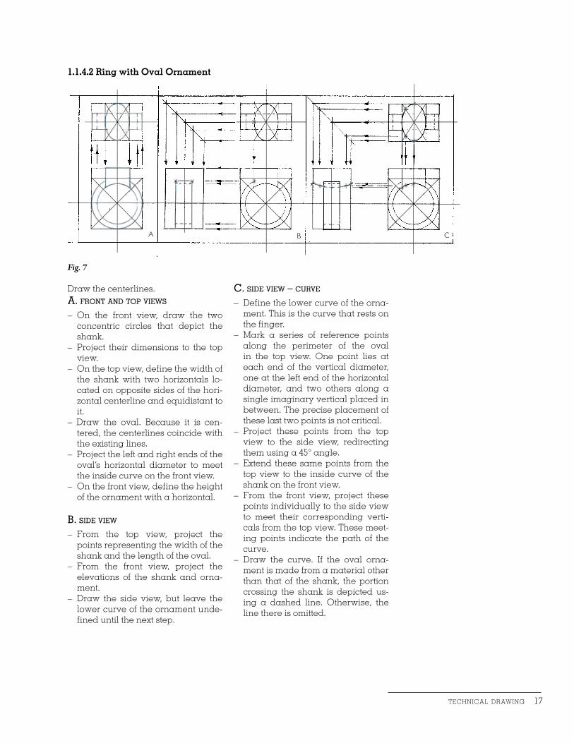
Draw the centerlines.a. front and top views
– On the front view, draw the two concentric circles that depict the shank.
– Project their dimensions to the top view.
– On the top view, define the width of the shank with two horizontals lo-cated on opposite sides of the hori-zontal centerline and equidistant to it.
– Draw the oval. Because it is cen-tered, the centerlines coincide with the existing lines.
– Project the left and right ends of the oval’s horizontal diameter to meet the inside curve on the front view.
– On the front view, define the height of the ornament with a horizontal.
B. side view
– From the top view, project the points representing the width of the shank and the length of the oval.
– From the front view, project the elevations of the shank and orna-ment.
– Draw the side view, but leave the lower curve of the ornament unde-fined until the next step.
1.1.4.2 Ring with Oval Ornament
c. side view – curve
– Define the lower curve of the orna-ment. This is the curve that rests on the finger.
– Mark a series of reference points along the perimeter of the oval in the top view. One point lies at each end of the vertical diameter, one at the left end of the horizontal diameter, and two others along a single imaginary vertical placed in between. The precise placement of these last two points is not critical.
– Project these points from the top view to the side view, redirecting them using a 45° angle.
– Extend these same points from the top view to the inside curve of the shank on the front view.
– From the front view, project these points individually to the side view to meet their corresponding verti-cals from the top view. These meet-ing points indicate the path of the curve.
– Draw the curve. If the oval orna-ment is made from a material other than that of the shank, the portion crossing the shank is depicted us-ing a dashed line. Otherwise, the line there is omitted.
A CB
Fig. 7

18 chapter one
a. front view
– Draw the centerlines.– Draw the front view. Because the
ring consists entirely of round wire, hidden wire ends and cross-sec-tions are depicted by dashed lines. Here, the donut shown in the ring’s top view occupies 60 degrees of the shank’s circumference. It is defined by two segments originating at the intersection of the centerlines.
B. top view
– Project all dimensions to the top view, using dashed lines to depict the portion of the shank covered by the donut. The shank’s width is equal to the diameter of the round wire.
Fig. 8
A CB
1.1.4.3 Ring in Round Wire
c. side view
– Project all dimensions from the top view to the side view, redirecting them at the 45º segment.
– Establish the meeting points of cor-responding projectors from the top and front views in order to com-pletely define the side view. Note that all ends are rounded.

technical drawing 19
a. top and front views
– Draw the centerlines.– On the top view, establish the
shank’s width and outside diam-eter.
– Place a mark on the vertical center-line and connect it to the shank with two symmetrical curves.
– Project all dimensions, in this case the outside diameter and the tip of the arrowhead, to the front view.
– On the front view, draw the shank’s inner circle and outer semi-circle.
– Define the height of the sides and connect their endpoints with the curve depicting the top of the ring.
– Project the dimensions of the inner circle to the top view.
B. side view – outer curve
– On the top view, mark a number of reference points on the curve to define its path.
– Project these points to the side view by means of the 45º segment.
– From the top view, extend these same points down to the outside curve on the front view.
– From the front view, project these points individually to the side view to meet their corresponding projec-tors from the top view. These meet-ing points indicate the path of the curve.
1.1.4.4 Ring with Arrowhead Projection
c. side view – inner curve
– Repeat the above operation using the same points on the top view, but extend them down to the inside curve on the front view.
– Also define the tip of the arrowhead at the end of the curve.
Fig. 9
A CB

20 chapter one
1.1.4.5 Tapered RingIn some cases, it may be preferable to construct the side view before con-structing the top view. Because its sides are angled obliquely, on the top view the tapered shank appears as a series of ellipses. To determine the angle of these ellipses, the width of the ring at the top and base must first be determined. This information will be used to define rectangles which will frame the ellipses on the top view. Because the side view best reveals the width of the ring, it will be constructed first (Figure 10).
A. Front and Side Views
– Draw the centerlines. – Begin by drawing the front view
which will consist of two concentric circles.
– Draw the side view based on the dimensions projected from the front view. These consist of the ring’s overall height and the inner diam-eter of the shank.
– Determine the width of the ring at the top and the base.
B. Top View
– Project the dimensions from the front view, in this case, the inner and outer curves of the shank.
– Project the dimensions from the side view, redirecting them at the 45º segment. Begin by projecting the width of the shank at the top and base. These lines create rectangles used to define two large ellipses on the top view. Since the lower half of each ellipse is hidden from view, it is depicted by a dashed line. Now project the shank’s inner diameter at the top and base. These dimen-sions are entirely depicted by a dashed line.
– To properly orient the ellipses, it can be helpful to find their horizon-tal axes. To do this, run projectors to the top view from meeting points of the ring’s sides and horizontal centerline on the side view. They also happen to coincide with the rectangles’ horizontal centerlines on the top view.
Fig. 10