JETFAN€¦ · · 2018-03-13BS 7346-7. B- PRESSURE LOSS Pressure losses caused by shafts,...
24
PARKING VENTILATION AND SMOKE EXHAUST SYSTEMS JETFAN www.fanturk.com.tr
Transcript of JETFAN€¦ · · 2018-03-13BS 7346-7. B- PRESSURE LOSS Pressure losses caused by shafts,...

PARKING VENTILATION AND
SMOKE EXHAUST SYSTEMS
JETFAN
www.fanturk.com.tr

MISSION
Ofering innovative technologies to the beneit of humanity.
VISION
To become a leading enterprise globally by producing
technologies that help humanity to breathe.

%75*75% of the casualties in ire cases occur due to smoke inhalation.
Therefore, exhausting the smoke in enclosed areas with the risk of ire are vital.

-----------------------------------------------------------------------------------------------------------------------------------------
Competencies Of The System
Advantages for the investors•Reduces costs by replacing bulky and complex duct systems. It is particularly advantageous for renovation projects.
•Modern aesthetics: Flexible positioning of Jet Fans facilitate modern and aesthetic de-
signing.
•Sleek and regular design: Unlike ductworks the system is more sightly as a whole and cause no obstacles in sight.
Advantages and beneits for planners
•Whether used in new buildings or renova-
tions projects they provide signiicantly lexible positioning.
•There is no need for complex ductworks.
The advantages and beneits for the parking operators;
•Easy to install: Jet fans can be mounted quickly and easily on the roof.
•Hassle-free setup: Mounting the fans may be the inal step of a project which means less overlap with other works.
•Flexible positioning.
The advantages and beneits to the operator•Energy eicient Jet Fan System. Cuts the costs signiicantly by saving energy up to %80. Energy eiciency is facilitated by the smart control unit which is the main focus of the system to control the air movements de-
pending on the alternative needs of the medium.
Unlike duct systems, pressure droppings does not occur in jet fan systems allowing them to operate with a low level of power which means another way of energy saving.
•Customized according to needs: The carbon monoxide (CO) sensor switches the fans on only in the needed areas and only when the need occurs. Predeined areas can be ven-
tilated without employing the whole fans in the system. This feature also helps to reduce the operating costs.
•High air quality: During Jet Fan operation the concentration of the air pollutants re-
main much lower than during the operation of duct systems. During the operation of the fans the air remains in a constant motion which helps the rate of fresh air to increase in all areas in the medium.
•Evacuating the heat and the smoke quickly, Jet Fan Systems prevent costly damages in the ceilings reducing the level and the dura-
tion of temperature they are exposed to.
•Sensitive smoke control, provides optimum safety in the event of a ire and make the ire department’s job easier as Jet Fans evacuate the smoke and the heat rapidly before they spread to other areas of the building.

---------------------------------------------------------------------------------------------------------------------------------------------------------------
Calculation Steps For Jet Fans1-CALCULATION OF VOLUME
V = A . h
Where V is the volume, A is the area and h is the height of
the building,
Area = Width x Depth = 40 m x 100 m = 4000 m2
Height = 3 m Volume = 4000 m2 x 3 m = 12000 m3
2-AIR FLOW CALCULATION
Q = V . Ach
Where Q is the Flow, V is the Volume and Ach is the coei-
cient of the air exchange,
a) Daily carbon monoxide (CO) ventilaiton air low,
Ach = 6 times/h,
V = 12000 m3,
Q = 12000 . 6 = 72000 m3/h,
b) Fire event ventilation air low,
Ach = 10 times/h,
V = 12000 m3,
Q = 12000 . 10 = 120000 m3/h
* Minimum Ach value is obtained from BS 7346-7 standards.
Depending on the architectural details higher air eXchange
coeicient values can taken for car parks.
3-FAN SELECTION FOR EXHAUST AND FRESH AIR
VENTILATIONS
A – AIR FLOW
Exhaust Fan (DEF)
DEF = 120000 m3/h x %50 = 60000 m3/h
DEF – 1 = 60000 m3/h DEF – 2 = 60000 m3/h
*The exhaust air low is backed up %50 in accordance with
BS 7346-7.
B- PRESSURE LOSS
Pressure losses caused by shafts, silencers, dampers or lou-
vers are determined by the air speed.
C- FIRE RESISTANCE
Exhoust and jet fans are selected in comliance with TS/EN
12101-3 ire resistance standard.
Fresh Air Fan (THF)
THF = 120.000 m3/h x %60 = 72.000 m3/h
50% - 70% of the exhaust air fans are Flows Considered as the air
low for the fresh air fans.
4- Considering the height of the ceiling and the length of the building jet fans with optimal thrust are slected. Radial jet fans are preferred in one-way operations as they have height advantages.
5- SHAFT SIZING
According to the Air VelocityThe shaft sizes should be calculated as such that the maximum velocity of the air that should pass through the shaft area must be 8 m/sec.
72000 m3/h = 20 m3/sShaft Area=(Air Flow )/Velocity =(20 m3/s)/(8 m/s) =2,5 m2
According to the Fan SizeWhen fans are installed inside the shafts the fan size also must be cosidered, giving priority to the cross-section air velocity.
6- SHAFT DAMPER SIZING
Corresponding to each fan given the air velocity as 8 m/sec a motorized shaft smoke exhaust damper, which facilitates zoning between loors, is selected.
Example:8 m/sec = 28800 m/hIf 2 shafts are to be selected then the Airf Flow for each shft would be 72000 m3/h = 36000 m3/h + 36000 m3/h
Efective Area=(Air Flow )/Velocity =(36000 m3/h)/(28800 m/h) =1,25 m2
7- CFD ANALYSIS
When designing the system all problems that involve the low of the air are analyzed and solved using com-
puter simulation and CFD analysis method.

JETFANS
GENERAL FEATURES
The hardware used in smoke exhaust fans are tested and ceriied to the internaionally recognized AMCA/ANSI standards.
High temperature FTAJF models’ equipments are ire ceriied by internaionally recog-
nized accreditaion organizaions.
Jefans are produced between the diameter ranges of Ø315 mm and Ø560 mm. Depending on the applicaion the fan can be produced as unidirecional or reversible and as suitable for tow speed or variable speed operaions.
THE BODY OF THE FAN
TFAJF type fan’s cassete body is manufactured from ST37 (S235JR) (EN10025) quality steel and all steel parts are protected with polyester powder coaing and hot dipped galvanized casing opionally.
IMPELLER
Adjustable body pitch aerofoil impellers manufactured from special aluminum alloy under internaional standards.
ELECTRIC MOTOR
Three-phase 380V - 50Hz (standard), 400/415/440 V - 50 Hz and manufactured on demand in other voltage and frequencies as well. Class H, S1, IP55 motors are used as standard.
ACCESSORIES
Silencers are used in these series to reduce the noise created by the guide vanes ixed to the body for the purpose of speeding up the air supplied.

TECHNICAL PROPERTIES
DRAWINGS

FTAJF-315A
CHARTS
FTAJF-355A

Smoke ExhaustFIRE PROTECTION
REGULATIONS OF
THE BUILDINGS
2007 REQUIRE THE
PARKINGS WITH
2000 m2 AREA OR
ABOVE TO HAVE
MECHANICAL
SMOKE EXHAUST
SYSTEM WITH THE
SMOKE EXTRAC-
TION CAPACITY
OF 10 TIMES PER
HOUR. THERE IS
MORE INFORMA-
TION ABOUT THE
SUBJECT IN BS
7346-7 STANDARD.
FTAJF-400A
FTAJF-450A

FTAJF-500A
FTAJF-560A

INDOOR PARKINGSWith Clean Air

There are axial and/or radial types of Jetfan Systems each with diferent power options.
Jetfans are positioned in a parking as parallel and series, in intervals the distances of whom de-
pend on their thrust and the features of the models, to cover all areas and avoid dead zones in
the parking. The interval distances may also vary according to the architectural structure of the
building.
The thrust Jetfans generate help mobilize large masses of air to reduce levels of CO and other
harmful air pollutants and to assist with the extraction of smoke in the event of a ire.
Jetfans restrict the distribution of smoke and toxic gasses only to the ire region guiding the
smoke out before spreading to other areas.
Once the smoke and the heat is reduced and directed to an exit, the visibility of the ireighters
will be improved and the ire point can be approached as close as 10 meters.
OPERATING PRINCIPLE OF THE JET

Helping humanity to breathe

Considering the volume of the air, the shape and the size of the pariking area and the positions of the shafts in the building the selection and sequencing of the jet fans are designed.
An emergency planning would support the selection of the fans in the project using Computational Fluid Dynamics Analisis which will help us obtain prelimi-nary information simulating all possible emergency
scenaios, form a probable ire event to the evacuation of the exhaust gases, to ind out alternative solutions for the exhaustion of unwanted gases.
To determine the accuracy of Jet fan ventilation system design and to achieve precise positioning of the Jet fans it is necessary to ceate a 3D model and luid dynamics simulation of the parking under a set of given conditions.
Simulation must be designed by means of an internationally recognized softwa-
re such as CFX or CFDesign. As a result it should determine the number and the optimized positions of the Jet fans.
Design
CFD Analizi

Positions of the Fans
Introduction

The analysis under a ire event scenario
This study should reveal;- The air low details of the parking,- Air velocity proiles,- The smoke dispersion behaviours.
- Ceiling level smoke density, visibility and air movements,
- Smoke density at 1.5 m high above the loor, visibility and air movements,
- The temperature distribution inside the parking lot during the ire event,
- Air low detail that will occur in the parking lot,
- Air velocity proiles.
Jet Fans level simulation result

Activation and Delivery
For the daily ventilation states the following analysis should be done:- The distribution of the air velocity and the air movement 0,5 m above the loor,- The distribution of the air velocity and the air movement 1,5 m above the loor,- The distribution of the air velocity and the air movement 2,0 m above the loor,- The air low detail that will occur in the parking lot,- The air velocity proiles.
All electrical data, currency consumption values at diferent speed levels, sound levels, air low rates shall be measured and presented in a report.
The software must be tested on the control panel and according to the site measurements the necessary settings/revisions must be carried out.
The system scenario is checked for, and adjusted if needed to, the reality.The system’s functionality must be checked for the diferent loors and zones by means of cold smoke testing.
All results must be presented in a report.
The simulation results in the human level
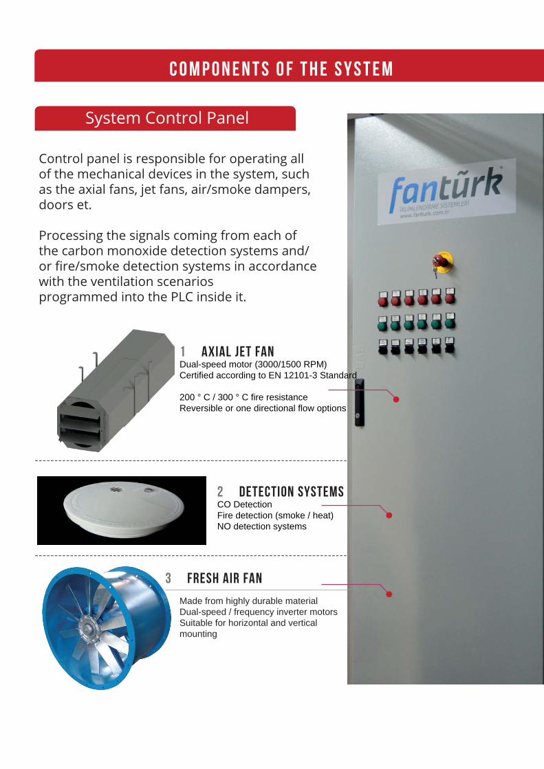
1 AXIAL JET FANDual-speed motor (3000/1500 RPM)
Certiied according to EN 12101-3 Standard
200 ° C / 300 ° C ire resistanceReversible or one directional low options
C O M P O N E N T S O F T H E S Y S T E M
--------------------------------------------------------------------------------
2 DETECTION SYSTEMSCO Detection
Fire detection (smoke / heat)
NO detection systems
System Control Panel
Control panel is responsible for operating all of the mechanical devices in the system, such as the axial fans, jet fans, air/smoke dampers, doors et.
Processing the signals coming from each of the carbon monoxide detection systems and/or ire/smoke detection systems in accordance with the ventilation scenarios programmed into the PLC inside it.
--------------------------------------------------------------------------------
Made from highly durable material
Dual-speed / frequency inverter motors
Suitable for horizontal and vertical
mounting
3 FRESH AIR FAN

4 RADIAL JET FANSDual-speed motor (1500/1000 RPM)
Certiied according to EN 12101-3
Standard
300 °C resistance for 2 hours
High air velocity rate
6 FIRE AND SMOKE EXHAUST FANS
5 REVERSE FLOW DAMPER
Made of galvanized steel
Unidirectional airlowPrevents the risk of by-pass
Motorized / non-motorized types
-----------------------------------------------------------------------------------
---------------------------------------------------------------------------------
Wall mounted, roof type and duct type options are
available.
• 250 °C 300 °C 400 °C heat resistence up to 1-2 hours
depending on the project.
• Manufactured between Ø 350 mm -1250 mm diameter ranges.
• Single or double-speed motors option.


SOME REFERENCES
Axial Jefans 12 Pcs.Axial Fresh Air Fan 1 Pcs.Smoke Exhaust Fan 4 Pcs.System Control PanelSmoke Dampers
CORNER PLUS PLAZA BURSA
Radial Jefans 34 Pcs.Axial Fresh Air Fan 4 Pcs.Axial Smoke Exhaust Fan 4 Pcs.System Control PanelSmoke Dampers
OSMANGAZi DOGANBEY STOREY CAR PARK
Axial Reversible Jefans 12 Pcs.Radial Jefans 31 Pcs.Axial Smoke Exhaust Fan 8 Pcs.System Control PanelSmoke Dampers
Axial Jefans 10 Pcs.Axial Smoke Exhaust Fan 5 Pcs.System Control PanelSmoke Dampers
BAKYAPI İSTANBUL PRESTİJ INDOOR PARKİNG LOT
BANDIRMA BELEDİYESİ BAZAR AREA PARKİNG

FAN İKLİMLENDİRME SOĞUTMABACA METAL ISITMA SOĞUTMA SAN. TİC. LTD. ŞTİ.NOSAB 202. Sk. No:19 Nilüfer / Bursa
Tel: 0(224) 482 29 69 Fax: 0(224)482 50 96E-mail: [email protected]

HELPING THE HUMANITY TO BREATHE,
PARKING LOT VENTILATION AND
SMOKE EXHAUST SYSTEMS
NOSAB 202. Sk. No:19 Nilüfer / Bursa
Tel: 0(224) 482 29 69 Fax: 0(224)482 50 96
E-mail: [email protected]
www.fanturk.com.tr
Design
about.me/muratduman