
Domestic Water Heating and Water Heater Energy Consumption in Canada

Section 1000Bulletin 1400
Issued 6/87Replaces 6/85
PENBERTHYJET PUMP TECHNICAL DATA
heatingliquidsThis technical bulleting includes general informationabout Penberthy Steam Jet Heaters plus specific detailsfor selecting the proper unit. Two series of PenberthySteam Jet Heaters are covered in this bulleting are usedfor heating liquids in line. Four individual models areavailable for heating liquids in tanks.

2
Steam jet heaters optimize thecondensing of steam into operat-ing liquids to provide efficient fluidheating. They essentially are jetpumps, and as such, operate onthe principle of one fluid entraininga second fluid.
Steam jet heaters have threecommon features (designationsmay vary according to design):inlet, suction and discharge.
Inlet – The operating liquid (some-times called the Motive) underpressure enters the inlet and trav-els through the nozzle into thesuction chamber. The nozzleconverts the pressure of the oper-ating liquid into a high velocitystream, which emerges from thedischarge side of the inlet nozzle.
Suction – Pumping action beginswhen steam in the suction cham-ber is entrained by the high veloc-ity operating liquid stream emerg-ing from the inlet nozzle, loweringthe pressure in the suction cham-ber. The resulting action causesthe steam in the suction chamberto flow toward the discharge.
Discharge (sometimes calledOutlet) – The entrained steam nthe suction chamber mixes andcondenses into the operating liquidand acquires part of its energy,flowing into the parallel section. Inthe diffuser section, part of the
velocity of the mixture is convertedinto a pressure greater than thesuction pressure, but lower thanthe inlet pressure.
Stream jet heater operationSeveral types of Penberthy SteamJet Heaters are available. Al-though their designs vary, theoperation of each is based on thejet operating principles of the jetpump.
Typically, a steam jet heater in-cludes an inlet for the liquid to beheated, a steam inlet (suction)where steam is introduced underpressure, and a discharge wherethe heated liquid and condensedsteam leave the heater. (Thesecorrespond to the inlet, suctionand discharge of a jet pump.)Compare the cutaway illustrationof a jet pump to the illustrations ofjet heaters on these pages to helpclarify some of the similaritiesbetween jet heaters and jetpumps.
The advantages of using steamjet heaters for heating liquidsPenberthy Steam Jet Heaters offermany advantages: They have nomoving parts, nothing to break orwear.There are no packing glands.No lubrication is required.The initial cost is low.Installation cost is low becausethey are compact and no founda-tion or wiring is necessary. Theyprovide reliable operation
with low maintenance cost.
Steam jet heater applicationsThere are numerous possibleapplications for Penberthy SteamJet Heaters. Heaters are availablefor heating liquids in line or in atank. Steam Jet Heaters arecommonly found in these indus-tries: food processing, petroleum,dairy, manufacturing, chemical,distilling/brewing, and others.
Specific applications for inlineheaters include: circulating clean-ing solutions, pasteurization, pro-ducing scalding sprays, steriliza-tion, heating water, blanching,exchanging heat, degreasing,heating slurries, laundering, cook-ing, pickling, bonderizing,quenching and tempering.
Specific applications for open tankheaters include cooking grain,cooking mash, cooking starch,heating and circulating, mixing.
introduction and applications
Typical steam jet heater (or jet pump)
Typical Applications
Heating liquids in line Parts washer

3
applicationsTypical Applications (cont.)
Heating liquids in open tank with XL-32 Heater
Adding small amounts of steam to a large flow of water
Heating liquids with Circulating Tank Eductors (CTE)
Circulating hot water system
4
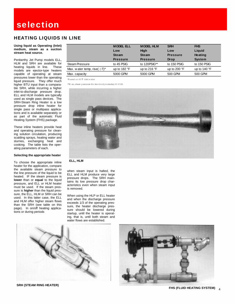
Using liquid as Operating (Inlet)medium, steam as a suctionstream heat source.
Penberthy Jet Pump models ELL,HLM and SRH are available forheating liquids in line. Thesemodels are ejector-type heaterscapable of operating at steampressures lower than the operatingliquid pressure. They offer muchhigher BTU input than a compara-ble SRH, while incurring a higherinlet-to-discharge pressure drop.ELL and HLM models are typicallyused as single pass devices. TheSRH-Steam Ring Heater is a lowpressure drop inline heater forsingle pass or multipass applica-tions and is available separately oras part of the automatic FluidHeating System (FHS) package.
These inline heaters provide heatand operating pressure for clean-ing solution circulation, producingscalding sprays, heating water andslurries, exchanging heat andcooking. The table lists the oper-ating parameters of each.
Selecting the appropriate heater
To choose the appropriate inlineheater for the application, comparethe available steam pressure tothe line pressure of the liquid to beheated. IF the steam pressure islower than or equal to the liquidpressure, and ELL or HLM heatermust be used. If the steam pres-sure is higher than the liquid pres-sure, the ELL, HLM or SRH can beused. In this latter case, the ELLand HLM offer higher steam flowsthan the SRH (see table on thispage). In on/off heating applica-tions or during periods
when steam input is halted, theELL and HLM produce very largepressure drops. The SRH main-tains its low pressure drop char-acteristics even when steam inputis removed.
When using the HLP or ELL heaterand when the discharge pressureexceeds 1/3 of the operating pres-sure, the heater discharge pres-sure should be lowered duringstartup, until the heater is operat-ing, that is, until both steam andwater flows are established.
selectionHEATING LIQUIDS IN LINE
MODEL ELLLowSteamPressure
MODEL HLMHighSteamPressure
SRHLowPressureDrop
FHSLiquidHeatingSystem
Steam Pressure to 45 PSIG to 120PSIG** to 150 PSIG to 150 PSIGMax. w ater temp, rise( DT)* up to 182 °F up to 216 °F up to 200 °F up to 140 °FMax. capacity 5000 GPM 5000 GPM 500 GPM 500 GPM*Based on 60°F inlet water
**M ax. steam pressure for iron body material, 60 PSIG
ELL, HLM
SRH (STEAM RING HEATER)FHS (FLUID HEATING SYSTEM)
5
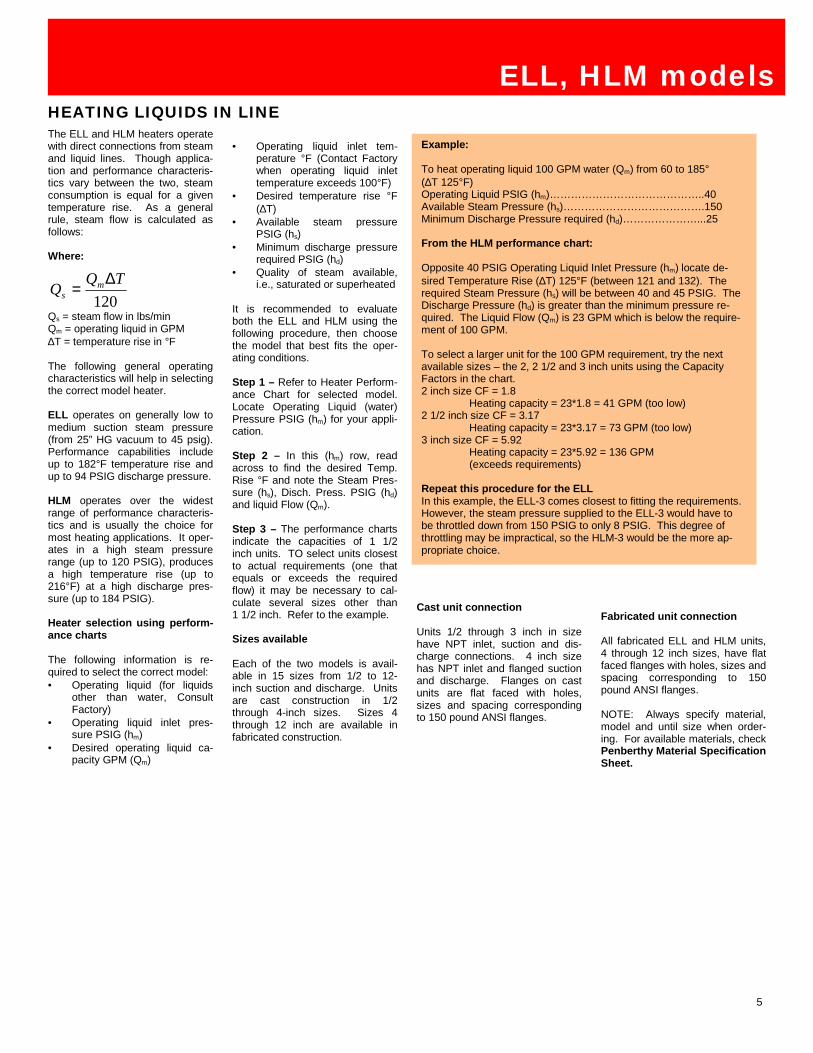
The ELL and HLM heaters operatewith direct connections from steamand liquid lines. Though applica-tion and performance characteris-tics vary between the two, steamconsumption is equal for a giventemperature rise. As a generalrule, steam flow is calculated asfollows:
Where:
Qs = steam flow in lbs/minQm = operating liquid in GPM∆T = temperature rise in °F
The following general operatingcharacteristics will help in selectingthe correct model heater.
ELL operates on generally low tomedium suction steam pressure(from 25” HG vacuum to 45 psig).Performance capabilities includeup to 182°F temperature rise andup to 94 PSIG discharge pressure.
HLM operates over the widestrange of performance characteris-tics and is usually the choice formost heating applications. It oper-ates in a high steam pressurerange (up to 120 PSIG), producesa high temperature rise (up to216°F) at a high discharge pres-sure (up to 184 PSIG).
Heater selection using perform-ance charts
The following information is re-quired to select the correct model:• Operating liquid (for liquids
other than water, ConsultFactory)
• Operating liquid inlet pres-sure PSIG (hm)
• Desired operating liquid ca-pacity GPM (Qm)
• Operating liquid inlet tem-perature °F (Contact Factorywhen operating liquid inlettemperature exceeds 100°F)
• Desired temperature rise °F(∆T)
• Available steam pressurePSIG (hs)
• Minimum discharge pressurerequired PSIG (hd)
• Quality of steam available,i.e., saturated or superheated
It is recommended to evaluateboth the ELL and HLM using thefollowing procedure, then choosethe model that best fits the oper-ating conditions.
Step 1 – Refer to Heater Perform-ance Chart for selected model.Locate Operating Liquid (water)Pressure PSIG (hm) for your appli-cation.
Step 2 – In this (hm) row, readacross to find the desired Temp.Rise °F and note the Steam Pres-sure (hs), Disch. Press. PSIG (hd)and liquid Flow (Qm).
Step 3 – The performance chartsindicate the capacities of 1 1/2inch units. TO select units closestto actual requirements (one thatequals or exceeds the requiredflow) it may be necessary to cal-culate several sizes other than1 1/2 inch. Refer to the example.
Sizes available
Each of the two models is avail-able in 15 sizes from 1/2 to 12-inch suction and discharge. Unitsare cast construction in 1/2through 4-inch sizes. Sizes 4through 12 inch are available infabricated construction.
Cast unit connection
Units 1/2 through 3 inch in sizehave NPT inlet, suction and dis-charge connections. 4 inch sizehas NPT inlet and flanged suctionand discharge. Flanges on castunits are flat faced with holes,sizes and spacing correspondingto 150 pound ANSI flanges.
Fabricated unit connection
All fabricated ELL and HLM units,4 through 12 inch sizes, have flatfaced flanges with holes, sizes andspacing corresponding to 150pound ANSI flanges.
NOTE: Always specify material,model and until size when order-ing. For available materials, checkPenberthy Material SpecificationSheet.
ELL, HLM modelsHEATING LIQUIDS IN LINE
120TQQ m
s∆
=
Example:
To heat operating liquid 100 GPM water (Qm) from 60 to 185°(∆T 125°F)Operating Liquid PSIG (hm)……………………………………..40Available Steam Pressure (hs)………………………………….150Minimum Discharge Pressure required (hd)…………………...25
From the HLM performance chart:
Opposite 40 PSIG Operating Liquid Inlet Pressure (hm) locate de-sired Temperature Rise (∆T) 125°F (between 121 and 132). Therequired Steam Pressure (hs) will be between 40 and 45 PSIG. TheDischarge Pressure (hd) is greater than the minimum pressure re-quired. The Liquid Flow (Qm) is 23 GPM which is below the require-ment of 100 GPM.
To select a larger unit for the 100 GPM requirement, try the nextavailable sizes – the 2, 2 1/2 and 3 inch units using the CapacityFactors in the chart.2 inch size CF = 1.8
Heating capacity = 23*1.8 = 41 GPM (too low)2 1/2 inch size CF = 3.17
Heating capacity = 23*3.17 = 73 GPM (too low)3 inch size CF = 5.92
Heating capacity = 23*5.92 = 136 GPM(exceeds requirements)
Repeat this procedure for the ELLIn this example, the ELL-3 comes closest to fitting the requirements.However, the steam pressure supplied to the ELL-3 would have tobe throttled down from 150 PSIG to only 8 PSIG. This degree ofthrottling may be impractical, so the HLM-3 would be the more ap-propriate choice.

6
ELL, HLM models1 1/2 MODEL ELL HEATER PERFORMANCE CHART (WATER)
1 1/2 MODEL HLM HEATER PERFORMANCE CHART (WATER)
All d
ata
base
d on
32-
100°
F op
erat
ing
liqui
d te
mpe
ratu
res.
For o
ther
tem
pera
ture
s, c
onsu
lt fa
ctor
.Al
l dat
a ba
sed
on 3
2-10
0°F
oper
atin
g liq
uid
tem
pera
ture
s.Fo
r oth
er te
mpe
ratu
res,
con
sult
fact
or.
7
ELL, HLM models
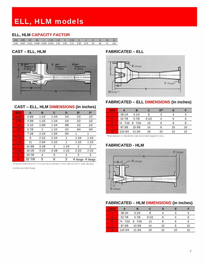
1/2A 1/2B 1/2 3/4 1 1 1/4 1 1/2 2 2 1/2 3 4 6 8 10 120.03 0.047 0.121 0.208 0.344 0.613 1.00 1.82 3.17 5.92 11.8 24 49 71 123
ELL, HLM CAPACITY FACTOR
CAST – ELL, HLM
CAST – ELL, HLM DIMENSIONS (in inches)
FABRICATED – ELL
FABRICATED – ELL DIMENSIONS (in inches)
SIZE A B C D** E F4 38 1/4 5 1/4 8 3 4 46 52 7/8 5 7/8 9 1/2 4 6 68 74 7/16 8 7/16 13 6 8 810 87 3/8 10 3/8 14 8 10 1012 110 3/4 11 3/4 18 10 12 12
**Inlet flanges on fabricate units have blind tapped holes.
(NPT-flanged on6” size*)
SIZE A B C D E* F*1/2A 4 3/8 1 1/2 1 1/4 1/4 1/2 1/21/2B 4 3/8 1 1/2 1 1/4 1/4 1/2 1/21/2 4 1/2 1 5/8 1 1/4 3/8 1/2 1/23/4 5 7/8 2 1 1/2 1/2 3/4 3/41 7 1/8 2 1/4 1 3/4 3/4 1 1
1 1/4 9 2 1/2 2 1/4 1 1 1/4 1 1/41 1/2 11 2 3/4 2 1/2 1 1 1/2 1 1/2
2 14 3/8 3 1/8 3 1 1/4 2 22 1/2 18 1/8 3 1/2 4 1/8 1 1/2 2 1/2 2 1/2
3 23 7/8 4 5 2 3 34 32 7/8 5 6 3 4 flange 4 flange
*All cast units have N PT connections except: 4 inch size has N P T inlet, flanged
suction and discharge
FABRICATED – HLM DIMENSIONS (in inches)
FABRICATED - HLM
SIZE A B C D E F4 38 1/4 5 1/4 8 4 3 46 52 7/8 5 7/8 9 1/2 6 4 68 74 7/16 8 7/16 13 8 6 810 87 3/8 10 3/8 14 10 8 1012 110 3/4 11 3/4 18 12 10 12
(NPT-flanged on 4,6” sizes*)
(NPT-flanged on 4,6” sizes*)

8
SRH (Steam Ring Heaters) arecompact, inline units with lowpressure drop. SRH units injectsteam through a ring-shapedopening within an enlargement inthe pipeline. Liquid passesthrough and around the ring. Heatis introduced by the direct conden-sation of steam. They providefast temperature correction noise-lessly and without vibration if cor-rectly applied. Because the liquidflow area is unrestricted, pressuredrops across the heater are mini-mized. This will reduce the horse-power requirements for the oper-ating liquid pump.
SRH selection using the steamconsumption and performancecharts.
The following information is re-quired to select the correct model:Operating liquid (for liquids otherthan water, Consult Factory)• Operating liquid inlet pres-
sure PSIG (hm)• Desired operating liquid ca-
pacity GPM (Qm)• Operating Liquid Inlet Tem-
perature °F (Contact Factorywhen operating liquid inlettemperature exceeds 100°F)
• Desired temperature rise °F(∆T)
• Available steam pressurePSIG (hs)
• Minimum discharge pressurerequired PSIG (hd)
• Quality of steam available(i.e., saturated or super-heated)
• Maximum pressure drop(∆P). Refer to SRH (SteamRing Heater) charts of thisand the next page.
The following steps are providedfor selecting the correct size SRH(Steam Ring Heater):
Step 1 – In the Steam Consump-tion Chart (pg. 9) locate the pointwhere the desired Water FlowGPM and Temperature Rise in °F(∆T) intersect. Read off the steamconsumption in lbs/min.
Step 2 – In the SRH PerformanceChart to the right, locate the pointwhere the Operating Water Press.PSIG (hm) and Steam Pressures(hs) intersect. These represent thevarious steam consumptions forindividual SRH units. Those con-
sumption figures equal to orgreater than the figure read off the
chart in Step 1 indicate the SRHModel to choose.
Step 3 – If steam flow shown formodel selected is greater thanrequired, throttle the steam to apressure that will provide the re-quired steam flow.
To determine the pressure drop forthe selected unit use the formulaas shown.
The Rational Flow Formula is
GPM=U.S. Gallons per minuteCv =Unit Flow coefficientG =Specific gravitydp = Pressure drop across the unit, PSID
Cv is defined as the number ofU.S. gallons of water per minutethat will flow through the unit at a 1PSI pressure drop.
Example:A flow of 150 GPM water through
a 320 Heater would result n whatpressure drop?
Model SRH Sizes availableModel SRH (Steam Ring Heaters)from Penberthy are available ininlet and outlet sizes? 1 1/2, 2 and3 inch threaded and 6 inchflanged.
Liquid Sizing Coefficient Table
model SRHHEATING LIQUIDS IN LINE
orGCv
GPMdp2
=
GdpCvGPM =
( )
PSIDdp
dp
GCv
GPMdp
4
175
150 2
2
=
=
=
UNIT
Cv Liquid Sizing
Coefficient (GPM)
Heat Input Max. (BTU Min. @
150 PSIG WSP)*
310 50 32,000320 75 48,000330 125 79,000340 350 128,000
*Working Steam Pressure(at operating liquid pressure of 80 PSIG)
EXAMPLETo heat 150 GPM water from 70 to 85°F (∆T 15°F)Operating Liquid Inlet Pressure PSIG (hm)……………………….40Available Steam Pressure PSIG (hs)……………………………...80Maximum pressure drop PSIG (∆P)…………………………….…5From Step 1 of the procedure, the steam consumption is 18.7 lb/min
From Step 2 note the steam consumption closest to 18.7. Model 310will handle 18 lb/min, just below our requirement and Model 320 willhandle 27 lb/min.
From Step 3, select the model with the higher available steam con-sumption and throttle the steam accordingly. The PerformanceChart indicates that the Model 320 should be throttled to slightlyabove 60 PSIG to achieve the desired consumption of 18.7 lbs/min.
Note that the maximum allowable pressure drop (∆P) is 5 PSIG inthis example. Using the Rational Flow Formula example for theModel 320 selected, we see the pressure drop is 4 PSIG below thestated maximum.
SRH PERFORMANCE CHARTSteam Consumption lbs/min (Qs)
20 30 40 50 60 70 80 90 100 120 140 150310 6 9 11 13 15 17 19 21 23 26 30 32320 9 14 17 20 22 25 28 31 34 40 45 48330 16 23 28 33 37 42 47 52 56 66 75 79340 25 36 45 52 60 68 75 83 90 106 121 128310 7 10 13 15 17 18 21 23 26 30 32320 10 15 19 22 25 28 31 34 40 45 47330 17 25 31 37 42 47 52 56 66 75 79340 28 40 50 59 68 75 83 90 106 121 127310 9 12 15 18 20 23 26 30 32320 13 18 23 27 31 34 40 45 47330 22 31 38 45 51 56 66 75 79340 35 49 61 72 82 90 106 121 127310 11 15 19 21 26 30 32320 16 22 28 32 39 45 47330 26 37 46 53 65 75 79340 42 60 74 86 104 120 126310 13 18 25 30 32320 20 27 37 44 47330 32 44 61 74 78340 52 71 98 119 126
Op. WaterPress.**
PSIG (hm) Model
STEAM PRESSURE -- PSIG (hs)
10
20
40
60
80
All data based on 32 to 100°F inlet water temperature (Tm). For other inletwater temperatures consult factory.**(with water flowing)
NOTE: Operation in shaded ranges is susceptible to high frequency noise.
NOTE: Always specify material,model and unit size when or-dering. For available materials,check Penberthy MaterialSpecifications Sheet.

9
model SRHSTEAM CONSUMPTION CHART:SRH STEAM CONSUMPTION (lbs per minute)REALATED TO TEMPERATURE RISE AND WATER FLOW*
SRH SRH DIMENSIONS (in inches)UNIT INLET OUTLET STEAM A B C310 1 1/2 1 1/2 1 6 5/8 3 3/8 1 3/4320 2 2 1 1/4 9 3/4 4 7/8 1 7/8330 3 3 1 1/2 10 3/4 5 3/8 2 1/2340 6(Flgd.) 6(Flgd.) 2 10 5 3 3/4
*Based on 60°F inlet water

10
FHS Packaged Fluid HeatingSystem
FHS (Automatic Fluid HeatingSystems) models are completepre-engineered systems including:heater, pneumatic temperaturecontroller, steam flow controlvalve, dial thermometer, steamstrainer, check valve and associ-ated piping. The packaged systemapproach saves installation timeand labor costs while providingflexibility and control.
Penberthy SRH (Steam RingHeaters) are the standard modelssupplied in the FHS System. Thissystem is applicable to the sameliquid heating services as the SRH.All other inline ejector heaters inthis catalog may be used in theseautomated package systemsthough they may require differentsteam pressures. Consult Factory.
Model Selection
The following information is re-quired to select the correct model:• Operating liquid (for liquids
other than water, ConsultFactory)
• Operating liquid inlet pres-sure PSIG (hm)
• Desired operating liquid ca-pacity GPM (Qm)
• Operating Liquid Inlet Tem-perature °F (Contact Factorywhen operating liquid inlettemperature exceeds 100°F)
• Desired temperature rise °F(∆T)
• Available steam pressurePSIG (hs)
• Minimum discharge pressurerequired PSIG (hd)
• Quality of steam available(i.e., saturated or super-heated)
Refer to the curves for the modeldelivering the desired capacity andtemperature rise in its operatingrange. Refer to the FHS Perform-ance Chart and using the RationalFlow Formula (pg. 8), determinethe model delivering the requiredpressure drop.
FHSHEATING LIQUIDS IN LINE
FHS DIMENSIONS (in inches)MODEL A B C D E F G H310-100 23 3/8 15 1/4 1 15/16 18 1/4 9 5/8 1 1 1/2 1 1/2320-125 30 3/4 21 3/8 2 1/4 20 1/4 13 3/8 1 1/4 2 2330-150 35 5/8 25 1/8 24 1/4 24 1/4 15 1/2 1 1/2 3 3340-200 47 1/4 40 22 1/2 22 1/2 19 1/2 2 6 6
FHS PERFORMANCE DATA
UNIT
Cv Liquid Sizing
Coefficient (GPM)
Heat Input Max. (BTU Min. @
150 PSIG WSP)*
310-100 32 30,000320-125 48 45,000330-150 81 75,000340-200 242 121,000*Working Steam Pressure(at operating liquid pressure of 80 PSIG)
FHS PERFORMANCE CURVES
0 20 40 60 80 100 120 140 160
∆T – TEMPERATURE RISE ACROSS UNIT
340
320
300
280
260
240
220
200
180
160
140
120
100
80
60
40
20
FLO
WIN
GPM

11
NWH Water Heaters, CTE Cir-culating Tank Eductors, XL-32Heaters, RJ Heaters
Open tank heaters combine steamand liquid in vessels where con-tents may be recirculated. Opentank heaters provide circulationand efficient steam-liquid contactsuperior to coil heating without thenoise of direct application. Opentank heaters are installed sub-merged in the tank.
Using up to 140 PSIG steam,Penberthy open tank heaters pro-duce maximum temperature risesup to 120°F, depending on size ofthe unit. Because of the natureof open tank installations, do
not attempt to heat beyond themaximum stated temperature.
There are four basic Penberthy Jetmodels available for heating liq-uids in tanks: NWH, CTE, XL-32and RJ. These submerged opentank heaters combine steam andliquid or slurry to recirculate thecontents of a tank. They are es-pecially suited for cooking, heatingand circulating liquids.
NWH – an inexpensive, basicheater.
CTE – a versatile heater that canalso produce a strong mixing ac-tion throughout the tank contents.
XL-32 – of the four heaters avail-able from Penberthy, the XL-32provides the highest steam flow fora given size of pipe. There is a
rovision for admitting controlledamounts of free air to allow nearnoiseless operation on as little as3 PSIG steam pressure (the NWHand CTE require a minimum of 10PSIG steam pressure).
RJ – a two-piece constructionheater designed to operate at lowsteam pressures in deep or shal-low tanks with strong circulatingactions.
selection
MODELNWH
WATER HEATERCTE-CIRCULATING
TANK EDUCTORXL-32
HEATERRJ
HEATER
Operating steam pressure up to 120 PSIG up to 140 PSIG up to 140 PSIG up to 150 PSIGMax. w ater temp rise up to 120 deg F up to 120 deg F up to 120 deg F up to 120 deg FMax. f inal tank temp up to 160 deg F up to 160 deg F up to 160 deg F up to 170 deg F
RJ HEATER XL-32 HEATER
NWH WATER HEATER CTE – CIRCULATING TANK EDUCTOR
HEATING LIQUIDS IN OPEN TANKS

12
Model NWHNWH Heaters offer an economicalmethod for introducing steam intoa tank. Recommended for instal-lation with 10 to 12 inch lengthpipe nipple, mounted away fromthe tank wall and aimed toward themost remote part of the tank. Inletand steam supply sizes range from1/4 to 2 inches
Model CTEThe CTE (Circulating Tank Educ-tor) is an ejector-type jet, requiringno nipple, recommended for tanksin multiple installations near andparallel to the tank bottom. Steaminlet sizes range from 3/8 to 3inches.
Model XL-32The XL-32 Heater produces thehighest steam flow for the pipesize, and is the quietest when acontrolled amount of free air canbe admitted at the nozzle. Whenthere is a choice, the preferredoperating range is 60 to 80 PSIG.The heater should be installedclear of the tank sides pointingtoward the remote part of the tankand equipped with a 12 to 18 inchdischarge nipple. For each PSIGof steam, the unit should be sub-merged no more than 3 inches.For pressures over 30 PSIG, sub-mergence should not exceed 8feet. The XL-32 steam inlet sizesrange from 1/2 to 2 inches.
Unit selection using perform-ance chartsThe following information is re-quired to select and size tankheaters:
• Tank liquid (if other than wa-ter, Consult Factory)
• Available steam pressurePSIG (hm)
• Desired temperature rise °F(∆T)
• Tank capacity, gallons• Heating time, minutes• Initial temperature of liquid °F
(Ts)
There are two methods providedhere for selecting the correct unit.Method 1 uses the Steam Con-sumption Table (lb/min of steam),Method 2 uses the PerformanceTable (heating capacity in GHPM-gallons heated per minute).
Method 1:Step 1 – Multiply the total batchgallons by 8.33 lbs to find theweight (if water).
Step 2 – Multiply the result by thenumber of degrees temperaturerise desired and divide this numberby 1000 to determine the weight ofsteam (lbs) to do the job
Step 3 – Divide this figure by theheating time required (in min.).This figure represents the rate ofsteam flow in pounds per minute.
Step 4 – Under available SteamPressure, locate steam consump-tion equal to or greater than therequirement. At this point, move tothe left and determine the unitsize.
Method 2:This method can also be used inselecting the NWH, XL-32 and theCTE heaters.
Step 1 – Divide the total batchgallons to be heated by the time(in minutes) required. This resultis the gallons heated per minute.
Step 2 – Refer to the PerformanceChart. In the column under re-quired available operating SteamPressure select the figure equal toor greater than the desired capac-ity. Check to determine if adequatetemperature rise is possible withthis size. If not, move down to alarger size.
Step 3 –If multiple units are de-sired, select several smaller heat-ers with a total capacity of thatrequire.
NOTE: Always specify material,model and unit size when ordering.for available materials, checkPenberthy Material SpecificationSheet.
NWH, CTE, XL-32
Method 1 Example:
This method can be used in selecting the NWH, the XL-32 or the CTEheaters for water.
Operating ConditionsAvailable Steam Pressure PSIG (hm)…………………………………40Desired Temperature rise °F (∆T)…………………………………….40Tank capacity, gallons………………………………………………….800Heating time, minutes…………………………………………………..60Initial temperature of liquid °F (Ts)…………………………………….40
Step 1 – 800 (gallons) x 8.33 (lbs) = 6670 lbs, the weight of waterStep 2 - lbsT 267
1000)(40*6670 =∆ the weight of steam
Step 3 - requiredlblbsmin
45.4min60
267 =
Step 4 – From Steam Consumption Chart – The NWH 1 unit willhandle 5 lbs/min. The CTE 3/4 unit will handle 6 lbs/min and the XL-32will handle 7 lbs/min. In both cases, the steam may be throttled back toreduce the rate of steam consumption to the desired 4.45 lb/min.
Note: Multiple units can be used if desired. Select smaller units withtotal steam consumption equal to or greater than the desired flow rateobtained in Step 3.
Method 1 Example:
Though the following example illustrates the selection of a CTE heater,the same procedure can be used in selecting the NWH or XL-32 as well.
Operating ConditionsAvailable Steam Pressure PSIG (hm)…………………………….80Desired temperature rise °F (∆T)…………………………………40Tank Capacity, gallons…………………………………….. 10,000Heating time, minutes………………………………………………35
Step 1 - 28635000,10 = gallons heater per minute (GHPM)
Step 2 – From Performance Chart – Under 80 PSIG Steam Pressure, godown the column to the capacity that is equal to or greater than required,I a row where ∆T=40°F. In this case the required capacity is 286 GHPMand the closest (higher) one is 315 GHPM in a 3 inch CTE heater.
Step 3 – If multiple units are required, try several smaller heaters, forexample five 1 1/2 inch units with 67 GHPM capacity:5 x 67=355 GHPM total.
HEATING LIQUIDS IN OPEN TANKS
13
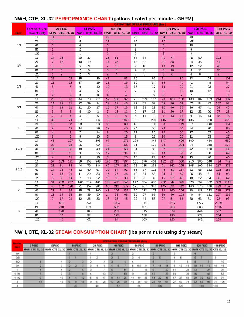
NHW CTE XL-32 NWH CTE XL-32 NWH CTE XL-32 NWH CTE XL-32 NWH CTE XL-32 NWH CTE XL-32 CTE XL-3210 11 17 22 29 34 4020 5 8 11 14 17 2040 3 4 5 7 8 1080 1 2 3 3 4 5120 1 1 2 2 3 310 14 24 20 37 28 51 35 64 41 77 48 90 10320 7 12 10 19 14 25 18 32 21 38 24 45 5140 3 6 5 9 7 13 9 16 10 19 12 22 2680 1 3 2 5 3 6 4 8 5 10 6 11 13120 1 2 2 3 2 4 3 5 3 6 4 8 910 22 25 35 39 47 53 60 67 71 80 83 94 10820 11 12 17 19 23 26 30 34 35 40 41 48 5440 5 6 9 10 12 13 15 17 16 20 21 23 2780 3 3 4 5 6 7 7 8 8 10 10 12 13120 2 2 3 3 4 4 5 6 6 7 7 8 910 28 51 43 44 78 67 59 106 92 75 133 117 90 160 138 103 187 163 214 18720 14 25 21 22 39 34 29 53 46 37 67 59 45 80 69 52 94 82 107 9340 7 13 11 11 20 17 15 27 23 19 33 29 22 40 35 26 47 41 54 4680 3 6 5 5 10 8 7 13 11 9 17 15 11 20 17 13 23 20 27 23120 2 4 4 4 7 6 5 9 8 6 11 10 7 13 11 9 16 14 18 1510 36 74 57 86 76 160 96 201 115 238 135 280 32220 18 37 28 58 38 80 48 100 58 119 67 140 16140 9 19 14 29 19 40 24 50 29 60 34 70 8080 4 9 7 14 9 20 12 25 15 30 17 35 40120 3 6 5 10 6 13 8 17 10 20 11 23 2710 46 127 71 198 97 271 123 344 147 406 169 480 55220 23 64 36 99 49 135 61 172 74 204 84 240 27640 11 32 18 49 24 68 31 86 37 101 42 120 13880 6 16 9 25 12 34 15 43 18 51 21 60 69120 4 11 6 16 8 23 10 29 12 34 15 40 4610 57 103 171 89 158 268 120 215 364 151 270 463 182 324 550 210 380 648 434 74220 28 51 85 44 79 134 60 107 182 75 135 232 91 162 275 105 190 324 217 37140 14 26 43 22 40 67 30 54 91 38 67 116 45 81 137 52 95 162 108 18680 7 13 21 11 20 33 15 27 46 19 34 58 23 41 69 26 48 81 54 93120 5 9 14 7 13 22 10 18 30 13 23 39 15 27 46 18 32 54 36 6210 91 203 257 142 214 401 192 425 545 242 534 696 292 642 825 320 752 972 859 111520 45 102 128 71 157 201 96 212 272 121 267 348 145 321 412 160 376 486 429 55740 23 51 64 35 78 100 48 106 136 60 133 174 73 160 206 80 188 243 215 27880 12 25 32 18 39 50 24 53 68 30 67 87 36 80 103 40 94 121 107 139120 9 17 21 12 26 33 18 35 45 22 44 58 27 54 68 30 63 81 72 9310 481 741 1004 1261 1517 1777 202920 240 371 502 631 758 888 101540 120 185 251 315 379 444 50780 60 93 125 158 190 222 254120 40 62 84 105 126 148 169
120 PSIGSize
TemperatureRise °F (DT)
20 PSIG 40 PSIG
1/2
60 PSIG 80 PSIG 100 PSIG
2
3
OPERATING STEAM PRESSURE (hm)
3/4
1
1 1/4
1 1/2
140 PSIG
1/4
3/8
NWH, CTE, XL-32 STEAM CONSUMPTION CHART (lbs per minute using dry steam)
NWH, CTE, XL-32 PERFORMANCE CHART (gallons heated per minute - GHPM)
14
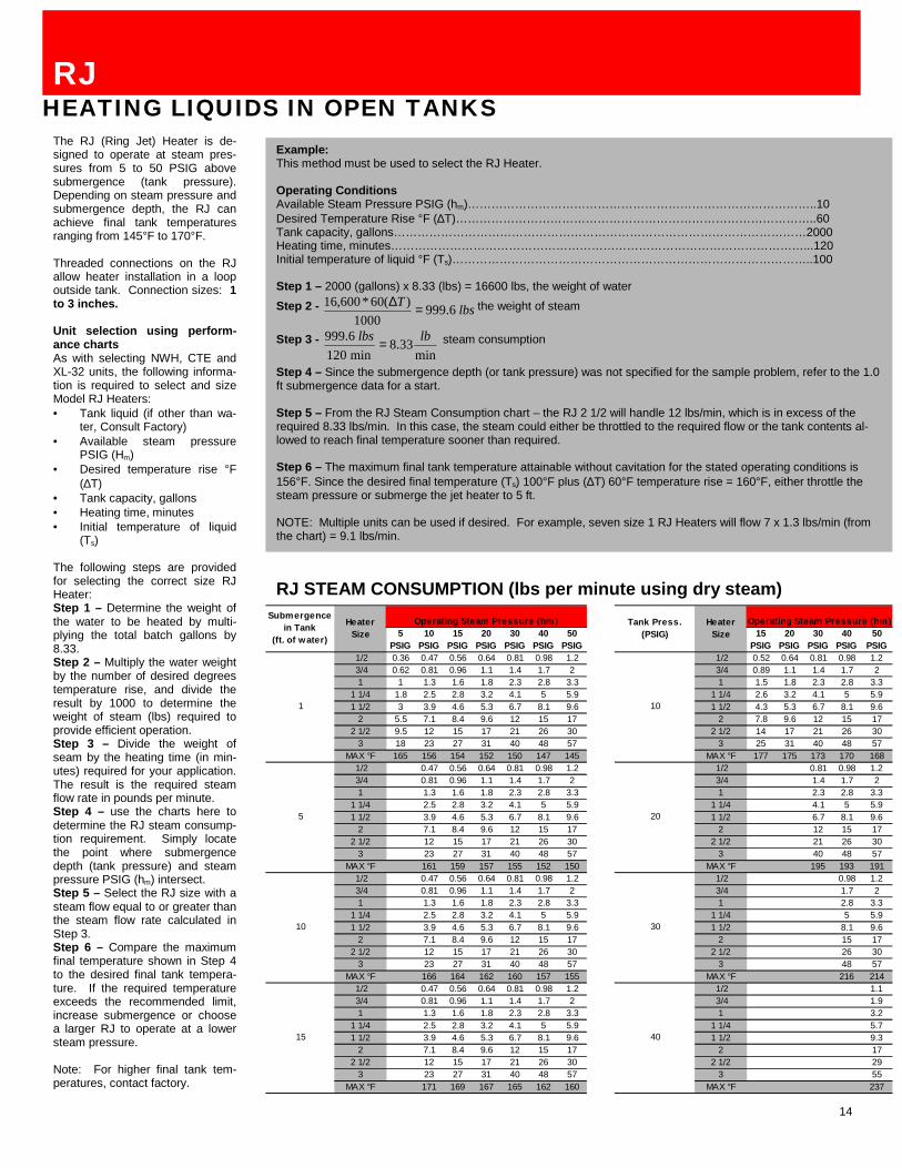
The RJ (Ring Jet) Heater is de-signed to operate at steam pres-sures from 5 to 50 PSIG abovesubmergence (tank pressure).Depending on steam pressure andsubmergence depth, the RJ canachieve final tank temperaturesranging from 145°F to 170°F.
Threaded connections on the RJallow heater installation in a loopoutside tank. Connection sizes: 1to 3 inches.
Unit selection using perform-ance chartsAs with selecting NWH, CTE andXL-32 units, the following informa-tion is required to select and sizeModel RJ Heaters:• Tank liquid (if other than wa-
ter, Consult Factory)• Available steam pressure
PSIG (Hm)• Desired temperature rise °F
(∆T)• Tank capacity, gallons• Heating time, minutes• Initial temperature of liquid
(Ts)
The following steps are providedfor selecting the correct size RJHeater:Step 1 – Determine the weight ofthe water to be heated by multi-plying the total batch gallons by8.33.Step 2 – Multiply the water weightby the number of desired degreestemperature rise, and divide theresult by 1000 to determine theweight of steam (lbs) required toprovide efficient operation.Step 3 – Divide the weight ofseam by the heating time (in min-utes) required for your application.The result is the required steamflow rate in pounds per minute.Step 4 – use the charts here todetermine the RJ steam consump-tion requirement. Simply locatethe point where submergencedepth (tank pressure) and steampressure PSIG (hm) intersect.Step 5 – Select the RJ size with asteam flow equal to or greater thanthe steam flow rate calculated inStep 3.Step 6 – Compare the maximumfinal temperature shown in Step 4to the desired final tank tempera-ture. If the required temperatureexceeds the recommended limit,increase submergence or choosea larger RJ to operate at a lowersteam pressure.
Note: For higher final tank tem-peratures, contact factory.
RJHEATING LIQUIDS IN OPEN TANKS
Example:This method must be used to select the RJ Heater.
Operating ConditionsAvailable Steam Pressure PSIG (hm)……………………………………………………………………………..10Desired Temperature Rise °F (∆T)………………………………………………………………………………..60Tank capacity, gallons……………………………………………………………………………………………2000Heating time, minutes……………………………………………………………………………………………...120Initial temperature of liquid °F (Ts)………………………………………………………………………………..100
Step 1 – 2000 (gallons) x 8.33 (lbs) = 16600 lbs, the weight of waterStep 2 - lbsT 6.999
1000)(60*600,16 =∆ the weight of steam
Step 3 - min
33.8min1206.999 lblbs = steam consumption
Step 4 – Since the submergence depth (or tank pressure) was not specified for the sample problem, refer to the 1.0ft submergence data for a start.
Step 5 – From the RJ Steam Consumption chart – the RJ 2 1/2 will handle 12 lbs/min, which is in excess of therequired 8.33 lbs/min. In this case, the steam could either be throttled to the required flow or the tank contents al-lowed to reach final temperature sooner than required.
Step 6 – The maximum final tank temperature attainable without cavitation for the stated operating conditions is156°F. Since the desired final temperature (Ts) 100°F plus (∆T) 60°F temperature rise = 160°F, either throttle thesteam pressure or submerge the jet heater to 5 ft.
NOTE: Multiple units can be used if desired. For example, seven size 1 RJ Heaters will flow 7 x 1.3 lbs/min (fromthe chart) = 9.1 lbs/min.
RJ STEAM CONSUMPTION (lbs per minute using dry steam)
1/2 0.36 0.47 0.56 0.64 0.81 0.98 1.2 1/2 0.52 0.64 0.81 0.98 1.23/4 0.62 0.81 0.96 1.1 1.4 1.7 2 3/4 0.89 1.1 1.4 1.7 21 1 1.3 1.6 1.8 2.3 2.8 3.3 1 1.5 1.8 2.3 2.8 3.3
1 1/4 1.8 2.5 2.8 3.2 4.1 5 5.9 1 1/4 2.6 3.2 4.1 5 5.91 1/2 3 3.9 4.6 5.3 6.7 8.1 9.6 1 1/2 4.3 5.3 6.7 8.1 9.6
2 5.5 7.1 8.4 9.6 12 15 17 2 7.8 9.6 12 15 172 1/2 9.5 12 15 17 21 26 30 2 1/2 14 17 21 26 30
3 18 23 27 31 40 48 57 3 25 31 40 48 57MAX °F 165 156 154 152 150 147 145 MAX °F 177 175 173 170 168
1/2 0.47 0.56 0.64 0.81 0.98 1.2 1/2 0.81 0.98 1.23/4 0.81 0.96 1.1 1.4 1.7 2 3/4 1.4 1.7 21 1.3 1.6 1.8 2.3 2.8 3.3 1 2.3 2.8 3.3
1 1/4 2.5 2.8 3.2 4.1 5 5.9 1 1/4 4.1 5 5.91 1/2 3.9 4.6 5.3 6.7 8.1 9.6 1 1/2 6.7 8.1 9.6
2 7.1 8.4 9.6 12 15 17 2 12 15 172 1/2 12 15 17 21 26 30 2 1/2 21 26 30
3 23 27 31 40 48 57 3 40 48 57MAX °F 161 159 157 155 152 150 MAX °F 195 193 191
1/2 0.47 0.56 0.64 0.81 0.98 1.2 1/2 0.98 1.23/4 0.81 0.96 1.1 1.4 1.7 2 3/4 1.7 21 1.3 1.6 1.8 2.3 2.8 3.3 1 2.8 3.3
1 1/4 2.5 2.8 3.2 4.1 5 5.9 1 1/4 5 5.91 1/2 3.9 4.6 5.3 6.7 8.1 9.6 1 1/2 8.1 9.6
2 7.1 8.4 9.6 12 15 17 2 15 172 1/2 12 15 17 21 26 30 2 1/2 26 30
3 23 27 31 40 48 57 3 48 57MAX °F 166 164 162 160 157 155 MAX °F 216 214
1/2 0.47 0.56 0.64 0.81 0.98 1.2 1/2 1.13/4 0.81 0.96 1.1 1.4 1.7 2 3/4 1.91 1.3 1.6 1.8 2.3 2.8 3.3 1 3.2
1 1/4 2.5 2.8 3.2 4.1 5 5.9 1 1/4 5.71 1/2 3.9 4.6 5.3 6.7 8.1 9.6 1 1/2 9.3
2 7.1 8.4 9.6 12 15 17 2 172 1/2 12 15 17 21 26 30 2 1/2 29
3 23 27 31 40 48 57 3 55MAX °F 171 169 167 165 162 160 MAX °F 237
5
10
15
Tank Press. (PSIG)
30
40
Heater Size
Submergencein Tank
(ft. of water)
Operating Steam Pressure (hm)
1 10
20
Operating Steam Pressure (hm)20
PSIG30
PSIG40
PSIG50
PSIG5
PSIG10
PSIG15
PSIG20
PSIG30
PSIG40
PSIG50
PSIG15
PSIG
Heater Size

15
NWH, CTE, XL-32, RJ models
Heater Size A C D F M1/4 1 3/4 1 1/2 1/4 3/8 103/8 2 1/2 2 3/8 1/2 101/2 2 5/8 2 1/8 1/2 1 103/4 2 7/8 2 1/4 3/4 1 101 2 7/8 2 3/8 1 1 1/4 12
1 1/4 3 5/8 2 3/4 1 1/4 1 1/4 121 1/2 4 1/8 3 3/8 1 1/2 2 12
2 4 7/8 3 3/8 2 2 1/2 12
Heater Size A C D3/8* 4 1/2 1 3/4 3/83/4* 6 2 1/4 3/41 1/2 7 1/4 3 1 1/2
2 11 1/4 4 1/4 23 19 3/8 6 1/2 3
HeaterSize A B* C D* E* F G H J K L* M1/2 4 1/4 2 1 1/2 1/2 1/4 1 7/8 1 1/2 7/8 2 3/4 2 3/4 1/4 App. 123/4 4 1/2 2 1/2 1 5/8 3/4 1/4 2 1/8 1 3/4 7/8 2 7/8 3 1/4 1/4 App. 121 5 3 1 3/4 1 1/4 2 1/2 2 1 3 1/4 4 1/4 App. 12
1 1/4 5 1/2 4 2 1 1/4 1/4 2 7/8 2 1/2 1 1/8 3 1/2 5 3/8 App. 121 1/2 6 5 2 3/8 1 1/2 1/4 3 5/8 3 1/4 1 1/4 3 3/4 6 3/8 App. 18
2 6 3/4 7 2 3/4 2 3/8 4 3/4 4 1/4 1 5/8 4 1/8 8 1/4 3/8 App. 18
Heater Size A B C D E F1 7 1/8 2 1/4 1 3/4 3/4 1 1
1 1/4 9 2 1/2 2 1/4 1 1 1/4 1 1/41 1/2 11 2 3/4 2 1/2 1 1/4 1 1/2 1 1/2
2 14 3/8 3 1/8 3 1 1/2 2 22 1/2 18 1/8 3 1/2 4 1/8 2 2 1/2 2 1/2
3 23 7/8 4 5 2 3 3
NWH DIMENSIONS (in inches)
CTE DIMENSIONS (in inches)
XL-32 DIMENSIONS (in inches)
RJ DIMENSIONS (in inches)
*Male NPT
*NPT nominal pipe size

16
Penberthy Steam Jet Heaters areeasy to install and operate. Hereare some general guidelines toinstalling, operating and maintain-ing steam jet heaters. Completeinstructions are supplied with eachheater.
InstallationPenberthy Steam Jet Heaters willoperate in any position. However,the steam jet inlet should pointupward to help rid the steam lineof condensation at start-up. Theuse of piping, elbows and valvesshould be minimal to limit frictionlosses. Support piping to avoidputting stress on the steam jetheater.
Inlet and steam piping
Piping must be large enough tosupply the heater under maximumflow conditions. Pressures shouldbe as specified in the performancedata for the application whenmeasured at the heater.
Discharge piping
Piping size should be equal to thatof the heater. With long dischargelines, pipe size should be in-creased to minimize the discharge
head. If a valve is used in thedischarge line to reduce pressureduring start-up, the valve outletcan be connected to a drain. Itcan also be connected to a tank inthe process or returned to thesuction side of the pump supplyingliquid pressure.
Start-up steam jet heaters
Steam should be adjusted to thefull required pressure. When thedesired temperature has beenreached, steam pressure shouldbe shut off completely (rather thanthrottled) to avoid hammer. If theheater is thermostatically con-trolled, the steam flow should notbe throttled past the recommendedoperating level. A snap-acting on-off steam control valve should beused.
Maintenance
When properly selected, Penber-thy Steam Jet Heaters will operatefor extended periods withoutmaintenance. Faulty operation orreduced performance may becaused by scale or foreign matterin the lines. Installing strainers inthe inlet lines can thus help im-prove performance.
installation and operationCONSIDERATIONS WHEN INSTALLINGOR OPERATING STEAM JET HEATERS
30
29
28
27
26
25
24
23
22
21
20
19
18
17
16
15
14
13
12
11
10
9
8
7
6
5
4
3
2
1
0
1
2
3
4
5
6 36
35
34
33
32
31
30
29
28
27
0
1
3
2
4
16
10
7
6
5
9
8
13
11
12
14
15
17
18
20
19
21
24
23
22
25
26
0
1
2
3
4
5
6
7
8
9
10
11
12
13
14
15
16
17
18
14.7 0
1
2
3
01234567
123456789
10111213141516171819202122232425262728293031323334
PRESSURE/VACUUM COMPARATIVE SCALES
IN. HG. ABS. PSIA PSIG FT. WATER
ABSOLUTE ZERO PRESSURE
ATMOSPHERIC PRESSURE
FT. WATER DISCHARGE HEAD
FT. WATER SUCTION LIFT
IN. HG. GAGE
IN. HG. VACUUM
PRESSURE/VACUUM COMPARATIVE SCALES
Unit conversions
1 kPa = 0.145 PSIG 1kg/hr = 2.205 lb/hr = 0.335 ft water 1kg/cm3 = 28.96 in Hg (20°C) (20°C) 1 W = 0.0568 BTU/min = 0.295 in Hg (20°C) 1 l = 0.2642 gal1 cm = 0.394 in 1°C = (°F-32)÷1.81m3/min = 264.2 GPM
Typical in-line jet type heater installation
PENBERTHY320 Locust Street, Prophetstown, IL 61277-1177 USATEL: (815) 537-2311 FAX: (815) 537-5764
1987 Penberthy. All rights reserved


