JESCO UV 405-412-440-450-480-550-80 2 LCD – LCD PLUS · 2016-07-05 · UV...
24
A measured step forward Operations & Maintenance Manual JESCO UV 405-412-440-450-480-550-80 2 LCD – LCD PLUS TM
Transcript of JESCO UV 405-412-440-450-480-550-80 2 LCD – LCD PLUS · 2016-07-05 · UV...

A measured step forwardOperations & Maintenance Manual
JESCO UV 405-412-440-450-480-550-80
2 LCD – LCD PLUS
TM

P h o n e : ( 5 8 5 ) 4 2 6 - 0 9 9 0 w w w . l u t z j e s c o a m e r i c a . c o m Fax: (585) 426-4025
Contents
1. Introduction ..................................................................................................................3
2. General Principles and Safety Instructions .................................................................4
3. Instructions for Installation and Setting at Work ........................................................53.1 Suggested Install Scheme ......................................................................................................... 6
4. UV Chamber Installation ...............................................................................................74.1 UV Chamber Assembling ........................................................................................................... 74.2 UV Chamber Detailed Drawing ................................................................................................... 9
5. Electrical Panel Installation and Operation ...............................................................105.1 Control Panel Description ........................................................................................................ 105.2 Electrical Panel Installation and Operation ................................................................................. 115.3 Switch ON / Switch OFF the lamps ........................................................................................... 115.2 Control Panel Detailed Drawing ................................................................................................ 12
6. LCD Electrical Board Description ...............................................................................136.1 Single-lamp LCD Electrical Board Description (UV 405, 412, 440, 480) ...................................... 136.2 Two-Lamp LCD Electrical Board Description (UV 450, 550, 80/2) ............................................... 146.3 LCD Display Board Description ................................................................................................. 15
7. Display Information (Troubleshooting) ......................................................................16
8. Maintenance ...............................................................................................................22
9. Warranty Conditions ...................................................................................................23

February 2016 3P h o n e : ( 5 8 5 ) 4 2 6 - 0 9 9 0 w w w . l u t z j e s c o a m e r i c a . c o m Fax : (585) 426-4025
Ope
ratio
n &
Mai
nten
ance
Inst
ruct
ions
JE
SCO
UV1. IntroductionThis manual is for the following models of LCD SERIES:
UV 405-412-440-450-480-550-80/2 LCD-LCD PLUS
Warning: This equipment requires regular maintenance to ensure the requirements of the drinking water treated and the maintenance of the improvements as stated by the manufacturer.
These operating instructions contain important information for the operation and maintenance of the equip-ment.
Please ensure that these operating instructions are carefully read by all relevant persons before putting into operation, to ensure the safe use of the UV system. The operating instructions are an integral part of the equipment supply.
Before putting into operation, all the conditions necessary for safe operation of the equipment must be ful-filled.
The installation, commissioning and maintenance of the equipment should only be carried out by qualified personnel.
The equipment should only be operated by authorized personnel who have been trained accordingly.
No modifications should be made to the equipment without consulting Jesco, as this could affect the safe op-eration of the unit. Jesco shall not be held responsible for damage resulting from unauthorized modifications.
INSTRUCTION:
The operating instructions are to be kept where they will be accessible for operating and maintenance personnel.

February 20164 P h o n e : ( 5 8 5 ) 4 2 6 - 0 9 9 0 w w w . l u t z j e s c o a m e r i c a . c o m Fax : (585) 426-4025
Ope
ratio
n &
Mai
nten
ance
Inst
ruct
ions
JE
SCO
UV
4
2. General Principles and Safety InstructionsInformation about UV irradiation:
The UV disinfection system of the LCD series has been designed specifically for destroying harmful bacteria and viruses present in your water.
The UV light emitted by special mercury vapor lamps (UV-C rays l= 254nm) is highly germicidal because it in-teracts with DNA and RNA at a molecular level.
The deep bio-structural disorder caused by such irradiation interferes with the ability of micro-organisms to de-velop and reproduce, rendering them harmless.
Generally, it is better to mount a pre-filter onto the UV sterilizer in order to remove contaminates and particles that could interfere with the ultraviolet process.
This system is necessary if a high degree of sterilization is required. In fact, the nonfiltration and removal of sus-pended particles in water has, as a consequence, a decrease in the sterilizer’s efficiency.
If the water to be treated contains sulphydric acid or more than 0.3 p.p.m. of iron or filtrable solids, once passed through the sterilizer, it leaves a residual sediment on the quartz sleeve which must be cleaned peri-odically (the frequency depends on the quantity and quality of water treated).
General directions:
According to the European rules EN 60204-1 (safety of the set-up off the electrical equipment-general rules) the low tension electrical instruments (rule 2006/95/CE) must be connected to a current-tap provided with grounding.
Electrical Safety Instructions:
The lightning flash and arrowhead symbol is to alert the user to the presence of un-insulated “DANGEROUS VOLTAGE” within the enclosure. The equipment may only be opened if main sup-ply is isolated. The main supply must not be restored as long as the equipment is open. This applies to both the electrical panel and the UV reactor vessel.
ATTENTION: Working on live equipment is prohibited.
UV Light Danger:
The light of ultra-violet lamps can cause serious burns to unprotected skin and eyes, therefore it is recommended not to connect it to the current tap without before having ensured that the UV lamp is in its housing and inserted in the PVC cover.
Pressure Danger:
The UV chamber could be under water pressure. Max working pressure is 145 psig (10 bar). UV chamber must be installed in accordance with our installation and commissioning instructions and used in accordance with operating and maintenance instructions.
ATTENTION: Ensure that system is depressurized before attempting any service or repair.
Indications for the disposal:
Please note that, according to what is outlined by D.L.25 July 2005, № 151 “Accomplishment of directives 2002/CE, 2002/96/CE and 2003/108/CE, concerning the reduction of the use of dangerous substances in electric and electronic equipment, and the disposal of waste” both mercury vapor lamps and electrical panels, when no longer in use, must be treated as special waste, and as such disposed of.
To do that, please contact specialized centers for the recycling of dangerous materials, or contact our techni-cal department directly.

February 2016 5P h o n e : ( 5 8 5 ) 4 2 6 - 0 9 9 0 w w w . l u t z j e s c o a m e r i c a . c o m Fax : (585) 426-4025
Ope
ratio
n &
Mai
nten
ance
Inst
ruct
ions
JE
SCO
UV3. Instructions for Installation and Setting at WorkGeneral premise: The installation of the DOMESTIC SERIES disinfection units must be carried out by special-ized staff, exactly following the instructions hereby provided. Moreover, it is necessary to provide some general information about electrical and water connections.
Caution: check that the UV panel is not connected to the power supply and that the tap of the water to be treated is turned off.
� Connect the delivery of the water to be treated to the special water connection � Turn on water and check for possible leaks in any part of the unit � Connect the plug to the current tap � Check that the disinfected water comes out and that the LEDS on the panel on the control board, signal
correct functioningAllow the disinfected water flow down to outlet for at least 10 minutes before utilization, in order to allow pos-sible impurities present in the unit to drain out.
NOTE: it is recommended to mount a water filter directly onto the UV sterilizer in order to remove suspended particles, potentially present in the water to be treated, which could limit the efficiency of sterilization.
CHECKS
The DOMESTIC SERIES is ready for producing disinfected water, once the connection to the water system and to the electrical grid is carried out. The unit works automatically, the electronic boards which control the sig-nals reaching the control panel, allow the visualizing (or the sounding) of the correct functioning or of anoma-lies which may occur during the operation of the unit.

February 20166 P h o n e : ( 5 8 5 ) 4 2 6 - 0 9 9 0 w w w . l u t z j e s c o a m e r i c a . c o m Fax : (585) 426-4025
Ope
ratio
n &
Mai
nten
ance
Inst
ruct
ions
JE
SCO
UV 3.1 Suggested Install Scheme

February 2016 7P h o n e : ( 5 8 5 ) 4 2 6 - 0 9 9 0 w w w . l u t z j e s c o a m e r i c a . c o m Fax : (585) 426-4025
Ope
ratio
n &
Mai
nten
ance
Inst
ruct
ions
JE
SCO
UV4. UV Chamber Installation
4.1 UV Chamber AssemblingMount the valve kit supplied with the system.
Unscrew the sleeve bolts:
Insert the quartz sleeves carefully centering the spring at the bottom plate of the UV chamber:
Insert the o-ring Ø 23x4 into the quartz sleeve:
February 20168 P h o n e : ( 5 8 5 ) 4 2 6 - 0 9 9 0 w w w . l u t z j e s c o a m e r i c a . c o m Fax : (585) 426-4025
Ope
ratio
n &
Mai
nten
ance
Inst
ruct
ions
JE
SCO
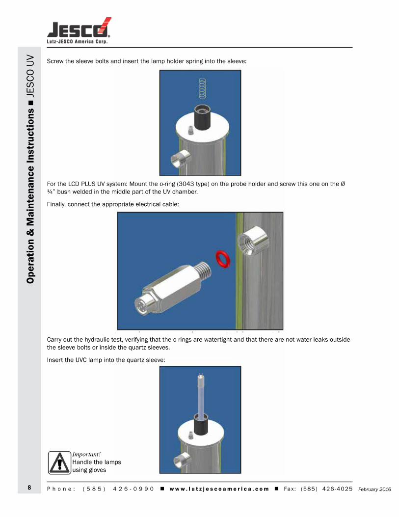
UV Screw the sleeve bolts and insert the lamp holder spring into the sleeve:
For the LCD PLUS UV system: Mount the o-ring (3043 type) on the probe holder and screw this one on the Ø ¼” bush welded in the middle part of the UV chamber.
Finally, connect the appropriate electrical cable:
Carry out the hydraulic test, verifying that the o-rings are watertight and that there are not water leaks outside the sleeve bolts or inside the quartz sleeves.
Insert the UVC lamp into the quartz sleeve:
Important!Handle the lamps using gloves

February 2016 9P h o n e : ( 5 8 5 ) 4 2 6 - 0 9 9 0 w w w . l u t z j e s c o a m e r i c a . c o m Fax : (585) 426-4025
Ope
ratio
n &
Mai
nten
ance
Inst
ruct
ions
JE
SCO
UV4.2 UV Chamber Detailed Drawing

February 201610 P h o n e : ( 5 8 5 ) 4 2 6 - 0 9 9 0 w w w . l u t z j e s c o a m e r i c a . c o m Fax : (585) 426-4025
Ope
ratio
n &
Mai
nten
ance
Inst
ruct
ions
JE
SCO
UV 5. Electrical Panel Installation and Operation
5.1 Control Panel Description
Control Panel LCD (PLUS)Material and colour Black PolypropyleneDimensions 8 x 8 x 3 in.Protection class IP 55 (IP 65 on request)Ambient temperature range 41 – 113 °FPower supply 230 V - 50/60 Hz (115V – 50/60 Hz on request)Lamp cable 3 ft.Power supply cable 3 ft.Monitor display LCDHour meter Yes for total system lifeResettable hour meter Yes for lamp life controlLamp function control YesAlarm led YesFree contact (NO - NC) Yes – general alarm230 V output (NO - NC) Yes – general alarmRemote ON/OFF contact Yes (settable)ON/OFF Timer Yes (settable)Reactor temperature measurement and alarm Yes (°F) – settable value (shut off for high temperature) on PLUS
MODELSUV Irradiance measurement and alarm Yes (% or W/m2 optional) – settable value on PLUS MODELS4/20 mA output Optional – for Irradiance and water temperature on PLUS MODELSAudio alarm Optional

February 2016 11P h o n e : ( 5 8 5 ) 4 2 6 - 0 9 9 0 w w w . l u t z j e s c o a m e r i c a . c o m Fax : (585) 426-4025
Ope
ratio
n &
Mai
nten
ance
Inst
ruct
ions
JE
SCO
UV5.2 Electrical Panel Installation and OperationThe electrical panel of the LCD series is equipped with 2 fixing brackets for wall mounting. Rotating the panel cover, the user can have the cable out on the desired sides of the panel.
Connect the lamp socket to the lamp and close the contact cover cap, then connect the power supply plug to the main supply.
Once connected to the power supply the UV lamp will light up.
Do the following at the first start up and with every lamp replacement:
1) Activate the lamp life count down hour meter (see display description)
2) For the LCD PLUS system with UV sensor: operate the sensor calibration. This operation must be conducted after at least 5 minutes of lamp start, with quartz sleeve clean, with sensor measuring window clean and with steady water flow.
5.3 Switch ON / Switch OFF the lampsBecause of the small power of the electrical panel this is not equipped with power selector. Therefore, the panel is always powered but lamps can be switched ON/OFF in the following ways:1. Holding down the OK (◄┘) button for 5 seconds (see display description)2. Closing the remote ON/OFF contact (see electrical scheme)3. Setting the timer (see display description)

February 201612 P h o n e : ( 5 8 5 ) 4 2 6 - 0 9 9 0 w w w . l u t z j e s c o a m e r i c a . c o m Fax : (585) 426-4025
Ope
ratio
n &
Mai
nten
ance
Inst
ruct
ions
JE
SCO
UV 5.2 Control Panel Detailed Drawing

February 2016 13P h o n e : ( 5 8 5 ) 4 2 6 - 0 9 9 0 w w w . l u t z j e s c o a m e r i c a . c o m Fax : (585) 426-4025
Ope
ratio
n &
Mai
nten
ance
Inst
ruct
ions
JE
SCO
UV6. LCD Electrical Board Description
6.1 Single-lamp LCD Electrical Board Description (UV 405, 412, 440, 480)

February 201614 P h o n e : ( 5 8 5 ) 4 2 6 - 0 9 9 0 w w w . l u t z j e s c o a m e r i c a . c o m Fax : (585) 426-4025
Ope
ratio
n &
Mai
nten
ance
Inst
ruct
ions
JE
SCO
UV 6.2 Two-Lamp LCD Electrical Board Description (UV 450, 550, 80/2)

February 2016 15P h o n e : ( 5 8 5 ) 4 2 6 - 0 9 9 0 w w w . l u t z j e s c o a m e r i c a . c o m Fax : (585) 426-4025
Ope
ratio
n &
Mai
nten
ance
Inst
ruct
ions
JE
SCO
UV6.3 LCD Display Board DescriptionThe standard and optional terminal connections to the display board are as follows:
� It is possible to connect the sensor cable (usually this is connected on the main board). � It is possible to connect the REMOTE ON/OFF contact, this is powered with 5Vdc that if closed to the RMT
contact shuts of the lamps. The user can set the working of the remote ON/OFF contact by the display between N/O and N/C. The factory setting is N/O because it let the system working with nothing connected to the remote ON/OFF terminal.
� In case of LCD PLUS systems with optional 4/20 mA output then it’s possible to connect to the 4/20 mA terminal. This signal is available for the water temperature and the UV irradiance.
The temperature signal has the following correspondence:
4mA = 32 °F (0°C) 20 mA = 212 °F (100 °C)
The irradiance signal has the following correspondence:
4mA = 0% 20 mA = Settable value on the display (factory setting 20 mA= 100%)
ImportantThe 4/20 mA output signal can work with a max load of 150 ohm

February 201616 P h o n e : ( 5 8 5 ) 4 2 6 - 0 9 9 0 w w w . l u t z j e s c o a m e r i c a . c o m Fax : (585) 426-4025
Ope
ratio
n &
Mai
nten
ance
Inst
ruct
ions
JE
SCO
UV 7. Display Information (Troubleshooting)

February 2016 17P h o n e : ( 5 8 5 ) 4 2 6 - 0 9 9 0 w w w . l u t z j e s c o a m e r i c a . c o m Fax : (585) 426-4025
Ope
ratio
n &
Mai
nten
ance
Inst
ruct
ions
JE
SCO
UV

February 201618 P h o n e : ( 5 8 5 ) 4 2 6 - 0 9 9 0 w w w . l u t z j e s c o a m e r i c a . c o m Fax : (585) 426-4025
Ope
ratio
n &
Mai
nten
ance
Inst
ruct
ions
JE
SCO
UV

February 2016 19P h o n e : ( 5 8 5 ) 4 2 6 - 0 9 9 0 w w w . l u t z j e s c o a m e r i c a . c o m Fax : (585) 426-4025
Ope
ratio
n &
Mai
nten
ance
Inst
ruct
ions
JE
SCO
UV

February 201620 P h o n e : ( 5 8 5 ) 4 2 6 - 0 9 9 0 w w w . l u t z j e s c o a m e r i c a . c o m Fax : (585) 426-4025
Ope
ratio
n &
Mai
nten
ance
Inst
ruct
ions
JE
SCO
UV

February 2016 21P h o n e : ( 5 8 5 ) 4 2 6 - 0 9 9 0 w w w . l u t z j e s c o a m e r i c a . c o m Fax : (585) 426-4025
Ope
ratio
n &
Mai
nten
ance
Inst
ruct
ions
JE
SCO
UV

February 201622 P h o n e : ( 5 8 5 ) 4 2 6 - 0 9 9 0 w w w . l u t z j e s c o a m e r i c a . c o m Fax : (585) 426-4025
Ope
ratio
n &
Mai
nten
ance
Inst
ruct
ions
JE
SCO
UV 8. MaintenanceThe UV System of DOMESTIC SERIES has been designed and realized by Jesco with simple and functional prin-ciples which make the checking procedures and the periodical servicing particularly easy.
The main points which characterize the standard servicing are the following: check quarterly the quartz sleeves, which contain the UV lamps, in order to ensure maximum disinfection for cleaning.
Maintenance work may only be carried out by personnel who have been trained and authorized for this work by the owner and/or user. The owner and/or user must ensure that the maintenance personnel are familiar with the safety measures and regulations, and that they also comply with them; in addition to having read and understood the operating instructions.
Only original replacement parts from the supplier must be used.
The following are the recommended service intervals for replacement parts:
UV lamp change - once per 9000 hours UV quartz sleeve clean - frequency depends on the quality of the water O-ring for quartz sleeve-once per year
Procedure for UV lamp replacement (9000 h max.)
1) Disconnect the electrical box from the electrical power supply2) Lift the cover slightly by turning, carefully loosening the electrical 4-pins connection and extract the lamp
from the quartz sleeve 3) Remove the lamp from the packing, handling it carefully by its ends or by using gloves4) Insert the new lamp into the quartz sleeve of the sterilizer5) Connect the lamp to the electrical connection and replace the cover6) Connect the equipmentImportant!
For lamp replacement, it is not necessary to stop the water flow and drain the UV chamber.
Procedure for quartz sleeve cleaning
1) Disconnect the electrical box from the electrical grid and turn off water2) Remove the lamp, following the lamp replacement instructions.3) Depressurize and drain the UV system4) Unscrew the sleeve-bolt and extract the quartz sleeve with care5) Clean the quartz sleeve by wiping it with a cloth soaked with an acid solution such as vinegar or lemon6) Reassemble the sleeve being sure to center the guide-spring fixed on the bottom, put the o-ring on the
quartz sleeve, then tighten the sleeve-bolt; place the o-ring in the seat of the sleeve-bolt, insert the sleeve inside it, till it leans, then screw on the S/S chamber
7) Turn on water checking for possible leaks8) Remount lamp, electrical connection and cover9) Turn on the UV system

February 2016 23P h o n e : ( 5 8 5 ) 4 2 6 - 0 9 9 0 w w w . l u t z j e s c o a m e r i c a . c o m Fax : (585) 426-4025
Ope
ratio
n &
Mai
nten
ance
Inst
ruct
ions
JE
SCO
UV9. Warranty ConditionsJESCO works in compliance with ISO 9001-2008 quality procedures and subjects all equipment to accurate checks and tests.
JESCO products are guaranteed only within the limits of technical specifications and request and/or of the certificates and/or of the specific checks as agreed, for 24 months from the delivery date or 30 days from the purchase date, provided that defects are reported immediately.
The stainless steel chamber is covered by a 5-year warranty only if used with compatible liquids and correctly installed.
In no case is the integral replacement of the product foreseen and any responsibility of JESCO is excluded for delays in the delivery of the goods to the customer, for claims of third parties against the customer, for losses of goods, costs (installation, servicing and maintenance, transport, and etc.) and damages of the customer due to the defect.
Moreover, the product repaired or tampered with by non-authorized third parties, and the product on which an intervention has been made for defect or for convenience tests, is excluded from the warranty.
Repairs are normally carried out in the JESCO facility or in authorized after-sales service centers approved by JESCO.
The warranty does not cover:1. Accidental breakages due to transport.2. Breakages due to the use of equipment not in compliance with what is indicated on the use and mainte-
nance manual or due to carelessness.3. Breakages to the connection to a power grid fed with a tension different than the foreseen one (±10% of
the nominal value as fixed by CEI rules)
DO NOT TAMPER WITH THE ADHESIVE IDENTIFICATION LABELS
The adhesive label with the QC (Quality Control) number must remain intact and legible; such number allows to enter the data bank of tests and to find the values obtained in the electrical test of the equipment.
The adhesive label with the S/N (Serial Number) number must remain intact and legible; such number allows to enter the data bank of tests and to find the values obtained in the hydraulic test of the equipment.

Lutz-JESCO America Corp. 55 Bermar Park Phone: +1-585-426-0990 E-Mail: [email protected] Toll Free: Rochester, NY 14624 USA Fax: +1-585-426-4025 Internet: www.lutzjescoamerica.com 1-800-554-2762
Met
erin
g Pu
mps
Tran
sfer
Pum
ps
M
easu
ring
and
Cont
rol T
echn
olog
y
Che
mica
l Fee
d Sy
stem
s
Acc
esso
ries
Febr
uary
201
6