Jenway 6300 Spectrophotometer Service Manual 6300 mk 2 ser... · 2009-03-24 · Jenway 6300 Ser Man...
67
Jenway 6300 Ser Man 1 Jenway 6300 Spectrophotometer Service Manual Main Index Section 1 Introduction Section 2 Quick Reference Section 3 System Description Section 4 Optical Description Section 5 Electronic Description Section 6 Software and Operation Section 7 Diagnostics Section 8 Maintenance Section 9 Circuit Diagrams Section 10 Assembly Diagrams Section 11 Spare Parts List
Transcript of Jenway 6300 Spectrophotometer Service Manual 6300 mk 2 ser... · 2009-03-24 · Jenway 6300 Ser Man...
Jenway 6300 Ser Man 1
Jenway 6300Spectrophotometer Service Manual
Main Index
Section 1 Introduction
Section 2 Quick Reference
Section 3 System Description
Section 4 Optical Description
Section 5 Electronic Description
Section 6 Software and Operation
Section 7 Diagnostics
Section 8 Maintenance
Section 9 Circuit Diagrams
Section 10 Assembly Diagrams
Section 11 Spare Parts List

Jenway 6300 Ser Man 2
Section 1
Introduction
1.0 Index to Sections
1.1 About This Manual
1.2 Using This Manual
1.3 Warnings & Safe Practice
1.4 Standards & Certification
1.5 Ordering Spares
1.6 Returning Items
1.7 Contacting Jenway Limited
Jenway 6300 Ser Man 3
Introduction.
1.0 Index to Sections
Section 1 – Introduction1.0 Index to Sections1.1 About This Manual1.2 Using This Manual1.3 Warnings & Safe Practice1.4 Standards & Certification1.5 Ordering Spares1.6 Returning Items1.7 Contacting Jenway Limited
Section 2 - Quick Reference2.0 About ‘Quick Reference’2.1 Specification2.2 Main Sub-Assemblies2.3 Power Supply Voltages2.4 Signal Levels2.5 Error Codes2.6 Special Key Functions2.7 Test Solutions
Section 3 - System Description3.1 Background3.2 Sub-Assemblies3.3 Accessories3.4 Outputs
Section 4 - Optical Description4.1 Light source4.2 Grating4.3 Shutter and Filter4.4 Signal Detector
Jenway 6300 Ser Man 4
Section 5 - Electronic Description5.1 Power Supplies5.2 Detector Circuit5.3 Microprocessor and Display
Section 6 - Software and Operation6.0 Warning6.1 Start Up Routine6.2 Photometrics6.3 Concentration
Section 7 – Diagnostics7.1 Diagnostics Mode7.2 Shutter and Filter Control7.3 Lamp Control7.4 Zero Order Calibration.
Section 8 – Maintenance8.1 Routine Maintenance8.2 Dismantling8.3 Optical Alignment8.4 Energy Levels8.5 Wavelength Calibration8.6 A to D Calibration8.7 D to A Calibration8.8 Performance Verification
Jenway 6300 Ser Man 5
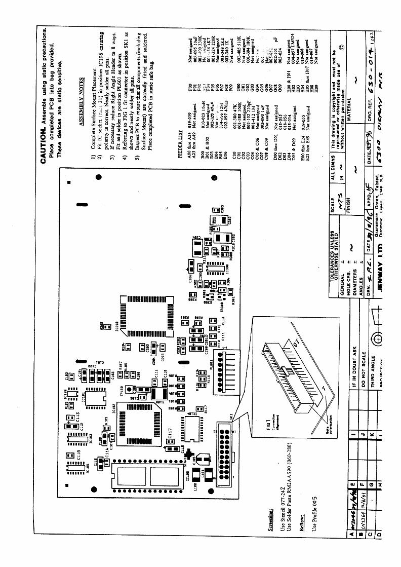
Section 9 - Circuit Diagrams9.1 Supply Schematic 630 5049.2 Power Supply Layout 630 5049.3 Detector PCB Schematic 630 5069.4 Detector PCB Layout 630 5069.5 Microprocessor PCB Schematic 630 0139.6 Microprocessor PCB Layout 630 013
Section 10 - Assembly Diagrams10.1 6300 Final Assembly 630 50310.2 6300 Lower Case Assembly 630 51010.3 6300 Top Case Assembly 630 01010.4 6300 Optics Assembly 630 50810.5 6300 Rear Panel Assembly 630 012
Section 11 – Spare Parts List11.01 Packed Instrument11.02 Top Case Assembly11.03 Microprocessor/display PCB11.04 Lower Case Assembly11.05 Lamp Housing Assembly11.06 Monochromator Assembly11.07 Detector PCB11.08 Power Supply PCB11.09 Rear Panel Assembly
Jenway 6300 Ser Man 6
1.1 About This Manual
This manual covers the service, maintenance, calibration and repairof the Jenway Ltd model 6300 Spectrophotometer. (From serialnumber 5000 upwards, for lower numbers please refer to 6300Mk1 Manual)This manual must be used in conjunction with the InstructionManual for this model, as many of the routine maintenanceprocedures detailed in the Instruction Manual are not repeated inthis Service Manual.
1.2 Using This Manual
This manual is only for the use of Engineers and Technicians whohave successfully completed a Jenway Ltd approved ServiceTraining course on the Model 6300 Spectrophotometer.
Updates to this manual will be circulated through the Jenway LtdTSI (Technical Service Information) systems and to otherregistered users of this manual. Please complete the form at the rearof this manual to register your copy for future updates.
In practice Section 2 - Quick Reference and Section 8 –Maintenance, with the Diagrams in Section 9 and 10, will be mostfrequently used, however it is good practice to read the completemanual initially and review it again periodically.
To find the information required refer to the Main Index or Indexto Sections to identify the relevant Section/page number required.
1.3 Warnings & Safe Practice
Always disconnect the mains supply when any covers are removedas there are voltages present inside the unit that pose the risk ofelectric shock at levels that are hazardous to life!
Do not look directly at the light source or allow the light beam tofall directly on the eyes, switch off or dim the lamp (as described in
Jenway 6300 Ser Man 7
the procedures) whenever possible and wear eye protection at ALLtimes.
The lamp gets very hot when in use, always allow time for it tocool down before removal. Always wear cotton gloves whenremoving a faulty lamp and replacing with a new one.
Finger marks, dust and condensation can quickly destroy sensitiveand expensive optical components, always wear cotton gloveswhen the optical bench is uncovered and handle any componentsby their edges only. Never touch optical surfaces. Do not removeoptical covers unless the unit is in a clean, dust and condensationfree environment.
Many of the reagents, solutions and standards used for maintenanceand calibration are corrosive or hazardous, ensure all precautionssupplied with them are followed, where there is any doubt request aMSDS (Material Safety Data Sheet) from the supplier.
This instrument can be used for analysing a broad range ofsamples, do not handle them unless you are qualified to do so.Ensure that the instrument has been correctly decontaminatedbefore working on it, specifically in areas where the instrumentmay have been used for clinical, biological, corrosive orradioactive samples.
1.4 Standards & Certification
No adjustments should be made to this instrument unless the testand measurement equipment, signal source or filters to be usedhave a current calibration certificate that is traceable to national orinternational standards and that it is known that this test equipmentis currently performing to the certified standards. All solutions andreagents should be fresh and within any stated shelf life with acertificate of analysis.
1.5 Ordering SparesWhen ordering spare parts as detailed in this manual please quotethe Part Number and Description. These items should be orderedfrom the original supplier of the equipment or your local JenwayLimited Distributor.

Jenway 6300 Ser Man 8
1.6 Returning Items
Should it be necessary to return any item for any reason then thisshould be done through the original supplier of the equipment oryour local Jenway Limited Distributor.
1.7 Contacting Jenway Limited
Before contacting Jenway Limited please check our web pages forany information or updates that may be helpful to you.www.jenway.com
Emails should be sent to [email protected]
Fax: +44 1371 821083
Phone: +44 1371 820122
Please note no items can be returned to (or will be accepted by)Jenway Limited without a Returns Authorisation number (RAnumber) and a completed Safety Clearance and Decontaminationcertificate.
Jenway 6300 Ser Man 9
Section 2
Quick Reference
2.0 About ‘Quick Reference’
2.1 Specification
2.2 Main Sub-Assemblies
2.3 Power Supply Voltages
2.4 Signal Levels
2.5 Error Codes
2.6 Special Key Functions
2.7 Test Solutions
Jenway 6300 Ser Man 10
2.0 About ‘Quick Reference’This section contains a selection of the key information that isoften forgotten or difficult to find when required. Use QuickReference as a memory jogger, but for more information check outthe references to the main sections on each point.
2.1 Specification
Also see Section 1.2 of the Instruction Manual.
Wavelength Range 320nm to 1000nmWavelength Resolution 1nmWavelength Accuracy +/-2nmSpectral Bandwidth 8.0nmLight Source Tungsten HalogenOptics Single BeamTransmittance Range; 0 to 199.9%
Resolution; 0.1%Absorbance Range; -0.300A to 1.999A
Resolution; 0.001AConcentration Range; -300 to 1999
Resolution; 0.1, 1Units; ppm, mgl-1, gl-1, M, %, blank.
Factor 0 to 999.9 / 1000 to 9999Photometric Accuracy +/-1%Photometric Noise Less than 1%Stray Light Less than 0.5%TPhotometric Stability Better than 1% per Hour (after warm up)Readout Custom LCDOutputs Analogue (0 to 1999mV) & RS232 SerialSupply Voltages 115/230 V a.c.Power Less than 50WDimensions 365 (w) x 272 (d) x 160 (h) mmWeight 6Kg
Jenway 6300 Ser Man 11
2.2 Main Sub-AssembliesAlso see Section 11 – Spare Parts
630 010 Top Case Assembly – includes the following…
630 025 Keypad630 013 Display PCB
630 510 Lower case Assembly – includes the following…
630 508 Optics Assembly630 504 Power Supply PCB630 506 Detector PCB060 311 Cooling Fan010 040 Torroidal Transformer
630 508 Optics Assembly – includes the following…
012 075 Tungsten Halogen lamp032 005 12V Solenoid630 516 IR Filter
630 012 Rear Panel Assembly – includes the following…
016 021 2A Fuse 20 x 5mm017 050 Mains Switch009 123 Mains Input Socket

Jenway 6300 Ser Man 12
2.3 Power Supply Voltages
Also see Section 9 - Circuit Diagrams
Before commencing more complex fault finding it is important tocheck all the internally generated supply voltages are correct. Thefollowing list is a useful guide to help quickly check these arefunctioning correctly. Not all the points where these voltages canbe measured are given and where the voltage is stated asunregulated variations may occur. In general regulated suppliesshould vary by no more than +/-5% from their nominal value.
Tungsten Lamp Supply, 12V dc regulated and set by VR1,measure at SK9 pin 5 with respect to SK9 pin 6 on the powersupply PCB and at the terminals on the lamp base with the lampfitted.
Solenoid and Fan Supplies, 12V dc regulated and pre-set,measure at SK1 pin 1 with respect to SK1 pin 2 on the powersupply PCB and on the solenoid and fan terminals.
Digital Supply, 5V dc regulated and pre-set, measure at SK5 pin 1with respect to SK5 pin 2 or on SK1 pin 1 with respect to SK1 pin2 on the Display PCB.
Stepper Motor Drive, 30V dc unregulated, also acts asunregulated supply for lamp, solenoid and fan supplies, measurebetween Star1 and Star 2 on power supply PCB.
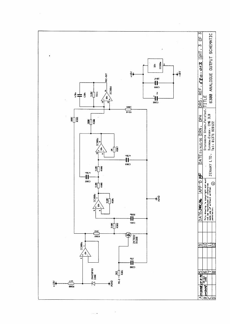
DAC Supply, +/- 10V dc supplies.+10V dc generated on the RS232 Interface, IC101, on the DisplayPCB, measure between pins 2 (positive) and 15 (0V) on IC101 onthe Display PCB.-10V dc generated on the RS232 Interface, IC101, on the DisplayPCB, measure between pins 8 (negative) and 15 (0V) on IC101 onthe Display PCB.
Jenway 6300 Ser Man 13
2.4 Signal Levels
Also see Section 7.2 - Shutter and Filter and 8.3 – EnergyLevels
All analogue signal processing is dealt with on the Detector PCB.The output from the detector is shown in the Diagnostics mode as aVoltage, in mV. For more information see Section 5.2 - DetectorCircuit and Section 7.1 – The Diagnostics Mode.
This voltage display can be used to check lamp energy (ageing),the correct functioning of the IR Stray Light filter as well as theDark Shutter.
320nm Energy, In the Diagnostics Mode (see Section 7.1Diagnostics Mode) set the wavelength to 320nm, close the DarkShutter by pressing the right arrow key. Allow the mV reading tostabilise and record the stable value.
Open the dark shutter by pressing the right arrow key and the mVreading must increase by more than 4mV from that recorded above.
If not the lamp should be changed, if it still has not improved thenthe condition and alignment of the optical components should bechecked.
Dark Current, Set wavelength to 320nm, Dark Shutter closed, IRstray light filter closed, Voltage Display should be zero +/- 6mV.
If not and no light leaks are obvious (damaged seals around samplechamber, lid not closing fully, damaged or poorly fitted caseworketc) then the detector or detector PCB may be faulty.
720nm Output, Set wavelength to 720nm, Dark Shutter open, IRstray light filter open, Voltage Display must not be greater than3600mV.
If greater than 3600mV check the lamp, lamp supply voltage, otherpower supply levels and detector PCB.
Jenway 6300 Ser Man 14
2.5 Error Codes
See also Section 3.1 and 3.2 of the Instruction Manual
A number of Error Codes are generated that relate to various faultconditions, these are detailed below with a brief description ofsome of the most common causes for these errors.
Err 1, Dark level too high during a functional calibration. Innormal operation the dark shutter closes during an operatorinstigated calibration sequence to ensure that the detector output isbelow a threshold level. The calibration is aborted and Err 1indicated if the detector output is above this threshold level. Themost likely cause is that the sample chamber door has been leftopen or was opened during the calibration sequence, it may alsooccur due to a faulty detector PCB.
Err 2, Light level too low during a functional calibration. This maybe caused by the sample/calibrant being too optically dense (dark),it may also be caused by lamp failure as well as the use of plasticor glass cuvettes at wavelengths where these materials will absorba high proportion of the light energy.
Err 3, Standard out of range in a concentration measurement. Thismay be because the standard is too optically dense at thewavelength selected or it may be too similar to the blank. Dillutionof the sample may be applicable for the former or the wavelengthfor the later method may require adjustment.
Err 4, No zero order (white) light found during wavelengthcalibration in start up routine. This error is given at the end of thewavelength calibration routine, indicating that the test was partlysuccessful (see Section 6.1 Start Up Routine). Hence this error isnormally caused by low energy levels due to lamp ageing orcontamination/deterioration of other optical components. Alsoensure that a sample or cuvette has not been left in the samplechamber during the start up tests and that there is no splashing orspillage on the exit and detector lenses.
Err 5, No zero order (white) light found during wavelengthcalibration in start up routine. This error is given during thewavelength calibration routine, indicating that even the initialthreshold level was not achieved. Possible causes are; incorrect
Jenway 6300 Ser Man 15
lamp fitted, cuvette/sample or other obstruction in the light paththrough the sample chamber as well as a possible opticalcomponent failure or misalignment.
Err 6, No dark level found in start up routine. Leaving the samplechamber open during the start up routine or opening it once theprocedure has started can cause this error. It can also indicate thefailure of the dark shutter solenoid, the solenoid drive or theassociated control circuits.
Err 7, Grating position sensor not detected. This error occursduring the wavelength calibration procedure in the start up routineand is generated at the beginning of this procedure. The grating isdriven in a clockwise direction until the attached vane breaks thepath of an opto-coupler. This is effectively the ‘end-stop’ and thepoint from which auto-calibration will always start. Failure todetect this point may be due to a faulty opto-coupler, wavelengthdrive from the power supply PCB, a faulty motor or mechanicalcoupling.
2.6 Special Key Functions
There are a number of special key functions for use by trainedengineers, do not use them unless you are fully conversant with allthe procedures these invoke.
Power On Reset. Hold the <Enter> key depressed while turningon the power. This clears the operator set parameters held in non-volatile memory and is useful in correcting many softwareconflicts. As this procedure by passes the start up routine theinstrument must be re-booted before use.
Analogue Output Calibration. Hold the <up arrow> keydepressed while turning on the power. This enables fine calibrationof the analogue output against internally generated referencevoltages. See Section 8.6.
View Start Up Routine. Hold the <Cal> key depressed whileturning on the power. This enables the detector output and gratingposition to be monitored on the display during the Start UpRoutine.
Jenway 6300 Ser Man 16
A to D Calibration. Hold the <Print> key depressed while turningon the power. This enables the A to D converter on the detectorPCB to be calibrated against an external precision voltage source.See Section 8.5.
Diagnostics Mode. Hold the <right arrow> key depressed whileturning on the power. The main display shows the signal from thedetector in mV and the resolution of the wavelength display isincreased to 0.5nm. See Section 7.1. Further special key functionsare invoked in the diagnostics mode as follows;
<right arrow> Further presses of this key will toggle the darkshutter open and closed. See Section 7.2.<left arrow > Alternate presses of this key will reduce the lampvoltage to 5V (dim) and then return it to 12V. See Section 7.3.<Cal> This key is used to set the wavelength display to 0.0 withthe grating in a position where white light (zero order) is reflectedon to the detector. A second press of this key is required to confirmthe setting before resuming the normal diagnostic functions. SeeSection 7.4.<print> Alternate presses of this key will toggle the Infra-red filterin and out of the light path. See Section 7.2.
2.7 Test Solutions1. Holmium Perchlorate – 5% w/v solution of Holmium Oxide in 1.4N
Perchloric acid, this will give absorbance maxima at 361.4, 416.1,451.1, 485.3, 536.5 and 640.5nm.
2. Potassium Dichromate – 100.0mg/l in 0.005M Sulphuric Acid (use theSulphuric Acid as the blank). This will give an Absorbance value of1.071 at 350nm.Potassium Dichromate – 50.0mg/l in 0.005M Sulphuric Acid (use theSulphuric Acid as the blank). This will give an Absorbance value of0.536 at 350nm.
3. Sodium Nitrate – 50g/l in deionised water, should give less than 0.1%Transmittance at 340nm.
All these solutions are hazardous and the manufacturer/supplierssafety precautions should be carefully followed at all times inpreparation, use and storage.

Jenway 6300 Ser Man 17
Section 3
System Description
3.1 Background
3.2 Sub-Assemblies
3.3 Accessories
3.4 Outputs
Jenway 6300 Ser Man 18
3.1 Background
The model 6300 is a single beam, visible spectrophotometer withAbsorbance, Transmission and Concentration measurement modes.It is a direct replacement for the earlier model 6100.
This manual covers the service, maintenance and repair of all unitswith a serial number greater than 5000. For the service,maintenance and repair of units with serial numbers less than 5000please refer to the 6300 Mark 1 Service Manual.
3.2 Sub-Assemblies
The model 6300 spectrophotometer can easily be broken down intosub-assemblies for the purposes of repair or replacement. All thePCBs are easily removed, see Section 8.2 – Dismantling. Themonochromator is also a replaceable sub-assembly. There is arange of sampling accessories that can be easily fitted and removedfrom the sample chamber.
See Section 2.2 for details of the main sub-assemblies and Section11 for details of other spare parts. The following paragraph lists thesampling accessories available.
3.3 Accessories
The following sampling accessories are available, where necessaryadditional service information for these accessories is available onrequest. The development of other sampling accessories iscontinuous, please check current brochures or www.jenway.com for up-to-date information.
632 001 External Sipper Pump (230V)632 031 External Sipper Pump (115V)634 001 4 Position Cell Changer630 020 Test Tube Holder (13mm diameter)630 021 Test Tube Holder (25mm diameter)630 022 Test tube Holder (16mm diameter)630 005 20 to100mm Single Cell Holder648 001 Water Heated Single Cuvette Holder
Jenway 6300 Ser Man 19
Other accessories include:
543 001 External 40 Column Printer542 009 Interface Cable Kit630 028 Dust Cover037 201 Water/refrigerant Circulator for use with 648 001
3.4 Outputs
The 6300 has both analogue and RS232 outputs.
Details of the level of the analogue output for the different rangesthat may be selected on the instruments is given in Section 6.3 ofthe Instruction Manual.
Pin configuration for the RS232 socket is given in Section 6.2 ofthe Instruction Manual. Section 6.1 of the Instruction Manual givesdetails of the various ASCII codes that may be transmitted to the6300 to enable complete remote control from a terminal or PC.
Jenway 6300 Ser Man 20
Section 4
Optical Description
4.1 Light Source
4.2 Grating
4.3 Shutter and Filter
4.4 Signal Detector
Jenway 6300 Ser Man 21
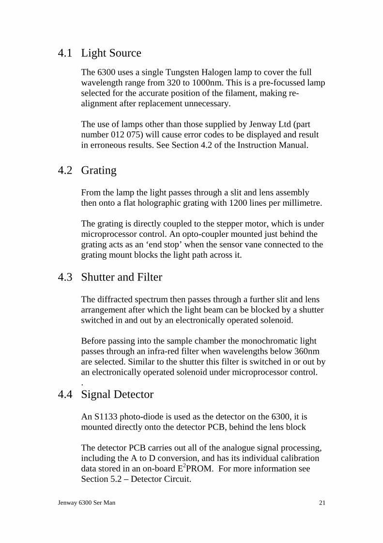
4.1 Light SourceThe 6300 uses a single Tungsten Halogen lamp to cover the fullwavelength range from 320 to 1000nm. This is a pre-focussed lampselected for the accurate position of the filament, making re-alignment after replacement unnecessary.
The use of lamps other than those supplied by Jenway Ltd (partnumber 012 075) will cause error codes to be displayed and resultin erroneous results. See Section 4.2 of the Instruction Manual.
4.2 Grating
From the lamp the light passes through a slit and lens assemblythen onto a flat holographic grating with 1200 lines per millimetre.
The grating is directly coupled to the stepper motor, which is undermicroprocessor control. An opto-coupler mounted just behind thegrating acts as an ‘end stop’ when the sensor vane connected to thegrating mount blocks the light path across it.
4.3 Shutter and Filter
The diffracted spectrum then passes through a further slit and lensarrangement after which the light beam can be blocked by a shutterswitched in and out by an electronically operated solenoid.
Before passing into the sample chamber the monochromatic lightpasses through an infra-red filter when wavelengths below 360nmare selected. Similar to the shutter this filter is switched in or out byan electronically operated solenoid under microprocessor control..
4.4 Signal Detector
An S1133 photo-diode is used as the detector on the 6300, it ismounted directly onto the detector PCB, behind the lens block
The detector PCB carries out all of the analogue signal processing,including the A to D conversion, and has its individual calibrationdata stored in an on-board E2PROM. For more information seeSection 5.2 – Detector Circuit.
Jenway 6300 Ser Man 22
Section 5
Electronic Description
5.1 Power Supplies
5.2 Detector Circuit
5.3 Microprocessor and Display
Jenway 6300 Ser Man 23
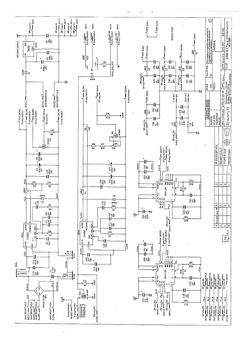
5.1 Power Supplies
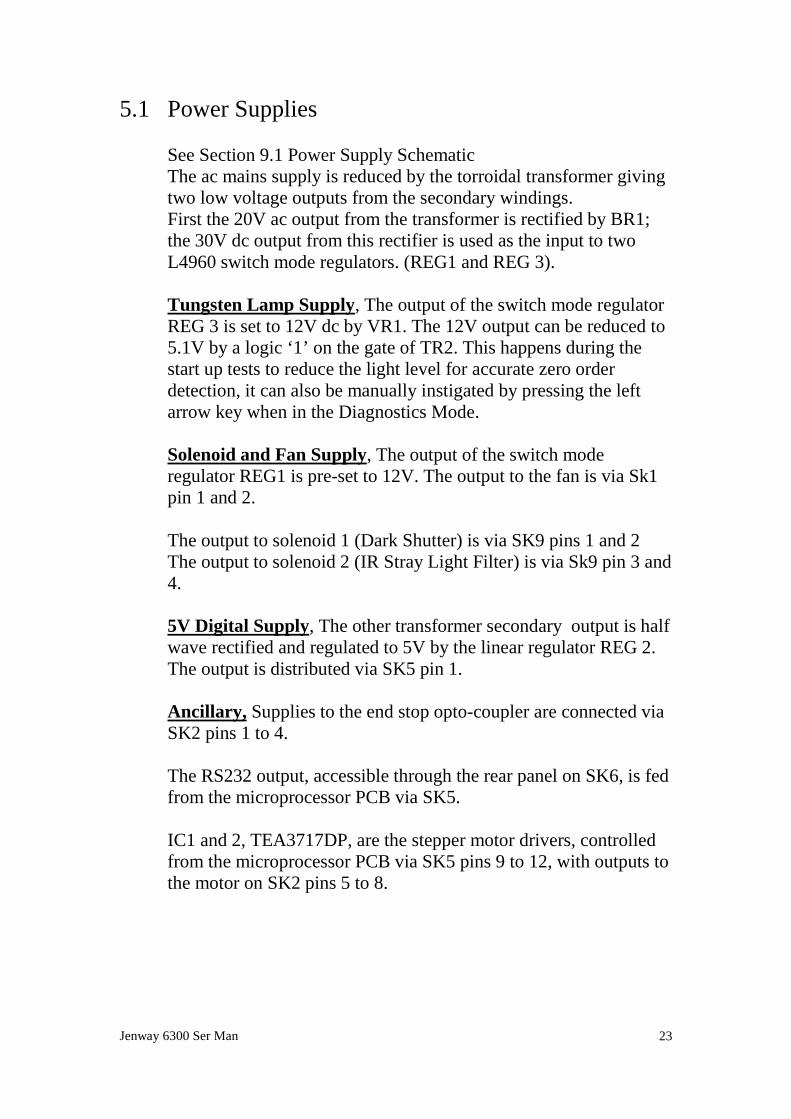
See Section 9.1 Power Supply SchematicThe ac mains supply is reduced by the torroidal transformer givingtwo low voltage outputs from the secondary windings.First the 20V ac output from the transformer is rectified by BR1;the 30V dc output from this rectifier is used as the input to twoL4960 switch mode regulators. (REG1 and REG 3).
Tungsten Lamp Supply, The output of the switch mode regulatorREG 3 is set to 12V dc by VR1. The 12V output can be reduced to5.1V by a logic ‘1’ on the gate of TR2. This happens during thestart up tests to reduce the light level for accurate zero orderdetection, it can also be manually instigated by pressing the leftarrow key when in the Diagnostics Mode.
Solenoid and Fan Supply, The output of the switch moderegulator REG1 is pre-set to 12V. The output to the fan is via Sk1pin 1 and 2.
The output to solenoid 1 (Dark Shutter) is via SK9 pins 1 and 2The output to solenoid 2 (IR Stray Light Filter) is via Sk9 pin 3 and4.
5V Digital Supply, The other transformer secondary output is halfwave rectified and regulated to 5V by the linear regulator REG 2.The output is distributed via SK5 pin 1.
Ancillary, Supplies to the end stop opto-coupler are connected viaSK2 pins 1 to 4.
The RS232 output, accessible through the rear panel on SK6, is fedfrom the microprocessor PCB via SK5.
IC1 and 2, TEA3717DP, are the stepper motor drivers, controlledfrom the microprocessor PCB via SK5 pins 9 to 12, with outputs tothe motor on SK2 pins 5 to 8.
Jenway 6300 Ser Man 24
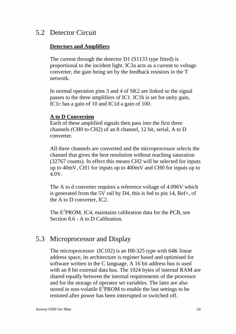
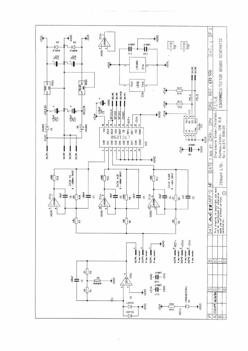
5.2 Detector Circuit
Detectors and Amplifiers
The current through the detector D1 (S1133 type fitted) isproportional to the incident light. IC3a acts as a current to voltageconverter, the gain being set by the feedback resistors in the Tnetwork.
In normal operation pins 3 and 4 of SK2 are linked so the signalpasses to the three amplifiers of IC1. IC1b is set for unity gain,IC1c has a gain of 10 and IC1d a gain of 100.
A to D ConversionEach of these amplified signals then pass into the first threechannels (CH0 to CH2) of an 8 channel, 12 bit, serial, A to Dconverter.
All three channels are converted and the microprocessor selects thechannel that gives the best resolution without reaching saturation(32767 counts). In effect this means CH2 will be selected for inputsup to 40mV, CH1 for inputs up to 400mV and CH0 for inputs up to4.0V.
The A to d converter requires a reference voltage of 4.096V whichis generated from the 5V rail by D4, this is fed to pin 14, Ref+, ofthe A to D converter, IC2.
The E2PROM, IC4, maintains calibration data for the PCB, seeSection 8.6 - A to D Calibration.
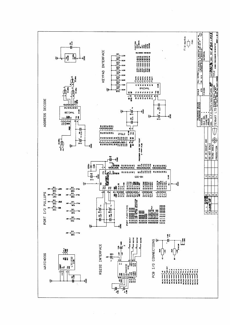
5.3 Microprocessor and DisplayThe microprocessor (IC102) is an H8-325 type with 64K linearaddress space, its architecture is register based and optimised forsoftware written in the C language. A 16 bit address bus is usedwith an 8 bit external data bus. The 1024 bytes of internal RAM areshared equally between the internal requirements of the processorand for the storage of operator set variables. The later are alsostored in non-volatile E2PROM to enable the last settings to berestored after power has been interrupted or switched off.
Jenway 6300 Ser Man 25
The operating system software is stored in the 64K by 8 bitEPROM, IC106. This will have a label attached identifying thesoftware version and date it was programmed. Removal of thislabel may damage the component and will invalidate the warranty.
IC103 is a 3 to 8 line address decoder that can select the peripheraldevices on the data bus, being the keypad interface through IC104or the display driver IC200.
The watchdog circuit (IC100) monitors the activity of theprocessor, while IC101 generates the correct levels for the RS232output. The four amplifiers in IC300 form the D to A converterwhich generates the analogue output.
Jenway 6300 Ser Man 26
Section 6
Software and Operation
6.0 Warning
6.1 Start Up Routine
6.2 Photometrics
6.3 Concentration
Jenway 6300 Ser Man 27
6.0 Warning
This section gives an overview of the software functions, it is notmeant to be a detailed analysis of the software routines or code. Itmust not be treated as a substitute Instruction Manual, its purposeis to enable basic navigation through the operation and set up of the6300 spectrophotometer sufficient to verify basic operation.
6.1 Start Up Routine
When the power to the unit is switched on a self-test routine isactivated. During these start-up tests the following parameters arechecked and must be passed before operation can continue:
Dark Level Test: - The light beam is blocked by the dark shuttersolenoid switching in. This test checks that the output of thedetector is below a threshold level when there is no light falling onit. The test will be failed if the sample chamber lid is left openduring the start up routine, if the dark shutter (solenoid 1) is faulty(electrical or mechanical) or if the Detector or Detector PCB isfaulty.
Wavelength Calibration: - This test checks for the zero order(white) light that is reflected through the sample chamber when thegrating is in a position where it acts as a mirror. Each time the unitis switched on this position is used as a physical reference pointagainst which the stored wavelength calibration data is applied.
This test is carried out in the following manner; the microprocessorinstructs the grating to drive to its minimum value of –200nm. Thisshould ensure that the vane attached to the grating mount breaksthe light path of the opto-coupler mounted on the monochromatorbase plate that is set at a position of approximately –50nm.If it does not receive a signal from the opto-coupler then error codeErr 7, grating position sensor not detected, is returned when themotor stops.
In correct operation a signal is returned when the vane reaches theopto-coupler. Then the microprocessor instructs the grating torotate in the reverse direction, in 1nm, steps for 200nm, or until asignal greater than 200mV is returned from the detector (this level,
Jenway 6300 Ser Man 28
with the lamp dimmed can only be produced by the white zeroorder light). If this 200mV level can not be achieved then thegrating stops after having rotated the 200nm and an error code Err5, no peak light level found, is returned.
In correct operation when this 200mV level is detected the gratingrotates in the same direction for a further 200nm but in 0.5nmsteps. For each step an increasing output is returned until the peakis reached. The grating is stopped when a decrease in output ismeasured and by reversing again for one step the position of thepeak is verified. If the grating rotates the full 200nm without theoutput increasing and then falling the error code Err 4, no zeroorder peak found, is returned.
This test will be failed if samples or cuvettes etc are left in thesample compartment during the start up routine, if the sampleholder or sampling device in the sample chamber is incorrectlyfitted/aligned such that it obscures the light beam. Also if theincorrect lamp is fitted, if the lamp has not been fitted correctly, ifthe dark shutter is (stuck) in the closed position or throughcontamination, degradation or misalignment of other opticalcomponents.
6.2 Photometrics
When the Start Up test has been successfully completed the displayreturns to the last settings of wavelength and mode used before theinstrument was turned off.
The wavelength displayed on the lower digital display can beadjusted by using the up and down arrow keys to select the valuesuitable for a specific application.
The cursor can be moved along the menu bar at the bottom of thescreen by using the right and left arrow keys.
Moving the cursor under the %T icon will enable the Transmissionmeasurement mode, similarly moving it under the ABS icon willenable the Absorbance measurement mode. These two modes arecalibrated by simply inserting a cuvette or test tube containing ablank solution in the sample chamber, closing the lid and pressingthe CAL pushbutton. The CAL icon on the display will flash while
Jenway 6300 Ser Man 29
the calibration sequence is in progress; when it stops the maindigital display will be set to 100.0 %T or 0.000 ABS automatically.
Sample measurement can then be carried out by inserting a cuvetteor test tube containing the sample solution into the samplechamber, closing the lid and recording the value on the maindisplay.
6.3 ConcentrationMoving the cursor under the CONC icon on the bottom menu barenables the concentration measurement mode.
NOTE:- Before selecting this mode a blank calibration must becarried out in the Absorbance mode at the wavelength to beused for the concentration measurement.
When the concentration mode is selected two further icons, xF andUNITS, appear on the bottom menu bar.
A linear relationship between Absorbance and Concentration isassumed for all measurements. This enables concentrationmeasurements to be made against a standard solution (CONCmode) or by entering a factor which adjust the slope of the straight-line relationship (xF mode). The latter is also often used to improvethe sensitivity of comparative colour measurements in a number ofInternational Standard Methods, as in beer colour measurements toEBC standards etc.
A range of units can be displayed against the top digital(Concentration) display. The required units can be selected bymoving the cursor, with the right or left arrow keys, along thebottom menu bar until it is under the UNITS icon. The Up or Downarrow keys can then be used to display in turn ppm, mg/l, g/l, M, %or blank (no units displayed). When the required unit is displayedsimply move the cursor back to xF or CONC)
To calibrate the concentration range against a known standardmove the cursor beneath the CONC icon using the right or leftarrow keys. Insert a cuvette or test tube containing the knownstandard solution into the sample chamber, close the lid and pressthe CAL key. The CAL icon on the display will flash and the up or
Jenway 6300 Ser Man 30
down arrow keys can be used to adjust the value displayed on theupper digital display to the actual value of the standard being used.When this value has been set a further press of the CAL keycompletes the calibration against this standard solution. Cuvettes ortest tubes containing samples can then be inserted in the samplechamber, the sample chamber lid closed and readings taken directlyfrom the display.
During the above calibration procedure the software calculates thefactor required to multiply the Absorbance by to achieve the linearrelationship with the concentration of the standard used. The Factor(xF) mode is automatically updated with this value which can beviewed by moving the cursor, using the right or left arrow keys,along the bottom menu bar until it is under the xF icon. For futureassays this factor could be used instead of the standard solution butgood practice and standard operating procedure (sop) should beobserved and the accuracy of this factor be verified on a regularbasis.
If a factor is known or supplied in a sop then this can be entereddirectly in the Factor (xF) mode by moving the cursor, using theright or left arrow keys, along the bottom menu bar until it is underthe xF icon. The up or down arrow keys can then be used to adjustthe value of the factor on the lower digital display from 0 to 9999,when the correct value has been set move the cursor back under theCONC icon using the left arrow key. Cuvettes or test tubescontaining samples can then be inserted in the sample chamber, thelid closed and readings taken directly from the display.
Jenway 6300 Ser Man 31
Section 7
Diagnostics
7.1 The Diagnostics Mode
7.2 Shutter and Filter Control
7.3 Lamp Control
7.4 Zero Order Calibration
Jenway 6300 Ser Man 32
7.1 The Diagnostics Mode
The Diagnostics mode is accessed using the following Special Keyfunction, hold down the right arrow key <>> while turning thepower on. The main display now shows the linearised signal fromthe detector in mV and the resolution of the wavelength display hasincreased to 0.5nm.
7.2 Shutter and Filter Control
Once the diagnostics mode has been activated further presses of theright arrow key <>> will toggle the dark shutter alternatelybetween the open and closed positions. With the covers still on theinstrument the actual position of the dark shutter can be determinedby the main display that will in general have a very low (zero)reading when the shutter is closed and a very high reading whenthe shutter is open.
Once the diagnostics mode has been activated alternate presses ofthe print key will toggle the Infra-red filter in and out of the lightpath. A similar effect to the above can be used to determine theactual position of the filter when the instrument covers are in place;of course the difference between the ‘in’ and ‘out’ readings will begreater at higher wavelengths.
7.3 Lamp Control
Once the diagnostics mode has been activated alternate presses ofthe left arrow key (<<>) will reduce the lamp voltage to 5V (dim)and then return it to 12V. This function is automatically used in thestart up tests to accurately detect the zero order position. For safetyreasons it should also be used at all times when working on theinstrument with any covers removed such that the lamp is exposed.
7.4 Zero Order Calibration
Warning;-This procedure can be used to re-set the stored wavelengthcalibration data, so a new wavelength calibration must be carried
Jenway 6300 Ser Man 33
out after this procedure has been used. Also see Section 8.3 OpticalAlignment
1 Press the right arrow key [>] while turning the power switch on.
2 The display should show a mV reading on the top row, followed bythe wavelength on the 2nd row and %T at the bottom left hand side.
3 Pressing the right arrow key again [>] should operate the darkshutter solenoid. Press this key to ensure that the shutter is in theopen position (the position that gives a maximum reading on thedisplay)
4 Press the down arrow key until the wavelength display reads 0.0.Press the left arrow key to dim the lamp.
5 Use the up and down arrow keys to move in 0.5nm steps either sideof zero and identify at which wavelength a peak mV reading isobtained. Note this reading.
6 Pressing the CAL key will re-set this reading to zero and the CALsymbol on the display will flash. While it is flashing carry out step7 or step 8.
7 Pressing the CAL key again will clear the wavelength displayoffset noted in step 5 to zero.
8 The offset noted in step 5 (or an alternative correction, see Section8.5 Wavelength Calibration) can be entered before pressing theCAL key by using the up or down arrows to set the display to therequired offset.
9 If step 7 was used a wavelength calibration must be carried out; inboth cases a performance verification as detailed in Section 8.8must be carried out.
Jenway 6300 Ser Man 34
Section 8
Maintenance
8.1 Routine Maintenance
8.2 Dismantling
8.3 Optical Alignment
8.4 Energy Levels
8.5 Wavelength Calibration
8.6 A to D Calibration
8.7 D to A Calibration
8.8 Performance Verification

Jenway 6300 Ser Man 35
8.1 Routine Maintenance
The Jenway Limited, Model 6300 Spectrophotometer has beendesigned to give optimum performance with minimal maintenance.It is only essential to keep the external surfaces clean and free fromdust and to ensure that the area around and underneath the unit isalso clean and dust free.
The sample area should be kept clean and accidental spillageshould be wiped away immediately as some corrosive or solventbased samples or standards may attack the materials used in thesample chamber and cell holders.
To give added protection when not in use the unit should bedisconnected from the mains supply and covered with the optionaldust cover (630 028). For longer term storage it is recommendedthat the unit be returned to the original carton, for re-shipment afurther external packing case suitable for the method of carriageshould be used.
Details of all routine maintenance tasks, including changing thelamp can be found in Section 4 of the Instruction Manual.
8.2 Dismantling
Before dismantling any of the following sub-assemblies ensure thatthe unit is switched off and the power cable is disconnected fromthe supply
Do not attempt to dismantle these units unless they are in a clean,dry and dust free environment.
Use a soft lint free cover on any benches that will have casework,displays or keypads placed on them.
Use approved and tested anti-static procedures when dismantlingany electronic sub-assembly or PCB and store these items in anti-static containers where necessary.
General – Access to all major sub-assemblies can easily be gainedby removing the top half of the case. Access to the lamp housingcan be made through the lamp access panel on the rear of the unit.
Jenway 6300 Ser Man 36
The sampling accessory can be accessed through the samplechamber lid.
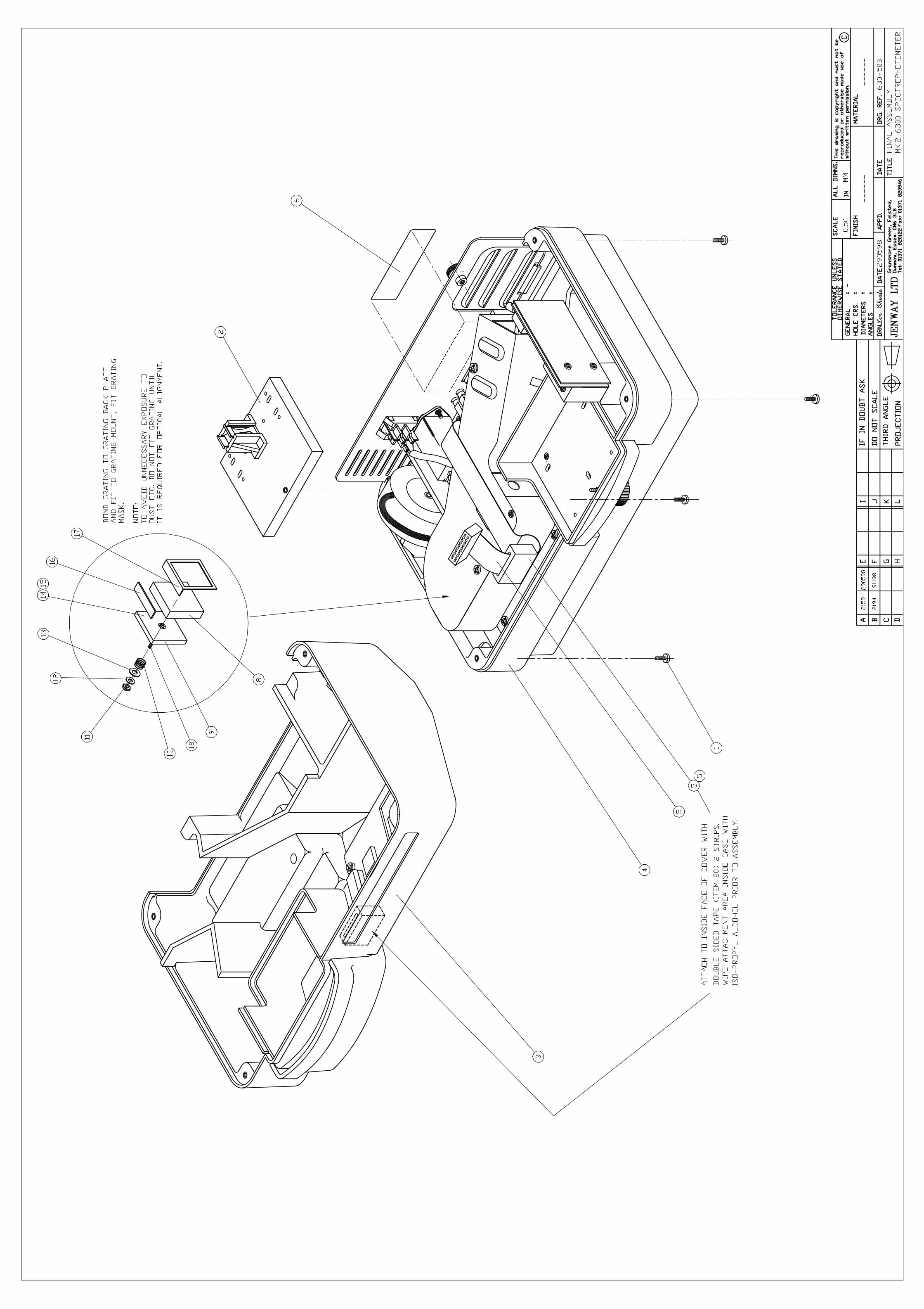
Top/Bottom Case Assemblies – The top and bottom caseassemblies can easily be separated by unscrewing the four recessedscrews in each corner of the base. This should be done withoutinverting the unit, by moving it forward over the front edge of thebench to unscrew the front two screws, and then turning it aroundto do the same with the back two. Turn it back round and then thetop half of the case can be lifted off the bottom half take care not tostrain any cables between the top and bottom sections.
Should it be necessary to work on the top case assembly by itself itis simply a matter of disconnecting the plug from SK5 on thepower supply PCB then the top can be completely removed.
Microprocessor/Display PCB The microprocessor/display PCB ismounted in the top case assembly. To remove it disconnect SK1 onthe ribbon cable to SK5 and PL106 to the membrane keypad.Unscrew the four screws and the PCB can be removed. The displaymodule and microprocessor PCB should be treated as a pair andreplaced together. Removing the display from the PCB should notbe attempted.
Detector PCB The detector PCB is mounted vertically at the farright hand side of the lower chassis. It is easily removed byunscrewing the two screws recessed in the top of the metalmounting block. SK4 on the power supply PCB should be removedand the ribbon cable pulled back under the monochromator (it maybe necessary to lift the monochromator to complete this task).Remove the two screws and spacers that hold the lens block, takecare not to rotate it as the detector is mounted in a recess inside theblock and can easily be broken off. Remove the last screw with itsnut and washer to enable the electrostatic screen to be removedfrom the PCB.
The Detector PCB stores detailed calibration data relating to theoptics of the unit it is fitted in, replacing the detector PCB withouta full re-calibration will invalidate the quoted specification.
Monochromator The monochromator is located across the front ofthe lower case. It is a sealed unit and breaking the seals will
Jenway 6300 Ser Man 37
invalidate the warranty. Before proceeding with replacementensure the unit is in a clean, dust and humidity free area.
Remove the four screws from the base plate, two at the front, oneat the far right hand side in front of the detector PCB the other onthe far left hand side. Carefully lift the monochromator assemblyunplugging the connectors SK1 and SK9 without straining thecables. The monochromator can now be removed.
Replacement is the reverse of dismantling, but ensure that allcables are carefully fitted in the appropriate recesses so that theyare not crushed when screwing the unit down. When fitting areplacement unit ensure a full calibration is run so that the newcalibration data for the new monochromator is stored. (See Section8.5, 8.4 and 8.7)
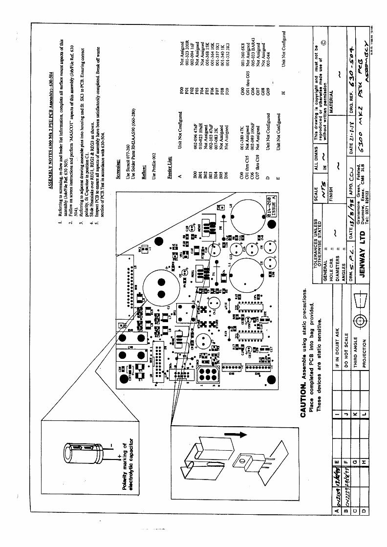
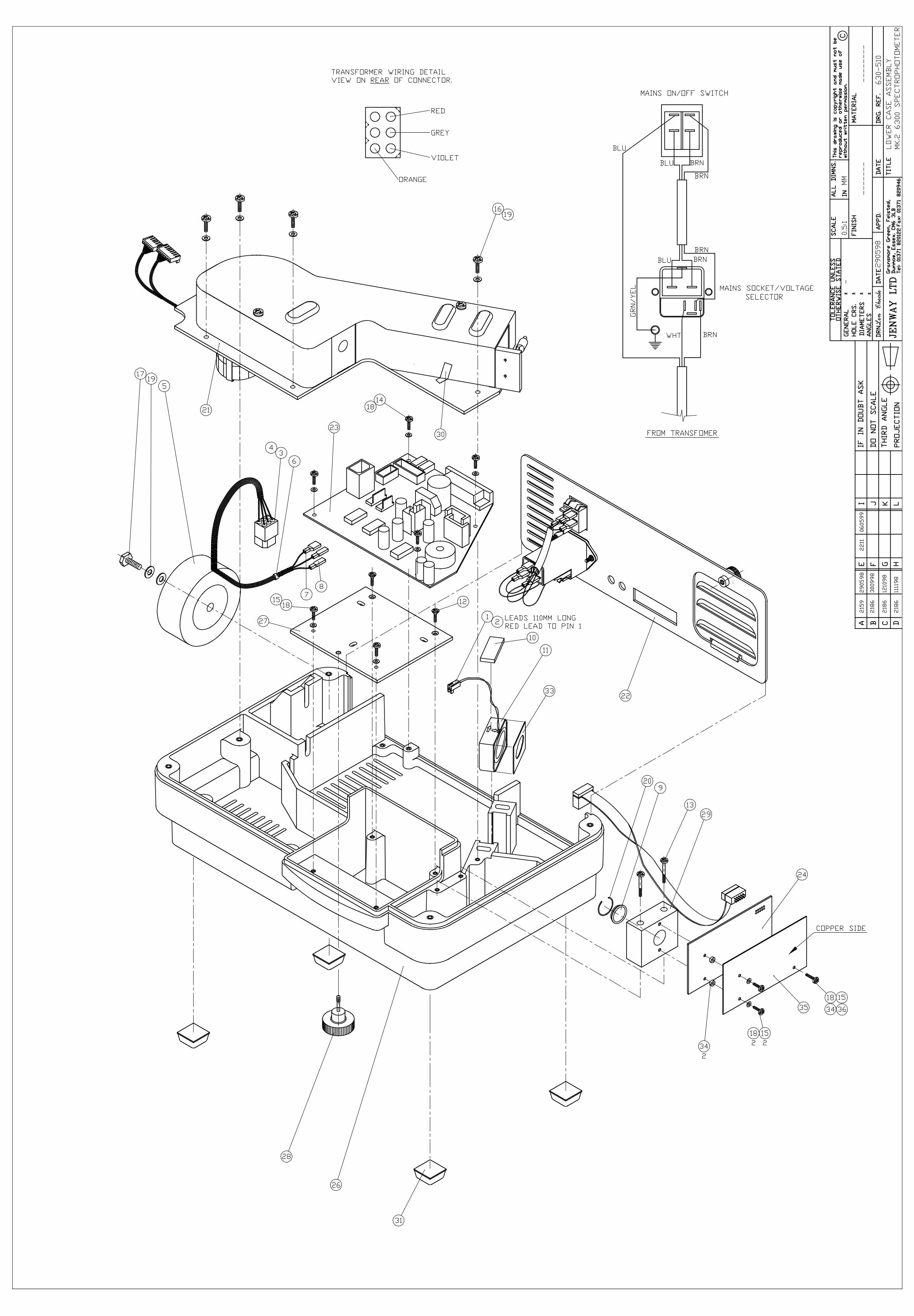
Power Supply PCB With the monochromator removed as abovethe power supply PCB is easily removed by undoing the fourscrews holding it to the lower case assembly. SK3 to thetransformer and SK1 to the fan should be removed before lifting itout of the lower case.
Cooling Fan Carry out the above procedures to enable the fan tobe lifted out of its recess in the lower case. Ensure the position ofthe retaining spring and the direction of the airflow are noted forre-assembly.
Transformer Remove SK3 from the power supply PCB and thepush on connectors for the cables that go to the mains switch andinlet filter assembly. Then remove the transformer by undoing thesingle bolt through the centre that holds it to the moulded bracketin the base assembly.
8.3 Optical Alignment
This procedure can irreversibly affect the performance andoperation of the instrument. Please read the following warningsand request help or clarification before proceeding.
Carrying out this procedure will invalidate the manufacturersoptical performance specification and should only be
Jenway 6300 Ser Man 38
undertaken by personnel trained and equipped to verify theoptical performance of the instrument.
Instrument covers should only be removed by engineerstrained in safe working practices and aware of electric shockhazards. Removal of the monochromater cover will invalidateany warranty claim regarding performance to specification.
Do not look directly at the light source, use eye protection orthe lamp dimming function when necessary. Do not touch anyoptical surfaces.
If in any doubt DO NOT PROCEED.
Ensure or verify by replacement that a GENUINE JENWAYLAMP is fitted, (refer to the instruction manual for details).There are many lamps that look similar but the filamentposition is critical and can only be guaranteed on Jenwaylamps, replacing the lamp may correct the problem withoutany further re-alignment.
1 Remove the top half of the case by undoing the four recessedscrews in the corners of the base.
2 Place the top half of the case behind the base taking care not to trapor strain the connecting cables.
3 Remove the two screws retaining the black monochromator coverin the bottom half of the case. Remove the cover and place to oneside. DO NOT TO TOUCH ANY OPTICAL COMPONENTS.
4 Taking all precautions to avoid the risk of electric shock, connectthe power cable and depress the right arrow key [>] while turningthe power switch on.
5 The display should show a mV reading on the top row, followed bythe wavelength on the 2nd row and %T at the bottom left hand side.
6 Pressing the right arrow key again [>] should operate the solenoidin front of the exit slit assembly. Press this key to ensure that theshutter is in the open position (light is passing through the exit slit)
Jenway 6300 Ser Man 39
7 Pressing the left arrow key will dim the light source. This shouldalways be done when looking at or towards the light source. Fornow ensure it is pressed to give maximum light output.
8 Follow the light path from the lamp through the entrance slitassembly on to the grating. Use a narrow strip of white card to helpshow the position and shape of the light beam. DO NOT TOUCHANY OPTICAL COMPONNENTS.
9 Move the card in an arc in front of the grating from the exit slitassembly, through the incident light beam and towards the torroidaltransformer at the back of the instrument.
10 While doing this identify the bright coloured spectrum (1st order),the white incident light beam, the white zero order light beam, andthen the dimmer coloured spectrum (2nd order).
11 Press the up or down arrow key to move the white zero order lightbeam towards the exit slit. (Usually the down arrow key). Thewavelength displayed should be seen to decrease towards zero.
12 Keep pressing the down (or up) arrow key until the white zeroorder light is positioned exactly and symmetrically across the exitslit.
13 Press the print key to switch the Infra-red filter out of the light pathand check, using the white card that this light passes the samplechamber and onto the detector lens.
14 With the zero order light passing through the sample area onto thedetector press the <CAL> key twice and ensure that thewavelength display reads zero.
15 Replace the black monochromator cover, tighten the two retainingscrews and place the top half of the case on the base taking care notto trap any cables.
16 Press the up and down arrow keys and check to see if the mVreading can be increased as the wavelength changes. If the displaygoes over-range (1. ) Press the left arrow key to reduce the lampbrightness.
Jenway 6300 Ser Man 40
17 If a peak mV reading can be obtained within +/- 2nm of the zeropoint calibrated by this procedure then press the <CAL> key twicewhen this peak mV reading is obtained. If the peak reading isobtained at a wavelength greater than +2nm or less than –2nm thenthe above alignment procedure should be repeated. When OKreplace the four screws in the base section.
18 A wavelength calibration must now be carried out (see Section 8.5)and then a full performance verification as detailed in Section 8.8.
Grating Position Sensor
Operation and adjustment can be checked and carried out as follows;
Remove the top half of the case by undoing the four recessed screws inthe corners of the base.
Place the top half of the case behind the base, taking care not to trap orstrain the connecting cables.
Taking all precautions to avoid the risk of electric shock, connect thepower cable and depress the right arrow key [>] while turning the powerswitch on.
The display should show a mV reading on the top row, followed by thewavelength on the 2nd row and %T at the bottom left hand side.
Connect the positive lead of a voltmeter to the anode of D4 on the powersupply PCB and the negative lead to the black analogue output socket onthe rear panel. (The anode of D4 is the contact close to SK3 that is alsoconnected to the plate through hole between D4 and SK3). Select a rangesuitable for measuring up to 5V dc.
Press the down arrow key to reduce the wavelength to –30nm, thevoltmeter should read approximately 0.100V, Press the down arrow keyagain to reduce the wavelength to –40nm, the voltmeter should still readapproximately 0.100V.
Press the down arrow key again to reduce the wavelength to –50nm, thevoltmeter should now read approximately 5.00V. Press the up arrow keyand return the wavelength setting to –40nm and the voltmeter readingshould return to approximately 0.100V.
Jenway 6300 Ser Man 41
Should these results not be obtained the function of the opto-couplershould be checked, this can be carried out as follows;
Remove the monochromator cover observing all the previously statedprecautions. Press the up arrow key to select a wavelength about 500nmand check that the grating rotates correctly.
Pass a piece of thick paper or card between the ‘jaws’ of the opto-couplerand check that when the card is inserted a voltage of approximately 5.00Vis measured as above and that when it is removed this voltage drops toapproximately 0.100V.
If these results are correct then the position should be adjusted as below,if not then the opto-coupler or power supply PCB may be faulty. Theremay also be a bad connection between them. Check the wiring to SK2and that no wires are trapped under the monochromator.
To adjust the position press the down arrow key to set the wavelength to–50nm, slacken the two fixing screws slightly and adjust the position ofthe opto-coupler until the voltmeter reading just changes from 0.100V to5.00V.
Tighten the screws and check that at –40nm the reading is approximately0.100V and that at –50nm it is approximately 5.00V. If not repeat asabove.
8.4 Energy Levels
Equipment Required; - None, checked against internal settings.
Before proceeding with any calibration it is essential to ensure the correctfunctioning of the optical system, this can be done very easily in theDiagnostics mode (see Section 7) where the following performanceshould be obtained.
All analogue signal processing is dealt with on the Detector PCB. Theoutput from the detector is shown on the Diagnostics Screen as a Voltage,in mV. For more information see Section 5.3 - Detector Circuit andSection 7.1 – The Diagnostics Mode.
This voltage display can be used to check lamp energy (ageing), thecorrect functioning of the IR Stray Light filter as well as the Dark Shutter.
Jenway 6300 Ser Man 42
320nm Energy, In the Diagnostics Mode (see Section 7.1 DiagnosticsMode) set the wavelength to 320nm, close the Dark Shutter by pressingthe right arrow key. Allow the mV reading to stabilise and record thestable value.
Open the dark shutter by pressing the right arrow key and the mV readingmust increase by more than 4mV from that recorded above.
If not the lamp should be changed, if it still has not improved then thecondition and alignment of the optical components should be checked.
Dark Current, Set wavelength to 320nm, Dark Shutter closed, IR straylight filter closed, Voltage Display should be zero +/- 6mV.
If not and no light leaks are obvious (damaged seals around samplechamber, lid not closing fully, damaged or poorly fitted casework etc)then the detector or detector PCB may be faulty.
720nm Output, Set wavelength to 720nm, Dark Shutter open, IR straylight filter open, Voltage Display must not be greater than 3600mV.
If greater than 3600mV check the lamp, lamp supply voltage, other powersupply levels and detector PCB.
8.5 Wavelength Calibration
Equipment Required; - A certified wavelength standard, i.e. HolmiumOxide Filter, Holmium Perchlorate Solution etc. (See Section 8.8.1)
Wavelength calibration can be carried out in the Diagnostics Mode usingthe wavelength (zero order) offset function. Do not carry out thefollowing procedure without a suitable, certified wavelength calibrationstandard.
Turn the unit on and allow the Start Up tests to complete.
Use the up and down arrow keys to select a wavelength about 10nmbelow the certified wavelength of the filter or standard to be used.
Select the absorbance or transmission modes, using the right or left arrowkeys, depending on whether an Absorbance or transmittance standard orfilter is being used.
Jenway 6300 Ser Man 43
Press the CAL key to set the display to 0.000ABS or 100%T. Insert thefilter or standard in the sample chamber and close the lid.
Press the up arrow key to increase the wavelength by 1nm and check thatan Absorbance value has increased or a Transmission value hasdecreased.
Repeat the above until the first Absorbance value decreases or the firstTransmission value increases. At this point press the down arrow key andcheck that the previous value is attained again. Then record thiswavelength as the reported peak.
Repeat the above and check that the same value is reported.
NOTE: 1.) If it is known that there are other peaks closer than 10nmto the certified peak then the start wavelength should be moved closer tothe certified peak just past any others.
2.) If the Absorbance display goes over range during the testthen carry out the Calibration at the initial wavelength with the filter orstandard in the sample chamber.
Calculate the adjustment required to correctly align the reported figurewith the certified value from the following...
Certified Value – Reported Value = Correction factor (can be negative orpositive, maximum correction permissible is 3.0nm)
Switch the unit off and re-start it in the Diagnostics Mode by holdingdown the right hand arrow key <>> while turning power on.
The display should show a mV reading on the top row, followed by thewavelength on the 2nd row and %T at the bottom left hand side.
Pressing the right arrow key again [>] should operate the dark shuttersolenoid. Press this key to ensure that the shutter is in the open position(the position that gives a maximum reading on the display)Press the down arrow key until the wavelength display reads 0.0. Pressthe left arrow key to dim the lamp.
Use the up and down arrow keys to set the display to the correction factorcalculated above (observe polarity)
Jenway 6300 Ser Man 44
Pressing the CAL key again will enter this value into memory as the newwavelength calibration offset.
Switch the unit off and then on again, allowing the Start Up tests to becompleted, re-check the certified wavelength calibration standard asabove and check that the reported value is now correct.
8.6 A to D Calibration
The A to D converter should only be calibrated by engineers who havebeen trained on this aspect of servicing by Jenway Limited.
Equipment Required; - A certified voltage calibrator with a resolutionof 0.1mV and a range up to at least +/-4.0000V.A lead for connecting the calibrator to pins 1 (negative) and pin 3(positive) of SK2 on the detector PCB. (8 pin Molex type connector)
Access the Detector PCB by removing the top case assembly as describedin Section 8.2 - Dismantling.
Remove the jumper from pins 3 and 4 on SK2 on the Detector PCB andfit the lead connected to the calibrator.
Switch the calibrator on and select a negative output (or reverse thecontacts)
Select the A to D calibration mode by turning the unit on with the Printkey depressed.
The lower display will change to prompt for specific input levels and theupper display will show the relevant mV output.
The initial prompt is for –1mV, set the calibrator to give an input signalof –1mV, let the upper display settle and then press the enter key.
Then the prompt changes to –20mV, set the calibrator to –20mV let theupper display settle and then press the enter key.
Continue responding to the prompts in this way for –39mV, -200mV, -390mV, -2000mV and –3900mV. Note that the –39mV and –
Jenway 6300 Ser Man 45
390mV levels are repeated as these are the cross over points from onechannel to the next.
When successfully completed the display returns to the last settings usedin the measurement mode.
8.7 D to A Calibration
Equipment required; - Voltmeter capable of reading 2.0V with aresolution of 1mV.
The D to A calibration sets the levels of the analogue output. This iscarried out with the on-board voltage reference at zero and +/- 2000mV.
Select the D to A calibration mode by holding the up arrow depressedwhile the power is turned on.
The upper display will show ‘dAC mV’ and the lower display willindicate the mV level that should be available on the Analogue output.
Connect a voltmeter to the analogue output on the rear panel. Select arange that will display 2000mv to 0.1mV resolution.
The first prompt indicates an output level of -2000mV, use the up anddown and left and right arrow keys to adjust the actual reading on thevoltmeter to –2000mV.
The left and right arrow keys change the output in 5mV steps, the up anddown arrow keys in 0.5mV steps.
When the correct level is reached press the enter key and the promptmoves on to 0mV, repeat the above for this and the 2000mV levels.
When successfully completed the display returns to the last settings usedin the measurement mode.
Jenway 6300 Ser Man 46
8.8 Performance VerificationEquipment Required; - 1. Certified Wavelength Standard,2. Certified Absorbance Standards, 3. Certified Stray LightStandard.
Items 1 and 2 above can be supplied as Calibration Filter Sets, order partnumbers 035 088.
Where filters are not available the following reagents may be used:
8.8.1 Holmium Perchlorate – 5% w/v solution of Holmium Oxide in1.4N Perchloric acid, this will give absorbance maxima at 361.4,416.1, 451.1, 485.3, 536.5 and 640.5.
8.8.2 Potassium Dichromate – 100.0mg/l in 0.005M Sulphuric Acid (usethe Sulphuric Acid as the blank). This will give Absorbance valuesof 1.071 at 350nm, 0.484 at 313nm.Potassium Dichromate – 50.0mg/l in 0.005M Sulphuric Acid (usethe Sulphuric Acid as the blank). This will give Absorbance valuesof 0.536 at 350nm, 0.242 at 313nm.
8.8.3 Sodium Nitrate – 50g/l in deionised water, should give less than0.1% transmittance at 340nm.
All these solutions are hazardous and the manufacturer/supplierssafety precautions should be carefully followed at all times inpreparation, use and storage.
8.8.4 Wavelength Verification
Equipment Required; - A certified wavelength standard, i.e. HolmiumOxide Filter, Holmium Perchlorate Solution etc. (See Section 8.8.1)
Turn the unit on and allow the Start Up tests to complete then allow 15minutes for the instrument to warm up.
Use the up and down arrow keys to select a wavelength about 10nmbelow the certified wavelength of the filter or standard to be used.
Jenway 6300 Ser Man 47
Select the absorbance or transmission modes, using the right or left arrowkeys, depending on whether an Absorbance or transmittance standard orfilter is being used.
Press the CAL key to set the display to 0.000ABS or 100%T.
Insert the filter or standard in the sample chamber and close the lid.
Press the up arrow key to increase the wavelength by 1nm and check thatan Absorbance value has increased or a Transmission value hasdecreased.
Press the up arrow key again to increase the wavelength by 1nm andcheck that an Absorbance value has continued to increase or aTransmission value has decreased further.
Repeat the above until the first Absorbance value decreases or the firstTransmission value increases. At this point press the down arrow key andcheck that the previous value is attained again. Then record thiswavelength as the reported peak.
Repeat the above and check that the same value is reported.
NOTE: 1.) If it is known that there are other peaks closer than 10nmto the certified peak then the start wavelength should be moved closer tothe certified peak just past any others.
2.) If the Absorbance display goes over range during the testthen carry out the Calibration at the initial wavelength with the filter orstandard in the sample chamber.
Check that the reported peak wavelength falls within the specifiedtolerance of the instrument PLUS the tolerance of the filter or standardused.
Jenway 6300 Ser Man 48
8.8.5 Absorbance Verification
Equipment Required; - Certified Standard Absorbance Filters orPotassium Dichromate solution. (See Section 8.8.2)
Turn the unit on and allow the Start Up tests to complete then allow 15minutes for the instrument to warm up.
Use the up or down arrow keys to select a wavelength at which the filteror solution is certified.
For the Potassium Dichromate solution use the Sulphuric Acid solution asa blank, (See Section 8.8.2) if the filter set includes a zero filter use thisas the blank, if not set the blank (zero absorbance or 100% transmittance)with an empty sample chamber.
Insert the blank (ref. above paragraph) into the sample chamber and closethe lid. Press the CAL key and ensure the display reads 0.000 ABS or100% T. Remove the blank from the sample chamber.
Insert the certified filter or Potassium Dichromate solution and check thatthe reading is within the specified tolerance of the instrument PLUS thetolerance of the filter/solution used.
Repeat this for other filters or solutions and at other specifiedwavelengths as necessary.
Jenway 6300 Ser Man 49
8.8.6 Stray Light VerificationEquipment Required; - Certified Stray Light Filters or Sodium NitrateSolution or Sodium Iodide Solution. (See Section 8.8.3)
Turn the unit on and allow the Start Up tests to complete then allow 15minutes for the instrument to warm up.
Select a wavelength at which the filter or solution is certified (340nm forSodium Nitrate)
Select the Transmission mode by using the right and left arrow keys tomove the cursor on the bottom menu bar under the %T icon.
Fill a cuvette with the deionised water used to make up the solutions andplace it in the sample chamber. Or for a filter standard use the blank filtersupplied by the manufacturer
Press the CAL key and ensure the reading is 100.0%
Insert the stray light filter or solutions, as above, and ensure that thereading is within the specified tolerance of the instrument PLUS thetolerance of the filter/solution used.
Jenway 6300 Ser Man 50
Section 9
Circuit Diagrams
9.1 Power Supply Schematic 630 5049.2 Power Supply Layout 630 504
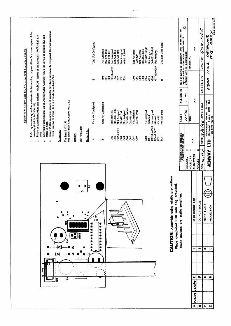
9.3 Detector PCB Schematic 630 5069.4 Detector PCB Layout 630 506
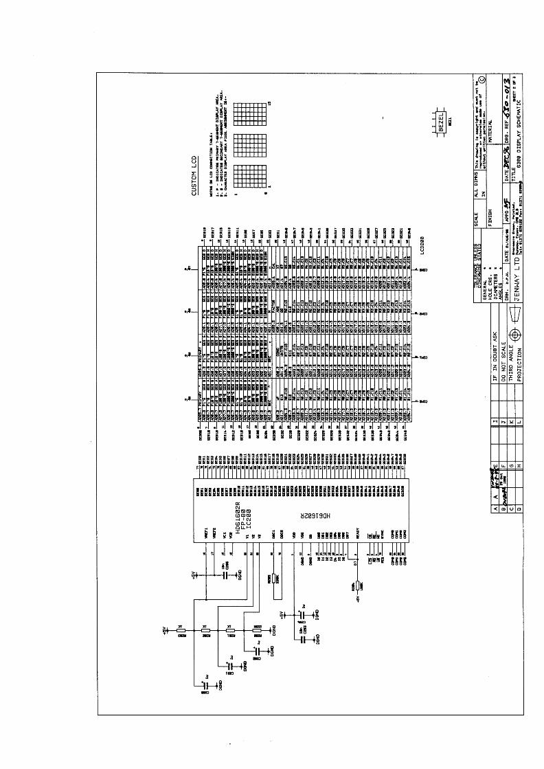
9.5 Microprocessor PCB Schematic 630 0139.6 Microprocessor PCB Layout 630 013
Jenway 6300 Ser Man 51
Section 10
Assembly Diagrams
10.1 6300 Final Assembly 630 503
10.2 6300 Lower Case Assembly 630 510
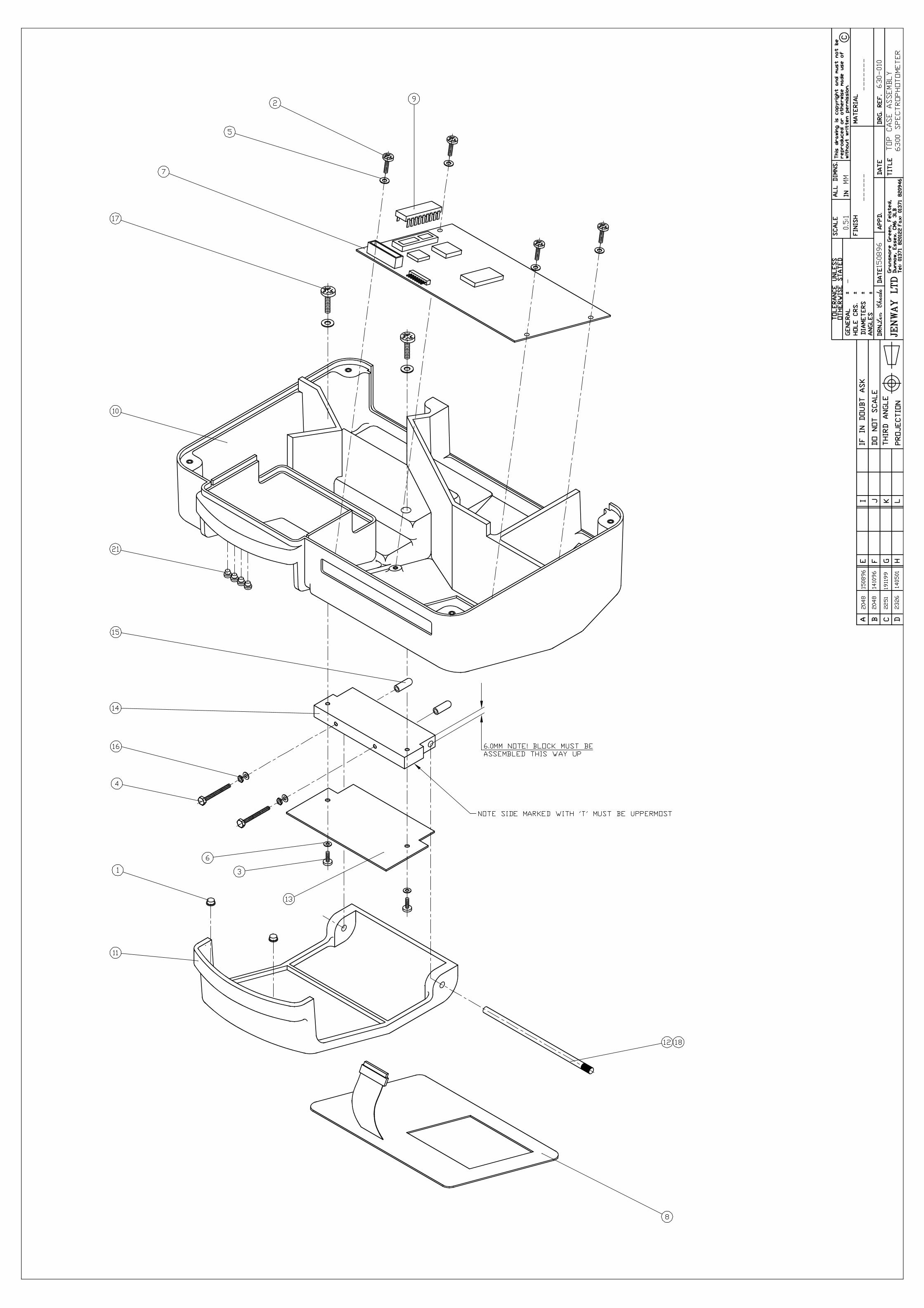
10.3 6300 Top Case Assembly 630 010
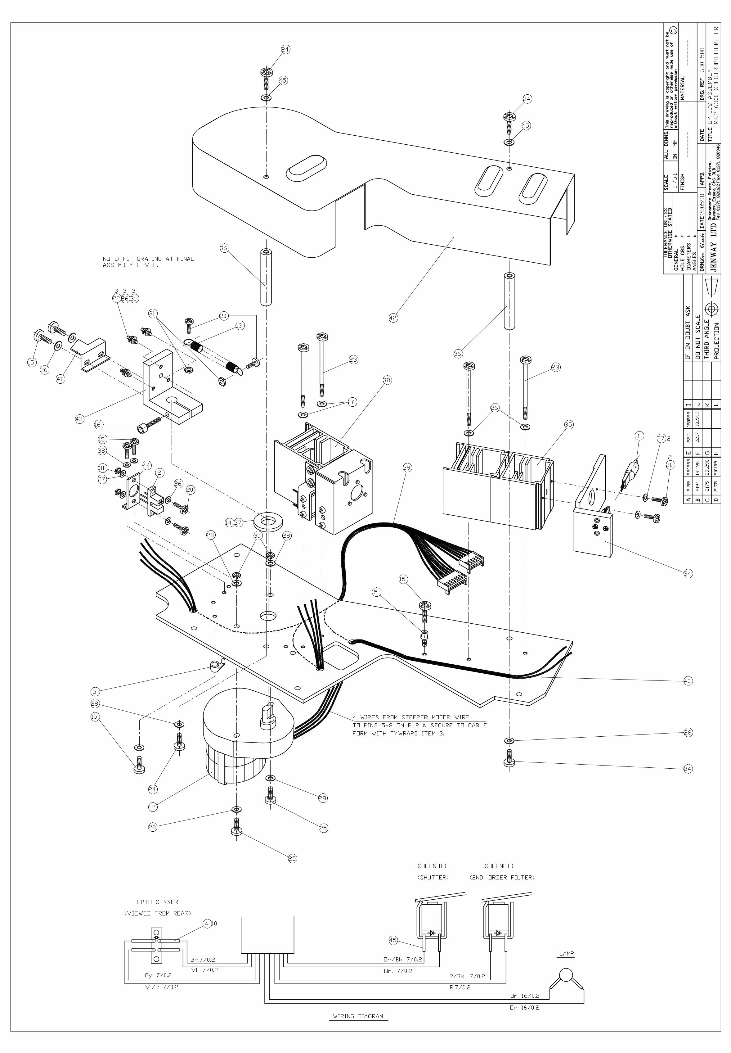
10.4 6300 Optics Assembly 630 508
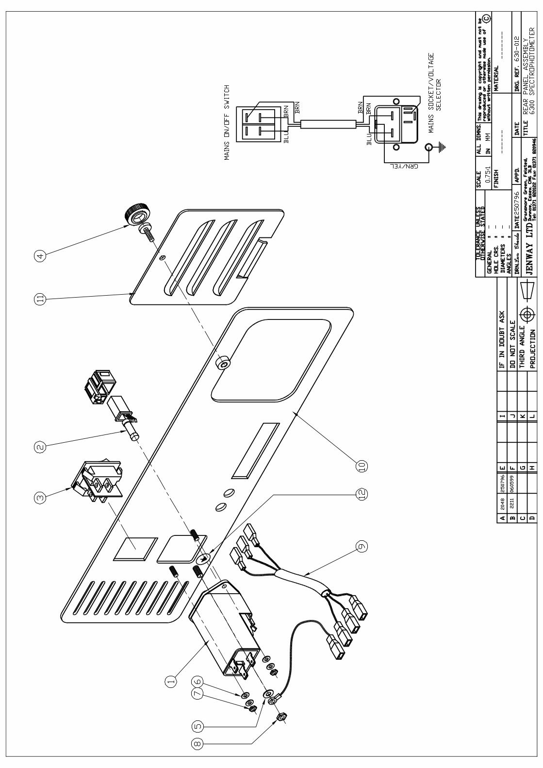
10.5 6300 Rear Panel Assembly 6630 012

Jenway 6300 Ser Man 52
Section 11
Spare Parts
11.01 Packed Instrument
11.02 Top Case Assembly
11.03 Microprocessor PCB
11.04 Lower Case Assembly
11.05 Monochromator Assembly
11.06 Detector PCB
11.07 Power Supply PCB
11.08 Rear Panel Assembly
Jenway 6300 Ser Man 53
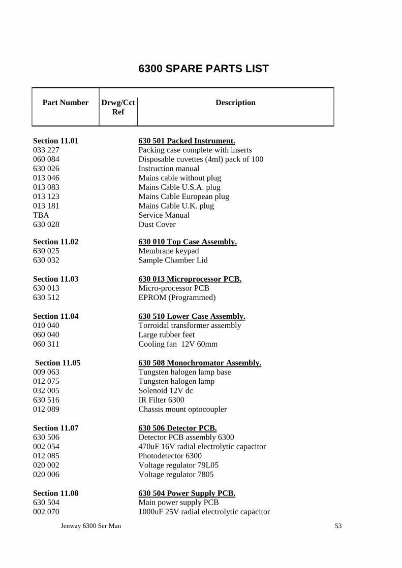
6300 SPARE PARTS LIST
Part Number Drwg/CctRef
Description
Section 11.01 630 501 Packed Instrument.033 227 Packing case complete with inserts060 084 Disposable cuvettes (4ml) pack of 100630 026 Instruction manual013 046 Mains cable without plug013 083 Mains Cable U.S.A. plug013 123 Mains Cable European plug013 181 Mains Cable U.K. plugTBA Service Manual630 028 Dust Cover
Section 11.02 630 010 Top Case Assembly.630 025 Membrane keypad630 032 Sample Chamber Lid
Section 11.03 630 013 Microprocessor PCB.630 013 Micro-processor PCB630 512 EPROM (Programmed)
Section 11.04 630 510 Lower Case Assembly.010 040 Torroidal transformer assembly060 040 Large rubber feet060 311 Cooling fan 12V 60mm
Section 11.05 630 508 Monochromator Assembly.009 063 Tungsten halogen lamp base012 075 Tungsten halogen lamp032 005 Solenoid 12V dc630 516 IR Filter 6300012 089 Chassis mount optocoupler
Section 11.07 630 506 Detector PCB.630 506 Detector PCB assembly 6300002 054 470uF 16V radial electrolytic capacitor012 085 Photodetector 6300020 002 Voltage regulator 79L05020 006 Voltage regulator 7805
Section 11.08 630 504 Power Supply PCB.630 504 Main power supply PCB002 070 1000uF 25V radial electrolytic capacitor

Jenway 6300 Ser Man 54
005 024 Bridge rectifier002 112 4700uF 40V radial electrolytic capacitor020 027 L4960 voltage regulator006 115 25 way D socket009 124 4mm socket red009 125 4mm socket black
Section 11.10 640 006 Rear Panel Assembly.009 123 Mains input socket016 021 2A fuse 20mm (for 220V supply)062 241 Lamp Panel Retaining Screw017 050 Switch rocker 2p


![Untitled-1 []3120 3120 3120 3120 3120 4160 4160 4160 4160 4760 6300 6300 6300 6300 6300 (mm) 10 13 16 20 70 13 16 20 10 13 16 20 L (mm 3725 3745 3765 3785 3805 4910 4950 6910 6930](https://static.fdocuments.in/doc/165x107/5e4dbd11312dd96173529be7/untitled-1-3120-3120-3120-3120-3120-4160-4160-4160-4160-4760-6300-6300-6300.jpg)