Jefferson Direct Vent/Natural Vent Gas...
36
INSTALLER / CONSUMER SAFETY INFORMATION 20002191 11/02 Rev. 10 PLEASE READ THIS MANUAL BEFORE INSTALLING AND USING APPLIANCE. WARNING! IF THE INFORMATION IN THIS MANUAL IS NOT FOLLOWED EXACTLY, A FIRE OR EXPLOSION MAY RESULT CAUSING PROP- ERTY DAMAGE, PERSONAL IN- JURY OR LOSS OF LIFE. FOR YOUR SAFETY Installation and service must be per- formed by a qualified installer, service agency or the gas suppler. WHAT TO DO IF YOU SMELL GAS: • Do not try to light any appliance. • Do not touch any electric switch; do not use any phone in your building. • Immediately call your gas supplier form your neighbor’s phone. Follow the gas supplier’s instructions. • If you cannot reach your gas supplier, call the fire department. DO NOT STORE OR USE GASO- LINE OR OTHER FLAMMABLE VAPORS AND LIQUIDS IN THE VICINITY OF THIS OR ANY OTHER APPLIANCE. This appliance may be installed in an after market permanently located manufac- tured (mobile) home where not prohibited by local codes. This appliance is only for use with the type of gas indicated on the rating plate. This appliance is not convertible for use with other gases unless a certified kit is used. Jefferson® Direct Vent/Natural Vent Gas Heater Homeowner’s Installation and Operation Manual Tested and listed to ANSI Z21.88b-2001 and CSA-2.33b-2001 INSTALLER: DO NOT DISCARD THIS MANUAL - LEAVE FOR HOMEOWNER CERTIFIED D E S I G N C E R T I F I E D Model JDV: 2820, 2822, 2823, 2825, 2827, 2828 410 Admiral Blvd. • Mississauga, Ontario, Canada L5T 2N6 • 905-670-7777 www.majesticproducts.com • www.vermontcastings.com Vermont Castings, Majestic Products
Transcript of Jefferson Direct Vent/Natural Vent Gas...

INSTALLER / CONSUMERSAFETY INFORMATION
20002191 11/02 Rev. 10
PLEASE READ THIS MANUALBEFORE INSTALLING AND USINGAPPLIANCE.
WARNING!IF THE INFORMATION IN THISMANUAL IS NOT FOLLOWEDEXACTLY, A FIRE OR EXPLOSIONMAY RESULT CAUSING PROP-ERTY DAMAGE, PERSONAL IN-JURY OR LOSS OF LIFE.
FOR YOUR SAFETYInstallation and service must be per-formed by a qualified installer, serviceagency or the gas suppler.
WHAT TO DO IF YOU SMELL GAS:
• Do not try to light any appliance.
• Do not touch any electric switch; donot use any phone in your building.
• Immediately call your gas supplierform your neighbor’s phone. Followthe gas supplier’s instructions.
• If you cannot reach your gas supplier,call the fire department.
DO NOT STORE OR USE GASO-LINE OR OTHER FLAMMABLEVAPORS AND LIQUIDS IN THEVICINITY OF THIS OR ANY OTHERAPPLIANCE.
This appliance may be installed in an aftermarket permanently located manufac-tured (mobile) home where not prohibitedby local codes.
This appliance is only for use with thetype of gas indicated on the rating plate.
This appliance is not convertible for usewith other gases unless a certified kit isused.
Jefferson®
Direct Vent/NaturalVent Gas Heater
Homeowner’s Installationand Operation Manual
Tested and listed toANSI Z21.88b-2001 and CSA-2.33b-2001
INSTALLER: DO NOT DISCARD THIS MANUAL - LEAVE FOR HOMEOWNER
CERTIFIED
DESIGN
CERTIFIED
Model JDV: 2820, 2822, 2823,2825, 2827, 2828
410 Admiral Blvd. • Mississauga, Ontario, Canada L5T 2N6 • 905-670-7777www.majesticproducts.com • www.vermontcastings.com
Vermont Castings, Majestic Products

22
Vermont Castings Jefferson Direct Vent/Natural Vent Gas Heater
20002191
PLEASE READ THE INSTALLATION & OPERATING INSTRUCTIONS BEFORE USING APPLIANCE.Thank you and congratulations on your purchase of a Vermont Castings stove.
IMPORTANT: Read all instructions and warnings carefully before starting installation. Failure to follow theseinstructions may result in a possible fire hazard and will void the warranty.
Table Of Contents
Installation & Operating Instructions ........................................................................................................... 3Stove Dimensions ............................................................................................................................. 4Installation Requirements .................................................................................................................. 5Locating the Stove ............................................................................................................................ 5Clearance Requirements .................................................................................................................. 5Parallel Installation ............................................................................................................................ 6Corner Installation ............................................................................................................................. 6Wall and Ceiling Clearances ............................................................................................................. 6Hearth Requirements ........................................................................................................................ 6Gas Specifications ............................................................................................................................ 7Gas Inlet and Manifold Pressures ..................................................................................................... 7High Elevations ................................................................................................................................. 7Horizontal Termination - Direct Vent ONLY ...................................................................................... 7Vertical Termination - Direct Vent ONLY .......................................................................................... 8Vent Termination Clearances - Direct Vent Only .............................................................................. 9General Venting Information - Termination Location ...................................................................... 10Termination Clearances .................................................................................................................. 11Venting Requirements - Natural Vent ONLY ................................................................................... 11Venting Requirements and Options - Direct Vent ONLY ................................................................ 12
Assembly ProceduresTools Required ................................................................................................................................ 13Unpack the Stove ............................................................................................................................ 13Install Optional Fan ......................................................................................................................... 13Venting System Assembly - Direct Vent ......................................................................................... 14Install Vent Adapter Pipe (CFM Components) ................................................................................ 14Install Vent Adapter Pipe (Simpson Dura-Vent Components) ........................................................ 15Side Wall Termination Assembly .................................................................................................... 16Vent Termination Below Grade ....................................................................................................... 17Vertical (Through the Roof) Vent Assembly .................................................................................... 18Venting System Assembly - Natural Vent ....................................................................................... 19Install the Vent Pipe ........................................................................................................................ 19Install the Log Set ........................................................................................................................... 20Connect Gas Supply Line ............................................................................................................... 21Burner Information .......................................................................................................................... 21Air Shutter Adjustment .................................................................................................................... 21Complete the Assembly .................................................................................................................. 23Install ON/OFF Switch ..................................................................................................................... 23Install the Stove Front ..................................................................................................................... 23Thermostat Connection (Optional) .................................................................................................. 24
OperationYour First Fire .................................................................................................................................. 25Pilot and Burner Inspection ............................................................................................................. 25Flame & Temperature Adjustment .................................................................................................. 25Flame Characteristics ...................................................................................................................... 25Lighting and Operating Instructions ................................................................................................ 26Troubleshooting - Honeywell #8420 Gas Control System .............................................................. 27Fuel Conversion Instructions ........................................................................................................... 28
MaintenanceAnnual System Inspection ............................................................................................................... 30Logset and Burner/Cleaning and Inspection ................................................................................... 30Care of Cast Iron ............................................................................................................................. 30Cleaning the Glass .......................................................................................................................... 30Glass Replacement ......................................................................................................................... 30Gasket Replacement ....................................................................................................................... 31Inspect the Vent System Annually .................................................................................................. 31Check the Gas Flame Regularly ..................................................................................................... 31Stove Dissasembly .......................................................................................................................... 31Wiring Diagrams .............................................................................................................................. 32Replacement Parts .......................................................................................................................... 33
Optional Accessories ................................................................................................................................... 35Warranty ........................................................................................................................................................ 36

3
Vermont Castings Jefferson Direct Vent/Natural Vent Gas Heater
20002191
The Jefferson Direct Vent/Natural Vent Room Heater,Model Nos. 2820, 2822, 2823, 2825, 2827 and 2828, is avented gas appliance listed to the ANSI Standard Z21.88b-2001 and CSA-2.33b-2001 for Vented Room Heaters, andCSA 2.17-M91, Gas-Fired Appliances For Use at High Alti-tudes.
The installation of the Jefferson Direct Vent/Natural VentRoom Heater must conform with local codes, or in the ab-sence of local codes, with National Fuel Gas Code, ANSIZ223.1 — latest edition and CSA B-149.1 Installation Code.(EXCEPTION: Do not derate this appliance for altitude.Maintain the manifold pressure at 3.5 inches w.c. for Natu-ral Gas and 10 inches w.c. for LP gas at maximum input.)
This appliance is only for use with the type of gas indi-cated on the rating plate. This appliance is not convertiblefor use with other gases unless a certified kit is used.
Installation and replacement of gas piping, gasutilization equipment or accessories, and repair andservicing of equipment shall be performed only by aqualified agency. The term “qualified agency” meansany individual, firm, corporation, or company that eitherin person or through a representative is engaged inand is responsible for (a) installation or replacement ofgas piping, or (b), the connection, installation, repair,or servicing of equipment, who is experienced in suchwork, familiar with all precautions required, and hascomplied with all the requirements of the authorityhaving jurisdiction.
The Jefferson Direct Vent/Natural Vent Room Heatershould be inspected before use and at least annuallyby a qualified service agency. It is imperative thatcontrol compartments, burners, and circulating airpassageways of the appliance be kept clean.
The Jefferson Direct Vent/Natural Vent Room Heaterand its individual shut-off valve must be disconnected fromthe gas supply piping during any pressure testing of thatsystem at test pressures in excess of 1/2 psig (3.5 kPa).
The Jefferson Direct Vent/Natural Vent Room Heatermust be isolated from the gas supply piping system by clos-ing its individual manual shutoff valve during any pressuretesting of the gas supply piping system at test pressuresequal to or less than 1/2 psig.
'Direct Vent' describes a sealed combustion system inwhich incoming outside air for combustion and outgoingexhaust enter and exit through two separate concentricpassages within the same sealed vent system. The sys-tem does not use room air to support combustion. TheDirect Vent system permits the gas appliance to be venteddirectly to the outside atmosphere through the side of thehouse or vertically through the roof. Conventional ventingsystems (Natural Vent) take air from the room for combus-tion and vent the exhaust vertically through the roof to theatmosphere.
This appliance is approved for bedroom installations inthe U.S. and Canada.
This appliance may be installed in an aftermarket*manufactured (mobile) home, where not prohibited bystate or local codes.
WARNING: Operation of this heater when not con-nected to a properly installed and maintained ventingsystem can result in carbon monoxide (CO) poisoningand possible death.
The Jefferson Direct Vent/Natural Vent Room Heater,when installed, must be electrically grounded in accordancewith local codes or, in the absence of local codes, with theNational Electrical Code ANSI/NFPA 70, (latest edition), orof the current Canadian Electrical Code C22.1.
Due to high temperatures this appliance should belocated out of traffic and away from furniture anddraperies.
WARNING: This appliance is hot while in operation.Keep children, clothing, and furniture away. Contactmay cause burns or ignition of combustible materials.
Children and adults should be alerted to the hazardsof high surface temperatures and should stay away toavoid burns or clothing ignition. Young children shouldbe carefully supervised when they are in the sameroom as the appliance.
Clothing or other flammable materials should not beplaced on or near the appliance.
Any safety screen, glass or guard removed forservicing an appliance must be replaced prior tooperating the appliance.
The appliance area must be kept clear and free fromcombustible materials, gasoline, and other flammablevapors and liquids.
The flow of combustion and ventilation air must notbe obstructed. The installation must include adequateaccessibility and clearance for servicing and properoperation.
WARNING: Do not operate the Room Heater with theglass panel removed, cracked or broken. Replacementof the panel should be done by a licensed or qualifiedservice person.
Do not use this appliance if any part has been underwater. Immediately call a qualified service technicianto inspect the appliance and to replace any part of thecontrol system and any gas control which has beenunder water.
Do not burn wood, trash or any other material forwhich this appliance was not designed. This applianceis designed to burn either natural gas or propane only.
This gas appliance must not be connected to a chimneyflue serving a separate solid-fuel burning appliance.
CAUTION: Label all wires prior to disconnectionwhen servicing controls. Wiring errors can causeimproper and dangerous operation.
Verify proper operation after servicing.Proposition 65 Warning: Fuels used in gas,
woodburning or oil fired appliances, and the products ofcombustion of such fuels, contain chemicals known to theState of California to cause cancer, birth defects and otherreproductive harm.
California Health & Safety Code Sec. 25249.6
* Aftermarket: Completion of sale, nor for purpose of resale,from the manufacturer.
Installation & Operating Instructions

44
Vermont Castings Jefferson Direct Vent/Natural Vent Gas Heater
20002191
Jefferson Direct Vent/ Natural Vent Stove Dimensions
Attention
The Jefferson stove is shipped from the factory as a Direct Vent Gas Heater. This heater may be convertedinto a Natural Vent unit in the field. If a Natural Vent heater is desired, the Vermont Castings Z31D00FSDHAG Draft Hood must be directly installed to the top of the unit according to the installationinstructions. The Draft Hood Adapter is available in the 7FSKHASK stove kit or as a separate item.
When the Jefferson stove is converted to Natural Vent, it uses 4” vent pipe. For aesthetic purposes the CFMdirect vent system may be used up to the ceiling.
See Page 6 for Flue CollarCenterline Dimensions.
ST206
Fig. 1 Jefferson dimensions.
28¹⁄₂"
24"
3"
14¹⁄₂"
CL
8"
Valve Inlet

5
Vermont Castings Jefferson Direct Vent/Natural Vent Gas Heater
20002191
Installation Requirements
The installation must conform with local codes or, in theabsence of local codes, with the National Fuel GasCode, ANSI Z223.1 - latest edition. (EXCEPTION: Donot derate this appliance for altitude. Maintain themanifold pressure at 3.5 inches w.c. for Natural Gas,and 10 inches w.c. for Propane).
In Canada, installation must be in accordance with thecurrent CSA B-149.1 Installation Codes and/or localcodes.
The installation should be done by a qualified ser-vice person who is familiar with the building codesand installation techniques appropriate for your areato accomplish a safe and effective installation.
Your dealer or your local gas supplier will be able torefer a qualified service person.
WARNING: Due to high temperatures, the HEATERshould be located out of traffic and away from furnitureand draperies.
The surface of the Heater Is hot when it is in use.Young children should be watched carefully whenthey are in the same room when the Heater is in use,and they should be taught to avoid the hot surface.Keep any objects that can burn well away from theHeater, and observe the recommended clearancesthat follow.
Locating the Stove
In choosing a location for the stove, consider:
• The location of outside walls;
• Where additional heat is needed:
• Where family members gather most often;
• The vent system requirements.
NOTE: We do not recommend the use of wallpaper nextto this stove. Over time, radiant heat may cause thewallpaper to shrink, or may adversely affect the bindersin the wallpaper adhesive.
Clearance Requirements
Minimum Clearances to Combustible Materials
Measure side clearances as shown in Figures 3 and 4from the outer edge of the cast iron stove top. Measurerear clearances from the outermost surface of the steelrear skirt.
The Jefferson heater is approved for installation into analcove constructed of combustible materials to thedimensions and clearances shown on the next page.
The same clearances apply in a standard parallel instal-lation.
AB
E
C
D
ST207
A. Flat on corner wallB. Room DividerC. Island
D. Cross CornerE. Flat on wall
Fig. 2 Possible stove locations.
Direct Vent System Only
WARNING:• Always maintain required
clearances (air spaces) to nearby combustiblesto prevent fire hazard. Do not fill air spaces withinsulation. All venting components mustmaintain a 1" (25mm) clearance to combustiblematerials. Maintain a 6” (150mm) clearancewhen using single wall pipe.
• The gas appliance and vent system must bevented directly to the outside of the building andnever be attached to a chimney serving aseparate solid fuel or gas-burning appliance.
• Refer to the manufacturer's instructionsincluded with the venting system for completeinstallation procedures.

66
Vermont Castings Jefferson Direct Vent/Natural Vent Gas Heater
20002191
Parallel Installation:Minimum Clearance and Flue Centerline,
Direct Vent and Natural Vent
CL
CL
B
D
C
A
Stove Clearances A: 4” (102mm)B: 4” (102mm)
Pipe Centerlines C: 14¹⁄₂” (369mm)D: 9” (229mm) ST128a
Fig. 3 Parallel installation, minimum back and side clearances,and flue centerlines.
Hearth Requirements
The Jefferson Heater must be installed on rigid flooring.When the heater is installed directly on any combustiblesurface other than wood flooring, a metal or wood panelextending the full width and depth of the unit must beused as the hearth. There are no other hearth require-ments.
A
Wall Thimble Centerline from Floor
AEffective MinimumWall Thimble 58 ¹/₄” (1480mm)(CFM Majestic Pipe)Centerline 54¹⁄₄” (1378mm) (Simpson DuraVent Pipe)
ST131a
Fig. 5 Minimum wall thimble centerline.
Direct Vent Only
Wall and Ceiling Clearances
* needed for installing DuraVent Minimum Vent Kit #2792 orCFM/Majestic Minimum Vent Kit #7TFSDVSK.
A
C
D
B
A: Rear Wall 4” (102mm)B: Min. Clearance 43¹⁄₂” (1105mm)*C: Min. Alcove Height 72” (1830mm)*D: Max. Alcove Depth 48” (1220mm) Sidewall Clearance 4” (102mm)
ST101a
Fig. 6 Dimensions and clearances to ceiling or alcove.
Direct Vent OnlyCorner Installation: Minimum Clearance andFlue Centerline, Direct Vent & Natural Vent
Stove Clearance A: 4” (102mm)Pipe Centerline B: 14³⁄₄” (375mm)
ST129b
Fig. 4 Corner installation, minimum corner clearances and fluecenterline.
A
A
B
B

7
Vermont Castings Jefferson Direct Vent/Natural Vent Gas Heater
20002191
Weight: Fully assembled; 350 lbs.
Jefferson Direct Vent/Natural VentCertified to:
ANSI Z21.88b-2001 / CSA 2.33b-2001Vented Gas Fireplace Heaters
The installation of your Vermont Castings stove mustconform with local codes, or in the absence of localcodes, with the National Fuel Gas Code ANSIZ223.1 - latest edition, or CSA B149.1 Installationcode. (EXCEPTION: Do not derate this appliance foraltitude up to 4,500 feet (1,370m). Maintain themanifold pressure at 3.5” w.c. for Natural Gas and10.0” w.c. for LP Gas.
High Elevations
Input ratings are shown in BTU per hour and arecertified without deration for elevations up to4,500 feet (1,370m) above sea level.
For elevations above 4,500 feet (1,370m) in USA,installations must be in accordance with thecurrent ANSI Z223.1 and/or local codes havingjurisdiction.
In Canada, please consult provincial and/or localauthorities having jurisdiction for installations atelevations above 4,500 feet (1,370m).
WARNING: Improper installation, adjust-ment, alteration, service or maintenance cancause injury or property damage. Refer tothis manual for correct installation andoperational procedures. For assistance oradditional information consult a qualifiedinstaller, service agency, or the gas supplier.
Gas Specifications
Max. Min.Input Input
Model Fuel Gas Control BTU/h BTU/hJDVRN Nat Millivolt 28,000 20,000
JDVRP Prop Millivolt 28,000 19,000
Natural LP (Propane)Inlet Minimum 5.5” w.c. 11.0” w.c.
Inlet Maximum 14.0” w.c. 14.0” w.c.
Manifold Pressure 3.5” w.c. 10.0” w.c.
Gas Inlet and Manifold Pressures
Horizontal Termination -Direct Vent ONLY
The vent must rise vertically a minimum of 24” (610mm)off the top of the unit, before the first elbow. The horizon-tal run may extend up to 20’ (6m) and include a verticalrise of up to 40’ (12m). (Fig. 7) Horizontal terminationmust also meet the criteria shown in Figures 10 through 12.
• Approved vent systems must terminate above andincluding the heavy line in Figure 7.
• Two 45˚ elbows may be substituted for each single90˚ elbow.
• With a rise between 2' - 6', one 90˚ or two 45˚ elbowsmay be used.
ST134a
Fig. 7 Horizontal vent termination window.
20
19
18
16
15
14
13
12
11
10
9
8
7
6
5
4
3
2
1
0
1 2 3 4 5 6 7 8 9 10 11 12 13 14 15 16 17 18 19 20
Ver
tica
l Ru
n (
in f
eet)
(Mea
sure
d f
rom
th
e ap
plia
nce
flu
e co
llar
to t
he
top
of
the
ven
t p
ipe.
)
Horizontal Run (in feet)
21
22
2324
25
26
27
28
29
30
31
32
33
34
35
36
37
38
39
40
May use up tothree 90° Elbows
One 90°Elbow
UnacceptableVenting Configuration

88
Vermont Castings Jefferson Direct Vent/Natural Vent Gas Heater
20002191
Vertical Termination - Direct Vent ONLY
A vertical vent system must terminate no less than 8'(2.44m) and no more than 40’ (12m) above the appli-ance flue collar. A 2¹⁄₄" restrictor plate (supplied) must beused, where specified, in all vertically terminated ventsystems. (Refer to Figure 8) NOTE: The restrictor platesupplied with the vertical termination should bediscarded. Install restrictor plate supplied with thestove directly at stove outlet. A vertically terminatedvent system must also conform to the following criteria:• No more than two 90˚ elbows may be used.• Two 45˚ elbows may be substituted for one 90˚ elbow.
No more than six elbows may be used.• Vent must rise a minimum of 2 feet before offset is used.• Termination height must conform to roof clearance as
specified in Figure 9.
*The Restictor Plate is used on Direct Ventinstallations only.
20
19
18
16
15
14
13
12
11
10
9
8
7
6
5
4
3
2
1
0
201 2 3 4 5 6 7 8 9 10 11 12 13 14 15 16 17 18 19
Ver
tica
l Ru
n (
in f
eet)
(Mea
sure
from
the
appl
ianc
e flu
e co
llar
to th
e to
p of
the
vent
pip
e.)
Horizontal Run (in feet)
21
22
2324
25
26
27
28
29
30
31
32
33
34
35
36
37
38
39
40
ST132a
Fig. 8 Vertical vent termination window.
ALL VERTICALTERMINATIONSREQUIRE USEOF THE 2¹⁄₄”RESTRICTORPLATE*
Vertical terminationsmust be within this area
UnacceptableVenting Configuration
No Restr
ictor P
late
Vent Termination Clearances
When planning the installation, consider the location ofthe vent terminal and clearances. Some of the mostcommon clearances to keep in mind are shown in Figure10.
Important: All vent clearances must be maintained.Check your vent termination clearances againstFigures 10 and 11.
The vent should be placed so that people cannot beburned by accidentally touching the vent surfaces whenthe stove is operating.
The vent termination should be located where it cannotbe damaged by such things as automobile doors, lawnmowers or snowblowers and it should be located awayfrom areas where it could become blocked by snow, etc.
Some considerations are:
• Obstructions or impediments to venting.
• Nearby combustible materials that could come intocontact with combustion exhaust gases.
• Other nearby openings {within 9" (230mm)} throughwhich exhaust gas could reenter the building.
• All vegetation within 3' (.9m) that may interfere withthe draft.
Other factors that influence where the installation will besited include the location of outside walls, where addi-tional heat may be desired in the home, where the familymembers gather most regularly, and perhaps mostimportantly, the distance limitations of the ventingsystem.
IMPORTANTDirect Vent Only
• The horizontal termination must not be recessedinto the exterior wall or siding.
• Horizontal vent runs must be level toward the venttermination.
• Clearances around the vent termination must bemaintained.
• For installations using Simpson DuraVent pipe,parallel installations with minimum wall clearancehave restricted access for connecting the Horizon-tal Vent Cap straps to the vent pipe. See themaker’s instructions for recommended installationprocedures.

9
Vermont Castings Jefferson Direct Vent/Natural Vent Gas Heater
20002191
Vent Termination Clearances - Direct Vent ONLY
Your stove is approved to be vented either through theside wall, or vertical through the roof.• Vermont Castings, Majestic Products does not
require any opening for inspection of vent pipe.• Only Vermont Castings, Majestic Products and
Simpson DuraVent venting components specifi-cally approved and labelled for this stove may beused.
• Minimum clearances between vent pipes andcombustible materials is one (1") inch (25 mm),except where stated otherwise.
• Venting terminals shall not be recessed into a wall orsiding.
• Horizontal venting must be installed on a level planewithout an inclining or declining slope.
There must not be any obstruction such as bushes,garden sheds, fences, decks or utility buildings within24" from the front of the termination hood.Do not locate termination hood where excessive snowor ice build up may occur. Be sure to check vent termi-nation area after snow falls, and clear to preventaccidental blockage of venting system. When usingsnow blowers, make sure snow is not directed towardsvent termination area.
Location of Vent Termination
It is imperative the vent termination be located observ-ing the minimum clearances as shown in Figure 9.

1010
Vermont Castings Jefferson Direct Vent/Natural Vent Gas Heater
20002191
V
V
V
V
V
V
V
X
X
X
D
E
B
B B
C
BM
B
A
JK
F
L
VENT TERMINATION AIR SUPPLY INLET AREA WHERE TERMINAL IS NOT PERMITTED
H
I
FixedClosedFixed
Closed
OperableOperable Fixed
Closed
VB
INSIDECORNER DETAIL
V
A
G
V
NN
V
V
G
G
A
CFM145a
Fig. 9 Vent termination clearances.
A = Clearance above grade, veranda, porch, 12 inches (30cm) 12 inches (30cm)deck, or balcony
B = Clearance to window or door that may be 6 in (15cm) for appliances 6 in (15cm) for appliancesopened < 10,000Btuh (3kW), 12 in (30cm) < 10,000 Btuh (3kW), 9 in
for appliances > 10,000 Btuh (3kW) and (23cm) for appliances > 10,000< 100,000 Btuh (30kW), 36 inches (91cm) Btuh (3kW) and < 50,000 Btuhfor appliances > 100,000 Btuh (30kW) (15kW), 12 in (30cm) for
appliances > 50,000 Btuh (15kW)C = Clearance to permanently closed window 12” (305mm) recommended to 12” (305mm) recommended to
prevent window condensation prevent window condensationD = Vertical clearance to ventilated soffit located
above the terminal within a horizontal 18” (458mm) 18” (458mm)distance of 2 feet (610mm) from the centerline of the terminal
E = Clearance to unventilated soffit 12” (305mm) 12” (305mm)F = Clearance to outside corner see next page see next pageG = Clearance to inside corner (see next page) see next page see next pageH = Clearance to each inside of center line 3 feet (91cm) within a height of 15 feet 3 ft (91cm) within a height of 15 ft
extended above meter/regulator assembly above the meter/regulator assembly above the meter/regulator assyI = Clearance to service regulator vent outlet 3 feet (91cm) 3 feet (91cm)J = Clearance to nonmechanical air supply inlet 6 inches (15cm) for appliances < 10,000 6 inches (15cm) for appliances
to building or the combustion air inlet to any Btuh (3kW), 12 inches (30cm) for < 10,000 Btuh (3kW), 9 inchesother appliances appliances > 10,000 Btuh (3kW) and < (23cm) for appliances > 10,000
100,000 Btuh (30kW), 36 inches (91cm) Btuh (3kW) and < 50,000 Btuhfor appliances > 100,000 Btuh (30kW) (15kW), 12 inches (30cm) for
appliances > 50,000 Btuh (15kW)K = Clearance to a mechanical air supply inlet 6 feet (1.83m) 3 feet (91cm) above if within 10
feet (3m) horizontallyL = Clearance above paved sidewalk or paved 7 feet (2.13m)† 7 feet (2.13m)†
driveway located on public propertyM = Clearance under veranda, porch, deck or 12 inches (30cm)c 12 inches (30cm)†
balconyN = Clearance above a roof shall extend a minimum of 24” (610mm) above the highest point when it passes through the roof
surface, and any other obstruction within a horizontal distance of 18” (450mm).1 In accordance with the current CSA-B149 Installation Codes2 In accordance with the current ANSI Z223.1/NFPA 54 National Fuel Gas Codes† A vent shall not terminate directly above a sidewalk or paved driveway which is located between two single family dwellings and servesboth dwellings‡ only permitted if veranda, porch, deck or balcony is fully open on a minimum 2 sides beneath the floor:NOTE: 1. Local codes or regulations may require different clearances.
2. The special venting system used on Vermont Castings Direct Vent Stoves are certified as part of the appliance, with clearancestested and approved by the listing agency.
Canadian Installations1 US Installations2
General Venting Information - Termination Location
11
Vermont Castings Jefferson Direct Vent/Natural Vent Gas Heater
20002191
Venting Requirements - Natural Vent Only
Venting Runs
Horizontal Run (in feet)
Ver
tica
l Ru
n (
in f
eet)
(Mea
sure
d fr
om fl
oor
of u
nit t
oto
p of
ven
t cap
.) A: Vertical installations up to 36 feet (12m) in height. Up to an 18 ft. horizontal vent run can be installed within the vent system using a maximum of two 90-degree elbows or four 45-degree elbows.
B: Vertical installations up to 36 feet (12m) in height. Up to a 24 ft. horizontal vent run can be installed within the vent system using a maximum of two 45-degree elbows. (Ratio = 2/3, Hor./Vert.)
= Acceptable venting configuration
= Unacceptable venting configuration
36
34
32
30
28
26
24
22
20
18
16
14
12
10
8
16 18 20 22 24 26 28 30 32 34 36 4 6 8 10 12 14
AB
Fig. 11 Vent termination window - Natural Vent ONLY.
FP567b
NOTE: When using the FSDHAG, the restrictor platesupplied with the stove is not used.
Outside CornerInside Corner
Termination ClearancesTermination clearances for buildings with combustible and noncombustible exteriors.
A =Combustible 6"(152mm)Noncombustible 2"(50mm)
B =Combustible 6"(152mm)Noncombustible 2"(50mm)
A
Balcony - with no side wall
G = Combustible&Noncombustible 12"(305mm)
G
Balcony - with perpendicular side wall
H = 24"(610mm)
J = 20"(508mm)
H
J
B
Recessed Location
C = Maximum depth of 48" (1219mm) for recessed location. D = Minimum width for back wall of a recessed location. Combustible 38"(965mm) Noncombustible 24"(610mm)
E = Clearance from corner in recessed location. Combustible 6"(152mm) Noncombustible 2"(50mm)
CD
CE
V
V
Combustible &Noncombustible
V V
V
584-14
Fig. 10 Termination clearances.

1212
Vermont Castings Jefferson Direct Vent/Natural Vent Gas Heater
20002191
Venting Requirements and Options -Direct Vent ONLY
Approved Vent System ComponentsThe Stardance Heater must be vented to the outdoorsthrough an adjacent exterior wall or through the roof.The venting system must be comprised of the appropri-ate listed venting components specified on this page.These parts are available from DuraVent Corporation oryour Vermont Castings Majestic Products Dealer.
See Figure 4 for dimensions relevant to the standardminimum-vent kits.
Simpson DuraVent ComponentsMinimum Horizontal Vent Kit 2792Starter Pipe Assembly (incl. inner & outer sections)2768*90° Elbow, Blk. 990B*45° Elbow, Gal. 9456” Straight, Blk. 908B*9” Straight, Blk. 907B11” - 14⁵⁄₈” Adjustable Straight Section 911B12” Straight 90624” Straight 904B*36” Straight 903B48” Straight 902Horizontal Vent Cap 984*Wall Plate* 940Vinyl Siding Shield 950Snorkel Termination - 14” 982Snorkel Termination - 36” 981Wall Strap 988Cathedral Ceiling Support Box 941Storm Collar 953Firestop Spacer 963Flashing 0/12 - 6/12 943Flashing 6/12 - 12/12 943SVertical Termination Cap 991*Included in Minimum Horizontal Vent Kit #2792
All DuraVent Straight vent pipe sections have a netlength 1¹⁄₂” (37mm) less than the nominal dimension;i.e., a 6” (152mm) Straight pipe section has aneffective length of 4¹⁄₂” (115mm).
CFM Vent ComponentsThe following kits are available to meet the needs ofmost installations. All pipe has a 7" outer diameter andincludes a 4" diameter inner section. A (CG) designa-tion indicates the part is finished in Charcoal Graypaint. Consult your dealer about other vent parts thatmay be appropriate to complete the installation.Min. Through the Wall Vent Kit 7TFSMSK(1) 90-Degree Elbow (CG)(1) 24" Straight pipe (CG)(1) 36" Straight pipe (CG)(1) Side Wall Termination(1) Firestop(1) Zero-clearance sleeve(1) Hardware package
(1) Finishing plate (CG)(1) Finishing collar (CG)(4) Polished Brass flue pipe ringsThrough the Wall Vent Kit 7TFSDVSK(1) 90-Degree Elbow (CG)(1) 24" Straight pipe (CG)(1) 48" Straight pipe (CG)(1) Side Wall Termination(1) Firestop(1) Zero-clearance sleeve(1) Hardware package(1) Finishing plate (CG)(1) Finishing collar (CG)(4) Polished Brass flue pipe ringsThrough the Wall Vent Kit forBelow-Grade Termination 7TFSDVSKSIncludes all of the above parts plus(1) Snorkel TerminationVertical Termination Kit, 1/12-6/12 Pitch 7TDVSKVA(1) Combination Horizontal Offset / Roof Support(1) Vertical Termination(1) Storm Collar(1) 1/12-6/12 Flashing(1) Finishing Plate (CG)(1) Finishing Collar (CG)(1) Polished Brass Flue Pipe Ring(1) Hardware PackageVertical Termination Kit, 7/12-12/12 Pitch 7TDVSKVB(1) 7/12 - 12/12 Flashingand all of the other Vertical Termination parts.Vertical Termination, Flat Roof 7DVSKVF(1) Flat Flashingand all of the other Vertical Termination parts.Twist Lock 24" Straight Pipe (CG) 7TFSDVP24(1) 24" Non-adjustable Pipe(1) Polished Brass Flue Pipe RingTwist Lock 48" Straight Pipe (CG) 7TFSDVP48(1) 48" Nonadjustable Pipe(1) Polished Brass Flue Pipe RingTwist Lock 45-Degree Elbow (CG) 7TFSDVT45for vertical offsets(1) 45-degree Elbow(1) Polished Brass Flue Pipe RingDraft Hood Adapter FSDHAGNV Stove Kit 7FSSK(1) 7” Diameter Polished Brass Trim Ring(1) 48” Nonadjustable Pipe (CG)(1) 24” Nonadjustable Pipe (CG)(1) Finishing Plate(1) Finishing Collar (CG)(1) 90 Degree Elbow (CG)Stove Kit 7FSDHASKIncludes all parts in the 7FSSK plus the Draft Hood AdapterFSDHAGCombination Offset/Roof Support 7DVCSAttic Insulation Shield 7DVAIS7" Charcoal Gray Pipe Rings, (4) 7FSDRG7" Polished Brass Pipe Rings (4) 7FSDRPWall Thimble 942GNOTE: Direct vent pipe may be used on the NaturalVent system from the top of the draft hood adapter tothe ceiling.

13
Vermont Castings Jefferson Direct Vent/Natural Vent Gas Heater
20002191
Assembly Procedures
Failure to position the parts inaccordance with these diagrams orfailure to use only parts specifically
approved for use with this heater may result inproperty damage or personal injury.
This heater and components are heavy. Havehelp available for assembly.
WARNING
Tools Required
• Phillips screwdriver (stub) • power drill• utility knife • reciprocating saw• metal drill bit: size 28 (.140”/3.5mm)
Unpack the StoveThe parts bag containing this manual also includes thefollowing parts:
• Remote Switch • Switch Bracket• Switch Wire • Three 1/4-20 x 3/8” screws• Cement • Restrictor Plate• (2) #10 sheet metal screws
The Logset and 4” Inner Vent Starter Pipe are packedinside the firebox. Use the following procedure tounpack these parts.
1. Lift the Stove Front up and then swing the bottomout and away to disengage it from the stove body.Refer to Figure 37, Page 22.
2. Swing open the swiveling latches at the top left andright corners of the glass frame. (Fig. 12)
ST208
Fig. 12 Swivel the latches to release the glass frame fromthe firebox.
3. Pull the top edge of the glass and frame assemblyaway from the firebox, and lift it off its supports onthe bottom of the firebox face. Place the assemblyout of the way on a flat, padded surface such as acounter protected by a towel.
4. Take the logset and all other loose parts out of thefirebox, and set them aside in a protected area forinstallation after the venting is complete.
NOTE: Verify the two relief doors (located on top ofthe firebox) are properly seated on the gasket. Thedoors should sit flush on the gasket, and should lifteasily from the seal around the opening.
Install the Optional Fan
If you are installing the optional convection Fan Kit#2960 (FK28), continue here. If you will not install aFan Kit, go to page 14, Venting System Assembly.
1. The fan kit includes a Blower Assembly and aRheostat Assembly, connected by a cable. (Fig. 14)The Blower Assembly and the Rheostat mount to therear shroud of the stove. The assembly includes a‘snapstat’ which automatically turns the fan ON (orOFF) above (or below) approximately 109°F (43°C).The Rheostat also provides a range of fan speedsettings from Off (which overrides the snapstatfunction ) to HIGH. Unpack and inspect the Blowerassembly. Confirm that the fan spins freely.
2. Attach the snapstat assembly to the snapstat bracketwith two sheet metal screws. (Fig. 18) Remove the1/4-20 x 3/8” hex head bolt installed in the hole in theright rear ledge of the firebox. Use that bolt to securethe snapstat bracket to the firebox. The mounting holeis slotted to let you adjust the bracket so that thesnapstat bracket head makes contact with the firebox.(Fig. 13)
1/4-20 x 3/8”PhillipsScrew
1/2” SheetMetal Screw
SnapstatSnapstat Bracket
ST239
Fig. 13 Snapstat assembly and installation.

1414
Vermont Castings Jefferson Direct Vent/Natural Vent Gas Heater
20002191
General Information
The Jefferson is approved for installation only with thevent components listed on Page 12. Follow the ventcomponent instructions exactly.
For U.S. installations: The venting system mustconform with local codes and/or the current NationalFuel Gas Code, ANSI Z223.1
For Canadian installations: The venting system mustconform to the current CSA B149.1 installation code.
Install the Vent Adapter Pipe
(CFM Vent Components)
1. Install the Restrictor Plate. Consult the ‘Vent RunSpecifications’ on page 8 to determine whether therestrictor plate is needed. If so, put the restrictorplate in place within the inner flue collar as shown inFigure 16. NOTE: The restrictor plate supplied withthe vertical termination should be discarded. Installrestrictor plate supplied with the stove directly atstove outlet.
Venting System Assembly - Direct Vent
2. Attach Inner Starter Pipe, (found in with thelogset), to the next section of inner pipe.• Run a bead of sealant about 1/2” from the upperend of the Inner starter pipe and join the two sec-tions together.• Drill three pilot holes into the Inner Starter andsecure the assembly with three sheet metal screws.(Fig. 17)
3. Dry fit the Inner pipe assembly to the stove anddetermine the required vent length.• Insert the vent assembly into the flue collar, but donot attach. Measure to determine the correct lengthrequired for your installation and cut the upper endof the pipe as necessary.• Dry fit the outer vent section and cut to match theheight of the Inner assembly.
ST210
Fig. 16 Install the restrictor plate only if required for theventing configuration. Refer to page 8.
UpperFlange
ST240
Fig. 19 The upper flange of the fan skirt should be locatedbehind the lower edge of the shroud.
toControlValve
ST241
Fig. 20 Correct position of fan skirt installation.
3. Attach the fan to the rear shroud by engaging theupper flange of the fan skirt under the lower edge ofthe shroud and secure the skirt with the four screwsand one star washer provided. (Fig. 14)
4. The rheostat control switch attaches to the left side ofthe valve bracket at the front of the stove.
• Remove the plug from the rheostat bracket.• Insert the switch box shaft through the hole in theback of the right side of the valve bracket, aligningthe locator pin with the smaller hole in that bracket.• Attach the retaining nut to the switch control shaftto secure it to the plate.• Attach the Control Knob to the rheostat shaft.• Use the wire tie to secure the fan and rheostatwire harnesses together.

15
Vermont Castings Jefferson Direct Vent/Natural Vent Gas Heater
20002191
• Side Wall Terminations: Dry fit the inner elbowwith the vertical inner vent and confirm the centerlinealignment with the wall thimble opening.
4. Attach the Inner Vent Assembly to the stove.
• Run a bead of sealant around the bottom end ofthe starter pipe and attach the assembly to the stoveusing three 1/4-20 x 3/8” Phillips screws provided inthe parts bag. (Fig. 18)
5. Install the Outer Adapter Pipe. Apply a 1/4” beadof cement around the inside wall of the pipe, about1” from the end. Insert the pipe over the stove fluecollar, keeping the vertical seam oriented to the backof the stove. Also, be sure to align holes on the pipewith the holes on the flue collar of the firebox.Fasten the pipe to the holes in the flue collar with the#12 x 1/2” sheet metal screws provided. (Fig. 19)
CEMENT
First Section ofVent Pipe
1/4”-20 x 1/2”Phillips Screw
3” InnerStarterPipe
ST211
Fig. 17 Connect the inner starter with the next section ofinner vent pipe.
Fig. 18 Attach inner assembly to flue collar.
ST212
CEMENT
ST213
Fig. 19 Fasten outer pipe with #12 x 1/2” sheet metal screw.
Install the Vent Adapter Pipe(Simpson Dura-Vent Components)
1. Install the Restrictor Plate. Consult the ‘Vent RunSpecifications’ on page 8 to determine whether therestrictor plate is needed. If so, put the restrictorplate in place within the inner flue collar as shown inFigure 16.
2. Discard the inner starter pipe shipped with thelogset. Using the starter pipe assembly listed onpage 7, slide the inner section out to allow access.• Run a bead of sealant around the bottom end ofthe starter pipe and attach the assembly to the stoveusing three 1/4-20 x 3/8” Phillips screws provided inthe parts bag. (Fig. 20)
3. Install the Outer Adapter Pipe. Apply a 1/4” beadof cement around the outside surface, about oneinch from the crimped end. (Fig. 21) Orient thevertical seam to the rear, and insert the crimped endof the outer pipe into the flue collar. Fasten withthree sheet metal screws provided.
ST355
Fig. 20 Simpson Dura-Vent - install inner adapter pipe.
CEMENT
Inner AdapterPipe
1/4-20 x 3/8 PhillipsScrews

1616
Vermont Castings Jefferson Direct Vent/Natural Vent Gas Heater
20002191
ST356
Fig. 21 Simpson Dura-Vent - install outer adapter pipe.
Side Wall Termination Assembly
1. Locate the vent opening on the wall. Refer to Figure5, Page 6, to determine the opening centerline. Itmay be necessary to first position the stove andmeasure to find the hole location. Depending onwhether the wall is made of combustible materials,cut the opening to the size shown in Figure 22.Combustible wall openings must be framed asshown in Figure 22.
9³⁄₈”(240mm)
7¹⁄₂”
9³⁄₈”(240mm)
Framing Detail
Combustible Wall
Noncombustible WallVO584-100
Fig. 22 Locate vent opening.
CFM System
DuraVentSystem
10”(254mm)
10”(254mm)
2. Measure the wall thickness and cut the wall sleevesections to proper length (MAXIMUM 12”). Assemblethe sleeve with the #8 sheet metal screws supplied.Attach the firestop plate to the sleeve end with theholes. (Fig. 23) NOTE: The wall sleeve is requiredin combustible walls only.
3. Install the Wall Firestop/Sleeve assembly into thewall cutout and fasten the firestop to the wall cutoutframing members. (Fig. 23)
12”(305mm)
Max. Length Sleeve
#8 SheetMetal Screws
FirestopZCS103
Fig. 23 Assemble the wall sleeve and firestop.
For DuraVent pipe only: Install vent pipe by aligningthe locking system together, sliding the pipestogether and twisting clockwise.
• Install 90° elbow. Twist lock as before.
• Slide the wall plate over horizontal run beforeattaching the horizontal run to the elbow. Fasten wallplate to wall.
4. For CFM Vent Pipe only: If necessary, measure todetermine the vertical length (X) of pipe requiredfrom the adapter pipe to the wall cutout centerline,including a 2” overlap at the joint. (Fig. 24) use ahacksaw or tin snips to trim the pipe as needed.
X
ST214
Fig. 24 Determine the vertical pipe length.
5. Install first the inner then the outer straight pipesection(s), trimmed end down, to the point of theelbow. Drill 3 holes through each joint and fastenwith sheet metal screws.

17
Vermont Castings Jefferson Direct Vent/Natural Vent Gas Heater
20002191
6. Seal and install the elbow using 3 sheet metalscrews at each joint.
7. Measure, and cut if needed, the appropriate lengthof pipe section needed to make the connectionthrough the wall. Include a 2” overlap; i.e. from theelbow to the outside wall face, about 2” or thedistance required if installing a second 90° elbow.(Fig. 25)
8. Slip the wall plate and trim collar over the interiorend of the horizontal pipe and install into the wallsleeve. Seal the joint inside the wall plate if neededto keep cold air from being drawn into the home.
9. Seal the ends and connect the horizontal pipe to theelbow. Fasten the wall plate to the pipe with threesheet metal screws. Slide the trim collar up againstthe wall plate to cover the screws. (Fig. 26)
X
ST215
Fig. 25 Measure the horizontal length.
Trim Collar
WallSleeve
Wall PlateST216
Fig. 26 Install the horizontal pipe and wall plate parts.
10. For both CFM and DuraVent Systems: Install thevent terminal. (Fig. 27) Apply high temperaturesealant one inch from the ends of the inner andouter collars. Guide the inner and outer vent termi-nation collars into the adjacent pipes. Double checkthat the vent pipes overlap the collars by 2”. Fastenthe termination to the wall with the screws provided,and caulk the joint with weatherproof sealant.
11. For CFM only: Install Charcoal Gray Pipe Rings(#7FSDRG) or Polished Brass Pipe Rings(#7FSDRP) at pipe joints, if desired.
Seal BothTerminal Ends
Caulk Plate Joint withWeatherproof Sealant ST217
Fig. 27 Install the vent terminal.
Vent Termination Below Grade
Install Snorkel Kit #7FSDVSKS when it is not possibleto meet the required vent termination clearances of 12”(305mm) above grade level. The snorkel kit will allowinstallation depth of down to 7” (178mm) below gradelevel. The seven inches is measured from the center ofthe horizontal vent pipe as it penetrates the wall. If theventing system is installed below grade, a windowwell must be installed with adequate and properdrainage. (Fig. 28)
NOTE: Be sure to maintain side wall clearances andvent run restrictions. Refer to Figures 3, 4, 7, and 8.
1. Establish the vent hole through the wall.2. Remove soil to a depth of approximately 16”
(400mm) below the base of the snorkel. Install awindow well (not supplied). Refill the hole with 12”(305mm) of coarse gravel and maintain a clearanceof at least 4” (100mm) below the snorkel. (Fig. 28)
3. Install the vent system as described on pages 15-18.4. Be sure to make a watertight joint around the vent
pipe joint at the inside and outside wall joints.
5. Apply high temperature sealant around the inner andouter snorkel collars. Join the pipes and fasten thesnorkel termination to the wall with the screwsprovided.
6. Level the soil to maintain a 4” clearance below thesnorkel.If the foundation is recessed, use extension brackets(not supplied) to fasten the lower portion of thesnorkel. Fasten the brackets to the wall first, andthen fasten to the snorkel with self-tapping #8 x 1/2”sheet metal screws. Extend the vent pipes out as faras the protruding wall face. (Fig. 29)

1818
Vermont Castings Jefferson Direct Vent/Natural Vent Gas Heater
20002191
This installation will require you to first determine theroof pitch and use the appropriate vent components.Refer to Figures 8 and 9 on pages 8 and 9.
1. Locate the final position of the stove, observing allclearances for both the vent and the stove.
2. Plumb to the center of the inner (4”) flue collar fromthe ceiling above, and mark that location.
3. Cut the opening:CFM System: 9³⁄₈” x 9³⁄₈” (240mm x 240mm)DuraVent System: 10” x 10” (254mm x254mm)
4. Plumb any additional opening through the roof orother construction that may be needed. In all cases,the opening must provide a minimum of 1” (25mm)clearance to the vent pipe.
5. Place the stove in its final position.6. Install firestop(s) #7DVFS and Attic Insulation Shield
#7DVAIS as needed. (Fig. 30) If there is a roomabove ceiling level, a firestop must be installed onboth the bottom and top sides of the ceiling joists. Ifan attic is above ceiling level, an attic insulationshield must be installed.
Recessed Wall
Sheet MetalScrews andBracket
Wall Screwsand Anchors
Waterproof SealAround Pipe
ST219
Fig. 29 Use extension brackets to mount snorkel againstrecessed wall.
Firestop
FinishingCollar
7” Pipe
Wall Plate
Waterproof SealAround PipeFirestop
Window Well
Drain
4” Clearance
SnorkelTerminationCap
Wall Screwsand Anchors
ST218
Gravel
Fig. 28 Snorkel kit installation.
Vertical (Through the Roof)Vent Assembly
Note that all vertically terminated installations mustinclude the restrictor plate included with the stove.Refer to Figure 8, Page 8.
Make certain the vent system conforms to all otherrequirements for vertical termination as specified onPage 8.
#7DVAISAttic InsulationShield
#7DVFSFirestop inUpper Floor
#7DVFSFirestop inCeiling
Use Four8d Nails
ST222
Fig. 30 Install firestops and attic insulation shield.
7. Install the appropriate roof support and flashing,making certain that the upper flange of the flashingbase is below the shingles. (Fig. 31)
8. Install appropriate pipe sections until the vent runreaches above the flashing. The enlarged ends ofthe vent sections always face downward.

19
Vermont Castings Jefferson Direct Vent/Natural Vent Gas Heater
20002191
Venting System Assembly - Natural Vent
9. Install the storm collar and seal around the joints. (Fig.31)
10. Add additional vent lengths to achieve the properoverall height.
11. Apply cement to the inner and outer terminationcollars and install the terminal cap.
StormCollar
Sealant
Upper edgeof flangegoes underuppershingles
Flashing
#7DVSKV(A, B, or F)Roof Support
Use three #5sheet metalscrews ateach joint
ST221
Fig. 31 Roof support and flashing.
General InformationThe Jefferson Heater is shipped from the factory as aDirect Vent Heater. It may be converted to a NaturalVent heater by installing the Vermont Castings ModelZ31D00 FSDHAG Draft Hood Adapter.
The Jefferson Heater is approved for installation as aNatural Vent. CFM Direct Vent pipe could be useddirectly after the Draft Hood Adapter up to the ceiling,then B-vent pipe must be used. Do not mix types of B-vent pipe; use components from one maker or theother. Follow the vent component maker’s instructionsexactly. The heater will also accept standard orenamelled 7” (150mm) diameter pipe, around the TypeB venting, for decorative purposes only. (Fig. 32)
NOTE: The restrictor plate supplied with the stoveis not used for Natural Vent applications.
The Jefferson stove, when installed as a Natural ventheater, includes a vent safety switch. (Fig. 64, Page 33)
Decorative 7”Pipe
4” B-ventPipe
Draft HoodAdapter
ST358
Fig. 32 Decorative 7” pipe may be fitted around the B-ventpipe.
CFM Direct VentSystem may beused after DraftHood up to theceiling.
Operating the stove when it is not connected to aproperly installed and maintained venting system, ortampering with or disconnecting the vent safety switch,can result in carbon monoxide (CO) poisoning andpossible death.
For U.S. installations: The venting system mustconform with local codes and/or the current NationalFuel Gas Code, ANSI Z22.1.
For Canadian installations: The venting system mustconform to the current CSA B149.1 installation code.
Install the Vent PipeApply a bead of sealant around bottom end of innerstarter pipe (found in bag with logset) and attach tostove. Apply a bead of sealant around top of innerstarter pipe and install the Z31D00 FSDHAG DraftHood according to Draft Hood instructions. (Fig. 33)
Attach the first section of venting to the draft hood.Depending on the length of the individual ventingsections and the lengths of the decorative pipe (ifinstalled), you may need to slip the decorative pipe overthe venting sections before attaching upper sections tolower ones. The sections of decorative pipe should beoriented with their seams (if any) toward the wall;sections usually do not need to be fastened at eachjoint, other than slip sections. If the layout includes aslip section, this should be the last section of pipevisible in the room, at the ceiling. Complete the ventingaccording to the vent maker’s instructions.

2020
Vermont Castings Jefferson Direct Vent/Natural Vent Gas Heater
20002191
Install the Log Set
1. Remove the logs from their packaging, and inspecteach piece for damage. DO NOT INSTALL DAM-AGED LOGS.
2. Install the rear log by centering it side to side onthe sheet metal shelf at the back of the firebox. (Fig.34)
3. Install the left and right middle logs byengaging holes on their bottoms with pins on theburner brackets. (Fig. 34)
4. Loosely sprinkle the lava rocks directly on top of theburner between the decorative grate and the middlelogs. Do not place any ember material behind themiddle logs. (Fig. 35)
5. Engage the upper log with the rear log and theright middle log as shown in Figure 35. Engage thetop log with the upper log and the left middlelog. (Fig. 35)
4
5
1
32
CEMENT
Fig. 33 Install draft hood adpater.
ST357
ST223
Fig. 34 Install the back, left and right logs.
1
2 3
Decorative Grate
ST224
Fig. 35 Install lava rock and upper logs.
4
5
Lava Rock
ST225
Fig. 36 Completed log installation.

21
Vermont Castings Jefferson Direct Vent/Natural Vent Gas Heater
20002191
Connect the Gas Supply Line
Check the Rating Plate attached by a steel cable to thefirebox, to confirm that you have the appropriate fireboxfor the type of fuel to be used. The Jefferson may beconverted from one gas to another using the appropri-ate Fuel Conversion Kit listed on page 34.
In the U.S.; Gas connection should be made in accor-dance with current National Fuel Gas Code, ANSIZ223.1. Since some municipalities have additional localcodes, be sure to consult you local authority.
In Canada; consult the local authority and CSA-B149.1installation code.
Always check for gas leaks with a mildsoap and water solution. Do not use anopen flame for leak testing.
Light the pilot according to the directions on page 26,before going to the next step.
This appliance should only beconnected by a qualified gas techni-cian. Test to confirm manifoldpressures as specified below.
The Jefferson Heater and its individual shutoffvalve must be disconnected from the gas supplypiping during any pressure testing of that systemat test pressures in excess of 1/2 psig (3.5 kPa).
The Jefferson Heater must be isolated from thegas supply piping system by closing its indi-vidual manual shutoff valve during any pressuretesting of the gas supply piping system at testpressure equal to or less than 1/2 psig.
There must be a gas shutoff between the stoveand the supply.
In order to connect Natural Gas, use a fitting with3/8” NPT nipple on the valve side and 1/2” naturalgas supply line with an input of 28,000 BTUs at amanifold pressure of 3.5” and minimum inletsupply for adjustment of 5.5” w.c.
In order to connect Propane, use a fitting with 3/8” NPT nipple on the valve side and 1/2” propanegas supply line with an input of 28,000 BTUs at amanifold pressure of 10.0” and minimum inletsupply for adjustment of 11.0” w.c.
CAUTION
Burner Information
The appliance must only use the gas specified on therating plate, unless converted using a Vermont Cast-ings Fuel Conversion Kit. To convert from LP to NaturalGas use Kit #000-5021. To convert from Natural Gas toLP use Kit #000-5022.
Conversion instructions are provided with each kit andbeginning on Page 28 in this manual.
Air Shutter Adjustment
The Jefferson is shipped from the factory with the airshutter adjusted to the minimum allowed opening.Refer to Table 1. Based on the altitude where the stoveis located, a shutter adjustment is acceptable to providea mixed balance of flame color/glow. To adjust theshutter opening, follow the steps below.
NOTE: The air shutter may only be adjusted to a moreopen position. The factory setting is the minimumallowable air shutter opening.
THIS APPLIANCE SHOULD BE CONNECTEDTO THE GAS SUPPLY ONLY BY A QUALIFIEDGAS SERVICE TECHNICIAN. FOLLOW ALLLOCAL CODES.
THERE MUST BE A GAS SHUT-OFF BE-TWEEN THE STOVE AND THE SUPPLY.
Model Natural Gas LP
Direct Vent ¹⁄₂” ¹⁄₂”
Natural Vent ¹⁄₂” 1”
Table 1. Air Shutter AdjustmentMinimum rear injector air inlet openings.
In order to connect Natural Gas, use a fitting with 3/8”NPT nipple on the valve side and 1/2” natural gassupply line with an input of 28,000 BTUs at a manifoldpressure of 3.5” and minimum inlet supply for adjust-ment of 5.5” w.c.
In order to connect Propane, use a fitting with 3/8”NPT nipple on the valve side and 1/2” propane gassupply line with an input of 28,000 BTUs at a manifoldpressure of 10.0” and minimum inlet supply for adjust-ment of 11.0” w.c.
Air Shutter Adjustment Instructions
To adjust the air shutter, the following proceduresshould be followed:
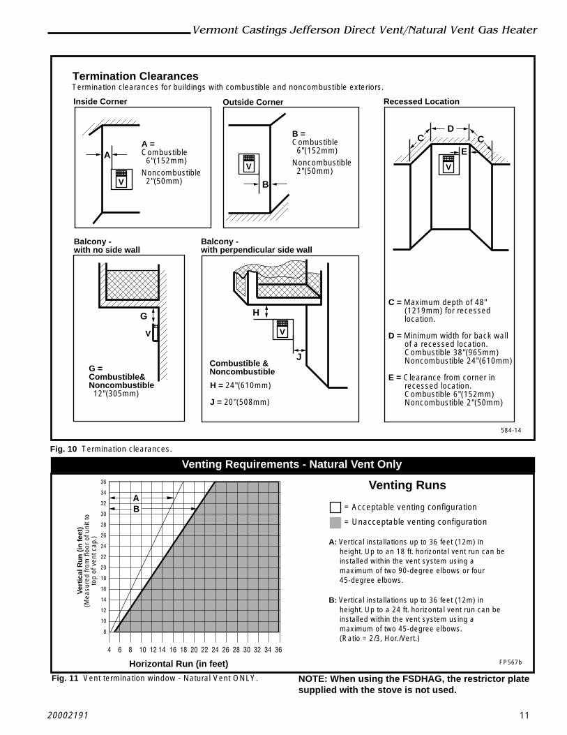
1. Remove stove front. Lift stove front up and thenswing bottom out and away to disengage from thestove body. (Fig. 37)
2. Swing open the swiveling latches at the top left andright corners of the glass frame. (Fig. 12, Page 13)
2222
Vermont Castings Jefferson Direct Vent/Natural Vent Gas Heater
20002191
ST229a
Fig. 37 Remove stove front.
3. Pull the top edge of the glass and frame assemblyaway from the firebox, and lift it off its supports onthe bottom of the firebox face. Place the assemblyout of the way on a flat, padded surface such as acounter protected by a towel.
4. Take the logset out of the firebox if previously in-stalled.
5. Remove the rear log bracket by unfastening thescrew. (Fig. 38)
6. Remove the right and left log bracket assembly byunfastening the two screws which hold the burner inplace. (Fig. 38)
Remove Screws Rear Log Bracket
Pilot
Left & Right LogBracket Assembly ST350
Fig. 38 Remove rear log bracket and left and right logbracket assembly.
7. Hold the burner at the right hand side and lift to clearthe right burner leg. Then pull to the right to clear theinjectors on the left hand side.
8. The air shutter is located on the bottom of the burnerto the left. (Fig. 39) Unfasten the two nuts holdingthe shutter in place. The shutter may be adjustedbetween the factory adjusted 1/2” to fully open.Reassemble the shutter to allow the rear injector air
inlet to close from a minimum 1/2” opening to fullyopen. (Fig. 40) You may have to try more than onceto find the correct air shutter opening for best resultsdepending on your altitude.
9. Refasten the two nuts and assemble the burner intothe unit by sliding the burner in at an angle with theleft side lower than the right side. Slide the left sideonto the injectors. Lower the right hand side downinto place. Make sure the burner is as far left aspossible and the injector shoulders are inside theburner. NOTE: It is very critical to keep the leftburner leg, which holds the injectors, at a 90° angleto the base. (Fig. 41) This keeps the orifices alignedwith tubes on the inside of the burner. Failure to doso could affect the flame appearance and perfor-mance of the unit.
10.Refasten the right and left log bracket assembly.11.Refasten the rear log bracket.12.Replace logs.13.Replace glass and stove front.
Follow lighting instructions on page 26. Check flamecolor appearance. NOTE: Allow stove to burn for atleast 1/2 hour to establish full flame color.
Should color need further adjustment, repeat steps 1 -12 for air shutter adjustment.
Air Shutter(Original Position)
Burner
ST352
Fig. 39 Air shutter in original from-the-factory position.
See Table 1
Front InjectorAir Inlet Air Shutter
(May be adjusted up to fully open)Burner
Rear Injector Air Inlet
ST351
Fig. 40 Air shutter adjusted.

23
Vermont Castings Jefferson Direct Vent/Natural Vent Gas Heater
20002191
90°
Left Burner LegInjector Shoulder
Fig. 41 Be sure to maintain 90° angle at left burner leg.
ST353
Complete the Assembly
• Open the swiveling latches (cams) on the top leftand right corners of the glass frame.
• Position the glass and frame against the firebox byplacing the bottom edge on the brackets on thebottom face of the firebox.
• Swing the assembly against the firebox, and closethe latches firmly against the pins protruding fromthe firebox top.
Install ON/OFF Switch
The switch assembly parts are found in the parts bag.1. Attach switch assembly to left rear side of stove
shroud using two screws and existing holes inshroud. (Fig. 42)
2. Run wires down back of stove, under bottom of rearshroud to valve.
3. Attach wires to valve terminals. (Fig. 43)
SwitchAssembly
Screws
ExistingHoles
ST315
Fig. 42 Attach switch assembly to rear shroud.
PILO
TA
DJ
TP
TH
TP
TH
ST228
Fig. 43 Attach switch wires to valve.
Install the Stove Front
The Front Plate attaches to the stove by four steel tabsthat engage with corresponding cast ribs on the sidesand bottom of the stove body. Position the Front about3” down from stove top and lift the plate to engage theupper tabs behind the adjacent ribs on the sides. (Fig.44) Then lower the plate into position, so that thelower tabs engage with the corresponding ribs at thebottom. (Fig. 45)
When properly installed, the bottom of the Stove Frontcannot be pulled away from the sides without alsolifting it.
Control Door
Lower Tabs EngageRibs in Bottom ST229
Fig. 44 Install Stove Front.
3”
Upper Tabs
Stove Side
Side Rib
Front Tab
Stove Front ST279
Fig. 45 Engage with side ribs.

2424
Vermont Castings Jefferson Direct Vent/Natural Vent Gas Heater
20002191
ThermostatWire / Gauge Maximum Run
18 20 feet16 20 - 40 feet14 up to 60 feet
Thermostat Connection (optional)
Use only a thermostat rated for 500 millivolts.
Check the table below for the appropriate gaugethermostat wire to use for the length of lead required inyour installation.
1. Install the wall thermostat in the desired location andrun the wires to the stove location. Terminate theseleads with 1/4” female connectors.
2. Connect the thermostat wires to the valve. (Fig. 43)
This completes assembly of the Jefferson stove.
25
Vermont Castings Jefferson Direct Vent/Natural Vent Gas Heater
20002191
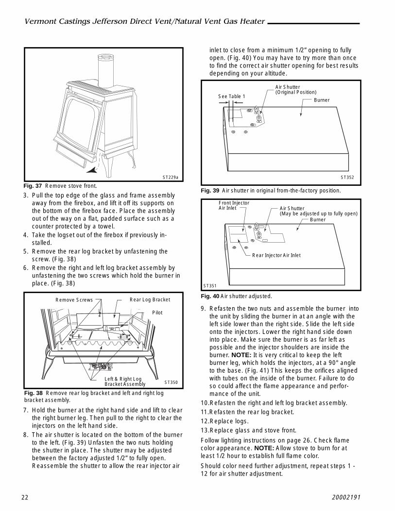
OperationYour First Fire
Read these instructions carefully and familiarizeyourself with the burner controls. Locate the pilotassembly, Figure 46. Follow the lighting instructions onPage 28 exactly.
During the first fire, it is not unusual to smell some odorassociated with new logs, paint and metal beingheated. Odors should dissipate within an hour or so,however, you can open a window to provide fresh air toalleviate the condition.
Pilot and Burner Inspection
Each time you light your heater check that the pilotflame and burner flame pattern are as shown in Figure47 or Figure 48 and Figure 49. If flame patterns areincorrect, turn the heater off. Contact your dealer or aqualified gas technician for assistance. Do not operatethe heater until the pilot flame is correct.
Follow regular maintenance procedures as describedon Page 30.
Fig. 46 Pilot Assembly location.
Thermocouple ST232
Pilot Assembly
Flame & Temperature Adjustment
For stoves equipped with HI/LO valves, flame adjust-ment is accomplished by rotating the HI/LO adjustmentknob located near the center of the gas control valve.(Fig. 47)
ST233
Fig. 48 Correct pilot flame pattern. PSE Pilot.
LO
HI
Turncounterclockwise
to decreaseflame height
Turn clockwiseto increase
flame height
Fig. 47 Flame adjustment knob for Honeywell valve.
Flame Characteristics
It is important to periodically perform a visual check ofthe pilot and the burner flames. Compare them toFigures 48 - 50. If any of the flames appear abnormal,call a service person.
CO105c
Fig. 49 Correct pilot flame pattern. SIT Valve.
ST234
Fig. 50 Correct burner flame pattern.

2626
Vermont Castings Jefferson Direct Vent/Natural Vent Gas Heater
20002191
4. Push in gas control knob slightly and turnclockwise to "OFF". Do not force.
5. Close control access panel.
1. STOP! Read the safety information above.2. Turn off all electrical power to the fireplace.3. For MN/MP/TN/TP appliances ONLY, go on to
Step 4. For RN/RP appliances turn the On/Offswitch to “OFF” position or set thermostat tolowest level.
4. Open control access panel.5. Push in gas control knob slightly and turn
clockwise to "OFF".
10. Push the control knob all the way in and hold.Immediately light the pilot by repeatedlydepressing the piezo spark ignitor until a flameappears. Continue to hold the control knob in forabout one (1) minute after the pilot is lit. Releaseknob and it will pop back up. Pilot should remainlit. If it goes out, repeat steps 5 through 8.
FOR YOUR SAFETY READ BEFORE LIGHTING
• If you cannot reach your gas supplier, call theFire Department
C. Use only your hand to push in or turn the gascontrol knob. Never use tools. If the knob will notpush in or turn by hand, do not try to repair it, call aqualified service technician. Applying force or anyattempted repair may result in a fire or explosion.
D. Do not use this fireplace if any part has been underwater. Immediately call a qualified service techni-cian to inspect the heater and to replace any part ofthe control system and any gas control which hasbeen under water.
A. This heater has a pilot which must be litmanually. When lighting the pilot follow theseinstructions exactly.
B. BEFORE LIGHTING smell all around the heaterarea for gas. Be sure to smell next to the floorbecause some gas is heavier than air and willsettle on the floor.
WHAT TO DO IF YOU SMELL GAS• Do not try to light any fireplace• Do not touch any electric switch• Do not use any phone in your building• Immediately call your gas supplier from a
neighbor's phone. Follow the gas supplier'sinstructions.
To Turn Off Gas To Heater
Lighting And Operating Instructions
1. Turn the On/Off switch to Off position or set thethermostat to lowest setting.
2. Turn off all electric power to the fireplace ifservice is to be performed.
3. Open control access panel.
Lighting Instructions
6. Wait five (5) minutes to clear out any gas. Thensmell for gas, including near the floor. If yousmell gas, STOP! Follow "B" in the safetyinformation above. If you do not smell gas, goto the next step.
7. Remove glass door before lighting pilot. (SeeGlass Frame Removal section).
8. Visibly locate pilot by the main burner.9. Turn knob on gas control counterclockwise
to "PILOT".
• If knob does not pop up when released, stopand immediately call your service technician orgas supplier.• If after several tries, the pilot will not stay lit,turn the gas control knob to "OFF" and call yourservice technician or gas supplier.
11. Replace glass door.12. Turn gas control knob to “ON” position.13. For RN/RP appliances turn the On/Off switch to
“ON” position or set thermostat to desired setting.14. Turn on all electrical power to the fireplace.
WARNING:If you do not follow these instructions exactly, a fire or explosionmay result causing property damage, personal injury or loss of life.
Euro SIT SIT NOVA Honeywell
PILOT
ON
OFFON
PILOT
OF
F
OFF5 4 3
21
OFF
Pilo
t
3/8" - 1/2"

27
Vermont Castings Jefferson Direct Vent/Natural Vent Gas Heater
20002191
Troubleshooting / Honeywell #8420 Gas Control SystemNOTE: Before troubleshooting the gas control system, be sure the external gas shutoff is in the “ON” position.
WARNING: REMOVE THE GLASS PANEL BEFORE PERFORMING ANY GAS CONTROL SERVICE WORK.
SYMPTOM POSSIBLE CAUSES CORRECTIVE ACTION
1. Spark ignitor willnot light
2. Pilot will not stay litafter carefullyfollowing thelighting instructions
3. Pilot lights, no gasto burner, valveknob ON, remoteswitch (rockerswitch) ON
4. Frequent pilotoutage
A. Defective or misalignedelectrode at the pilot
B. Defective ignitor (pushbutton)
A. Defective pilot generator(thermocouple)
B. Defective automatic valveoperator
A. Remote switch or wiresdefective
B. Thermopile may not gener-ate sufficient voltage
C. Plugged burner orifice
D. Defective automatic valveoperator
A. Pilot flame may be too lowor high, (blowing or lifting),causing the pilot to drop out
B. Possible blockage of thevent terminal
Using a match, light pilot. If pilot lights, turn off pilot andpush the ignitor button again. If pilot will not light, checkgap at electrode and pilot - it should be 1/8” to have astrong spark.
Push piezo ignitor button. Check for spark at electrodeand pilot. If there is no spark at the pilot, and electrodewire is properly connected, replace ignitor.
Check pilot flame. It must impinge on the thermocoupleor thermopile. NOTE: This pilot burner assembly usesboth a thermocouple and a thermopile. The thermo-couple operates the pilot flame. Tighten the thermo-couple. The thermopile operates the main valve (ON andOFF). Clean and/or adjust pilot for maximum flameimpingement on thermocouple and thermopile.
Turn valve knob to ‘Pilot’. Maintain flow to pilot; millivoltmeter should read greater than 10mV. If the reading isokay and the pilot does not stay on, replace the gasvalve. NOTE: An interrupter block (not supplied) must beused to conduct this test.
Check rocker switch and wires for proper connection.Use jumper wires across terminals at rocker switch. Ifburner lights, replace rocker switch. If okay, use jumperwires across rocker switch wires at the valve; if burnerlights, wires are faulty or connections are bad.
1. Be sure wire connections from thermopile at gas valveterminals are tight and thermopile is fully inserted intopilot bracket.
2. One of the rocker switch wires may be grounded.Remove rocker switch wires from valve terminals. Ifburner now stays lit, trace rocker switch wiring fromground. It may be grounded to the appliance or thegas supply line.
3. Check the thermopile with a millivolt meter. Takereading at thermopile (“TP” and “TP/TH”) terminals ofgas valve. Should read 325 millivolts minimum whileholding valve knob depressed in PILOT position andwith rocker switch OFF. Replace faulty thermopile ifreading is below specified minimum.
Check burner orifices for debris, and remove.
Turn knob to ON, place rocker switch to ON, millivoltmeter should read greater than 10 mV. If the reading isokay and the burner does not light, replace the valve.
Clean and/or adjust pilot flame for maximum flameimpingement on thermocouple and thermopile.
Check the vent terminal for blockage.

2828
Vermont Castings Jefferson Direct Vent/Natural Vent Gas Heater
20002191
Conversion PrecautionsBefore proceeding, turn control knob on valve to OFFand turn gas supply OFF. Turn OFF any electricity thatmay be going to the appliance.
8. Tighten screw, replace cap.9. Remove the rear log bracket by unfastening the
screw. (Fig. 53)10.Remove the right and left log bracket assembly by
unfastening the two screws which hold the burner inplace. (Fig. 53)
11.Hold the burner at the right hand side and lift to clearthe right burner leg. Then pull to the right to clear theinjectors on the left hand side.
12.Locate pilot. (Fig. 53)13. Replace pilot orifice.
Fuel Conversion InstructionsWARNING! This conversion kit shall be installed bya qualified service agency in accordance with themanufacturer’s instructions and all applicablecodes and requirements of the authority havingjurisdiction. If the information in these instructionsis not followed exactly, a fire, explosion or produc-tion of carbon monoxide may result causing prop-erty damage, personal injury or loss of life. Thequalified service agency is responsible for theproper installation of this kit. The installation is notproper and complete until the operation of theconverted appliance is checked as specified in themanufacturer’s instructions supplied with the kit.
CAUTION: The gas supply shall be shut off prior todisconnecting the electrical power, before proceed-ing with the conversion.
PILOT
ON
OFF
PILO
TAD
J
LOHI
MainGas Line
Gas Supply InletST226
Fig. 51 Attach the gas line to the left side of the valve.
Conversion Procedure1. Remove stove front. Lift stove front up and then swing
bottom out and away to disengage from the stovebody. (Fig. 59, Page 31)
2. Swing open the swiveling latches at the top left andright corners of the glass frame. (Fig. 60, Page 31)
3. Pull the top edge of the glass and frame assemblyaway from the firebox face. Place the assembly out ofthe way on a flat, padded surface such as a counterprotected by a towel.
4. Remove the logset from the firebox.5. Remove cap from Hi-Lo knob. This can be accom-
plished by lifting the plastic cap off the screw. (Fig. 52)6. Remove the screw from center of Hi-Lo knob with
small screwdriver turning counterclockwise. (Fig. 52)7. Insert blue painted screw when converting to natural
gas and red painted screw when converting to LP.
LO
HI
LO
HI
Cap
Hi-LoKnob
Lift Open
Center Screw CO100
Fig. 52 Remove center screw from Hi-Lo knob.
Pilot Type 1
• Remove pilot hood by lifting up. (Fig. 54) NOTE: Donot remove snap ring to remove pilot hood. NOTE: Itis not necessary to remove the pilot tube for conver-sion.
• Remove pilot orifice with allen wrench. (Fig. 55)
• Install the conversion orifice.
• Reinstall pilot hood. Be sure to align hood with indextab.
Pilot type 2
• Loosen pilot hood by turning counterclockwise usinga 7/16” wrench. (Fig. 56) NOTE: You may use pen-etrating oil to prevent pilot hood threads from seizingup.
Remove Screws Rear Log Bracket
Pilot
Left & Right LogBracket Assembly ST350
Fig. 53 Remove rear log bracket and left and right log bracketassembly.

29
Vermont Castings Jefferson Direct Vent/Natural Vent Gas Heater
20002191
16.Replace burner. Slide the burner in at an angle withleft side lower than the right side. Slide the left sideonto the injectors, making sure the burner leg remainsat a 90° angle to the base. Lower the right hand sidedown in to place. Make sure the burner is as far left aspossible and the injector shoulders are inside theburner.
NOTE: It is very critical to keep the left burner leg, whichholds the injectors, at a 90° angle to the base. (Fig.58) This keeps the orifices aligned with the tubesinside burner. Failure to do so could affect the flameappearance and performance of the unit.
19.Place conversion label on valve.20.Reinstall the right and left log bracket assembly.21.Reinstall the rear log bracket.22.Replace logs.23.Replace glass and stove front.Conversion is complete.
90°
Left Burner Leg
Injector Orifices
ST353a
Fig. 58 Remove and replace injector orifices.
Table 2. Injector Orifice Size MatrixConversion to Natural Gas Input (BTU/h)
Kit # Front Part # Rear Part # Minimum Maxi,mum000-5021 #54 / .055” 20000130 #44 / .086” 30000334 19,000 28,000
Conversion to LP Input (BTU/h)Kit # Front Part # Rear Part # Minimum Maximum
000-5022 #69 / .029” 30000513 #54 / .055” 20000130 20,000 28,000
Pilot Hood
PilotBracket
CO105a
Fig. 54 Remove pilot hood.
Index Tab
Snap Ring
Allen Wrench
CO106a
Fig. 55 Remove pilot orifice.
• Remove pilot orifice with needlenose pliers. (Fig. 57)NOTE: Use a wrench to hold pilot tube in place whileremoving the orifice.
• Install the conversion orifice.
• Reinstall pilot hood and tighten until mark on pilothood aligns with mark on pilot bracket.
14.Remove injector orifices from left burner leg using 1/2” wrench. (Fig. 58)
15.Install conversion orifices. (Refer to Table 2)NOTE: Be sure burner leg remains at a 90° angle to
firebox base after conversion.
Pilot Hood
IndexMarks
Pilot BracketCO105
Fig. 56 Remove pilot hood.
PilotOrifice
CO106b
Fig. 57 Remove pilot orifice.
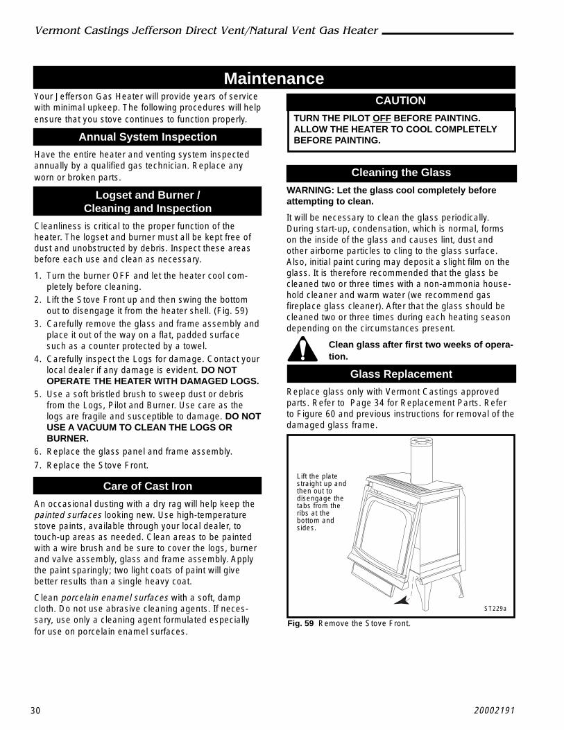
3030
Vermont Castings Jefferson Direct Vent/Natural Vent Gas Heater
20002191
MaintenanceYour Jefferson Gas Heater will provide years of servicewith minimal upkeep. The following procedures will helpensure that you stove continues to function properly.
Annual System Inspection
Have the entire heater and venting system inspectedannually by a qualified gas technician. Replace anyworn or broken parts.
Logset and Burner /Cleaning and Inspection
Cleanliness is critical to the proper function of theheater. The logset and burner must all be kept free ofdust and unobstructed by debris. Inspect these areasbefore each use and clean as necessary.
1. Turn the burner OFF and let the heater cool com-pletely before cleaning.
2. Lift the Stove Front up and then swing the bottomout to disengage it from the heater shell. (Fig. 59)
3. Carefully remove the glass and frame assembly andplace it out of the way on a flat, padded surfacesuch as a counter protected by a towel.
4. Carefully inspect the Logs for damage. Contact yourlocal dealer if any damage is evident. DO NOTOPERATE THE HEATER WITH DAMAGED LOGS.
5. Use a soft bristled brush to sweep dust or debrisfrom the Logs, Pilot and Burner. Use care as thelogs are fragile and susceptible to damage. DO NOTUSE A VACUUM TO CLEAN THE LOGS ORBURNER.
6. Replace the glass panel and frame assembly.
7. Replace the Stove Front.
Care of Cast Iron
An occasional dusting with a dry rag will help keep thepainted surfaces looking new. Use high-temperaturestove paints, available through your local dealer, totouch-up areas as needed. Clean areas to be paintedwith a wire brush and be sure to cover the logs, burnerand valve assembly, glass and frame assembly. Applythe paint sparingly; two light coats of paint will givebetter results than a single heavy coat.
Clean porcelain enamel surfaces with a soft, dampcloth. Do not use abrasive cleaning agents. If neces-sary, use only a cleaning agent formulated especiallyfor use on porcelain enamel surfaces.
CAUTION
TURN THE PILOT OFF BEFORE PAINTING.ALLOW THE HEATER TO COOL COMPLETELYBEFORE PAINTING.
Cleaning the Glass
WARNING: Let the glass cool completely beforeattempting to clean.
It will be necessary to clean the glass periodically.During start-up, condensation, which is normal, formson the inside of the glass and causes lint, dust andother airborne particles to cling to the glass surface.Also, initial paint curing may deposit a slight film on theglass. It is therefore recommended that the glass becleaned two or three times with a non-ammonia house-hold cleaner and warm water (we recommend gasfireplace glass cleaner). After that the glass should becleaned two or three times during each heating seasondepending on the circumstances present.
Clean glass after first two weeks of opera-tion.
Glass Replacement
Replace glass only with Vermont Castings approvedparts. Refer to Page 34 for Replacement Parts. Referto Figure 60 and previous instructions for removal of thedamaged glass frame.
ST229a
Fig. 59 Remove the Stove Front.
Lift the platestraight up andthen out todisengage thetabs from theribs at thebottom andsides.

31
Vermont Castings Jefferson Direct Vent/Natural Vent Gas Heater
20002191
Gasket ReplacementThe Jefferson Gas Heater uses a ‘tadpole’ type gasketto seal between the glass panel and the frame. In time,this gasket can become brittle and compressed andshould be replaced. New gasket is available from yourdealer.
Shut off the gas supply and allow the stove to cool.Wear safety goggles and a dust mask.
1. Remove the Front, Glass Frame and Glass Panel.(Figs. 59 & 60) Remove the old gasket. Use a razorblade to separate the glass and gasket from theframe, and to clean the glass of any remainingcement or bits of gasket. Use a cold chisel if neces-sary.
2. Determine the correct length of gasket by laying itout around the edge of the glass. Allow an extra 1 -2” (25-50mm). Mark the spot to be cut. Use a utilityknife.
3. Starting on a long edge, remove about 6” of theprotective paper strip and apply the flat adhesiveface of the gasket around the outside-facing edge ofthe panel. Continue around the panel, applying about 6” at a time and being careful to not stretch thematerial. Do not overlap the gasket ends. (Fig. 61)
4. Apply a thin bead of high temperature siliconerubber sealant along the inside corner of the glassframe, all around the perimeter. Place the flatgasketed side of the glass panel back into the steelframe. Pinch the rounded inside-facing gasketmaterial to bulk it up.
5. Replace the glass frame and front panel as previ-ously described.
Check the Gas Flame RegularlyTo ensure that the stove is operating properly, checkthe flames periodically to confirm that they matchFigure 62. The flames will be blue during the first 15-20minutes of operation, and will gradually turn to yellowafter that.
Do not use your stove if the flame pattern differs fromthat shown here. Contact your Vermont Castings dealeror a qualified technician for help.
Inspect the Vent System AnnuallyHave the vent system inspected annually by a qualifiedtechnician. Shut off the main gas supply before inspect-ing the system. Both the inner exhaust pipe and theouter combustion supply pipe must be checked toconfirm that they are unblocked and in good condition.
Stove DisassemblyIf there is ever a need to remove the firebox assemblyfrom the stove shell, support the firebox with solidstands about 6” (150mm) tall under the left and rightouter edges of the firebox base. Do not set the fireboxassembly directly on the floor; this can damage thecontrol valve and/or the gas lines from the valve to thefirebox.
Before removing the firebox from the shell, disconnectthe on/off switch wires from the valve. If the assemblyincludes the optional fan, disconnect the fan rheostat. Ifthe installation includes a wall thermostat, disconnectthe thermostat leads from valve.
Disconnection and reconnection to the gas line shouldonly be done by a qualified gas service technician.
Upon reinstallation, the vent system must be sealed tothe firebox as shown in the installation section, Page14. Also be sure the logs are placed in the fireboxcorrectly, as shown on Page 20.
ST179
Fig. 61 Wrap the gasket material around the outside edge ofthe glass.
ST234
Fig. 62 Correct flame pattern.
ST208a
Fig. 60 Release the latches to release the glass frame.

3232
Vermont Castings Jefferson Direct Vent/Natural Vent Gas Heater
20002191
NOTE: IF ANY OF THE ORIGINAL WIRE, ASSUPPLIED WITH THE APPLIANCE, MUST BEREPLACED, IT MUST BE REPLACED WITH TYPESF-2, 200°C WIRE OR ITS EQUIVALENT.
Wiring Diagrams
ST124c
Fig. 61 Jefferson on/off switch and optional thermostatcircuit.
Optional ThermostatWiring
On/Off SwitchWiring
ST124b
OFF ON
The
rmop
ileBla
ck
Black
TP/TH
TP
TH
Thermostat(Optional)
The
rmop
ileBla
ck
Black
TP/TH
TP
TH
FAN JUNCTION BOX
FANPOWERCORD
Strain Relief
Chassis Ground
BLK
GRN
GRN
WHT
ON / OFFRheostat
ChassisGround
RHEOSTAT / SNAPSTATBOX
Snapstat
BLKBLK
BLK
BLKBLK
WHT
MOTOR
SNAPSTAT
ON/OFFRHEOSTAT
WHT
WH
T
BLKBLK
BLK
GR
N
BLK
Schematic Diagram
ST234
ST153
Fig. 65 Jefferson fan circuit.
TH
TP
THTP
Draft Hood
Vent Safety Switch
GasValve
ST359
Fig. 64 Draft Hood Adapter wiring.

33
Vermont Castings Jefferson Direct Vent/Natural Vent Gas Heater
20002191
1a
1b
1c
1d
1e
PILOT
ON
OF
F
PILOTADJ
LOHI
TPTH THTP
CEMENT
2
3
6
9
87
10a,b
4
18
19
20
21
23
22
25
26
27
28
29
30
11a
12 13 1415
17
16
11b
31
5a,b
Vermont Castings, Majestic Products reserves the right to make changes in design, materials, specifications, prices and discontinue colors andproducts at any time, without notice.
2191
Jefferson Direct Vent/Natural Vent Gas HeaterModels 2820, 2822, 2823, 2825, 2827, 2828
Ref. Description JDV1. Gas Log Set - JDV 20002182
1a. Log, Back - JDV 200021831b. Log, Left Upper - JDV 200021871c. Log, Right Upper - JDV 200021861d. Log, Left - JDV 200021851e. Log, Right - JDV 200021842. Grille, JDV 300006853. Screen, Grille - JDV 300006654. Furnace Cement 12061225. Manifold Assembly 200037396. Lava Rocks Burner 57897

3434
Vermont Castings Jefferson Direct Vent/Natural Vent Gas Heater
20002191
Jefferson Direct Vent/Natural Vent Gas Heater (continued)
Models 2820, 2822, 2823, 2825, 2827, 2828Ref. Description JDV
7. Gasket, Glass - Med. Knit - RDV40 12037028. Glass, JDV 200021209. Glass Frame Assembly - JDV 20002117
10a. Valve RN Honeywell VS8420E 2038 1000178210b. Valve RP Honeywell VS8420E 2020 1000175911a. Pilot Assembly 3Way N/DV RN 0.199.706 10002264
Pilot Assembly 3Way N/DV RP 0.199.703 1000226511b. Pilot, PSE - NA175 20001115
Pilot, PSE - LP175 2000111612. Thermocouple 24” 53373
753113713. Electrode Ignitor w/ cable SIT24 1000129714. Pilot Top Convertible 1000226615. Thermopile 18” RS 51827
753311316. Nut Electrode SIT #0.974.144 5788617. Tubing Pilot w/Fittings 1/8 x 24” 1000129618. Burner Housing Assembly NG/LP 2000221419. Grate, Burner - JDV 2000216720. Wiring Harness - FSDV32RN/JDV 1000258221. Switch ON/OFF - RN/RP Models 3000087422. Front, JDV Refer to Enamel Parts Chart Page 3423. Door, Control - JDV 30000686
24a. Orifice Hood - #69 - Front - LP 3000051324b. Orifice Hood - #54 - Front - NG 2000013024c. Orifice Hood - #54 - Rear - LP 2000013024d. Orifice Hood - #44 - Rear - NG 30000334
25. Bracket, Right Log - JDV 2000216626. Bracket, Left Log - JDV 2000216527. Front Handle Assembly - JDV/Parts 500424028. Handle, Damper - Maplewood - BLK 160066429. Gasket, Base Pan - JDV 2000228230. Gasket, Base Pan Inner 2000256631. Sensor 2450 CMG-8184-0032 10002013
Fuel Conversion Kits:Conversion Kit, NG to LP - JDV/SDV30R Kit #000-5022Conversion Kit, LP to NG - JDV/SDV30R Kit #000-5021
Shell Enamel Part NumbersModel Color Top Left Right Front
Number End End2820, 2825 Classic 30000680 30000682 30000681 300006832822, 2827 Midnight 30000717 30000720 30000719 300007212823, 2828 Green 30000753 30000726 30000725 30000727

35
Vermont Castings Jefferson Direct Vent/Natural Vent Gas Heater
20002191
Optional AccessoriesFan Kits
FK28 Fan
The FK28 fan helps distribute heated air from withinthe firebox out into the room. The fan is controlled by asnapstat that turns power on and off as the fireboxtemperature rises above and falls below a presettemperature. A rheostat provides for variable fanspeeds.
Specifications
115 Volt / 60Hz / .75 Amps
Maintenance
The fan itself does not require regular maintenance,however, periodic cleaning of the fan and thesurrounding area is required.
Installation
Refer to Page 13 for installation instructions.
Remote Controls
The remote control allows you to turn the heater on oroff from anywhere in the room. Refer to Page 40 forwiring diagrams.
Model Functions Controlled
MRC1 ON/OFFMRC2 ON/OFF and TemperatureMRC3 ON/OFF and Temperature control
with a digital display and aprogrammable 24 hour clock
IMT Wall mounted thermostat control
Decorative Rings
7” brass or charcoal gray rings are available to add adecorative touch to the exposed stove pipe.
Model Description
7FSDRG/4 7” Charcoal Gray Rings (4)7FSDRP/4 7” Polished Brass Rings (4)

BASIC WARRANTY
The Vermont Castings, Majestic Products Company (hereinafterreferred to collectively as the Company) warrants that your newVermont Castings or Majestic Gas Fireplace/Stove is free frommanufacturing and material defects for a period of one year from thedate of purchase, subject to the following conditions and limitations.
EXTENDED LIFETIME WARRANTY
The heat exchanger, where applicable, and combustion chamber ofevery Vermont Castings or Majestic gas product is warranted for lifeagainst through wall perforation. All appliances equipped with anInsta-Flame Ceramic Burner have limited lifetime coverage on theceramic burner plaque. Warrantees are made to the original ownersubject to proof of purchase and the conditions and limitations listedon this Warranty Document
COMPONENT WARRANTY
CAST IRON: All external and internal cast iron parts are warranted for aperiod of three years.
Note: On porcelain enamel finished external parts and accessoriesThe Company offers no Warranty on chipping of enamel surfaces.Inspect all product prior to accepting it for any damage to the enamel.
The salt air environment of coastal areas or a high humidityenvironment can be corrosive to the porcelain enamel finish. Theseconditions can cause rusting of the cast iron beneath the porcelainenamel finish, which will cause the finish to flake off.
Dye lot variations with replacement parts and/or accessories canoccur and are not covered by warranty.
GLASS DOORS: Glass doors are covered for a period of one year.Glass doors are not warranted for breakage due to misuse oraccident. Glass doors are not covered for discoloration or burned instains due to environmental issues, or improper cleaning andmaintenance.
BRASS PLATED PARTS AND ACCESSORIES: Brass parts should becleaned with Lemon oil only. Brass cleaners cannot be used. Mortarmix and masonry cleaners may corrode the brass finish. TheCompany will not be responsible for, nor will it warrant any brass partswhich are damaged by external chemicals or down draft conditions.
GAS VALVES: Gas valves are covered for a period of one year
ELECTRONIC AND MECHANICAL COMPONENTS: Electronic andmechanical components of the burner assembly are covered for oneyear. All steel tube burners are warranted for one year.
ACCESSORIES: Unless otherwise noted all components and VermontCastings, Majestic Products company supplied accessories are coveredfor a period of one year.
CONDITIONS AND LIMITATIONS
• This new Vermont Castings or Majestic product must be installed bya competent, authorized, service contractor. A licensed technician,as prescribed by the local jurisdiction must perform any installation/service work. It must be installed and operated at all times inaccordance with the Installation and Operating instructions furnishedwith the product. Any alteration, willful abuse, accident, or misuse ofthe product shall nullify this warranty.
• This warranty is non-transferable, and is made to the original owner,provided that the purchase was made through an authorized supplierof the Company.
• The customer must pay for any Authorized Dealer in-home travel feesor service charges for in-home repair work. It is the dealers optionwhether the repair work will be done in the customer’s home or in thedealer’s shop.
• If upon inspection, the damage is found to be the fault of themanufacturer, repairs will be authorized at no charge to the customerparts and/or labor.
• Any part and/or component replaced under the provisions of thiswarranty is covered for six months or the remainder of the originalwarranty, whichever is longest.
• This warranty is limited to the repair of or replacement of part(s) foundto be defective in material or workmanship, provided that such part(s)have been subjected to normal conditions of use and service, aftersaid defect is confirmed by the Company’s inspection.
• The company may, at its discretion, fully discharge all obligations withrespect to this warranty by refunding the wholesale price of thedefective part(s)
• Any installation, labor, construction, transportation, or other relatedcosts/expenses arising from defective part(s), repair, replacement, orotherwise of same, will not be covered by this warranty, nor shall theCompany assume responsibility for same. Further, the Company willnot be responsible for any incidental, indirect, or consequentialdamages except as provided by law.
• SOME STATES DO NOT ALLOW FOR THE EXCLUSION ORLIMITATIONS OF INCIDENTAL AND CONSEQUENTIAL DAMAGESOR LIMITATIONS ON HOW LONG AN IMPLIED WARRANTY LASTS,SO THE ABOVE LIMITATIONS MAY NOT APPLY TO YOURCIRCUMSTANCES. THIS WARRANTY GIVES YOU SPECIFICRIGHTS AND YOU MAY HAVE OTHER RIGHTS WHICH VARYFROM STATE TO STATE.
• All other warranties-expressed or implied- with respect to the product,its components and accessories, or any obligations/liabilities on thepart of the Company are hereby expressly excluded.
• The Company neither assumes, nor authorizes any third party toassume on its behalf, any other liabilities with respect to the sale ofthis Vermont Castings, Majestic product
• The warranties as outlined within this document do not apply tochimney components or other non Vermont Castings, Majesticaccessories used in conjunction with the installation of this product..
• Damage to the unit while in transit is not covered by this warranty butis subject to claim against the common carrier. Contact the dealerfrom whom you purchased your fireplace/stove (do not operate theappliance as this might negate the ability to process the claim with thecarrier).
• The Company will not be responsible for:
a) Down drafts or spillage caused by environmental conditions suchas near-by trees, buildings, roof tops, hills, or mountains.
b) Inadequate ventilation or negative air pressure caused bymechanical systems such as furnaces, fans, clothes dryers, etc.
• This warranty is void if:
a) The fireplace has been operated in atmospheres contaminatedby chlorine, fluorine, or other damaging chemicals.
b) The fireplace has been subjected to prolonged periods ofdampness or condensation
c) Any damages to the fireplace, combustion chamber, heatexchanger or other components due to water, or weather damage,which is the result of but not limited to, improper chimney/ventinginstallation.
d) Any alteration, willful abuse, accident, or misuse of the producthas occurred.
IF WARRANTY SERVICE IS NEEDED…
1) Contact your supplier. Make sure you have yourwarranty, your sales receipt, and the model/serialnumber of your Vermont Castings, Majesticproduct.
2) DO NOT ATTEMPT TO DO ANY SERVICE WORKYOURSELF.
LIMITED LIFETIME WARRANTYPRODUCT COVERED BY THIS WARRANTYAll Vermont Castings gas stoves, gas inserts, and gas fireplaces, and all Majestic or Northern Flame brand gas fireplacesequipped with an Insta-Flame Ceramic Burner, or standard steel tube burner.