JEDEC STANDARD - Sager Electronics€¦ · Any test samples with tin-based finishes may be studied,...
34
JEDEC STANDARD Measuring Whisker Growth on Tin and Tin Alloy Surface Finishes JESD22A121 MAY 2005 JEDEC SOLID STATE TECHNOLOGY ASSOCIATION
Transcript of JEDEC STANDARD - Sager Electronics€¦ · Any test samples with tin-based finishes may be studied,...

JEDEC STANDARD Measuring Whisker Growth on Tin and Tin Alloy Surface Finishes JESD22A121 MAY 2005 JEDEC SOLID STATE TECHNOLOGY ASSOCIATION

NOTICE
JEDEC standards and publications contain material that has been prepared, reviewed, and approved through the JEDEC Board of Directors level and subsequently reviewed and approved by the
JEDEC legal counsel.
JEDEC standards and publications are designed to serve the public interest through eliminating misunderstandings between manufacturers and purchasers, facilitating interchangeability and
improvement of products, and assisting the purchaser in selecting and obtaining with minimum delay the proper product for use by those other than JEDEC members, whether the standard is to be
used either domestically or internationally.
JEDEC standards and publications are adopted without regard to whether or not their adoption may involve patents or articles, materials, or processes. By such action JEDEC does not assume any liability to any patent owner, nor does it assume any obligation whatever to parties adopting the
JEDEC standards or publications.
The information included in JEDEC standards and publications represents a sound approach to product specification and application, principally from the solid state device manufacturer
viewpoint. Within the JEDEC organization there are procedures whereby a JEDEC standard or publication may be further processed and ultimately become an ANSI/EIA standard.
No claims to be in conformance with this standard may be made unless all requirements stated in
the standard are met.
Inquiries, comments, and suggestions relative to the content of this JEDEC standard or publication should be addressed to JEDEC at the address below, or call (703) 907-7559 or www.jedec.org
Published by
©JEDEC Solid State Technology Association 2005 2500 Wilson Boulevard
Arlington, VA 22201-3834
This document may be downloaded free of charge; however JEDEC retains the copyright on this material. By downloading this file the individual agrees not to
charge for or resell the resulting material.
PRICE: Please refer to the current Catalog of JEDEC Engineering Standards and Publications online at
http://www.jedec.org/Catalog/catalog.cfm
Printed in the U.S.A. All rights reserved
PLEASE!
DON’T VIOLATE THE
LAW!
This document is copyrighted by JEDEC and may not be reproduced without permission.
Organizations may obtain permission to reproduce a limited number of copies
through entering into a license agreement. For information, contact:
JEDEC Solid State Technology Association 2500 Wilson Boulevard
Arlington, Virginia 22201-3834 or call (703) 907-7559


JEDEC Standard No. 22A121
-i- Test Method A121
Test Method for Measuring Whisker Growth on Tin and Tin Alloy Surface Finishes Disclaimer This document is not a qualification standard. It contains a suite of recommended tin whisker growth tests. If these common tests are adopted, then the industry can collect common and comparable data that may improve the understanding of the fundamentals of whisker growth and allows comparisons between technologies. Tests in this document may be changed in the future as a better understanding of the mechanisms causing tin whisker growth is developed. Based on a variety of testing and data review from around the globe, three test conditions have been identified that appear to be suitable for monitoring tin whisker growth. The three test conditions include two isothermal conditions with controlled humidity and a thermal cycling condition. However, these test conditions have not been correlated with longer environmental exposures of components in service. Thus, there is at present no way to quantitatively predict whisker lengths over long time periods based on the lengths measured in the short-term tests described in this document. At the time of writing, the fundamental mechanisms of tin whisker growth are not fully understood and acceleration factors have not been established. Certain applications, e.g., military or aerospace, may require additional and/or different tin whisker tests or evaluations. Introduction The predominant terminal finishes on electronic components have been Sn-Pb alloys. As the industry moves toward Pb-free components and assembly processes, the predominant terminal finish materials will be pure Sn and alloys of Sn, including Sn-Bi and Sn-Ag. Pure Sn and Sn-based alloy electrodeposits and solder-dipped finishes may grow tin whiskers, which could electrically short across component terminals or break off the component and degrade the performance of electrical or mechanical parts.

JEDEC Standard No. 22A121
Test Method A121 -ii-

JEDEC Standard No. 22A121 Page 1
-i- Test Method A121
TEST METHOD A121
Test Method for Measuring Whisker Growth on Tin and Tin Alloy Surface Finishes (From JEDEC Board Ballot JCB-05-58, formulated under the cognizance of the JC-14.1 Subcommittee on Reliability Test Methods for Packaged Devices.) 1 Scope The methodology presented in this document, see Annex A for process flow, is applicable for studying tin whisker growth from finishes containing a predominance of tin (Sn). This test method may not be sufficient for applications with special requirements, e.g., military or aerospace. Additional requirements may be specified in the appropriate requirements document. The purpose of this standard is to:
• Provide an industry-standardized suite of tests for measurement and comparison of whisker propensity for different plating or finish chemistries and processes.
• Provide a consistent inspection protocol for tin whisker examination.
• Provide a standard reporting format. 2 Normative references JESD22-A104, Standard for Temperature Cycling IPC 7530, Guidelines for Temperature Profiling for Mass Soldering (Reflow & Wave) Processes 3 Terms and definitions 3.1 total axial whisker length: The distance between the finish surface and the tip of the whisker that would exist if the whisker were straight and perpendicular to the surface. NOTE For tin whiskers that bend and change directions, the total axial length can be estimated by adding all of the straight subdivisions of the whisker. (See Figure 5.)

JEDEC Standard No. 22A121 Page 2
Test Method A121
3 Terms and definitions (cont’d) 3.2 whisker: A spontaneous columnar or cylindrical filament, usually of monocrystalline metal, emanating from the surface of a finish. (See Annex C for example pictures of tin whiskers.) NOTE 1 For the purpose of this document, whiskers have the following characteristics:
• An aspect ratio (length/width) greater than 2 • Can be kinked, bent, or twisted • Usually have a uniform cross-sectional shape • Typically consist of a single columnar filament that rarely branches • May have striations along the length of the column and/or rings around the circumference of
the column • Length of 10 microns or more. Features less than 10 microns may be deemed important for
research but are not considered significant for this test method.
NOTE 2 Whiskers are not to be confused with dendrites: fern-like growths on the surface of a material which can be formed as a result of electromigration of an ionic species or produced during solidification. (See Annex D for a picture of a typical solidification dendrite.) 3.3 whisker density: The number of whiskers per unit area on a single lead or coupon area. 3.4 whisker growth: Measurable changes in whisker length and/or whisker density after exposure to a whisker test condition for a certain duration or number of cycles. 3.5 whisker test coupon: A piece of metal of specified size and shape that is plated or dipped with a tin finish for the purpose of measuring the propensity for whisker formation and growth. 4 Apparatus 4.1 Temperature cycling chambers Air to air temperature cycling chamber(s), capable of cycling from -55 (+0/-10) °C to +85(+10/-0) °C or from -40(+0/-10) °C to +85(+10/-0) °C. The temperature cycling chamber(s) must be able to satisfy the cycle conditions defined in Table 4.

JEDEC Standard No. 22A121 Page 3
Test Method A121
4 Apparatus (cont’d) 4.2 Temperature humidity chambers Temperature–humidity (T&H) chambers capable of non-condensing 60 ±5 °C, 87 +3/-2% RH and 30 ±2 °C, 60 ±3% RH environment. NOTE 1 The elevated temperature–humidity condition of 60 ±5 °C, 87 +3/-2% RH is close to the condensation point. If water condenses on the tin finish during environmental exposure, the condensed moisture and resulting corrosion may affect the final test results. To prevent condensation in the T & H chamber, the chamber dry-bulb temperature must exceed the wet-bulb temperature at all times by not less than 2.4 °C (or equivalent for electronic sensors). Before opening of the chamber door for loading and unloading, the chamber temperature and humidity should be ramped down sufficiently close to room ambient (recommended within 10 °C and 10% RH) to prevent condensation on the test samples and chamber walls. NOTE 2 During operation, condensation is most likely to occur on the T & H test chamber walls and ceiling; therefore, it is recommended that the test samples be sufficiently shielded from any condensed water that may drip from the chamber ceiling and/or walls onto the samples. NOTE 3 When loading the test samples into the T & H test chamber, the sample temperature must be sufficiently higher than the chamber ambient temperature to avoid condensation on the test samples. It is recommended that the test samples and all sample trays or holders be preheated (to a temperature equal to the test temperature of the T & H test chamber) in a dry-bake oven prior to loading them into the T & H test chamber. NOTE 4 Frequent wet-bulb maintenance is required for proper control of this test condition. 4.3 Optical stereomicroscope (Optional) Optical stereomicroscope with adequate lighting capable of 50X to 150X magnification and capable of detecting whiskers with a minimum axial length of 10 microns, per Annex B. If tin whiskers are measured with an optical system, then the system must have a stage that is able to move in three dimensions and rotate, such that whiskers can be positioned perpendicular to the viewing direction for measurement. 4.4 Optical microscope (Optional) Optical microscope with adequate lighting capable of 100X to 300X magnification and capable of measuring whiskers with a minimum axial length of 10 microns, per Annex B. For tin whisker measurements, the optical system must have a stage that is able to move in three dimensions and rotate, such that whiskers can be positioned perpendicular to the viewing direction for measurement. 4.5 Scanning electron microscope Scanning electron microscope (SEM) capable of at least 250X magnification. An SEM fitted with an X-ray detector is recommended for elemental identification.

JEDEC Standard No. 22A121 Page 4
Test Method A121
4 Apparatus (cont’d) 4.6 Convection reflow oven (Optional) A convection reflow system capable of achieving the reflow profiles of Table 3. 5 Sample requirements and optional preconditioning For specific requirements of tin finishes, the relevant test conditions, read points, and durations shall be described in a test plan agreed upon by the supplier and user. For comparing various finishes for whisker propensity, it is recommended that all three conditions defined in Table 4 be used and that sufficient test time be allocated to allow for the tin whisker incubation period to expire (typically up to 3000 hours). In addition, each test condition is to be performed independently on separate samples. 5.1 Test samples Any test samples with tin-based finishes may be studied, including Sn-Pb finishes. Sample types may include experimentally plated or tin-finished coupons or components, or production-plated/finished electronic components. However, coupons may not be representative of final product because of processes, such as lead trim and form. 5.1.1 Sample size The measurement of maximum whisker length may be significantly influenced by the amount of surface examined because whisker appearance and length are distributed over a range. Examination of large areas may result in a larger maximum whisker length than would be detected by examining a small area. In fact, whiskers may not occur on a particular sample or termination even though other samples and terminations from the same plating or finish lot exhibit significant whisker growth. Therefore, if the total area inspected is not held constant, data will not be directly comparable among different experiments. 5.1.1.1 Electronic components with leads For research and comparison of finished components, plating baths, processes, etc, regarding propensity for whisker growth, a minimum of 96 terminations/leads on at least six samples, for each test condition at each inspection read out, are required to attain a meaningful detection level. The number of samples may need to be adjusted in order to obtain a total of 96 terminations/leads. Components should have completed all manufacturing operations. For consistency and traceability, if applicable to package type, choosing corner leads is recommended. For finished components with large terminations, Table 1 may be used to reduce the number of terminations that are recommended for inspection.

JEDEC Standard No. 22A121 Page 5
Test Method A121
5.1.1 Sample size (cont’d) 5.1.1.2 Test coupons For comparison purposes, if using coupons, a total inspection area of at least 75 mm2 on at least 3 coupons is required for each test condition. For small coupons, it is recommended that there be sufficient coupons so that the total area inspected adds up to a minimum of 75 mm2, as described in Table 1.
Table 1 — Details on the number of test samples and terminations required for comparison of screening inspection data. The number of terminations required for
inspection depends on the tin-finished area of each termination.
Sample Type
Tin Finished Area [1]
Minimum Number
of Samples
Minimum Total
Inspection Area for
Screening Inspection
Minimum Inspection
Surface Area per Sample for Screening Inspection
Minimum Total Number of Inspection Areas for Screening
Inspection [2]
Coupons < 25 mm2 3 75 mm2 Top and two sides of coupon
75 mm2 ÷ (Plated area on top and 2 sides of coupon)
Coupons ≥ 25 mm2 3 75 mm2 Top and two sides up to a total
of 25 mm2
3
Components < 0.85 mm2 6 75 mm2 Top and 2-3 sides of termination
96
Components ≥ 0.85 mm2 6 75 mm2 Top and 2-3 sides of termination
75 mm2 ÷ (Plated area on top and
2-3 sides of termination)
NOTE 1 See Figures 2, 3, and 4 for detailed definition of the plated/finished area for inspection. NOTE 2 For large terminations, more than one inspection area may exist on the same termination. The same 6 components or 3 coupons for each test condition may be evaluated at all sequential read outs, including the final readout. Hence, to study a single finish, 18 component or 9 coupon samples are required to complete the three test conditions. Alternatively, the test may be started with sufficient test samples to inspect 6 different component or 3 coupon samples at each read out. In this case, the number of test samples required will be a minimum of 18 component or 9 coupon samples times the number of read out points during the test. (For example, if a finish is studied in temperature cycling for 2000 cycles with read outs performed at 500, 1000, 1500, and 2000 cycles, then 24 component samples are required just for this test condition.) If a more accurate determination of growth kinetics is needed, it is recommended that the same test samples be used for each sequential read out instead of using re-populated samples.

JEDEC Standard No. 22A121 Page 6
Test Method A121
5.1 Test samples (cont’d) 5.1.2 Optional test sample preconditioning Table 2 lists optional test sample preconditioning treatments that are recommended prior to all subsequent Sn whisker growth tests. If the test method described in this standard is used as part of a tin finish qualification, then the user and supplier must agree on the precondition requirements before commencement of testing.
Table 2 — Optional Preconditioning Treatments for Tin Whisker Test Samples
Condition Preconditioning
Temperature Exposure
Thermal Profile Exposure Use Guidelines
A None Normal ambient exposure
Intended to test for whisker growth under ambient temperature/humidity storage.
B
Room temperature storage for a minimum of 4
weeks after the finish is applied
15 -30 °C 30 – 80% RH
Intended for samples without under-plating or post bake mitigation before exposure to high temperature/humidity storage, temperature cycling or preconditioning per conditions C or D.
C Sn-Pb
Temperature Preconditioning
Sn-Pb profile per clause 5.1.2.1
Intended to test for whisker growth after thermal exposure to Sn-Pb SMT assembly temperatures (backward compatibility).
D Pb-free
Temperature Preconditioning
Pb-free profile per clause 5.1.2.1
Intended to test for whisker growth after thermal exposure to Pb-free SMT assembly temperatures (Pb-free compatibility).
5.1.2.1 Optional test sample preconditioning profiles Test sample preconditioning profile information is shown in Table 3 and Figure 1. All profile criteria reference either the lead or solder joint temperature for components or the surface temperature for coupons. For the profile and the preconditioning process itself, it is recommended that non-metallized carriers or printed circuit boards are used to hold the samples during the reflow process. For components with leads, the orientation of the component shall be in the “live bug” configuration (i.e., leads down touching the carrier or board).

JEDEC Standard No. 22A121 Page 7
Test Method A121
5.1 Test samples (cont’d)
Table 3 — Optional Preconditioning Reflow Profiles [1]
Profile Feature Sn-Pb Profile Pb-Free Profile Average ramp-up rate (Tsmax to Tpeak)
3 °C/second max. 3 °C/second max.
Preheat: - Temperature Min (Tsmin) - Temperature Max (Tsmax) - Time (Tsmin to Tsmax) (ts)
100 °C 150 °C
60–120 seconds
150 °C 200 °C
60–120 seconds Time maintained above:
- Temperature (TL) - Time (t L)
183 °C
60–120 seconds
217 °C
60–120 seconds Lead or Solder Joint Temperature (Tpeak) 200–220 °C [2] 245–260 °C [3]
Average ramp-down Rate (Tpeak to Tsmax) 6 °C/second max. 6 °C/second max. Time 25°C to Peak Temperature 6 minutes max. 8 minutes max.
NOTE 1 All temperatures refer to lead or solder joint temperature for components or the surface temperature for coupons. NOTE 2 Maximum temperature of 220 °C ensures that the finish is not melted (i.e., melting point of pure Sn is 232 °C). NOTE 3 Minimum temperature of 245 °C ensures that the finish is melted.
25
Time
Tem
pera
ture
Tpeak
T L tL
Time 25 o C to Peak
tS
Ts min
Preheat AreaTs max
Ramp Range
Figure 1 — Optional Preconditioning Reflow Profile.
JEDEC Standard No. 22A121 Page 8
Test Method A121
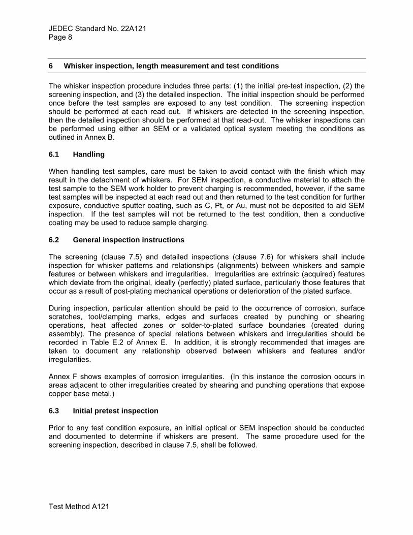
6 Whisker inspection, length measurement and test conditions The whisker inspection procedure includes three parts: (1) the initial pre-test inspection, (2) the screening inspection, and (3) the detailed inspection. The initial inspection should be performed once before the test samples are exposed to any test condition. The screening inspection should be performed at each read out. If whiskers are detected in the screening inspection, then the detailed inspection should be performed at that read-out. The whisker inspections can be performed using either an SEM or a validated optical system meeting the conditions as outlined in Annex B. 6.1 Handling When handling test samples, care must be taken to avoid contact with the finish which may result in the detachment of whiskers. For SEM inspection, a conductive material to attach the test sample to the SEM work holder to prevent charging is recommended, however, if the same test samples will be inspected at each read out and then returned to the test condition for further exposure, conductive sputter coating, such as C, Pt, or Au, must not be deposited to aid SEM inspection. If the test samples will not be returned to the test condition, then a conductive coating may be used to reduce sample charging. 6.2 General inspection instructions The screening (clause 7.5) and detailed inspections (clause 7.6) for whiskers shall include inspection for whisker patterns and relationships (alignments) between whiskers and sample features or between whiskers and irregularities. Irregularities are extrinsic (acquired) features which deviate from the original, ideally (perfectly) plated surface, particularly those features that occur as a result of post-plating mechanical operations or deterioration of the plated surface. During inspection, particular attention should be paid to the occurrence of corrosion, surface scratches, tool/clamping marks, edges and surfaces created by punching or shearing operations, heat affected zones or solder-to-plated surface boundaries (created during assembly). The presence of special relations between whiskers and irregularities should be recorded in Table E.2 of Annex E. In addition, it is strongly recommended that images are taken to document any relationship observed between whiskers and features and/or irregularities. Annex F shows examples of corrosion irregularities. (In this instance the corrosion occurs in areas adjacent to other irregularities created by shearing and punching operations that expose copper base metal.) 6.3 Initial pretest inspection Prior to any test condition exposure, an initial optical or SEM inspection should be conducted and documented to determine if whiskers are present. The same procedure used for the screening inspection, described in clause 7.5, shall be followed.
JEDEC Standard No. 22A121 Page 9
Test Method A121
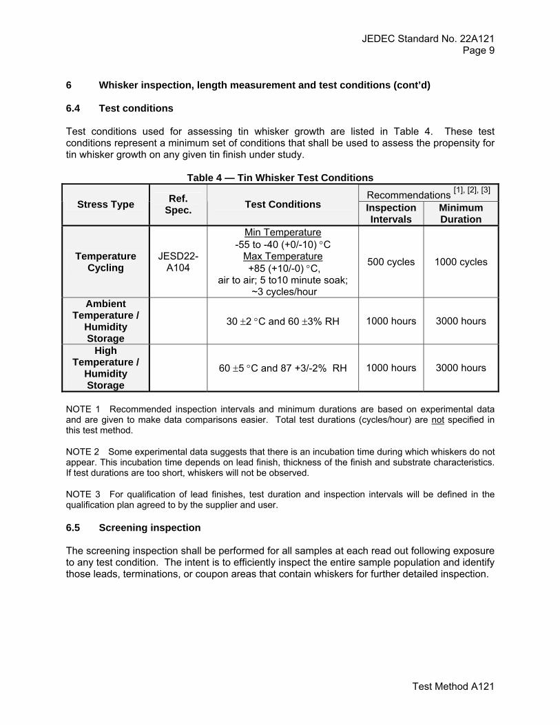
6 Whisker inspection, length measurement and test conditions (cont’d) 6.4 Test conditions Test conditions used for assessing tin whisker growth are listed in Table 4. These test conditions represent a minimum set of conditions that shall be used to assess the propensity for tin whisker growth on any given tin finish under study.
Table 4 — Tin Whisker Test Conditions Recommendations [1], [2], [3]
Stress Type Ref. Spec. Test Conditions Inspection
Intervals Minimum Duration
Temperature Cycling
JESD22-A104
Min Temperature -55 to -40 (+0/-10) °C
Max Temperature +85 (+10/-0) °C,
air to air; 5 to10 minute soak; ~3 cycles/hour
500 cycles 1000 cycles
Ambient Temperature /
Humidity Storage
30 ±2 °C and 60 ±3% RH 1000 hours 3000 hours
High Temperature /
Humidity Storage
60 ±5 °C and 87 +3/-2% RH 1000 hours 3000 hours
NOTE 1 Recommended inspection intervals and minimum durations are based on experimental data and are given to make data comparisons easier. Total test durations (cycles/hour) are not specified in this test method.
NOTE 2 Some experimental data suggests that there is an incubation time during which whiskers do not appear. This incubation time depends on lead finish, thickness of the finish and substrate characteristics. If test durations are too short, whiskers will not be observed.
NOTE 3 For qualification of lead finishes, test duration and inspection intervals will be defined in the qualification plan agreed to by the supplier and user. 6.5 Screening inspection The screening inspection shall be performed for all samples at each read out following exposure to any test condition. The intent is to efficiently inspect the entire sample population and identify those leads, terminations, or coupon areas that contain whiskers for further detailed inspection.

JEDEC Standard No. 22A121 Page 10
Test Method A121
6.5 Screening inspection (cont’d) 6.5.1 Components A minimum of 96 terminations from a minimum of 6 components must be inspected using either an optical system meeting the requirements of Annex B or an SEM. For components with large (≥0.85 mm2) terminations, refer to Table 1 to decrease the number of terminations to be inspected. If the screening inspection is performed with an optical system, a minimum magnification of 50X is required. For whisker verification, a higher magnification is recommended. If the screening inspection is performed with an SEM, a minimum magnification of 250X is required. If whiskers are not detected during the screening inspection, then a detailed inspection is not required at that read point. If whiskers are detected during the screening inspection, then a minimum of 18 areas that appear to have the longest tin whiskers shall be identified for detailed inspection. For most components, these 18 areas will consist of 3 terminations from each of the 6 test samples that were screened. However, for components with large plated terminations, multiple inspection areas may be identified on the same termination. Each inspection area should be at least 0.85 mm2. All of the 18 identified areas shall be evaluated in accordance with the detailed inspection procedure in clause 7.6. 6.5.2 Coupons A minimum of 3 coupons shall be inspected using either an optical system meeting the requirements of Annex B or an SEM. On each of these 3 coupons, a minimum area of 25 mm2 shall be screened, including at least two edges of at least 3 mm in total length. For small coupons, more coupons shall be screened, such that the total area screened is a minimum of 75 mm2. If the screening inspection is performed with an optical system, a minimum magnification of 50X is required. For whisker verification, a higher magnification is recommended. If the screening inspection is performed with an SEM, a minimum magnification of 250X is required. If whiskers are not detected during the screening inspection, then a detailed inspection is not required at that read point. If whiskers are detected during the screening inspection, then a minimum of three areas of 1.7 mm2 on each coupon that appear to have the longest tin whiskers shall be identified for detailed inspection. These three areas from each sample shall be evaluated following the detailed inspection procedure in clause 7.6. 6.6 Detailed inspection The detailed inspection shall be performed on terminations or areas identified in the screening inspection. If whiskers are not observed in the screening inspection then the detailed inspection is not required. For test samples that exhibit whiskers, 3 terminations or three areas per sample and a minimum of 6 components or 3 coupons shall be inspected. More test samples or inspection areas may be required if there are fewer than 3 leads or terminations per sample. A scanning electron microscope or a validated optical system (see Annex B) shall be used for the detailed inspection. For SEM inspections, a minimum magnification of 250X shall be used and for optical systems a minimum magnification of 50X shall be used. For the axial whisker length measurements themselves, a magnification higher or lower than that used for inspection may be required, such that the whisker being measured approximately fills the field of view at the selected magnification. Whisker length measurements should be made approximately perpendicular to the viewing direction for SEM and optical microscopy.

JEDEC Standard No. 22A121 Page 11
Test Method A121
6.6 Detailed inspection (cont’d) 6.6.1 Components with leads A minimum of 18 leads on a minimum of 6 components shall be inspected. The top, 2 sides, and bends of each identified lead shall be inspected as depicted in Figure 2. If leads are round then the surface that is the top ½ of the diameter should be inspected. Whiskers on the two sides may be easier to identify and measure if the component is mounted upside down in the “dead bug” position. For each inspected lead, the maximum whisker length shall be recorded as described in clause 7.7. The whisker density shall also be recorded for one lead identified as having the greatest number of whiskers following the protocol outlined in clause 7.7.3.2.
Figure 2 — A schematic diagram depicting a component lead and the top, 2 sides, and
bends of the lead that should be inspected.
6.6.2 Leadless components A minimum of 18 terminations on a minimum of 6 components shall be inspected. If there are fewer than three terminations on each component, then more than 6 components must be inspected to reach the requirement of 18 terminations. The top and 3 sides of each identified termination shall be inspected, as depicted in Figure 3. For each inspected termination, the maximum whisker length shall be recorded as described in clause 7.7. The whisker density shall also be recorded for one termination identified as having the greatest number of whiskers following the protocol outlined in clause 7.7.3.2.
Figure 3 — A schematic drawing depicting a leadless component and the top and 3 sides of the terminations that should be inspected.
Top
Bends
Side 1
Side 2

JEDEC Standard No. 22A121 Page 12
Test Method A121
6.6 Detailed inspection (cont’d) 6.6.3 Coupons A minimum of 9 areas on a minimum of 3 coupons shall be inspected. Each area shall be a minimum of 1.7 mm2 and should have been identified during the screening inspection. An example of inspection areas is depicted in Figure 4. For each inspected area, the maximum whisker length shall be recorded as described in clause 7.7. The whisker density shall also be recorded for one area identified as having the greatest number of whiskers following the protocol outlined in clause 7.7.3.2.
Figure 4. A schematic drawing depicting one possible coupon and three 1.7 mm2 areas identified for inspection. 6.7 Recording procedure (Refer to Tin Whisker Tests Standard Report Formats in Annex E.) 6.7.1 General information The factors listed in Annex E, Table E.1, are known or believed to influence whisker behavior. All applicable information should be provided. 6.7.2 Recording of screening inspection For components, the number of components screened per test condition and the number of leads or terminations screened per component must be recorded. In addition, the number of leads or terminations with whiskers identified must be recorded. (For example, 6 components and 96 leads were screened and 14 leads exhibited whiskers). For coupons, the number of coupons and the inspection area per coupon that were screened must be recorded.
Test Coupon
Inspection areas (1.7 mm2) identified in the screening
inspection

JEDEC Standard No. 22A121 Page 13
Test Method A121
6.7 Recording procedure (cont’d) 6.7.3 Recording of detailed inspection The number of leads, terminations, or inspection areas evaluated in the detailed inspection per test condition must be recorded. An example format for recording the information is shown in Annex E, Table E.2. For each lead, termination, or coupon area that is inspected during the detailed inspection, the maximum axial whisker length must be recorded. The whisker density shall also be recorded for the one lead, termination, or coupon area exhibiting the greatest number of whiskers. For qualification, refer to the appropriate document for requirements. 6.7.3.1 Total axial whisker length Record the maximum whisker length measured on each lead, termination, or coupon area during the detailed inspection. Axial whisker length is measured from the termination/electroplate surface to the whisker tip. For tin whiskers that bend and change directions, the total axial length may be estimated by adding all of the straight subdivisions of a whisker. In Figure 5, there are two examples that depict estimating the axial whisker length when the whisker is segmented.
Figure 5 — Two examples depicting the estimation of axial whisker length that is made by adding all of the straight subdivisions or segments of a whisker.
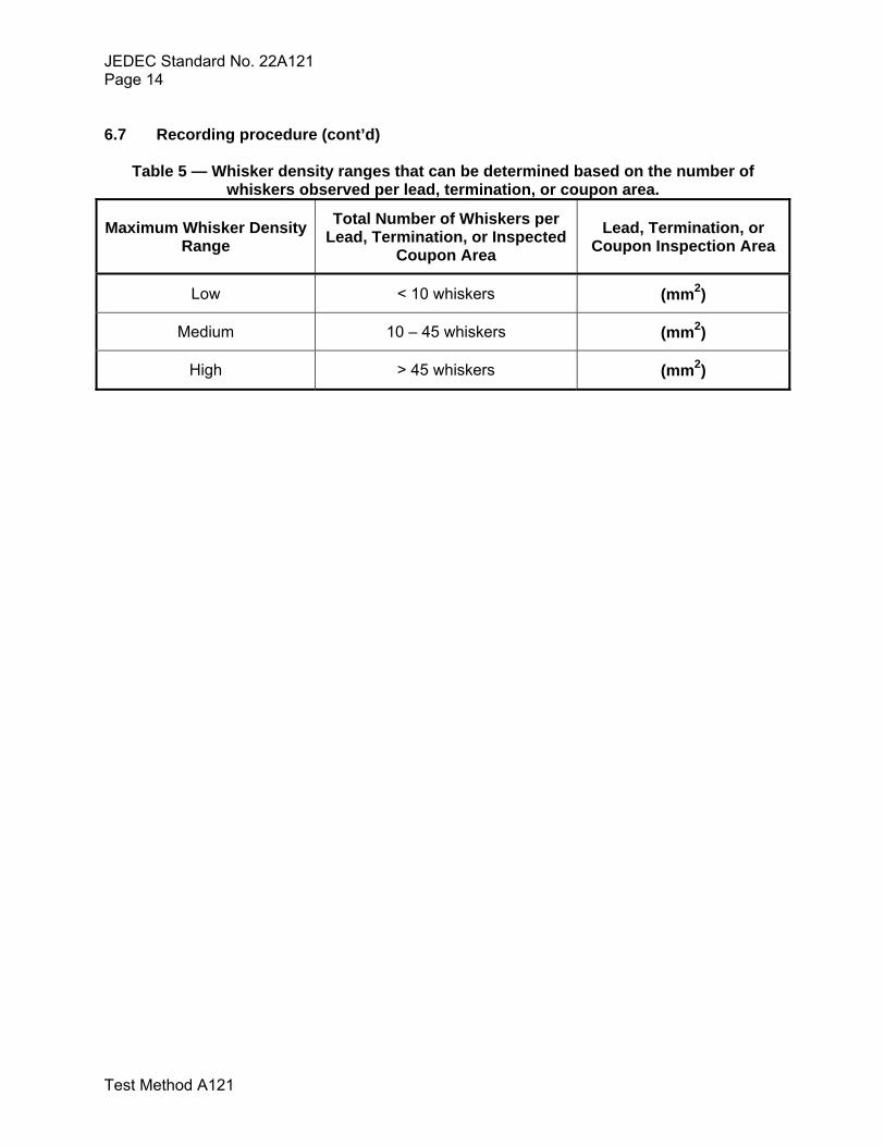
6.7.3.2 Whisker density range In the screening inspection, one lead or termination for components or one inspection area for coupons shall be identified as having approximately the greatest number of whiskers. For this one lead, termination, or coupon area, a whisker density range shall be determined using the following procedure. For most components, whiskers shall be counted on the entire top and sides of the lead or termination. The number of whiskers shall be recorded along with the amount of surface area that was inspected. Counting may be stopped when the total number of whiskers counted in the inspected surface area exceeds 45 whiskers. The total number of whiskers counted per lead, termination, or coupon area shall be used to classify the whisker density range, according to Table 5. NOTE: The whisker density range has not been correlated with whisker length. However, the chance of a whisker causing a failure may depend on the whisker density. Therefore, reporting of whisker density range may help to improve the understanding of how whisker density correlates (if at all) with maximum whisker length.
A
B
Whisker total axial
length = A + B
A
BC
D
Whisker total axial length
= A + B+ C+ D
JEDEC Standard No. 22A121 Page 14
Test Method A121
6.7 Recording procedure (cont’d)
Table 5 — Whisker density ranges that can be determined based on the number of whiskers observed per lead, termination, or coupon area.
Maximum Whisker Density Range
Total Number of Whiskers per Lead, Termination, or Inspected
Coupon Area Lead, Termination, or
Coupon Inspection Area
Low < 10 whiskers (mm2)
Medium 10 – 45 whiskers (mm2)
High > 45 whiskers (mm2)

JEDEC Standard No. 22A121 Page 15
Test Method A121
Annex A Process Flow for Sn-whisker Testing
Sample SelectionTable 1
Precondition Table 2
(Optional)
Screening Inspection (All selected samples per read-point)
Clause 7.5
Detailed Inspection (18 leads / areas identified with longest whiskers)
Clause 7.6
Whisker Density Measurement (One lead or area identified with greatest number of whiskers)
Table 5
Sn-whisker TestingTable 4
Testing Complete?
No
Stop
Yes
Initial Pretest InspectionClause 7.3
Record ResultsClause 7.7

JEDEC Standard No. 22A121 Page 16
Test Method A121
Annex B Validation of optical microscopy equipment Validation of the capability of optical equipment which is used for screening inspection and/or whisker length measurement is required. The capability of the optical inspection equipment and the associated optical process must be validated per clauses B.1, B.2, and B.3 using reference samples inspected and characterized by an SEM. This validation process ensures that the optical equipment and the attendant inspection process can detect whiskers and result in an accurate assessment of the whisker lengths and densities. The same optical equipment can be used for the two different tasks (screening inspection per clause 7.5 and detailed whisker measurements per clause 7.6). However, in this case the equipment must be validated independently per clauses B.1, B.2, and B.3. If the optical inspection equipment or the optical measurement equipment fails to meet the requirements in clauses B.1, B.2, or B.3, the optical system has failed the validation test for the relevant intended purpose. In this case the optical equipment, the fixturing, the lighting, magnification, and/or viewing angle may be adjusted and the validation procedure repeated for the new configuration. A system need only be re-validated if there is a change in the optical equipment or the inspection process. NOTE 1 “Optical equipment” is the composite of an optical viewing system, sample retention and manipulation fixtures and lighting. NOTE 2 As an inspection tool, stereomicroscopes have several advantages over binocular microscopes, and are required for the screening inspection process. One important advantage is in depth perception. Stereomicroscopes have two separate optical paths. This makes depth perception and three-dimensional viewing of an object possible. Stereomicroscopes also offer long working distances and relatively large fields of view. These attributes make them ideal for whisker inspection. B.1 Capability of whisker detection The capability of the optical system used for whisker screening inspection shall be verified by following the screening inspection protocols in clause 7. The usage of a stereomicroscope is required for the screening inspection process. A minimum whisker length of 10 microns must be detectable with the optical system used for inspection. To verify this capability, the SEM shall be used to identify ten terminations or coupon areas that have whiskers, preferably using samples containing whiskers 10 to 20 microns in length (see Note 1), and ten terminations or coupon areas without whiskers greater than 10 microns in length. The latter will be referred to as being “without whiskers.” The optical system shall then be used to correctly detect the ten terminations or coupon areas containing whiskers and the ten that do not have whiskers. The system passes if the following criterion is met:

JEDEC Standard No. 22A121 Page 17
Test Method A121
B.1 Capability of whisker detection (cont’d) 1) In all cases, the correct distinction is made between terminals or coupon areas with whiskers
from those without.
If whiskers of 10 to 20 microns are detected in the SEM but not with the optical microscope, then validation of the optical system for whisker detection capability has failed. The measurements taken to validate the optical system and the results of the validation process should be documented for reference.
NOTE 1 A sample with whiskers having lengths of 10 to 20 microns can frequently be created by performing 500 to 1000 thermal cycles, as defined in Table 4, on a matte-tin plating or finish. If needed, a sample with a low density of whiskers can frequently be created by performing an isothermal aging using matte-tin over Cu, as defined in Table 4, for 3000 to 4000 hrs. NOTE 2 Test samples identified as containing areas both with and “without” whiskers could, with time during storage, nucleate and grow new whiskers or continue to grow existing whiskers. Therefore, reference samples identified and characterized for whisker-detection capability should not be used at a later time for additional optical system validations unless all samples are once again re-characterized by SEM inspection, and found to still meet the test sample requirements intended for the detection-capability process. NOTE 3 Capturing a low magnification image of the region containing the measured whisker can be used as an aid for finding and identifying the exact whisker of interest. This can be done with either optical or SEM techniques. B.2 Capability of whisker length measurement The capability of the optical system to accurately measure whisker lengths shall be validated by comparison of optical measurements to those made with an SEM. This comparison shall be made on samples with whisker lengths ranging from 10 to 50 microns, see Note 1. The minimum number of whiskers measured in this validation shall be 30. The individual whiskers measured shall be the same for both systems so that direct comparisons of measured lengths can be made. The optical system passes if the following criterion is met: 1) For the same whisker, the maximum axial whisker length measured with the optical system
differs by less than 5 microns on average and by less than 10 microns for any particular whisker from the measurements taken in the SEM.
The measurements taken to validate the optical system and the results of the validation process should be documented for reference.
NOTE 1 A sample with whiskers having lengths of 10 to 50 microns can frequently be created by performing 1000 to 2000 thermal cycles, as defined in Table 4, on a matte-tin plating or finish. NOTE 2 Reference samples used for whisker length as well as density measurements could, with time during storage, nucleate and grow new whiskers or continue to grow existing whiskers. Therefore, reference samples identified and characterized for the whisker length/density capability should not be used at a later time for additional optical system validations unless all samples are once again re-characterized by SEM inspection.

JEDEC Standard No. 22A121 Page 18
Test Method A121
Annex B Validation of optical microscopy equipment (cont’d) B.3 Capability of whisker density measurement The capability of the optical system to accurately measure the density of whiskers shall be validated by comparison of optical measurements to those made with an SEM. This comparison shall be made on six separate samples with whiskers ranging from 10 to 50 microns in length; refer to Note 1 of clause B.2. Preferably, at least one sample will have a high density of whiskers and at least one sample will have a low density of whiskers, according to Table 5. The six samples can be six separate terminations on one electronic component, six separate terminations from multiple different electronic components, or can be six different areas on one or more coupons. The samples used for validating whisker density measurement capability can be the same as those used for the whisker length measurement capability, clause B.2. For each sample, the number of whiskers greater than 10 microns in length shall be measured with both systems within the same viewing area. The optical system passes if the following criterion is met: 1) The whisker density measured with the optical system is within 20% of that measured with
an SEM.
The measurements taken to validate the optical system and the results of the validation process should be documented for reference.

JEDEC Standard No. 22A121 Page 19
Test Method A121
Annex C Tin Whisker Images A collection of scanning electron microscope images are presented in the annex that exemplifies the appearance of tin whiskers.
Tin whisker filaments. Whisker with a consistent cross section.
Whisker initiating from a hillock. Branched tin whiskers on bright tin (rare).
Kinked whisker. Kinked whiskers growing from a nodule.

JEDEC Standard No. 22A121 Page 20
Test Method A121
Annex C Tin Whisker Images (cont’d)

JEDEC Standard No. 22A121 Page 21
Test Method A121
Tin whisker filament with striations. Tin whisker filament with striations.
Kinked whisker on odd-shaped eruptions. Tin whisker with rings.

JEDEC Standard No. 22A121 Page 22
Test Method A121
Annex D Non-Whisker Surface Formations A collection of images is presented, exemplifying formations that may occur on a tin plated surface that are not considered whiskers for the purpose of this test method. These surface formations include dendrites, hillocks, and flowers.
Dendrites are fern-like growths formed for example as a result of solidification. They
are not whiskers.
Hillocks may be precursors to whiskers in some cases, but are not considered whiskers
for the purpose of this test method.
Dendrites formed on a tin surface during plating. These are not tin whiskers.
“Flower” created on a tin plating exposed to the test condition of high-temperature humidity
storage and is most likely a result of a combination of surface contamination and
condensation.
JEDEC Standard No. 22A121 Page 23
Test Method A121
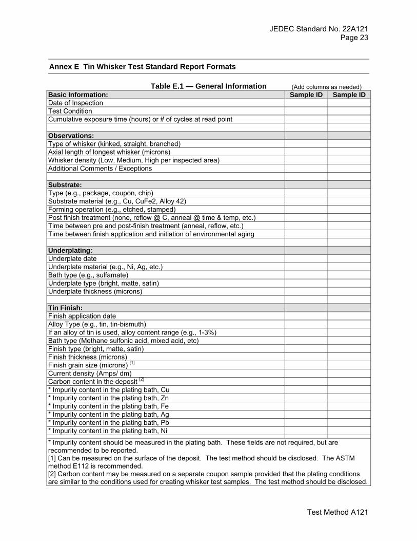
Annex E Tin Whisker Test Standard Report Formats
Table E.1 — General Information Basic Information: Sample ID Sample ID Date of Inspection Test Condition Cumulative exposure time (hours) or # of cycles at read point Observations: Type of whisker (kinked, straight, branched) Axial length of longest whisker (microns) Whisker density (Low, Medium, High per inspected area) Additional Comments / Exceptions Substrate: Type (e.g., package, coupon, chip) Substrate material (e.g., Cu, CuFe2, Alloy 42) Forming operation (e.g., etched, stamped) Post finish treatment (none, reflow @ C, anneal @ time & temp, etc.) Time between pre and post-finish treatment (anneal, reflow, etc.) Time between finish application and initiation of environmental aging Underplating: Underplate date Underplate material (e.g., Ni, Ag, etc.) Bath type (e.g., sulfamate) Underplate type (bright, matte, satin) Underplate thickness (microns) Tin Finish: Finish application date Alloy Type (e.g., tin, tin-bismuth) If an alloy of tin is used, alloy content range (e.g., 1-3%) Bath type (Methane sulfonic acid, mixed acid, etc) Finish type (bright, matte, satin) Finish thickness (microns) Finish grain size (microns) [1] Current density (Amps/ dm) Carbon content in the deposit [2] * Impurity content in the plating bath, Cu * Impurity content in the plating bath, Zn * Impurity content in the plating bath, Fe * Impurity content in the plating bath, Ag * Impurity content in the plating bath, Pb * Impurity content in the plating bath, Ni
* Impurity content should be measured in the plating bath. These fields are not required, but are recommended to be reported. [1] Can be measured on the surface of the deposit. The test method should be disclosed. The ASTM method E112 is recommended. [2] Carbon content may be measured on a separate coupon sample provided that the plating conditions are similar to the conditions used for creating whisker test samples. The test method should be disclosed.
(Add columns as needed)

JEDEC Standard No. 22A121 Page 24
Test Method A121
Annex E Tin Whisker Test Standard Report Formats (cont’d)
Table E.2 — Detailed Whisker Information
Screening observations: Sample Info Features
(e.g., corrosion, scratches, clamp
marks, etc.) Number of samples inspected Number of terminations or coupon areas inspected per sample Total number of terminations or coupon areas inspected Total area inspected Number of terminations or coupon areas with whiskers Detailed observations: Number of samples inspected Total number of terminations or coupon areas inspected Whisker density ((Low, Medium, High per inspected area)) Axial length of longest whisker (microns) – termination or coupon area 1 Axial length of longest whisker (microns) – termination or coupon area 2 Axial length of longest whisker (microns) – termination or coupon area 3 Axial length of longest whisker (microns) – termination or coupon area 4 Axial length of longest whisker (microns) – termination or coupon area 5 Axial length of longest whisker (microns) – termination or coupon area 6 Axial length of longest whisker (microns) – termination or coupon area 7 Axial length of longest whisker (microns) – termination or coupon area 8 Axial length of longest whisker (microns) – termination or coupon area 9 Axial length of longest whisker (microns) – termination or coupon area 10 Axial length of longest whisker (microns) – termination or coupon area 11 Axial length of longest whisker (microns) – termination or coupon area 12 Axial length of longest whisker (microns) – termination or coupon area 13 Axial length of longest whisker (microns) – termination or coupon area 14 Axial length of longest whisker (microns) – termination or coupon area 15 Axial length of longest whisker (microns) – termination or coupon area 16 Axial length of longest whisker (microns) – termination or coupon area 17 Axial length of longest whisker (microns) – termination or coupon area 18 Additional Comments: Additional Comments / Exceptions:

JEDEC Standard No. 22A121 Page 25
Test Method A121
Annex F Examples of Whiskers in Areas of Corrosion
Corroded Area
Whisker
Corroded Area
Whisker

JEDEC Standard No. 22A121 Page 26
Test Method A121
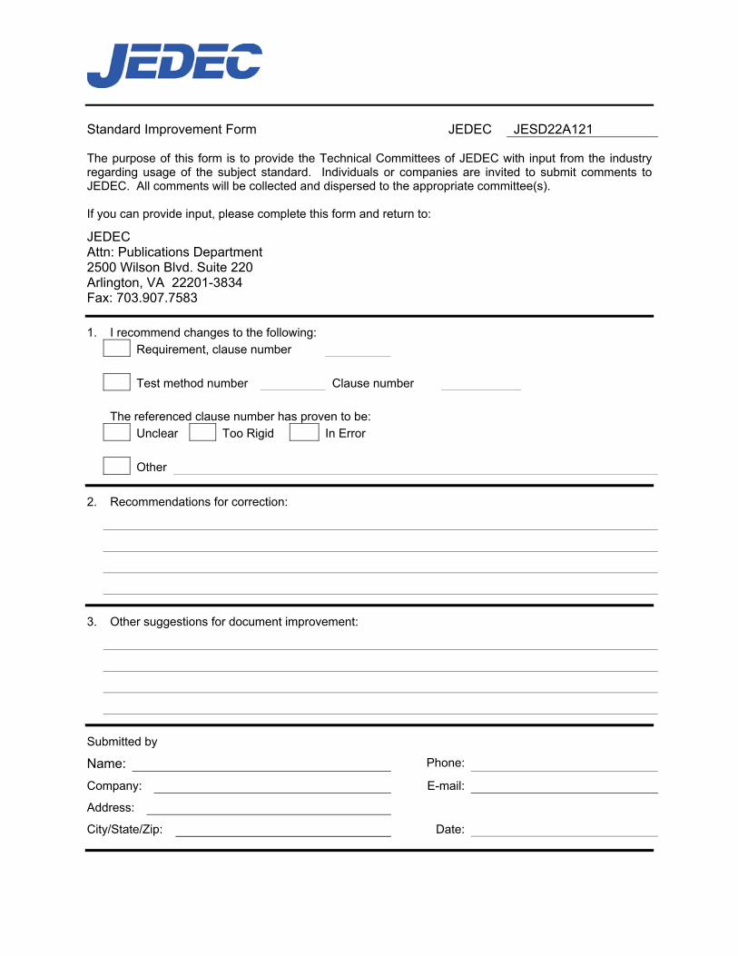
Standard Improvement Form JEDEC JESD22A121 The purpose of this form is to provide the Technical Committees of JEDEC with input from the industry regarding usage of the subject standard. Individuals or companies are invited to submit comments to JEDEC. All comments will be collected and dispersed to the appropriate committee(s). If you can provide input, please complete this form and return to:
JEDEC Attn: Publications Department 2500 Wilson Blvd. Suite 220 Arlington, VA 22201-3834 Fax: 703.907.7583
1. I recommend changes to the following: Requirement, clause number Test method number Clause number The referenced clause number has proven to be: Unclear Too Rigid In Error Other
2. Recommendations for correction:
3. Other suggestions for document improvement:
Submitted by
Name: Phone:
Company: E-mail:
Address:
City/State/Zip: Date: