Jazz up your Batch Projects - Control Global · ... Re-use, GAMP, Validation ... Project Life Cycle...
13
Copyright © 2006 WBF. All rights reserved. Page 1 Presented at the WBF North American Conference Atlanta, GA March 5-8, 2006 195 Wekiva Springs Road, Suite 200 Longwood, FL 32779-2552 +1.407.774.5764 Fax: +1.407.774.6751 E-mail: [email protected] www.wbf.org Jazz up your Batch projects Frede Vinther Senior Consultant Automation Solution Architects NNE A/S Gladsaxevej 372 DK-2860 Soeborg Denmark Telephone: +45 44447777 Fax: +45 44443777 [email protected] KEY WORDS Project execution, Time to Market, S88, S95, Human Factor, Communication, Object Oriented, Re-use, GAMP, Validation
Transcript of Jazz up your Batch Projects - Control Global · ... Re-use, GAMP, Validation ... Project Life Cycle...
Copyright © 2006 WBF. All rights reserved. Page 1
Presented at the WBF
North American Conference Atlanta, GA
March 5-8, 2006
195 Wekiva Springs Road, Suite 200Longwood, FL 32779-2552
+1.407.774.5764 Fax: +1.407.774.6751 E-mail: [email protected]
www.wbf.org
Jazz up your Batch projects
Frede Vinther
Senior Consultant Automation Solution Architects
NNE A/S Gladsaxevej 372
DK-2860 Soeborg Denmark
Telephone: +45 44447777 Fax: +45 44443777 [email protected]
KEY WORDS
Project execution, Time to Market, S88, S95, Human Factor, Communication, Object Oriented, Re-use, GAMP, Validation
Copyright © 2006 WBF. All rights reserved. Page 2
ABSTRACT
Enabling Pharmaceutical companies to make investment decisions as close as possible to the “Product on Market date” is essential for their business. This is not achieved only by having a “box” of standard software modules available, but the whole engineering and project execution process has to support this acceleration from concept to operation.
One of the large “time consumers” is Communication. Simplified there are the following 3 stakeholders in a Project: The Pharmaceutical- , the Engineering- and the Construction/Integrator Company. Here it is very important to focus on the contents of the communicated information, and especially what information on which level is important to each stakeholder.
Another “time consumer” is lack of functional breakdown of the actual process to be engineered and put in operation. This can be eased by applying standards as: S88 & S95 and by applying modular design and re-use, but this does not solve all functional issues.
This Paper specifically addresses these two aspects by demonstrating how essential a well executed Front End engineering and planning is to the Overall Project Efficiency. It does in detail describe the efficiency achieved by using tools supporting Object orientation combined with a set of standard functions.
PAPER
Introduction This paper describes an approach that will really Jazz up your Batch projects, especially if your industry is Pharmaceutical and your concerns are: Time to Market, Standardization & Validation .
The approach has a two fold focus - Human & Technology. First on the Human Factor, by addressing the main players involved in execution of a project, identification of their objectives and how to manage the differences between these. Second focus on the technology that will support managing the Human Factor.
Background What similarities do you see when you compare the Plants of a large Pharmaceutical Company?
What similarities do you see when you compare the Plants of a large Pharmaceutical Company that are used to produce the same product?
Answer: “Same Company Logo”
Copyright © 2006 WBF. All rights reserved. Page 3
The thing about Pharmaceutical plants is; they each and every have their own local history that also quite often involves an Ownership list. This is the main reason why one specific Pharmaceutical Company may have a number of plants producing the same or very similar product, but each and every plant is built according to its own local concepts and principles.
Now these concepts and principles do not only cover the Steel Structures, Machinery and Automation System, but also all the procedures (SOP), QA management of how to deploy the instructions for release of product for Sale, Personnel Training programs etc.
When looking back on this and comparing the result of all the projects needed to come to this point, and then compare this with building cars, it would probably look somehow like this:
OR
It is obvious that they are different They are both “handmade” according to specifications
They both fulfill the basic functionality required by a Car: Transportation, Shield from weather, Steering wheel, Brakes, Head Lights etc.
The same applies to the Pharmaceutical Plants. They are also “handmade” according to specifications, and each and every plant is almost “one of a kind”. This way of engineering and building Pharmaceutical Plants is not cost and time effective with respect to producing the Plant, nor is it cost and time effective to maintain a number of such Plants.
Planning a Project When preparing and planning for a new project, whether this is a plant-revamp, plant-extension or green-field, it is very important to approach the task with the previously described history of “handmade” plants in mind.
All involved players in the project will have their own “history” of building plants, concepts etc. Each player has specific areas of interest and focus. It is important to use this knowledge from “history”. In order to achieve efficient and fast project execution it is essential to focus on the project activities to be carried out to complete the project and build the plant, including the scope and content of each of these activities and deliverables.
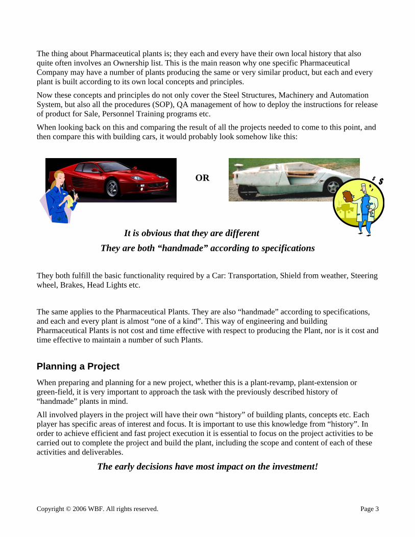
The early decisions have most impact on the investment!
Copyright © 2006 WBF. All rights reserved. Page 4
100
80
60
40
20
0
Financial Room for Manoeuvre
CD, BD
CommittedInvestment
Realized ProjectInvestmentFr
ont E
nd D
efin
ition
Proj
ect C
ompl
etio
n
Project Progress (time)
% of Total Project
Investment
100
80
60
40
20
0
Financial Room for Manoeuvre
CD, BD
CommittedInvestment
Realized ProjectInvestmentFr
ont E
nd D
efin
ition
Proj
ect C
ompl
etio
n
Project Progress (time)
% of Total Project
Investment
Financial Room for Manoeuvre
CD, BD
CommittedInvestment
Realized ProjectInvestmentFr
ont E
nd D
efin
ition
Proj
ect C
ompl
etio
n
Project Progress (time)
% of Total Project
Investment
Work done with Pharmaceutical clients yields the following points to be addressed in front end definition:
Copyright © 2006 WBF. All rights reserved. Page 5
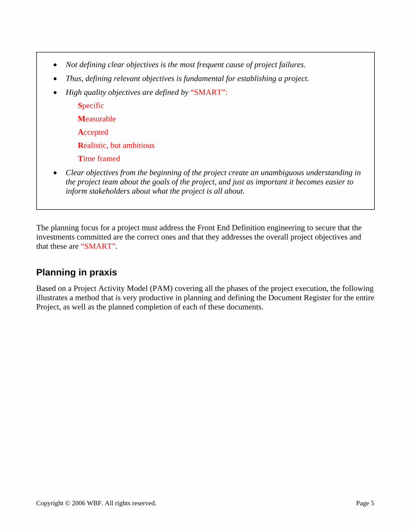
The planning focus for a project must address the Front End Definition engineering to secure that the investments committed are the correct ones and that they addresses the overall project objectives and that these are “SMART”.
Planning in praxis Based on a Project Activity Model (PAM) covering all the phases of the project execution, the following illustrates a method that is very productive in planning and defining the Document Register for the entire Project, as well as the planned completion of each of these documents.
• Not defining clear objectives is the most frequent cause of project failures.
• Thus, defining relevant objectives is fundamental for establishing a project.
• High quality objectives are defined by “SMART”:
Specific
Measurable
Accepted
Realistic, but ambitious
Time framed
• Clear objectives from the beginning of the project create an unambiguous understanding in the project team about the goals of the project, and just as important it becomes easier to inform stakeholders about what the project is all about.
Copyright © 2006 WBF. All rights reserved. Page 6
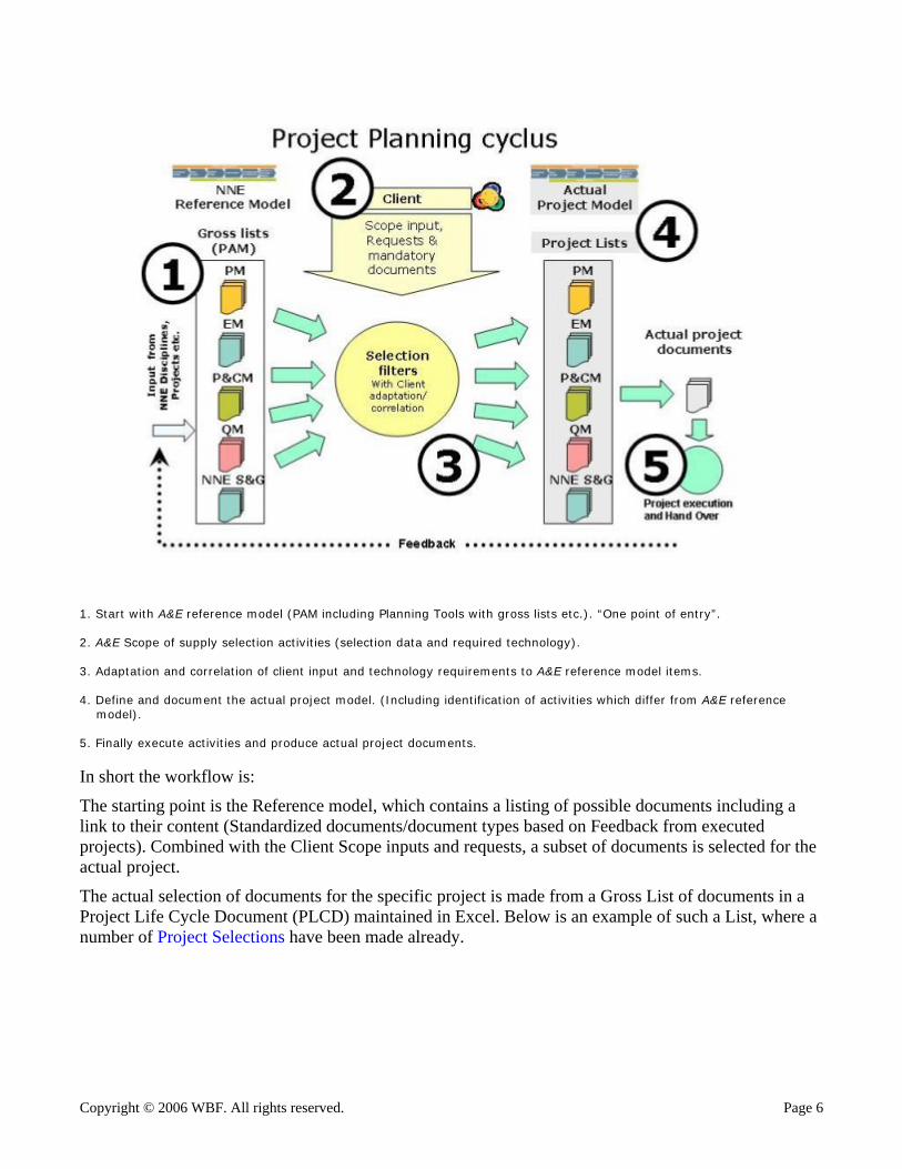
1. Start with A&E reference model (PAM including Planning Tools with gross lists etc.). “One point of entry”. 2. A&E Scope of supply selection activities (selection data and required technology). 3. Adaptation and correlation of client input and technology requirements to A&E reference model items. 4. Define and document the actual project model. (Including identification of activities which differ from A&E reference model). 5. Finally execute activities and produce actual project documents.
In short the workflow is:
The starting point is the Reference model, which contains a listing of possible documents including a link to their content (Standardized documents/document types based on Feedback from executed projects). Combined with the Client Scope inputs and requests, a subset of documents is selected for the actual project.
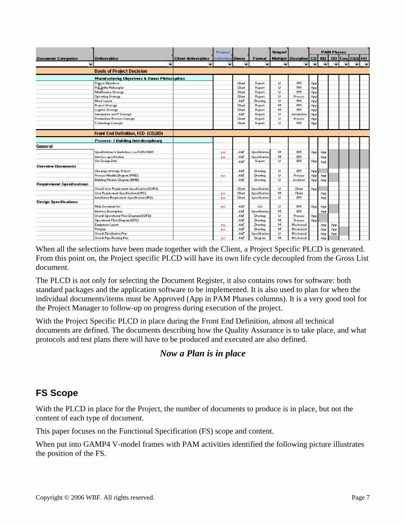
The actual selection of documents for the specific project is made from a Gross List of documents in a Project Life Cycle Document (PLCD) maintained in Excel. Below is an example of such a List, where a number of Project Selections have been made already.
Copyright © 2006 WBF. All rights reserved. Page 7
When all the selections have been made together with the Client, a Project Specific PLCD is generated. From this point on, the Project specific PLCD will have its own life cycle decoupled from the Gross List document.
The PLCD is not only for selecting the Document Register, it also contains rows for software: both standard packages and the application software to be implemented. It is also used to plan for when the individual documents/items must be Approved (App in PAM Phases columns). It is a very good tool for the Project Manager to follow-up on progress during execution of the project.
With the Project Specific PLCD in place during the Front End Definition, almost all technical documents are defined. The documents describing how the Quality Assurance is to take place, and what protocols and test plans there will have to be produced and executed are also defined.
Now a Plan is in place
FS Scope With the PLCD in place for the Project, the number of documents to produce is in place, but not the content of each type of document.
This paper focuses on the Functional Specification (FS) scope and content.
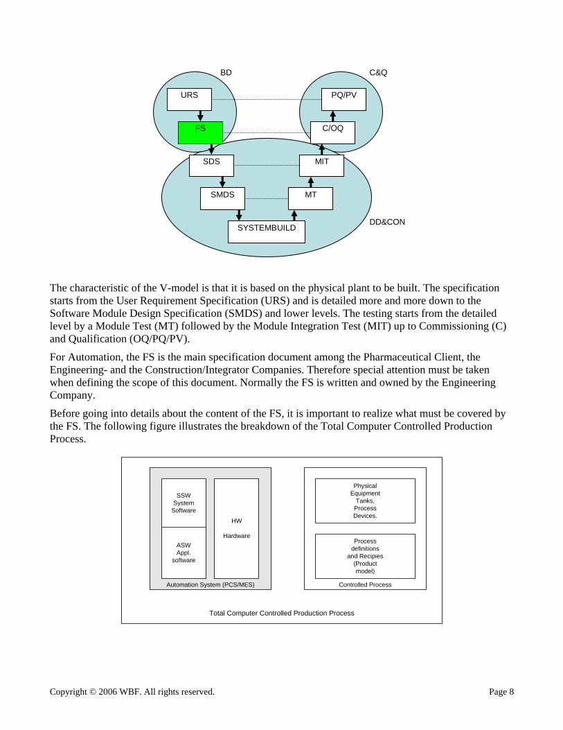
When put into GAMP4 V-model frames with PAM activities identified the following picture illustrates the position of the FS.
Copyright © 2006 WBF. All rights reserved. Page 8
URS
FS
SDS
SMDS
SYSTEMBUILD
MT
MIT
C/OQ
PQ/PV
BD
DD&CON
C&Q
The characteristic of the V-model is that it is based on the physical plant to be built. The specification starts from the User Requirement Specification (URS) and is detailed more and more down to the Software Module Design Specification (SMDS) and lower levels. The testing starts from the detailed level by a Module Test (MT) followed by the Module Integration Test (MIT) up to Commissioning (C) and Qualification (OQ/PQ/PV).
For Automation, the FS is the main specification document among the Pharmaceutical Client, the Engineering- and the Construction/Integrator Companies. Therefore special attention must be taken when defining the scope of this document. Normally the FS is written and owned by the Engineering Company.
Before going into details about the content of the FS, it is important to realize what must be covered by the FS. The following figure illustrates the breakdown of the Total Computer Controlled Production Process.
Total Computer Controlled Production Process
Automation System (PCS/MES) Controlled Process
HW
Hardware
PhysicalEquipment
Tanks,ProcessDevices.
Processdefinitions
and Recipies(Productmodel)
ASWAppl.
software
SSWSystem
Software
Copyright © 2006 WBF. All rights reserved. Page 9
When making the FS, it must be grouped accordingly to this breakdown. In other words, there must be a specific FS for the “Automation System”; covering items that are generic and plant wide in nature as: Network, PCs, Operator panels, Backup/restore and other overall system functions as: Electronic Signatures, Batch control capabilities, Standard System software, Standardized Application software, etc.
There must also be specific FS for the “Controlled Process”; covering the equipment structuring and breakdown into Units and Equipment Modules, the process functions of the Units and Equipment Modules and the functions to run the process e.g. the Recipe Procedures etc.
It is also important in the URS to identify the requirements that are NOT related to the Production Process itself, but are related solely to the scope of delivery of equipment (e.g. count of free IO points for expansion, specific required field instruments etc.). These are NOT to be validated at all, but only to be verified by the Client to secure the actual delivery. Normally these requirements are covered by the FS for the “Automation System”.
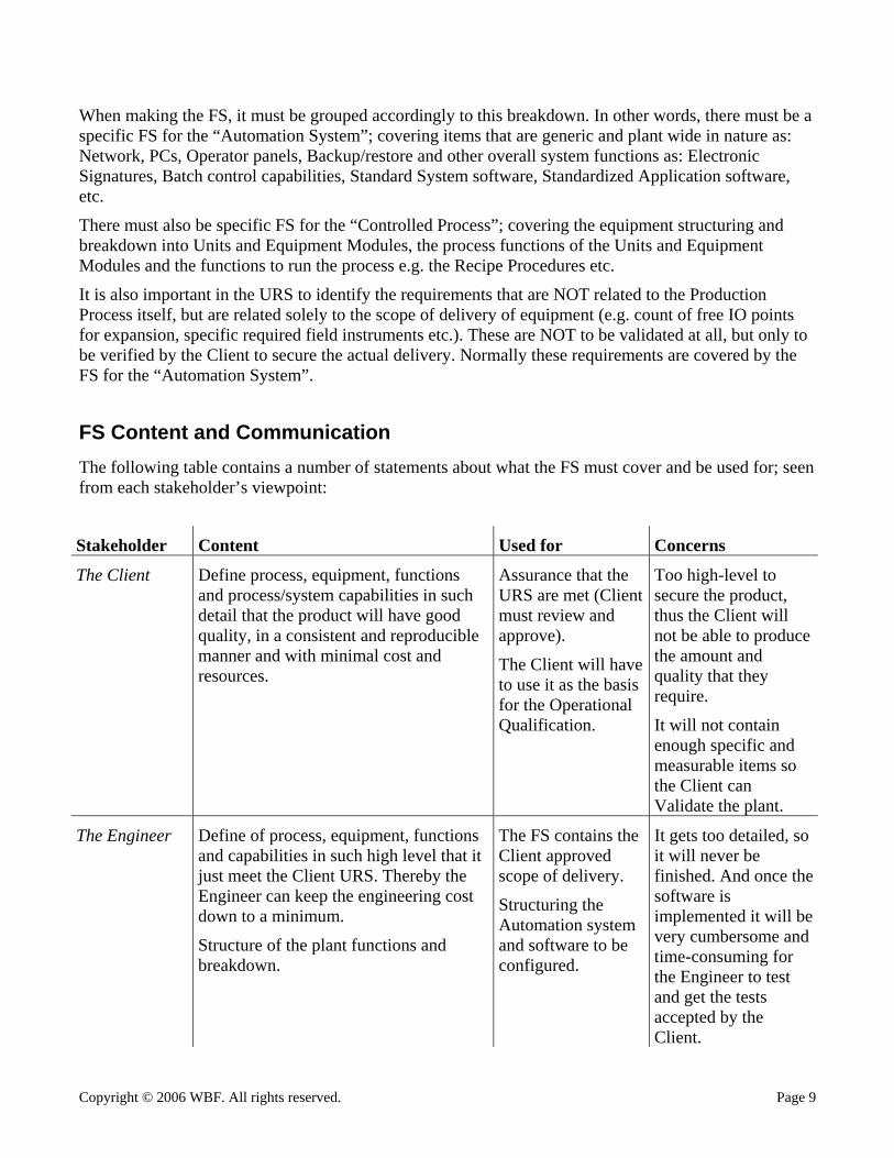
FS Content and Communication The following table contains a number of statements about what the FS must cover and be used for; seen from each stakeholder’s viewpoint:
Stakeholder Content Used for Concerns
The Client Define process, equipment, functions and process/system capabilities in such detail that the product will have good quality, in a consistent and reproducible manner and with minimal cost and resources.
Assurance that the URS are met (Client must review and approve).
The Client will have to use it as the basis for the Operational Qualification.
Too high-level to secure the product, thus the Client will not be able to produce the amount and quality that they require.
It will not contain enough specific and measurable items so the Client can Validate the plant.
The Engineer Define of process, equipment, functions and capabilities in such high level that it just meet the Client URS. Thereby the Engineer can keep the engineering cost down to a minimum.
Structure of the plant functions and breakdown.
The FS contains the Client approved scope of delivery.
Structuring the Automation system and software to be configured.
It gets too detailed, so it will never be finished. And once the software is implemented it will be very cumbersome and time-consuming for the Engineer to test and get the tests accepted by the Client.
Copyright © 2006 WBF. All rights reserved. Page 10
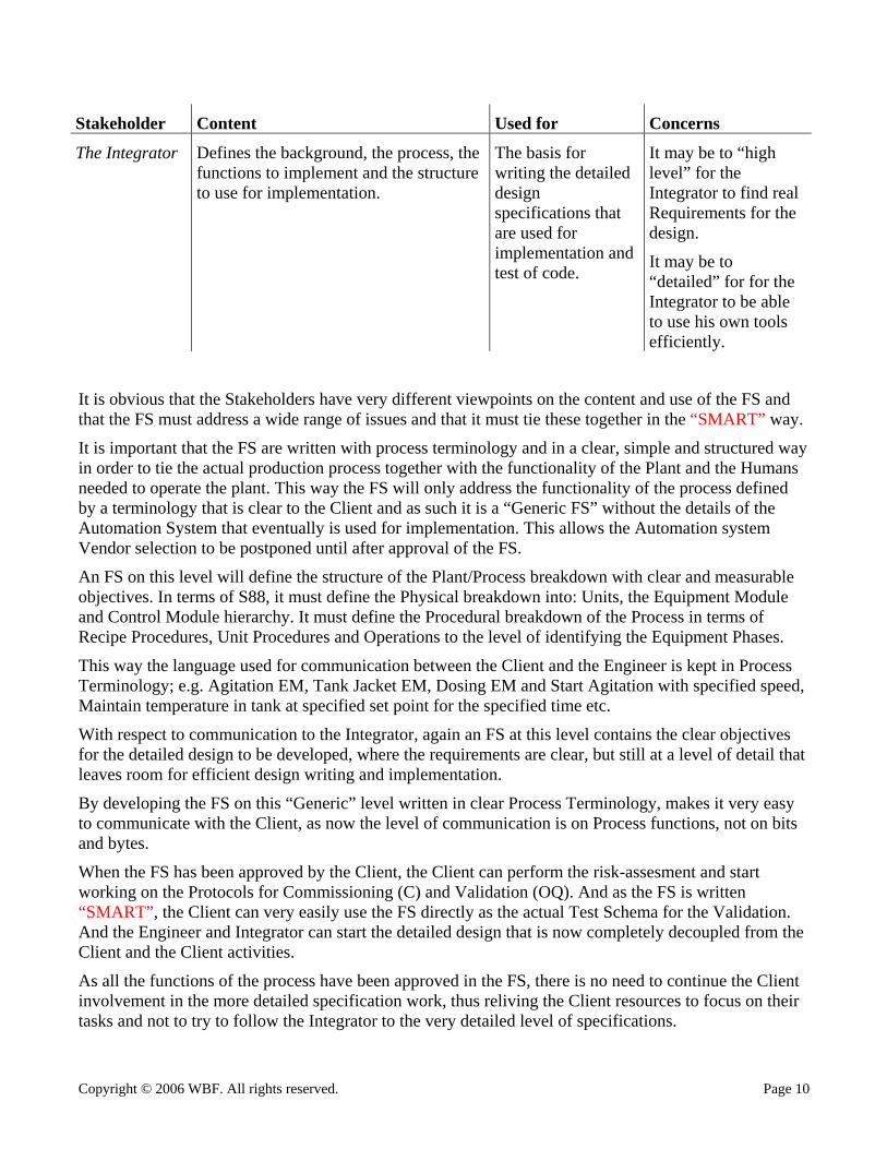
Stakeholder Content Used for Concerns
The Integrator Defines the background, the process, the functions to implement and the structure to use for implementation.
The basis for writing the detailed design specifications that are used for implementation and test of code.
It may be to “high level” for the Integrator to find real Requirements for the design.
It may be to “detailed” for for the Integrator to be able to use his own tools efficiently.
It is obvious that the Stakeholders have very different viewpoints on the content and use of the FS and that the FS must address a wide range of issues and that it must tie these together in the “SMART” way.
It is important that the FS are written with process terminology and in a clear, simple and structured way in order to tie the actual production process together with the functionality of the Plant and the Humans needed to operate the plant. This way the FS will only address the functionality of the process defined by a terminology that is clear to the Client and as such it is a “Generic FS” without the details of the Automation System that eventually is used for implementation. This allows the Automation system Vendor selection to be postponed until after approval of the FS.
An FS on this level will define the structure of the Plant/Process breakdown with clear and measurable objectives. In terms of S88, it must define the Physical breakdown into: Units, the Equipment Module and Control Module hierarchy. It must define the Procedural breakdown of the Process in terms of Recipe Procedures, Unit Procedures and Operations to the level of identifying the Equipment Phases.
This way the language used for communication between the Client and the Engineer is kept in Process Terminology; e.g. Agitation EM, Tank Jacket EM, Dosing EM and Start Agitation with specified speed, Maintain temperature in tank at specified set point for the specified time etc.
With respect to communication to the Integrator, again an FS at this level contains the clear objectives for the detailed design to be developed, where the requirements are clear, but still at a level of detail that leaves room for efficient design writing and implementation.
By developing the FS on this “Generic” level written in clear Process Terminology, makes it very easy to communicate with the Client, as now the level of communication is on Process functions, not on bits and bytes.
When the FS has been approved by the Client, the Client can perform the risk-assesment and start working on the Protocols for Commissioning (C) and Validation (OQ). And as the FS is written “SMART”, the Client can very easily use the FS directly as the actual Test Schema for the Validation. And the Engineer and Integrator can start the detailed design that is now completely decoupled from the Client and the Client activities.
As all the functions of the process have been approved in the FS, there is no need to continue the Client involvement in the more detailed specification work, thus reliving the Client resources to focus on their tasks and not to try to follow the Integrator to the very detailed level of specifications.
Copyright © 2006 WBF. All rights reserved. Page 11
It is very important that the FS at this stage is under strict change management control, as any changes in this will both influence the Integrators detailed design as well as the Client C&Q activities, and as such is one of the main tools to manage the scope of the Automation Project.
It is essential that the content of the FS is kept on this process functional level and not being blurred with Automation System specific details as bits and bytes, that if so eventually will end up in the Client C&Q protocols, and thus will have to be verified at a too high quality level with the additional cost and risk of project delays.
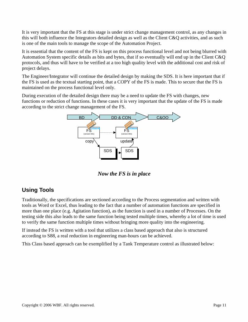
The Engineer/Integrator will continue the detailed design by making the SDS. It is here important that if the FS is used as the textual starting point, that a COPY of the FS is made. This to secure that the FS is maintained on the process functional level only.
During execution of the detailed design there may be a need to update the FS with changes, new functions or reduction of functions. In these cases it is very important that the update of the FS is made according to the strict change management of the FS.
SDS
FS (version 001)
SDS
BD DD & CON C&OQ
copy
FS (version 00n)
SDS SDS
update
Now the FS is in place
Using Tools Traditionally, the specifications are sectioned according to the Process segmentation and written with tools as Word or Excel, thus leading to the fact that a number of automation functions are specified in more than one place (e.g. Agitation function), as the function is used in a number of Processes. On the testing side this also leads to the same function being tested multiple times, whereby a lot of time is used to verify the same function multiple times without bringing more quality into the engineering.
If instead the FS is written with a tool that utilizes a class based approach that also is structured according to S88, a real reduction in engineering man-hours can be achieved.
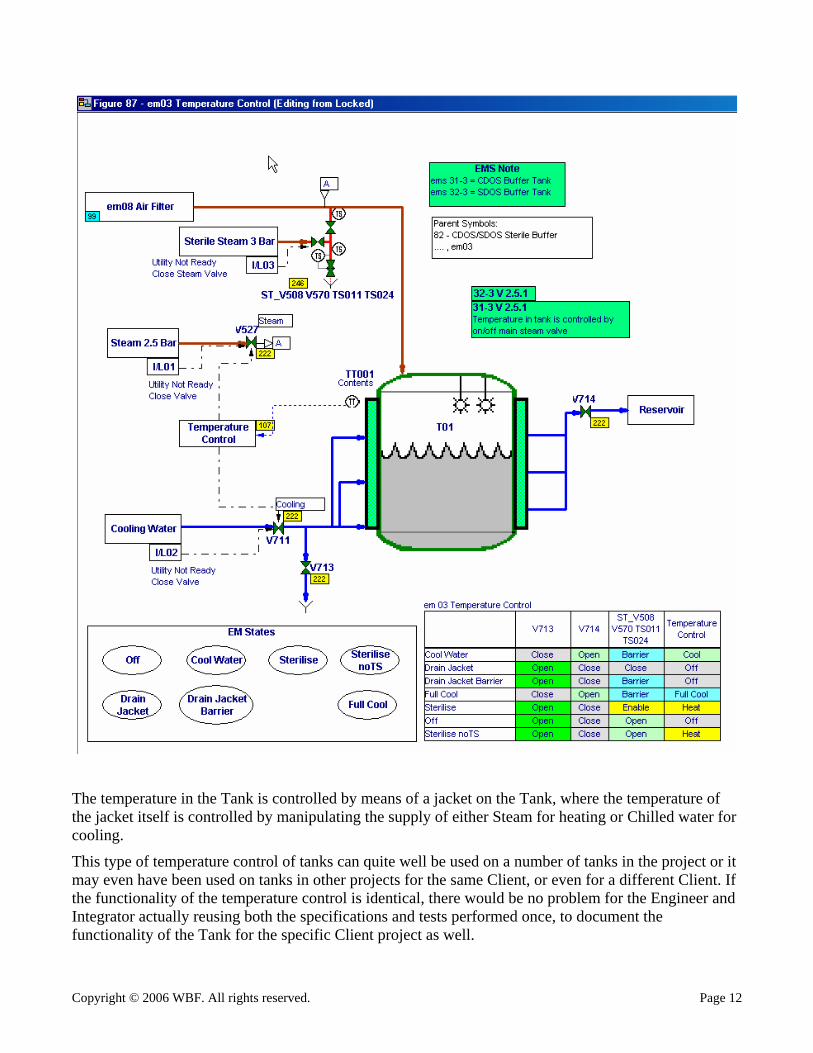
This Class based approach can be exemplified by a Tank Temperature control as illustrated below:
Copyright © 2006 WBF. All rights reserved. Page 12
The temperature in the Tank is controlled by means of a jacket on the Tank, where the temperature of the jacket itself is controlled by manipulating the supply of either Steam for heating or Chilled water for cooling.
This type of temperature control of tanks can quite well be used on a number of tanks in the project or it may even have been used on tanks in other projects for the same Client, or even for a different Client. If the functionality of the temperature control is identical, there would be no problem for the Engineer and Integrator actually reusing both the specifications and tests performed once, to document the functionality of the Tank for the specific Client project as well.
Copyright © 2006 WBF. All rights reserved. Page 13
The whole idea is that if there is a function that is used more than one time, then it shall only be designed once in one specification, is shall only be coded once and functionally tested once.
By applying this Class based approach covering specification, software & test, the Supplier can perform the engineering for the specific Client project. This approach is exactly like the approach for basic control modules for Valves, Motors, PID loops etc. When the Integrator uses the control modules supplied from the Automation system Vendor, no additional specification writing or module testing is necessary, as this has already been performed by the Automation system Vendor. In theory there is no upper limit to the extent of such a Class module, but in praxis the highest level of Class in this context will be the S88 Process Unit.
The tool described above and the benefits achieved by using it in Fast Track projects has been described and presented at the World Batch Forum in 2002, “Analyse, design, develop and validate-Fast” by Andrew Knott & Francis Lovering.
Now the “SMART”FS is in place
Conclusions The approach of Good and well structured Front End Definition planning, Making the FS “Generic” and “SMART” and to combine this with using a Class-based specification tool provides the following benefits:
Early identification and naming of >85% of all Technical documentation
Well defined scope and resource planning
Easy communication with Stakeholders
Clear Objectives; Specific, Measurable, Accepted, Realistic, Time framed
Re-use ability within project and with past and future projects
Functions only validated once
Reduced: Cost, Time scale and Risk