Jaypee Gold Standard Mini Atlas Series Orthodontics · Preface The Mini Atlas in Orthodontics, is a...
158
Transcript of Jaypee Gold Standard Mini Atlas Series Orthodontics · Preface The Mini Atlas in Orthodontics, is a...


Jaypee Gold Standard Mini Atlas Series®
Orthodontics

Jaypee Gold Standard Mini Atlas Series®
Orthodontics
JAYPEE BROTHERS MEDICAL PUBLISHERS (P) LTDNew Delhi • Ahmedabad • Bengaluru • Chennai • Hyderabad
Kochi • Kolkata • Lucknow • Mumbai • Nagpur
®
Gurkeerat SinghBDS MDS (Ortho.) M Orth (Intercollegiate)
Professor and Head, Department ofOrthodontics and Dentofacial Orthopedics
Sudha Rustagi College of Dental Sciences and ResearchFaridabad, Haryana, India
Published byJitendar P VijJaypee Brothers Medical Publishers (P) LtdCorporate Office4838/24 Ansari Road, Daryaganj, New Delhi - 110002, India, Phone: +91-11-43574357Registered OfficeB-3 EMCA House, 23/23B Ansari Road, Daryaganj, New Delhi - 110 002, IndiaPhones: +91-11-23272143, +91-11-23272703, +91-11-23282021+91-11-23245672, Rel: +91-11-32558559, Fax: +91-11-23276490, +91-11-23245683e-mail: [email protected], Website: www.jaypeebrothers.comBranches 2/B, Akruti Society, Jodhpur Gam Road Satellite
Ahmedabad 380 015, Phones: +91-79-26926233, Rel: +91-79-32988717Fax: +91-79-26927094 e-mail: [email protected]
202 Batavia Chambers, 8 Kumara Krupa Road, Kumara Park EastBengaluru 560 001, Phones: +91-80-22285971, +91-80-22382956, 91-80-22372664Rel: +91-80-32714073, Fax: +91-80-22281761 e-mail: [email protected]
282 IIIrd Floor, Khaleel Shirazi Estate, Fountain Plaza, Pantheon RoadChennai 600 008, Phones: +91-44-28193265, +91-44-28194897, Rel: +91-44-32972089Fax: +91-44-28193231 e-mail: [email protected]
4-2-1067/1-3, 1st Floor, Balaji Building, Ramkote Cross Road,Hyderabad 500 095, Phones: +91-40-66610020, +91-40-24758498Rel:+91-40-32940929, Fax:+91-40-24758499 e-mail: [email protected]
No. 41/3098, B & B1, Kuruvi Building, St. Vincent RoadKochi 682 018, Kerala, Phones: +91-484-4036109, +91-484-2395739+91-484-2395740 e-mail: [email protected]
1-A Indian Mirror Street, Wellington SquareKolkata 700 013, Phones: +91-33-22651926, +91-33-22276404, +91-33-22276415,Rel: +91-33-32901926, Fax: +91-33-22656075 e-mail: [email protected]
Lekhraj Market III, B-2, Sector-4, Faizabad Road, Indira NagarLucknow 226 016, Phones: +91-522-3040553, +91-522-3040554 e-mail: [email protected]
106 Amit Industrial Estate, 61 Dr SS Rao Road, Near MGM Hospital, ParelMumbai 400 012, Phones: +91-22-24124863, +91-22-24104532,Rel: +91-22-32926896, Fax: +91-22-24160828 e-mail: [email protected]
“KAMALPUSHPA” 38, Reshimbag, Opp. Mohota Science College, Umred RoadNagpur 440 009 (MS), Phone: Rel: +91-712-3245220, Fax: +91-712-2704275e-mail: [email protected]
USA Office1745, Pheasant Run Drive, Maryland Heights (Missouri), MO 63043, USA, Ph: 001-636-6279734e-mail: [email protected], [email protected]
Jaypee Gold Standard Mini Atlas Series®: Orthodontics© 2009, Jaypee Brothers Medical Publishers
All rights reserved. No part of this publication and photo CD ROM should be reproduced, stored in a retrievalsystem, or transmitted in any form or by any means: electronic, mechanical, photocopying, recording, orotherwise, without the prior written permission of the author and the publisher.This book has been published in good faith that the material provided by author is original. Every effort ismade to ensure accuracy of material, but the publisher, printer and author will not be held responsible for anyinadvertent error(s). In case of any dispute, all legal matters are to be settled under Delhi jurisdiction only.
First Edition: 2009ISBN 978-81-8448-464-9Typeset at JPBMP typesetting unitPrinted at Ajanta Offset & Packagins Ltd., New Delhi

Dedicated tothe past, present and future
Orthodontic Patients


Preface
The Mini Atlas in Orthodontics, is a small effort tospread the knowledge of orthodontics. An atlas, with itsinherent concept of illustrations and photographs providesa visual impact that is required to understand the variousclinical situations.
This atlas will not only be an aid for the clinicians butshall also serve as a visual guide to educate the patients.Such visual aids provide a reason for the patients to thinkand at times correlate the photographs with their ownconditions—thus seeking treatment.
Basic knowledge is provided and has been furthersimplified with the aid of photographs depicting individualsituations for easy understanding. Orthodontics is a vastscience today and the mini atlas is only a small, yet basicpart of this science.
Gurkeerat Singh

Acknowledgements
No publication is produced just by the hard work andlabor of the author or the editor. This atlas has beencompiled because of my dear patients, who have beengracious enough to tolerate my photographic skills andmy co-clinicians—Dr Abhay Lamba, Dr Rajesh Ahal,Dr Vishal Singh and Dr Pankaj Dutta who havecontributed to produce not just great smiles for thepatients but picture perfect results which we are proud toshow-case here.
Dr Ankur Kaul and Dr Aditya Chhibber are not justmy colleagues in the department at the college but mybest critics. It is their untiring effort that motivates me togather more relevant and better quality photographs forthis atlas. Last but not the least—the members of theJaypee team keep any author on his / her toes in orderto produce results and I am no exception.


Contents
1. Orthodontics: Introduction and Definition............ 12. The Scope and Aims ............................................ 53. Treatment Options ............................................. 254. Normal Occlusion .............................................. 515. Classification of Malocclusion ............................. 616. Common Etiological Factors .............................. 897. Treatment Results ............................................ 126
Index ............................................................... 147


2 ORTHODONTICS
For a layman, orthodontics is that branch of dentistry thatdeals with aligning of teeth using braces, basically anesthetic treatment associated with young children.However, being the first specialty branch of dentistry withover 100 years of existence, this is an over simplificationof a rather complex science.
In 1911, Noyes defined orthodontics as—“the studyof the relation of the teeth to the development of theface, and the correction of arrested and perverteddevelopment.”
In 1922, the British Society of Orthodontists proposedthat—“Orthodontics includes the study of growth anddevelopment of the jaws and face particularly, and thebody generally, as influencing the position of the teeth;the study of action and reaction of internal and externalinfluences on the development, and the prevention andcorrection of arrested and perverted development.”
The American Board of Orthodontics (ABO) and(AAO)—“Orthodontics is that specific area of dentalpractice that has as its responsibility the study andsupervision of the growth and development of the dentitionand its related anatomical structures from birth to dentalmaturity, including all preventive and corrective proceduresof dental irregularities requiring the repositioning of teethby functional or mechanical means to establish normalocclusion and pleasing facial contours.”

3ORTHODONTICS: INTRODUCTION AND DEFINITION
With the advent of 21st century, our knowledge of lifesciences has increased tremendously. Today, we canpredict the extent of possible growth in individual casesand even mould the growing child’s face.
Along with this, the extensive advances in materialscience has brought about better acceptance of ourtreatment plans by children and adults alike. With theadvent of esthetic (tooth colored) appliances (Fig. 1.1)and lingual appliances (Fig. 1.2) (invisible braces or bracesthat are actually put towards the tongue) the acceptanceof orthodontic treatment has increased many fold.
Fig. 1.1: Tooth colored esthetic brackets (Lower arch)

4 ORTHODONTICS
Fig. 1.2: The lingual appliance, brackets/braces placedtowards the tongue (Upper arch)
Advances in surgical procedures have added a wholenew dimension of orthognathic surgery to the field oforthodontics. Now if tooth movement is beyond thepreview of orthodontics alone, orthognathic surgery canaid in aligning the jaws per se. Today orthodonticcorrection can be brought about at practically any age aslong as the supporting structures are healthy and thepatient motivated.


6 ORTHODONTICS
Orthodontic treatment is aimed at moving teeth, alteringjaw bones and the soft tissue envelope.
Jackson had summarized the aims of orthodontictreatment as:• Functional efficiency.• Structural balance.• Esthetic harmony.
These three are now famous as the Jackson’s triad.
7THE SCOPE AND AIMS
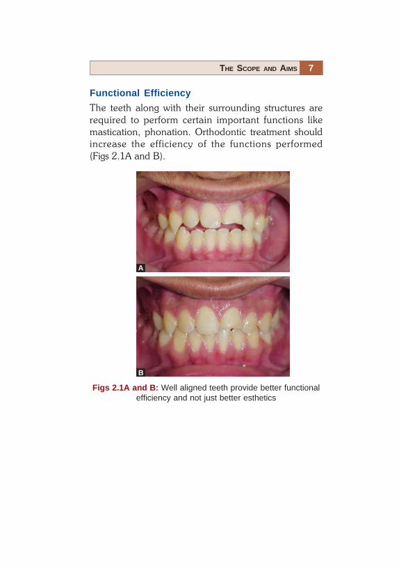
Functional Efficiency
The teeth along with their surrounding structures arerequired to perform certain important functions likemastication, phonation. Orthodontic treatment shouldincrease the efficiency of the functions performed(Figs 2.1A and B).
Figs 2.1A and B: Well aligned teeth provide better functionalefficiency and not just better esthetics
A
B

8 ORTHODONTICS
Structural Balance
The treatment should maintain a balance between thesestructures, and the correction of one should not bedetrimental to the health of another (Figs 2.2A to 2.3B).
Figs 2.2A and B: A more balanced profile representing a betterrelationship of the basal bones and increased chewing efficiencyof the teeth
BA

9THE SCOPE AND AIMS
Figs 2.3A and B: Esthetic harmony achieved followingorthodontic treatment combined with orthognathic surgery(Orthognathic surgery, Courtesy: Dr Vishal Singh)
BA

10 ORTHODONTICS
Esthetic Harmony
The orthodontic treatment should increase the overallesthetic appeal of the individual. This might just requirethe alignment of certain teeth or the forward movementof the complete jaw including its basal bone. The aim is toget results which gel with the patient’s personality andmake him /her look more esthetic (Figa 2.4A and B).
Figs 2.4A and B: Better esthetic harmony achieved followingorthodontic treatment along with the extraction of all first pre-molars
A B
11THE SCOPE AND AIMS
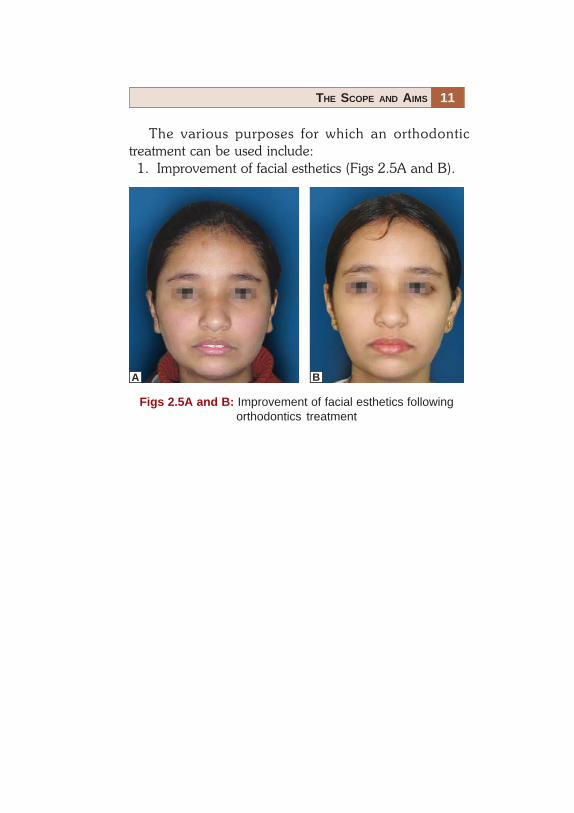
Figs 2.5A and B: Improvement of facial esthetics followingorthodontics treatment
The various purposes for which an orthodontictreatment can be used include:
1. Improvement of facial esthetics (Figs 2.5A and B).
A B

12 ORTHODONTICS
Fig. 2.6A: Improvement in the smile followingorthodontic correction
2. Improvement of dental esthetics (Figs 2.6A and B).

13THE SCOPE AND AIMS
Fig. 2.6B: Improvement in dental esthetics following orthodonticcorrection. Distilization of maxillary posterior teeth was undertaken to create space in this case where molars were in anAngle’s class II relationship initially

14 ORTHODONTICS
3. To assist the eruption and alignment of impacted ordisplaced teeth (Figs 2.7A and B).
Figs 2.7A and B: Impacted teeth can be assisted to errupt andbrought into alignment with orthodontic mechanotherapy, theleft maxillary central incisor in the Figure A
B
A

15THE SCOPE AND AIMS
Fig. 2.8A
4. Elimination of traumatic bite/occlusion (Figs 2.8Aand B).

16 ORTHODONTICS
Figs 2.8A and B: Cross-bites can cause trauma to the opposingteeth causing periodontal breakdown. Correction of cross-bites/traumatic occlusion can improve general oral healthNote: The improvement in the periodontal condition ofmandibular central incisors
Fig. 2.8B

17THE SCOPE AND AIMS
Figs 2.9A and B: Malaligned teeth, especially crowding causesareas of stagnation, which are difficult to clean. Alignment ofthese teeth leads to better oral hygiene
5. Alignment of teeth to eliminate stagnation areas(Figs 2.9A and B).
B
A

18 ORTHODONTICS
Figs 2.10A to C: Periodontally compromised mandibular incisorsaligned using the lingual appliance and then splinted with thefiber splint
6. Alignment of periodontally involved teeth prior tosplinting (Figs 2.10A to C).
7. Alignment of irregular teeth prior to prostheticrehabilitation (Fig. 2.11A) including implants(Fig. 2.11B).
Fig. 2.11A: Space created for the missing mandibular left centralincisor using the lingual appliance and rehabilitated with animplant retained prosthesis (Implant prosthesis, Courtesy:Dr Abhay Lamba)
A B C

19THE SCOPE AND AIMS
Fig. 2.11B: Space created for the missing maxillary left lateralincisor using an open coil spring on a pre-adjusted edge wiseappliance and rehabilitated using an implant retained prosthesis(Implant prosthesis, Courtesy: Dr Abhay Lamba)

20 ORTHODONTICS
8. Supraeruption of fractured teeth/root-stumps priorto prosthetic restoration (Figs 2.12A to C).
Fig. 2.12A: Grossly decayed teeth are difficult to restoreprosthetically due to a lack of creditable stable tooth structure tosupport them

21THE SCOPE AND AIMS
Figs 2.12B and C: Grossly decayed teeth/root stumps can beorthodontically made to supraerupt (more visible in the oralcavity) and suitably restored prosthetically. In the above case,microimplant was used (see black arrow) with elastics to pullthe decayed tooth further into the oral cavity (Prosthesis,Courtesy: Dr Pankaj Dutta)
C
B

22 ORTHODONTICS
9. Intrusion of supraerupted teeth to aid prostheticrehabilitation (Figs 2.13A and B).
Fig. 2.13A: Supraerupted teeth (maxillary right first molar in thisFigure) cannot be used as prosthetic abutments without intrudingor devitalizing them
Fig. 2.13B: Individual supraerupted teeth can be intruded toachieve better alignment, which allows their use as prostheticabutments without devitalizing them

23THE SCOPE AND AIMS
10. The alignment and planned positioning of teeth inthe jaws prior to orthognathic surgery (Figs 2.14Aand B).
Figs 2.14A and B: Before any orthognathic surgery is done, it isessential to perform preorthodontic treatment and align theindividual teeth and the two arches so that they can seat wellfollowing surgery
B
A
24 ORTHODONTICS
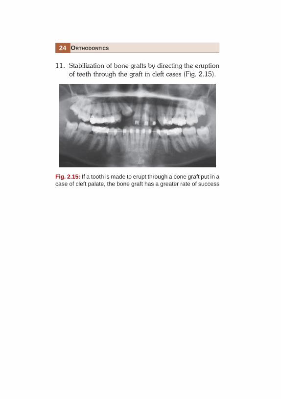
11. Stabilization of bone grafts by directing the eruptionof teeth through the graft in cleft cases (Fig. 2.15).
Fig. 2.15: If a tooth is made to erupt through a bone graft put in acase of cleft palate, the bone graft has a greater rate of success

26 ORTHODONTICS
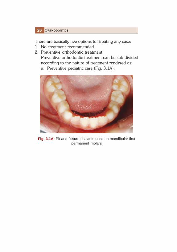
There are basically five options for treating any case:1. No treatment recommended.2. Preventive orthodontic treatment.
Preventive orthodontic treatment can be sub-dividedaccording to the nature of treatment rendered as:a. Preventive pediatric care (Fig. 3.1A).
Fig. 3.1A: Pit and fissure sealants used on mandibular firstpermanent molars

27TREATMENT OPTIONS
b. Preventive surgical treatment:i. Removal of supernumeraries (Figs 3.1Bi
and Bii).
Fig. 3.1Bi: Mesiodens is a supernumerary toothseen in the midline

28 ORTHODONTICS
Fig. 3.1Bii: Mesiodens seen erupting before the permanentmaxillary central incisors (orthopantomogram and frontal view)

29TREATMENT OPTIONS
Fig. 3.1Biii: Retained deciduous right maxillary incisor causingthe succedaneous tooth to erupt palatally (Frontal view)
Fig. 3.1Biv: Retained deciduous right maxillary incisor causingthe succedaneous tooth to erupt palatally (Occlusal view)
ii. Removal of retained deciduous teeth (Fig.3.1Biii and Biv)
30 ORTHODONTICS
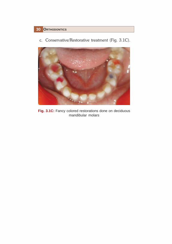
Fig. 3.1C: Fancy colored restorations done on deciduousmandibular molars
c. Conservative/Restorative treatment (Fig. 3.1C).

31TREATMENT OPTIONS
Fig. 3.1Di: Prematurity lost maxillary deciduous incisors(Courtesy: Dr Rajesh Ahal)
d. Rehabilitative treatment (3.1Di and Diii)

32 ORTHODONTICS
Fig. 3.1Dii: Acrylic teeth replacing the deciduous maxillaryincisors, retained by soldering stainless steel crowns ondeciduous molars (Occlusal view, Courtesy: Dr Rajesh Ahal)
Fig. 3.1Diii: Acrylic teeth replacing the deciduous maxillaryincisors, retained by soldering to stainless steel crowns ondeciduous molars (Frontal view, Courtesy: Dr. Rajesh Ahal)

33TREATMENT OPTIONS
3. Interceptive orthodontic treatment. Interceptiveorthodontic treatment is that phase of orthodonticsthat is employed to recognize and eliminate potentialirregularities and malpositions in the developingdentofacial complex.
Interceptive orthodontic care can be further sub-divided according to the nature of insertion andremoval of the appliance as:

34 ORTHODONTICS
Fig. 3.2Aii: Acrylic plate incorporating a mini-screw and aposterior bite-plane used to correct the lateral incisor cross-bite
Fig. 3.2Ai: Maxillary right lateral insior in cross-bite
a. Removable interceptive appliance (Fig. 3.2Aito Aiii).

35TREATMENT OPTIONS
b. Fixed interceptive appliance.i. Passive (Fig. 3.2Bi).
Fig. 3.2Bi: A passive lingual arch given to prevent loss inmandibular arch length
Fig. 3.2Aiii: Alignment of teeth following correction of lateralincisor cross-bite

36 ORTHODONTICS
Fig. 3.2Biii: Constricted maxillary arch expanded using a NiTiexpander retained by molar sheaths welded to maxillary firstmolar bands
Fig. 3.2Bii: Constricted maxillary arch with posterior teethin cross-bite
ii. Active interceptive appliance (Figs 3.2Biiand Biii).

37TREATMENT OPTIONS
c. Interception of developing deleterious habits:
Deleterious Habits
i. Thumb sucking (Fig. 3.2Ci)
Fig. 3.2Ci: Patient with the thumb sucking habit

38 ORTHODONTICS
ii. Finger sucking (Fig. 3.2Cii)
Fig. 3.2Cii: Male patient with finger sucking habit

39TREATMENT OPTIONS
Fig. 3.2Ciii: Patient with mouth breathing habit
iii. Mouth breathing (Fig. 3.2Ciii)

40 ORTHODONTICS
Fig. 3.2Civ: Typical appearance of nails of a patient withnail biting habit
iv. Nail biting (Fig. 3.2Civ)

41TREATMENT OPTIONS
v. Tongue thrusting (Fig. 3.2Cv)
Fig. 3.2Cv: Anterior tongue thrusting habit is usually associatedwith an abberent swallowing pattern and leads to proclinationand spacing between teeth

42 ORTHODONTICS
Fig. 3.2Cvi: Young may develop the habit of biting their lips
vi. Lip biting (Fig. 3.2Cvi)

43TREATMENT OPTIONS
Methods of Interception
i. Reminder/retraining appliance (Fig. 3.2Di)
Fig. 3.2Di: A removable blue grass appliance can act as areminder or a retraining device in the correction of the anteriortongue thrust habit

44 ORTHODONTICS
ii. Restraining appliance –tongue crib (Fig. 3.2Dii)
Fig. 3.2Dii: A fixed tongue crib forcefully keep thetongue from coming in contact with the anterior teeth duringswallowing
45TREATMENT OPTIONS
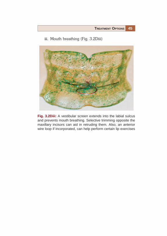
iii. Mouth breathing (Fig. 3.2Diii)
Fig. 3.2Diii: A vestibular screen extends into the labial sulcusand prevents mouth breathing. Selective trimming opposite themaxillary incisors can aid in retruding them. Also, an anteriorwire loop if incorporated, can help perform certain lip exercises

46 ORTHODONTICS
4. Corrective orthodontic treatment.Corrective orthodontic care can be further sub-divided according to the nature of the insertionand removal of the appliance as:a. Removable appliance (Figs 3.3Ai to Aiv).
Figs 3.3Ai: A trainer appliance is a commercially availableflexible appliance which is removable yet able to correct varioushabits that are basically abberant patterns associated withnormal functions

47TREATMENT OPTIONS
Fig. 3.3Aii: Anterior cross-bite with molars in a super Class Irelationship
Fig. 3.3Aiii: A 3-D expander to expand the maxillary arch bothtransversally and sagittaly
Fig. 3.3Aiv: A better alignment over all and correctionof cross-bite

48 ORTHODONTICS
b. Fixed appliance (Figs 3.3Bi to Biii).
Fig. 3.3Bi: Malalignment with crowding midline shift and end-on molar relationship on the left side
Fig. 3.3Bii: Orthodontic treatment along with non-extractiontreatment mechanics
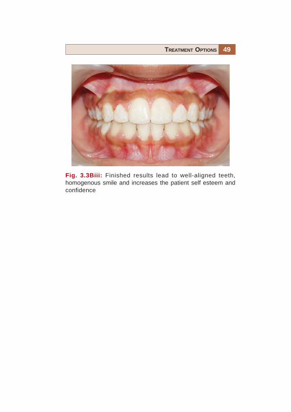
49TREATMENT OPTIONS
Fig. 3.3Biii: Finished results lead to well-aligned teeth,homogenous smile and increases the patient self esteem andconfidence

50 ORTHODONTICS
5. Inter-disciplinary treatment (Figs 3.4A and B).This includes orthodontic treatment, both fixed and/or removable so as to augment the results of treatmentas planned by other dental specialists. It should beremembered that this is a synergistic relationship andcertain cases are best treated by a team rather than anindividual.
Fig. 3.4B: Discolored maxillary central incisors can be aligned,deep bite corrected and crowned/capped with metal freeceramic crowns for optimal esthetics
Fig. 3.4A: Impacted 3rd molars can be up-righted orthodonticallyto permit there use as an abutment for bridge placed to replacethe extracted 2nd molar

52 ORTHODONTICS
Many individuals have tried to describe the elusive conceptof ‘normal occlusion’. The concepts described here arebased on Andrew’s work on 120 non-orthodontic models,based on which he gave six keys to normal occlusion anddeveloped the ‘Straight wire appliance’ in 1972.
KEY I—Inter-arch Relationship (Fig. 4.1)a. The distal surface of the distal marginal ridge of the
upper first permanent molar contacts and occludeswith the mesial surface of the mesial marginal ridge ofthe lower second molar.
b. The mesiobuccal cusp of the upper first permanentmolar falls within the groove between the mesial andmiddle cusps of the lower first permanent molar.
c. The mesiolingual cusp of the upper first molar seats inthe central fossa of the lower first molar.
Fig. 4.1: Angle’s Class I relationship

53NORMAL OCCLUSION
KEY II—Mesiodistal Crown Angulation, theMesiodistal “Tip” (Fig. 4.2)
In normally occluded teeth, the gingival portion of thelong axis of each crown is distal to the occlusal portion ofthat axis. The degree of tip varies with each tooth type.
Fig. 4.2: Mesiodistal crown angulations

54 ORTHODONTICS
KEY III—Labiolingual Crown Inclination, theLabiolingual or Buccolingual, “Torque”
• Crown inclination is the angle between a line90 degrees to the occlusal plane, and a line tangent tothe middle of the labial or buccal surface of clinicalcrown (Fig. 4.3A).
Fig. 4.3A: Labiolingual crown inclination

55NORMAL OCCLUSION
• Anterior crowns central and lateral incisors: In upperand lower incisors, the occlusal portion of the crown’slabial surface is labial to the gingival portion. In all othercrowns, the occlusal portion of the labial or buccalsurface is lingual to the gingival portion. In the non-orthodontic normal models, the average interincisalcrown angle is 134 degrees (Fig. 4.3B).
Fig. 4.3B: Interincisal angle

56 ORTHODONTICS
• Upper posterior crowns (cuspids through molars):Lingual crown inclination is slightly more pronouncedin the molars than in cuspids and bicuspids (Fig. 4.3C).
In the maxillary arch, lingual/palatal inclinationprogressively increases from cuspids/canines to molars,i.e. to say that the occlusal table of individual posteriorteeth tilts progressively towards the palate as we moveposteriorly.
Fig. 4.3C: Depiction on of the lingual crown inclinations onmaxillary posterior teeth

57NORMAL OCCLUSION
• Lower posterior crowns (cuspids through molars):Lingual inclination progressively increases (Fig. 4.3D).
In the mandibular arch, lingual inclinationprogressively increases from cuspids/canines to molars;i.e. to say that the occlusal table of individual posteriorteeth tilts progressively towards the tongue as we moveposteriorly.
Fig. 4.3D: Depiction of the lingual inclination of themandibular posterior teeth

58 ORTHODONTICS
KEY IV—Absence of Rotations
Teeth should be free of undesirable rotations (Fig. 4.4). Ifrotated, a molar or bicuspid occupies more space thannormal – a condition unreceptive to normal occlusion. Arotated incisor will occupy less space than when normallyaligned.
Rotated teeth prevent the occurrence of proper contactpoints/surfaces, they may also increase or decrease archlength. Hence absence of rotated teeth is essential for thestability of occlusion.
Fig. 4.4: Absence of rotations of teeth

59NORMAL OCCLUSION
KEY V—Presence of Tight Contacts (Fig. 4.5)
In the absence of such abnormalities as genuine tooth-size discrepancies, contact points should be tight.
Tight contacts are an essential part to maintain theintegrity of any arch form especially the dental arches.
Fig. 4.5: Presence of tight contacts

60 ORTHODONTICS
KEY VI—Flat Curve of Spee (Fig. 4.6)
A flat occlusal plane should be the treatment goal.Measured from the most prominent cusp of the lowersecond molar to the lower central incisor, no curve wasdeeper than 1.5 mm in the non-orthodontic normals.
The vertical distance between any tooth and the linejoining the most prominant cusp-tip of the mandibularmolar and central incisor (curve of Spee) should beminimal. In other words a flat curve of Spee aids in stabilityof occlusion.
Fig. 4.6: A flat curve of Spee


62 ORTHODONTICS
Angle’s Class I (Fig. 5.1)
• Mandibular arch is in normal mesiodistal relationshipwith the maxillary arch.
• The mesiobuccal cusp of the maxillary first molaroccludes in the buccal groove of the mandibular firstpermanent molar.
• The mesiolingual cusp of the maxillary first permanentmolar occludes with the central fossa of the mandibularfirst permanent molar.
Fig. 5.1: The mesiobuccal cusp of the maxillary first molaroccludes in the buccal groove of the mandibular first permanentmolar

63CLASSIFICATION OF MALOCCLUSION
Angle’s Class II (Fig. 5.2A)
• Mandibular dental arch and body are in distalrelationship with the maxillary arch.
• The mesiobuccal cusp of the maxillary first molaroccludes in the space between the mesiobuccal cuspof the mandibular first molar and the distal aspect ofthe mandibular second premolar.
Fig. 5.2A: The mesiobuccal cusp of the maxillary first molaroccludes in the space between the mesiobuccal cusp of themandibular first molar and the distal aspect of the mandibularsecond premolar

64 ORTHODONTICS
• The mesiolingual cusp of the maxillary first permanentmolar occludes mesial to the mesiolingual cusp of themandibular first molar.
• Distobuccal cusp of upper first permanent molaroccludes in the buccal groove of the lower firstpermanent molar.
Class II, Division 1 (Fig. 5.2 B)
Maxillary incisor teeth are in labio-version.
Fig. 5.2B: Increased horizontal over-lap (overjet) between theupper and lower front teeth is evident
65CLASSIFICATION OF MALOCCLUSION
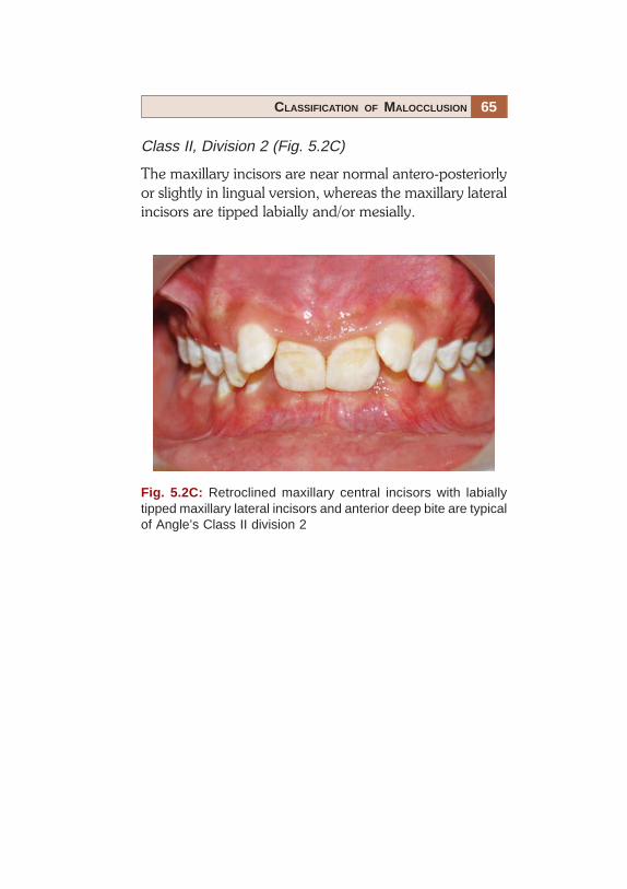
Class II, Division 2 (Fig. 5.2C)
The maxillary incisors are near normal antero-posteriorlyor slightly in lingual version, whereas the maxillary lateralincisors are tipped labially and/or mesially.
Fig. 5.2C: Retroclined maxillary central incisors with labiallytipped maxillary lateral incisors and anterior deep bite are typicalof Angle’s Class II division 2

66 ORTHODONTICS
Class II Sub-division (Fig. 5.2D)
Class II molar relationship occurs only on one side.
Fig. 5.2D: Angle’s Class I molar relationship on the right sideand Class II on the left side
67CLASSIFICATION OF MALOCCLUSION
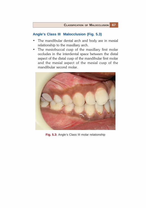
Angle’s Class III Malocclusion (Fig. 5.3)
• The mandibular dental arch and body are in mesialrelationship to the maxillary arch.
• The mesiobuccal cusp of the maxillary first molaroccludes in the interdental space between the distalaspect of the distal cusp of the mandibular first molarand the mesial aspect of the mesial cusp of themandibular second molar.
Fig. 5.3: Angle’s Class III molar relationship
68 ORTHODONTICS
Pseudo Class III
The mandible shifts anteriorly in the glenoid fossa due toa premature contact or some other reason, when the jawsare brought together in centric occlusion.
Class III Sub-division
The molar relation is Class III only on one side with thecontra later side being in Angle’s Class I.
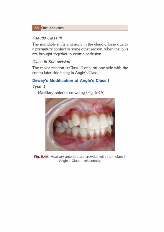
Dewey’s Modification of Angle’s Class I
Type 1
Maxillary anterior crowding (Fig. 5.4A).
Fig. 5.4A: Maxillary anteriors are crowded with the molars inAngle’s Class I relationship

69CLASSIFICATION OF MALOCCLUSION
Type 2
Maxillary incisors are proclined (Fig. 5.4B).
Fig. 5.4B: Maxillary incisors are proclined with the molars inAngle’s Class I relation

70 ORTHODONTICS
Type 3
Maxillary incisors in lingual version to mandibular incisorteeth (Fig. 5.4C). Or in other words, a negative overjetexists.
Fig. 5.4C: Maxillary incisors are lingual to the mandibularincisors with the molars in Angle’s Class I relation

71CLASSIFICATION OF MALOCCLUSION
Type 4
Molars and/or premolars in bucco/lingual version.(Fig. 5.4D).
Fig. 5.4D: Maxillary right posterior teeth in cross-bite
72 ORTHODONTICS
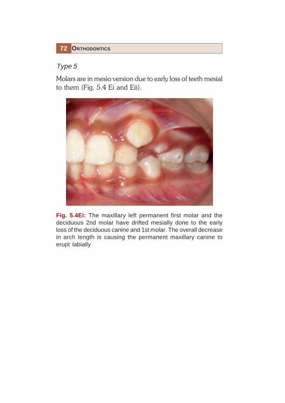
Type 5
Molars are in mesio version due to early loss of teeth mesialto them (Fig. 5.4 Ei and Eii).
Fig. 5.4Ei: The maxillary left permanent first molar and thedeciduous 2nd molar have drifted mesially done to the earlyloss of the deciduous canine and 1st molar. The overall decreasein arch length is causing the permanent maxillary canine toerupt labially

73CLASSIFICATION OF MALOCCLUSION
Fig. 5.4Eii: The mandibular left first molar (arrow) has driftedforward due to the early loss of the deciduous second molar.This will cause a decrease in the mandibular arch length and apossible impaction of the mandibular left second premolar

74 ORTHODONTICS
Dewey’s Modification of Angle’s Class III
Type 1
Individual arch is in normal alignment, but in occlusion-anteriors are in edge to edge (Fig. 5.5A).
Fig. 5.5A: First molars are in Angle’s Class III relationship withthe incisors meeting edge to edge

75CLASSIFICATION OF MALOCCLUSION
Type 2
Mandibular incisors are crowded and lingual to maxillaryincisors (Fig. 5.5B).
Fig. 5.5B: First molars are in Angle’s Class III relation with apositive overjet existing due to crowding in the mandibularanterior segment

76 ORTHODONTICS
Type 3
Maxillary arch is under developed, in cross-bite withincisors crowded (Fig. 5.5C).
Fig. 5.5C: Cleft lip and palate case with under developedmaxillary arch

77CLASSIFICATION OF MALOCCLUSION
SKELETAL CLASSIFICATION
Salzmann in 1950 was the first to classify malocclusionsaccording to the underlying skeletal structures.
Class I
Jaws in harmony with the profile being orthognathic(Fig. 5.6Ai)
Fig. 5.6Ai: A well balanced face–skeletal Class I relationship

78 ORTHODONTICS
Division 1: Local malrelationship of incisor, canine andpremolar (Fig. 5.6Aii).
Fig. 5.6Aii: Skeletal Class I relationship with localmalrelationships

79CLASSIFICATION OF MALOCCLUSION
Division 2: Maxillary incisor protrusion (Fig. 5.6 Aiii).
Fig. 5.6Aiii: Skeletal Class I relationship with maxillaryincisor protrusion

80 ORTHODONTICS
Division 3: Maxil lary incisors in l inguo-version(Fig. 5.6Aiv)
Fig. 5.6Aiv: Skeletal Class I relationship with maxillaryincisors lingually tipped
81CLASSIFICATION OF MALOCCLUSION
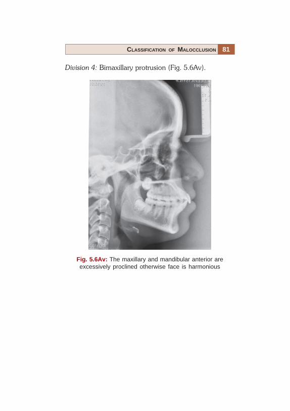
Division 4: Bimaxillary protrusion (Fig. 5.6Av).
Fig. 5.6Av: The maxillary and mandibular anterior areexcessively proclined otherwise face is harmonious

82 ORTHODONTICS
Class 2
Subnormal distal mandibular development in relation tothe maxilla.Division 1: Dental arch narrow, crowding in canine region,decreased vertical facial height, maxillary anteriorprotrusion and the profile is convex (Fig. 5.6Bi).
Fig. 5.6Bi: Mandibular arch is either under developed orretro-positioned with respect to the rest of the face
83CLASSIFICATION OF MALOCCLUSION
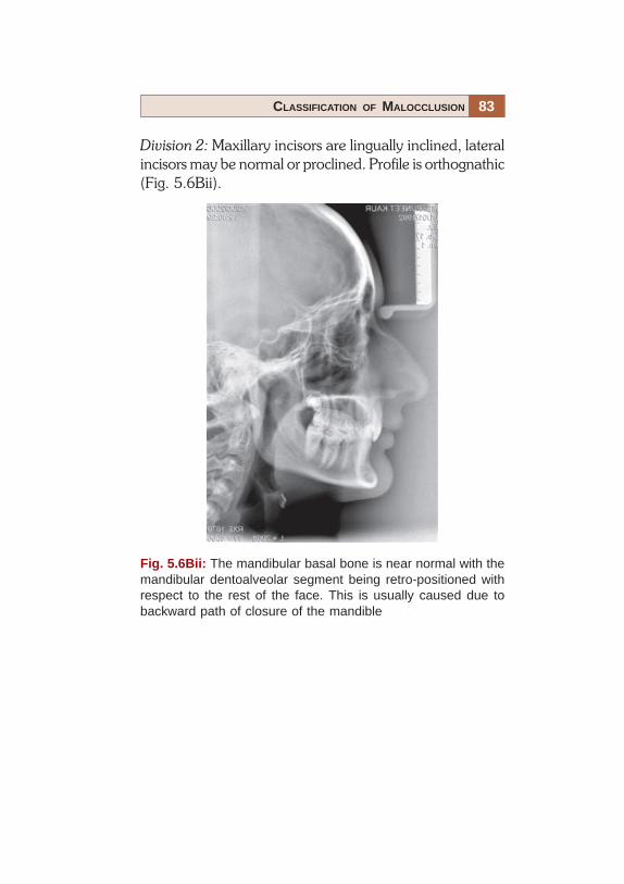
Division 2: Maxillary incisors are lingually inclined, lateralincisors may be normal or proclined. Profile is orthognathic(Fig. 5.6Bii).
Fig. 5.6Bii: The mandibular basal bone is near normal with themandibular dentoalveolar segment being retro-positioned withrespect to the rest of the face. This is usually caused due tobackward path of closure of the mandible

84 ORTHODONTICS
Class 3
Here there is an over growth of the mandible with anobtuse mandibular angle. The profile is prognathic at themandible (Fig. 5.6C).
Fig. 5.6C: The mandible is either large or forwardly placed incomparison to the rest of the face. It is a usually heriditary innature
85CLASSIFICATION OF MALOCCLUSION
INCISOR CLASSIFICATION
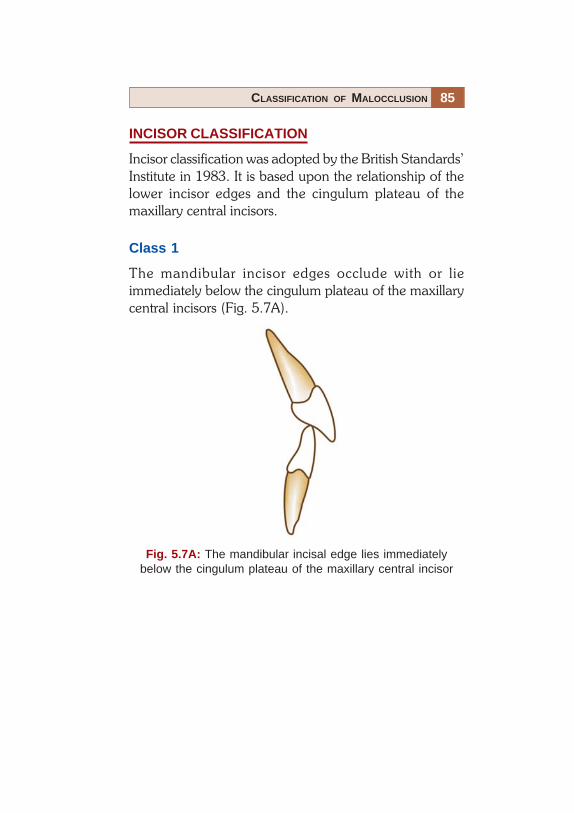
Incisor classification was adopted by the British Standards’Institute in 1983. It is based upon the relationship of thelower incisor edges and the cingulum plateau of themaxillary central incisors.
Class 1
The mandibular incisor edges occlude with or lieimmediately below the cingulum plateau of the maxillarycentral incisors (Fig. 5.7A).
Fig. 5.7A: The mandibular incisal edge lies immediatelybelow the cingulum plateau of the maxillary central incisor

86 ORTHODONTICS
Class 2
The mandibular incisor edges lie posterior to the cingulumplateau of the maxillary central incisors.• Division 1: The maxillary central incisors are proclined
or average inclination and there is an increased overjet(Fig. 5.7Bi).
Fig. 5.7Bi: The mandibular incisor edges lie posterior to thecingulum plateau of the maxillary central incisors with anincreased overjet
87CLASSIFICATION OF MALOCCLUSION
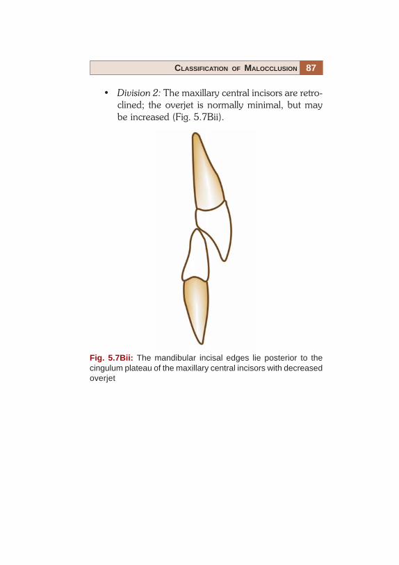
• Division 2: The maxillary central incisors are retro-clined; the overjet is normally minimal, but maybe increased (Fig. 5.7Bii).
Fig. 5.7Bii: The mandibular incisal edges lie posterior to thecingulum plateau of the maxillary central incisors with decreasedoverjet

88 ORTHODONTICS
Class 3
The mandibular incisor edges lie anterior to the cingulumplateau of the upper central incisors; the over jet is reducedor reversed (Fig. 5.7C).
Fig. 5.7C: The mandibular incisor edges lie anterior to thecingulum plateau of the upper central incisor with a reduced ornegative overjet

90 ORTHODONTICS
Self Correcting Anomalies
The most common self correcting anomaly is the uglyduckling stage.
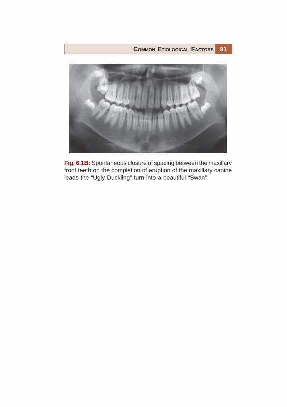
Ugly duckling stage (Figs 6.1A and B): Midline diastemamay persist even after the “ugly ducking stage” or closesimultaneously. This depends on the amount of fiberscrossing over inter-dentally and the eruption of uppercanines at their proper place in the oral cavity.
Fig. 6.1A: As the maxillary canines erupt they exert pressure onthe roots of the maxillary lateral incisors–flaring them. Theseunsightly spacing between the front teeth lead parents to consultan orthodontist
91COMMON ETIOLOGICAL FACTORS
Fig. 6.1B: Spontaneous closure of spacing between the maxillaryfront teeth on the completion of eruption of the maxillary canineleads the “Ugly Duckling” turn into a beautiful “Swan”

92 ORTHODONTICS
Anomalies of Number
Supernumerary Teeth (Figs 6.2Ai to D)
Figure 6.2Ai: “Mesiodens” is usually situated between themaxillary central incisors and can vary considerably inshape.
Supernumerary teeth are extra teeth in the oral cavitywhich may or may not bear resemblence to thepermanent teeth. The most common is the mesiodens,which occurs in the region of upper central incisors.
Fig. 6.2Ai: A mesiodens between the central incisors, leadingto the left lateral incisor erupting palatally

93COMMON ETIOLOGICAL FACTORS
Fig. 6.2Aii: Radiographic appearance of a maxillarymesiodens in occlusal view

94 ORTHODONTICS
Fig. 6.2Aiii: Mesiodens causing the impaction of the maxillaryright central incisor as seen in an orthopantomogram (OPG)

95COMMON ETIOLOGICAL FACTORS
Fig. 6.2B: “Mesiodens” in the mandibular arch
96 ORTHODONTICS
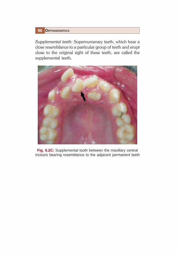
Supplemental teeth: Supernumerary teeth, which bear aclose resemblance to a particular group of teeth and eruptclose to the original sight of these teeth, are called thesupplemental teeth.
Fig. 6.2C: Supplemental tooth between the maxillary centralincisors bearing resemblance to the adjacent permanent teeth

97COMMON ETIOLOGICAL FACTORS
Fig. 6.2D: Supernumerary tooth in relation to the upper left1st and 2nd premolars

98 ORTHODONTICS
Missing Teeth (Congenital Absence (Figs 6.3A and B)or Loss due to Trauma, Caries, etc.)
Fig. 6.3A: Congenitally missing second premolars in allquadrants as seen in an orthopantomogram

99COMMON ETIOLOGICAL FACTORS
Fig. 6.3B: Teeth lost due to caries in the mandibular arch(occlusal view)

100 ORTHODONTICS
Anomalies of Tooth Size
• Microdontia• Macrodontia• True generalized macrodontia, where all the teeth are
larger than normal is seen in cases of pituitary gigantism.• Relative generalized microdontia may be seen, but is
an illusion of the true condition (Figs 6.4A and B).
Fig. 6.4A: Relative microdontia

101COMMON ETIOLOGICAL FACTORS
• Localized microdontia: Individual tooth is smaller thanthe normal size. ‘Peg lateral’ is the most commonlyseen localized microdontia, it involves the maxillarylateral incisors (Fig. 6.4B).
Fig. 6.4B: Peg-shaped maxillary left lateral incisor

102 ORTHODONTICS
Anomalies of Tooth Shape (Figs 6.5Ai to Fii)
• True fusion: When the tooth arises through the unionof two normally separated tooth germs (Figs 6.5Aito Aiii).
Fig. 6.5Ai: True fusion
103COMMON ETIOLOGICAL FACTORS
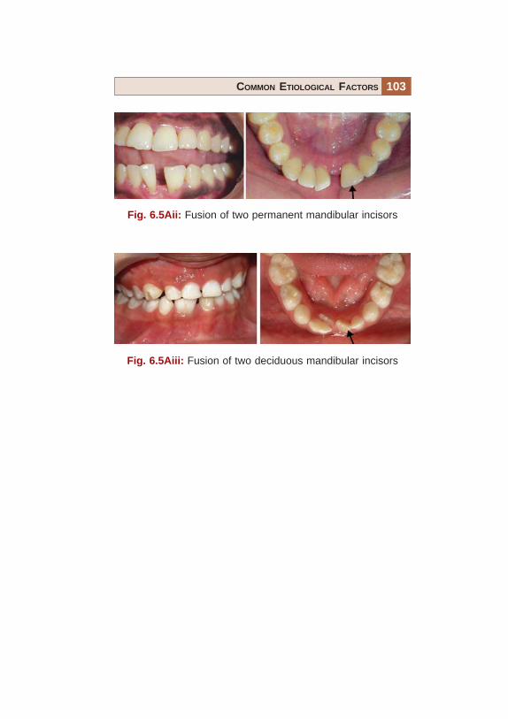
Fig. 6.5Aii: Fusion of two permanent mandibular incisors
Fig. 6.5Aiii: Fusion of two deciduous mandibular incisors

104 ORTHODONTICS
Fig. 6.5B: Germination
• Germination: These arise from division of a single toothgerm by an invagination, leading to formation of twoincomplete teeth (Fig. 6.5B).

105COMMON ETIOLOGICAL FACTORS
Fig. 6.5C: Concrescence
• Concrescence: Fusion of teeth which occurs after rootformation is complete (Fig. 6.5C).
106 ORTHODONTICS
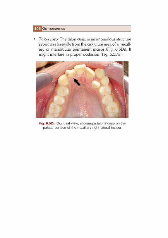
• Talon cusp: The talon cusp, is an anomalous structureprojecting lingually from the cingulum area of a maxill-ary or mandibular permanent incisor (Fig. 6.5Di). Itmight interfere in proper occlusion (Fig. 6.5Dii).
Fig. 6.5Di: Occlusal view, showing a talons cusp on thepalatal surface of the maxillary right lateral incisor

107COMMON ETIOLOGICAL FACTORS
Fig. 6.5Dii: Lateral view, showing the lower lateral incisors beinglingually displaced due to interference from the talons cusp onthe upper right lateral incisor

108 ORTHODONTICS
• Dens in dente: The term ‘Dens in dente’ is used todenote a developmental variation which radiographi-cally may resemble a tooth within a tooth (Fig. 6.5E).It rarely has any clinical significance from anorthodontic point of view.
Fig. 6.5E: 10PA shows dens in dente in mandibular1st permanent molar

109COMMON ETIOLOGICAL FACTORS
• Dilaceration: Dilaceration is also an anomaly of thetooth shape in which there is a sharp bend or curve inthe root or crown.It can effect orthodontic treatment planning (Fig.6.5Fi) and may require alteration of bracket positioningand may also complicate the extraction of the affectedtooth (Fig. 6.5Fii).
Fig. 6.5Fi: Dilacerated root of the mandibular right permanentcanine which will require alteration in bracket positioning duringorthodontic treatment

110 ORTHODONTICS
Fig. 6.5Fii: Dilaceration in the apical one-third of a maxillaryfirst premolar may complicate the extraction of such teeth

111COMMON ETIOLOGICAL FACTORS
Mucosal Barriers Abnormal Labial Frenum (Figs 6.6Aand B)
Fig. 6.6A: Frontal view, showing a high labial frenum betweenthe maxillary central incisors causing the midline spacing

112 ORTHODONTICS
Fig. 6.6B: Tongue tie

113COMMON ETIOLOGICAL FACTORS
Premature Loss (Fig. 6.7Ai to B)
• The premature Loss of a deciduous tooth can lead toa malocclusion only if the succedaneous tooth is notsufficiently close to the point of eruption.
• This can lead to a decrease in the over all arch lengthas the posterior teeth have a tendency to migratemesially (Fig. 6.7A).
Fig. 6.7Ai: Mesial of the mandibular first molar into the vacantspace created by the premature loss of a deciduous secondmandibular molar drifting can cause the second premolar tobecome impacted
114 ORTHODONTICS
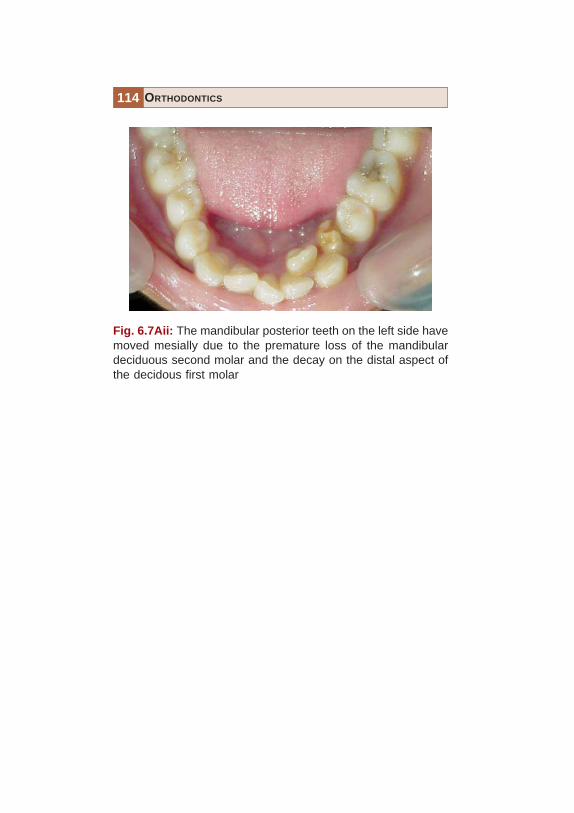
Fig. 6.7Aii: The mandibular posterior teeth on the left side havemoved mesially due to the premature loss of the mandibulardeciduous second molar and the decay on the distal aspect ofthe decidous first molar

115COMMON ETIOLOGICAL FACTORS
Fig. 6.7B: A shift in the midline of the maxillary arch towards theleft side seen due to the premature loss of the maxillary decidouscanine
• This might cause the permanent successor to eruptmalpositioned; impacted or cause a shift in the midline(in case of anterior teeth) (Fig. 6.7B).

116 ORTHODONTICS
• Prolonged retention (Figs 6.8Ai to C).
Fig. 6.8Ai: Retained maxillary deciduous canines causing thepermanent canines to erupt labially

117COMMON ETIOLOGICAL FACTORS
Fig. 6.8Aii: Retained mandibular incisors and caninescausing crowding of erupting permanent teeth
118 ORTHODONTICS
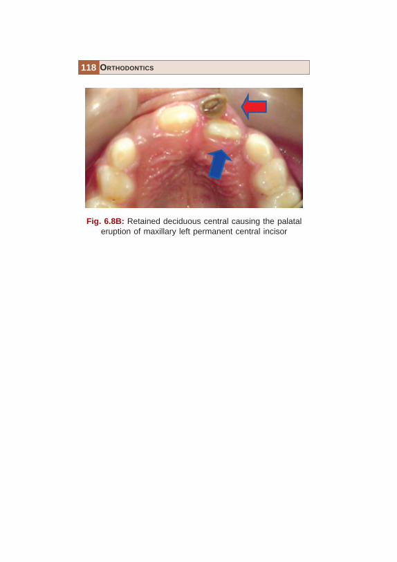
Fig. 6.8B: Retained deciduous central causing the palataleruption of maxillary left permanent central incisor

119COMMON ETIOLOGICAL FACTORS
Fig. 6.8C: Retained mandibular right deciduous canine causedthe eruption of its successor posterior to it, increasing the archlength

120 ORTHODONTICS
• Delayed eruption of permanent teeth (Fig. 6.9).
Fig. 6.9: Delayed eruption of multiple teeth in a 16 years oldfemale patient

121COMMON ETIOLOGICAL FACTORS
• Abnormal eruptive path (Figs 6.10A and B).
Fig. 6.10A: Abnormal path of eruption of the maxillaryright canine

122 ORTHODONTICS
Fig. 6.10B: Abnormal path of eruption of the mandibularleft canine

123COMMON ETIOLOGICAL FACTORS
Ankylosis is a condition which involves the union ofthe root or part of a root directly to the bone, i.e.without the intervening periodontal membrane.Ankylosis or partial ankylosis is encountered relativelyfrequently during the mixed dentition stage.
• Ankylosis (Fig. 6.11).
Fig. 6.11: Retained deciduous teeth have a high tendency toget ankylosed. If these teeth fail to erupt at the normal level, theyare also called “Submerged teeth” (arrow)

124 ORTHODONTICS
Fig. 6.12: Proximal caries on deciduous, as well as permanentteeth can lead to a loss in arch length, as the posterior teethhave a tendency to drift mesially
• Dental caries (Fig. 6.12).
125COMMON ETIOLOGICAL FACTORS
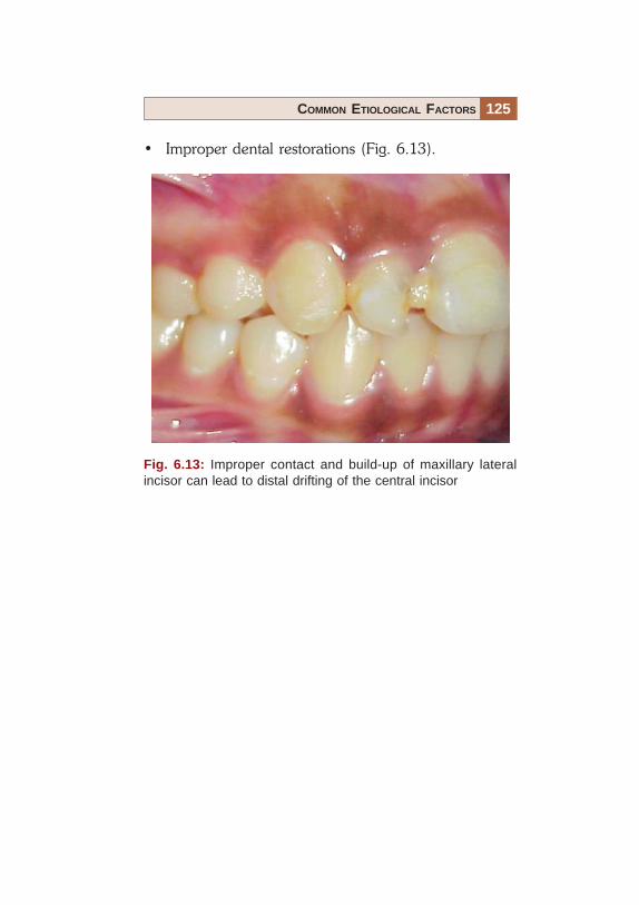
Fig. 6.13: Improper contact and build-up of maxillary lateralincisor can lead to distal drifting of the central incisor
• Improper dental restorations (Fig. 6.13).


127TREATMENT RESULTS
It is easier to accept a treatment if there is ready referenceagainst which one can compare himself or herself. Themost difficult part of clinical practice is to make a patientunderstand why healthy teeth need to be extracted aspart of the orthodontic treatment plan. This chapter willshow the results that can be achieved with good treatmentplanning and execution. Various type of extraction andnon-extraction treatment cases are presented with a viewto convince the patients that these are viable and effectivemeans to better esthetics.
128 ORTHODONTICS
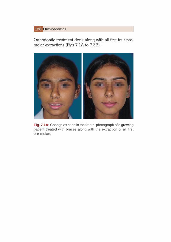
Orthodontic treatment done along with all first four pre-molar extractions (Figs 7.1A to 7.3B).
Fig. 7.1A: Change as seen in the frontal photograph of a growingpatient treated with braces along with the extraction of all firstpre-molars

129TREATMENT RESULTS
Fig. 7.1B: Change as seen in the profile photograph of a growingpatient treated with braces along with the extraction of all firstpre-molars
130 ORTHODONTICS
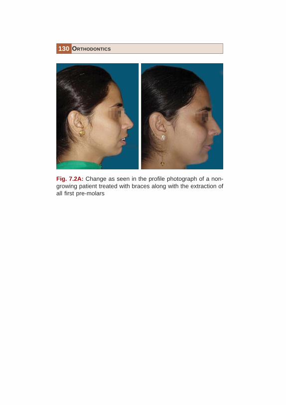
Fig. 7.2A: Change as seen in the profile photograph of a non-growing patient treated with braces along with the extraction ofall first pre-molars

131TREATMENT RESULTS
Fig. 7.2B: Change in the lip protrusion as seen in the profilephotograph of a non-growing patient treated with braces alongwith the extraction of all first pre-molars

132 ORTHODONTICS
Fig. 7.3A: Change in the smile as seen in the frontal photographof a non-growing patient treated with braces along with theextraction of all first pre-molars. Note the severe crowding ofteeth present in the dental arches

133TREATMENT RESULTS
Fig. 7.3B: Change in the intra-oral photograph of a non-growingpatient treated with braces along with the extraction of all firstpre-molars. Note the severe crowding of teeth present in thedental arches and its improvement following correction

134 ORTHODONTICS
Orthodontic treatment done along with upper first pre-molar extractions (Fig. 7.4).
Fig. 7.4: Change in the smile as seen in the frontal photographof a patient with a typical Class II division 2, treated with bracesalong with the extraction of upper first pre-molars. Note the severecrowding of teeth present in the dental arches initially

135TREATMENT RESULTS
Fig. 7.5: Change in the smile as seen in the frontal photographof a patient with a typical Class II subdivision, treated with bracesalong with the extraction of upper left pre-molar only. Note thesevere crowding of teeth present in the dental arches initially
Orthodontic treatment done along with upper left pre-molar extractions (Fig. 7.5).

136 ORTHODONTICS
Orthodontic treatment done along resolution of a tonguethrust habit (Fig. 7.6).
Fig. 7.6: Change in the smile as seen in the frontal photograph ofa patient with a typical Class I molars with persistent tongue thrust,treated with braces along with a habit breaking appliance. Notethe severe spacing of teeth present in the dental arches initially

137TREATMENT RESULTS
Fig. 7.7: Resolution of an anterior open bite caused due to asevere tongue thrust habit using fixed orthodontic appliancesalong with a fixed tongue crip
Non-extraction orthodontic treatment (Figs 7.7 to 7.13B).
Fig. 7.8: Severe crowding in the maxillary arch with molars inClass II relationship treated non-extraction, by distalization ofmaxillary arch

138 ORTHODONTICS
Fig. 7.9: Severe midline diastema closed using fixed orthodonticappliances and retained with a fixed bonded retainer on thepalatal aspect

139TREATMENT RESULTS
Fig. 7.10: Non-extraction treatment done in a crowding case.The space for the maxillary lateral incisors in cross-bite wascreated by proclining the central incisors along with proximalstripping of all the maxillary anteriors

140 ORTHODONTICS
Fig. 7.11: Change in the smile and alignment of a case in whichthe maxillary left canine erupted palatally because of an overretainer deciduous canine

141TREATMENT RESULTS
Fig. 7.12A: Case with a severely constricted maxilla, treated byexpanding the maxilla using a rapid maxillary expander andaligning the arches using a fixed orthodontic appliance

142 ORTHODONTICS
Fig. 7.12B: Case with a severely constricted maxilla, treated byexpanding the maxilla using a rapid maxillary expander andaligning the arches using a fixed orthodontic appliance. Notethe improvement in the maxillary arch contour

143TREATMENT RESULTS
Fig. 7.13A: Non-extraction treatment undertaken in a skeletalClass II patient with an under developed mandible. A fixedfunctional appliance brought about the phenomenal change inthe patients appearance

144 ORTHODONTICS
Fig. 7.13B: Non-extraction treatment undertaken in a skeletalClass II patient with an under developed mandible. A fixedfunctional appliance brought about the phenomenal change inthe patients appearance. Note the forward positioning of thechin following treatment

145TREATMENT RESULTS
Fig. 7.14: Treatment involving the segmental set-back of theanterior maxilla, along with orthodontic treatment in a case wherethe maxilla was extremely prominent
Orthognathic Surgery along with orthodontics (Fig. 7.14).

Index
AAbnormal eruptive path 121Absence of rotation of teeth 58Acrylic teeth 32
CClassification of malocclusion 61
Angle’s class I 62Angle’s class II 63Angle’s class III 67
Common etiological factors 89anomalies of number 92
missing teeth 98supernumerary teeth 92supplemental teeth 96
anomalies of tooth shape 102concrescence 105dens in dente 108dilacerations 109germination 104mucosal barriers 111talon cusp 106true fusion 102
anomalies of tooth size 100macrodontia 100microdontia 100
self-correcting anomalies 90Corrective orthodontic treatment 46
DDeciduous mandibular molars 30Dental arches 134-136Dental caries 124Dewey’s modification of Angle’s
class I 68Dewey’s modification of Angle’s
class III 74
EEsthetic brackets 3Esthetic treatment 2
FFacial contours 2Facial esthetics 11Fixed appliance 48Fixed interceptive appliance 35Fixed tongue crip 137Flat curve of spee 60
HHabit breaking appliance 136

148 ORTHODONTICS
IImplant prosthesis 18Implants 18Improper dental restorations 125Incisor classification 85
class 1 85class 2 86class 3 88
Inter-arch relationship 52Interceptive orthodontic treatment
33Interincisal angle 55
JJackson’s triad 6
LLabiolingual crown inclination 54Lip biting 42Lower posterior crowns 57
MMaxillary arch contour 142Maxillary right canine 121Mesiodens 27Mesiodistal crown angulations 53Methods of interception 43
NNail biting 40Normal occlusion 52
OOrthodontic treatment 6
aims 6esthetic harmony 10functional efficiency 7structural balance 8
Orthognathic surgery 23
PPeg lateral 101Pit and fissure sealants 26Presence of tight contacts 59Prosthetic restoration 20Proximal caries 124
RRemovable interceptive appliance
34
SSkeletal classification 77
class 1 77class 2 82class 3 84
Straight wire appliance 52
TTongue thrust habit 136Treatment results 126
U
Upper posterior crowns 56