JAWAHARLAL NEHRU TECHNOLOGICAL UNIVERSITY · PDF fileSedra A.S. and K.C. Smith,Micro...
15
JAWAHARLAL NEHRU TECHNOLOGICAL UNIVERSITY ANANTAPUR Course Structure for Electronics & Instrumentation Engineering B. Tech Course (2015-16) II B. Tech – II Sem S.No. Course Code Subject T Tu Lab C 1 15A54402 Mathematics –IV 3 1 - 3 2 15A04401 Electronic Circuit Analysis 3 1 - 3 3 15A04410 Principles of Communication 3 1 - 3 4 15A04411 Pulse and Digital Circuits 3 1 - 3 5 15A02303 Control Systems Engineering 3 1 - 3 6 15A01408 Fluid Mechanics and Hydraulic Machinery 3 1 - 3 7 15A04404 Electronic Circuit Analysis Laboratory - - 4 2 8 15A10401 Instrumentation Laboratory - - 4 2 9 15A10402 Comprehensive Online Examination-I - - - 1 Total 18 06 08 23 www.jntuking.com www.jntuking.com www.jntuking.com
Transcript of JAWAHARLAL NEHRU TECHNOLOGICAL UNIVERSITY · PDF fileSedra A.S. and K.C. Smith,Micro...

JAWAHARLAL NEHRU TECHNOLOGICAL UNIVERSITY ANANTAPUR Course Structure for Electronics & Instrumentation Engineering
B. Tech Course (2015-16)
II B. Tech – II Sem S.No. Course
Code Subject T Tu Lab C
1 15A54402 Mathematics –IV
3 1 - 3
2 15A04401 Electronic Circuit Analysis
3 1 - 3
3 15A04410 Principles of Communication
3 1 - 3
4 15A04411 Pulse and Digital Circuits
3 1 - 3
5 15A02303 Control Systems Engineering
3 1 - 3
6 15A01408 Fluid Mechanics and Hydraulic Machinery
3 1 - 3
7 15A04404 Electronic Circuit Analysis Laboratory
- - 4 2
8 15A10401 Instrumentation Laboratory
- - 4 2
9 15A10402 Comprehensive Online Examination-I
- - - 1
Total 18 06 08 23
www.jntuking.com
www.jntuking.com
www.jntuk
ing.co
m

JAWAHARLAL NEHRU TECHNOLOGICAL UNIVERSITY ANANTAPUR
II B.Tech II-Sem (E.I.E) T Tu C
3 1 3 (15A54402) MATHEMATICS –IV
(Common to ECE, EEE)
Objectives: To enable the students to understand the mathematical concepts of special functions & complex variables and their applications in science and engineering.
UNIT – I: Special Functions: Gamma and Beta Functions – their properties – Evaluation of improper integrals. Series Solutions of ordinary differential equations (Power series and Frobenius Method).
UNIT – II: Bessel functions – Properties – Recurrence relations – Orthogonality. Legendre polynomials – Properties – Rodrigue’s formula – Recurrence relations – Orthogonality.
UNIT – III
Functions of a complex variable – Continuity – Differentiability – Analyticity – Properties – Cauchy-Riemann equations in Cartesian and polar coordinates. Harmonic and conjugate harmonic functions – Milne – Thomson method.
Conformal mapping: Transformation of ez, Inz, z2, Sin z, cos z, Bilinear transformation - Translation, rotation, magnification and inversion – Fixed point – Cross ratio – Determination of bilinear transformation.
UNIT – IV
Complex integration: Line integral – Evaluation along a path and by indefinite integration – Cauchy’s integral theorem – Cauchy’s integral formula – Generalized integral formula.
Complex power series: Radius of convergence – Expansion in Taylor’s series, Maclaurin’s series and Laurent series. Singular point – Isolated singular point – Pole of order m – Essential singularity.
UNIT – V
Residue – Evaluation of residue by formula and by Laurent’s series – Residue theorem.
Evaluation of integrals of the type
www.jntuking.com
www.jntuking.com
www.jntuk
ing.co
m
(a) Improper real integrals ∫∞
∞−d xxf )( (b) ∫
+ πθθθ
2)s i n,( c o s
c
cdf (c) ∫
∞
∞−d xxfei m x )(
TEXT BOOKS: 1. Higher Engineering Mathematics, B.S.Grewal, Khanna publishers. 2. Engineering Mathematics, Volume - III, E. Rukmangadachari & E. Keshava Reddy, Pearson
Publisher REFERENCES:
1. Mathematics III by T.K.V. Iyengar, B.Krishna Gandhi, S.Ranganatham and M.V.S.S.N.Prasad, S.Chand publications.
2. Advanced Engineering Mathematics, Peter V.O’Neil, CENGAGE publisher. 3. Advanced Engineering Mathematics by M.C. Potter, J.L. Goldberg, Edward F.Aboufadel,
Oxford. Outcomes: The student achieves the knowledge to analyse the problems using the methods of special functions and complex variables
www.jntuking.com
www.jntuking.com
www.jntuk
ing.co
m

JAWAHARLAL NEHRU TECHNOLOGICAL UNIVERSITY ANANTAPUR
II B.Tech II-Sem (E.I.E) T Tu C
3 1 3 (15A04401) ELECTRONIC CIRCUIT ANALYSIS
Course Objectives: The aim of this course is to familiarize the student with the analysis and design of multistage amplifiers with compound connections, feedback amplifiers, oscillators, power amplifiers and tuned amplifiers. To study and analyze the frequency response of amplifier circuits. Course Outcomes: Upon completion of this course, student will be able to :
• Analyze the frequency response of the BJT amplifiers at low and high frequencies. • Analyze and design multistage amplifiers with compound connections, feedback
amplifiers, oscillators, power amplifiers and tuned amplifiers.
UNIT -I Feedback Amplifiers : Feedback principle and concept, types of feedback, classification of amplifiers, feedback topologies,Characteristics of negative feedback amplifiers, Generalized analysis of feedback amplifiers, Performance comparison of feedback amplifiers, Method of Analysis of Feedback Amplifiers.
Oscillators: Oscillator principle, condition for oscillations, types of oscillators, RC-phase shift and Wein bridge oscillators with BJT and FET with the relevant analysis,Generalized analysis of LC Oscillators, Hartley and Colpitt’s oscillators with BJT and FET with relevant analysis, Crystal oscillators, Frequency and amplitude stability of oscillators.
UNIT- II Small Signal High Frequency Transistor Amplifier models: BJT: Transistor at High Frequencies, Hybrid- π Common Emitter transistor model, Hybrid π conductances, Hybrid π capacitances, Validity of hybrid π model, determination of high-frequency parameters in terms of low-frequency parameters , CE short circuit current gain, Current gain with resistive load, Cut-off frequencies, Frequency Response and Gain Bandwidth product.
FET:Analysis of Common Source and Common Drain Amplifier circuits at High frequencies.
UNIT – III Multistage Amplifiers : Classification ofamplifiers, Methods of coupling, Cascaded transistor amplifier and its analysis, Analysis of two stage RC coupled amplifier, High input resistance transistor amplifier circuits and their analysis-Darlington pair amplifier, Cascode amplifier,
www.jntuking.com
www.jntuking.com
www.jntuk
ing.co
m

Boot-strap emitter follower, Analysis of multi stage amplifiers using FET, Differential amplifier using BJT.
UNIT- IV Power Amplifiers: Class A large signal Amplifiers, Second harmonic Distortions, Higher order harmonic Distortion, Transformer Coupled Audio power amplifier, Efficiency, Push-pull amplifiers, Class B Amplifiers, Class AB operation, Efficiency of Class B Amplifier, Complementary Symmetry push pull amplifier, Class D amplifier, Class S amplifier, MOSFET power amplifier, Thermal stability and Heat sink. UNIT -V Tuned Amplifiers : Introduction, Q-Factor, Small Signal Tuned Amplifier – Capacitance single tuned amplifier, Double Tuned Amplifiers, Effect of Cascading Single tuned amplifiers on Band width, Effect of Cascading Double tuned amplifiers on Band width, Staggered tuned amplifiers, Stability of tuned amplifiers
Text Books: 1. J. Millman and C.C. Halkias, “Integrated Electronics”, McGraw-Hill, 1972. 2. Donald A. Neaman, “Electronic Circuit Analysis and Design”, McGraw Hill. 3. Salivahanan, N.Suressh Kumar, A. Vallavaraj, “Electronic Devices and Circuits”, Tata
McGraw Hill, Second Edition.
References: 1. Robert T. Paynter, “Introductory Electronic Devices and Circuits”, Pearson Education, 7th
Edition 2. Robert L. Boylestad and Louis Nashelsky, “Electronic Devices and Circuits Theory”
Pearson/Prentice Hall, 9th Edition, 2006. 3. Sedra A.S. and K.C. Smith, “Micro Electronic Circuits”, Oxford University Press, 5th
Edition.
www.jntuking.com
www.jntuking.com
www.jntuk
ing.co
m
JAWAHARLAL NEHRU TECHNOLOGICAL UNIVERSITY ANANTAPUR
II B.Tech II-Sem (E.I.E) T Tu C
3 1 3
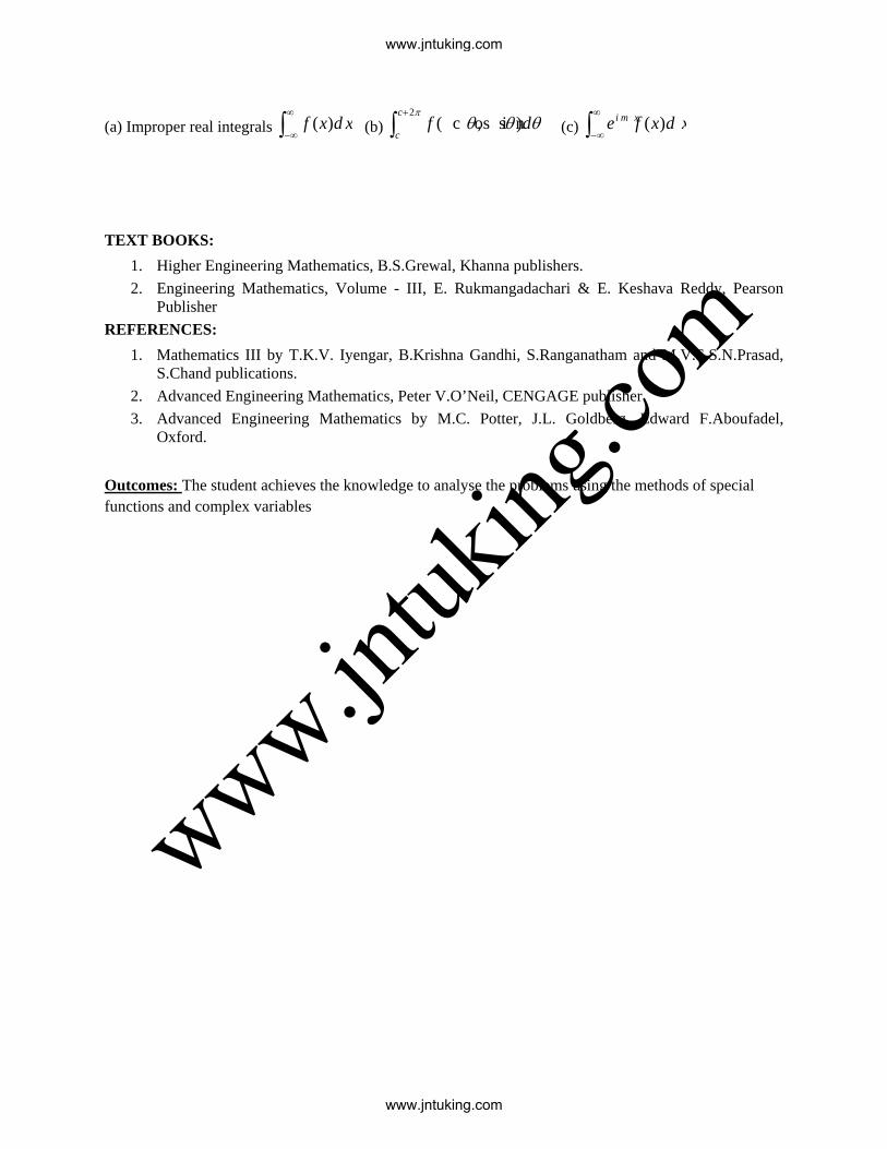
(15A04410) PRINCIPLES OF COMMUNICATION Learning Outcome: On successful completion of the module students will be able to
• explain the main concepts of analogue and digital communication systems; • analyze and design an AM and FM modulator/demodulator; • explain, discuss, and compare different binary digital modulation
techniques; explain types of noise & effects of noise on communication system UNIT I Introduction: Block diagram of Electrical communication system, Radio communication : Types of communications, Analog, pulse and digital Types of signals, Noise – Types of noise, sources of noise, calculation of noise in Linear systems, and noise figure. UNIT II Amplitude Modulation: Need for modulation, Types of Amplitude modulation, AM, DSB SC, SSB SC, Power and BW requirements, generation of AM, DSB SC, SSB SC, Demodulation of AM : Diode detector, Product demodulation for DSB SC & SSB SC. Angle Modulation : Frequency & Phase modulations, advantages of FM over AM, Bandwidth consideration, Narrow band and Wide band FM, Comparison of FM & PM. UNIT III Pulse Modulations: Sampling, Nyquist rate of sampling, Sampling theorem for Band limited signals, PAM, regeneration of base band signal, PWM and PPM, Time Divison Multiplexing, Frequency Divison Multiplexing, Asynchronous Multiplexing. UNIT IV Digital Communication: Advantages, Block diagram of PCM, Quantization, effect of quantization, quantization error, Base band digital signal, DM, ADM, ADPCM and comparison. Digital Modulation: ASK, FSK, PSK, DPSK, QPSK demodulation, coherent and incoherent reception, Modems. UNIT V Information Theory : Concept of information, rate of information and entropy, Source coding for optimum rate of information, Coding efficiency, Shanon-Fano and Huffman coding. Error control coding : Introduction, Error detection and correction codes, block codes, convolution codes. Text Books: 1. Communication Systems Analog and Digital – R.P. Singh and SD Sapre, TMH, 20th
reprint, 2004. 2. Principles of Communications – H. Taub and D. Schilling, TMH, 2003. Reference Books: 1. Electronic Communication Systems – Kennedy and Davis, TMH, 4th edition, 2004. 2. Communication Systems Engineering – John. G. Proakis and Masoud Salehi, PHI, 2nd Ed.
2004.
www.jntuking.com
www.jntuking.com
www.jntuk
ing.co
m
JAWAHARLAL NEHRU TECHNOLOGICAL UNIVERSITY ANANTAPUR
II B.Tech II-Sem (E.I.E) T Tu C
3 1 3
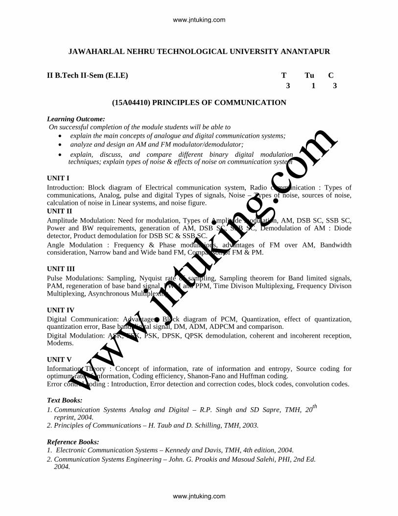
(15A0411) PULSE AND DIGITAL CIRCUITS Course Objective:
• To study various wave shaping circuits and their applications. • To study different circuits that produce non-sinusoidal waveforms(multivibrators) and their
applications • To study various voltage time base generators and their applications. • To study different logic families and their comparison.
Learning Outcome:
• Students will be able to design different pulse circuits based on the above concepts. UNIT I LINEAR WAVESHAPING High pass, low pass RC circuits, their response for sinusoidal, step, pulse, square and ramp inputs. High Pass RC network as Differentiator, Low Pass RC network as integrator, attenuators and its applications as a CRO probe, RL circuits and its response for step input, Illustrative Problem . UNIT II NON-LINEAR WAVE SHAPING Diode clippers, Transistor clippers, clipping at two independent levels, Comparators, applications of voltage comparators, clamping operation, clamping circuits taking source and Diode resistances into account, Clamping circuit theorem, practical clamping circuits, effect of diode characteristics on clamping voltage, Synchronized Clamping. UNIT III MULTIVIBRATORS Transistor as a switch, Break down voltages, Transistor-Switching Times, Triggering circuits. Analysis
and Design of Bistable, Monostable, Astable Multivibrators and Schmitt trigger circuit using BJT. UNIT IV TIME BASE GENERATORS General features of a time base signal, methods of generating time base waveform, Miller and Bootstrap time base generators – basic principles, Transistor miller time base generator, Transistor Bootstrap time base generator, Transistor Current time base generators, Methods of linearity Improvements. SYNCHRONIZATION AND FREQUENCY DIVISION Pulse Synchronization of relaxation Devices, Frequency division in sweep circuit, Stability of relaxation Devices, Astable relaxation circuits, Monostable relaxation circuits, Synchronization of a sweep circuit with symmetrical signals. UNIT V SAMPLING GATES Basic operating principles of sampling gates, Unidirectional and Bi-directional sampling gates, Four Diode Sampling Gate, Reduction of pedestal in gate circuits, Six Diode Gate, Application of Sampling Gates.
www.jntuking.com
www.jntuking.com
www.jntuk
ing.co
m

Digital Logic Circuits: AND, OR, & NOT gates using Diodes, and Transistors, Analysis of DCTL, RTL, DTL, TTL, ECL and CMOS Logic Families, and comparison between the logic families. Text Books: 1. J.Millman, H.Taub and Mothiki S. Prakash Rao, ― Pulse, Digital and Switching Waveforms‖
,TMH ,2nd Edition, 2008. 2. David A. Bell, ―Solid State Pulse Circuits‖, PHI, 4th edition, 2002. Reference Books: 1. Jacob Millman, Christos C. Halkias, ―Integrated electronics‖ Tata McGraw Hill Publication 2. A. Anand Kumar, ―Pulse and Digital Circuits‖, PHI, 2005. 3. Ronald J. Tocci, ―Fundamentals of Pulse and Digital Circuits‖, 3rd edition, 2008.
www.jntuking.com
www.jntuking.com
www.jntuk
ing.co
m

JAWAHARLAL NEHRU TECHNOLOGICAL UNIVERSITY ANANTAPUR
II B.Tech II-Sem (E.I.E) T Tu C
3 1 3
(15A02303) CONTROL SYSTEMS ENGINEERING OBJECTIVES: To make the students learn about:
• Merits and demerits of open loop and closed loop systems; the effects of feedback
• The use of block diagram algebra and Mason’s gain formula to find the effective transfer
function between two nodes
• Transient and steady state responses , time domain specifications
• The concept of Root loci
• Frequency domain specifications, Bode diagrams and Nyquist plots
• The fundamental aspects of modern control
UNIT – I INTRODUCTION Open Loop and closed loop control systems and their differences- Examples of control systems-
Classification of control systems, Feedback Characteristics, Effects of positive and negative
feedback. Mathematical models – Differential equations of Translational and Rotational
mechanical systems, and Electrical Systems, Block diagram reduction methods – Signal flow
graph - Reduction using Mason’s gain formula. Transfer Function of DC Servo motor - AC
Servo motor - Synchro transmitter and Receiver
UNIT-II TIME RESPONSE ANALYSIS Step Response - Impulse Response - Time response of first order systems – Characteristic
Equation of Feedback control systems, Transient response of second order systems - Time
domain specifications – Steady state response - Steady state errors and error constants
UNIT – III STABILITY The concept of stability – Routh’s stability criterion – Stability and conditional stability –
limitations of Routh’s stability. The root locus concept - construction of root loci-effects of
adding poles and zeros to G(s)H(s) on the root loci.
www.jntuking.com
www.jntuking.com
www.jntuk
ing.co
m

UNIT – IV FREQUENCY RESPONSE ANALYSIS Introduction, Frequency domain specifications-Bode diagrams-Determination of Frequency
domain specifications and transfer function from the Bode Diagram-Stability Analysis from
Bode Plots. Polar Plots-Nyquist Plots- Phase margin and Gain margin-Stability Analysis.
Compensation techniques – Lag, Lead, Lag-Lead Compensator design in frequency Domain.
UNIT – V STATE SPACE ANALYSIS Concepts of state, state variables and state model, derivation of state models from differential
equations. Transfer function models. Block diagrams. Diagonalization. Solving the Time
invariant state Equations- State Transition Matrix and it’s Properties. System response through
State Space models. The concepts of controllability and observability.
OUTCOMES: After completing the course, the student should be able to do the following:
• Evaluate the effective transfer function of a system from input to output using (i) block
diagram reduction techniques (ii) Mason’s gain formula
• Compute the steady state errors and transient response characteristics for a given system
and excitation
• Determine the absolute stability and relative stability of a system
• Draw root loci
• Design a compensator to accomplish desired performance
• Derive state space model of a given physical system and solve the state equation
TEXT BOOKS: 1. Modern Control Engineering, Katsuhiko Ogata, PEARSON, 1st Impression 2015. 2. Control Systems Engineering, I. J. Nagrath and M. Gopal, New Age International Publishers,
5th edition, 2007, Reprint 2012. REFERENCE BOOKS: 1. Automatic Control Systems, Farid Golnaraghi and Benjamin. C. Kuo, WILEY, 9th Edition,
2010. 2. Control Systems, Dhanesh N. Manik, CENGAGE Learning, 2012. 3. John J D’Azzo and C. H. Houpis , “Linear Control System Analysis and Design: Conventional and
Modern”, McGraw - Hill Book Company, 1988.
www.jntuking.com
www.jntuking.com
www.jntuk
ing.co
m
JAWAHARLAL NEHRU TECHNOLOGICAL UNIVERSITY ANANTAPUR
II B.Tech II-Sem (E.I.E) T Tu C
3 1 3
(15A01408) FLUID MECHANICS AND HYDRAULIC MACHINERY
UNIT I INTRODUCTION: Dimensions and units – physical properties of fluids, specific gravity, viscosity,
surface tension and capillarity, vapor pressure and their influences on fluid motion. Newtonian and non Newtonian fluids. Fluid Pressure at a Point; Pascal’s law, Hydrostatic law, , Atmospheric, Absolute and gauge pressure; Hydrostatic paradox, Pressure measurement manometers; Simple, differential and Micro Manometers KINEMATICS OF FLUID MOTION: Methods of describing fluid motion; Classification of flow; Steady, unsteady, uniform and non-uniform flows; Laminar and turbulent flows; Three, two and one dimensional flows; Irrotational and rotational flows; Streamline; Pathline; Streakline; Equation for acceleration; Convective accelaration; Local acceleration; Continuity equation; Velocity potential and stream function; Flownet. UNIT II DYNAMICS OF FLUID FLOW: Forces acting on a Fluid in Motion; Euler’s equation of motion; .Bernoulli’s equation ; Energy correction factor; Momentum principle; Force exerted on a pipe bend. Discharge through Venturi Meter; Discharge through Orifice Meter; Discharge through flow nozzle; Measurement of velocity by Pitot tube,pitot-static tube. CLOSED CONDUIT FLOW: Energy losses in pipelines; Darcy – Weisbach equation; Minor losses in pipelines; Hydraulic Grade Line and Total Energy Line; Concept of equivalent length; Hydraulic power transmission through a pipe; Siphon; Pipes in series, parallel & branched pipes. UNIT– III BASICS OF TURBO MACHINERY: Hydrodynamic force of jets on stationary and moving flat, inclined and curved vanes, jet striking centrally and at tip, velocity triangles at inlet and outlet, expressions for work done and efficiency-Angular momentum principle, Torque and head transferred in roto dynamic machines. HYDRAULIC TURBINES-I: Introduction, head and efficiencies of hydraulic turbines, Classification of turbines; pelton wheel: parts, Velocity triangles, work done and efficiency, working proportions, design of pelton wheel. Radial flow reaction turbines: velocity triangles and work done for inward radial flow turbine, degree of reaction, discharge, speed ratio, flow ratio. UNIT IV HYDRAULIC TURBINES-II: Francis turbine: main components and working, work done and efficiencies, design proportions; design of francis turbine runner. Kaplan turbine: main components and working, working proportions. Draft tube: theory and efficiency; specific speed, unit quantities, characteristic curves of hydraulic turbines. Cavitation: causes, effects. CENTRIFUGAL PUMPS: Introduction, component parts and working of a centrifugal pump, work done by the impeller; heads, losses and efficiencies; minimum starting speed; Priming ;specific speed; limitation of suction lift, net positive suction head(NPSH);Performance and characteristic curves; Cavitation effects ;Multistage centrifugal pumps; troubles and remedies.
www.jntuking.com
www.jntuking.com
www.jntuk
ing.co
m
UNIT V HYDRO ELECTRIC POWER STATION: Development of hydro power in Andhra Pradesh and India; Classification of hydel plants- runoff river plants, storage plants and pumped storage plants; low, medium and high head schemes ;Investigation and planning; components of hydel schemes – fore bay, intake structure, surge tanks, penstocks ,power house, turbines-selection of suitable type of turbine, Scroll casing ,draft tube and tail race; assessment of available power; definition of gross head ,operating head ,effective head; , hydrographs, Flow duration curve; Power duration curve; Load duration curve; Load curve ; primary power and secondary power; installed capacity, dependable capacity; firm power, secondary power; power factor ;load factor, capacity factor ,utilization factor and Diversity factor. Text Books: 1. Hydraulics & Fluid Mechanics by P. N. Modi & S. N. Seth; Standard Book house, New Delhi 2. Fluid Mechanics & Hydraulic Machines by Dr. R. K. Bansal; Laxmi Publications, New Delhi. Reference Books 1. Hydraulic Machines by Jagdish Lal, Metropolitan. 2. Fluid Mechanics by A. K. Jain; Khanna Publishers, Delhi 3. Fluid mechanics and fluid machines by Rajput, S.Chand &Co. 4. Fluid Mechanics & Fluid Power Engineering by D.S. Kumar Kataria & Sons. 5. Fluid Mechanics, Hydraulics and Hydraulic Machines by K R Arora, Standard Publishers 6. Engineering Fluid Mechanics by Kumar K.L., Eurasia Publishing House (P) Ltd., New Delhi
www.jntuking.com
www.jntuking.com
www.jntuk
ing.co
m

JAWAHARLAL NEHRU TECHNOLOGICAL UNIVERSITY ANANTAPUR
II B.Tech II-Sem (E.I.E) L C
4 2
(15A04404) ELECTRONIC CIRCUIT ANALYSIS LABORATORY
Note:The students are required to design the electronic circuit and they have to perform the analysis through simulator using Multisim/Pspice/Equivalent Licensed simulation software tool. Further they are required to verify the result using necessary hardware in the hardware laboratory.
Objectives
• Help students make transition from analysis of electronic circuits to design of electronic circuits.
• To understand the Analysis of transistor at high frequencies.
• To understand the concept of designing of tuned amplifier.
• The student will construct and analyze voltage regulator circuits.
• To understand the circuit configuration and the principle operation of converters, including diode rectifiers, controlled AC-DC converters and DC choppers
Outcomes:
• The ability to analyze and design single and multistage amplifiers at low, mid and high frequencies.
• Designing and analyzing the transistor at high frequencies.
• Determine the efficiencies of power amplifiers.
• Determine Frequency response and design of tuned amplifiers.
• Able to Analyze all the circuits using simulation software and Hardware. PART A: List of Experiments :( Minimum of Ten Experiments has to be performed)
1. Determination of fT of a given transistor. 2. Voltage-Series Feedback Amplifier 3. Current-Shunt Feedback Amplifier 4. RC Phase Shift/Wien Bridge Oscillator 5. Hartley/Colpitt’s Oscillator 6. Two Stage RC Coupled Amplifier 7. Darlington Pair Amplifier 8. Bootstrapped Emitter Follower 9. Class A Series-fed Power Amplifier 10. Transformer-coupled Class A Power Amplifier 11. Class B Push-Pull Power Amplifier 12. Complementary Symmetry Class B Push-Pull Power Amplifier 13. Single Tuned Voltage Amplifier 14. Double Tuned Voltage Amplifier
www.jntuking.com
www.jntuking.com
www.jntuk
ing.co
m

PART B: Equipment required for Laboratory Software:
i. Multisim/ Pspice/Equivalent Licensed simulation software tool ii. Computer Systems with required specifications
Hardware:
1. Regulated Power supplies 2. Analog/Digital Storage Oscilloscopes 3. Analog/Digital Function Generators 4. Digital Multimeters 5. Decade Résistance Boxes/Rheostats 6. Decade Capacitance Boxes 7. Ammeters (Analog or Digital) 8. Voltmeters (Analog or Digital) 9. Active & Passive Electronic Components 10. Bread Boards 11. Connecting Wires
CRO Probes etc.
www.jntuking.com
www.jntuking.com
www.jntuk
ing.co
m

JAWAHARLAL NEHRU TECHNOLOGICAL UNIVERSITY ANANTAPUR
II B.Tech II-Sem (E.I.E) L C
4 2
(15A10401) INSTRUMENTATION LABORATORY
Course Objective: Hands on experience in industrial instrumentation Learning Outcome: The students are expected to acquire practical knowledge of the instruments
used in any industry. (Minimum TEN experiments should be performed) 1. Extension of Range of DC Ammeter, Voltmeter 2. Extension of Range of AC Voltmeter, Ammeter 3. Construction of series & shunt type ohm meters using PMMC 4. RLC and Q measurement using Q-meter 5. Study of strain gauges using any one application 6. Measurement of temperature using RTD 7. Measurement of linear displacement using LVDT 8. Study of capacitive transducers 9. Measurement of resistance using wheat stone bridge / Kelvin bridge 10. Measurement of capacitance using shearing bridge 11. Measurement of inductance using maxwell’s bridge 12. Characteristics of Opto- Electric Transducers (photo transistor, photo
diode, LDR) 13. Piezoelectric transducers 14. Bourdon tube 15. Acceleration transducers
www.jntuking.com
www.jntuking.com
www.jntuk
ing.co
m


![K.C. Electric Is a Nonprofit Electric Cooperative K. …...K.C. ELECTRIC ASSOCIATION [Country News]coloradocountrylife.coop NOVEMBER 2015 7K. K.C. Electric Association is a nonprofit](https://static.fdocuments.in/doc/165x107/5f8b427967b3c91bd9221f78/kc-electric-is-a-nonprofit-electric-cooperative-k-kc-electric-association.jpg)