JARAG-5 User Manual - Accueil - Chromlech menu structure ..... 10 5. DMX control ..... 12 ......
29
JARAG-5 User Manual Rev D JA121 - JA221 FW V2.3
Transcript of JARAG-5 User Manual - Accueil - Chromlech menu structure ..... 10 5. DMX control ..... 12 ......
JARAG-5
User ManualRev D
JA121 - JA221FW V2.3
ChromlechChromlech
19, avenue Gabriel Fauré35235 THORIGNE-FOUILLARD
FRANCE
Tel: +33 (0)2.23.20.77.67Fax: +33 (0)2.23.20.75.71
E-mail: [email protected]
Web: www.chromlech.com

Table of Contents
Table of Contents ............................................................................................................... 1
1. The JARAG-5 .................................................................................................................. 2 Lamp array ................................................................................................................................ 2 Internal sequencer .................................................................................................................... 2 6 DMX channel personality ........................................................................................................ 3 25 DMX channel personality ...................................................................................................... 3 31 DMX channel personality ...................................................................................................... 3 JA121 dimensions .................................................................................................................... 4 JA221 dimensions .................................................................................................................... 4
2. Installation ....................................................................................................................... 5 Direct fastening ......................................................................................................................... 5 Using the yoke mounting ........................................................................................................... 5 Stacking arrays ......................................................................................................................... 5
3. Precautions in use .......................................................................................................... 6
4. Control panel ................................................................................................................... 7 Connectors ................................................................................................................................ 8 Indicators .................................................................................................................................. 9 Setup menu ............................................................................................................................. 10 Setup menu structure .............................................................................................................. 10
5. DMX control .................................................................................................................. 12 6 channel personality (sequences) .......................................................................................... 12 25 channel personality (matrix) ............................................................................................... 14 31 channel personality (dual) .................................................................................................. 14
6. Programming ................................................................................................................ 15
7. Specifications ................................................................................................................ 16
8. Part numbers ................................................................................................................ 16
Sequence table ................................................................................................................ 17
JARAG-5 User Manual 1

1. The JARAG-5
The JARAG-5 provides the same light output as a conventional lighting system but can be used to create a wide range of lighting effects. The dimmers, sequencer and control interfaces are built in so that the system can be installed simply and easily. It only requires a mains supply and an external DMX controller.
Lamp arrayThe JARAG-5 has a 25 lamp array. The type of lamp used depends on the lighting system model: The JA121 takes PAR20 lamps (GU10), and the JA221 takes PAR30 lamps (E26).The lamps are controlled individually by a built-in 25 channel dimmer.
Internal sequencer
The lighting system has an internal sequencer which makes it easier to control the lamp array. The sequencer can store up to 256 sequences.
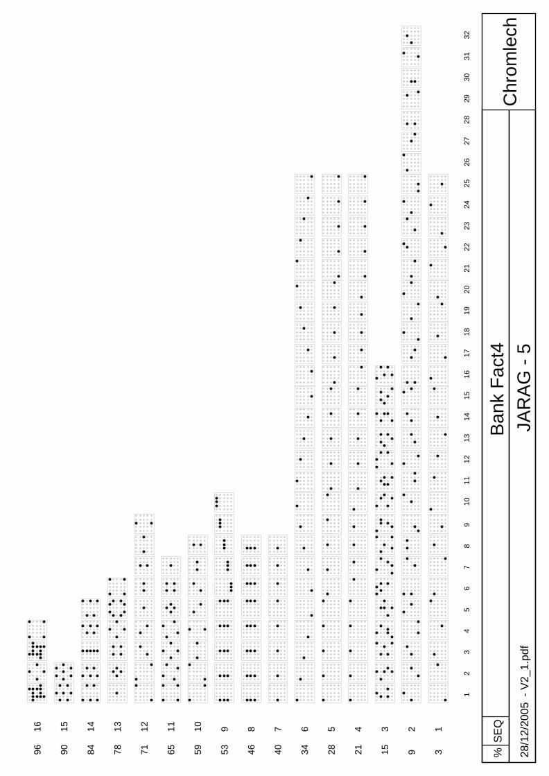
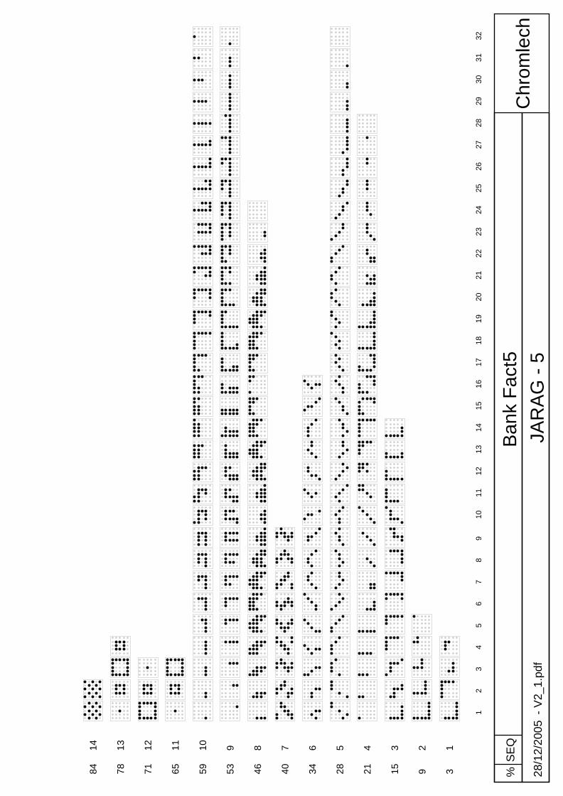
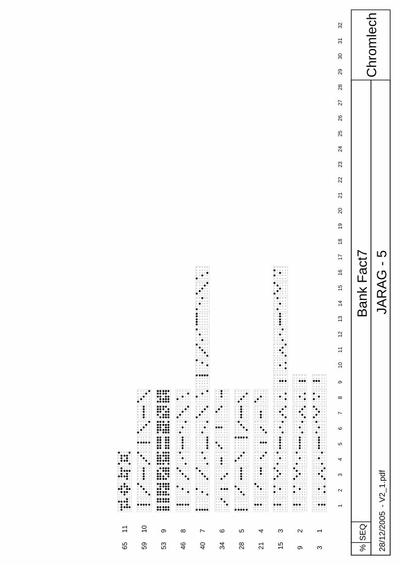
A sequence is a series of steps (maximum 32) played in a loop and the brightness, speed and effects can be adjusted in real time. Each step defines the state of each of the 25 lamps.
The sequences are stored in 16 banks of 16 sequences. The sequences for banks 1 to 8 are factory set and cannot be changed. These sequences are common to all JARAG-5s and provide a firm basis for creating lighting effects with the same controls for any lighting system (see description of sequences in the appendix).
The sequences for banks 9 to 16 can be defined by the user. These sequences allow each lighting system to be set up to meet the user's requirements.
The sequences are programmed using special software supplied free of charge (downloaded from www.chromlech.com) that operates under PC/Windows. The sequences can be defined and then uploaded into the lighting systems. A graphic interface allows for simulating the sequences that have been defined.
2 JARAG-5 User Manual
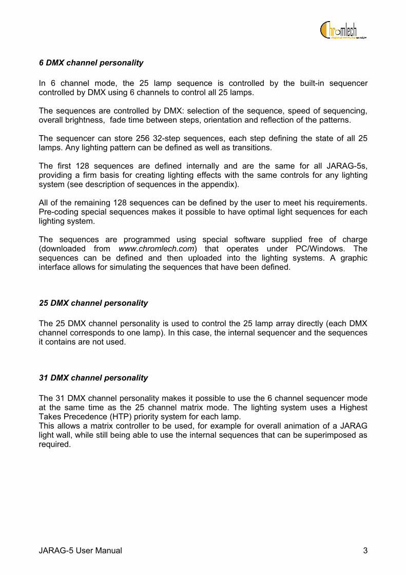
6 DMX channel personality
In 6 channel mode, the 25 lamp sequence is controlled by the built-in sequencer controlled by DMX using 6 channels to control all 25 lamps.
The sequences are controlled by DMX: selection of the sequence, speed of sequencing, overall brightness, fade time between steps, orientation and reflection of the patterns.
The sequencer can store 256 32-step sequences, each step defining the state of all 25 lamps. Any lighting pattern can be defined as well as transitions.
The first 128 sequences are defined internally and are the same for all JARAG-5s, providing a firm basis for creating lighting effects with the same controls for any lighting system (see description of sequences in the appendix).
All of the remaining 128 sequences can be defined by the user to meet his requirements. Pre-coding special sequences makes it possible to have optimal light sequences for each lighting system.
The sequences are programmed using special software supplied free of charge (downloaded from www.chromlech.com) that operates under PC/Windows. The sequences can be defined and then uploaded into the lighting systems. A graphic interface allows for simulating the sequences that have been defined.
25 DMX channel personality
The 25 DMX channel personality is used to control the 25 lamp array directly (each DMX channel corresponds to one lamp). In this case, the internal sequencer and the sequences it contains are not used.
31 DMX channel personality
The 31 DMX channel personality makes it possible to use the 6 channel sequencer mode at the same time as the 25 channel matrix mode. The lighting system uses a Highest Takes Precedence (HTP) priority system for each lamp. This allows a matrix controller to be used, for example for overall animation of a JARAG light wall, while still being able to use the internal sequences that can be superimposed as required.
JARAG-5 User Manual 3
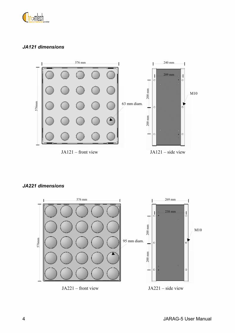
JA121 dimensions
JA221 dimensions
4 JARAG-5 User Manual
63 mm diam.
576 mm
576m
m
240 mm
209 mm
200
mm
200
mm
M10
JA121 – front view JA121 – side view
JA221 – front view JA221 – side view
576 mm
576m
m 95 mm diam.
269 mm
238 mm
200
mm
200
mm
M10

2. Installation
The JARAG-5 can be installed in any orientation.
Direct fastening
There are 24 M10 holes on the edges of the JARAG-5 chassis (12 at the front and 12 at the back) so that the lighting system can be suspended using hooks, slings or shackles.
Using the yoke mounting
The yoke mounting is attached to 4 holes on the side of the JARAG-5 to adjust the inclination and orientation of the lighting system easily.
Stacking arrays
The JARAG-5 lighting systems can be stacked to form larger arrays using M10 bolts in the side holes.
JARAG-5 User Manual 5

3. Precautions in use
The JARAG-5 lighting system has its own power control unit and is designed to be connected directly to the mains. It must not be powered through a dimmer.
Switch off unit before disconnecting mains.
The lighting system should be disconnected from the mains before any maintenance or relamping operation. The rear panel must not be opened when the lighting system is powered up. Refer servicing to qualified service personal only. Before use, check that the lighting system cable and plug are in good conditions and that the power supply used is correctly earthed.
The lighting system should not be exposed to rain or water. Not for residential use.
The lighting system must always be secured with an appropriate safety cable.
Intense heat - Lamps are hot - Avoid contact by persons and materials
WARNINGRead user’s guide for safety instructionsMin distance to flammable material = 0,6 mMin distance to illuminated surface = 1,60mMaximum ambient temperature ta = 35°CMaximum exterior surface temperature = 100°C
CAUTION - Risk of fire and electric shock. Use PAR lamps 75W max. with aluminium reflector onlyReplace fuse FU1 and FU2 only with fuse of same type and rating (230V lamps : 6.3x32mm T 10A 250V or 115V lamps : 6.3x32mm T 20A 250V).
NOTE:This equipment has been tested and found to comply with the limits for a Class B digital device, pursuant to Part 15 of the FCC Rules. These limits are designed to provide reasonable protection against harmful interference in a residential installation. This equipment generates, uses and can radiate radio frequency energy and, if not installed and used in accordance with the instructions, may cause harmful interference to radio communications. However, there is no guarantee that interference will not occur in a particular installation. If this equipment does cause harmful interference to radio or television reception, which can be determined by turning the equipment off and on, the user is encouraged to try to correct the interference by one or more of the following measures:- Reorient or relocate the receiving antenna.- Increase the separation between the equipment and receiver.- Connect the equipment into an outlet on a circuit different from that to which the receiver is connected.- Consult the dealer or an experienced radio/TV technician for help.
6 JARAG-5 User Manual
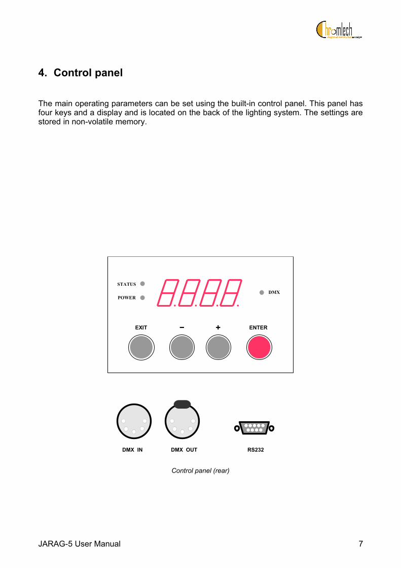
4. Control panel
The main operating parameters can be set using the built-in control panel. This panel has four keys and a display and is located on the back of the lighting system. The settings are stored in non-volatile memory.
Control panel (rear)
JARAG-5 User Manual 7
. .. .EXIT ENTER
POWER
STATUS
DMX
JARAG - 5WARNING : lamps are hotFor professional use onlyDisconnect power before servicing the equipment
230 V - 25x MAX 75W = 1875 W - 8,2 AMin distance to lighted object : 1 mMin distance to flammable objects : 1 mMax ambient temperature : 40°CMax exterior surface temperature : 60°C
− +
Made in France
DMX IN DMX OUT RS232

Connectors
DMX INFunction DMX 512 inputType XLR 5 pin malePinout 1: Shield (ground)
2: DMX – (primary data – )3: DMX + (primary data + )4: Not connected5: Not connected
DMX OUTFunction DMX 512 outputType XLR 5 pin femalePinout 1: Shield (ground)
2: DMX – (primary data – )3: DMX + (primary data + )4: Not connected5: Not connected
RS232Function SubD 9 pin femaleType Serial link to PCPinout 1: Not connected
2: TX (output)3: RX (input)4: DTR (input)5: Ground6: Not connected7: Not connected8 Not connected9: Not connected
8 JARAG-5 User Manual

Indicators
POWEROff No power or fuse blownGreen Power on
STATUSOff Normal operationRed Malfunction. Maintenance required.
DMXOff No DMX signalGreen DMX signal OKGreen flashing orange
Occasional DMX errors: poor quality DMX signalCheck the connections and signal integrity.
Red DMX connection fault or polarity inversion: DMX signal not usable
JARAG-5 User Manual 9
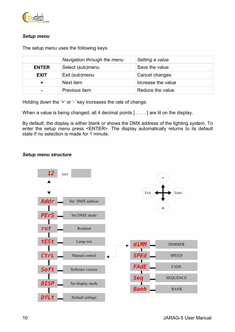
Setup menu
The setup menu uses the following keys.
Navigation through the menu Setting a valueENTER Select (sub)menu Save the value
EXIT Exit (sub)menu Cancel changes+ Next item Increase the value- Previous item Reduce the value
Holding down the ‘+’ or ‘-‘ key increases the rate of change.
When a value is being changed, all 4 decimal points [ . . . . ] are lit on the display.
By default, the display is either blank or shows the DMX address of the lighting system. To enter the setup menu press <ENTER>. The display automatically returns to its default state if no selection is made for 1 minute.
Setup menu structure
10 JARAG-5 User Manual
Set DMX address
Lamp test
Set DMX mode
Addr
PErS
tESt DIMMER
CtrL
Set display modeDISP
Default settingsDfLt
diMM
Manual control SPEEDSPEd
FADEFAdE
BANKBanh
SEQUENCESeq
-
+
EnterExit
12 (or)
Software versionSoft
Rotationrot

AddrFunction Sets DMX addressValue The value is the first DMX channel for the lighting system.
Minimum = 1Maximum = 512 (nominal)Maximum value for 6 channel personality = 507Maximum value for 25 channel personality = 488Maximum value for 31 channel personality = 482
PersFunction Sets DMX personalityValue 6 ch = 6 DMX channels (using internal sequences)
25ch = 25 DMX channels (direct array addressing)31ch = 31 DMX channels (internal sequences + array, using HTP)See chapter 5 for the assignment of the channels
RotFunction Sets rotation of the lighting systemValue = no rotation
= 90° rotation= 180° rotation= 270° rotation
TestFunction Lights all the lamps for testingValue Test selected = all the lamps are lit at low power
CtrlFunction Manual control of the lighting system using 5 channelsValue Dimm = 'Dimmer' channel (intensity for the sequence)
Sped = 'Speed' channel (speed or step selection for the sequence)Fade = 'Fade' channel (cross-fade and LV halogen emulation)Seq = 'Sequence' channel (selects the sequence)Banh = 'Bank' channel (selects the sequence bank)
DispFunction Sets the default display modeValue On = the display shows the DMS of the lighting system continuously
Off = the display shows the DMX address and goes off after about 1 minute
DfltFunction Restores the default settingsValue This sets the following values:
DMX address = 1, personality = 6 channels, rotation = 0°, display = On
JARAG-5 User Manual 11
UPUP
UP
U P

5. DMX control
Three different DMX personalities are available.
6 channel personality (sequences)
6 channel personality is used to replay sequences programmed in the built-in sequencer.
Channel 1 Intensity0 %to100%
Off
Full OnFlash Full On, starting from the first step of the sequence
Channel 2 Speed Step0% Off3%to50%
Fast
Slow50%to95%
Step 1
Step 32100% (Flash)
Synchronise sequence to first step
Channel 3 Cross-fade Low-voltage lamp effect0%to50%
Fast
SlowOff
50%to100%
Slow
FastOn
12 JARAG-5 User Manual

Channel 4 reflection Rotation 0 ... 12% None 013 ... 25% Vertical 026 ... 37% Horizontal 038 ... 50% Vertical + horizontal 051 ... 62% None 90°63 ... 75% Vertical 90°76 ... 87% Horizontal 90°88...100% Vertical + horizontal 90°
Channel 5 Sequence selection0%to100%
Sequence 1
Sequence 16
Channel 6 Sequence bank selection0%to100%
Bank 1
Bank 16
JARAG-5 User Manual 13

25 channel personality (matrix)
The intensity of each lamp is directly controlled by a DMX channel as for a conventional dimmer and the built-in sequencer is disabled.
The following schematic shows the channel assignments for the lamps.
Channel 1 to 25 Intensity0%to100%
Off
Full On
31 channel personality (dual)
Each lamp is controlled simultaneously by the built-in sequencer (6 channel mode) and individually as an array (25 channel mode).The lighting system calculates the intensity from the two modes using HTP (Highest takes Precedence) for each lamp individually.
Channel 1 to 6 Sequence control (6 channel mode)Channel 1Channel 2Channel 3Channel 4Channel 5Channel 6
IntensitySpeed / stepCross-fade / low-voltage lamp effectRotation / reflectionSequence Sequence bank
Channel 7 to 31 Matrix control (25 channel mode)Channel 7 ... Channel 31
Lamp 1
Lamp 25
14 JARAG-5 User Manual
1 2 3 4 5
6 7 8 9 10
11 12 13 14 15
16 17 18 19 20
21 22 23 24 25

6. Programming
The sequences are programmed using the "Jarag Control Center".This program can be downloaded from www.chromlech.com
Further information can be found in the program documentation.
JARAG-5 User Manual 15
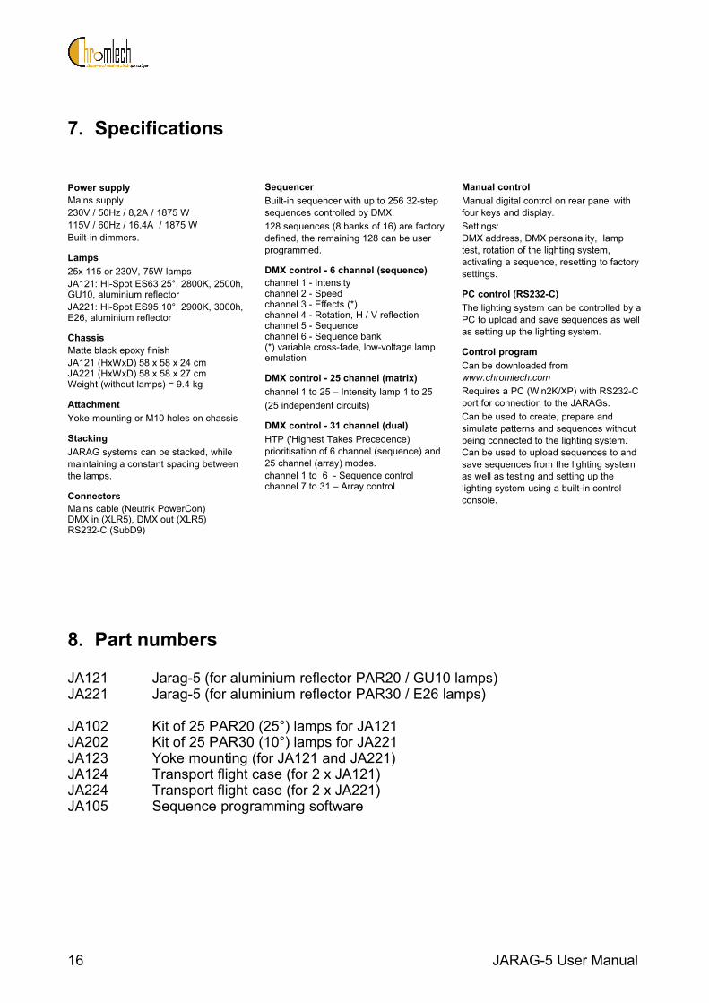
7. Specifications
Power supplyMains supply230V / 50Hz / 8,2A / 1875 W115V / 60Hz / 16,4A / 1875 WBuilt-in dimmers.
Lamps25x 115 or 230V, 75W lamps JA121: Hi-Spot ES63 25°, 2800K, 2500h, GU10, aluminium reflectorJA221: Hi-Spot ES95 10°, 2900K, 3000h, E26, aluminium reflector
ChassisMatte black epoxy finishJA121 (HxWxD) 58 x 58 x 24 cmJA221 (HxWxD) 58 x 58 x 27 cmWeight (without lamps) = 9.4 kg
AttachmentYoke mounting or M10 holes on chassis
StackingJARAG systems can be stacked, while maintaining a constant spacing between the lamps.
ConnectorsMains cable (Neutrik PowerCon)DMX in (XLR5), DMX out (XLR5)RS232-C (SubD9)
SequencerBuilt-in sequencer with up to 256 32-step sequences controlled by DMX.128 sequences (8 banks of 16) are factory defined, the remaining 128 can be user programmed.
DMX control - 6 channel (sequence)channel 1 - Intensitychannel 2 - Speedchannel 3 - Effects (*)channel 4 - Rotation, H / V reflectionchannel 5 - Sequencechannel 6 - Sequence bank(*) variable cross-fade, low-voltage lamp emulation
DMX control - 25 channel (matrix)channel 1 to 25 – Intensity lamp 1 to 25(25 independent circuits)
DMX control - 31 channel (dual)HTP ('Highest Takes Precedence) prioritisation of 6 channel (sequence) and 25 channel (array) modes.channel 1 to 6 - Sequence control channel 7 to 31 – Array control
Manual controlManual digital control on rear panel with four keys and display.Settings:DMX address, DMX personality, lamp test, rotation of the lighting system, activating a sequence, resetting to factory settings.
PC control (RS232-C)The lighting system can be controlled by a PC to upload and save sequences as well as setting up the lighting system.
Control programCan be downloaded from www.chromlech.comRequires a PC (Win2K/XP) with RS232-C port for connection to the JARAGs.Can be used to create, prepare and simulate patterns and sequences without being connected to the lighting system. Can be used to upload sequences to and save sequences from the lighting system as well as testing and setting up the lighting system using a built-in control console.
8. Part numbers
JA121 Jarag-5 (for aluminium reflector PAR20 / GU10 lamps)JA221 Jarag-5 (for aluminium reflector PAR30 / E26 lamps)
JA102 Kit of 25 PAR20 (25°) lamps for JA121JA202 Kit of 25 PAR30 (10°) lamps for JA221JA123 Yoke mounting (for JA121 and JA221)JA124 Transport flight case (for 2 x JA121)JA224 Transport flight case (for 2 x JA221)JA105 Sequence programming software
16 JARAG-5 User Manual

Sequence table
JARAG-5 User Manual 17
(page left intentionally blank)
18 JARAG-5 User Manual

JAR
AG
-5S
eque
nce
Tab
le
[28/
12/2
005
- V
2_1.
pdf]

JAR
AG
- 5
28/1
2/20
05-
V2_
1.pd
f
%S
EQ
Ban
k F
act1
Chr
omle
ch
12
34
56
78
910
1112
1314
1516
1718
1920
2122
2324
2526
2728
2930
3132
31
92
153
214
285
346
407
468
539
5910
6511
7112
7813
8414
9015
9616

JAR
AG
- 5
28/1
2/20
05-
V2_
1.pd
f
%S
EQ
Ban
k F
act2
Chr
omle
ch
12
34
56
78
910
1112
1314
1516
1718
1920
2122
2324
2526
2728
2930
3132
31
92
153
214
285
346
407
468
539
5910
6511
7112
7813
8414
9015
9616

JAR
AG
- 5
28/1
2/20
05-
V2_
1.pd
f
%S
EQ
Ban
k F
act3
Chr
omle
ch
12
34
56
78
910
1112
1314
1516
1718
1920
2122
2324
2526
2728
2930
3132
31
92
153
214
285
346
407
468
539
5910
6511
7112
7813
8414
9015
9616
JAR
AG
- 5
28/1
2/20
05-
V2_
1.pd
f
%S
EQ
Ban
k F
act4
Chr
omle
ch
12
34
56
78
910
1112
1314
1516
1718
1920
2122
2324
2526
2728
2930
3132
31
92
153
214
285
346
407
468
539
5910
6511
7112
7813
8414
9015
9616
JAR
AG
- 5
28/1
2/20
05-
V2_
1.pd
f
%S
EQ
Ban
k F
act5
Chr
omle
ch
12
34
56
78
910
1112
1314
1516
1718
1920
2122
2324
2526
2728
2930
3132
31
92
153
214
285
346
407
468
539
5910
6511
7112
7813
8414

JAR
AG
- 5
28/1
2/20
05-
V2_
1.pd
f
%S
EQ
Ban
k F
act6
Chr
omle
ch
12
34
56
78
910
1112
1314
1516
1718
1920
2122
2324
2526
2728
2930
3132
31
92
153
214
285
346
407
468
539
5910
6511
7112
7813
8414
9015
9616
JAR
AG
- 5
28/1
2/20
05-
V2_
1.pd
f
%S
EQ
Ban
k F
act7
Chr
omle
ch
12
34
56
78
910
1112
1314
1516
1718
1920
2122
2324
2526
2728
2930
3132
31
92
153
214
285
346
407
468
539
5910
6511

JAR
AG
- 5
28/1
2/20
05-
V2_
1.pd
f
%S
EQ
Ban
k F
act8
Chr
omle
ch
12
34
56
78
910
1112
1314
1516
1718
1920
2122
2324
2526
2728
2930
3132
31
92
153
214
285
346
407
468