Monday March 4, 2013 Introducing Current and Direct Current Circuits.
Upload
rolf-carsonCategory
view
228download
1
January 30, 2008
Introducing CurrentandDirect Current Circuits

Current
Current is defined as the flow of positive charge.I = Q/t I: current in Amperes or Amps (A) Q: charge in Coulombs (C) t: time in seconds

In a normal electrical circuit, it is the electrons that carry the charge.
So if the electrons move this way, which way does the current move?
Charge carriers
e-
I

Circuit components
Cell
Battery

Circuit components
Light bulb
Wire
Switch

Circuit components
V Voltmeter
Ohmmeter
Ammeter
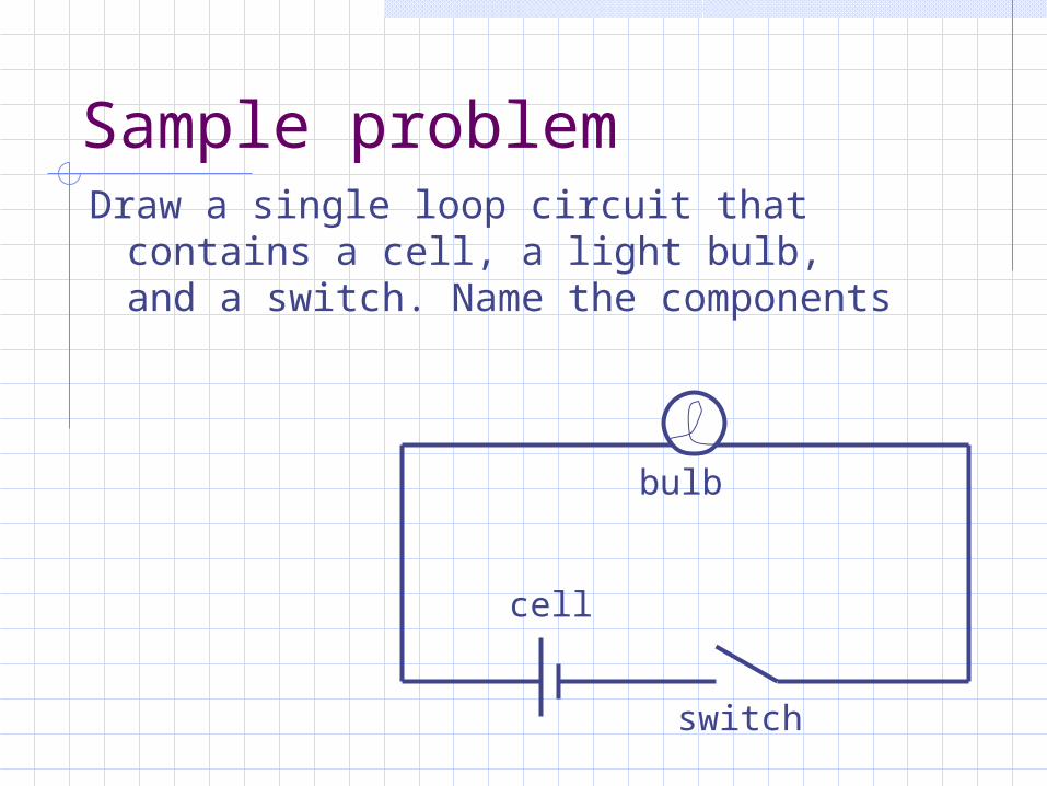
Sample problemDraw a single loop circuit that contains
a cell, a light bulb, and a switch. Name the components
bulb
cell
switch
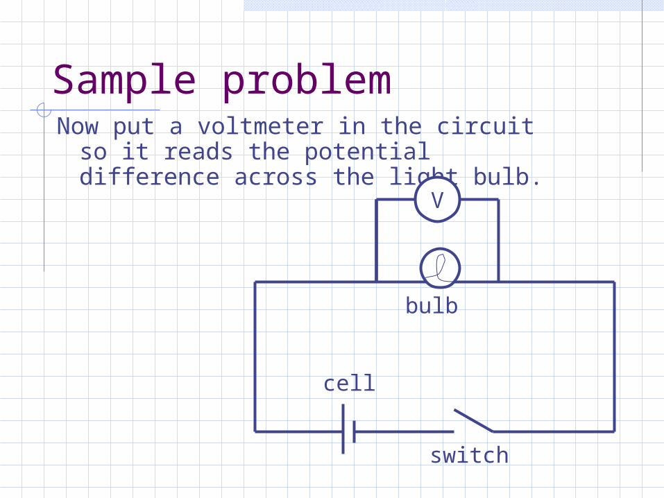
Sample problemNow put a voltmeter in the circuit so it
reads the potential difference across the light bulb.
bulb
cell
switch
V

Series arrangement of components
Series components are put together so that all the current must go through each one
Three bulbs in series all have the same current.
I

Parallel arrangement of components
Parallel components are put together so that the current divides, and each component gets only a fraction of it.
Three bulbs in parallel
I
1/3 I
1/3 I
1/3 I 1/3 I
1/3 I
1/3 I
I
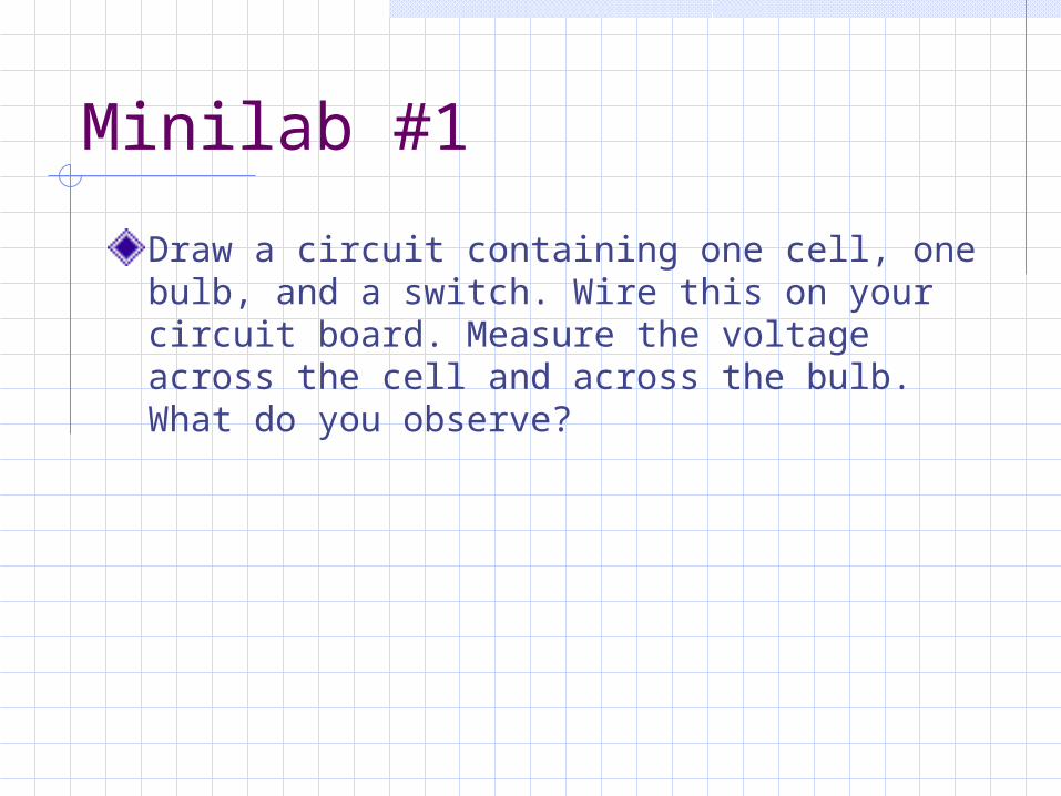
Minilab #1
Draw a circuit containing one cell, one bulb, and a switch. Wire this on your circuit board. Measure the voltage across the cell and across the bulb. What do you observe?
January 31, 2008
Resistance, Resistivity, and Ohm’s Law

Minilab #2
Draw a circuit containing two cells in series, one bulb, and a switch. Wire this on your circuit board. What do you observe happens to the bulb? Measure the voltage across the battery and across the bulb. What do you observe?

Minilab #3Draw a circuit containing two cells in series, two bulbs in series, and a switch. Wire this on your circuit board. What do you observe happens to the bulbs when you unscrew one of them? Measure the voltage across the battery and across each bulb. What do you observe?
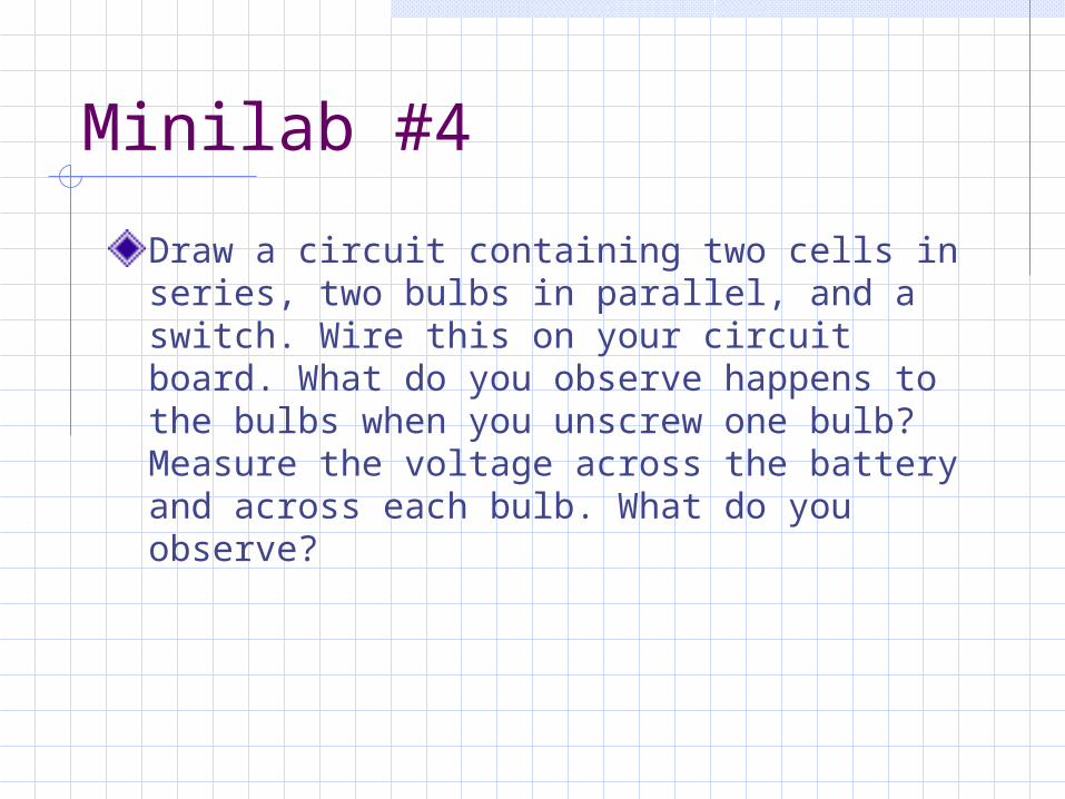
Minilab #4
Draw a circuit containing two cells in series, two bulbs in parallel, and a switch. Wire this on your circuit board. What do you observe happens to the bulbs when you unscrew one bulb? Measure the voltage across the battery and across each bulb. What do you observe?
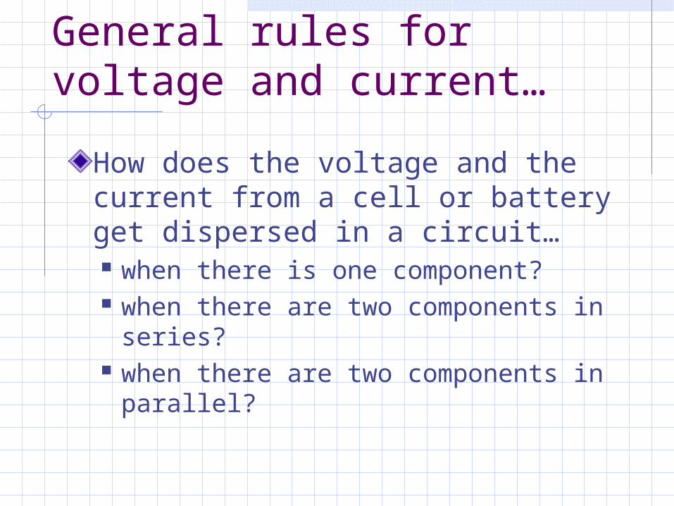
General rules for voltage and current…
How does the voltage and the current from a cell or battery get dispersed in a circuit… when there is one component? when there are two components in
series? when there are two components in
parallel?
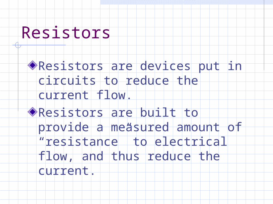
Resistors
Resistors are devices put in circuits to reduce the current flow.Resistors are built to provide a measured amount of “resistance” to electrical flow, and thus reduce the current.

Circuit components
Resistor

Resitance, R
Resistance depends on resistivity and on geometry of the resistor.R = L/A : resistivity ( m) L: length of resistor (m) A: cross sectional area of resistor
(m2)
Unit of resistance: Ohms ()

Ohm’s Law
Resistance in a component in a circuit causes potential to drop according to the equation:V = IR V: potential drop (Volts) I: current (Amperes) R: resistance (Ohms)

Friday, February 1, 2008
Power in Electrical Circuits
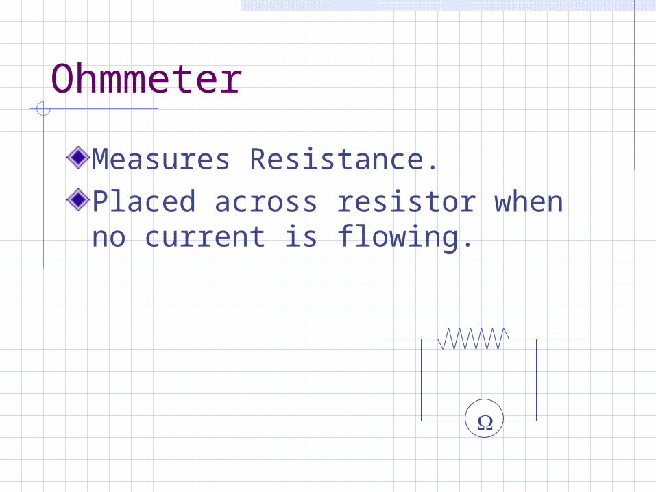
Ohmmeter
Measures Resistance.Placed across resistor when no current is flowing.

MiniLab #5
Set up your digital multi-meter to measure resistance. Measure the resistance of the each light bulb on your board. Record the results.Wire the three bulbs together in series, and draw this arrangement. Measure the resistance of all three bulbs together in the series circuit. How does this compare to the resistance of the individual bulbs?Wire the three bulbs together in parallel, and draw this arrangement. Measure the resistance of the parallel arrangement. How does this compare to the resistance of the individual bulbs?

MiniLab #6
Measure the resistance of the different resistors you have been given. Make a table and record the color of the first three bands (ignore the gold band) and the resistance associated with the band color. See if you can figure out the code.

Resistor codes
Resistor color codes are read as follows: http://www.uoguelph.ca/~antoon/gad
gets/resistors/resistor.htm
It is helpful to know this code, but you will not be required to memorize it.
Monday, February 4, 2008
Power and Equivalent Resistance

Power in General
P = W/tP = E/tUnits Watts Joules/second
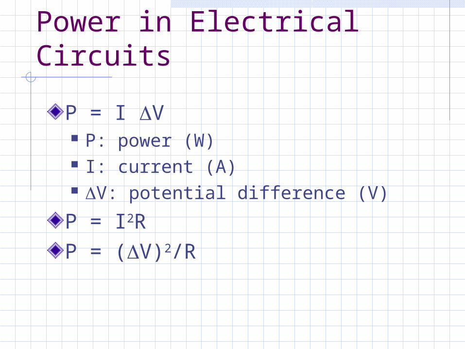
Power in Electrical Circuits
P = I V P: power (W) I: current (A) V: potential difference (V)
P = I2RP = (V)2/R

Resistors in circuits
Resistors can be placed in circuits in a variety of arrangements in order to control the current.Arranging resistors in series increases the resistance and causes the current to be reduced.Arranging resistors in parallel reduces the resistance and causes the current to increase.The overall resistance of a specific grouping of resistors is referred to as the equivalent resistance.

Resistors in series
R1 R2 R3
Req = R1 + R2 + R3
Req = Ri

Resistors in parallelR1
R2
R3
1/Req = 1/R1 + 1/R2 + 1/R3
1/Req = 1/Ri )
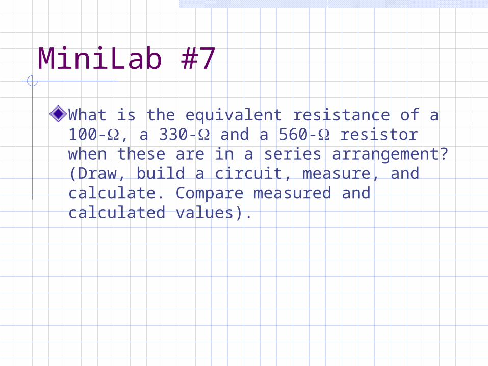
MiniLab #7
What is the equivalent resistance of a 100-, a 330- and a 560- resistor when these are in a series arrangement? (Draw, build a circuit, measure, and calculate. Compare measured and calculated values).

Minilab #8
What is the equivalent resistance of a 100-, a 330- and a 560- resistor when these are in a parallel arrangement? (Draw, build a circuit, measure, and calculate. Compare measured and calculated values.)
Tuesday, February 5, 2008
Combination CircuitsKirchoff’s Rules

Minilab #9Draw and build an arrangement of resistance that uses both parallel and series arrangements for 5 or 6 resistors in your kit. Calculate and then measure the equivalent resistance. Compare the values.

Kirchoff’s 1st Rule
Kirchoff’s 1st rule is also called the “junction rule”.The sum of the currents entering a junction equals the sum of the currents leaving the junction.This rule is based upon conservation of charge.

Sample problem
Find the current I4 (magnitude and direction).
4.0 A
3.0 A
1.5 A
I4
Kirchoff’s 2nd Rule
Kirchoff’s 2nd rule is also referred to as the “loop rule”.The net change in electrical potential in going around one complete loop in a circuit is equal to zero.This rule is based upon conservation of energy.

Sample problemUse the loop rule to determine the potential drop across the light bulb.
1.5 V 9.0 V
V
2.0 V
V
3.0 V

Minilab #10Draw and build a double loop circuit and verify Kirchoff’s rules for that double loop circuit.
Ohm’s Law LabUsing the resistors provided, design an experiment to create a graph such that the terminal voltage of the cell will appear as the slope of a best fit line. You must use 8 unique resistance values in your experiment.