January 2012 IC-CAP 2012 - Keysightedadownload.software.keysight.com/eedl/iccap/2012_01/pdf/... ·...
128
Transcript of January 2012 IC-CAP 2012 - Keysightedadownload.software.keysight.com/eedl/iccap/2012_01/pdf/... ·...

IC-CAP Wafer Professional (WaferPro)
1
IC-CAP 2012.01January 2012
IC-CAP Wafer Professional (WaferPro)
IC-CAP Wafer Professional (WaferPro)
2
© Agilent Technologies, Inc. 2000-20113501 Stevens Creek Blvd., Santa Clara, CA 95052 USANo part of this documentation may be reproduced in any form or by any means (includingelectronic storage and retrieval or translation into a foreign language) without prioragreement and written consent from Agilent Technologies, Inc. as governed by UnitedStates and international copyright laws.
Acknowledgments
UNIX ® is a registered trademark of the Open Group.MS-DOS ®, Windows ®, and MS Windows ® are U.S. registered trademarks of MicrosoftCorporation.Pentium ® is a U.S. registered trademark of Intel Corporation.PostScript® is a trademark of Adobe Systems Incorporated.Java™ is a U.S. trademark of Sun Microsystems, Inc.Mentor Graphics is a trademark of Mentor Graphics Corporation in the U.S. and othercountries.Qt Version 4.6Qt NoticeThe Qt code was modified. Used by permission.Qt CopyrightQt Version 4.6, Copyright (c) 2009 by Nokia Corporation. All Rights Reserved.Qt License Your use or distribution of Qt or any modified version of Qt implies that youagree to this License. This library is free software; you can redistribute it and/or modify itunder the terms of the GNU Lesser General Public License as published by the FreeSoftware Foundation; either version 2.1 of the License, or (at your option) any laterversion. This library is distributed in the hope that it will be useful, but WITHOUT ANYWARRANTY; without even the implied warranty of MERCHANTABILITY or FITNESS FOR APARTICULAR PURPOSE. See the GNU Lesser General Public License for more details. Youshould have received a copy of the GNU Lesser General Public License along with thislibrary; if not, write to the Free Software Foundation, Inc., 51 Franklin St, Fifth Floor,Boston, MA 02110-1301 USA Permission is hereby granted to use or copy this programunder the terms of the GNU LGPL, provided that the Copyright, this License, and theAvailability of the original version is retained on all copies. User documentation of anycode that uses this code or any modified version of this code must cite the Copyright, thisLicense, the Availability note, and "Used by permission." Permission to modify the codeand to distribute modified code is granted, provided the Copyright, this License, and theAvailability note are retained, and a notice that the code was modified is included.Qt Availability http://www.qtsoftware.com/downloadsPatches Applied to Qt can be found in the installation at:$HPEESOF_DIR/prod/licenses/thirdparty/qt/patches.You may also contact Brian Buchanan at Agilent Inc. at [email protected] formore information. For details see:http://bmaster.soco.agilent.com/mw/Qt_License_Information
Errata The IC-CAP product may contain references to "HP" or "HPEESOF" such as in filenames and directory names. The business entity formerly known as "HP EEsof" is now partof Agilent Technologies and is known as "Agilent EEsof." To avoid broken functionality andto maintain backward compatibility for our customers, we did not change all the namesand labels that contain "HP" or "HPEESOF" references.
Warranty The material contained in this documentation is provided "as is", and is subjectto being changed, without notice, in future editions. Further, to the maximum extentpermitted by applicable law, Agilent disclaims all warranties, either express or implied,with regard to this manual and any information contained herein, including but not limitedto the implied warranties of merchantability and fitness for a particular purpose. Agilentshall not be liable for errors or for incidental or consequential damages in connection with
IC-CAP Wafer Professional (WaferPro)
3
the furnishing, use, or performance of this document or of any information containedherein. Should Agilent and the user have a separate written agreement with warrantyterms covering the material in this document that conflict with these terms, the warrantyterms in the separate agreement shall control.
Technology Licenses The hardware and/or software described in this document arefurnished under a license and may be used or copied only in accordance with the terms ofsuch license.
Restricted Rights Legend U.S. Government Restricted Rights. Software and technicaldata rights granted to the federal government include only those rights customarilyprovided to end user customers. Agilent provides this customary commercial license inSoftware and technical data pursuant to FAR 12.211 (Technical Data) and 12.212(Computer Software) and, for the Department of Defense, DFARS 252.227-7015(Technical Data - Commercial Items) and DFARS 227.7202-3 (Rights in CommercialComputer Software or Computer Software Documentation).
IC-CAP Wafer Professional (WaferPro)
4
Before You Begin Using WaferPro . . . . . . . . . . . . . . . . . . . . . . . . . . . . . . . . . . . . . . . . . . . . . 5 WaferPro Project Structure . . . . . . . . . . . . . . . . . . . . . . . . . . . . . . . . . . . . . . . . . . . . . . . . . 7 WaferPro Project Environment . . . . . . . . . . . . . . . . . . . . . . . . . . . . . . . . . . . . . . . . . . . . . . . 13
Using the WaferPro Project Interface . . . . . . . . . . . . . . . . . . . . . . . . . . . . . . . . . . . . . . . . . 14 Understanding the Project View . . . . . . . . . . . . . . . . . . . . . . . . . . . . . . . . . . . . . . . . . . . . 23 Configuring a WaferPro Project . . . . . . . . . . . . . . . . . . . . . . . . . . . . . . . . . . . . . . . . . . . . . 25 Defining Wafer Layout Specification (Wafer Map) . . . . . . . . . . . . . . . . . . . . . . . . . . . . . . . . 34 Block and Subsites Definition . . . . . . . . . . . . . . . . . . . . . . . . . . . . . . . . . . . . . . . . . . . . . . 39 Device Info . . . . . . . . . . . . . . . . . . . . . . . . . . . . . . . . . . . . . . . . . . . . . . . . . . . . . . . . . . . 41 Test Plan Definition . . . . . . . . . . . . . . . . . . . . . . . . . . . . . . . . . . . . . . . . . . . . . . . . . . . . . 45 Target Dies . . . . . . . . . . . . . . . . . . . . . . . . . . . . . . . . . . . . . . . . . . . . . . . . . . . . . . . . . . . 47 Target Devices . . . . . . . . . . . . . . . . . . . . . . . . . . . . . . . . . . . . . . . . . . . . . . . . . . . . . . . . 49 Measurement Conditions . . . . . . . . . . . . . . . . . . . . . . . . . . . . . . . . . . . . . . . . . . . . . . . . . 53 Characterization Steps . . . . . . . . . . . . . . . . . . . . . . . . . . . . . . . . . . . . . . . . . . . . . . . . . . . 55 Sequence Control . . . . . . . . . . . . . . . . . . . . . . . . . . . . . . . . . . . . . . . . . . . . . . . . . . . . . . 57 Test Plan Run . . . . . . . . . . . . . . . . . . . . . . . . . . . . . . . . . . . . . . . . . . . . . . . . . . . . . . . . . 59 Single Run and Debug . . . . . . . . . . . . . . . . . . . . . . . . . . . . . . . . . . . . . . . . . . . . . . . . . . . 61
Getting Started with WaferPro . . . . . . . . . . . . . . . . . . . . . . . . . . . . . . . . . . . . . . . . . . . . . . . 64 Starting WaferPro . . . . . . . . . . . . . . . . . . . . . . . . . . . . . . . . . . . . . . . . . . . . . . . . . . . . . . 65 Managing WaferPro Projects . . . . . . . . . . . . . . . . . . . . . . . . . . . . . . . . . . . . . . . . . . . . . . . 66 An Example WaferPro Session . . . . . . . . . . . . . . . . . . . . . . . . . . . . . . . . . . . . . . . . . . . . . . 69 Preparing For Real Measurements . . . . . . . . . . . . . . . . . . . . . . . . . . . . . . . . . . . . . . . . . . . 75
About WaferPro Measurement and Routine Files . . . . . . . . . . . . . . . . . . . . . . . . . . . . . . . . . . . 79 About Measurement Routine File . . . . . . . . . . . . . . . . . . . . . . . . . . . . . . . . . . . . . . . . . . . . 80 About WaferPro Routine . . . . . . . . . . . . . . . . . . . . . . . . . . . . . . . . . . . . . . . . . . . . . . . . . . 81 Creating a Routine for WaferPro . . . . . . . . . . . . . . . . . . . . . . . . . . . . . . . . . . . . . . . . . . . . 82 PEL Functions . . . . . . . . . . . . . . . . . . . . . . . . . . . . . . . . . . . . . . . . . . . . . . . . . . . . . . . . . 86 Test Plan Execution Flow . . . . . . . . . . . . . . . . . . . . . . . . . . . . . . . . . . . . . . . . . . . . . . . . . 90 Controlling WaferPro via IC-CAP PEL . . . . . . . . . . . . . . . . . . . . . . . . . . . . . . . . . . . . . . . . . 91
About WaferPro Driver File . . . . . . . . . . . . . . . . . . . . . . . . . . . . . . . . . . . . . . . . . . . . . . . . . . 93 Working with Configuration and Output Files . . . . . . . . . . . . . . . . . . . . . . . . . . . . . . . . . . . . . 95 Using WaferPro with Parametric Test System and Auto Probers . . . . . . . . . . . . . . . . . . . . . . . . 102
IC-CAP Wafer Professional (WaferPro)
5
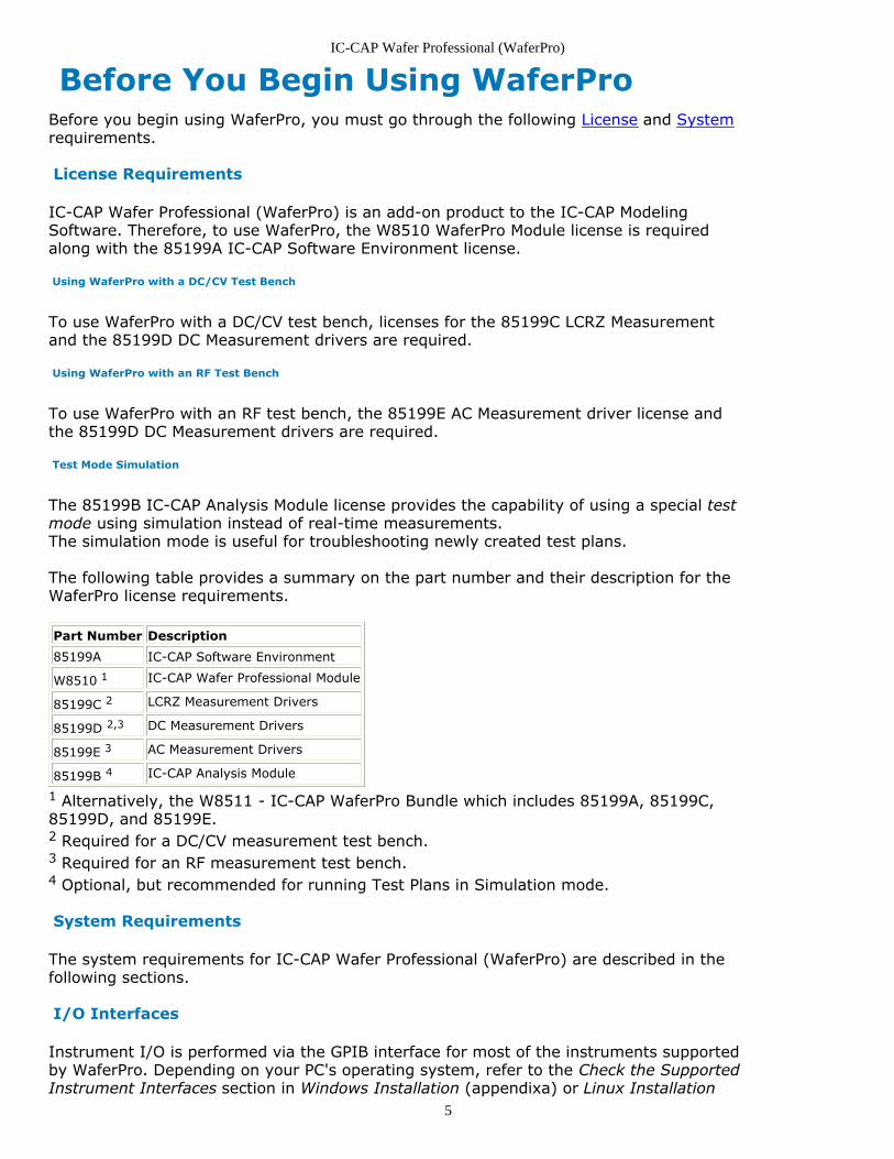
Before You Begin Using WaferProBefore you begin using WaferPro, you must go through the following License and Systemrequirements.
License Requirements
IC-CAP Wafer Professional (WaferPro) is an add-on product to the IC-CAP ModelingSoftware. Therefore, to use WaferPro, the W8510 WaferPro Module license is requiredalong with the 85199A IC-CAP Software Environment license.
Using WaferPro with a DC/CV Test Bench
To use WaferPro with a DC/CV test bench, licenses for the 85199C LCRZ Measurementand the 85199D DC Measurement drivers are required.
Using WaferPro with an RF Test Bench
To use WaferPro with an RF test bench, the 85199E AC Measurement driver license andthe 85199D DC Measurement drivers are required.
Test Mode Simulation
The 85199B IC-CAP Analysis Module license provides the capability of using a special testmode using simulation instead of real-time measurements.The simulation mode is useful for troubleshooting newly created test plans.
The following table provides a summary on the part number and their description for theWaferPro license requirements.
Part Number Description
85199A IC-CAP Software Environment
W8510 1 IC-CAP Wafer Professional Module
85199C 2 LCRZ Measurement Drivers
85199D 2,3 DC Measurement Drivers
85199E 3 AC Measurement Drivers
85199B 4 IC-CAP Analysis Module
1 Alternatively, the W8511 - IC-CAP WaferPro Bundle which includes 85199A, 85199C,85199D, and 85199E.2 Required for a DC/CV measurement test bench.3 Required for an RF measurement test bench.4 Optional, but recommended for running Test Plans in Simulation mode.
System Requirements
The system requirements for IC-CAP Wafer Professional (WaferPro) are described in thefollowing sections.
I/O Interfaces
Instrument I/O is performed via the GPIB interface for most of the instruments supportedby WaferPro. Depending on your PC's operating system, refer to the Check the SupportedInstrument Interfaces section in Windows Installation (appendixa) or Linux Installation
IC-CAP Wafer Professional (WaferPro)
6
(appendixa) sections for further details on supported interfaces.
A special optical interface is used with the Agilent 407x and 408x Series ParametricTesters to control the test head using a Linux workstation. These interfaces are onlyavailable for use with Agilent Parametric testers.
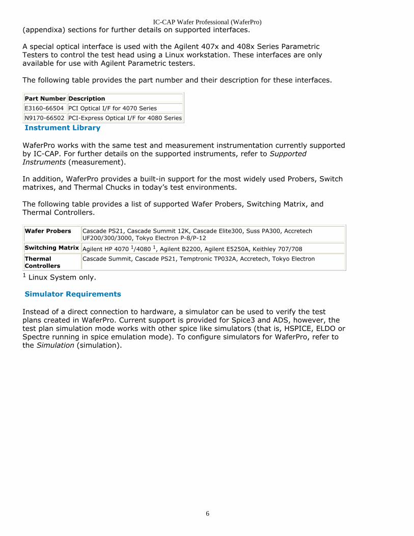
The following table provides the part number and their description for these interfaces.
Part Number Description
E3160-66504 PCI Optical I/F for 4070 Series
N9170-66502 PCI-Express Optical I/F for 4080 Series
Instrument Library
WaferPro works with the same test and measurement instrumentation currently supportedby IC-CAP. For further details on the supported instruments, refer to SupportedInstruments (measurement).
In addition, WaferPro provides a built-in support for the most widely used Probers, Switchmatrixes, and Thermal Chucks in today’s test environments.
The following table provides a list of supported Wafer Probers, Switching Matrix, andThermal Controllers.
Wafer Probers Cascade PS21, Cascade Summit 12K, Cascade Elite300, Suss PA300, AccretechUF200/300/3000, Tokyo Electron P-8/P-12
Switching Matrix Agilent HP 4070 1/4080 1, Agilent B2200, Agilent E5250A, Keithley 707/708
ThermalControllers
Cascade Summit, Cascade PS21, Temptronic TP032A, Accretech, Tokyo Electron
1 Linux System only.
Simulator Requirements
Instead of a direct connection to hardware, a simulator can be used to verify the testplans created in WaferPro. Current support is provided for Spice3 and ADS, however, thetest plan simulation mode works with other spice like simulators (that is, HSPICE, ELDO orSpectre running in spice emulation mode). To configure simulators for WaferPro, refer tothe Simulation (simulation).
IC-CAP Wafer Professional (WaferPro)
7
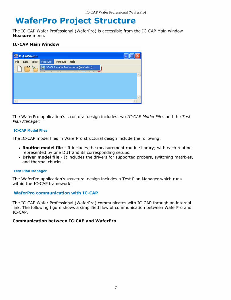
WaferPro Project StructureThe IC-CAP Wafer Professional (WaferPro) is accessible from the IC-CAP Main windowMeasure menu.
IC-CAP Main Window
The WaferPro application’s structural design includes two IC-CAP Model Files and the TestPlan Manager.
IC-CAP Model Files
The IC-CAP model files in WaferPro structural design include the following:
Routine model file - It includes the measurement routine library; with each routinerepresented by one DUT and its corresponding setups.Driver model file - It includes the drivers for supported probers, switching matrixes,and thermal chucks.
Test Plan Manager
The WaferPro application’s structural design includes a Test Plan Manager which runswithin the IC-CAP framework.
WaferPro communication with IC-CAP
The IC-CAP Wafer Professional (WaferPro) communicates with IC-CAP through an internallink. The following figure shows a simplified flow of communication between WaferPro andIC-CAP.
Communication between IC-CAP and WaferPro
IC-CAP Wafer Professional (WaferPro)
8
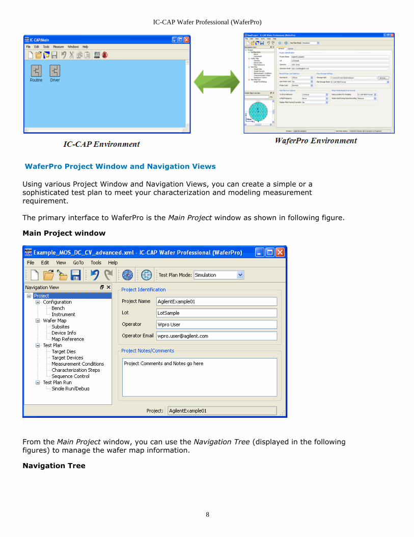
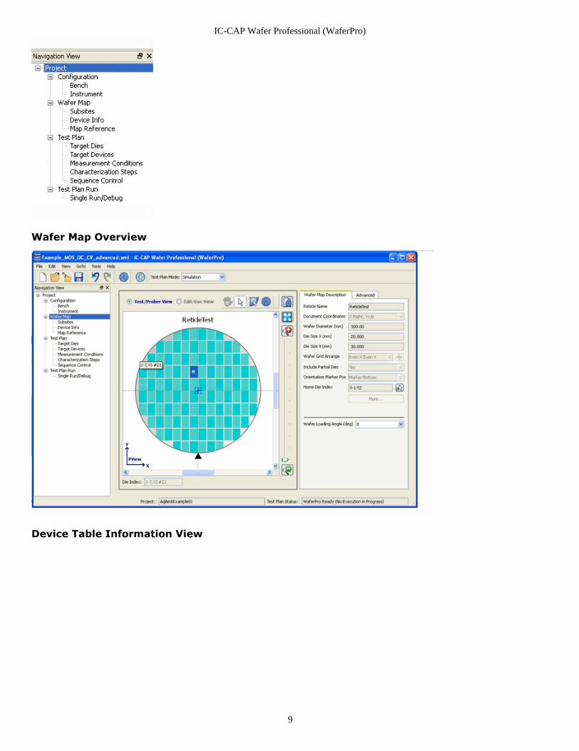
WaferPro Project Window and Navigation Views
Using various Project Window and Navigation Views, you can create a simple or asophisticated test plan to meet your characterization and modeling measurementrequirement.
The primary interface to WaferPro is the Main Project window as shown in following figure.
Main Project window
From the Main Project window, you can use the Navigation Tree (displayed in the followingfigures) to manage the wafer map information.
Navigation Tree
IC-CAP Wafer Professional (WaferPro)
9
Wafer Map Overview
Device Table Information View
IC-CAP Wafer Professional (WaferPro)
10
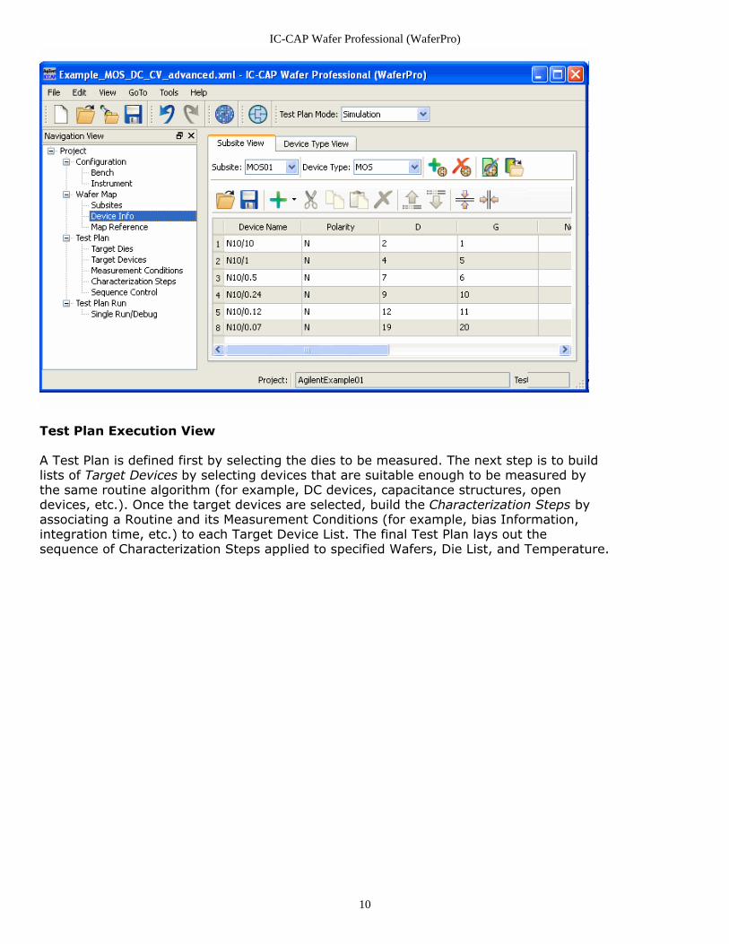
Test Plan Execution View
A Test Plan is defined first by selecting the dies to be measured. The next step is to buildlists of Target Devices by selecting devices that are suitable enough to be measured bythe same routine algorithm (for example, DC devices, capacitance structures, opendevices, etc.). Once the target devices are selected, build the Characterization Steps byassociating a Routine and its Measurement Conditions (for example, bias Information,integration time, etc.) to each Target Device List. The final Test Plan lays out thesequence of Characterization Steps applied to specified Wafers, Die List, and Temperature.
IC-CAP Wafer Professional (WaferPro)
11
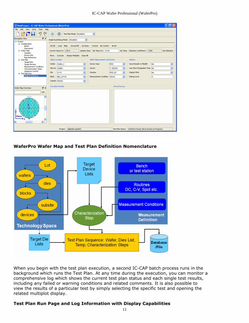
WaferPro Wafer Map and Test Plan Definition Nomenclature
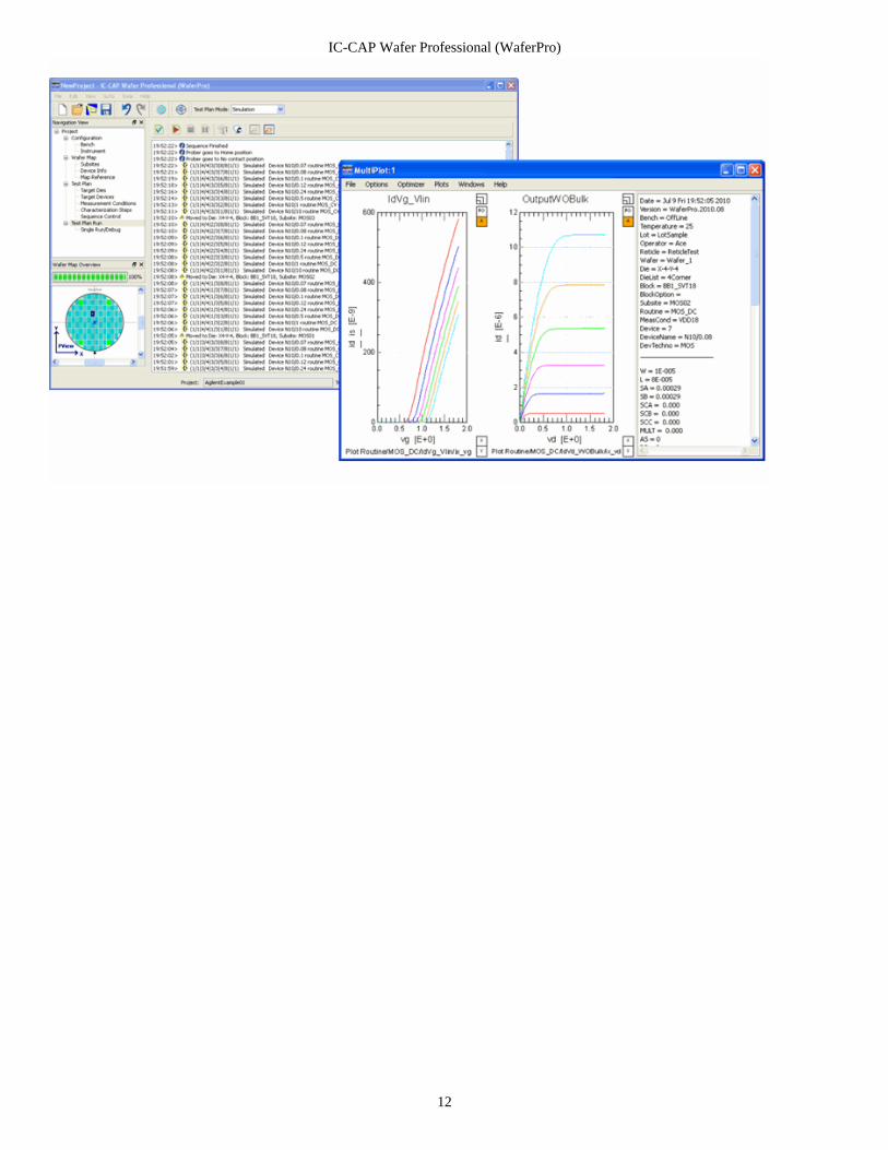
When you begin with the test plan execution, a second IC-CAP batch process runs in thebackground which runs the Test Plan. At any time during the execution, you can monitor acomprehensive log which shows the current test plan status and each single test results,including any failed or warning conditions and related comments. It is also possible toview the results of a particular test by simply selecting the specific test and opening therelated multiplot display.
Test Plan Run Page and Log Information with Display Capabilities
IC-CAP Wafer Professional (WaferPro)
12

IC-CAP Wafer Professional (WaferPro)
13
WaferPro Project EnvironmentThis section provides information on the following topics:
Using the WaferPro Project Interface (waferpro)Understanding the Project View (waferpro)Configuring a WaferPro Project (waferpro)Defining Wafer Layout Specification (Wafer Map) (waferpro)Block and Subsites Definition (waferpro)Device Info (waferpro)Test Plan Definition (waferpro)Target Dies (waferpro)Target Devices (waferpro)Measurement Conditions (waferpro)Characterization Steps (waferpro)Sequence Control (waferpro)Test Plan Run (waferpro)Single Run and Debug (waferpro)
IC-CAP Wafer Professional (WaferPro)
14
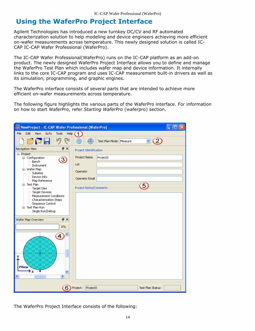
Using the WaferPro Project InterfaceAgilent Technologies has introduced a new turnkey DC/CV and RF automatedcharacterization solution to help modeling and device engineers achieving more efficienton-wafer measurements across temperature. This newly designed solution is called IC-CAP IC-CAP Wafer Professional (WaferPro).
The IC-CAP Wafer Professional(WaferPro) runs on the IC-CAP platform as an add-onproduct. The newly designed WaferPro Project Interface allows you to define and managethe WaferPro Test Plan which includes wafer map and device information. It internallylinks to the core IC-CAP program and uses IC-CAP measurement built-in drivers as well asits simulation, programming, and graphic engines.
The WaferPro interface consists of several parts that are intended to achieve moreefficient on-wafer measurements across temperature.
The following figure highlights the various parts of the WaferPro interface. For informationon how to start WaferPro, refer Starting WaferPro (waferpro) section.
The WaferPro Project Interface consists of the following:
IC-CAP Wafer Professional (WaferPro)
15
WaferPro Menu Bar (waferpro) - Contains all of the commands used in WaferPro.
WaferPro Tool Bar (waferpro) – Contains buttons that are shortcuts for commonly usedcommands.
Navigation View (waferpro) - Displays a hierarchical list of items in a WaferPro project.
Wafer Map Overview (waferpro) - Mini view of the main wafer map.
Workspace (waferpro) - A context-dependent area which is displayed according to theproject action selected from the Navigation View.
Status Bar (waferpro) - Displays the currently loaded project and the status of the testplan execution. Menu Bar
The top-level WaferPro menus are on the menu bar at the top of the WaferPro ProjectInterface.
File Menu
The File menu includes the following drop-down menus:
New Project - Creates a new WaferPro project.
Open Project - Opens an existing WaferPro project.
Open Example Project - Quickly opens an existing example WaferPro project.
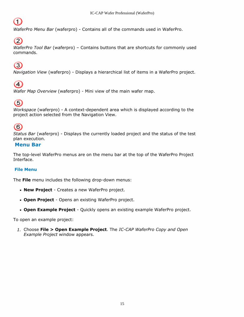
To open an example project:
Choose File > Open Example Project. The IC-CAP WaferPro Copy and Open1.Example Project window appears.
IC-CAP Wafer Professional (WaferPro)
16
Select a project and click OK. For information on the option in IC-CAP WaferPro Copy2.and Open Example Project window, refer An Example WaferPro Session (waferpro)section.
Save Project - Saves a new project to a specified measurement directory.
Close Window - Closes the WaferPro Project Interface.
Exit WaferPro - Prompts to save an existing open project and exit from WaferProapplication.
Edit Menu
The Edit menu includes the following drop-down menus:
Undo - The Undo button will "undo" any last action.
Not all actions can be “undone”. A warning dialog is displayed if the selected action cannot be undone. Thecommand Tools > Synchronize IC-CAP Routines is one such example as well as any file load or fileread commands.
Redo - The Redo button repeats any last action that was mistakenly erased.
View Menu
The view menu includes the following drop-down menus:
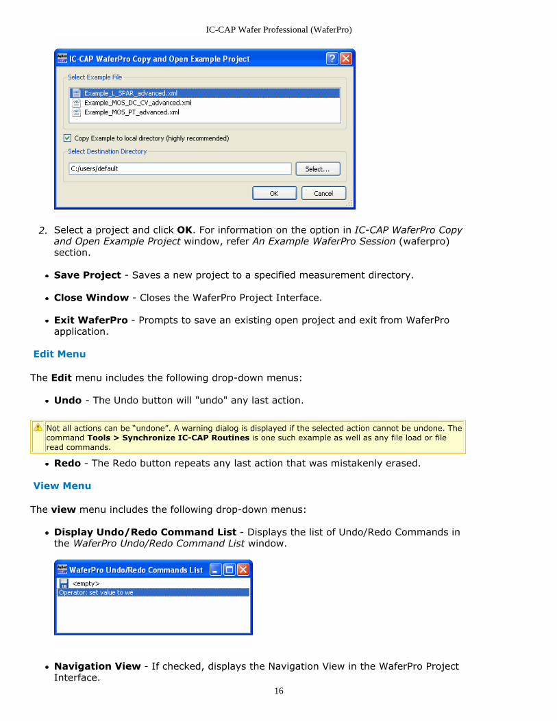
Display Undo/Redo Command List - Displays the list of Undo/Redo Commands inthe WaferPro Undo/Redo Command List window.
Navigation View - If checked, displays the Navigation View in the WaferPro ProjectInterface.
IC-CAP Wafer Professional (WaferPro)
17
Wafer Map Overview - If checked, displays the Wafer Map Overview in theWaferPro Project Interface.
GoTo Menu
The GoTo menu includes the following drop-down menus to access the various WaferProWorkspace options:
Project Configuration and Settings - Displays the general and optional settingsfor a project and a test plan, respectively.
Bench Settings - Displays options to set the Wafer Table and bench information.
Instrument Settings - Displays options to set the temperature and instrumentcontrol settings.
Wafer Map - Displays the Test Prober View with Wafer Map description and Diesettings.
Subsites - Displays the Subsites information.
Device Info - Displays the Probe Card and Device Type views.
Map Reference Settings - Displays the map reference information.
Test Plan - Displays the test result for the executed test plan.
Target Dies - You can edit the target dies information through Edit Target Diespane.
Target Devices - You can edit the target devices and view the list of target devices.
Measurement Conditions - Displays the measurement conditions; you can edit themeasurement conditions using Edit Measurement Conditions pane.
Characterization Steps - Displays the steps for characterization.
Sequence Control - Displays the sequence control of the test plan.
Test Plan Run and Monitor - Displays the Test Plan Run and Monitor window usingwhich you can view, run, and pause the test plan.
Single Run/Debug - Displays the mode and settings to run the test plan.
Tools Menu
The Tools menu includes the following drop-down menus to perform the device type andWaferPro settings:
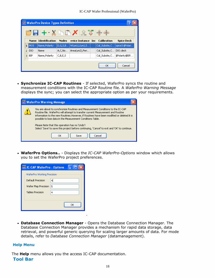
Edit Devices Types.. - Displays the WaferPro Device Type Definition window whichallows you to manage the device type definitions.
IC-CAP Wafer Professional (WaferPro)
18
Synchronize IC-CAP Routines - If selected, WaferPro syncs the routine andmeasurement conditions with the IC-CAP Routine file. A WaferPro Warning Messagedisplays the sync; you can select the appropriate option as per your requirements.
WaferPro Options.. - Displays the IC-CAP WaferPro-Options window which allowsyou to set the WaferPro project preferences.
.
Database Connection Manager - Opens the Database Connection Manager. TheDatabase Connection Manager provides a mechanism for rapid data storage, dataretrieval, and powerful generic querying for scaling larger amounts of data. For modedetails, refer to Database Connection Manager (datamanagement).
Help Menu
The Help menu allows you the access IC-CAP documentation. Tool Bar
IC-CAP Wafer Professional (WaferPro)
19
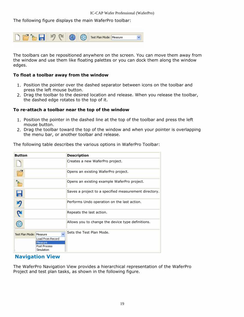
The following figure displays the main WaferPro toolbar:
The toolbars can be repositioned anywhere on the screen. You can move them away fromthe window and use them like floating palettes or you can dock them along the windowedges.
To float a toolbar away from the window
Position the pointer over the dashed separator between icons on the toolbar and1.press the left mouse button.Drag the toolbar to the desired location and release. When you release the toolbar,2.the dashed edge rotates to the top of it.
To re-attach a toolbar near the top of the window
Position the pointer in the dashed line at the top of the toolbar and press the left1.mouse button.Drag the toolbar toward the top of the window and when your pointer is overlapping2.the menu bar, or another toolbar and release.
The following table describes the various options in WaferPro Toolbar:
Button Description
Creates a new WaferPro project.
Opens an existing WaferPro project.
Opens an existing example WaferPro project.
Saves a project to a specified measurement directory.
Performs Undo operation on the last action.
Repeats the last action.
Allows you to change the device type definitions.
Sets the Test Plan Mode.
Navigation View
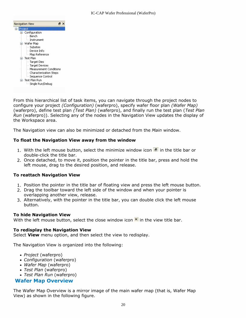
The WaferPro Navigation View provides a hierarchical representation of the WaferProProject and test plan tasks, as shown in the following figure.
IC-CAP Wafer Professional (WaferPro)
20
From this hierarchical list of task items, you can navigate through the project nodes toconfigure your project (Configuration) (waferpro), specify wafer floor plan (Wafer Map)(waferpro), define test plan (Test Plan) (waferpro), and finally run the test plan (Test PlanRun (waferpro)). Selecting any of the nodes in the Navigation View updates the display ofthe Workspace area.
The Navigation view can also be minimized or detached from the Main window.
To float the Navigation View away from the window
With the left mouse button, select the minimize window icon in the title bar or1.double-click the title bar.Once detached, to move it, position the pointer in the title bar, press and hold the2.left mouse, drag to the desired position, and release.
To reattach Navigation View
Position the pointer in the title bar of floating view and press the left mouse button.1.Drag the toolbar toward the left side of the window and when your pointer is2.overlapping another view, release.Alternatively, with the pointer in the title bar, you can double click the left mouse3.button.
To hide Navigation ViewWith the left mouse button, select the close window icon in the view title bar.
To redisplay the Navigation ViewSelect View menu option, and then select the view to redisplay.
The Navigation View is organized into the following:
Project (waferpro)Configuration (waferpro)Wafer Map (waferpro)Test Plan (waferpro)Test Plan Run (waferpro)
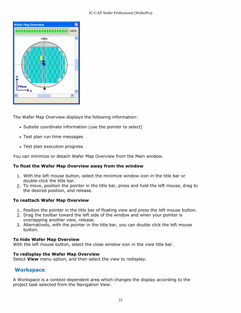
Wafer Map Overview
The Wafer Map Overview is a mirror image of the main wafer map (that is, Wafer MapView) as shown in the following figure.
IC-CAP Wafer Professional (WaferPro)
21
The Wafer Map Overview displays the following information:
Subsite coordinate information (use the pointer to select)
Test plan run time messages
Test plan execution progress
You can minimize or detach Wafer Map Overview from the Main window.
To float the Wafer Map Overview away from the window
With the left mouse button, select the minimize window icon in the title bar or1.double-click the title bar.To move, position the pointer in the title bar, press and hold the left mouse, drag to2.the desired position, and release.
To reattach Wafer Map Overview
Position the pointer in the title bar of floating view and press the left mouse button.1.Drag the toolbar toward the left side of the window and when your pointer is2.overlapping another view, release.Alternatively, with the pointer in the title bar, you can double click the left mouse3.button.
To hide Wafer Map OverviewWith the left mouse button, select the close window icon in the view title bar.
To redisplay the Wafer Map OverviewSelect View menu option, and then select the view to redisplay.
Workspace
A Workspace is a context-dependent area which changes the display according to theproject task selected from the Navigation View.
IC-CAP Wafer Professional (WaferPro)
22
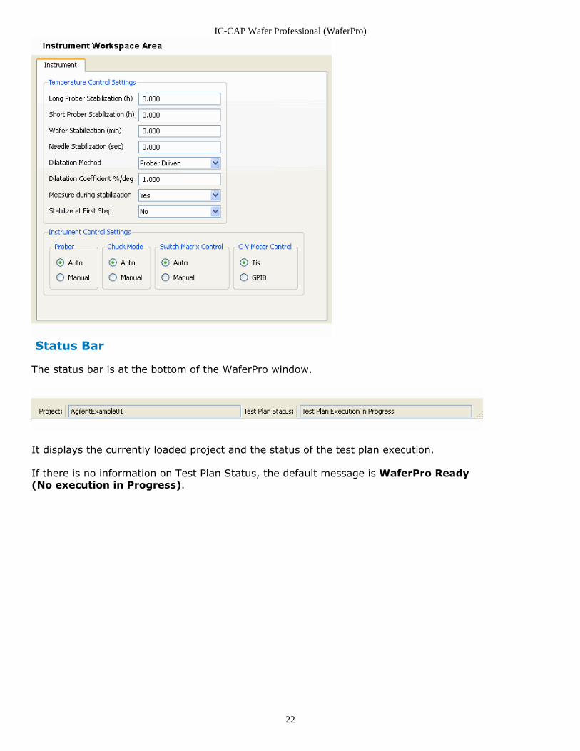
Status Bar
The status bar is at the bottom of the WaferPro window.
It displays the currently loaded project and the status of the test plan execution.
If there is no information on Test Plan Status, the default message is WaferPro Ready(No execution in Progress).
IC-CAP Wafer Professional (WaferPro)
23
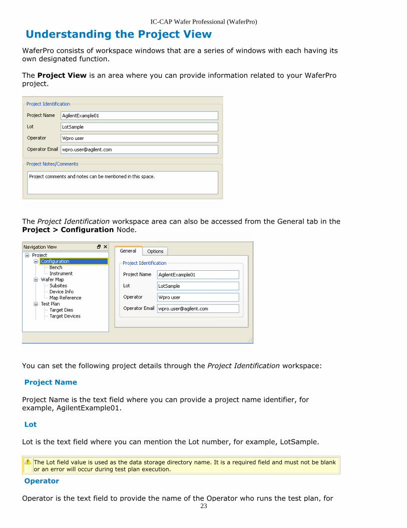
Understanding the Project ViewWaferPro consists of workspace windows that are a series of windows with each having itsown designated function.
The Project View is an area where you can provide information related to your WaferProproject.
The Project Identification workspace area can also be accessed from the General tab in theProject > Configuration Node.
You can set the following project details through the Project Identification workspace:
Project Name
Project Name is the text field where you can provide a project name identifier, forexample, AgilentExample01.
Lot
Lot is the text field where you can mention the Lot number, for example, LotSample.
The Lot field value is used as the data storage directory name. It is a required field and must not be blankor an error will occur during test plan execution.
Operator
Operator is the text field to provide the name of the Operator who runs the test plan, for

IC-CAP Wafer Professional (WaferPro)
24
example, Wpro user.
Operator Email
Operator Email is the text field to enter an Operator's email address, for example,[email protected].
Project Notes/Comments
You can enter any additional information about the current project.
IC-CAP Wafer Professional (WaferPro)
25
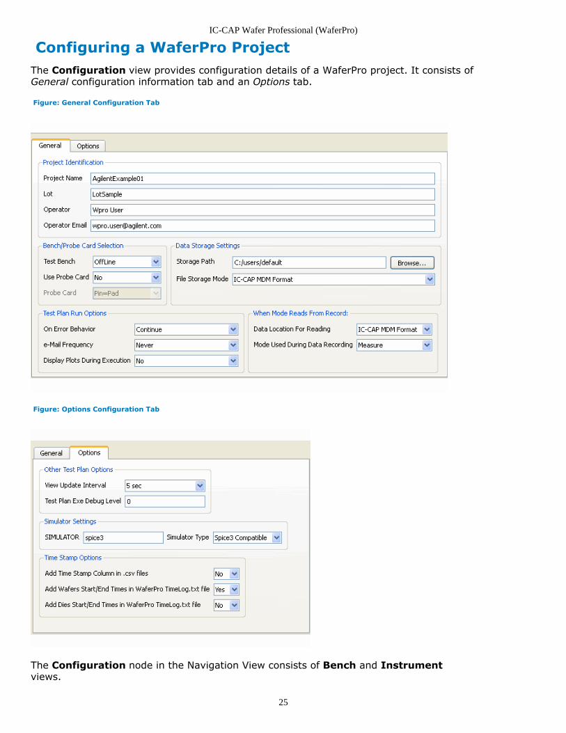
Configuring a WaferPro ProjectThe Configuration view provides configuration details of a WaferPro project. It consists ofGeneral configuration information tab and an Options tab.
Figure: General Configuration Tab
Figure: Options Configuration Tab
The Configuration node in the Navigation View consists of Bench and Instrumentviews.
IC-CAP Wafer Professional (WaferPro)
26
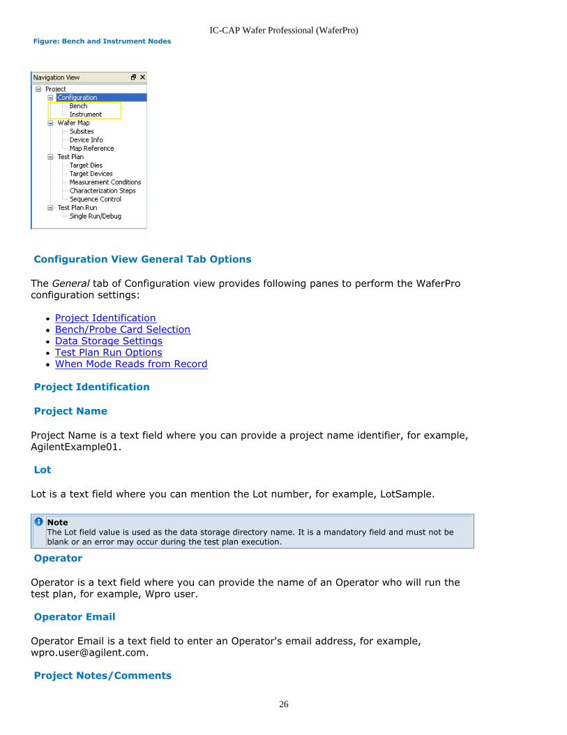
Figure: Bench and Instrument Nodes
Configuration View General Tab Options
The General tab of Configuration view provides following panes to perform the WaferProconfiguration settings:
Project IdentificationBench/Probe Card SelectionData Storage SettingsTest Plan Run OptionsWhen Mode Reads from Record
Project Identification
Project Name
Project Name is a text field where you can provide a project name identifier, for example,AgilentExample01.
Lot
Lot is a text field where you can mention the Lot number, for example, LotSample.
NoteThe Lot field value is used as the data storage directory name. It is a mandatory field and must not beblank or an error may occur during the test plan execution.
Operator
Operator is a text field where you can provide the name of an Operator who will run thetest plan, for example, Wpro user.
Operator Email
Operator Email is a text field to enter an Operator's email address, for example,[email protected].
Project Notes/Comments
IC-CAP Wafer Professional (WaferPro)
27
You can enter any additional information about the current project.
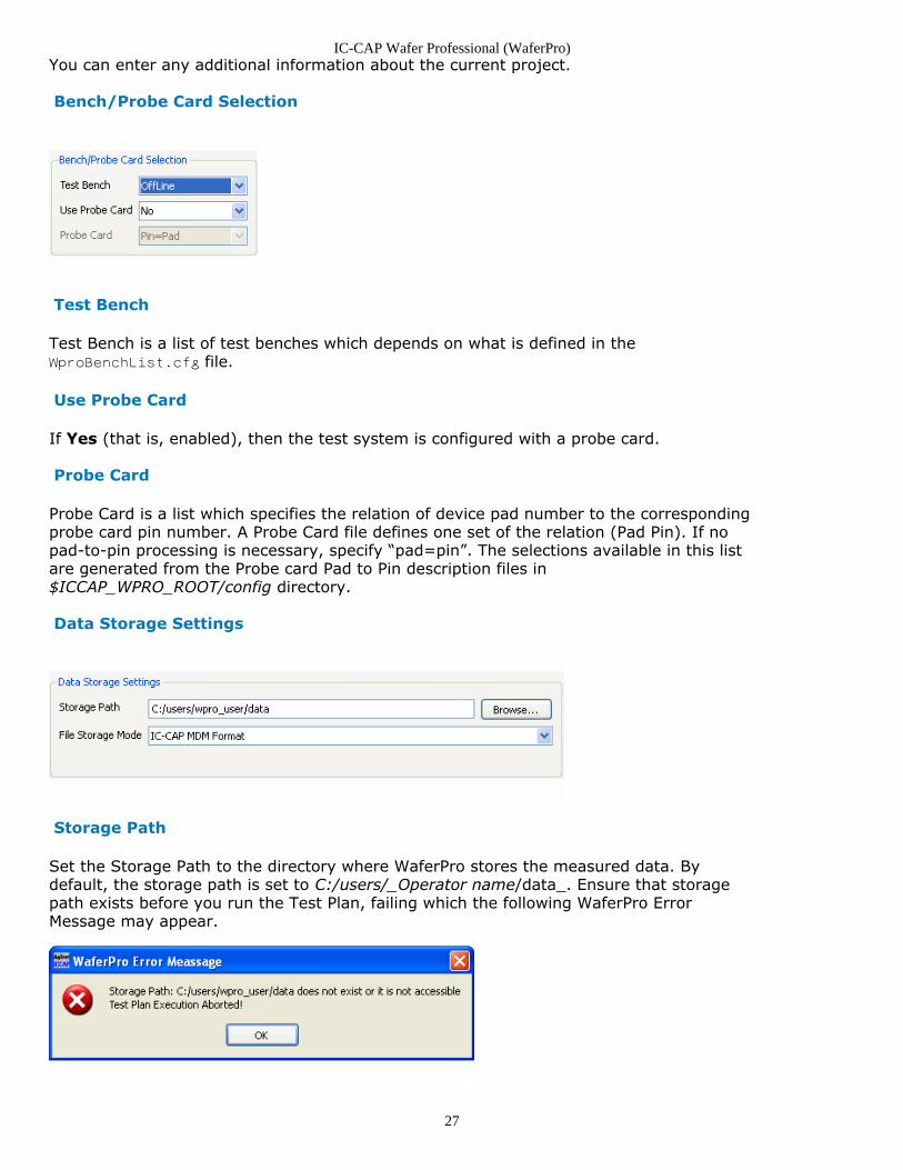
Bench/Probe Card Selection
Test Bench
Test Bench is a list of test benches which depends on what is defined in theWproBenchList.cfg file.
Use Probe Card
If Yes (that is, enabled), then the test system is configured with a probe card.
Probe Card
Probe Card is a list which specifies the relation of device pad number to the correspondingprobe card pin number. A Probe Card file defines one set of the relation (Pad Pin). If nopad-to-pin processing is necessary, specify “pad=pin”. The selections available in this listare generated from the Probe card Pad to Pin description files in$ICCAP_WPRO_ROOT/config directory.
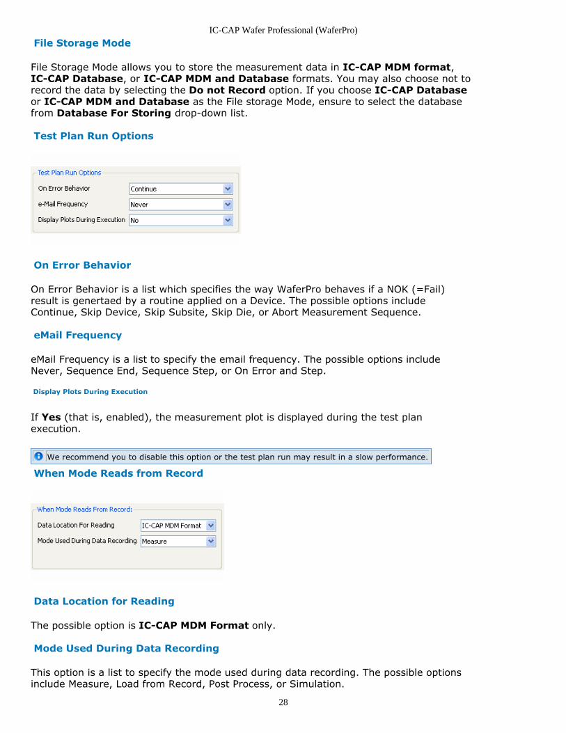
Data Storage Settings
Storage Path
Set the Storage Path to the directory where WaferPro stores the measured data. Bydefault, the storage path is set to C:/users/_Operator name/data_. Ensure that storagepath exists before you run the Test Plan, failing which the following WaferPro ErrorMessage may appear.
IC-CAP Wafer Professional (WaferPro)
28
File Storage Mode
File Storage Mode allows you to store the measurement data in IC-CAP MDM format,IC-CAP Database, or IC-CAP MDM and Database formats. You may also choose not torecord the data by selecting the Do not Record option. If you choose IC-CAP Databaseor IC-CAP MDM and Database as the File storage Mode, ensure to select the databasefrom Database For Storing drop-down list.
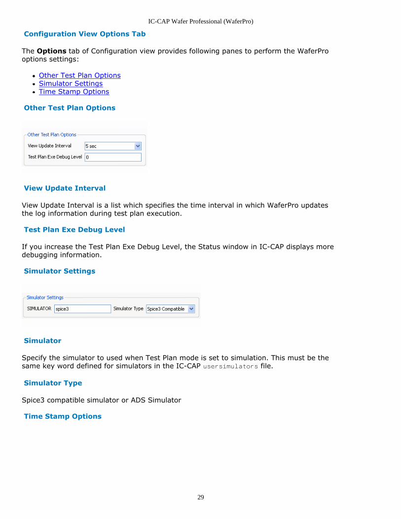
Test Plan Run Options
On Error Behavior
On Error Behavior is a list which specifies the way WaferPro behaves if a NOK (=Fail)result is genertaed by a routine applied on a Device. The possible options includeContinue, Skip Device, Skip Subsite, Skip Die, or Abort Measurement Sequence.
eMail Frequency
eMail Frequency is a list to specify the email frequency. The possible options includeNever, Sequence End, Sequence Step, or On Error and Step.
Display Plots During Execution
If Yes (that is, enabled), the measurement plot is displayed during the test planexecution.
We recommend you to disable this option or the test plan run may result in a slow performance.
When Mode Reads from Record
Data Location for Reading
The possible option is IC-CAP MDM Format only.
Mode Used During Data Recording
This option is a list to specify the mode used during data recording. The possible optionsinclude Measure, Load from Record, Post Process, or Simulation.
IC-CAP Wafer Professional (WaferPro)
29
Configuration View Options Tab
The Options tab of Configuration view provides following panes to perform the WaferProoptions settings:
Other Test Plan OptionsSimulator SettingsTime Stamp Options
Other Test Plan Options
View Update Interval
View Update Interval is a list which specifies the time interval in which WaferPro updatesthe log information during test plan execution.
Test Plan Exe Debug Level
If you increase the Test Plan Exe Debug Level, the Status window in IC-CAP displays moredebugging information.
Simulator Settings
Simulator
Specify the simulator to used when Test Plan mode is set to simulation. This must be thesame key word defined for simulators in the IC-CAP usersimulators file.
Simulator Type
Spice3 compatible simulator or ADS Simulator
Time Stamp Options
IC-CAP Wafer Professional (WaferPro)
30
Add Time Stamp Column in .csv files
If enabled (Yes), this option adds a time stamp to the measured data in .csv files.
Add Wafers Start/End Times in WaferPro TimeLog.txt file
If enabled (Yes), this option logs the start and end time of the wafer in the TimeLog.txtfile. The TimeLog.txt file is available in the specified Storage Directory and the Lot Name.
Add Dies Start/End Times in WaferPro TimeLog.txt file
If enabled (Yes), this option logs the start and end time of the dies in the TimeLog.txt file.The TimeLog.txt file is available in the specified Storage Directory and the Lot Name.
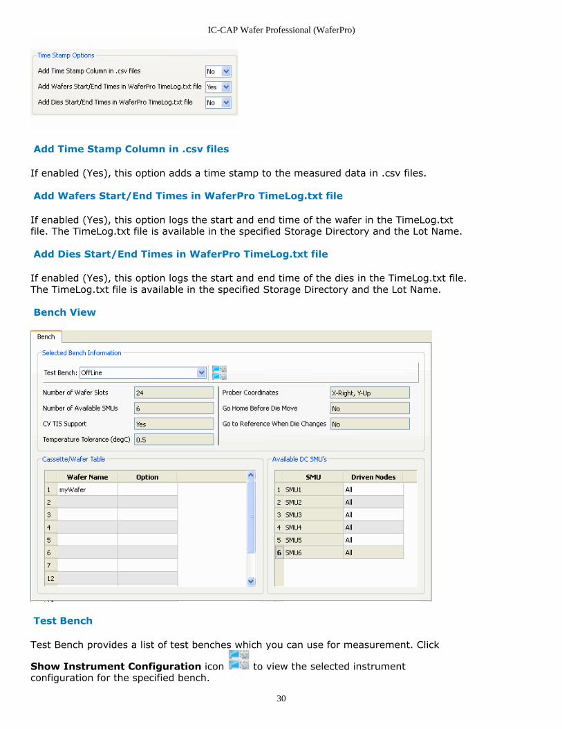
Bench View
Test Bench
Test Bench provides a list of test benches which you can use for measurement. Click
Show Instrument Configuration icon to view the selected instrumentconfiguration for the specified bench.

IC-CAP Wafer Professional (WaferPro)
31
The Test Bench information is read from the ICCAP_WPRO_ROOT/config/ wproBenchList.cfg file. Thisconfiguration file provides a list of available Test Benches, number of wafer slots, and the number ofAvailable SMUs for a specific bench.
Number of Wafer Slots
Number of Wafer Slots is a non-editable field which displays the number of Wafer slots forthe currently selected bench.
Number of Available SMUs
Number of Available SMUs is a non-editable field which displays the number of availableSMUs for the parametric test instrument used in the currently selected bench.
CV TIS Support
CV TIS Support is a non-editable field which displays if the currently selected benchsupports CV measurements controlled via the TIS.
CV TIS Support is only valid for test benches configured with an Agilent 407x/408x parametric testsystem.
Prober Coordinates
These Coordinate Systems are Prober Manufacturer dependent and specified in the benchconfiguration. For example, Cascade Probers are X-Right Y-Up.WaferPro combines Prober Coordinates, Doc Coordinates, and the Wafer Loading Anglewhich determines the coordinates to be send to the prober for a move command.
Cassette/Wafer Table
If you are using an automated prober, the test plan can be applied to several wafers. Thecassette/wafer table specifies the slot where each test wafer is located. The length of thistable is based on the setting for the Number of available Wafer Slots.
Available DC SMU’s
Lists the available SMUs and specifies the SMU which you can use to measure a specifiednode. The possible settings include:
You can leave this field blank to indicate that an SMU must not be used formeasurements.Set to “All” if the SMU is functional and can be used to measure any device node.Set to specific nodes where the SMU must be used. A typical case to use this settingis for SMUs which have weak measurement accuracy or can only force bias.
Temperature Tolerance (degC)
If the difference between current temperature and temperature set is higher than thistolerance value, WaferPro activates the action of changing temperature.
Go Home Before Die Move
If set to Yes, the probe head moves back to the Home position on the wafer beforemoving from die to die.
Go to Reference When Die Changes
IC-CAP Wafer Professional (WaferPro)
32
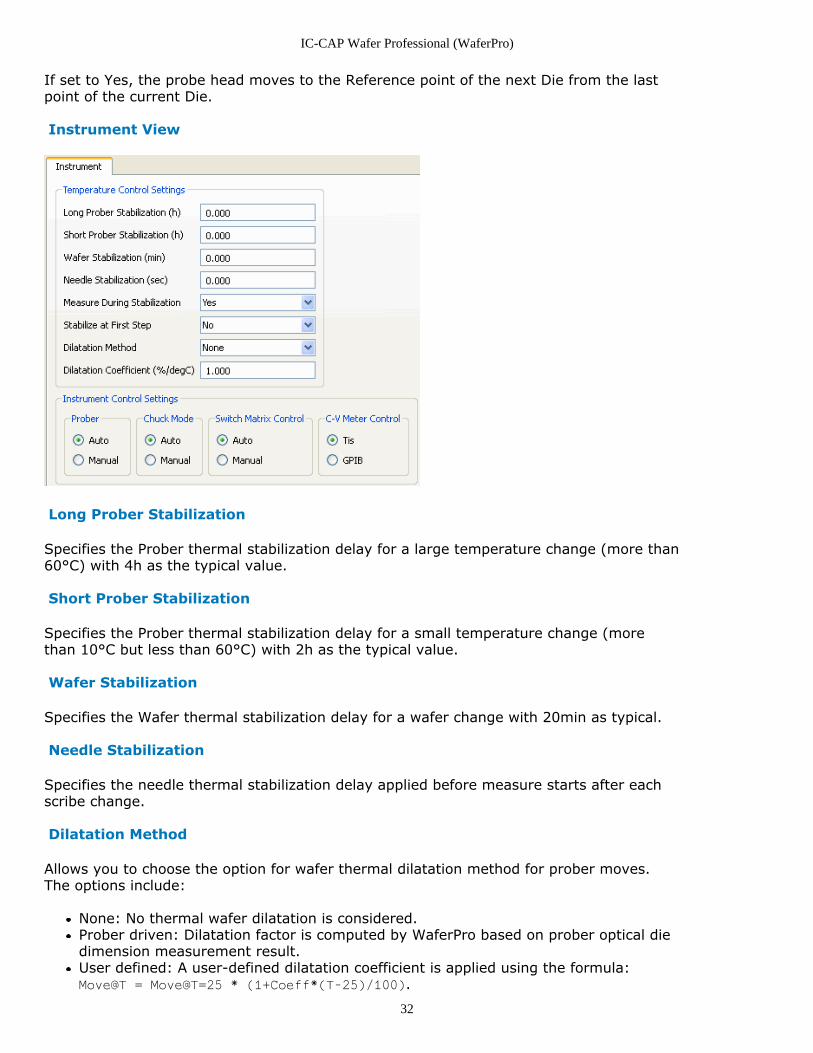
If set to Yes, the probe head moves to the Reference point of the next Die from the lastpoint of the current Die.
Instrument View
Long Prober Stabilization
Specifies the Prober thermal stabilization delay for a large temperature change (more than60°C) with 4h as the typical value.
Short Prober Stabilization
Specifies the Prober thermal stabilization delay for a small temperature change (morethan 10°C but less than 60°C) with 2h as the typical value.
Wafer Stabilization
Specifies the Wafer thermal stabilization delay for a wafer change with 20min as typical.
Needle Stabilization
Specifies the needle thermal stabilization delay applied before measure starts after eachscribe change.
Dilatation Method
Allows you to choose the option for wafer thermal dilatation method for prober moves.The options include:
None: No thermal wafer dilatation is considered.Prober driven: Dilatation factor is computed by WaferPro based on prober optical diedimension measurement result.User defined: A user-defined dilatation coefficient is applied using the formula:Move@T = Move@T=25 * (1+Coeff*(T-25)/100).
IC-CAP Wafer Professional (WaferPro)
33
Dilatation Coefficient
If Dilatation Method is selected, the dilatation coefficient in %/deg is used in the dilatationformula.
Instrument Control Settings
Instrument Control Settings allows you to set either Auto or Manual control Mode for theProber, Switching Matrix, and Chuck. It also allows the operator to set the CV-Metercontrol to either the TIS or GPIB. The TIS setting is only for the Agilent 407x/8x family ofParametric Test Systems.
Measure During stabilization
If enabled (set to Yes), during prober stabilization delay, WaferPro performs themeasurement and runs automated alignment every 5 minutes. If disabled (set to No),WaferPro waits until stabilization delay time expires before starting the measurement.
Stabilize at First Step
This option is used to optimize stabilization sequence.
Wafer Stabilization is performed after wafer loading and before temperature change.Wafer Stabilization is not done at the first sequence step. It is done only if Stabilizeat First Step is set to Yes.Prober Stabilization is performed after changing temperature. Temperature changefollowed by Prober Stabilization is performed when:
DeltaTemp is more than Temperature Tolerance set in Bench, orAt the first sequence step with Stabilize at First Step is set to Yes or YesExcept WaferStab.
Notes
WaferPro prober drivers use index move. As a consequence, wafer dilatation has a weak impact onprober moves.Measure while stabilizing and Prober driven dilatation method must be disabled if the prober doesnot support optic index move and automated alignments. (UF300 and UF3000 support optic basedindex move and automated alignments.)
IC-CAP Wafer Professional (WaferPro)
34
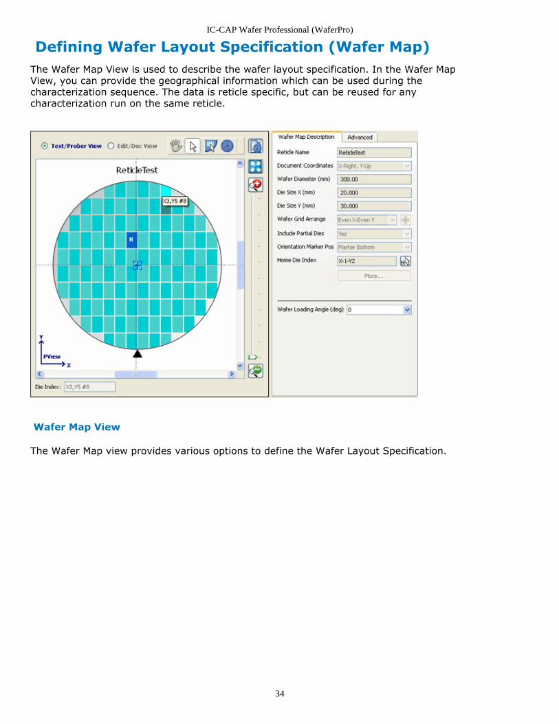
Defining Wafer Layout Specification (Wafer Map)The Wafer Map View is used to describe the wafer layout specification. In the Wafer MapView, you can provide the geographical information which can be used during thecharacterization sequence. The data is reticle specific, but can be reused for anycharacterization run on the same reticle.
Wafer Map View
The Wafer Map view provides various options to define the Wafer Layout Specification.
IC-CAP Wafer Professional (WaferPro)
35
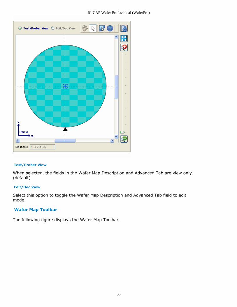
Test/Prober View
When selected, the fields in the Wafer Map Description and Advanced Tab are view only.(default)
Edit/Doc View
Select this option to toggle the Wafer Map Description and Advanced Tab field to editmode.
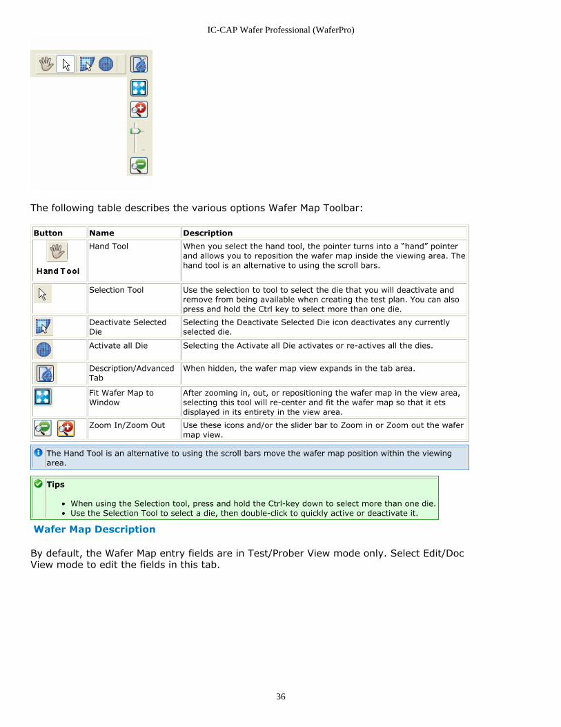
Wafer Map Toolbar
The following figure displays the Wafer Map Toolbar.
IC-CAP Wafer Professional (WaferPro)
36
The following table describes the various options Wafer Map Toolbar:
Button Name Description
Hand Tool When you select the hand tool, the pointer turns into a “hand” pointerand allows you to reposition the wafer map inside the viewing area. Thehand tool is an alternative to using the scroll bars.
Selection Tool Use the selection to tool to select the die that you will deactivate andremove from being available when creating the test plan. You can alsopress and hold the Ctrl key to select more than one die.
Deactivate SelectedDie
Selecting the Deactivate Selected Die icon deactivates any currentlyselected die.
Activate all Die Selecting the Activate all Die activates or re-actives all the dies.
Description/AdvancedTab
When hidden, the wafer map view expands in the tab area.
Fit Wafer Map toWindow
After zooming in, out, or repositioning the wafer map in the view area,selecting this tool will re-center and fit the wafer map so that it etsdisplayed in its entirety in the view area.
Zoom In/Zoom Out Use these icons and/or the slider bar to Zoom in or Zoom out the wafermap view.
The Hand Tool is an alternative to using the scroll bars move the wafer map position within the viewingarea.
Tips
When using the Selection tool, press and hold the Ctrl-key down to select more than one die.Use the Selection Tool to select a die, then double-click to quickly active or deactivate it.
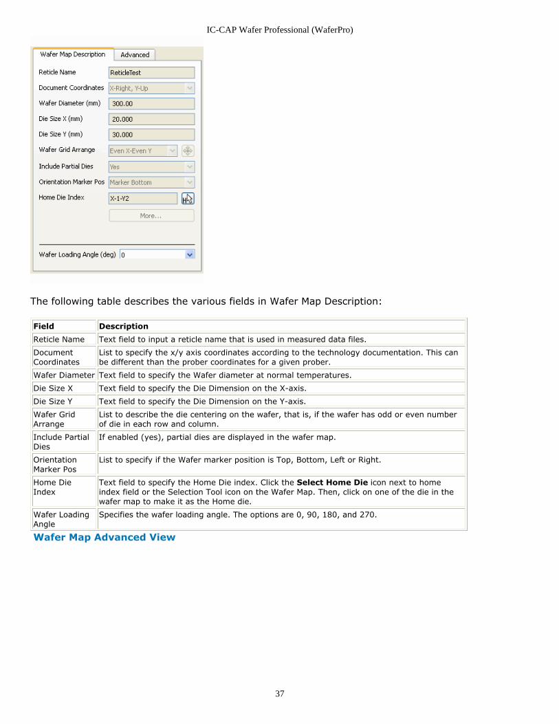
Wafer Map Description
By default, the Wafer Map entry fields are in Test/Prober View mode only. Select Edit/DocView mode to edit the fields in this tab.
IC-CAP Wafer Professional (WaferPro)
37
The following table describes the various fields in Wafer Map Description:
Field Description
Reticle Name Text field to input a reticle name that is used in measured data files.
DocumentCoordinates
List to specify the x/y axis coordinates according to the technology documentation. This canbe different than the prober coordinates for a given prober.
Wafer Diameter Text field to specify the Wafer diameter at normal temperatures.
Die Size X Text field to specify the Die Dimension on the X-axis.
Die Size Y Text field to specify the Die Dimension on the Y-axis.
Wafer GridArrange
List to describe the die centering on the wafer, that is, if the wafer has odd or even numberof die in each row and column.
Include PartialDies
If enabled (yes), partial dies are displayed in the wafer map.
OrientationMarker Pos
List to specify if the Wafer marker position is Top, Bottom, Left or Right.
Home DieIndex
Text field to specify the Home Die index. Click the Select Home Die icon next to homeindex field or the Selection Tool icon on the Wafer Map. Then, click on one of the die in thewafer map to make it as the Home die.
Wafer LoadingAngle
Specifies the wafer loading angle. The options are 0, 90, 180, and 270.
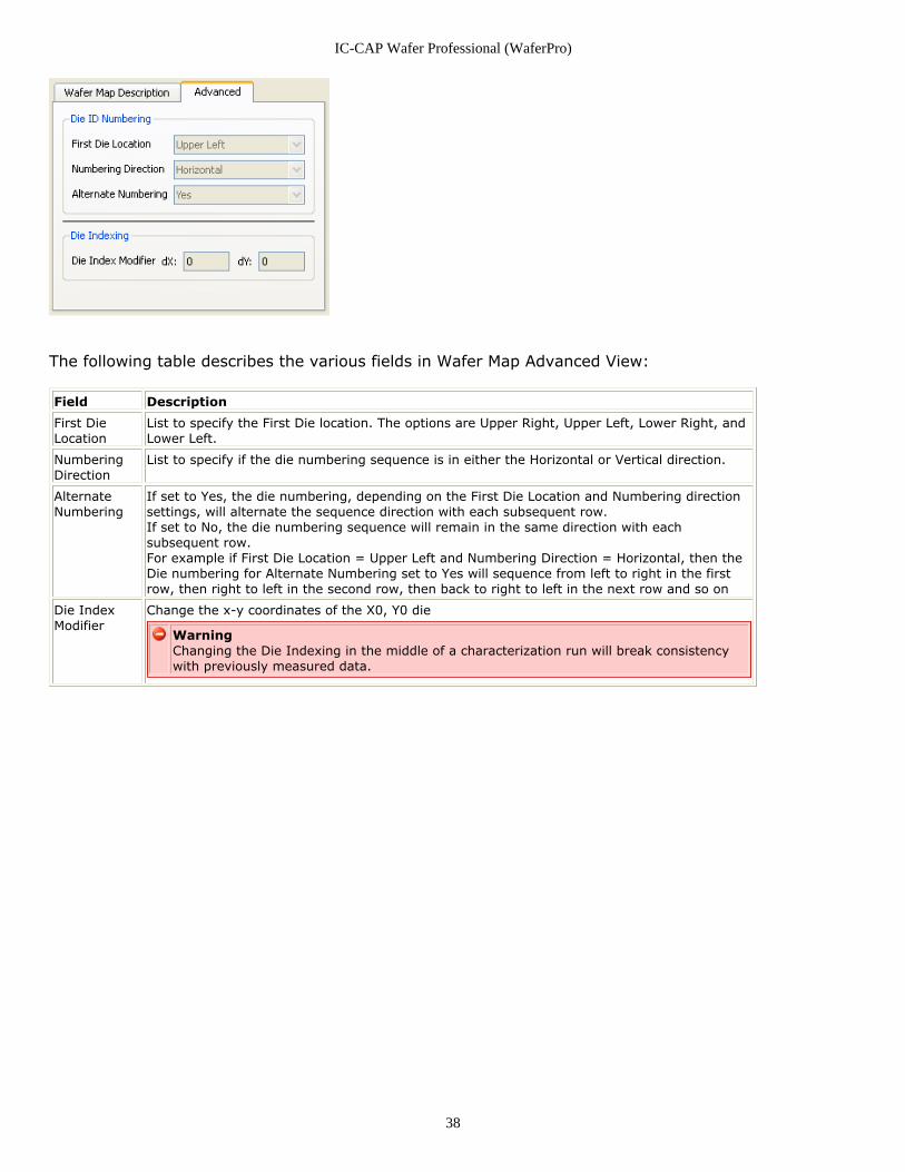
Wafer Map Advanced View
IC-CAP Wafer Professional (WaferPro)
38
The following table describes the various fields in Wafer Map Advanced View:
Field Description
First DieLocation
List to specify the First Die location. The options are Upper Right, Upper Left, Lower Right, andLower Left.
NumberingDirection
List to specify if the die numbering sequence is in either the Horizontal or Vertical direction.
AlternateNumbering
If set to Yes, the die numbering, depending on the First Die Location and Numbering directionsettings, will alternate the sequence direction with each subsequent row.If set to No, the die numbering sequence will remain in the same direction with eachsubsequent row.For example if First Die Location = Upper Left and Numbering Direction = Horizontal, then theDie numbering for Alternate Numbering set to Yes will sequence from left to right in the firstrow, then right to left in the second row, then back to right to left in the next row and so on
Die IndexModifier
Change the x-y coordinates of the X0, Y0 die
WarningChanging the Die Indexing in the middle of a characterization run will break consistencywith previously measured data.
IC-CAP Wafer Professional (WaferPro)
39
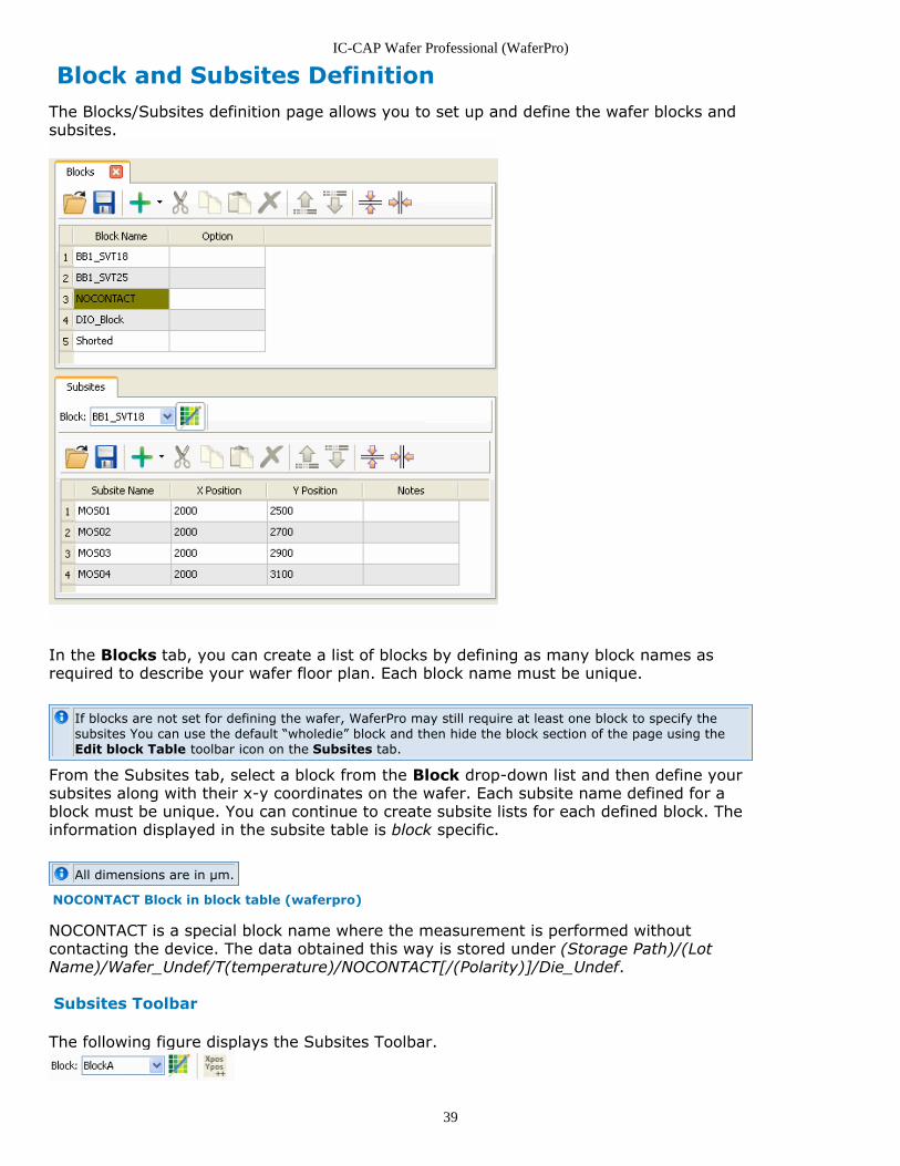
Block and Subsites DefinitionThe Blocks/Subsites definition page allows you to set up and define the wafer blocks andsubsites.
In the Blocks tab, you can create a list of blocks by defining as many block names asrequired to describe your wafer floor plan. Each block name must be unique.
If blocks are not set for defining the wafer, WaferPro may still require at least one block to specify thesubsites You can use the default “wholedie” block and then hide the block section of the page using theEdit block Table toolbar icon on the Subsites tab.
From the Subsites tab, select a block from the Block drop-down list and then define yoursubsites along with their x-y coordinates on the wafer. Each subsite name defined for ablock must be unique. You can continue to create subsite lists for each defined block. Theinformation displayed in the subsite table is block specific.
All dimensions are in µm.
NOCONTACT Block in block table (waferpro)
NOCONTACT is a special block name where the measurement is performed withoutcontacting the device. The data obtained this way is stored under (Storage Path)/(LotName)/Wafer_Undef/T(temperature)/NOCONTACT[/(Polarity)]/Die_Undef.
Subsites Toolbar
The following figure displays the Subsites Toolbar.
IC-CAP Wafer Professional (WaferPro)
40
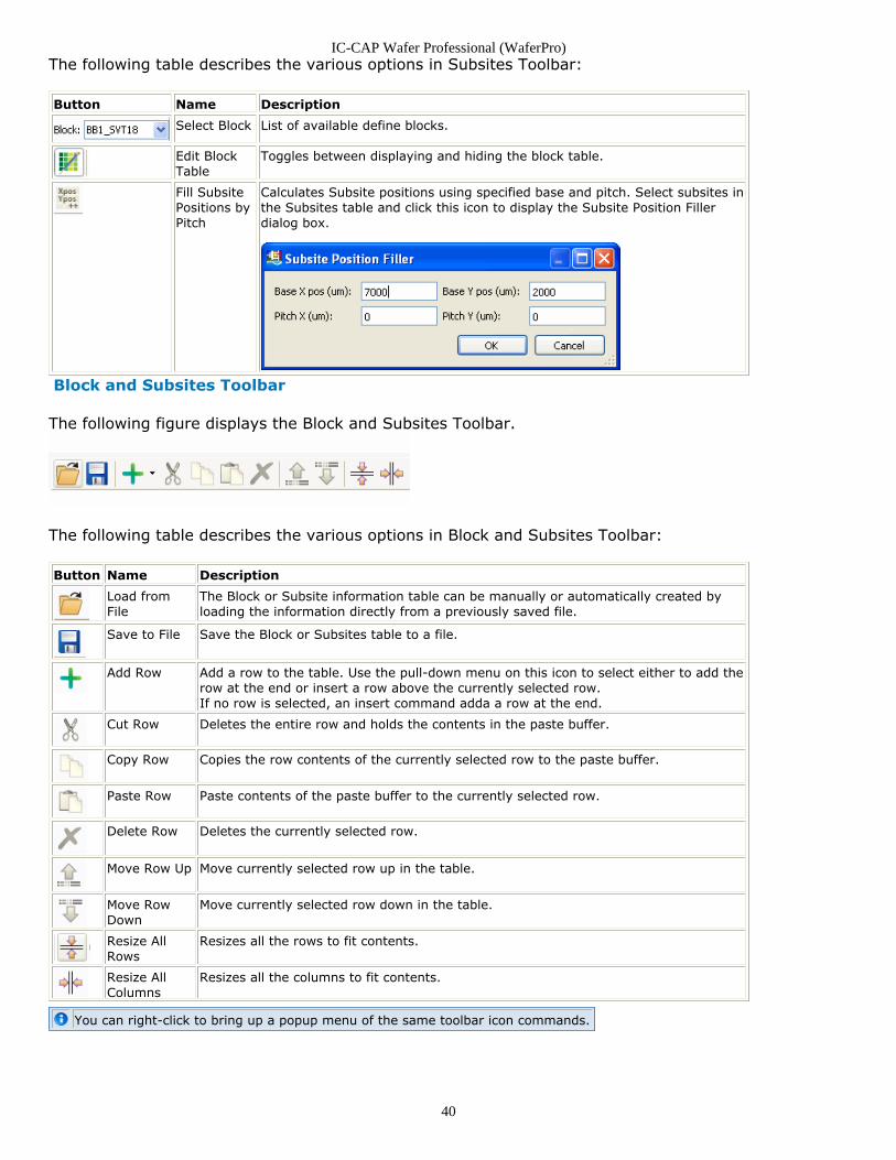
The following table describes the various options in Subsites Toolbar:
Button Name Description
Select Block List of available define blocks.
Edit BlockTable
Toggles between displaying and hiding the block table.
Fill SubsitePositions byPitch
Calculates Subsite positions using specified base and pitch. Select subsites inthe Subsites table and click this icon to display the Subsite Position Fillerdialog box.
Block and Subsites Toolbar
The following figure displays the Block and Subsites Toolbar.
The following table describes the various options in Block and Subsites Toolbar:
Button Name Description
Load fromFile
The Block or Subsite information table can be manually or automatically created byloading the information directly from a previously saved file.
Save to File Save the Block or Subsites table to a file.
Add Row Add a row to the table. Use the pull-down menu on this icon to select either to add therow at the end or insert a row above the currently selected row.If no row is selected, an insert command adda a row at the end.
Cut Row Deletes the entire row and holds the contents in the paste buffer.
Copy Row Copies the row contents of the currently selected row to the paste buffer.
Paste Row Paste contents of the paste buffer to the currently selected row.
Delete Row Deletes the currently selected row.
Move Row Up Move currently selected row up in the table.
Move RowDown
Move currently selected row down in the table.
Resize AllRows
Resizes all the rows to fit contents.
Resize AllColumns
Resizes all the columns to fit contents.
You can right-click to bring up a popup menu of the same toolbar icon commands.
IC-CAP Wafer Professional (WaferPro)
41
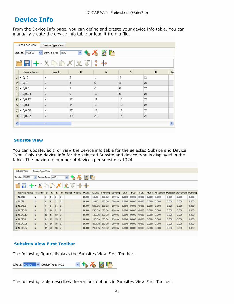
Device InfoFrom the Device Info page, you can define and create your device info table. You canmanually create the device info table or load it from a file.
Subsite View
You can update, edit, or view the device info table for the selected Subsite and DeviceType. Only the device info for the selected Subsite and device type is displayed in thetable. The maximum number of devices per subsite is 1024.
Subsites View First Toolbar
The following figure displays the Subsites View First Toolbar.
The following table describes the various options in Subsites View First Toolbar:
IC-CAP Wafer Professional (WaferPro)
42
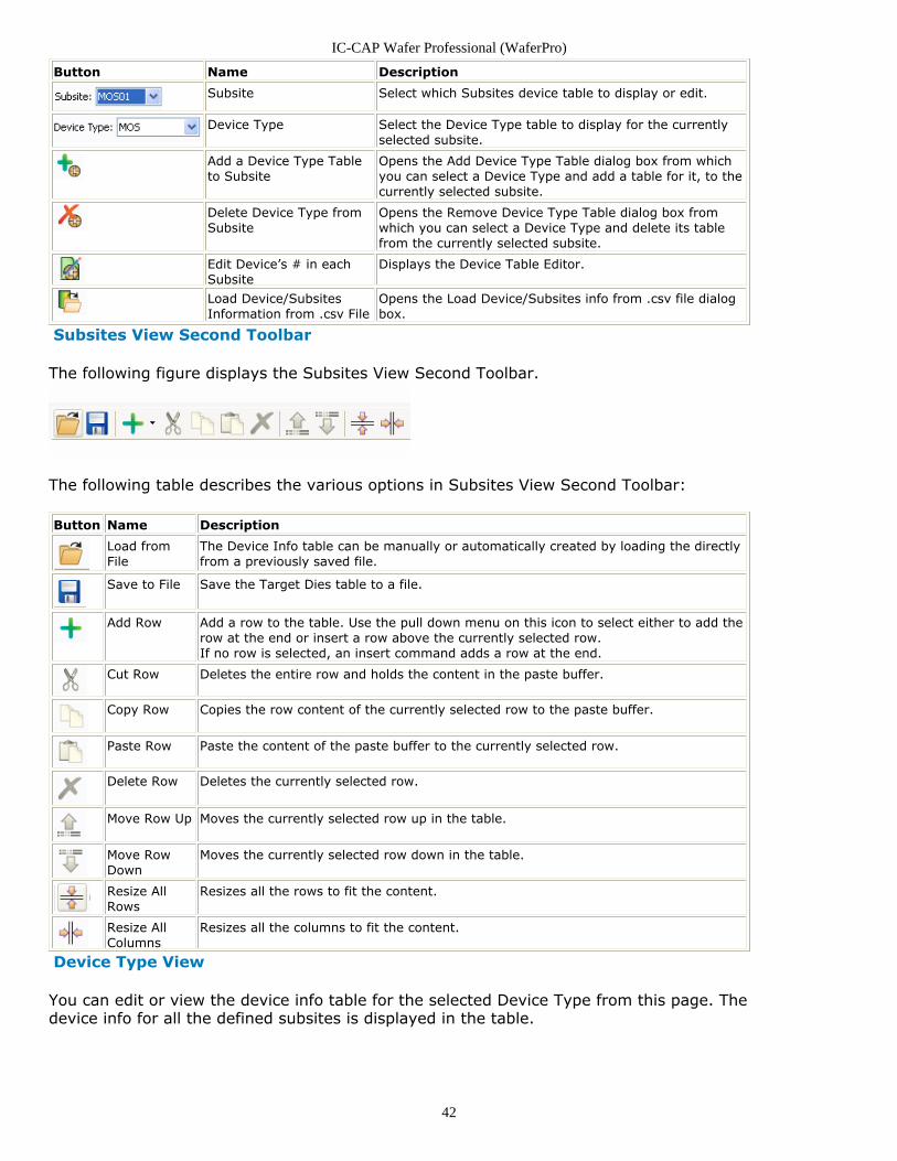
Button Name Description
Subsite Select which Subsites device table to display or edit.
Device Type Select the Device Type table to display for the currentlyselected subsite.
Add a Device Type Tableto Subsite
Opens the Add Device Type Table dialog box from whichyou can select a Device Type and add a table for it, to thecurrently selected subsite.
Delete Device Type fromSubsite
Opens the Remove Device Type Table dialog box fromwhich you can select a Device Type and delete its tablefrom the currently selected subsite.
Edit Device’s # in eachSubsite
Displays the Device Table Editor.
Load Device/SubsitesInformation from .csv File
Opens the Load Device/Subsites info from .csv file dialogbox.
Subsites View Second Toolbar
The following figure displays the Subsites View Second Toolbar.
The following table describes the various options in Subsites View Second Toolbar:
Button Name Description
Load fromFile
The Device Info table can be manually or automatically created by loading the directlyfrom a previously saved file.
Save to File Save the Target Dies table to a file.
Add Row Add a row to the table. Use the pull down menu on this icon to select either to add therow at the end or insert a row above the currently selected row.If no row is selected, an insert command adds a row at the end.
Cut Row Deletes the entire row and holds the content in the paste buffer.
Copy Row Copies the row content of the currently selected row to the paste buffer.
Paste Row Paste the content of the paste buffer to the currently selected row.
Delete Row Deletes the currently selected row.
Move Row Up Moves the currently selected row up in the table.
Move RowDown
Moves the currently selected row down in the table.
Resize AllRows
Resizes all the rows to fit the content.
Resize AllColumns
Resizes all the columns to fit the content.
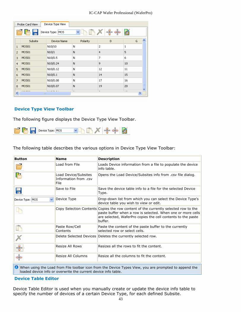
Device Type View
You can edit or view the device info table for the selected Device Type from this page. Thedevice info for all the defined subsites is displayed in the table.
IC-CAP Wafer Professional (WaferPro)
43
Device Type View Toolbar
The following figure displays the Device Type View Toolbar.
The following table describes the various options in Device Type View Toolbar:
Button Name Description
Load from File Loads Device information from a file to populate the deviceinfo table.
Load Device/SubsitesInformation from .csvFile
Opens the Load Device/Subsites info from .csv file dialog.
Save to File Save the device table info to a file for the selected DeviceType.
Device Type Drop-down list from which you can select the Device Type’sdevice table you wish to view or edit.
Copy Selection Contents Copies the row content of the currently selected row to thepaste buffer when a row is selected. When one or more cellsare selected, WaferPro copies the cell contents to the pastebuffer.
Paste Row/CellContents
Paste the content of the paste buffer to the currentlyselected row or select cells.
Delete Selected Devices Deletes the currently selected row.
Resize All Rows Resizes all the rows to fit the content.
Resize All Columns Resize all the columns to fit the content.
When using the Load from File toolbar icon from the Device Types View, you are prompted to append theloaded device info or overwrite the current device info table.
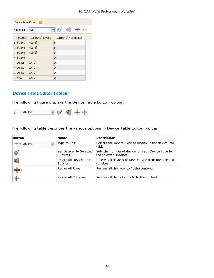
Device Table Editor
Device Table Editor is used when you manually create or update the device info table tospecify the number of devices of a certain Device Type, for each defined Subsite.
IC-CAP Wafer Professional (WaferPro)
44
Device Table Editor Toolbar
The following figure displays the Device Table Editor Toolbar.
The following table describes the various options in Device Table Editor Toolbar:
Button Name Description
Type to Edit Selects the Device Type to display in the device infotable.
Set Devices to SelectedSubsites
Sets the number of device for each Device Type forthe selected subsites.
Delete All Devices fromSubsite
Deletes all devices of Device Type from the selectedsubsites.
Resize All Rows Resizes all the rows to fit the content.
Resize All Columns Resizes all the columns to fit the content.
IC-CAP Wafer Professional (WaferPro)
45
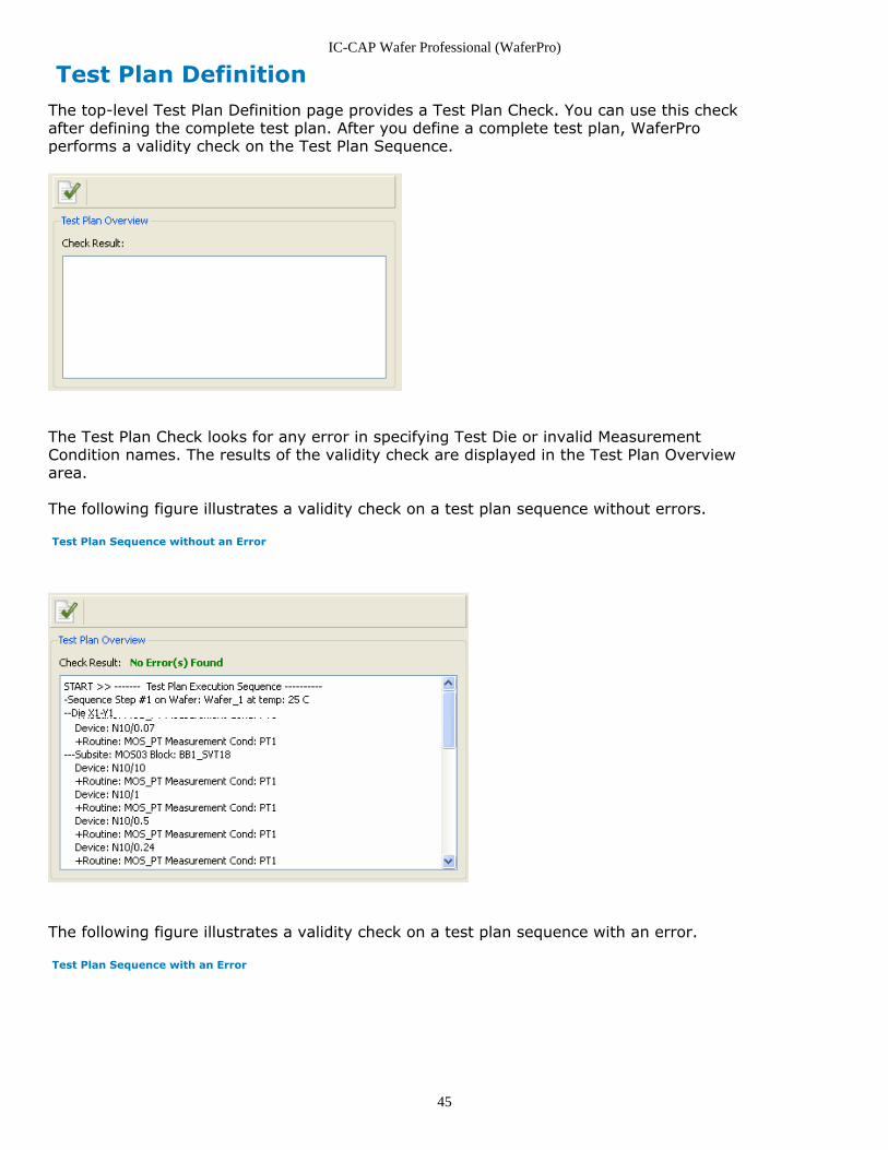
Test Plan DefinitionThe top-level Test Plan Definition page provides a Test Plan Check. You can use this checkafter defining the complete test plan. After you define a complete test plan, WaferProperforms a validity check on the Test Plan Sequence.
The Test Plan Check looks for any error in specifying Test Die or invalid MeasurementCondition names. The results of the validity check are displayed in the Test Plan Overviewarea.
The following figure illustrates a validity check on a test plan sequence without errors.
Test Plan Sequence without an Error
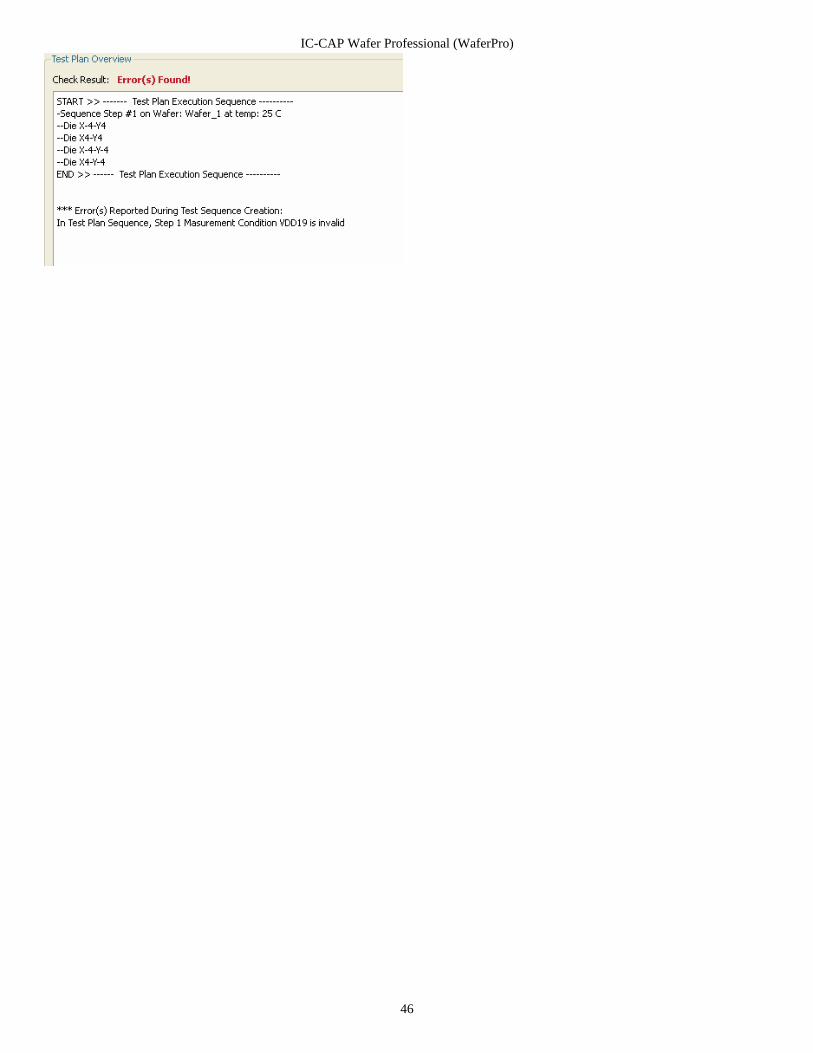
The following figure illustrates a validity check on a test plan sequence with an error.
Test Plan Sequence with an Error
IC-CAP Wafer Professional (WaferPro)
46
IC-CAP Wafer Professional (WaferPro)
47
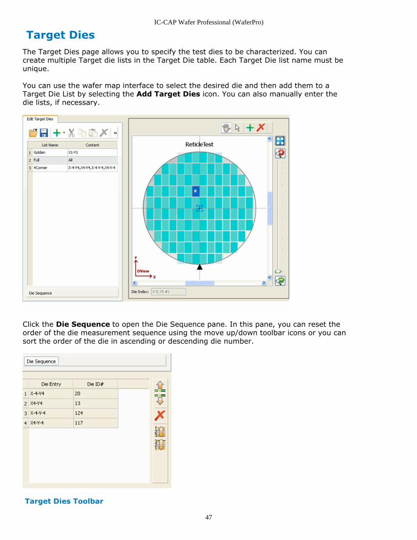
Target DiesThe Target Dies page allows you to specify the test dies to be characterized. You cancreate multiple Target die lists in the Target Die table. Each Target Die list name must beunique.
You can use the wafer map interface to select the desired die and then add them to aTarget Die List by selecting the Add Target Dies icon. You can also manually enter thedie lists, if necessary.
Click the Die Sequence to open the Die Sequence pane. In this pane, you can reset theorder of the die measurement sequence using the move up/down toolbar icons or you cansort the order of the die in ascending or descending die number.
Target Dies Toolbar
IC-CAP Wafer Professional (WaferPro)
48
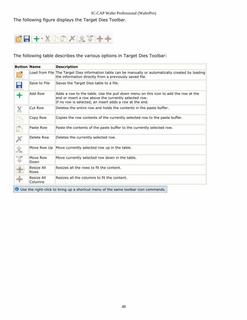
The following figure displays the Target Dies Toolbar.
The following table describes the various options in Target Dies Toolbar:
Button Name Description
Load from File The Target Dies information table can be manually or automatically created by loadingthe information directly from a previously saved file.
Save to File Saves the Target Dies table to a file.
Add Row Adds a row to the table. Use the pull down menu on this icon to add the row at theend or insert a row above the currently selected row.If no row is selected, an insert adds a row at the end.
Cut Row Deletes the entire row and holds the contents in the paste buffer.
Copy Row Copies the row contents of the currently selected row to the paste buffer.
Paste Row Paste the contents of the paste buffer to the currently selected row.
Delete Row Deletes the currently selected row.
Move Row Up Move currently selected row up in the table.
Move RowDown
Move currently selected row down in the table.
Resize AllRows
Resizes all the rows to fit the content.
Resize AllColumns
Resizes all the columns to fit the content.
Use the right-click to bring up a shortcut menu of the same toolbar icon commands.
IC-CAP Wafer Professional (WaferPro)
49
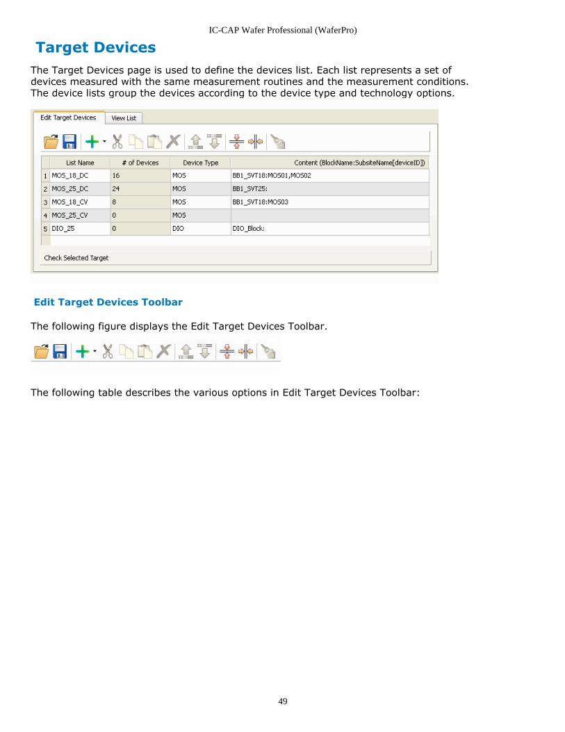
Target DevicesThe Target Devices page is used to define the devices list. Each list represents a set ofdevices measured with the same measurement routines and the measurement conditions.The device lists group the devices according to the device type and technology options.
Edit Target Devices Toolbar
The following figure displays the Edit Target Devices Toolbar.
The following table describes the various options in Edit Target Devices Toolbar:
IC-CAP Wafer Professional (WaferPro)
50
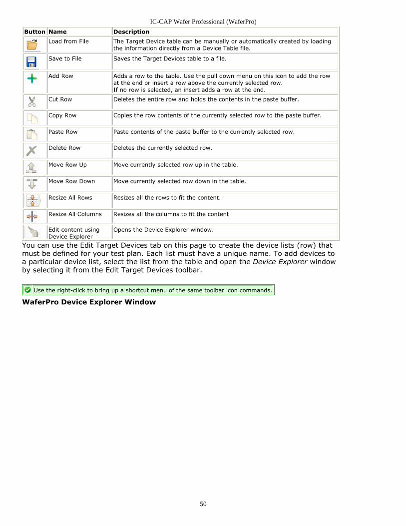
Button Name Description
Load from File The Target Device table can be manually or automatically created by loadingthe information directly from a Device Table file.
Save to File Saves the Target Devices table to a file.
Add Row Adds a row to the table. Use the pull down menu on this icon to add the rowat the end or insert a row above the currently selected row.If no row is selected, an insert adds a row at the end.
Cut Row Deletes the entire row and holds the contents in the paste buffer.
Copy Row Copies the row contents of the currently selected row to the paste buffer.
Paste Row Paste contents of the paste buffer to the currently selected row.
Delete Row Deletes the currently selected row.
Move Row Up Move currently selected row up in the table.
Move Row Down Move currently selected row down in the table.
Resize All Rows Resizes all the rows to fit the content.
Resize All Columns Resizes all the columns to fit the content
Edit content usingDevice Explorer
Opens the Device Explorer window.
You can use the Edit Target Devices tab on this page to create the device lists (row) thatmust be defined for your test plan. Each list must have a unique name. To add devices toa particular device list, select the list from the table and open the Device Explorer windowby selecting it from the Edit Target Devices toolbar.
Use the right-click to bring up a shortcut menu of the same toolbar icon commands.
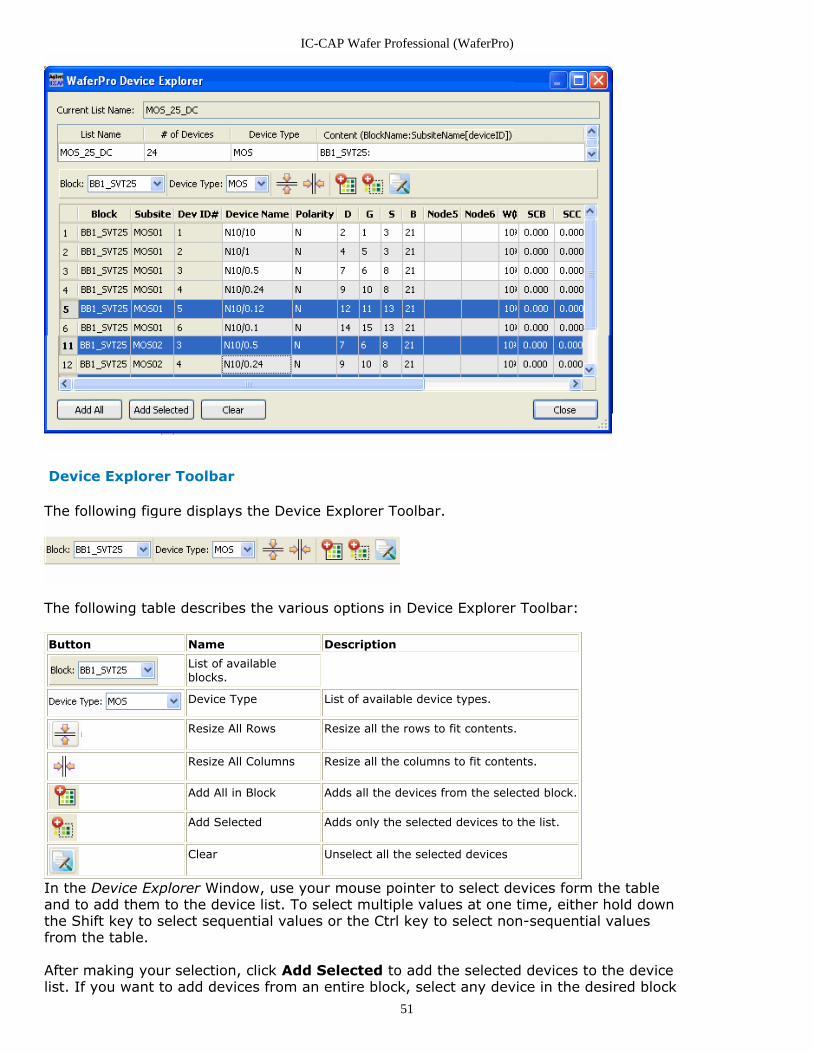
WaferPro Device Explorer Window
IC-CAP Wafer Professional (WaferPro)
51
Device Explorer Toolbar
The following figure displays the Device Explorer Toolbar.
The following table describes the various options in Device Explorer Toolbar:
Button Name Description
List of availableblocks.
Device Type List of available device types.
Resize All Rows Resize all the rows to fit contents.
Resize All Columns Resize all the columns to fit contents.
Add All in Block Adds all the devices from the selected block.
Add Selected Adds only the selected devices to the list.
Clear Unselect all the selected devices
In the Device Explorer Window, use your mouse pointer to select devices form the tableand to add them to the device list. To select multiple values at one time, either hold downthe Shift key to select sequential values or the Ctrl key to select non-sequential valuesfrom the table.
After making your selection, click Add Selected to add the selected devices to the devicelist. If you want to add devices from an entire block, select any device in the desired block
IC-CAP Wafer Professional (WaferPro)
52
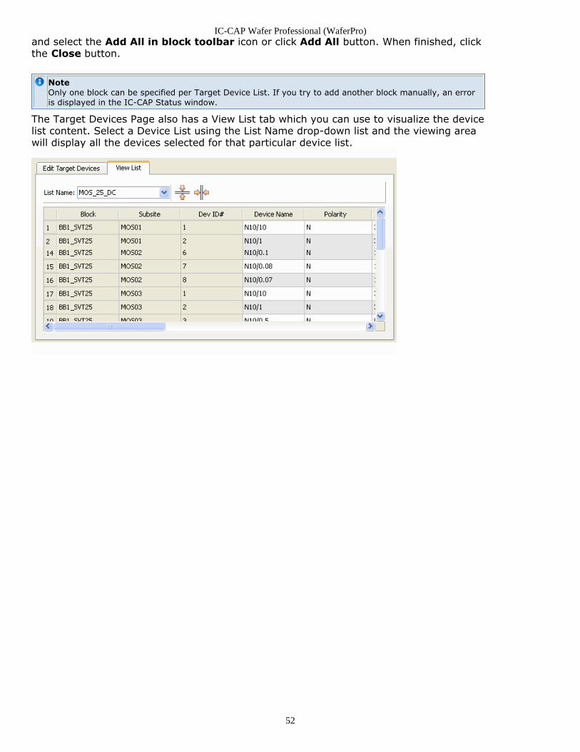
and select the Add All in block toolbar icon or click Add All button. When finished, clickthe Close button.
NoteOnly one block can be specified per Target Device List. If you try to add another block manually, an erroris displayed in the IC-CAP Status window.
The Target Devices Page also has a View List tab which you can use to visualize the devicelist content. Select a Device List using the List Name drop-down list and the viewing areawill display all the devices selected for that particular device list.
IC-CAP Wafer Professional (WaferPro)
53
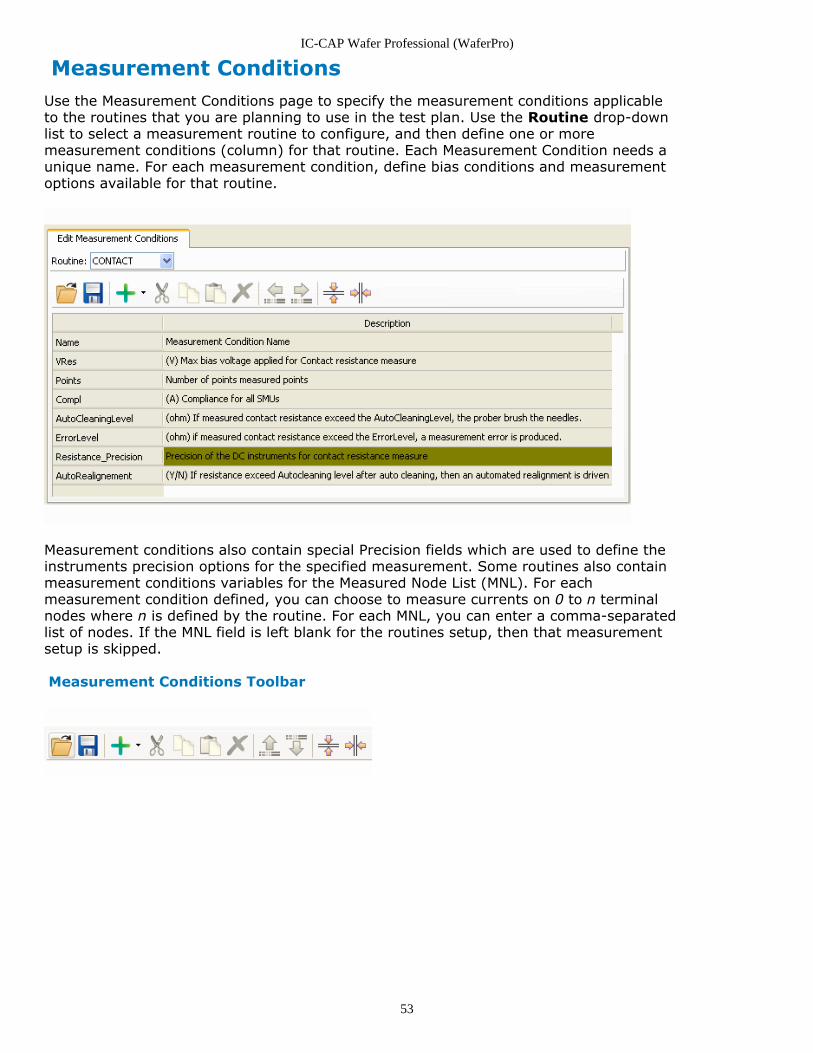
Measurement ConditionsUse the Measurement Conditions page to specify the measurement conditions applicableto the routines that you are planning to use in the test plan. Use the Routine drop-downlist to select a measurement routine to configure, and then define one or moremeasurement conditions (column) for that routine. Each Measurement Condition needs aunique name. For each measurement condition, define bias conditions and measurementoptions available for that routine.
Measurement conditions also contain special Precision fields which are used to define theinstruments precision options for the specified measurement. Some routines also containmeasurement conditions variables for the Measured Node List (MNL). For eachmeasurement condition defined, you can choose to measure currents on 0 to n terminalnodes where n is defined by the routine. For each MNL, you can enter a comma-separatedlist of nodes. If the MNL field is left blank for the routines setup, then that measurementsetup is skipped.
Measurement Conditions Toolbar
IC-CAP Wafer Professional (WaferPro)
54
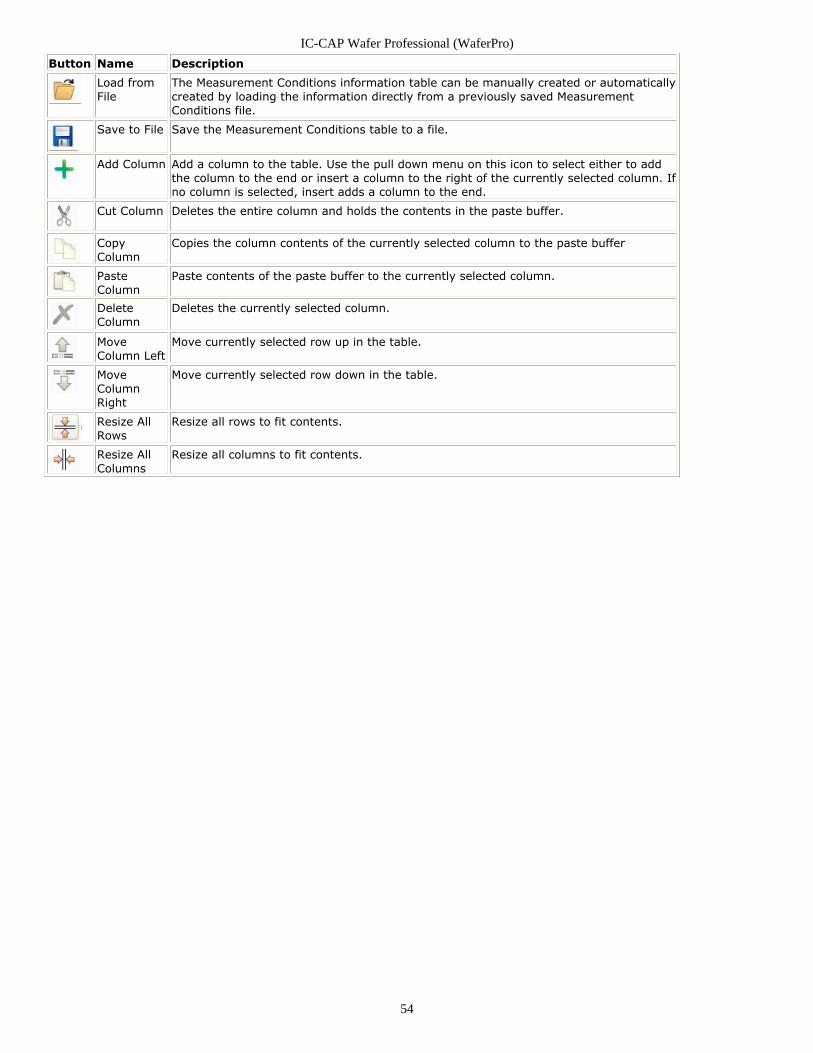
Button Name Description
Load fromFile
The Measurement Conditions information table can be manually created or automaticallycreated by loading the information directly from a previously saved MeasurementConditions file.
Save to File Save the Measurement Conditions table to a file.
Add Column Add a column to the table. Use the pull down menu on this icon to select either to addthe column to the end or insert a column to the right of the currently selected column. Ifno column is selected, insert adds a column to the end.
Cut Column Deletes the entire column and holds the contents in the paste buffer.
CopyColumn
Copies the column contents of the currently selected column to the paste buffer
PasteColumn
Paste contents of the paste buffer to the currently selected column.
DeleteColumn
Deletes the currently selected column.
MoveColumn Left
Move currently selected row up in the table.
MoveColumnRight
Move currently selected row down in the table.
Resize AllRows
Resize all rows to fit contents.
Resize AllColumns
Resize all columns to fit contents.
IC-CAP Wafer Professional (WaferPro)
55
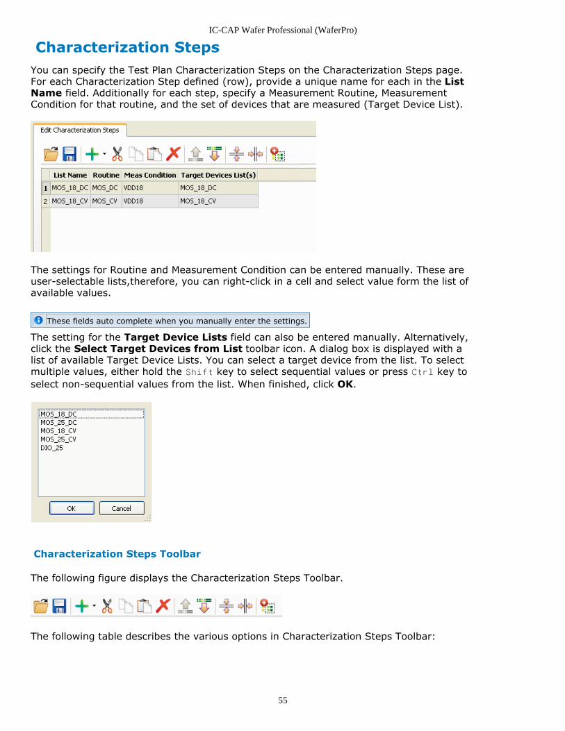
Characterization StepsYou can specify the Test Plan Characterization Steps on the Characterization Steps page.For each Characterization Step defined (row), provide a unique name for each in the ListName field. Additionally for each step, specify a Measurement Routine, MeasurementCondition for that routine, and the set of devices that are measured (Target Device List).
The settings for Routine and Measurement Condition can be entered manually. These areuser-selectable lists,therefore, you can right-click in a cell and select value form the list ofavailable values.
These fields auto complete when you manually enter the settings.
The setting for the Target Device Lists field can also be entered manually. Alternatively,click the Select Target Devices from List toolbar icon. A dialog box is displayed with alist of available Target Device Lists. You can select a target device from the list. To selectmultiple values, either hold the Shift key to select sequential values or press Ctrl key toselect non-sequential values from the list. When finished, click OK.
Characterization Steps Toolbar
The following figure displays the Characterization Steps Toolbar.
The following table describes the various options in Characterization Steps Toolbar:
IC-CAP Wafer Professional (WaferPro)
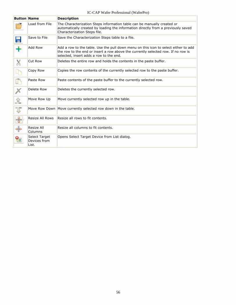
56
Button Name Description
Load from File The Characterization Steps information table can be manually created orautomatically created by loading the information directly from a previously savedCharacterization Steps file.
Save to File Save the Characterization Steps table to a file.
Add Row Add a row to the table. Use the pull down menu on this icon to select either to addthe row to the end or insert a row above the currently selected row. If no row isselected, insert adds a row to the end.
Cut Row Deletes the entire row and holds the contents in the paste buffer.
Copy Row Copies the row contents of the currently selected row to the paste buffer.
Paste Row Paste contents of the paste buffer to the currently selected row.
Delete Row Deletes the currently selected row.
Move Row Up Move currently selected row up in the table.
Move Row Down Move currently selected row down in the table.
Resize All Rows Resize all rows to fit contents.
Resize AllColumns
Resize all columns to fit contents.
Select TargetDevices fromList.
Opens Select Target Device from List dialog.
IC-CAP Wafer Professional (WaferPro)
57
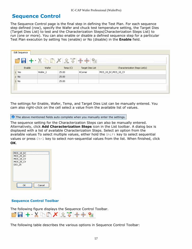
Sequence ControlThe Sequence Control page is the final step in defining the Test Plan. For each sequencestep defined (row), specify the Wafer and chuck test temperature setting, the Target Dies(Target Dies List) to test and the Characterization Steps(Characterization Steps List) torun (one or more). You can also enable or disable a defined sequence step for a particularTest Plan execution by setting Yes (enable) or No (disable) in the Enable field.
The settings for Enable, Wafer, Temp, and Target Dies List can be manually entered. Youcam also right-click on the cell select a value from the available list of values.
The above mentioned fields auto complete when you manually enter the settings.
The sequence setting for the Characterization Steps can also be manually entered.Alternatively, click Add Characterization Steps icon in the List toolbar. A dialog box isdisplayed with a list of available Characterization Steps. Select an option from theavailable values To select multiple values, either hold the Shift key to select sequentialvalues or press Ctrl key to select non-sequential values from the list. When finished, clickOK.
Sequence Control Toolbar
The following figure displays the Sequence Control Toolbar.
The following table describes the various options in Sequence Control Toolbar:
IC-CAP Wafer Professional (WaferPro)
58
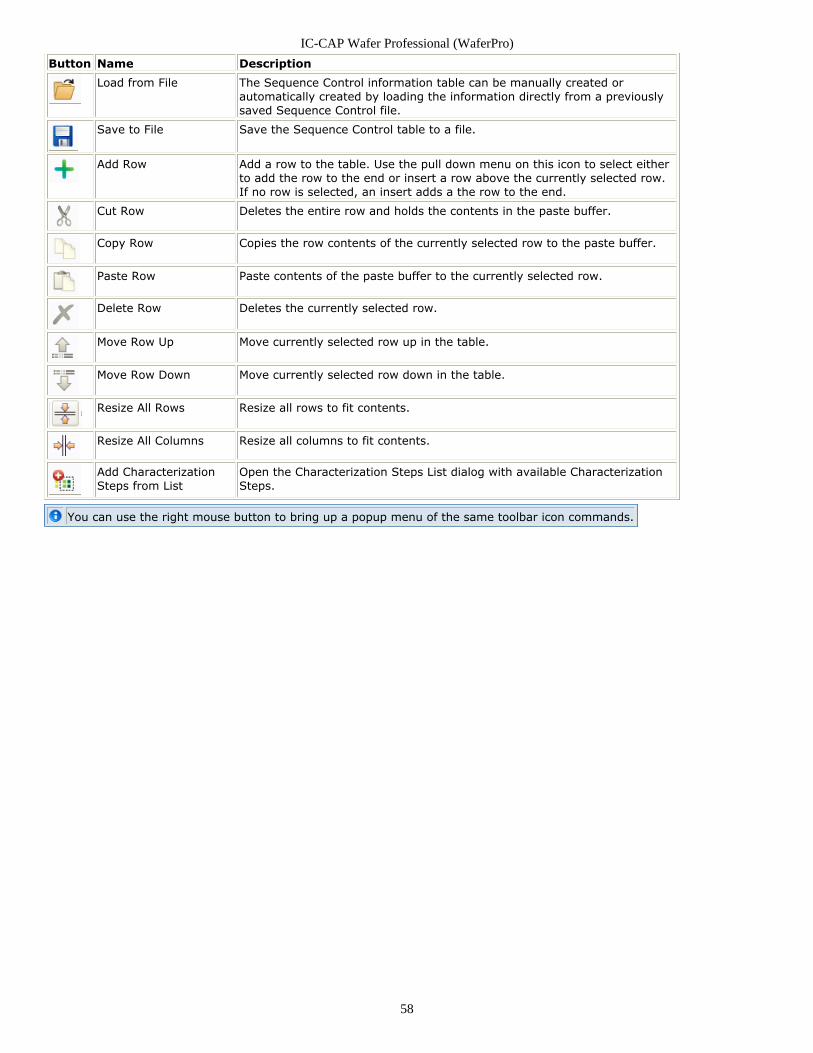
Button Name Description
Load from File The Sequence Control information table can be manually created orautomatically created by loading the information directly from a previouslysaved Sequence Control file.
Save to File Save the Sequence Control table to a file.
Add Row Add a row to the table. Use the pull down menu on this icon to select eitherto add the row to the end or insert a row above the currently selected row.If no row is selected, an insert adds a the row to the end.
Cut Row Deletes the entire row and holds the contents in the paste buffer.
Copy Row Copies the row contents of the currently selected row to the paste buffer.
Paste Row Paste contents of the paste buffer to the currently selected row.
Delete Row Deletes the currently selected row.
Move Row Up Move currently selected row up in the table.
Move Row Down Move currently selected row down in the table.
Resize All Rows Resize all rows to fit contents.
Resize All Columns Resize all columns to fit contents.
Add CharacterizationSteps from List
Open the Characterization Steps List dialog with available CharacterizationSteps.
You can use the right mouse button to bring up a popup menu of the same toolbar icon commands.
IC-CAP Wafer Professional (WaferPro)
59
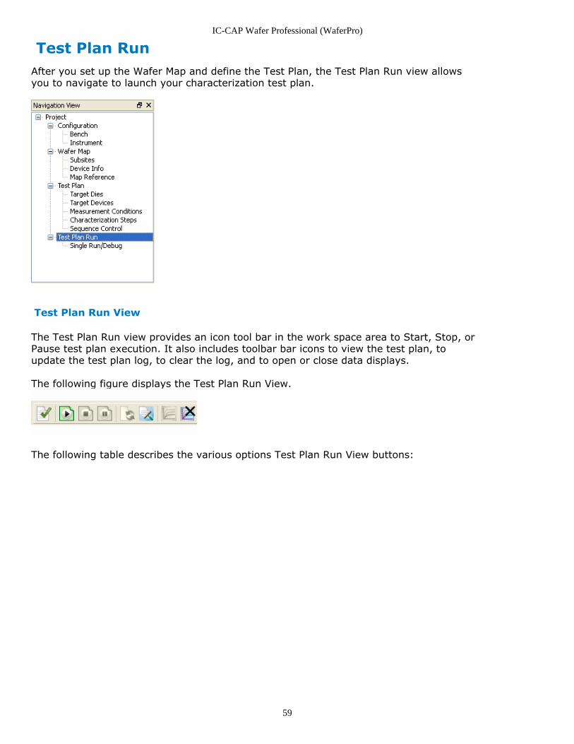
Test Plan RunAfter you set up the Wafer Map and define the Test Plan, the Test Plan Run view allowsyou to navigate to launch your characterization test plan.
Test Plan Run View
The Test Plan Run view provides an icon tool bar in the work space area to Start, Stop, orPause test plan execution. It also includes toolbar bar icons to view the test plan, toupdate the test plan log, to clear the log, and to open or close data displays.
The following figure displays the Test Plan Run View.
The following table describes the various options Test Plan Run View buttons:
IC-CAP Wafer Professional (WaferPro)
60
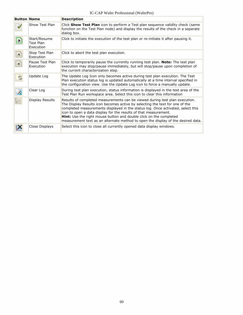
Button Name Description
Show Test Plan Click Show Test Plan icon to perform a Test plan sequence validity check (samefunction on the Test Plan node) and display the results of the check in a separatedialog box.
Start/ResumeTest PlanExecution
Click to initiate the execution of the test plan or re-initiate it after pausing it.
Stop Test PlanExecution
Click to abort the test plan execution.
Pause Test PlanExecution
Click to temporarily pause the currently running test plan. Note: The test planexecution may stop/pause immediately, but will stop/pause upon completion ofthe current characterization step.
Update Log The Update Log Icon only becomes active during test plan execution. The TestPlan execution status log is updated automatically at a time interval specified inthe configuration view. Use the Update Log icon to force a manually update.
Clear Log During test plan execution, status information is displayed in the test area of theTest Plan Run workspace area. Select this icon to clear this information
Display Results Results of completed measurements can be viewed during test plan execution.The Display Results icon becomes active by selecting the text for one of thecompleted measurements displayed in the status log. Once activated, select thisicon to open a data display for the results of that measurement.Hint: Use the right mouse button and double click on the completedmeasurement text as an alternate method to open the display of the desired data.
Close Displays Select this icon to close all currently opened data display windows.
IC-CAP Wafer Professional (WaferPro)
61
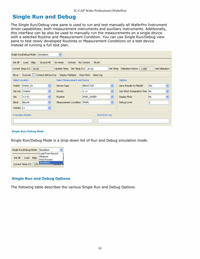
Single Run and DebugThe Single Run/Debug view pane is used to run and test manually all WaferPro Instrumentdriver capabilities; both measurement instruments and auxiliary instruments. Additionally,this interface can be also be used to manually run the measurements on a single devicewith a selected Routine and Measurement Condition. You can use Single Run/Debug viewpane to test newly developed Routines or Measurement Conditions on a test deviceinstead of running a full test plan.
Single Run/Debug Mode
Single Run/Debug Mode is a drop-down list of Run and Debug simulation mode.
Single Run and Debug Options
The following table describes the various Single Run and Debug Options.
IC-CAP Wafer Professional (WaferPro)
62
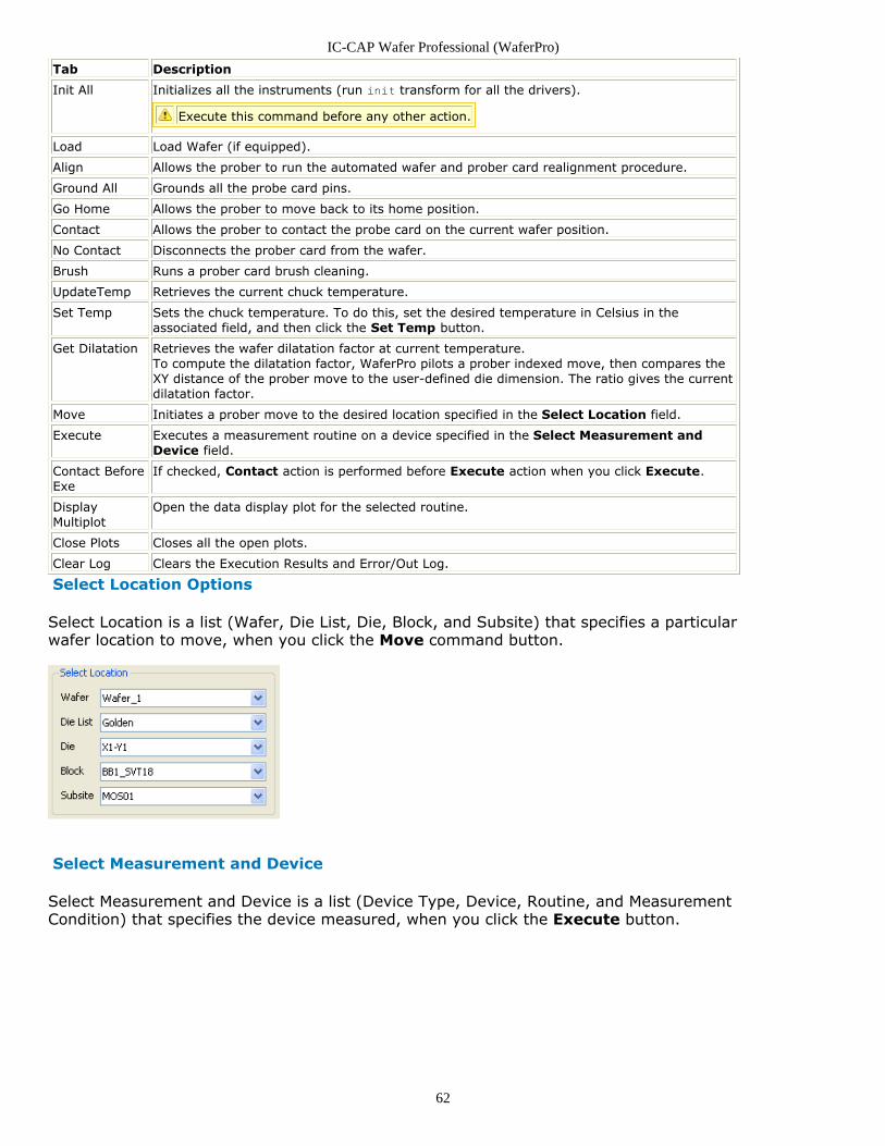
Tab Description
Init All Initializes all the instruments (run init transform for all the drivers).
Execute this command before any other action.
Load Load Wafer (if equipped).
Align Allows the prober to run the automated wafer and prober card realignment procedure.
Ground All Grounds all the probe card pins.
Go Home Allows the prober to move back to its home position.
Contact Allows the prober to contact the probe card on the current wafer position.
No Contact Disconnects the prober card from the wafer.
Brush Runs a prober card brush cleaning.
UpdateTemp Retrieves the current chuck temperature.
Set Temp Sets the chuck temperature. To do this, set the desired temperature in Celsius in theassociated field, and then click the Set Temp button.
Get Dilatation Retrieves the wafer dilatation factor at current temperature.To compute the dilatation factor, WaferPro pilots a prober indexed move, then compares theXY distance of the prober move to the user-defined die dimension. The ratio gives the currentdilatation factor.
Move Initiates a prober move to the desired location specified in the Select Location field.
Execute Executes a measurement routine on a device specified in the Select Measurement andDevice field.
Contact BeforeExe
If checked, Contact action is performed before Execute action when you click Execute.
DisplayMultiplot
Open the data display plot for the selected routine.
Close Plots Closes all the open plots.
Clear Log Clears the Execution Results and Error/Out Log.
Select Location Options
Select Location is a list (Wafer, Die List, Die, Block, and Subsite) that specifies a particularwafer location to move, when you click the Move command button.
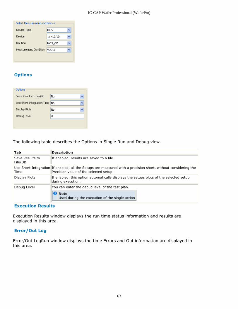
Select Measurement and Device
Select Measurement and Device is a list (Device Type, Device, Routine, and MeasurementCondition) that specifies the device measured, when you click the Execute button.
IC-CAP Wafer Professional (WaferPro)
63
Options
The following table describes the Options in Single Run and Debug view.
Tab Description
Save Results toFile/DB
If enabled, results are saved to a file.
Use Short IntegrationTime
If enabled, all the Setups are measured with a precision short, without considering thePrecision value of the selected setup.
Display Plots If enabled, this option automatically displays the setups plots of the selected setupduring execution.
Debug Level You can enter the debug level of the test plan.
NoteUsed during the execution of the single action
Execution Results
Execution Results window displays the run time status information and results aredisplayed in this area.
Error/Out Log
Error/Out LogRun window displays the time Errors and Out information are displayed inthis area.

IC-CAP Wafer Professional (WaferPro)
64
Getting Started with WaferProThis section provides information on the following topics:
Starting WaferPro (waferpro)Managing WaferPro Projects (waferpro)An Example WaferPro Session (waferpro)Preparing For Real Measurements (waferpro)
IC-CAP Wafer Professional (WaferPro)
65
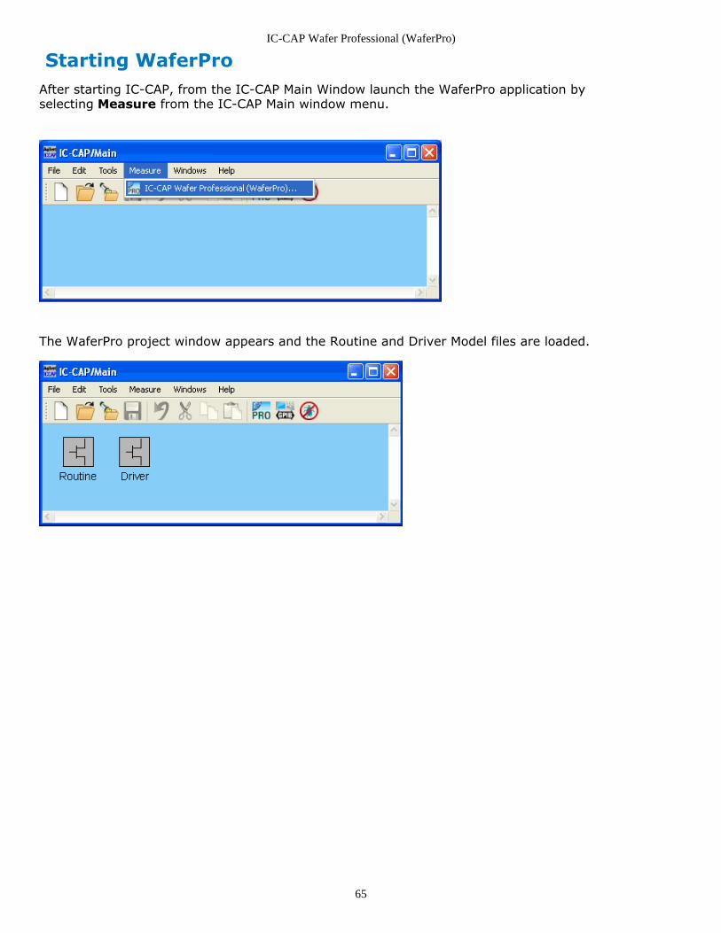
Starting WaferProAfter starting IC-CAP, from the IC-CAP Main Window launch the WaferPro application byselecting Measure from the IC-CAP Main window menu.
The WaferPro project window appears and the Routine and Driver Model files are loaded.
IC-CAP Wafer Professional (WaferPro)
66
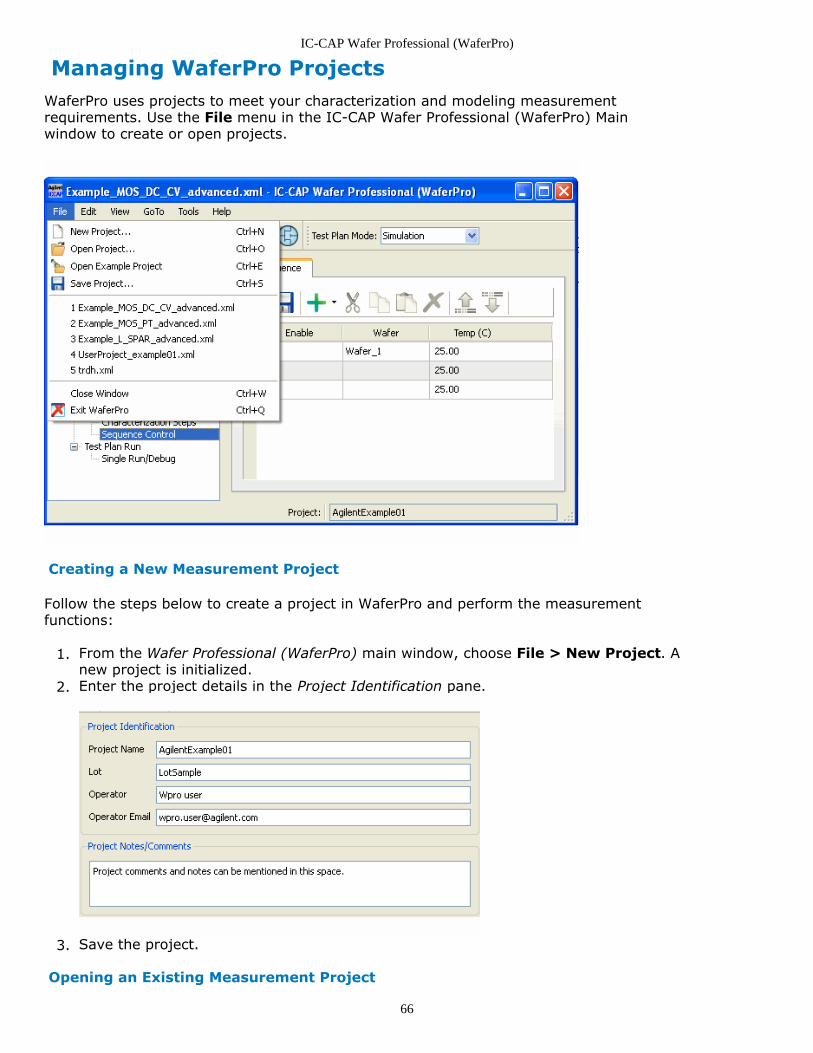
Managing WaferPro ProjectsWaferPro uses projects to meet your characterization and modeling measurementrequirements. Use the File menu in the IC-CAP Wafer Professional (WaferPro) Mainwindow to create or open projects.
Creating a New Measurement Project
Follow the steps below to create a project in WaferPro and perform the measurementfunctions:
From the Wafer Professional (WaferPro) main window, choose File > New Project. A1.new project is initialized.Enter the project details in the Project Identification pane.2.
Save the project.3.
Opening an Existing Measurement Project
IC-CAP Wafer Professional (WaferPro)
67
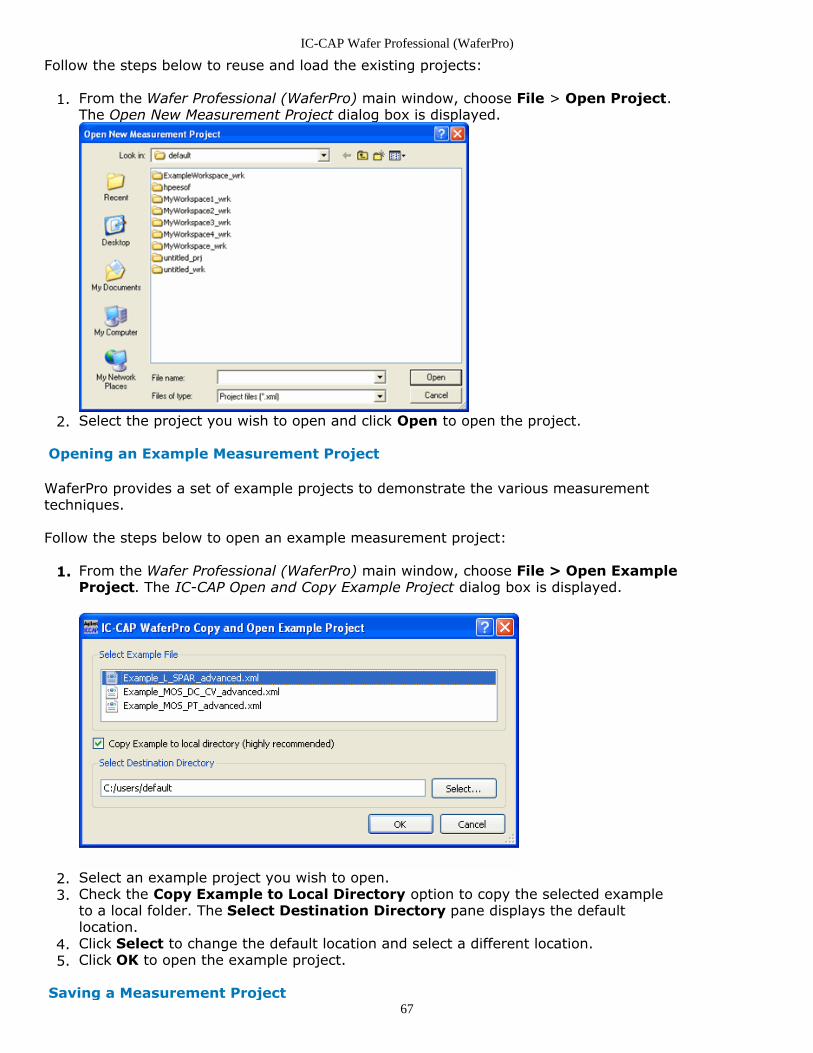
Follow the steps below to reuse and load the existing projects:
From the Wafer Professional (WaferPro) main window, choose File > Open Project.1.The Open New Measurement Project dialog box is displayed.
Select the project you wish to open and click Open to open the project.2.
Opening an Example Measurement Project
WaferPro provides a set of example projects to demonstrate the various measurementtechniques.
Follow the steps below to open an example measurement project:
From the Wafer Professional (WaferPro) main window, choose File > Open Example1.Project. The IC-CAP Open and Copy Example Project dialog box is displayed.
Select an example project you wish to open.2.Check the Copy Example to Local Directory option to copy the selected example3.to a local folder. The Select Destination Directory pane displays the defaultlocation.Click Select to change the default location and select a different location.4.Click OK to open the example project.5.
Saving a Measurement Project
IC-CAP Wafer Professional (WaferPro)
68
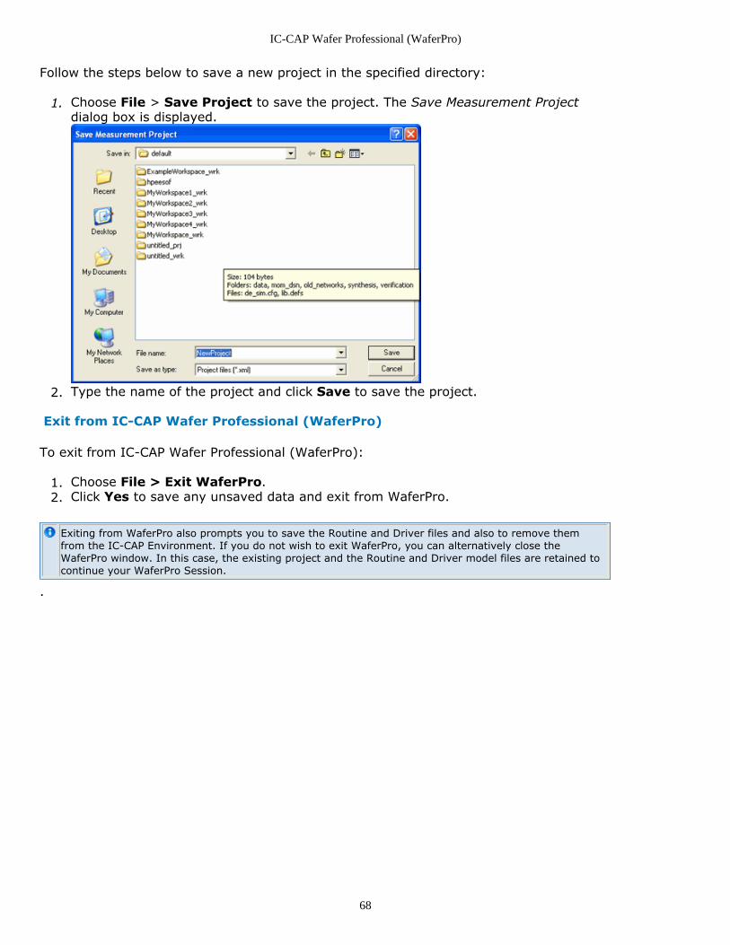
Follow the steps below to save a new project in the specified directory:
Choose File > Save Project to save the project. The Save Measurement Project1.dialog box is displayed.
Type the name of the project and click Save to save the project.2.
Exit from IC-CAP Wafer Professional (WaferPro)
To exit from IC-CAP Wafer Professional (WaferPro):
Choose File > Exit WaferPro.1.Click Yes to save any unsaved data and exit from WaferPro.2.
Exiting from WaferPro also prompts you to save the Routine and Driver files and also to remove themfrom the IC-CAP Environment. If you do not wish to exit WaferPro, you can alternatively close theWaferPro window. In this case, the existing project and the Routine and Driver model files are retained tocontinue your WaferPro Session.
.
IC-CAP Wafer Professional (WaferPro)
69
An Example WaferPro SessionUsing WaferPro, you can measure a test project by following this procedure:
Start the IC-CAP Wafer ProfessionalLoad an example test project and make a local copy of the example project file.Update the Data Storage Path.Run the Test Plan.View the Test Plan Log.
This section provides an example of a WaferPro session, using an example test project.
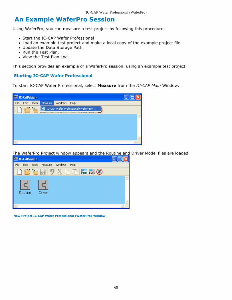
Starting IC-CAP Wafer Professional
To start IC-CAP Wafer Professional, select Measure from the IC-CAP Main Window.
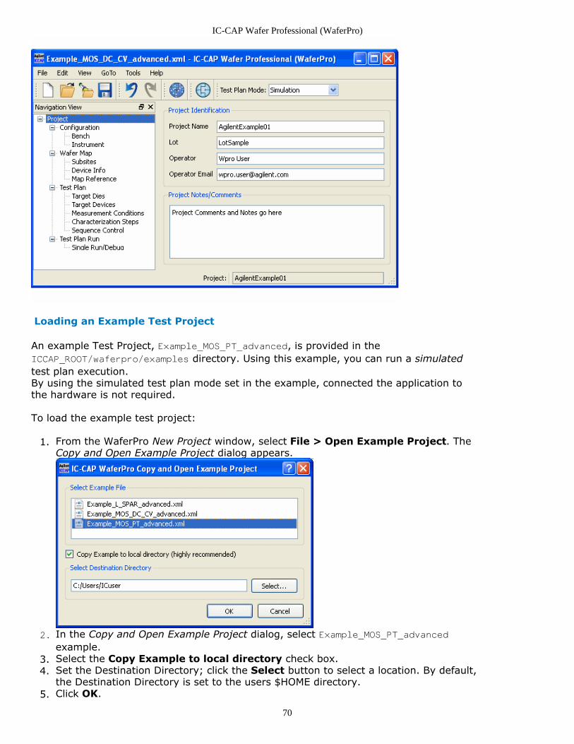
The WaferPro Project window appears and the Routine and Driver Model files are loaded.
New Project IC-CAP Wafer Professional (WaferPro) Window
IC-CAP Wafer Professional (WaferPro)
70
Loading an Example Test Project
An example Test Project, Example_MOS_PT_advanced, is provided in theICCAP_ROOT/waferpro/examples directory. Using this example, you can run a simulatedtest plan execution.By using the simulated test plan mode set in the example, connected the application tothe hardware is not required.
To load the example test project:
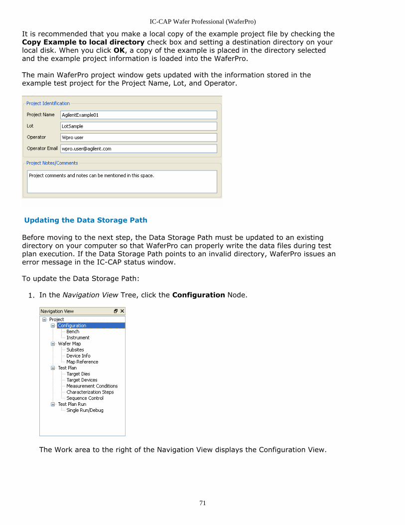
From the WaferPro New Project window, select File > Open Example Project. The1.Copy and Open Example Project dialog appears.
In the Copy and Open Example Project dialog, select Example_MOS_PT_advanced2.
example.Select the Copy Example to local directory check box.3.Set the Destination Directory; click the Select button to select a location. By default,4.the Destination Directory is set to the users $HOME directory.Click OK.5.
IC-CAP Wafer Professional (WaferPro)
71
It is recommended that you make a local copy of the example project file by checking theCopy Example to local directory check box and setting a destination directory on yourlocal disk. When you click OK, a copy of the example is placed in the directory selectedand the example project information is loaded into the WaferPro.
The main WaferPro project window gets updated with the information stored in theexample test project for the Project Name, Lot, and Operator.
Updating the Data Storage Path
Before moving to the next step, the Data Storage Path must be updated to an existingdirectory on your computer so that WaferPro can properly write the data files during testplan execution. If the Data Storage Path points to an invalid directory, WaferPro issues anerror message in the IC-CAP status window.
To update the Data Storage Path:
In the Navigation View Tree, click the Configuration Node.1.
The Work area to the right of the Navigation View displays the Configuration View.
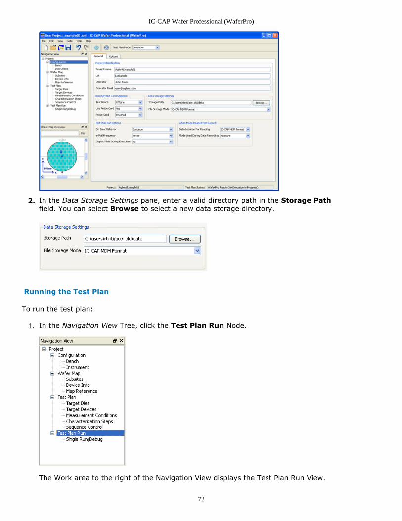
IC-CAP Wafer Professional (WaferPro)
72
In the Data Storage Settings pane, enter a valid directory path in the Storage Path2.field. You can select Browse to select a new data storage directory.
Running the Test Plan
To run the test plan:
In the Navigation View Tree, click the Test Plan Run Node.1.
The Work area to the right of the Navigation View displays the Test Plan Run View.
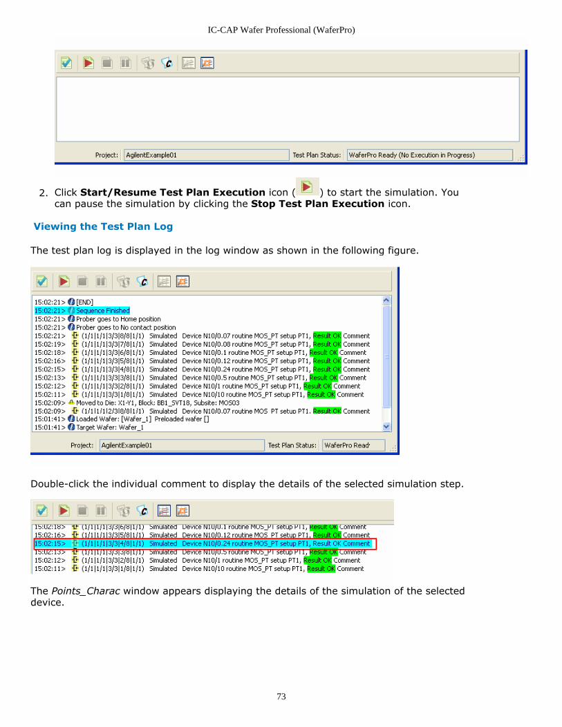
IC-CAP Wafer Professional (WaferPro)
73
Click Start/Resume Test Plan Execution icon ( ) to start the simulation. You2.can pause the simulation by clicking the Stop Test Plan Execution icon.
Viewing the Test Plan Log
The test plan log is displayed in the log window as shown in the following figure.
Double-click the individual comment to display the details of the selected simulation step.
The Points_Charac window appears displaying the details of the simulation of the selecteddevice.
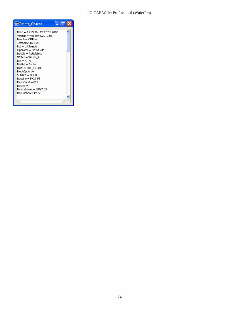
IC-CAP Wafer Professional (WaferPro)
74
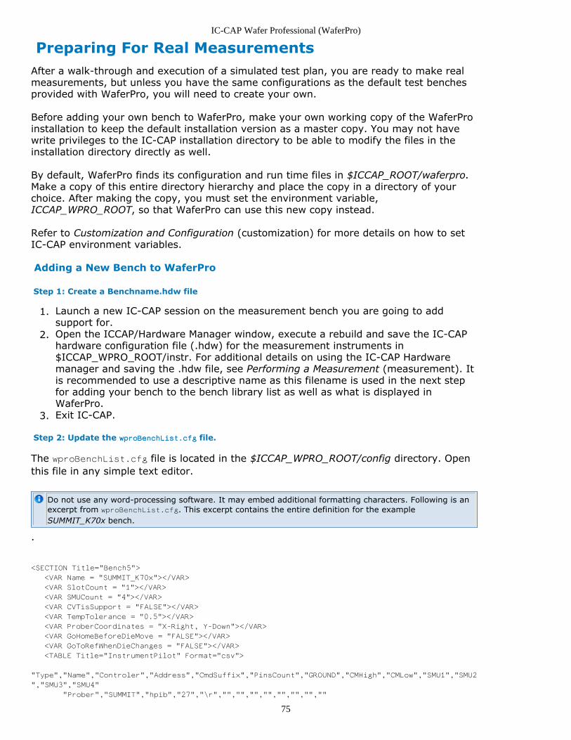
IC-CAP Wafer Professional (WaferPro)
75
Preparing For Real MeasurementsAfter a walk-through and execution of a simulated test plan, you are ready to make realmeasurements, but unless you have the same configurations as the default test benchesprovided with WaferPro, you will need to create your own.
Before adding your own bench to WaferPro, make your own working copy of the WaferProinstallation to keep the default installation version as a master copy. You may not havewrite privileges to the IC-CAP installation directory to be able to modify the files in theinstallation directory directly as well.
By default, WaferPro finds its configuration and run time files in $ICCAP_ROOT/waferpro.Make a copy of this entire directory hierarchy and place the copy in a directory of yourchoice. After making the copy, you must set the environment variable,ICCAP_WPRO_ROOT, so that WaferPro can use this new copy instead.
Refer to Customization and Configuration (customization) for more details on how to setIC-CAP environment variables.
Adding a New Bench to WaferPro
Step 1: Create a Benchname.hdw file
Launch a new IC-CAP session on the measurement bench you are going to add1.support for.Open the ICCAP/Hardware Manager window, execute a rebuild and save the IC-CAP2.hardware configuration file (.hdw) for the measurement instruments in$ICCAP_WPRO_ROOT/instr. For additional details on using the IC-CAP Hardwaremanager and saving the .hdw file, see Performing a Measurement (measurement). Itis recommended to use a descriptive name as this filename is used in the next stepfor adding your bench to the bench library list as well as what is displayed inWaferPro.Exit IC-CAP.3.
Step 2: Update the wproBenchList.cfg file.
The wproBenchList.cfg file is located in the $ICCAP_WPRO_ROOT/config directory. Openthis file in any simple text editor.
Do not use any word-processing software. It may embed additional formatting characters. Following is anexcerpt from wproBenchList.cfg. This excerpt contains the entire definition for the exampleSUMMIT_K70x bench.
.
<SECTION Title="Bench5">
<VAR Name = "SUMMIT_K70x"></VAR>
<VAR SlotCount = "1"></VAR>
<VAR SMUCount = "4"></VAR>
<VAR CVTisSupport = "FALSE"></VAR>
<VAR TempTolerance = "0.5"></VAR>
<VAR ProberCoordinates = "X-Right, Y-Down"></VAR>
<VAR GoHomeBeforeDieMove = "FALSE"></VAR>
<VAR GoToRefWhenDieChanges = "FALSE"></VAR>
<TABLE Title="InstrumentPilot" Format="csv">
"Type","Name","Controler","Address","CmdSuffix","PinsCount","GROUND","CMHigh","CMLow","SMU1","SMU2
","SMU3","SMU4"
"Prober","SUMMIT","hpib","27","\r","","","","","","","",""
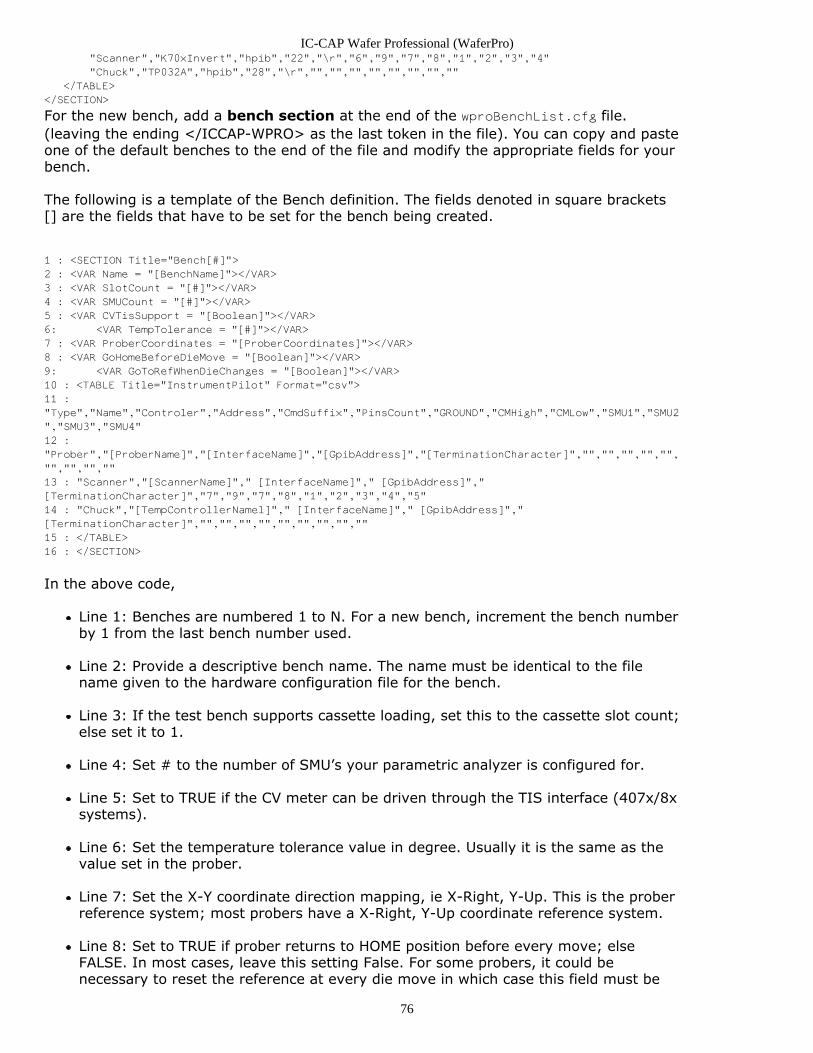
IC-CAP Wafer Professional (WaferPro)
76
"Scanner","K70xInvert","hpib","22","\r","6","9","7","8","1","2","3","4"
"Chuck","TP032A","hpib","28","\r","","","","","","","",""
</TABLE>
</SECTION>
For the new bench, add a bench section at the end of the wproBenchList.cfg file.(leaving the ending </ICCAP-WPRO> as the last token in the file). You can copy and pasteone of the default benches to the end of the file and modify the appropriate fields for yourbench.
The following is a template of the Bench definition. The fields denoted in square brackets[] are the fields that have to be set for the bench being created.
1 : <SECTION Title="Bench[#]">
2 : <VAR Name = "[BenchName]"></VAR>
3 : <VAR SlotCount = "[#]"></VAR>
4 : <VAR SMUCount = "[#]"></VAR>
5 : <VAR CVTisSupport = "[Boolean]"></VAR>
6: <VAR TempTolerance = "[#]"></VAR>
7 : <VAR ProberCoordinates = "[ProberCoordinates]"></VAR>
8 : <VAR GoHomeBeforeDieMove = "[Boolean]"></VAR>
9: <VAR GoToRefWhenDieChanges = "[Boolean]"></VAR>
10 : <TABLE Title="InstrumentPilot" Format="csv">
11 :
"Type","Name","Controler","Address","CmdSuffix","PinsCount","GROUND","CMHigh","CMLow","SMU1","SMU2
","SMU3","SMU4"
12 :
"Prober","[ProberName]","[InterfaceName]","[GpibAddress]","[TerminationCharacter]","","","","","",
"","","",""
13 : "Scanner","[ScannerName]"," [InterfaceName]"," [GpibAddress]","
[TerminationCharacter]","7","9","7","8","1","2","3","4","5"
14 : "Chuck","[TempControllerNamel]"," [InterfaceName]"," [GpibAddress]","
[TerminationCharacter]","","","","","","","","",""
15 : </TABLE>
16 : </SECTION>
In the above code,
Line 1: Benches are numbered 1 to N. For a new bench, increment the bench numberby 1 from the last bench number used.
Line 2: Provide a descriptive bench name. The name must be identical to the filename given to the hardware configuration file for the bench.
Line 3: If the test bench supports cassette loading, set this to the cassette slot count;else set it to 1.
Line 4: Set # to the number of SMU’s your parametric analyzer is configured for.
Line 5: Set to TRUE if the CV meter can be driven through the TIS interface (407x/8xsystems).
Line 6: Set the temperature tolerance value in degree. Usually it is the same as thevalue set in the prober.
Line 7: Set the X-Y coordinate direction mapping, ie X-Right, Y-Up. This is the proberreference system; most probers have a X-Right, Y-Up coordinate reference system.
Line 8: Set to TRUE if prober returns to HOME position before every move; elseFALSE. In most cases, leave this setting False. For some probers, it could benecessary to reset the reference at every die move in which case this field must be
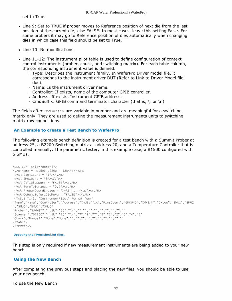
IC-CAP Wafer Professional (WaferPro)
77
set to True.
Line 9: Set to TRUE if prober moves to Reference position of next die from the lastposition of the current die; else FALSE. In most cases, leave this setting False. Forsome probers it may go to Reference position of dies automatically when changingdies in which case this field should be set to True.
Line 10: No modifications.
Line 11-12: The instrument pilot table is used to define configuration of contextcontrol instruments (prober, chuck, and switching matrix). For each table column,the corresponding instrument value is defined.
Type: Describes the instrument family. In WaferPro Driver model file, itcorresponds to the instrument driver DUT (Refer to Link to Driver Model filedoc).Name: Is the instrument driver name.Controller: If exists, name of the computer GPIB controller.Address: If exists, Instrument GPIB address.CmdSuffix: GPIB command terminator character (that is, \r or \n).
The fields after CmdSuffix are variable in number and are meaningful for a switchingmatrix only. They are used to define the measurement instruments units to switchingmatrix row connections.
An Example to create a Test Bench to WaferPro
The following example bench definition is created for a test bench with a Summit Prober ataddress 25, a B2200 Switching matrix at address 20, and a Temperature Controller that iscontrolled manually. The parametric tester, in this example case, a B1500 configured with5 SMUs.
<SECTION Title="Bench7">
<VAR Name = "B1500_B2200_HP4284"></VAR>
<VAR SlotCount = "1"></VAR>
<VAR SMUCount = "5"></VAR>
<VAR CVTisSupport = "FALSE"></VAR>
<VAR TempTolerance = "0.5"></VAR>
<VAR ProberCoordinates = "X-Right, Y-Up"></VAR>
<VAR GoHomeBeforeDieMove = "FALSE"></VAR>
<TABLE Title="InstrumentPilot" Format="csv">
"Type","Name","Controler","Address","CmdSuffix","PinsCount","GROUND","CMHigh","CMLow","SMU1","SMU2
","SMU3","SMU4","SMU5"
"Prober","SUMMIT","hpib","25","\r","","","","","","","","",""
"Scanner","B2200","hpib","20","\r","7","9","7","8","1","2","3","4","5"
"Chuck","Manual","None","None","","","","","","","","","",""
</TABLE>
</SECTION>
Updating the [Precision].iot files.
This step is only required if new measurement instruments are being added to your newbench.
Using the New Bench
After completing the previous steps and placing the new files, you should be able to useyour new bench.
To use the New Bench:
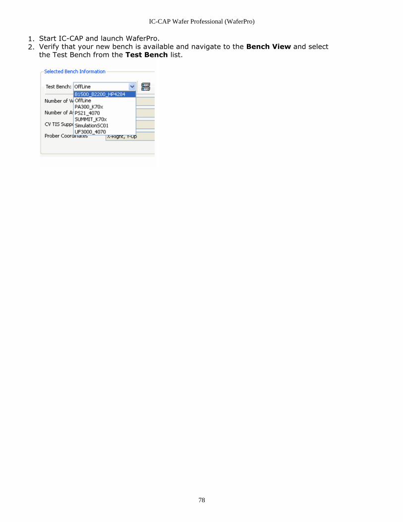
IC-CAP Wafer Professional (WaferPro)
78
Start IC-CAP and launch WaferPro.1.Verify that your new bench is available and navigate to the Bench View and select2.the Test Bench from the Test Bench list.
IC-CAP Wafer Professional (WaferPro)
79
About WaferPro Measurement andRoutine FilesThis section provides information on the following topics:
About Measurement Routine File (waferpro)About WaferPro Routine (waferpro)Creating a Routine for WaferPro (waferpro)PEL Functions (waferpro)Test Plan Execution Flow (waferpro)Controlling WaferPro via IC-CAP PEL (waferpro)
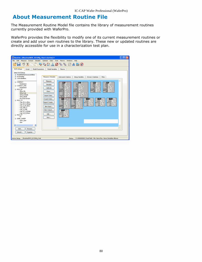
IC-CAP Wafer Professional (WaferPro)
80
About Measurement Routine FileThe Measurement Routine Model file contains the library of measurement routinescurrently provided with WaferPro.
WaferPro provides the flexibility to modify one of its current measurement routines orcreate and add your own routines to the library. These new or updated routines aredirectly accessible for use in a characterization test plan.
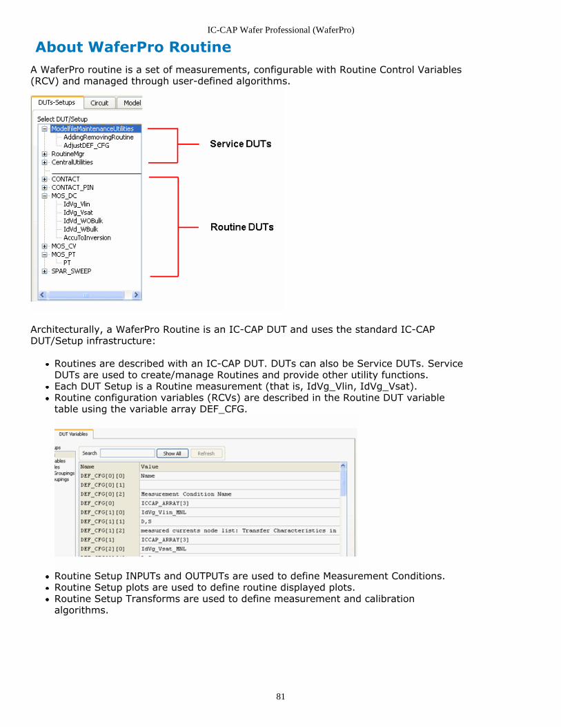
IC-CAP Wafer Professional (WaferPro)
81
About WaferPro RoutineA WaferPro routine is a set of measurements, configurable with Routine Control Variables(RCV) and managed through user-defined algorithms.
Architecturally, a WaferPro Routine is an IC-CAP DUT and uses the standard IC-CAPDUT/Setup infrastructure:
Routines are described with an IC-CAP DUT. DUTs can also be Service DUTs. ServiceDUTs are used to create/manage Routines and provide other utility functions.Each DUT Setup is a Routine measurement (that is, IdVg_Vlin, IdVg_Vsat).Routine configuration variables (RCVs) are described in the Routine DUT variabletable using the variable array DEF_CFG.
Routine Setup INPUTs and OUTPUTs are used to define Measurement Conditions.Routine Setup plots are used to define routine displayed plots.Routine Setup Transforms are used to define measurement and calibrationalgorithms.
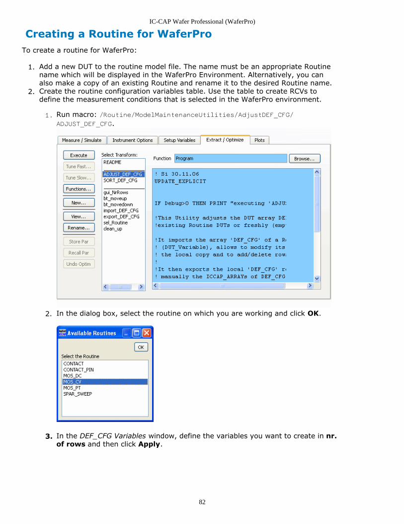
IC-CAP Wafer Professional (WaferPro)
82
Creating a Routine for WaferProTo create a routine for WaferPro:
Add a new DUT to the routine model file. The name must be an appropriate Routine1.name which will be displayed in the WaferPro Environment. Alternatively, you canalso make a copy of an existing Routine and rename it to the desired Routine name.Create the routine configuration variables table. Use the table to create RCVs to2.define the measurement conditions that is selected in the WaferPro environment.
Run macro: /Routine/ModelMaintenanceUtilities/AdjustDEF_CFG/1.
ADJUST_DEF_CFG.
In the dialog box, select the routine on which you are working and click OK.2.
In the DEF_CFG Variables window, define the variables you want to create in nr.3.of rows and then click Apply.
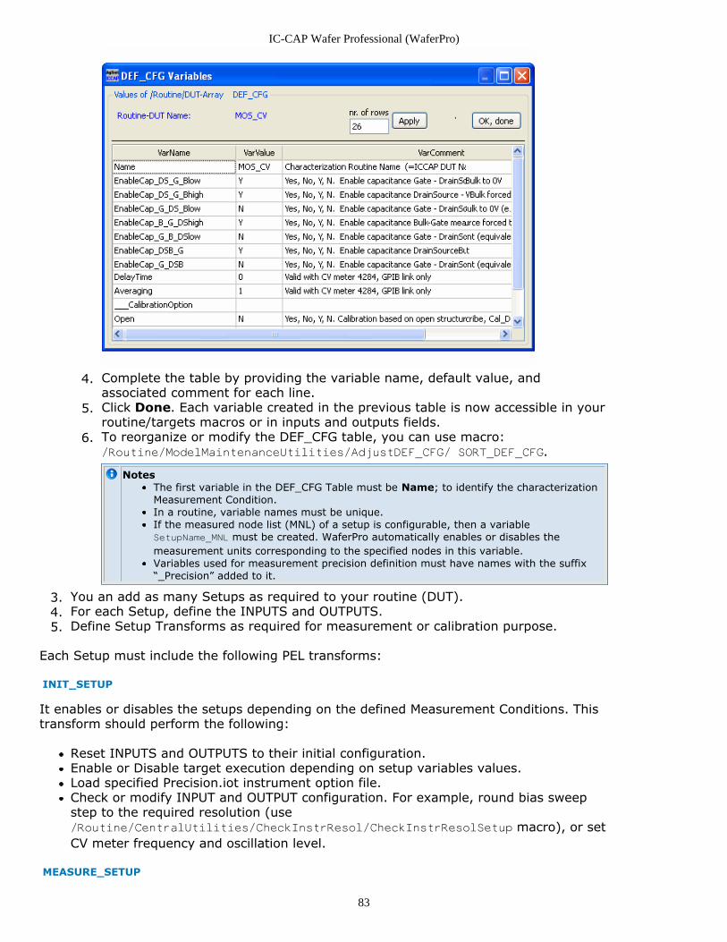
IC-CAP Wafer Professional (WaferPro)
83
Complete the table by providing the variable name, default value, and4.associated comment for each line.Click Done. Each variable created in the previous table is now accessible in your5.routine/targets macros or in inputs and outputs fields.To reorganize or modify the DEF_CFG table, you can use macro:6./Routine/ModelMaintenanceUtilities/AdjustDEF_CFG/ SORT_DEF_CFG.
NotesThe first variable in the DEF_CFG Table must be Name; to identify the characterizationMeasurement Condition.In a routine, variable names must be unique.If the measured node list (MNL) of a setup is configurable, then a variableSetupName_MNL must be created. WaferPro automatically enables or disables themeasurement units corresponding to the specified nodes in this variable.Variables used for measurement precision definition must have names with the suffix“_Precision” added to it.
You an add as many Setups as required to your routine (DUT).3.For each Setup, define the INPUTS and OUTPUTS.4.Define Setup Transforms as required for measurement or calibration purpose.5.
Each Setup must include the following PEL transforms:
INIT_SETUP
It enables or disables the setups depending on the defined Measurement Conditions. Thistransform should perform the following:
Reset INPUTS and OUTPUTS to their initial configuration.Enable or Disable target execution depending on setup variables values.Load specified Precision.iot instrument option file.Check or modify INPUT and OUTPUT configuration. For example, round bias sweepstep to the required resolution (use/Routine/CentralUtilities/CheckInstrResol/CheckInstrResolSetup macro), or setCV meter frequency and oscillation level.
MEASURE_SETUP
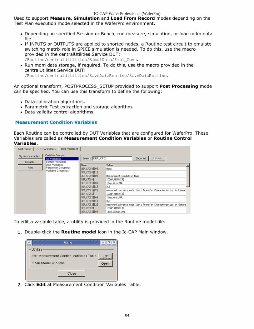
IC-CAP Wafer Professional (WaferPro)
84
Used to support Measure, Simulation and Load From Record modes depending on theTest Plan execution mode selected in the WaferPro environment.
Depending on specified Session or Bench, run measure, simulation, or load mdm datafile.If INPUTS or OUTPUTS are applied to shorted nodes, a Routine test circuit to emulateswitching matrix role in SPICE simulation is needed. To do this, use the macroprovided in the centralUtilities Service DUT:/Routine/centralUtilities/SimulData/Emul_Conn.Run mdm data storage, if required. To do this, use the macro provided in thecentralUtilities Service DUT:/Routine/centralUtilities/SaveDataRoutine/SaveDataRoutine.
An optional transform, POSTPROCESS_SETUP provided to support Post Processing modecan be specified. You can use this transform to define the following:
Data calibration algorithms.Parametric Test extraction and storage algorithm.Data validity control algorithms.
Measurement Condition Variables
Each Routine can be controlled by DUT Variables that are configured for WaferPro. TheseVariables are called as Measurement Condition Variables or Routine ControlVariables.
To edit a variable table, a utility is provided in the Routine model file:
Double-click the Routine model icon in the Ic-CAP Main window.1.
Click Edit at Measurement Condition Variables Table.2.
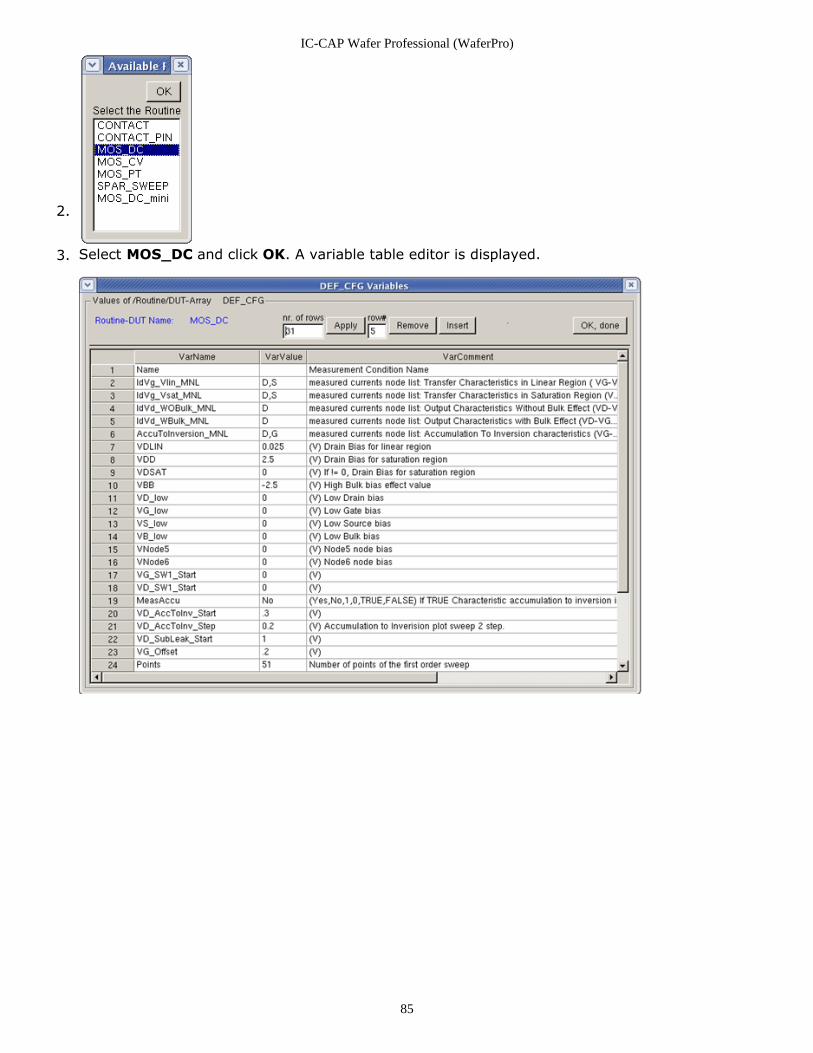
IC-CAP Wafer Professional (WaferPro)
85
2.
Select MOS_DC and click OK. A variable table editor is displayed.3.
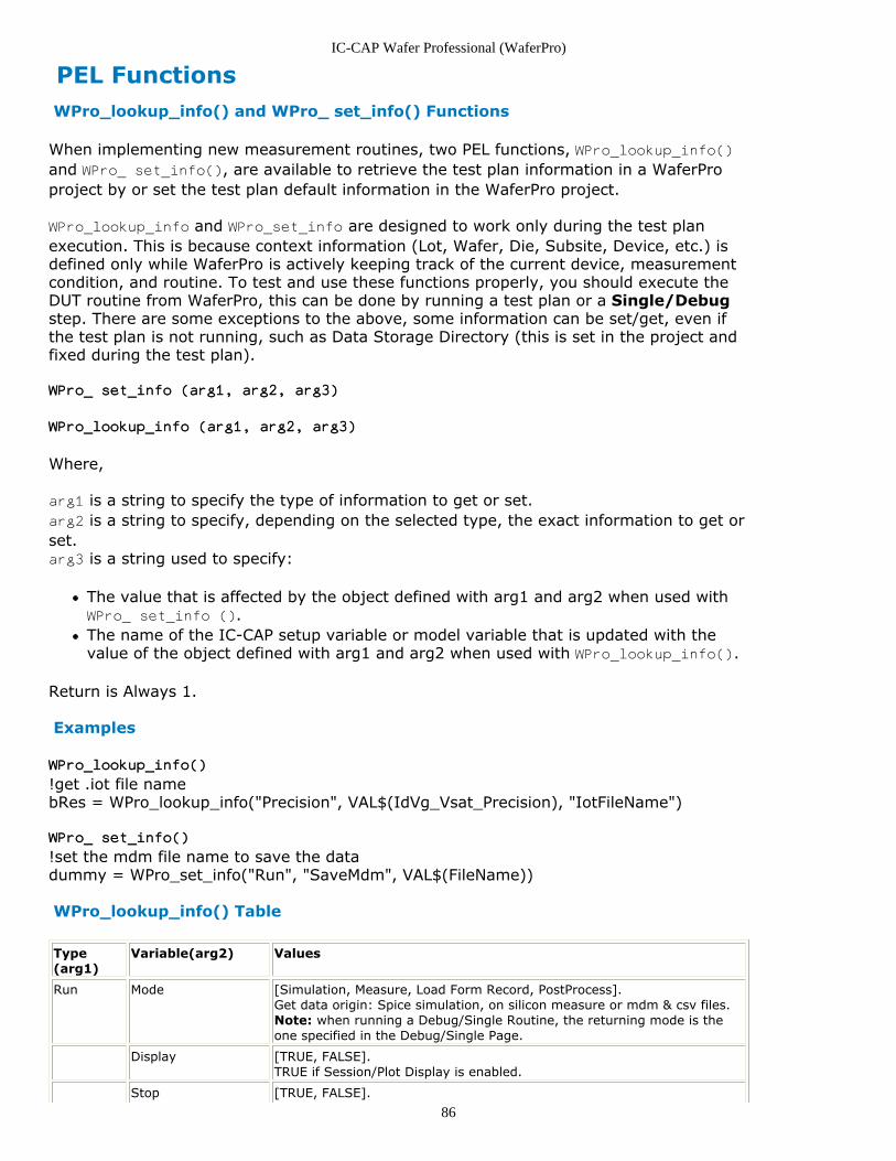
IC-CAP Wafer Professional (WaferPro)
86
PEL Functions WPro_lookup_info() and WPro_ set_info() Functions
When implementing new measurement routines, two PEL functions, WPro_lookup_info()and WPro_ set_info(), are available to retrieve the test plan information in a WaferProproject by or set the test plan default information in the WaferPro project.
WPro_lookup_info and WPro_set_info are designed to work only during the test planexecution. This is because context information (Lot, Wafer, Die, Subsite, Device, etc.) isdefined only while WaferPro is actively keeping track of the current device, measurementcondition, and routine. To test and use these functions properly, you should execute theDUT routine from WaferPro, this can be done by running a test plan or a Single/Debugstep. There are some exceptions to the above, some information can be set/get, even ifthe test plan is not running, such as Data Storage Directory (this is set in the project andfixed during the test plan).
WPro_ set_info (arg1, arg2, arg3)
WPro_lookup_info (arg1, arg2, arg3)
Where,
arg1 is a string to specify the type of information to get or set.arg2 is a string to specify, depending on the selected type, the exact information to get orset.arg3 is a string used to specify:
The value that is affected by the object defined with arg1 and arg2 when used withWPro_ set_info ().The name of the IC-CAP setup variable or model variable that is updated with thevalue of the object defined with arg1 and arg2 when used with WPro_lookup_info().
Return is Always 1.
Examples
WPro_lookup_info()
!get .iot file namebRes = WPro_lookup_info("Precision", VAL$(IdVg_Vsat_Precision), "IotFileName")
WPro_ set_info()
!set the mdm file name to save the datadummy = WPro_set_info("Run", "SaveMdm", VAL$(FileName))
WPro_lookup_info() Table
Type(arg1)
Variable(arg2) Values
Run Mode [Simulation, Measure, Load Form Record, PostProcess].Get data origin: Spice simulation, on silicon measure or mdm & csv files.Note: when running a Debug/Single Routine, the returning mode is theone specified in the Debug/Single Page.
Display [TRUE, FALSE].TRUE if Session/Plot Display is enabled.
Stop [TRUE, FALSE].
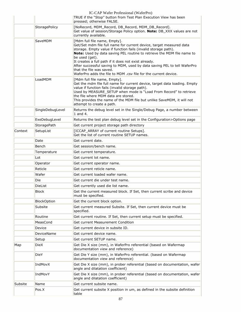
IC-CAP Wafer Professional (WaferPro)
87
TRUE if the “Stop” button from Test Plan Execution View has beenpressed; otherwise FALSE.
StoragePolicy [NoRecord, MDM_Record, DB_Record, MDM_DB_Record].Get value of session/Storage Policy option. Note: DB_XXX values are notcurrently available.
SaveMDM [Mdm full file name, Empty].Get/Set mdm file full name for current device, target measured datastorage. Empty value if function fails (invalid storage path).Note: Used by data saving PEL routine to retrieve the MDM file name tobe used (get).It creates a full path if it does not exist already.After successful saving to MDM, used by data saving PEL to tell WaferProthat the file was saved.WaferPro adds the file to MDM .csv file for the current device.
LoadMDM [Mdm full file name, Empty].Get the mdm file full name for current device, target data loading. Emptyvalue if function fails (invalid storage path).Used by MEASURE_SETUP when mode is “Load From Record” to retrievethe file where MDM data are stored.This provides the name of the MDM file but unlike SaveMDM, it will notattempt to create a path.
SingleDebugLevel Returns the debug level set in the Single/Debug Page, a number between1 and 4.
ExeDebugLevel Returns the test plan debug level set in the Configuration>Options page
StoragePath Get current project storage path directory
Context SetupList [ICCAP_ARRAY of current routine Setups].Get the list of current routine SETUP names.
Date Get current date.
Bench Get session/bench name.
Temperature Get current temperature.
Lot Get current lot name.
Operator Get current operator name.
Reticle Get current reticle name.
Wafer Get current loaded wafer name.
Die Get current die under test name.
DieList Get currently used die list name.
Block Get the current measured block. If Set, then current scribe and devicemust be specified.
BlockOption Get the current block option.
Subsite Get current measured Subsite. If Set, then current device must bespecified.
Routine Get current routine. If Set, then current setup must be specified.
MeasCond Get current Measurement Condition
Device Get current device in subsite ID.
DeviceName Get current device name.
Setup Get current SETUP name.
Map DieX Get Die X size (mm), in WaferPro referential (based on Wafermapdocumentation view and reference)
DieY Get Die Y size (mm), in WaferPro referential. (based on Wafermapdocumentation view and reference)
IndMovX Get Die X size (mm), in prober referential (based on documentation, waferangle and dilatation coefficient)
IndMovY Get Die X size (mm), in prober referential (based on documentation, waferangle and dilatation coefficient)
Subsite Name Get current subsite name.
Pos.X Get current subsite X position in um, as defined in the subsite definitiontable
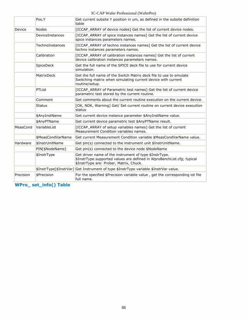
IC-CAP Wafer Professional (WaferPro)
88
Pos.Y Get current subsite Y position in um, as defined in the subsite definitiontable
Device Nodes [ICCAP_ARRAY of device nodes] Get the list of current device nodes.
DeviceInstances [ICCAP_ARRAY of spice instances names] Get the list of current devicespice instances parameters names.
TechnoInstances [ICCAP_ARRAY of techno instances names] Get the list of current devicetechno instances parameters names.
Calibration [ICCAP_ARRAY of calibration instances names] Get the list of currentdevice calibration instances parameters names.
SpiceDeck Get the full name of the SPICE deck file to use for current devicesimulation.
MatrixDeck Get the full name of the Switch Matrix deck file to use to emulateSwitching matrix when simulating current device with currentroutine/setup.
PTList [ICCAP_ARRAY of Parametric test names] Get the list of current deviceparametric test stored by the current routine.
Comment Get comments about the current routine execution on the current device.
Status [OK, NOK, Warning] Get/ Set current routine on current device executionstatus
$AnyInstName Get current device instance parameter $AnyInstName value.
$AnyPTName Get current device parametric test $AnyPTName result.
MeasCond VariableList [ICCAP_ARRAY of setup variables names] Get the list of currentMeasurement Condition variables names.
$MeasCondVarName Get current Measurement Condition variable $MeasCondVarName value.
Hardware $InstrUnitName Get pin(s) connected to the instrument unit $InstrUnitName.
PIN[$NodeName] Get pin(s) connected to the device node $NodeName
$InstrType Get driver name of the instrument of type $InstrType.$InstrType supported values are defined in WproBenchList.cfg; typical$InstrType are: Prober, Matrix, Chuck.
$InstrType[$InstrVar] Get Instrument of type $InstrType variable $InstrVar value.
Precision $Precision For the specified $Precision variable value , get the corresponding iot filefull name.
WPro_ set_info() Table
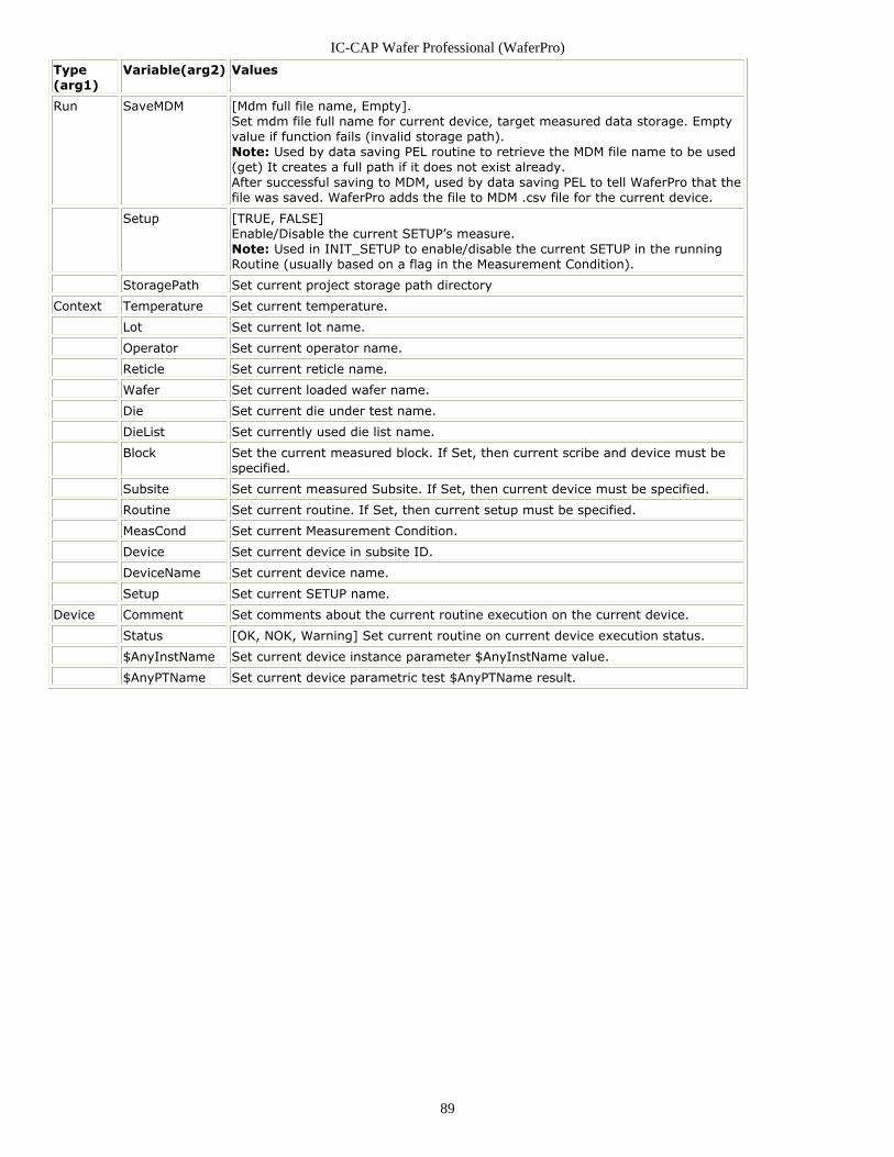
IC-CAP Wafer Professional (WaferPro)
89
Type(arg1)
Variable(arg2) Values
Run SaveMDM [Mdm full file name, Empty].Set mdm file full name for current device, target measured data storage. Emptyvalue if function fails (invalid storage path).Note: Used by data saving PEL routine to retrieve the MDM file name to be used(get) It creates a full path if it does not exist already.After successful saving to MDM, used by data saving PEL to tell WaferPro that thefile was saved. WaferPro adds the file to MDM .csv file for the current device.
Setup [TRUE, FALSE]Enable/Disable the current SETUP’s measure.Note: Used in INIT_SETUP to enable/disable the current SETUP in the runningRoutine (usually based on a flag in the Measurement Condition).
StoragePath Set current project storage path directory
Context Temperature Set current temperature.
Lot Set current lot name.
Operator Set current operator name.
Reticle Set current reticle name.
Wafer Set current loaded wafer name.
Die Set current die under test name.
DieList Set currently used die list name.
Block Set the current measured block. If Set, then current scribe and device must bespecified.
Subsite Set current measured Subsite. If Set, then current device must be specified.
Routine Set current routine. If Set, then current setup must be specified.
MeasCond Set current Measurement Condition.
Device Set current device in subsite ID.
DeviceName Set current device name.
Setup Set current SETUP name.
Device Comment Set comments about the current routine execution on the current device.
Status [OK, NOK, Warning] Set current routine on current device execution status.
$AnyInstName Set current device instance parameter $AnyInstName value.
$AnyPTName Set current device parametric test $AnyPTName result.
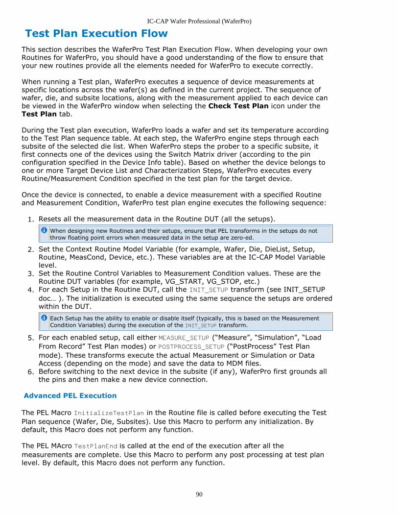
IC-CAP Wafer Professional (WaferPro)
90
Test Plan Execution FlowThis section describes the WaferPro Test Plan Execution Flow. When developing your ownRoutines for WaferPro, you should have a good understanding of the flow to ensure thatyour new routines provide all the elements needed for WaferPro to execute correctly.
When running a Test plan, WaferPro executes a sequence of device measurements atspecific locations across the wafer(s) as defined in the current project. The sequence ofwafer, die, and subsite locations, along with the measurement applied to each device canbe viewed in the WaferPro window when selecting the Check Test Plan icon under theTest Plan tab.
During the Test plan execution, WaferPro loads a wafer and set its temperature accordingto the Test Plan sequence table. At each step, the WaferPro engine steps through eachsubsite of the selected die list. When WaferPro steps the prober to a specific subsite, itfirst connects one of the devices using the Switch Matrix driver (according to the pinconfiguration specified in the Device Info table). Based on whether the device belongs toone or more Target Device List and Characterization Steps, WaferPro executes everyRoutine/Measurement Condition specified in the test plan for the target device.
Once the device is connected, to enable a device measurement with a specified Routineand Measurement Condition, WaferPro test plan engine executes the following sequence:
Resets all the measurement data in the Routine DUT (all the setups).1.
When designing new Routines and their setups, ensure that PEL transforms in the setups do notthrow floating point errors when measured data in the setup are zero-ed.
Set the Context Routine Model Variable (for example, Wafer, Die, DieList, Setup,2.Routine, MeasCond, Device, etc.). These variables are at the IC-CAP Model Variablelevel.Set the Routine Control Variables to Measurement Condition values. These are the3.Routine DUT variables (for example, VG_START, VG_STOP, etc.)For each Setup in the Routine DUT, call the INIT_SETUP transform (see INIT_SETUP4.doc… ). The initialization is executed using the same sequence the setups are orderedwithin the DUT.
Each Setup has the ability to enable or disable itself (typically, this is based on the MeasurementCondition Variables) during the execution of the INIT_SETUP transform.
For each enabled setup, call either MEASURE_SETUP (“Measure”, “Simulation”, “Load5.From Record” Test Plan modes) or POSTPROCESS_SETUP (“PostProcess” Test Planmode). These transforms execute the actual Measurement or Simulation or DataAccess (depending on the mode) and save the data to MDM files.Before switching to the next device in the subsite (if any), WaferPro first grounds all6.the pins and then make a new device connection.
Advanced PEL Execution
The PEL Macro InitializeTestPlan in the Routine file is called before executing the TestPlan sequence (Wafer, Die, Subsites). Use this Macro to perform any initialization. Bydefault, this Macro does not perform any function.
The PEL MAcro TestPlanEnd is called at the end of the execution after all themeasurements are complete. Use this Macro to perform any post processing at test planlevel. By default, this Macro does not perform any function.
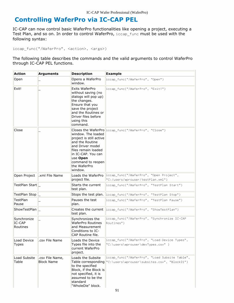
IC-CAP Wafer Professional (WaferPro)
91
Controlling WaferPro via IC-CAP PELIC-CAP can now control basic WaferPro functionalities like opening a project, executing aTest Plan, and so on. In order to control WaferPro, iccap_func must be used with thefollowing syntax:
iccap_func("/WaferPro", <action>, <args>)
The following table describes the commands and the valid arguments to control WaferProthrough IC-CAP PEL functions.
Action Arguments Description Example
Open _ Opens a WaferProwindow.
iccap_func("/WaferPro", "Open")
Exit! _ Exits WaferProwithout saving (nodialogs will pop up)the changes.Ensure that yousave the projectand the Routines orDriver files beforeusing thiscommand.
iccap_func("/WaferPro", "Exit!")
Close _ Closes the WaferProwindow. The loadedproject is still activeand the Routineand Driver modelfiles remain loadedin IC-CAP. You canuse Opencommand to reopenthe WaferProwindow.
iccap_func("/WaferPro", "Close")
Open Project .xml File Name Loads the WaferProproject file.
iccap_func("/WaferPro", "Open Project",
"C:/users/wprouser/testPlan.xml")
TestPlan Start _ Starts the currenttest plan.
iccap_func("/WaferPro", "TestPlan Start")
TestPlan Stop _ Stops the test plan. iccap_func("/WaferPro", "TestPlan Stop")
TestPlanPause
_ Pauses the testplan.
iccap_func("/WaferPro", "TestPlan Pause")
ShowTestPlan _ Creates the currenttest plan.
iccap_func("/WaferPro", "ShowTestPlan")
SynchronizeIC-CAPRoutines
_ Synchronizes theWaferPro Routinesand MeasurementConditions to IC-CAP Routine file.
iccap_func("/WaferPro", "Synchronize IC-CAP
Routines")
Load DeviceTypes
.csv File Name Loads the DeviceTypes file into thecurrent WaferProproject.
iccap_func("/WaferPro", "Load Device Types",
"C:\users\wprouser\devTypes.csv" )
Load SubsiteTable
.csv File Name,Block Name
Loads the SubsiteTable correspondingto the specifiedBlock, if the Block isnot specified, it isassumed to be thestandard"WholeDie" block.
iccap_func("/WaferPro", "Load Subsite Table",
"C:\users\wprouser\subsites.csv", "Block01")
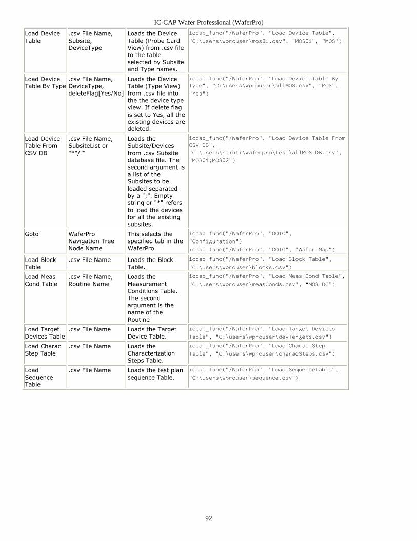
IC-CAP Wafer Professional (WaferPro)
92
Load DeviceTable
.csv File Name,Subsite,DeviceType
Loads the DeviceTable (Probe CardView) from .csv fileto the tableselected by Subsiteand Type names.
iccap_func("/WaferPro", "Load Device Table",
"C:\users\wprouser\mos01.csv", "MOS01", "MOS")
Load DeviceTable By Type
.csv File Name,DeviceType,deleteFlag[Yes/No]
Loads the DeviceTable (Type View)from .csv file intothe the device typeview. If delete flagis set to Yes, all theexisting devices aredeleted.
iccap_func("/WaferPro", "Load Device Table By
Type", "C:\users\wprouser\allMOS.csv", "MOS",
"Yes")
Load DeviceTable FromCSV DB
.csv File Name,SubsiteList or"*"/""
Loads theSubsite/Devicesfrom .csv Subsitedatabase file. Thesecond argument isa list of theSubsites to beloaded separatedby a ";". Emptystring or "*" refersto load the devicesfor all the existingsubsites.
iccap_func("/WaferPro", "Load Device Table From
CSV DB",
"C:\users\rtinti\waferpro\test\allMOS_DB.csv",
"MOS01;MOS02")
Goto WaferProNavigation TreeNode Name
This selects thespecified tab in theWaferPro.
iccap_func("/WaferPro", "GOTO",
"Configuration")
iccap_func("/WaferPro", "GOTO", "Wafer Map")
Load BlockTable
.csv File Name Loads the BlockTable.
iccap_func("/WaferPro", "Load Block Table",
"C:\users\wprouser\blocks.csv")
Load MeasCond Table
.csv File Name,Routine Name
Loads theMeasurementConditions Table.The secondargument is thename of theRoutine
iccap_func("/WaferPro", "Load Meas Cond Table",
"C:\users\wprouser\measConds.csv", “MOS_DC”)
Load TargetDevices Table
.csv File Name Loads the TargetDevice Table.
iccap_func("/WaferPro", "Load Target Devices
Table", "C:\users\wprouser\devTergets.csv")
Load CharacStep Table
.csv File Name Loads theCharacterizationSteps Table.
iccap_func("/WaferPro", "Load Charac Step
Table", "C:\users\wprouser\characSteps.csv")
LoadSequenceTable
.csv File Name Loads the test plansequence Table.
iccap_func("/WaferPro", "Load SequenceTable",
"C:\users\wprouser\sequence.csv")
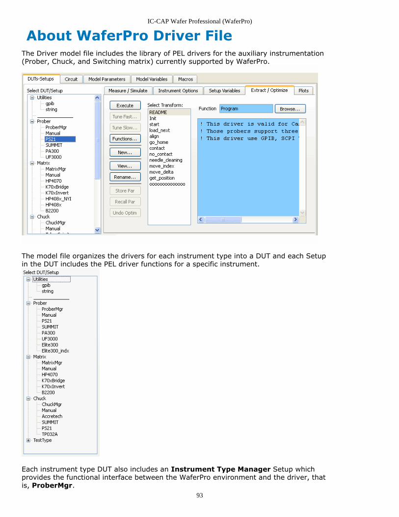
IC-CAP Wafer Professional (WaferPro)
93
About WaferPro Driver FileThe Driver model file includes the library of PEL drivers for the auxiliary instrumentation(Prober, Chuck, and Switching matrix) currently supported by WaferPro.
The model file organizes the drivers for each instrument type into a DUT and each Setupin the DUT includes the PEL driver functions for a specific instrument.
Each instrument type DUT also includes an Instrument Type Manager Setup whichprovides the functional interface between the WaferPro environment and the driver, thatis, ProberMgr.
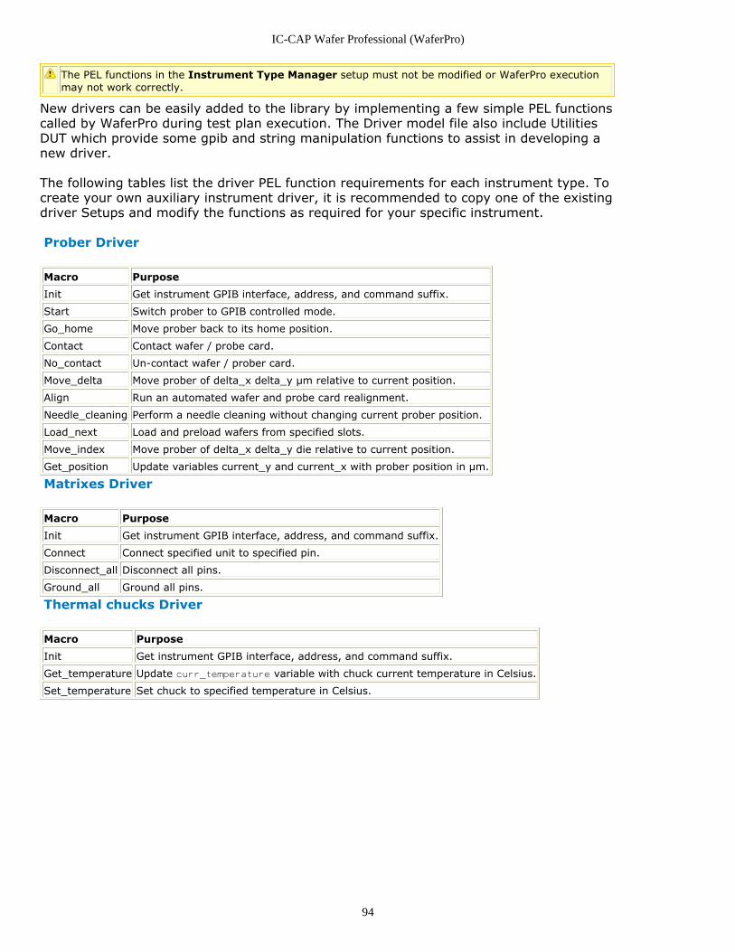
IC-CAP Wafer Professional (WaferPro)
94
The PEL functions in the Instrument Type Manager setup must not be modified or WaferPro executionmay not work correctly.
New drivers can be easily added to the library by implementing a few simple PEL functionscalled by WaferPro during test plan execution. The Driver model file also include UtilitiesDUT which provide some gpib and string manipulation functions to assist in developing anew driver.
The following tables list the driver PEL function requirements for each instrument type. Tocreate your own auxiliary instrument driver, it is recommended to copy one of the existingdriver Setups and modify the functions as required for your specific instrument.
Prober Driver
Macro Purpose
Init Get instrument GPIB interface, address, and command suffix.
Start Switch prober to GPIB controlled mode.
Go_home Move prober back to its home position.
Contact Contact wafer / probe card.
No_contact Un-contact wafer / prober card.
Move_delta Move prober of delta_x delta_y µm relative to current position.
Align Run an automated wafer and probe card realignment.
Needle_cleaning Perform a needle cleaning without changing current prober position.
Load_next Load and preload wafers from specified slots.
Move_index Move prober of delta_x delta_y die relative to current position.
Get_position Update variables current_y and current_x with prober position in µm.
Matrixes Driver
Macro Purpose
Init Get instrument GPIB interface, address, and command suffix.
Connect Connect specified unit to specified pin.
Disconnect_all Disconnect all pins.
Ground_all Ground all pins.
Thermal chucks Driver
Macro Purpose
Init Get instrument GPIB interface, address, and command suffix.
Get_temperature Update curr_temperature variable with chuck current temperature in Celsius.
Set_temperature Set chuck to specified temperature in Celsius.
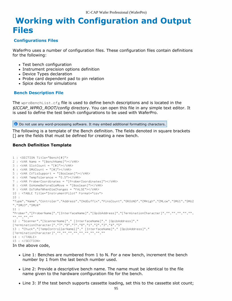
IC-CAP Wafer Professional (WaferPro)
95
Working with Configuration and OutputFiles Configurations Files
WaferPro uses a number of configuration files. These configuration files contain definitionsfor the following:
Test bench configurationInstrument precision options definitionDevice Types declarationProbe card dependent pad to pin relationSpice decks for simulations
Bench Description File
The wproBenchList.cfg file is used to define bench descriptions and is located in the$ICCAP_WPRO_ROOT/config directory. You can open this file in any simple text editor. Itis used to define the test bench configurations to be used with WaferPro.
Do not use any word-processing software. It may embed additional formatting characters.
The following is a template of the Bench definition. The fields denoted in square brackets[] are the fields that must be defined for creating a new bench.
Bench Definition Template
1 : <SECTION Title="Bench[#]">
2 : <VAR Name = "[BenchName]"></VAR>
3 : <VAR SlotCount = "[#]"></VAR>
4 : <VAR SMUCount = "[#]"></VAR>
5 : <VAR CVTisSupport = "[Boolean]"></VAR>
6 : <VAR TempTolerance = "0.5"></VAR>
7 : <VAR ProberCoordinates = "[ProberCoordinates]"></VAR>
8 : <VAR GoHomeBeforeDieMove = "[Boolean]"></VAR>
9 : <VAR GoToRefWhenDieChanges = "FALSE"></VAR>
10 : <TABLE Title="InstrumentPilot" Format="csv">
10 :
"Type","Name","Controler","Address","CmdSuffix","PinsCount","GROUND","CMHigh","CMLow","SMU1","SMU2
","SMU3","SMU4"
11 :
"Prober","[ProberName]","[InterfaceName]","[GpibAddress]","[TerminationCharacter]","","","","","",
"","","",""
12 : "Scanner","[ScannerName]"," [InterfaceName]"," [GpibAddress]","
[TerminationCharacter]","7","9","7","8","1","2","3","4","5"
13 : "Chuck","[TempControllerNamel]"," [InterfaceName]"," [GpibAddress]","
[TerminationCharacter]","","","","","","","","",""
14 : </TABLE>
15 : </SECTION>
In the above code,
Line 1: Benches are numbered from 1 to N. For a new bench, increment the benchnumber by 1 from the last bench number used.
Line 2: Provide a descriptive bench name. The name must be identical to the filename given to the hardware configuration file for the bench.
Line 3: If the test bench supports cassette loading, set this to the cassette slot count;
IC-CAP Wafer Professional (WaferPro)
96
else set it to 1.
Line 4: Set # to the number of SMU’s your parametric analyzer is configured for.
Line 5: Set to TRUE if the CV meter can be driven through the TIS interface (407x/8xsystems).
Line 6: Set the temperature tolerance value in degree. Usually, it is same as thevalue set in the prober.
Line 7: Set the X-Y coordinate direction mapping, that is, X-Right, Y-Up.
Line 8: Set to TRUE, if prober returns to HOME position before every move; else setto FALSE.
Line 9: Set to TRUE, if prober moves to Reference position of next die from the lastposition of the current die; else set to FALSE. In most cases, set this to False. Forsome probers, it may move to the Reference position of dies automatically, whenchanging dies, in which case this field should be set to True.
Line 10-12: The instrument pilot table is used to define configuration of contextcontrol instruments (prober, chuck, switching matrix). For each table column, thecorresponding instrument value is defined.
Type: Describes the instrument family. In WaferPro Driver model file, itcorresponds to the instrument driver DUT.Name: Instrument driver name.Controller: If exists, name of the computer GPIB controller.Address: If exists, Instrument GPIB address.CmdSuffix: GPIB command terminator character (that is, \r or \n).
The fields after CmdSuffix are variable in number and are applicable to the switchingmatrix only. They are used to define the measurement instruments units to switchingmatrix row connections.
Instrument Precision Files
The Instrument Precision files used with WaferPro are standard IC-CAP instrument optionfiles (.iot) that are used to define a desired characterization precision level for thesupported DC measurement instruments and to define any other desired instrumentoptions. These files are located in the $ICCAP_WPRO_ROOT/config directory.
It is recommended to use IC-CAP to create your Instrument Precision Files. Do not use any word-processing software to manually edit the file as tt may embed additional formatting characters.
The example below illustrates an Instrument Precision File created for the bench thatcontains an HP4156 Semiconductor Parametric Analyzer and an Agilent E4980 PrecisionLCR Meter. The integration time (Integ Time) for the HP4156 is set to “S” for ShortIntegration (fast measurement, but less accuracy). In the following example, note the useof variables for some of the instrument options for the Agilent E4980. These variables aredeclared in the PEL function /Routine/RoutineMgr/MeasureRoutine/InitRoutine which is atransform included in the WaferPro Routine model file, and then exposed to the WaferProenvironment by adding Routine Control Variables (RCVs) to a specific measurementroutine (See the RCV’s defined in the DUT Variable table of the MOS_DC routine).
Example
data
IC-CAP Wafer Professional (WaferPro)
97
{
TABLE "AgilentE4980.7.17"
{
View par_var_table 1 "V530 C18 C15"
element 0 "Hold Time" " HOLD "
element 0 "Delay Time" " DELAY "
element 0 "Meas Freq" " CV_FM"
element 0 "Integ Time" "S"
element 0 "Osc Level" " CV_SIG"
element 0 "Osc Mode [V,I]" "V"
element 0 "Averaging [1-256|1-256]" " AVERAGE "
element 0 "Cable Length" "1"
element 0 "Delay for Timeouts" " 0.000 "
element 0 "Init Command" "CORR:OPEN:STAT OFF;:CORR:LENG 1"
}
TABLE "HP4156.4000.24"
{
View par_var_table 0 "V530 C18 C15"
element 0 "Use User Sweep" "No"
element 0 "Hold Time" " HOLD "
element 0 "Delay Time" " DELAY "
element 0 "Integ Time" "S"
element 0 "Power Compliance" " 0.000 "
element 0 "Pulse Unit" ""
element 0 "Pulse Base" " 0.000 "
element 0 "Pulse Width" " 1.000m"
element 0 "Pulse Period" " 10.00m"
element 0 "Delay for timeouts" " 1000.0 "
element 0 "Init Command" ""
}
}
Making an Instrument Options (.iot) File
WaferPro automatically loads an Instrument Options (iot) file from$ICCAP_WPRO_ROOT/instr (=$ICCAP_ROOT/waferpro/instr as default) at eachmeasurement (Setup) in the Routine(=DUT) based on the precision setting inMeasurement Condition table of the Test Plan. Therefore, Instrument Options (iot) files,for example, Short.iot, Medium.iot and Long.iot, need to include all the instrumentsused in the Test Plan. (Furthermore, you must include all the instruments supported byyour measurement environment for general use in WaferPro.)
To make the iot files, use the WPro_Instr_Cfg.mdl and AllInstr.hdw files available in theinstr directory.
Follow the process below to use these files:
Prepare a $Bench.hdw, where $Bench is the name of your test bench. It is assumed thatthe hdw file is created with your actual measurement system connected, that is, by“rebuilding” in the Hardware Setup window.
Edit AllInstr.hdw file and add the new instruments in the file. (copy from1.$Bench.hdw, which must be created earlier.)Load AllInstr.hdw file in the Hardware Setup window.2.Load WPro_Instr_Cfg.mdl file.3.Load one of the iot file.4.Open the instrument options table in the model window and edit the option values for5.the newly added instruments.Add one Input component in the Setup to show the instrument options table.6.Save the modified iot file.7.Save the WPro_Instr_Cfg.mdl file.8.
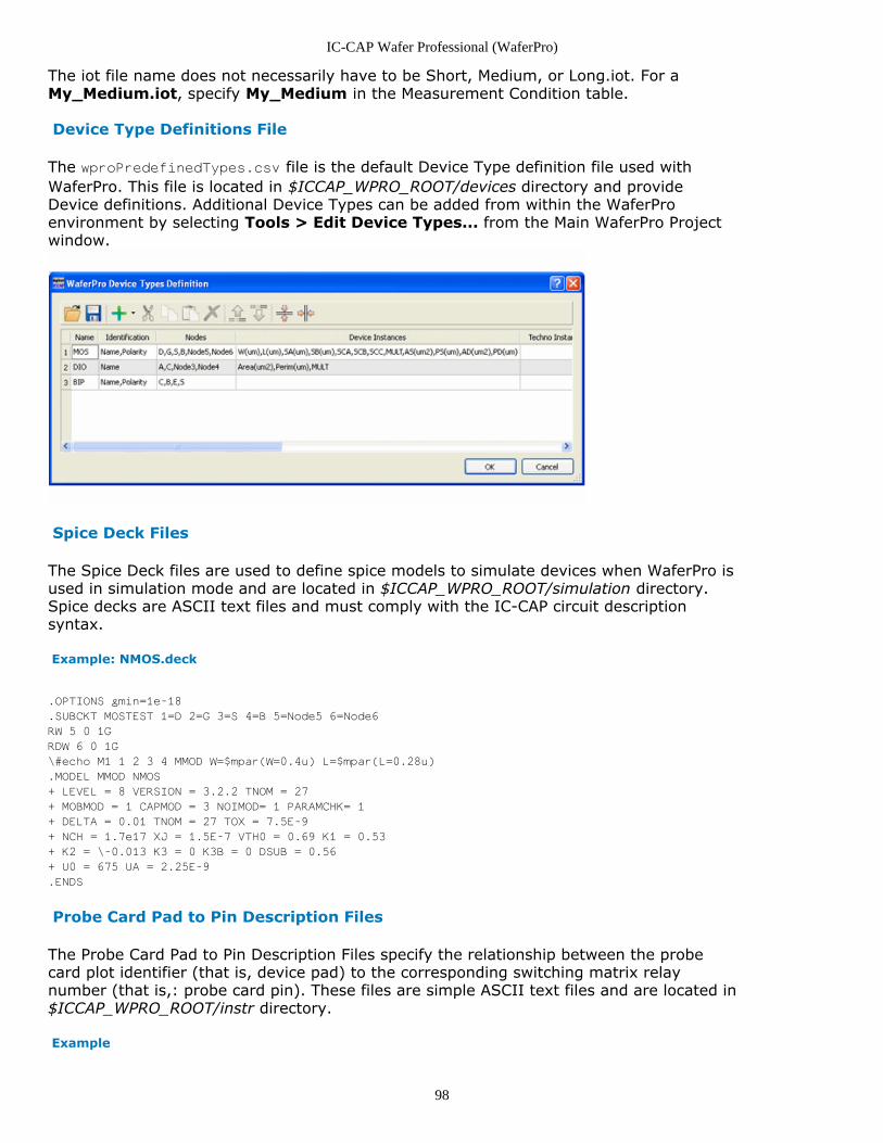
IC-CAP Wafer Professional (WaferPro)
98
The iot file name does not necessarily have to be Short, Medium, or Long.iot. For aMy_Medium.iot, specify My_Medium in the Measurement Condition table.
Device Type Definitions File
The wproPredefinedTypes.csv file is the default Device Type definition file used withWaferPro. This file is located in $ICCAP_WPRO_ROOT/devices directory and provideDevice definitions. Additional Device Types can be added from within the WaferProenvironment by selecting Tools > Edit Device Types... from the Main WaferPro Projectwindow.
Spice Deck Files
The Spice Deck files are used to define spice models to simulate devices when WaferPro isused in simulation mode and are located in $ICCAP_WPRO_ROOT/simulation directory.Spice decks are ASCII text files and must comply with the IC-CAP circuit descriptionsyntax.
Example: NMOS.deck
.OPTIONS gmin=1e-18
.SUBCKT MOSTEST 1=D 2=G 3=S 4=B 5=Node5 6=Node6
RW 5 0 1G
RDW 6 0 1G
\#echo M1 1 2 3 4 MMOD W=$mpar(W=0.4u) L=$mpar(L=0.28u)
.MODEL MMOD NMOS
+ LEVEL = 8 VERSION = 3.2.2 TNOM = 27
+ MOBMOD = 1 CAPMOD = 3 NOIMOD= 1 PARAMCHK= 1
+ DELTA = 0.01 TNOM = 27 TOX = 7.5E-9
+ NCH = 1.7e17 XJ = 1.5E-7 VTH0 = 0.69 K1 = 0.53
+ K2 = \-0.013 K3 = 0 K3B = 0 DSUB = 0.56
+ U0 = 675 UA = 2.25E-9
.ENDS
Probe Card Pad to Pin Description Files
The Probe Card Pad to Pin Description Files specify the relationship between the probecard plot identifier (that is, device pad) to the corresponding switching matrix relaynumber (that is,: probe card pin). These files are simple ASCII text files and are located in$ICCAP_WPRO_ROOT/instr directory.
Example
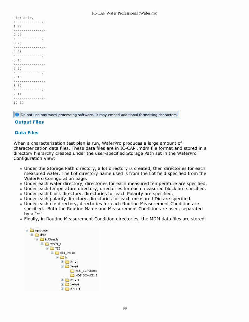
IC-CAP Wafer Professional (WaferPro)
99
Plot Relay
\-------------\-
1 22
\-------------\-
2 26
\-------------\-
3 20
\-------------\-
4 28
\-------------\-
5 18
\-------------\-
6 30
\-------------\-
7 16
\-------------\-
8 32
\-------------\-
9 14
\-------------\-
10 34
Do not use any word-processing software. It may embed additional formatting characters.
Output Files
Data Files
When a characterization test plan is run, WaferPro produces a large amount ofcharacterization data files. These data files are in IC-CAP .mdm file format and stored in adirectory hierarchy created under the user-specified Storage Path set in the WaferProConfiguration View:
Under the Storage Path directory, a lot directory is created, then directories for eachmeasured wafer. The Lot directory name used is from the Lot field specified from theWaferPro Configuration page.Under each wafer directory, directories for each measured temperature are specified.Under each temperature directory, directories for each measured block are specified.Under each block directory, directories for each Polarity are specified.Under each polarity directory, directories for each measured Die are specified.Under each die directory, directories for each Routine Measurement Condition arespecified.. Both the Routine Name and Measurement Condition are used, separatedby a “~”.Finally, in Routine Measurement Condition directories, the MDM data files are stored.
IC-CAP Wafer Professional (WaferPro)
100
The naming convention used for the MDM files uses the following elements projectseparated with a tilde “~” between each:
<SubsiteName>~<DeviceName>~<DeviceID>~<RoutineSetupName>.mdm
Where,
SubsiteName is the subsite name specified in the Subsites table.
DeviceName is the device name defined in the Device Info device definition table.
Device ID is the row number of the device listed in the Device Definition table.
RoutineSetupName is the name of the Routine measurement setup used to create thedata.
If a “/” is used in the Device Name, it is replaced by “~” in the MDM file name.
Example
MOS01~N10~0.5~3~IdVd_WOBulk.mdm
Characterization Report File
A Characterization Report file is generated when the test plan is executed. It is stored inthe Lot sub-directory created to store the measured data. The filename given to theCharacterization Report is WPROTestPlanRep~<BenchName>.txt.
Where, BenchName is the name of the bench selected for the measurement.
Parametric Test Results Files
Parametric test results are stored in a .csv file for each routine/setup executed in the testplan. They are stored in the Lot sub-directory created to store the measured data. Thisfile contains Test Plan Project ID information, the Routine name, the MeasurementCondition name and description, and finally the Parametric Test Results the measured oneach wafer/block/die/temperature/subsite/device selected for characterization as well asthe execution status and any warnings or error messages.
The naming convention for these files is:
<Bench>~<Mode>~<DeviceType>~<Routine>~<MeasCond>.csv
Where,
Bench is the name of the Test Bench selected for the measurement.
Mode is the test plan execution mode.
DeviceType is the type of device being tested (for example, MOS, BIP etc).
Routine is the name of the Routine used for the measurement.
MeasCond is the selected Measurement Condition used.
Example
OffLine~Simu~MOS~MOS_DC~VDD18.csv
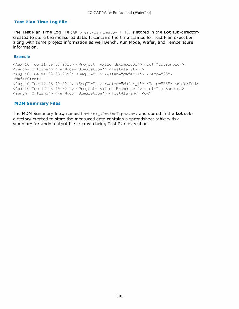
IC-CAP Wafer Professional (WaferPro)
101
Test Plan Time Log File
The Test Plan Time Log File (WProTestPlanTimeLog.txt), is stored in the Lot sub-directorycreated to store the measured data. It contains the time stamps for Test Plan executionalong with some project information as well Bench, Run Mode, Wafer, and Temperatureinformation.
Example
<Aug 10 Tue 11:59:53 2010> <Project="AgilentExample01"> <Lot="LotSample">
<Bench="OffLine"> <runMode="Simulation"> <TestPlanStart>
<Aug 10 Tue 11:59:53 2010> <SeqID="1"> <Wafer="Wafer_1"> <Temp="25">
<WaferStart>
<Aug 10 Tue 12:03:49 2010> <SeqID="1"> <Wafer="Wafer_1"> <Temp="25"> <WaferEnd>
<Aug 10 Tue 12:03:49 2010> <Project="AgilentExample01"> <Lot="LotSample">
<Bench="OffLine"> <runMode="Simulation"> <TestPlanEnd> <OK>
MDM Summary Files
The MDM Summary files, named MdmList_<DeviceType>.csv and stored in the Lot sub-directory created to store the measured data contains a spreadsheet table with asummary for .mdm output file created during Test Plan execution.
IC-CAP Wafer Professional (WaferPro)
102
Using WaferPro with Parametric TestSystem and Auto ProbersIC-CAP Wafer Professional (WaferPro) is a measurement application integrated with theIC-CAP platform. As WaferPro is based on the IC-CAP Modeling Software, it provides anefficient control of analyzers, probers, and parametric test systems. This topic providesinformation on how you can use IC-CAP Wafer Professional (WaferPro) with the followingparametric test systems and auto probers:
Agilent's 407x and 408x Semiconductor Parametric Test SystemsAccretech UF200 and UF300/UF3000 Wafer Probing MachinesTokyo Electron P-8 and P-12 Auto Probers
About Agilent 407x and 408x Semiconductor Parametric Test SystemsAgilent has two families of production parametric testers. The 407x Series is the standardfor wafer fabrication facilities world-wide. The 408x Series is designed to solve parametrictest challenges posed by advanced processes with lithography of 45 nanometers or below.
About Accretech UF200 and UF300/UF3000 Wafer Probing Machines
Accretech's wafer probing machines perform electrical tests of each chip on a wafer toensure the quality of semiconductor devices. For more information on Accretech WaferProbing Machines, refer to http://www.accretech.jp/english/semicon/product/c/wafer_pm .
About Tokyo Electron P-8/P-12 Wafer Prober SeriesThe P-8XL prober series provide the optimum probing environment for 100, 150 and200mm wafer testing. Based on TEL's On-Axis Alignment System, the P-8XL seriessatisfies the needs of multi-DUT memory devices and high-speed multi-pin logic devices.The P-12XL prober series retains TEL's acclaimed On-Axis-Alignment feature of previousmodels and eliminates probe pin placement errors under both high and low temperatureconditions. For more information on Tokyo Electron P-8/P-12 Auto Probers, refer tohttp://www.tel.com/eng/product/wps/buwps.htm .
Test procedure
The process to use WaferPro with Parametric Test System and Auto Probers is covered inthe following topics:
Setting Up the Parametric Test System and Auto ProbersBefore You Launch IC-CAPTest Bench and Instrument SettingsAn Example Parametric Test System ProjectSending Commands to Wafer Probers
Setting Up the Parametric Test System and Auto Probers
Before you begin using WaferPro with Parametric Test System and Auto Probers, ensurethat following hardware or software requirements are met.
Hardware Requirements
The following hardware must be installed on the parametric test system controllerworkstation:
TAMS GP-IB Interface Card
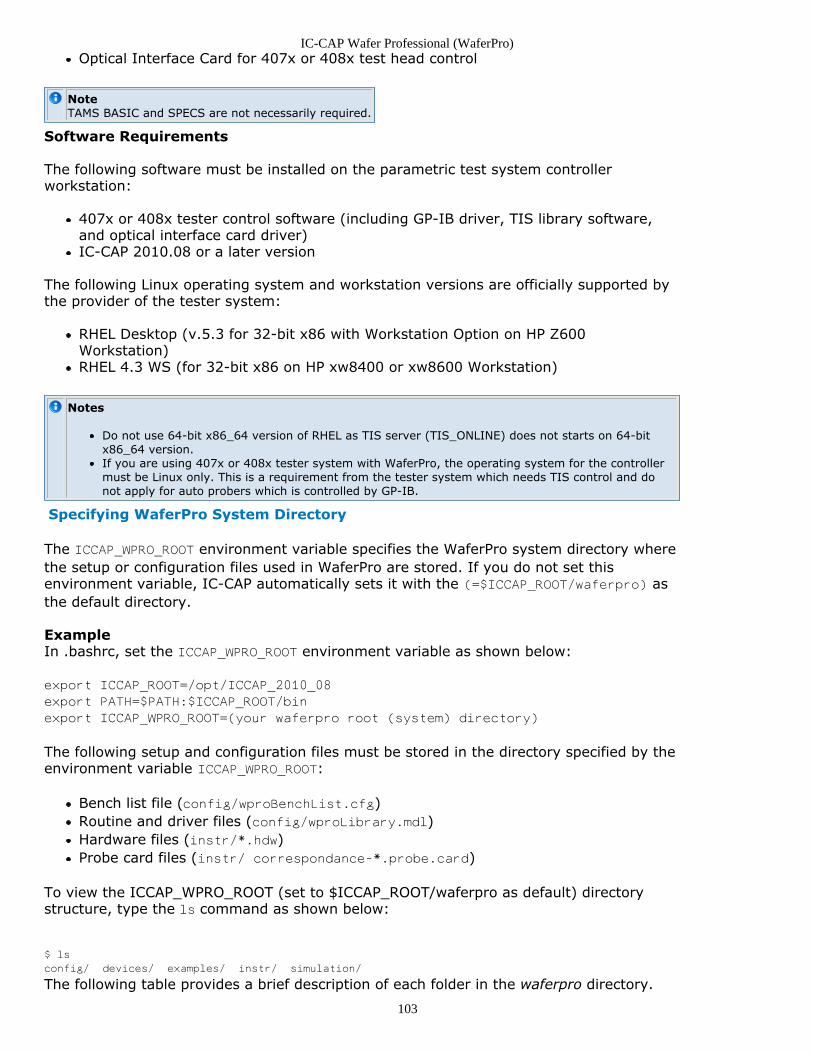
IC-CAP Wafer Professional (WaferPro)
103
Optical Interface Card for 407x or 408x test head control
NoteTAMS BASIC and SPECS are not necessarily required.
Software Requirements
The following software must be installed on the parametric test system controllerworkstation:
407x or 408x tester control software (including GP-IB driver, TIS library software,and optical interface card driver)IC-CAP 2010.08 or a later version
The following Linux operating system and workstation versions are officially supported bythe provider of the tester system:
RHEL Desktop (v.5.3 for 32-bit x86 with Workstation Option on HP Z600Workstation)RHEL 4.3 WS (for 32-bit x86 on HP xw8400 or xw8600 Workstation)
Notes
Do not use 64-bit x86_64 version of RHEL as TIS server (TIS_ONLINE) does not starts on 64-bitx86_64 version.If you are using 407x or 408x tester system with WaferPro, the operating system for the controllermust be Linux only. This is a requirement from the tester system which needs TIS control and donot apply for auto probers which is controlled by GP-IB.
Specifying WaferPro System Directory
The ICCAP_WPRO_ROOT environment variable specifies the WaferPro system directory wherethe setup or configuration files used in WaferPro are stored. If you do not set thisenvironment variable, IC-CAP automatically sets it with the (=$ICCAP_ROOT/waferpro) asthe default directory.
ExampleIn .bashrc, set the ICCAP_WPRO_ROOT environment variable as shown below:
export ICCAP_ROOT=/opt/ICCAP_2010_08
export PATH=$PATH:$ICCAP_ROOT/bin
export ICCAP_WPRO_ROOT=(your waferpro root (system) directory)
The following setup and configuration files must be stored in the directory specified by theenvironment variable ICCAP_WPRO_ROOT:
Bench list file (config/wproBenchList.cfg)Routine and driver files (config/wproLibrary.mdl)Hardware files (instr/*.hdw)Probe card files (instr/ correspondance-*.probe.card)
To view the ICCAP_WPRO_ROOT (set to $ICCAP_ROOT/waferpro as default) directorystructure, type the ls command as shown below:
$ ls
config/ devices/ examples/ instr/ simulation/
The following table provides a brief description of each folder in the waferpro directory.
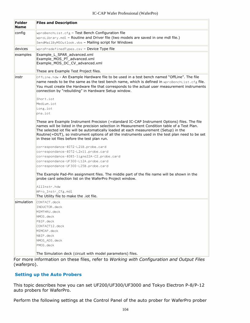
IC-CAP Wafer Professional (WaferPro)
104
FolderName
Files and Description
config wproBenchList.cfg – Test Bench Configuration filewproLibrary.mdl – Routine and Driver file (two models are saved in one mdl file.)SendMailByMSOutlook.vbs – Mailing script for Windows
devices wproPredefinedTypes.csv – Device Type file
examples Example_L_SPAR_advanced.xmlExample_MOS_PT_advanced.xmlExample_MOS_DC_CV_advanced.xml
These are Example Test Project files.
instr OffLine.hdw - An Example Hardware file to be used in a test bench named “OffLine”. The filename needs to be the same as the test bench name, which is defined in wproBenchList.cfg file.You must create the Hardware file that corresponds to the actual user measurement instrumentsconnection by “rebuilding” in Hardware Setup window.
Short.iot
Medium.iot
Long.iot
pna.iot
These are Example Instrument Precision (=standard IC-CAP Instrument Options) files. The filenames will be listed in the precision selection in Measurement Condition table of a Test Plan.The selected iot file will be automatically loaded at each measurement (Setup) in theRoutine(=DUT), so instrument options of all the instruments used in the test plan need to be setin these iot files before the test plan run.
correspondance-4072-L21B.probe.card
correspondance-4072-L2x11.probe.card
correspondance-4085-ligne22A-C2.probe.card
correspondance-UF300-L12A.probe.card
correspondance-UF300-L25B.probe.card
The Example Pad-Pin assignment files. The middle part of the file name will be shown in theprobe card selection list on the WaferPro Project window.
AllInstr.hdw
WPro_Instr_Cfg.mdl
The Utility file to make the .iot file.
simulation CONTACT.deck
INDUCTOR.deck
MIMTHRU.deck
NMOS.deck
PBIP.deck
CONTACT12.deck
MIMCAP.deck
NBIP.deck
NMOS_ADS.deck
PMOS.deck
The Simulation deck (circuit with model parameters) files.
For more information on these files, refer to Working with Configuration and Output Files(waferpro).
Setting up the Auto Probers
This topic describes how you can set UF200/UF300/UF3000 and Tokyo Electron P-8/P-12auto probers for WaferPro.
Perform the following settings at the Control Panel of the auto prober for WaferPro prober
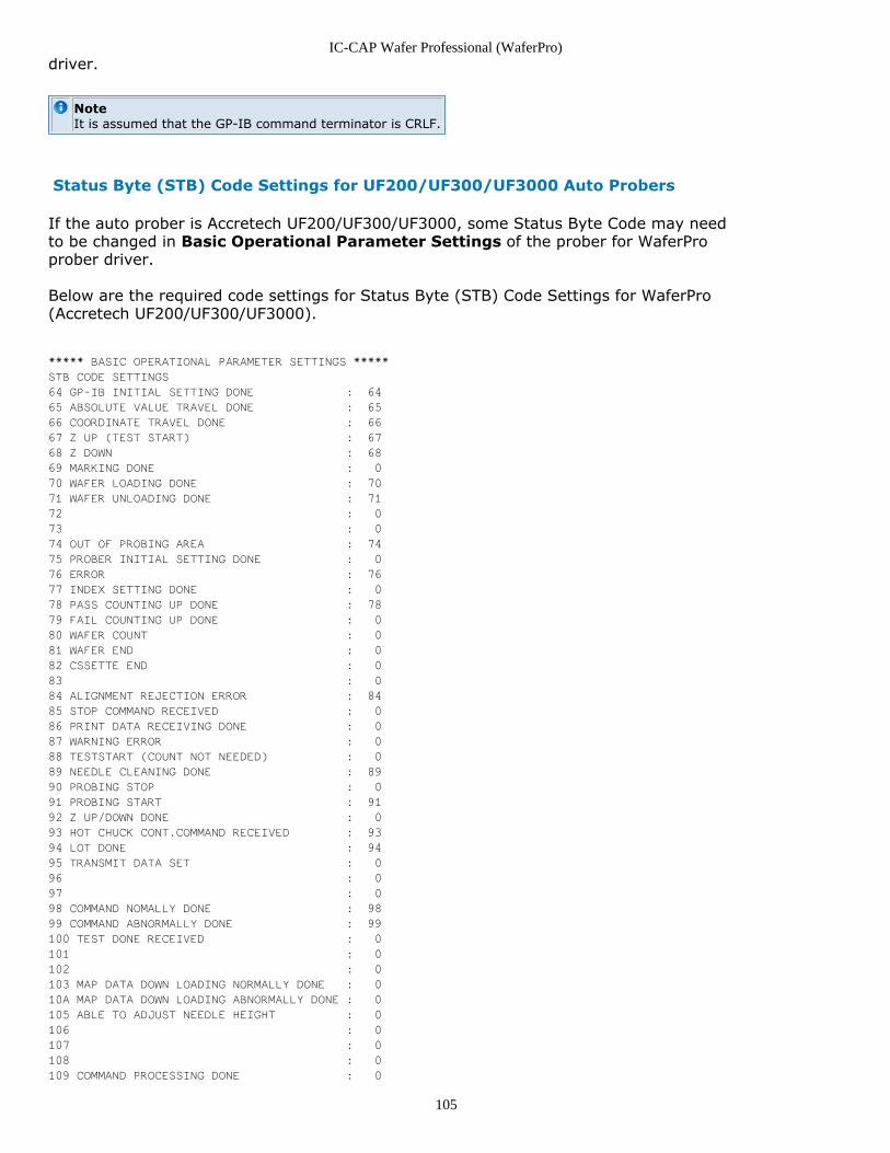
IC-CAP Wafer Professional (WaferPro)
105
driver.
NoteIt is assumed that the GP-IB command terminator is CRLF.
Status Byte (STB) Code Settings for UF200/UF300/UF3000 Auto Probers
If the auto prober is Accretech UF200/UF300/UF3000, some Status Byte Code may needto be changed in Basic Operational Parameter Settings of the prober for WaferProprober driver.
Below are the required code settings for Status Byte (STB) Code Settings for WaferPro(Accretech UF200/UF300/UF3000).
***** BASIC OPERATIONAL PARAMETER SETTINGS *****
STB CODE SETTINGS
64 GP-IB INITIAL SETTING DONE : 64
65 ABSOLUTE VALUE TRAVEL DONE : 65
66 COORDINATE TRAVEL DONE : 66
67 Z UP (TEST START) : 67
68 Z DOWN : 68
69 MARKING DONE : 0
70 WAFER LOADING DONE : 70
71 WAFER UNLOADING DONE : 71
72 : 0
73 : 0
74 OUT OF PROBING AREA : 74
75 PROBER INITIAL SETTING DONE : 0
76 ERROR : 76
77 INDEX SETTING DONE : 0
78 PASS COUNTING UP DONE : 78
79 FAIL COUNTING UP DONE : 0
80 WAFER COUNT : 0
81 WAFER END : 0
82 CSSETTE END : 0
83 : 0
84 ALIGNMENT REJECTION ERROR : 84
85 STOP COMMAND RECEIVED : 0
86 PRINT DATA RECEIVING DONE : 0
87 WARNING ERROR : 0
88 TESTSTART (COUNT NOT NEEDED) : 0
89 NEEDLE CLEANING DONE : 89
90 PROBING STOP : 0
91 PROBING START : 91
92 Z UP/DOWN DONE : 0
93 HOT CHUCK CONT.COMMAND RECEIVED : 93
94 LOT DONE : 94
95 TRANSMIT DATA SET : 0
96 : 0
97 : 0
98 COMMAND NOMALLY DONE : 98
99 COMMAND ABNORMALLY DONE : 99
100 TEST DONE RECEIVED : 0
101 : 0
102 : 0
103 MAP DATA DOWN LOADING NORMALLY DONE : 0
10A MAP DATA DOWN LOADING ABNORMALLY DONE : 0
105 ABLE TO ADJUST NEEDLE HEIGHT : 0
106 : 0
107 : 0
108 : 0
109 COMMAND PROCESSING DONE : 0
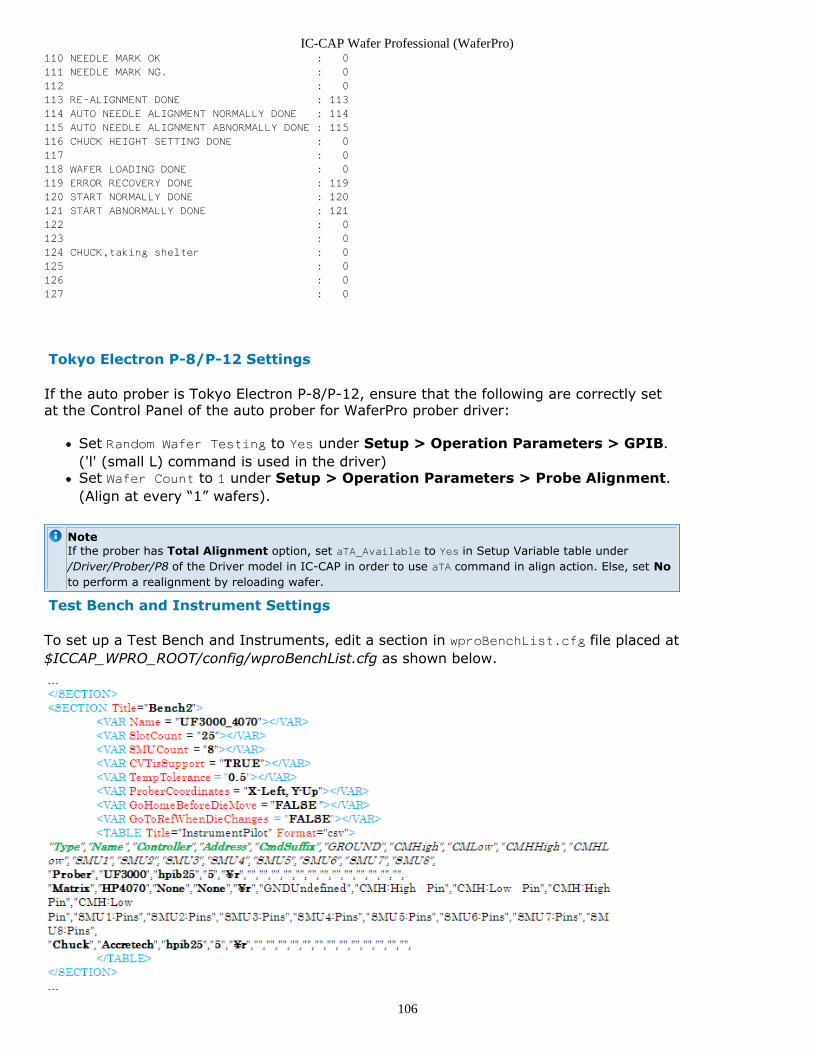
IC-CAP Wafer Professional (WaferPro)
106
110 NEEDLE MARK OK : 0
111 NEEDLE MARK NG. : 0
112 : 0
113 RE-ALIGNMENT DONE : 113
114 AUTO NEEDLE ALIGNMENT NORMALLY DONE : 114
115 AUTO NEEDLE ALIGNMENT ABNORMALLY DONE : 115
116 CHUCK HEIGHT SETTING DONE : 0
117 : 0
118 WAFER LOADING DONE : 0
119 ERROR RECOVERY DONE : 119
120 START NORMALLY DONE : 120
121 START ABNORMALLY DONE : 121
122 : 0
123 : 0
124 CHUCK,taking shelter : 0
125 : 0
126 : 0
127 : 0
Tokyo Electron P-8/P-12 Settings
If the auto prober is Tokyo Electron P-8/P-12, ensure that the following are correctly setat the Control Panel of the auto prober for WaferPro prober driver:
Set Random Wafer Testing to Yes under Setup > Operation Parameters > GPIB.('l' (small L) command is used in the driver)Set Wafer Count to 1 under Setup > Operation Parameters > Probe Alignment.(Align at every “1” wafers).
NoteIf the prober has Total Alignment option, set aTA_Available to Yes in Setup Variable table under/Driver/Prober/P8 of the Driver model in IC-CAP in order to use aTA command in align action. Else, set Noto perform a realignment by reloading wafer.
Test Bench and Instrument Settings
To set up a Test Bench and Instruments, edit a section in wproBenchList.cfg file placed at$ICCAP_WPRO_ROOT/config/wproBenchList.cfg as shown below.
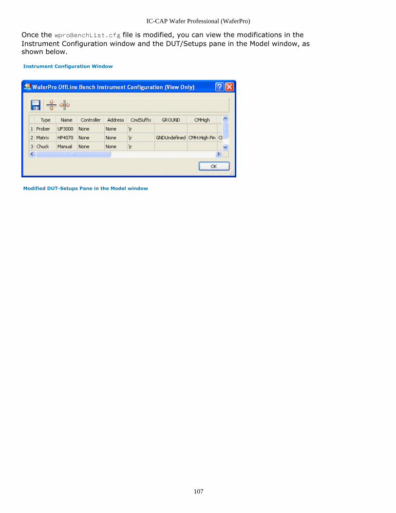
IC-CAP Wafer Professional (WaferPro)
107
Once the wproBenchList.cfg file is modified, you can view the modifications in theInstrument Configuration window and the DUT/Setups pane in the Model window, asshown below.
Instrument Configuration Window
Modified DUT-Setups Pane in the Model window
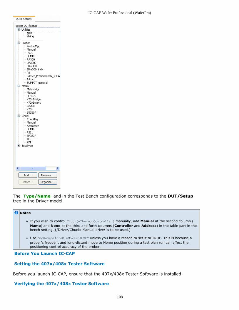
IC-CAP Wafer Professional (WaferPro)
108
The Type/Name and in the Test Bench configuration corresponds to the DUT/Setuptree in the Driver model.
Notes
If you wish to control Chuck(=Thermo Controller) manually, add Manual at the second column (Name) and None at the third and forth columns (Controller and Address) in the table part in thebench setting. (/Driver/Chuck/ Manual driver is to be used.)
Use "GoHomeBeforeDieMove=FALSE" unless you have a reason to set it to TRUE. This is because aprober’s frequent and long-distant move to Home position during a test plan run can affect thepositioning control accuracy of the prober.
Before You Launch IC-CAP
Setting the 407x/408x Tester Software
Before you launch IC-CAP, ensure that the 407x/408x Tester Software is installed.
Verifying the 407x/408x Tester Software
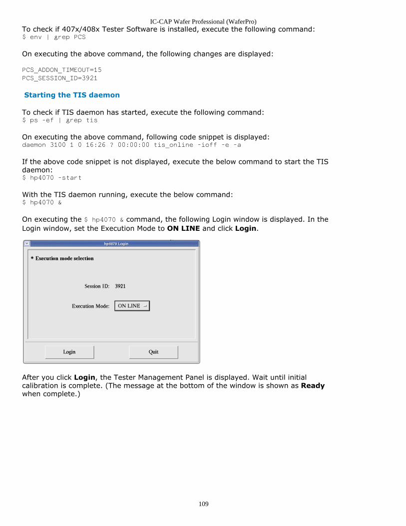
IC-CAP Wafer Professional (WaferPro)
109
To check if 407x/408x Tester Software is installed, execute the following command:$ env | grep PCS
On executing the above command, the following changes are displayed:
PCS_ADDON_TIMEOUT=15
PCS_SESSION_ID=3921
Starting the TIS daemon
To check if TIS daemon has started, execute the following command:$ ps -ef | grep tis
On executing the above command, following code snippet is displayed:daemon 3100 1 0 16:26 ? 00:00:00 tis_online -ioff -e -a
If the above code snippet is not displayed, execute the below command to start the TISdaemon:$ hp4070 -start
With the TIS daemon running, execute the below command:$ hp4070 &
On executing the $ hp4070 & command, the following Login window is displayed. In theLogin window, set the Execution Mode to ON LINE and click Login.
After you click Login, the Tester Management Panel is displayed. Wait until initialcalibration is complete. (The message at the bottom of the window is shown as Readywhen complete.)
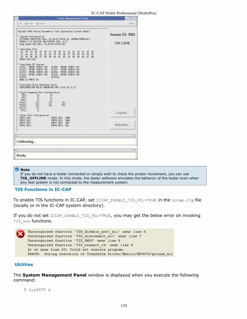
IC-CAP Wafer Professional (WaferPro)
110
NoteIf you do not have a tester connected or simply wish to check the prober movement, you can useTIS_OFFLINE mode. In this mode, the tester software emulates the behavior of the tester even whenany test system is not connected to the measurement system.
TIS Functions in IC-CAP
To enable TIS functions in IC-CAP, set ICCAP_ENABLE_TIS_PEL=TRUE in the iccap.cfg file(locally or in the IC-CAP system directory).
If you do not set ICCAP_ENABLE_TIS_PEL=TRUE, you may get the below error on invokingTIS_xxx functions.
Utilities
The System Management Panel window is displayed when you execute the followingcommand:
$ sys4070 &
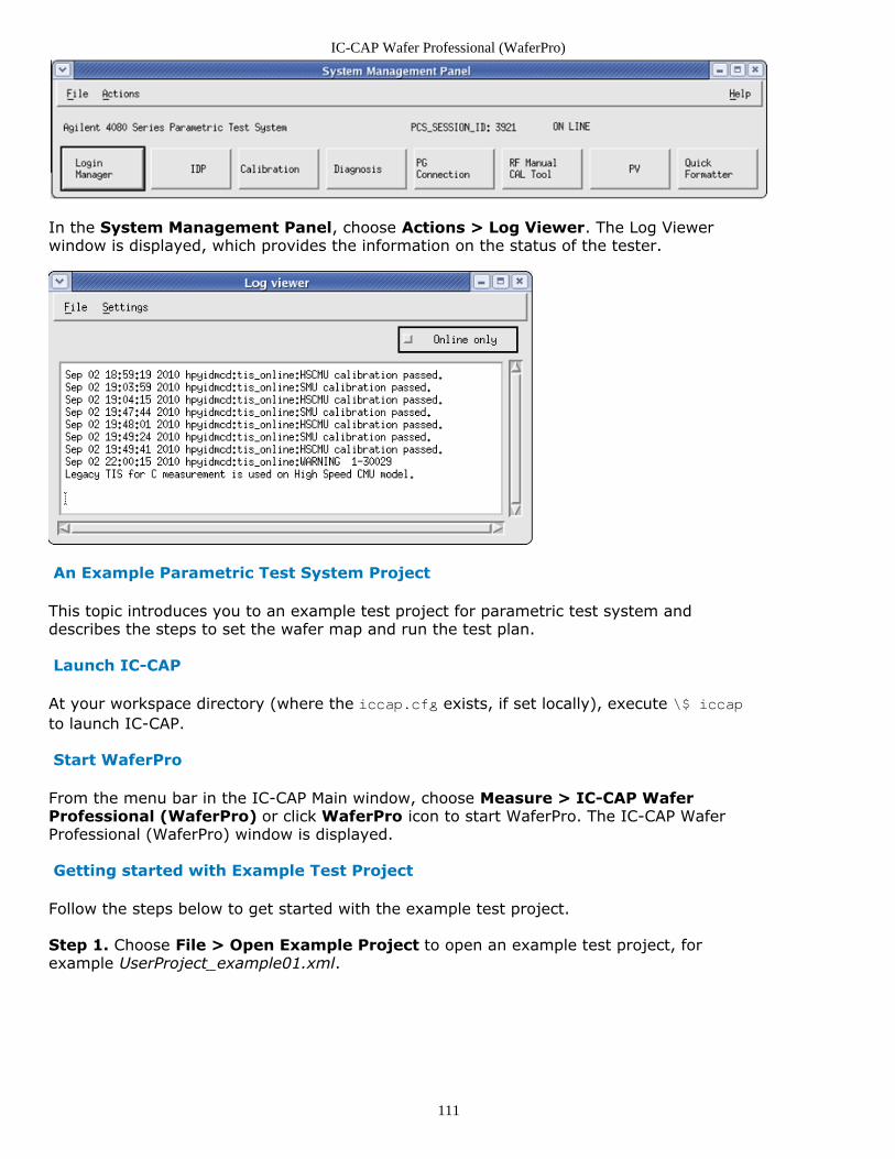
IC-CAP Wafer Professional (WaferPro)
111
In the System Management Panel, choose Actions > Log Viewer. The Log Viewerwindow is displayed, which provides the information on the status of the tester.
An Example Parametric Test System Project
This topic introduces you to an example test project for parametric test system anddescribes the steps to set the wafer map and run the test plan.
Launch IC-CAP
At your workspace directory (where the iccap.cfg exists, if set locally), execute \$ iccapto launch IC-CAP.
Start WaferPro
From the menu bar in the IC-CAP Main window, choose Measure > IC-CAP WaferProfessional (WaferPro) or click WaferPro icon to start WaferPro. The IC-CAP WaferProfessional (WaferPro) window is displayed.
Getting started with Example Test Project
Follow the steps below to get started with the example test project.
Step 1. Choose File > Open Example Project to open an example test project, forexample UserProject_example01.xml.
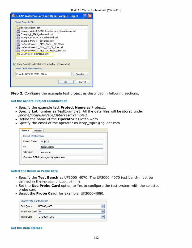
IC-CAP Wafer Professional (WaferPro)
112
Step 2. Configure the example test project as described in following sections.
Set the General Project Identification
Specify the example test Project Name as Project1.Specify Lot number as TestExample3. All the data files will be stored under/home/iccapuser/ace/data/TestExample3.Define the name of the Operator as iccap wpro.Specify the email of the operator as [email protected]
Select the Bench or Probe Card
Specify the Test Bench as UF3000_4070. The UF3000_4070 test bench must bedefined in the WproBenchList.cfg file.Set the Use Probe Card option to Yes to configure the test system with the selectedprobe card.Select the Probe Card, for example, UF3000-4080.
Set the Data Storage
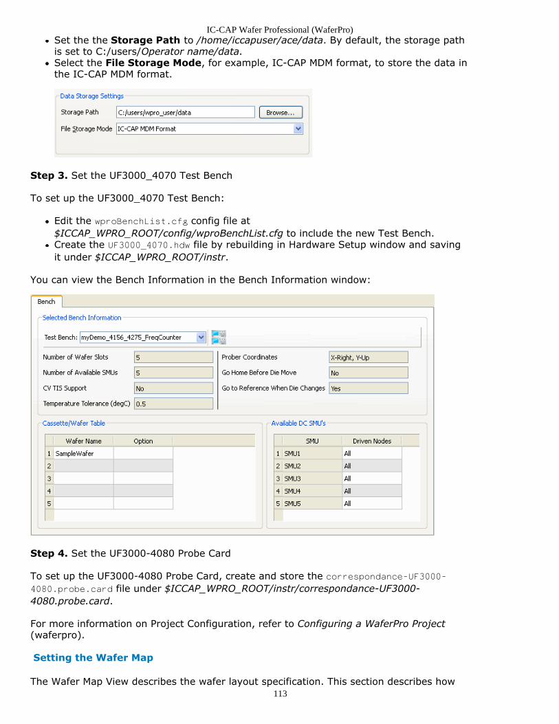
IC-CAP Wafer Professional (WaferPro)
113
Set the the Storage Path to /home/iccapuser/ace/data. By default, the storage pathis set to C:/users/Operator name/data.Select the File Storage Mode, for example, IC-CAP MDM format, to store the data inthe IC-CAP MDM format.
Step 3. Set the UF3000_4070 Test Bench
To set up the UF3000_4070 Test Bench:
Edit the wproBenchList.cfg config file at$ICCAP_WPRO_ROOT/config/wproBenchList.cfg to include the new Test Bench.Create the UF3000_4070.hdw file by rebuilding in Hardware Setup window and savingit under $ICCAP_WPRO_ROOT/instr.
You can view the Bench Information in the Bench Information window:
Step 4. Set the UF3000-4080 Probe Card
To set up the UF3000-4080 Probe Card, create and store the correspondance-UF3000-4080.probe.card file under $ICCAP_WPRO_ROOT/instr/correspondance-UF3000-4080.probe.card.
For more information on Project Configuration, refer to Configuring a WaferPro Project(waferpro).
Setting the Wafer Map
The Wafer Map View describes the wafer layout specification. This section describes how
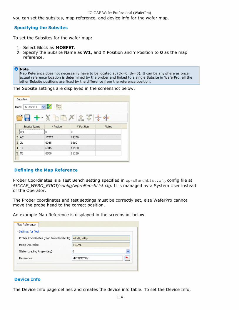
IC-CAP Wafer Professional (WaferPro)
114
you can set the subsites, map reference, and device info for the wafer map.
Specifying the Subsites
To set the Subsites for the wafer map:
Select Block as MOSFET.1.Specify the Subsite Name as W1, and X Position and Y Position to 0 as the map2.reference.
NoteMap Reference does not necessarily have to be located at (dx=0, dy=0). It can be anywhere as onceactual reference location is determined by the prober and linked to a single Subsite in WaferPro, all theother Subsite positions are fixed by the difference from the reference position.
The Subsite settings are displayed in the screenshot below.
Defining the Map Reference
Prober Coordinates is a Test Bench setting specified in wproBenchList.cfg config file at$ICCAP_WPRO_ROOT/config/wproBenchList.cfg. It is managed by a System User insteadof the Operator.
The Prober coordinates and test settings must be correctly set, else WaferPro cannotmove the probe head to the correct position.
An example Map Reference is displayed in the screenshot below.
Device Info
The Device Info page defines and creates the device info table. To set the Device Info,
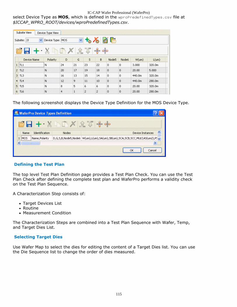
IC-CAP Wafer Professional (WaferPro)
115
select Device Type as MOS, which is defined in the wproPredefinedTypes.csv file at$ICCAP_WPRO_ROOT/devices/wproPredefinedTypes.csv.
The following screenshot displays the Device Type Definition for the MOS Device Type.
Defining the Test Plan
The top level Test Plan Definition page provides a Test Plan Check. You can use the TestPlan Check after defining the complete test plan and WaferPro performs a validity checkon the Test Plan Sequence.
A Characterization Step consists of:
Target Devices ListRoutineMeasurement Condition
The Characterization Steps are combined into a Test Plan Sequence with Wafer, Temp,and Target Dies List.
Selecting Target Dies
Use Wafer Map to select the dies for editing the content of a Target Dies list. You can usethe Die Sequence list to change the order of dies measured.
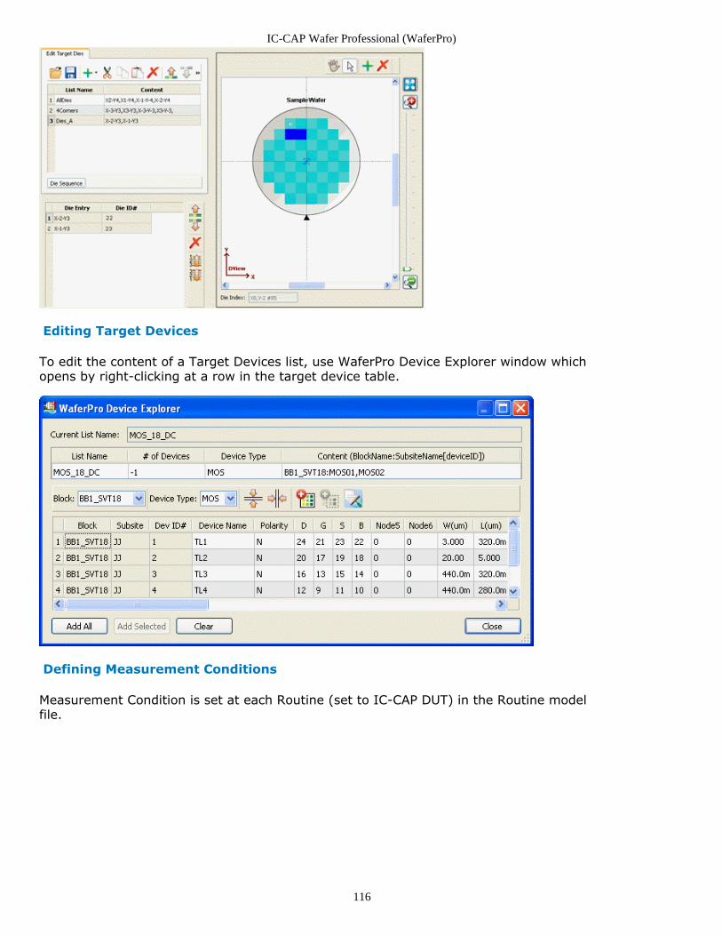
IC-CAP Wafer Professional (WaferPro)
116
Editing Target Devices
To edit the content of a Target Devices list, use WaferPro Device Explorer window whichopens by right-clicking at a row in the target device table.
Defining Measurement Conditions
Measurement Condition is set at each Routine (set to IC-CAP DUT) in the Routine modelfile.
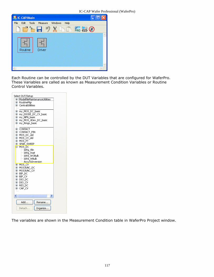
IC-CAP Wafer Professional (WaferPro)
117
Each Routine can be controlled by the DUT Variables that are configured for WaferPro.These Variables are called as known as Measurement Condition Variables or RoutineControl Variables.
The variables are shown in the Measurement Condition table in WaferPro Project window.
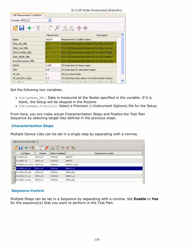
IC-CAP Wafer Professional (WaferPro)
118
Set the following two variables:
$SetupName_MNL: Data is measured at the Nodes specified in the variable. If it isblank, the Setup will be skipped in the Routine.$SetupName_Precision: Select a Precision (=Instrument Options) file for the Setup.
From here, you are make actual Characterization Steps and finalize the Test PlanSequence by selecting target lists defined in the previous steps.
Characterization Steps
Multiple Device Lists can be set in a single step by separating with a comma.
Sequence Control
Multiple Steps can be set in a Sequence by separating with a comma. Set Enable to Yesfor the sequence(s) that you want to perform in the Test Plan.
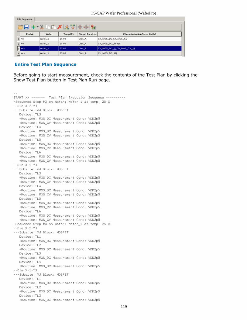
IC-CAP Wafer Professional (WaferPro)
119
Entire Test Plan Sequence
Before going to start measurement, check the contents of the Test Plan by clicking theShow Test Plan button in Test Plan Run page.
--
START >> ------- Test Plan Execution Sequence ----------
-Sequence Step #3 on Wafer: Wafer_1 at temp: 25 C
--Die X-2-Y3
---Subsite: JJ Block: MOSFET
Device: TL3
+Routine: MOS_DC Measurement Cond: VDD2p5
+Routine: MOS_CV Measurement Cond: VDD2p5
Device: TL4
+Routine: MOS_DC Measurement Cond: VDD2p5
+Routine: MOS_CV Measurement Cond: VDD2p5
Device: TL5
+Routine: MOS_DC Measurement Cond: VDD2p5
+Routine: MOS_CV Measurement Cond: VDD2p5
Device: TL6
+Routine: MOS_DC Measurement Cond: VDD2p5
+Routine: MOS_CV Measurement Cond: VDD2p5
--Die X-1-Y3
---Subsite: JJ Block: MOSFET
Device: TL3
+Routine: MOS_DC Measurement Cond: VDD2p5
+Routine: MOS_CV Measurement Cond: VDD2p5
Device: TL4
+Routine: MOS_DC Measurement Cond: VDD2p5
+Routine: MOS_CV Measurement Cond: VDD2p5
Device: TL5
+Routine: MOS_DC Measurement Cond: VDD2p5
+Routine: MOS_CV Measurement Cond: VDD2p5
Device: TL6
+Routine: MOS_DC Measurement Cond: VDD2p5
+Routine: MOS_CV Measurement Cond: VDD2p5
-Sequence Step #4 on Wafer: Wafer_1 at temp: 25 C
--Die X-2-Y3
---Subsite: MJ Block: MOSFET
Device: TL1
+Routine: MOS_DC Measurement Cond: VDD2p5
Device: TL2
+Routine: MOS_DC Measurement Cond: VDD2p5
Device: TL3
+Routine: MOS_DC Measurement Cond: VDD2p5
Device: TL4
+Routine: MOS_DC Measurement Cond: VDD2p5
--Die X-1-Y3
---Subsite: MJ Block: MOSFET
Device: TL1
+Routine: MOS_DC Measurement Cond: VDD2p5
Device: TL2
+Routine: MOS_DC Measurement Cond: VDD2p5
Device: TL3
+Routine: MOS_DC Measurement Cond: VDD2p5
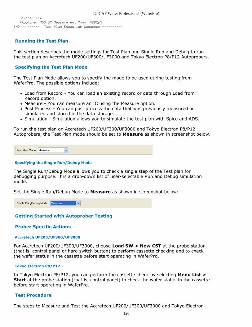
IC-CAP Wafer Professional (WaferPro)
120
Device: TL4
+Routine: MOS_DC Measurement Cond: VDD2p5
END >> ------ Test Plan Execution Sequence ----------
--
Running the Test Plan
This section describes the mode settings for Test Plan and Single Run and Debug to runthe test plan on Accretech UF200/UF300/UF3000 and Tokyo Electron P8/P12 Autoprobers.
Specifying the Test Plan Mode
The Test Plan Mode allows you to specify the mode to be used during testing fromWaferPro. The possible options include:
Load from Record - You can load an existing record or data through Load fromRecord option.Measure - You can measure an IC using the Measure option.Post Process - You can post process the data that was previously measured orsimulated and stored in the data storage.Simulation - Simulation allows you to simulate the test plan with Spice and ADS.
To run the test plan on Accretech UF200/UF300/UF3000 and Tokyo Electron P8/P12Autoprobers, the Test Plan mode should be set to Measure as shown in screenshot below.
Specifying the Single Run/Debug Mode
The Single Run/Debug Mode allows you to check a single step of the Test plan fordebugging purpose. It is a drop-down list of user-selectable Run and Debug simulationmode.
Set the Single Run/Debug Mode to Measure as shown in screenshot below:
Getting Started with Autoprober Testing
Prober Specific Actions
Accretech UF200/UF300/UF3000
For Accretech UF200/UF300/UF3000, choose Load SW > New CST at the probe station(that is, control panel or hard switch button) to perform cassette checking and to checkthe wafer status in the cassette before start operating in WaferPro.
Tokyo Electron P8/P12
In Tokyo Electron P8/P12, you can perform the cassette check by selecting Menu List >Start at the probe station (that is, control panel) to check the wafer status in the cassettebefore start operating in WaferPro.
Test Procedure
The steps to Measure and Test the Accretech UF200/UF300/UF3000 and Tokyo Electron
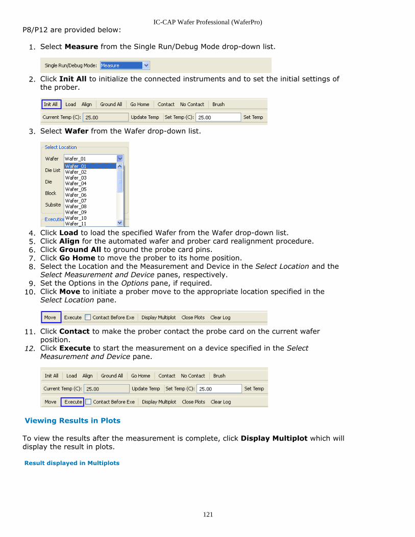
IC-CAP Wafer Professional (WaferPro)
121
P8/P12 are provided below:
Select Measure from the Single Run/Debug Mode drop-down list.1.
Click Init All to initialize the connected instruments and to set the initial settings of2.the prober.
Select Wafer from the Wafer drop-down list.3.
Click Load to load the specified Wafer from the Wafer drop-down list.4.Click Align for the automated wafer and prober card realignment procedure.5.Click Ground All to ground the probe card pins.6.Click Go Home to move the prober to its home position.7.Select the Location and the Measurement and Device in the Select Location and the8.Select Measurement and Device panes, respectively.Set the Options in the Options pane, if required.9.Click Move to initiate a prober move to the appropriate location specified in the10.Select Location pane.
Click Contact to make the prober contact the probe card on the current wafer11.position.Click Execute to start the measurement on a device specified in the Select12.Measurement and Device pane.
Viewing Results in Plots
To view the results after the measurement is complete, click Display Multiplot which willdisplay the result in plots.
Result displayed in Multiplots
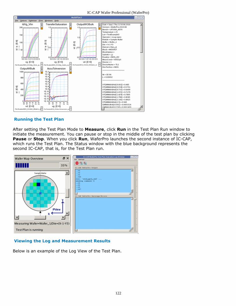
IC-CAP Wafer Professional (WaferPro)
122
Running the Test Plan
After setting the Test Plan Mode to Measure, click Run in the Test Plan Run window toinitiate the measurement. You can pause or stop in the middle of the test plan by clickingPause or Stop. When you click Run, WaferPro launches the second instance of IC-CAP,which runs the Test Plan. The Status window with the blue background represents thesecond IC-CAP, that is, for the Test Plan run.
Viewing the Log and Measurement Results
Below is an example of the Log View of the Test Plan.
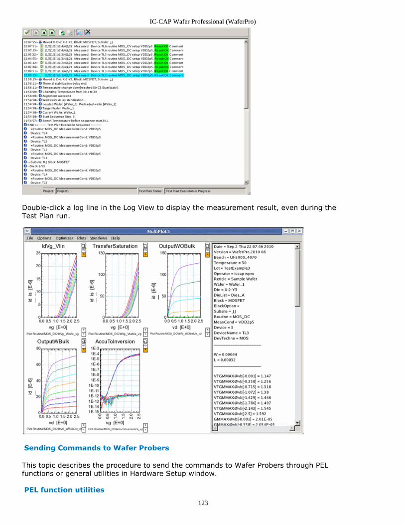
IC-CAP Wafer Professional (WaferPro)
123
Double-click a log line in the Log View to display the measurement result, even during theTest Plan run.
Sending Commands to Wafer Probers
This topic describes the procedure to send the commands to Wafer Probers through PELfunctions or general utilities in Hardware Setup window.
PEL function utilities
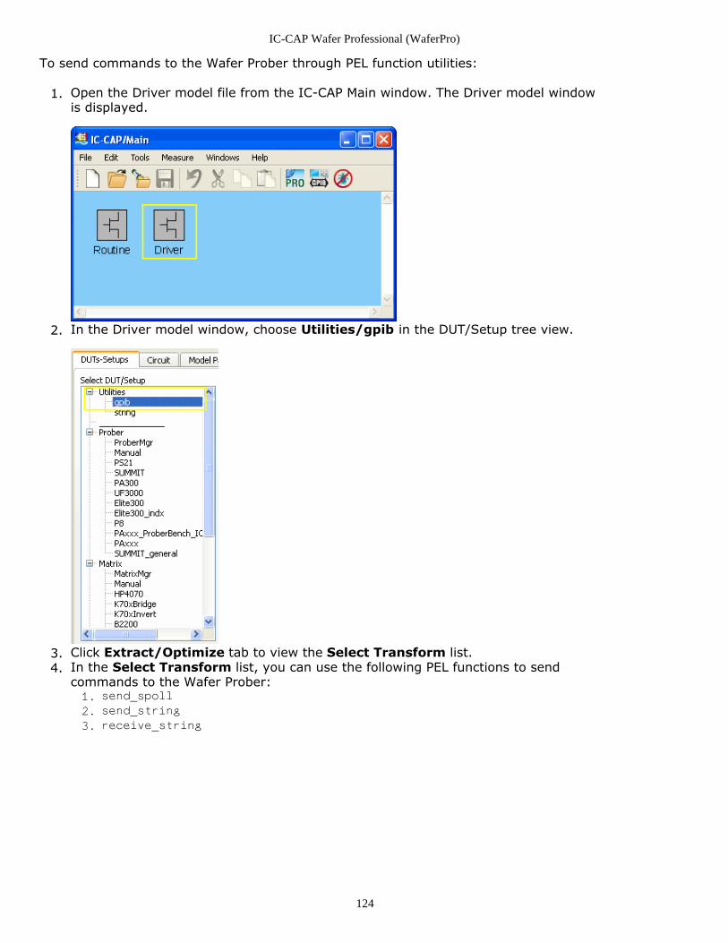
IC-CAP Wafer Professional (WaferPro)
124
To send commands to the Wafer Prober through PEL function utilities:
Open the Driver model file from the IC-CAP Main window. The Driver model window1.is displayed.
In the Driver model window, choose Utilities/gpib in the DUT/Setup tree view.2.
Click Extract/Optimize tab to view the Select Transform list.3.In the Select Transform list, you can use the following PEL functions to send4.commands to the Wafer Prober:
send_spoll
1.
send_string
2.
receive_string
3.
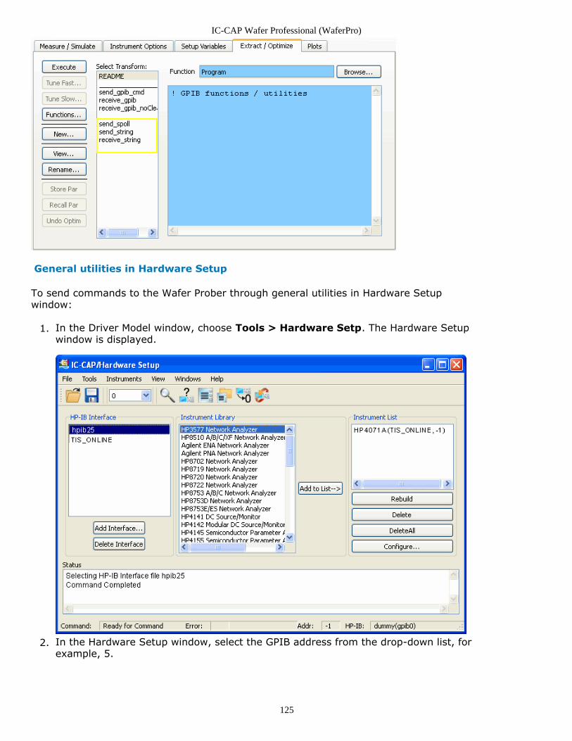
IC-CAP Wafer Professional (WaferPro)
125
General utilities in Hardware Setup
To send commands to the Wafer Prober through general utilities in Hardware Setupwindow:
In the Driver Model window, choose Tools > Hardware Setp. The Hardware Setup1.window is displayed.
In the Hardware Setup window, select the GPIB address from the drop-down list, for2.example, 5.
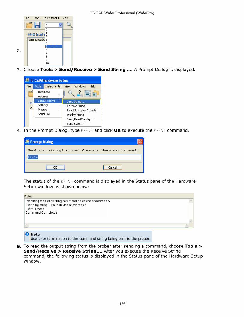
IC-CAP Wafer Professional (WaferPro)
126
2.
Choose Tools > Send/Receive > Send String …. A Prompt Dialog is displayed.3.
In the Prompt Dialog, type E\r\n and click OK to execute the E\r\n command.4.
The status of the E\r\n command is displayed in the Status pane of the HardwareSetup window as shown below:
NoteUse \r\n termination to the command string being sent to the prober.
To read the output string from the prober after sending a command, choose Tools >5.Send/Receive > Receive String.... After you execute the Receive Stringcommand, the following status is displayed in the Status pane of the Hardware Setupwindow.
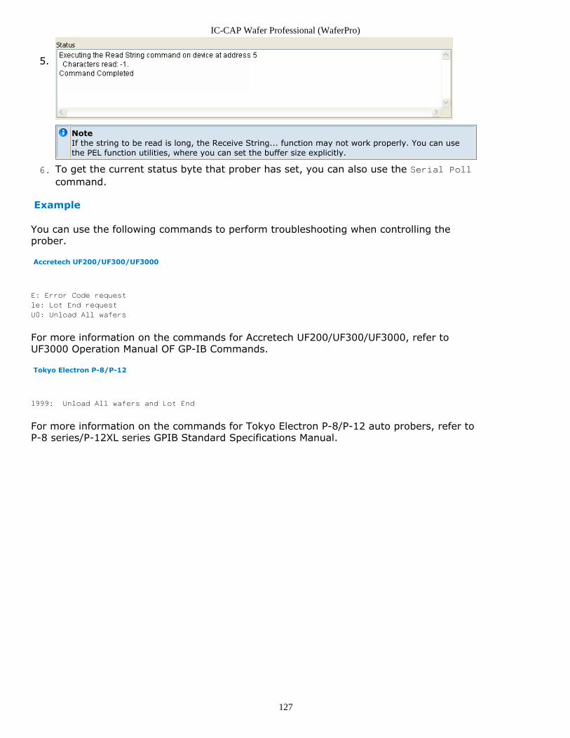
IC-CAP Wafer Professional (WaferPro)
127
5.
NoteIf the string to be read is long, the Receive String... function may not work properly. You can usethe PEL function utilities, where you can set the buffer size explicitly.
To get the current status byte that prober has set, you can also use the Serial Poll6.
command.
Example
You can use the following commands to perform troubleshooting when controlling theprober.
Accretech UF200/UF300/UF3000
E: Error Code request
le: Lot End request
U0: Unload All wafers
For more information on the commands for Accretech UF200/UF300/UF3000, refer toUF3000 Operation Manual OF GP-IB Commands.
Tokyo Electron P-8/P-12
l999: Unload All wafers and Lot End
For more information on the commands for Tokyo Electron P-8/P-12 auto probers, refer toP-8 series/P-12XL series GPIB Standard Specifications Manual.