
James Walker - O Rings
32
‘O’ Ring Guide High Performance Sealing Technology The comprehensive guide to ‘O’ ring sealing systems including • ‘O’ ring selection • General & high performance materials • Housing design & tolerances • Cords, kits & lubricants Issue 6
Transcript of James Walker - O Rings

‘O’ Ring Guide
High Performance Sealing Technology
The comprehensive guide to ‘O’ ringsealing systems including• ‘O’ ring selection• General & high performance materials• Housing design & tolerances• Cords, kits & lubricants
Issue 6

To order or get further details, call your local contact shown on rear cover or listed at www.jameswalker.biz2
‘O’ Ring Guide
Introduction
The ‘O’ ring, or toroidal seal, is an exceptionally versatile sealing device. Applications, ranging from garden hose couplings to aerospace or oil and gas duties, make it the world’s most popular volume-produced seal.
‘O’ rings offer many benefits to designers, engineers, maintenance staff and plant operators, they:
l Suit many static and dynamic applications.
l Are very compact and occupy little space.
l Seal efficiently in both directions.l Can work between -65°C and +325°C
when made of elastomer — according to material type.
l Can function at temperatures down to -200°C when made of PTFE.
Today, the design engineer is faced with a bewildering array of ‘O’ ring statistics and advice. In this guide we simplify the design data, give concise information on materials and facilitate part selection for specification and ordering purposes.
‘O’ ring stocks & availability
We stock many thousands of types and sizes of ‘O’ rings in our most popular materials — including rapid gas decompression (RGD) resistant grades — ready for same day despatch.
If the rings you want are not available off-the-shelf, we can precision manufacture them within hours, if necessary. With our ‘lean’ manufacturing plant and flexible production schedules, we can meet industry’s most urgent requests.
Quality
Standards and approvalsOur Quality System is third-party certified to the latest versions of both the Aerospace standard BS EN 9100 and to BS EN ISO 9001.
Moreover, we are regularly assessed and quality approved by a wide range of industry bodies and individual customers, including multinational corporations, utilities and government organisations. An ISO 2230 compliant package is offered as standard.
We also hold test equipment for all relevant BS, ISO, ASA, API, ANSI, DIN, DTD and NATO standards. Certificates of conformity are supplied on request.
In-house facilities include specialised equipment for rapid gas decompression (RGD) testing, including qualification to Norsok M-710 Annex B (see page 11).
Packaging and labelling is available to customers’ individual specifications.
Material Safety Data Sheets (MSDS) are available for every product we supply.

To order or get further details, call your local contact shown on rear cover or listed at www.jameswalker.biz 3
‘O’ Ring Guide
Contents PageHow to use this guideSelecting an ‘O’ ring 4Selecting a back-up ring 5Selecting a material 6How to order 7
Materials & propertiesGeneral materials 8High performance materials 9Guide to material use 10Service grades 10Rapid gas decompression 11FEP encapsulated ‘O’ rings 12Back-up rings 12
James Walker ‘O’ ringsChart 50: inch & metric sizes 13-16‘O’ rings for pipe fittings 16Aerospace sizes to BS ISO 3601-1 17-20Chart 72: metric sizes 21-22 Chart 17000: inch sizes 23Non-standard sizes 24
Complementary productsColoured materials 25‘O’ ring cord 25Commercial quality ‘O’ rings 25‘O’ ring kits 26Special packaging & kits 26‘O’ ring lubricants 26
General design notes 27-28Housing design 29-31General information 31Contact details 32
Quality production and inspectionOur Materials Technology Centre houses one of Europe’s most advanced facilities for elastomer batch production. At its heart is a computer-controlled internal mixer that holds formulae for all our elastomeric compounds — well over 300 in total.
Together with on-line rheometer testing, this gives us complete batch traceability, regardless of any release certificate requirements.
The post-curing of silicone and fluorocarbon elastomers is also under microprocessor control for temperature and time. Each cure cycle is recorded and is traceable as a vital link in our quality chain.
Every ‘O’ ring manufactured by James Walker is visually inspected by a dedicated human inspector, or an automated optical inspection system, to the appropriate grade requirements ofBS ISO 3601-3. Each production batch of seals is further dimensionally verified using our highly accurate and reproducible optical inspection systems.
These state-of-the-art optical systems are the Micro-Vu and fully-automated BaslerVario2, both of which offer sub-micronresolution with exceptional repeatability.
Micro-Vu optical inspection system
Basler Vario2 fully-automated inspection system
To order or get further details, call your local contact shown on rear cover or listed at www.jameswalker.biz4
How to use this guide
Selecting an ‘O’ ring
This guide contains four size charts:l Chart 50: including BS 1806,
SAE AS 586, and BS ISO 3601-1 (non-aerospace). Note: BS 1806 has been superseded by BS ISO 3601-1 and BS ISO 3601-2.
l Aerospace sizes to BS ISO 3601-1.l Chart 72: metric sizes to BS 4518. l Chart 17000: James Walker inch sizes.
To match an existing ‘O’ ringIf your existing ‘O’ ring has a reference of BS 1806, BS ISO 3601-1, SAE AS 568, or BS 4518:
1) Refer to Chart 50 for BS 1806,BS ISO 3601-1 (non-aerospace), and SAE AS568. Then quote appropriate James Walker number.
2) Refer to Aerospace Sizes to BS ISO 3601-1 for rings to this aerospace standard. Then quote the appropriate size code.
3) Refer to Chart 72 for BS 4518. Then quote the appropriate James Walker number.
If you have a JW Chart 17000 reference for an ‘O’ ring, please quote that number.
Diameter sections ‘A’ used in charts
Chart 50(BS 1806,
BS ISO 3601-1,
SAE AS 568)
Aerospacesizes toBS ISO 3601-1
Chart 72(BS 4518)
Chart17000
0.070" 1.78mm
0.071"1.80mm 1.6mm 0.063"
0.103"2.62mm
0.104"2.65mm 2.4mm 0.094"
0.139"3.53mm
0.140"3.55mm 3.0mm 0.125"
0.210"5.33mm
0.209"5.30mm 5.7mm 0.188"
0.275"6.99mm
0.276"7.00mm 8.4mm 0.250"
If only the size is known1) Obtain diameter section A of ‘O’ ring.
2) Consult table (above) to find the Chart that covers the appropriate diameter section A.
3) Consult appropriate Chart (pages 13-23), under the specific diameter section A.
4) Obtain inside diameter B of ring.
5) Refer to column on Chart that lists B and identify your existing ‘O’ ring.
6) Quote the appropriate part number.
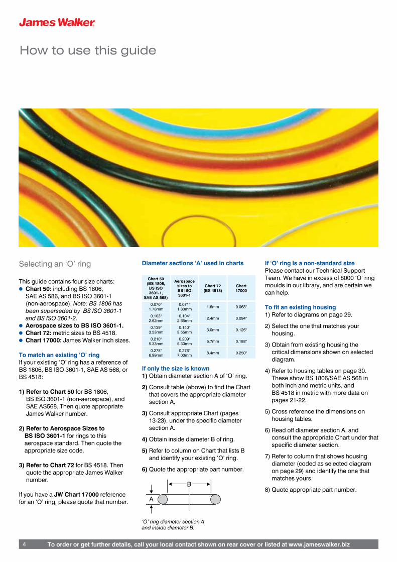
‘O’ ring diameter section A and inside diameter B.
If ‘O’ ring is a non-standard sizePlease contact our Technical Support Team. We have in excess of 8000 ‘O’ ring moulds in our library, and are certain we can help.
To fit an existing housing 1) Refer to diagrams on page 29.
2) Select the one that matches your housing.
3) Obtain from existing housing the critical dimensions shown on selected diagram.
4) Refer to housing tables on page 30. These show BS 1806/SAE AS 568 in both inch and metric units, and BS 4518 in metric with more data on pages 21-22.
5) Cross reference the dimensions on housing tables.
6) Read off diameter section A, and consult the appropriate Chart under that specific diameter section.
7) Refer to column that shows housing diameter (coded as selected diagram on page 29) and identify the one that matches yours.
8) Quote appropriate part number.
A
B

To order or get further details, call your local contact shown on rear cover or listed at www.jameswalker.biz 5
How to use this guide
For new applications1) Refer to Design sections, pages
27-31, for guidance with regard to applications.
2) For aerospace equipment, select ‘O’ ring from Aerospace Sizes to BS ISO 3601-1, pages 17-20.
3) For general metric equipment, select ‘O’ ring from Chart 72, pages 21-22.
4) If the metric size you require is not available from Chart 72, then select from the metric columns in Chart 50, pages 13-16.
5) For general inch sizes, use Chart 50, or Chart 17000 on page 23.
Selecting a back-up ring
One or more back-up rings are used to prevent extrusion of an elastomeric ‘O’ ring under arduous operating conditions.
Our standard back-up rings are machined in PTFE and normally supplied in single turn or spiral form. See page 12 for more details on back-up rings.
Back-up rings for use with James Walker ‘O’ ring numberRefer to How to order section on page 7 for precise specification details relating to back-up rings for Chart 50, Chart 72 and Chart 17000 applications.
Back-up ring for use with existing ‘O’ ring1) Identify appropriate Chart and part
number for existing ‘O’ ring. (Note: If a standard ‘O’ ring has been used on a non-standard shaft or cylinder — ie, compressed or stretched into place — the equivalent standard back-up ring must not be used as it cannot be stretched or squeezed in the same way.)
2) Refer to How to order section on page 7 for precise specification details.
Back-up ring for use with non-standard size ‘O’ ringPlease contact our Technical Support Team for recommendations on the correct back-up ring.
Back-up ring for a new application1) Select the ‘O’ ring you require from
our Charts, using the method outlined earlier on this page.
2) Refer to How to order section on page 7 for precise specification details.

To order or get further details, call your local contact shown on rear cover or listed at www.jameswalker.biz6
How to use this guide
Selecting a material
Stocked material gradesStandard compound
reference Rubber type Specifications Stocked Colour ASTM D2000 reference
PB80 ‘Medium’ nitrile (NBR) BS6996 Grade BO80 ✓ BlackASTM D2000 M2BG 810, B14, EF11 , EF21, EO14, EO34. BS5176 2MBG 810, B14, E14, E34, E51, E61
EP18/H/75 Ethylene-propylene (EPM) ✓ Black ASTM D2000 M3BA 810, A14, B13, Z1.Z1: Hardness 75±5 IRHD
FR10/80 Fluorocarbon (FKM) DTD 5612A Grade 80** ✓ Black ASTM D2000 M6HK 810, A1-10, B36
FR25/90* Fluorocarbon (FKM) ✓ Black ASTM D2000 M7HK 914, B38, Z1
FR58/90* Fluorocarbon (FKM) ✓ Black ASTM D2000 M3HK 910, A1-10, B38, Z1
Elast-O-Lion® 101* Hydrogenated nitrile (HNBR) ✓ Black
Elast-O-Lion® 180 Hydrogenated nitrile (HNBR) ✓ Black
Elast-O-Lion® 985* Hydrogenated nitrile (HNBR) ✓ Black
SIL 80/2 Silicone (VMQ) BS F153 Grade 80 ✓ White
ASTM D2000 7GE 805, A19, B37, EO36, Z1Z1: colour whiteBS5176 2MGE 805 A19, B17, Z1Z1: colour white
*These grades are compounded for Rapid Gas Decompression (RGD) resistance: please consult our Technical Support Team for specific details.** All DTD specifications have been declared obsolescent. Red: Please specify on your enquiry or order if you want ‘O’ rings to meet these specifications.
The Stocked material grades table, above, gives details of our nine most widely demanded stocked materials. We recommend that you use one of these, wherever possible, for your ‘O’ rings. Full details of all readily available materials and their chemical compatibility are given on pages 8-12.
‘O’ ring sizes shown on Chart 50, Aerospace sizes to BS ISO 3601-1, Chart 72, and Chart 17000 are supplied without mould charges.
If you have any doubts about materials selection, please contact our Technical Support Team for recommendations.

To order or get further details, call your local contact shown on rear cover or listed at www.jameswalker.biz 7
How to use this guide
How to order
The following information and examples will help you to order the correct ‘O’ ring and back-up ring for specific applications. For critical applications, including those requiring FEP encapsulated ‘O’ rings, we recommend that you state the following details to enable us to ensure suitability:
l Pressures and pressure media.l Operating temperatures.l Static, or dynamic operation with
speed.l Housing type.l Tolerances.l Any other important factors.
‘O’ ringsStandard sizes Charts 50, 72 & 17000: please state the JW number followed by material reference. If no material or application conditions are specified, we will supply our PB80 nitrile grade.
EXAMPLE: JW 50-001 PB80.
Aerospace sizes to BS ISO 3601-1: please use the following example, where XXXX denotes Size Code, YYY denotes ID, and ZZZ denotes cross-section diameter.
EXAMPLE: ‘O’ ring – BS ISO 3601-1A-XXXX – YYY x ZZZ – S, in FR10/80 to DTD 5612A Grade 80.
Other sizes: please state ID, cross-section diameter and material.
EXAMPLE: ID 49.4mm, DS 4.1mm, PB80
Back-up ringsBack-up rings are supplied in spiral form unless single turn is stated. Also, they are supplied in PTFE unless otherwise stated.
Back-up ring for Chart 50 inch sizes: for back-up rings to fit inch size shafts and cylinders, state the JW number for the ‘O’ ring. Also indicate spiral or single turn, and material.
EXAMPLE: For a JW 50-433 (0.275” diameter section) ‘O’ ring on a 5½” OD shaft or 6” ID cylinder, order JW 50-433 PTFE spiral back-up ring.
Back-up rings for Chart 50 metric sizes: When ordering back-up rings to match our suggested Chart 50 metric shaft and cylinder sizes, please use:
l Prefix 150 for shaft applications.l Prefix 250 for cylinder applications.l Also indicate spiral or single turn and
material.
(The reason is that ‘O’ rings can be stretched or squeezed slightly — see General design notes on pages 27-28 — but the back-up ring must be manufactured exactly to suit the shaft or cylinder.)
EXAMPLE 1: For 140mm OD shaft, order JW 150-433 PTFE spiral back-up ring.
EXAMPLE: For 155mm ID cylinder, order JW 250-433 PTFE spiral back-up ring.
Back-up rings for Aerospace Sizes to BS ISO 3601-1: Please contact our Technical Support Team for back-up rings to BS ISO 3601-4.
Back-up rings for Chart 72: When ordering back-up rings (which cover those to BS 5106) please state the same JW 72 number as the ‘O’ ring. Also indicate spiral or single turn, and material.
EXAMPLE: JW 72-1393-57 PTFE spiral back-up ring.
Back-up rings for other sizes: When ordering back-up rings to match ‘O’ rings that are not listed in our charts, please state the following:
1) Spiral or single turn, and material.
2) Back-up ring dimensions, if known, or
3) ‘O’ ring inside diameter B; ‘O’ ring section diameter A; shaft or cylinder diameter (C or D); housing width and depth (E and F) — see page 29.
EXAMPLE: PTFE spiral back-up ring to use with a 49.4mm ID x 4.1mm DS ‘O’ ring on a 50mm diameter shaft. Housing width 7.1mm, depth 3.5mm.
Note: Back-up rings are manufactured to suit housing sizes, rather than 'O' ring sizes. Therefore back-up rings cannot be supplied based on ‘O’ ring dimensions alone.
Subsequent ordersWhen re-ordering from James Walker, please state the Re-Order Part Number (eg, OB03400X) shown on our documentation that acknowledges your previous order. This will ensure the swiftest service.
‘O’ ring diameter section A andinside diameter B.
A
B

To order or get further details, call your local contact shown on rear cover or listed at www.jameswalker.biz8
Materials & properties
General materials
Note: Materials for stocked ‘O’ rings are printed in red. For specific details please see Selecting a material on page 6.
Nitrile — acrylonitrile-butadiene (NBR) Stocked grade: PB80We have a very wide range of compounds based on various acrylonitrile/butadiene ratios. Higher nitrile content generally gives better hydrocarbon resistance, whereas lower acrylonitrile content gives better low temperature flexibility. Our PB range is suitable for use with mineral oils — particularly hydraulic types — as well as water and some solvents. Our Proteus range is generally suitable for aqueous food applications, but please consult our Technical Support Team on specific applications before ordering.
Chloroprene (CR) — eg, neoprene These general purpose elastomers are largely unaffected by sunlight and atmospheric ageing. They give satisfactory service in many media, such as mineral lubricating oils and greases, dilute acids and alkalis, and some solvents.
Natural rubber (NR)Materials based on natural rubber have high strength and high resilience with good abrasion resistance. They are suitable for use with hot and cold water, ammonia, ethylene glycol, and dilute acids and alkalis. Limited resistance to heat, weathering, and oils has reduced the use of natural rubbers in favour of synthetic elastomers.
Ethylene-propylene (EPM, EPDM)Stocked grade: EP18/H/75These compounds have excellent resistance to weathering, ozone, hot and cold water and steam. EPM grades are available for use with water up to 180°C, making them ideal for steam-raising plant. These materials also display resistance to aliphatic phosphate-ester hydraulic fluids, acids, alkalis, salt solutions, alcohols, glycols and silicone oils.
‘O’ rings in our EP62 range of materials have been WRAS approved for potable water applications, with cold and hot water up to 85°C.
Butyl — isobutene-isoprene (IIR)Butyl elastomer has similar chemical resistance to ethylene-propylene. Very low gas permeability makes butyl popular for vacuum and high-pressure gas applications. It must not be used with mineral oils.
Epichlorhydrin (ECO)Compounds based on this elastomer have good resistance to mineral oils, fuels and ozone. Corrosive properties and poor compression set resistance limit the use of these materials for sealing applications.
Chlorosulphonyl polyethylene (CSM) These elastomers show excellent resistance to weathering and give good service in many media. They are not recommended for dynamic seals as compression set resistance is limited.
Polyurethane (AU, EU)Stress relaxation at above 50°C often precludes these elastomers from ‘O’ ring sealing applications. However many polyurethane ‘O’ rings are used in drive transmissions where their tensile strength, elongation characteristics and wear resistance prove invaluable.
These materials also have excellent resistance to weathering and oxygen, and good resistance to hydrocarbon fuels and mineral oils. Resistance to acids is low, and some grades are affected by water and humidity.
Fluorosilicone (FVMQ, FMQ)Fluorosilicone grades are available for applications involving hydrocarbon oils, petroleum fuels, and mineral-based hydraulic fluids. This material is primarily used for static seals in aerospace fuel systems. It has similar mechanical limitations to silicone.
Silicone (VMQ)Stocked grade: SIL 80/2Many grades of silicone elastomer are available. They offer good resistance to weathering, and compression set at high temperatures, plus excellent electrical resistance. Their use is limited by high gas permeability, low tensile strength and poor resistance to tear and abrasion. Some grade are suitable for food applications.

To order or get further details, call your local contact shown on rear cover or listed at www.jameswalker.biz 9
Materials & properties
High performance materials
Fluoroelastomers (FKM) — eg, Viton®, Tecnoflon®, Dyneon® base polymersStocked grades: FR10/80, FR25/90, FR58/90Fluoroelastomers operate efficiently under severe chemical conditions and at higher temperatures where many other seal materials cannot survive. According to grade, they are well suited to arduous applications involving:
l Temperatures from -41°C to +250°C.l Petroleum fuels and mineral-based
hydraulic fluids.l Many solvents.
We have developed numerous grades of fluoroelastomers, including the following:
General purpose fluoroelastomersFR10: Dipolymer-based range with hardnesses of 50 to 90 IRHD. These grades are ideal for general applications and meet UK Ministry of Defence (DTD) low compression set specifications.
FR17: Terpolymer-based range with hardnesses of 65 to 95 IRHD. It has enhanced chemical resistance and better high temperature flexibility characteristics than FR10, although these properties are — to some extent — at the expense of compression set resistance.
FR44: Dipolymer-based range with hardnesses of 50 to 90 IRHD. It comes in a distinctive shade of green for easy identification. These low compression set grades meet many regularly used specifications.
Special fluoroelastomer gradesMany grades are available for specific duties, including the following:
FR68/90: First of our new generation of oil and gas materials. This low compression set elastomer offers excellent resistance to rapid gas decompression (RGD), plus enhanced resistance to sour gas, amines and steam/hot water. We are market leader in the design and manufacture of seals for RGD environments (see page 11).
FR58/90 & 98: These terpolymer-based grades resist rapid gas decompression (RGD) as described on page 11, and have good all round elastomeric properties.
FR25: Tetrapolymer-based range with hardnesses of 70 to 90 IRHD. It offers fluid resistance approaching that of our FR10 range, together with improved low temperature characteristics. FR25/90 is compounded for RGD resistant duties down to -41°C.
FR64/70 & 80: Dipolymer-based grades that offer enhanced performance in steam, hot water and mineral acids.
LR5853: Tetrapolymer-based range with hardnesses of 80, 90 and 98 IRHD. It has enhanced fluid resistance, especially with methanol and gasoline-alcohol blends that affect other fluoroelastomers. These grades stiffen below -5°C, thus LR6316 and FR25 are recommended for low temperature applications.
LR6316: Available in hardnesses of 75 and 90 IRHD, this compound is based on a special tetrapolymer with a similar fluid resistance to LR5853, plus improved low temperature characteristics for service down to -29°C.
Aflas® (FEPM)These compounds have resistance to lubricants and some fuels approaching that of fluorocarbon dipolymers but, in addition, are suitable for sour gas duties or where amines and high temperature water or steam are used.
AF85: Available in hardnesses of 70, 80 and 90 IRHD. Typical maximum service temperature is 200°C although higher temperatures can be sustained in some media: eg, 260°C in steam. Other special grades are available, such as AF69/90 that is compounded for rapid gas decompression (RGD) resistance.
Kalrez® — perfluoroelastomer (FFKM)These materials offer almost universal chemical resistance, with grades available for continuous duties up to 325°C. James Walker is Authorised Distributor in the UK, Ireland and France for the design, supply and technical support of sealing and fluid handling parts made from DuPont Performance Elastomer’s Kalrez®.
Fluolion® (PTFE) Fluolion® is James Walker’s registered trade name for products manufactured in PTFE. The chemical resistance of virgin PTFE is almost universal — with the exception of molten alkali metals, fluorine gas and elemental fluorine. These chemical properties make PTFE the ideal material for ‘O’ ring back-up rings.
The flow characteristics of PTFE under stress are a disadvantage in ‘O’ rings.
Elast-O-Lion® — hydrogenated nitrile (HNBR)Stocked grades: Elast-O-Lion® 101,180, 985Elast-O-Lion® is James Walker’s registered trade name for its range of high-performance hydrogenated nitrile compounds.
These materials have the excellent oil/fuel resistance of traditional nitrile (NBR) elastomers with a similar ACN content. They also have superior mechanical properties and can sustain higher service temperatures: eg, 180°C in oil. In addition, they display superior resistance to aggressive fluids such as sour (H2S) crudeoil, lubricating oil additives and amine corrosion inhibitors. Fully saturated grades of HNBR have excellent resistance to ozone.
Four ranges are suitable for ‘O’ ring manufacture, with various acrylonitrile contents from low to ultra high, and hardnesses from 60 to 90 IRHD. Two grades — Elast-O-Lion 101 and 985 — are extremely well proven in oilfield applications, where mechanical strength, plus resistance to rapid gas decompression (RGD) and chemical attack, is required.
Temperature capability is between -55°C and +180°C, depending on material grade and application.
To order or get further details, call your local contact shown on rear cover or listed at www.jameswalker.biz10
Materials & properties
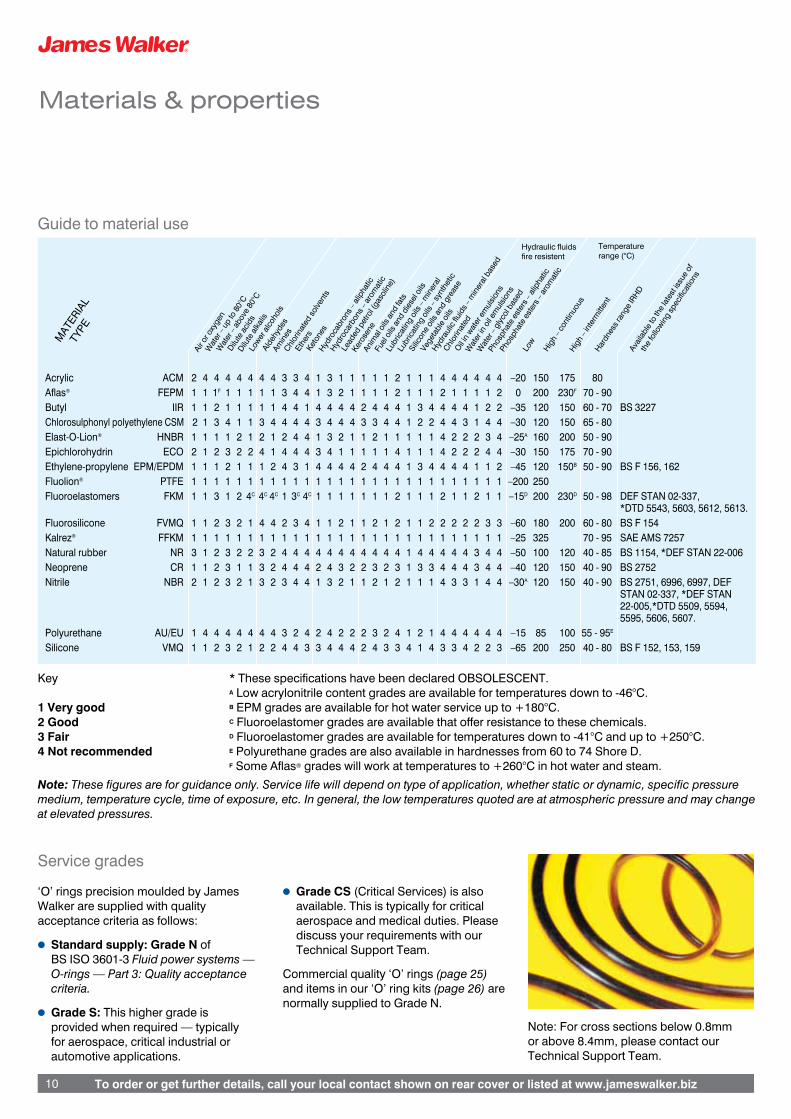
Guide to material use
Key * These specifications have been declared OBSOLESCENT. A Low acrylonitrile content grades are available for temperatures down to -46°C.1 Very good B EPM grades are available for hot water service up to +180°C.2 Good C Fluoroelastomer grades are available that offer resistance to these chemicals.3 Fair D Fluoroelastomer grades are available for temperatures down to -41°C and up to +250°C.4 Not recommended E Polyurethane grades are also available in hardnesses from 60 to 74 Shore D. F Some Aflas® grades will work at temperatures to +260°C in hot water and steam. Note: These figures are for guidance only. Service life will depend on type of application, whether static or dynamic, specific pressure medium, temperature cycle, time of exposure, etc. In general, the low temperatures quoted are at atmospheric pressure and may change at elevated pressures.
Acrylic ACM 2 4 4 4 4 4 4 4 3 3 4 1 3 1 1 1 1 1 2 1 1 1 4 4 4 4 4 4 –20 150 175 80Aflas® FEPM 1 1 1F 1 1 1 1 1 3 4 4 1 3 2 1 1 1 1 2 1 1 1 2 1 1 1 1 2 0 200 230F 70 - 90Butyl IIR 1 1 2 1 1 1 1 1 4 4 1 4 4 4 4 2 4 4 4 1 3 4 4 4 4 1 2 2 –35 120 150 60 - 70 BS 3227Chlorosulphonyl polyethylene CSM 2 1 3 4 1 1 3 4 4 4 4 3 4 4 4 3 3 4 4 1 2 2 4 4 3 1 4 4 –30 120 150 65 - 80Elast-O-Lion® HNBR 1 1 1 1 2 1 2 1 2 4 4 1 3 2 1 1 2 1 1 1 1 1 4 2 2 2 3 4 –25A 160 200 50 - 90Epichlorohydrin ECO 2 1 2 3 2 2 4 1 4 4 4 3 4 1 1 1 1 1 4 1 1 1 4 2 2 2 4 4 –30 150 175 70 - 90Ethylene-propylene EPM/EPDM 1 1 1 2 1 1 1 2 4 3 1 4 4 4 4 2 4 4 4 1 3 4 4 4 4 1 1 2 –45 120 150B 50 - 90 BS F 156, 162 Fluolion® PTFE 1 1 1 1 1 1 1 1 1 1 1 1 1 1 1 1 1 1 1 1 1 1 1 1 1 1 1 1 –200 250Fluoroelastomers FKM 1 1 3 1 2 4C 4C 4C 1 3C 4C 1 1 1 1 1 1 1 2 1 1 1 2 1 1 2 1 1 –15D 200 230D 50 - 98 DEF STAN 02-337, *DTD 5543, 5603, 5612, 5613.Fluorosilicone FVMQ 1 1 2 3 2 1 4 4 2 3 4 1 1 2 1 1 2 1 2 1 1 2 2 2 2 2 3 3 –60 180 200 60 - 80 BS F 154Kalrez® FFKM 1 1 1 1 1 1 1 1 1 1 1 1 1 1 1 1 1 1 1 1 1 1 1 1 1 1 1 1 –25 325 70 - 95 SAE AMS 7257Natural rubber NR 3 1 2 3 2 2 3 2 4 4 4 4 4 4 4 4 4 4 4 1 4 4 4 4 4 3 4 4 –50 100 120 40 - 85 BS 1154, *DEF STAN 22-006Neoprene CR 1 1 2 3 1 1 3 2 4 4 4 2 4 3 2 2 3 2 3 1 3 3 4 4 4 3 4 4 –40 120 150 40 - 90 BS 2752Nitrile NBR 2 1 2 3 2 1 3 2 3 4 4 1 3 2 1 1 2 1 2 1 1 1 4 3 3 1 4 4 –30A 120 150 40 - 90 BS 2751, 6996, 6997, DEF STAN 02-337, *DEF STAN 22-005,*DTD 5509, 5594, 5595, 5606, 5607.Polyurethane AU/EU 1 4 4 4 4 4 4 4 3 2 4 2 4 2 2 2 3 2 4 1 2 1 4 4 4 4 4 4 –15 85 100 55 - 95E
Silicone VMQ 1 1 2 3 2 1 2 2 4 4 3 3 4 4 4 2 4 3 3 4 1 4 3 3 4 2 2 3 –65 200 250 40 - 80 BS F 152, 153, 159
MAT
ERIA
L
TYPE
Air o
r oxy
gen
Wat
er –
up
to 8
0°C
Wat
er –
abo
ve 8
0°C
Dilu
te a
cids
Dilu
te a
lkal
is
Lower
alc
ohol
s
Alde
hyde
sAm
ines
Chlo
rinat
ed s
olve
nts
Ethe
rsKe
tone
sHyd
roca
bron
s –
alip
hatic
Hydro
carb
ons
– ar
omat
ic
Lead
ed p
etro
l (ga
solin
e)
Kero
sene
Anim
al o
ils a
nd fa
ts
Fuel
oils
and
die
sel o
ils
Lubr
icat
ing
oils
– m
iner
al
Lubr
icat
ing
oils
– sy
nthe
tic
Silic
one
oils
and
grea
se
Vege
tabl
e oi
ls
Hydra
ulic
flui
ds –
min
eral
bas
ed
Chlo
rinat
edO
il in
water
em
ulsio
ns
Wat
er in
oil e
mul
sions
Wat
er –
gly
col b
ased
Phos
phat
e es
ters
– a
lipha
tic
Phos
phat
e es
ters
– a
rom
atic
Low
High
– co
ntin
uous
High
– in
term
itten
tHar
dnes
s ra
nge
IRHD
Avai
labl
e to
the
late
st is
sue
of
the
follo
wing
spec
ificat
ions
Temperaturerange (°C)
Hydraulic fluidsfire resistent
Service grades
‘O’ rings precision moulded by James Walker are supplied with quality acceptance criteria as follows:
l Standard supply: Grade N of BS ISO 3601-3 Fluid power systems — O-rings — Part 3: Quality acceptance criteria.
l Grade S: This higher grade is provided when required — typically for aerospace, critical industrial or automotive applications.
l Grade CS (Critical Services) is also available. This is typically for critical aerospace and medical duties. Please discuss your requirements with our Technical Support Team.
Commercial quality ‘O’ rings (page 25) and items in our ‘O’ ring kits (page 26) are normally supplied to Grade N.
Note: For cross sections below 0.8mm or above 8.4mm, please contact our Technical Support Team.

To order or get further details, call your local contact shown on rear cover or listed at www.jameswalker.biz 11
Materials & properties
Rapid gas decompression
Although rapid gas decompression (RGD) — previously known as explosive decompression (ED) — is a phenomenon generally found in the oil and gas industry, it can occur in any application where there is a rapid drop in gas pressure. Such damage is found in sealing applications ranging from paint guns and fire extinguishers to marine stern glands and systems containing refrigerants.
How damage occursRGD damage is structural failure in the forms of blistering, internal cracking and splits, caused when the gas pressure, to which a seal is exposed, rapidly reduces from high to low. Although no strict rules apply, damage should be considered in a gas or dissolved gas system when pressure is greater than 5MPa (725psi), and decompression exceeds 1MPa (145psi) per hour.
The elastomeric parts in a system are, to a greater or lesser degree, susceptible to the permeation and diffusion of gases dissolving in their surface. In time, the elastomer becomes saturated with gases.
Under these conditions — as long as the gas pressure in the elastomer remains at equilibrium with the ambient pressure — there is minimal, if any, damage. Thus, no deterioration in performance of the elastomeric part occurs (unless caused by other factors, eg chemical or thermal degradation or extrusion damage).
When external gas pressure is removed or pressure fluctuations occur, large pressure gradients are created between the interior and surface of the component. This pressure differential may be balanced by the gas diffusing /permeating out of the elastomer, especially if any external constraints are not removed.
But, if the elastomer cannot resist crack or blister growth during the permeation process, then structural failure will result.
Rapid gas decompression damage can manifest itself in various ways — anything from internal splits that are not visible on the surface of the seal, to surface blisters, fractures and complete fragmentation.
Leader in RGD-resistant elastomersWe have conducted intensive materials development programmes over the past 30 years to help industry overcome RGD problems. Much of this work is carried out in collaboration with plant manufacturers, oil/gas operators and research bodies.
We offer RGD resistant elastomers, which are validated by James Walker Technology Centre. Specific grades are tested and approved by oilfield operators and equipment manufacturers, with several qualified to Norsok M-710 Annex B.
The formulation, mixing, quality control and processing of these compounds is rigorously controlled. Today they are rated as benchmarks by which others are judged. Albeit each compound has a broad range of applications capability, their particular features are as follows:
l FR68/90 — this fluorocarbon-basedmaterial is the first in our new generation of oil and gas elastomers. With new polymer architecture, it offers low compression set, excellent RGD resistance, plus enhanced resistance to sour gas, amines and steam. It is Norsok rated up to at least 8.4mm cross section ‘O’ rings.
l FR58/90 — fluorocarbon terpolymer (FKM) material with excellent chemical and thermal properties, plus good RGD resistance. It is widely approved and
specified for oilfield duties, and has also achieved the highest Norsok rating of 0000 with 5.33mm section ‘O’ rings.
l FR25/90 — a fluorocarbon tetrapolymer (FKM) that combines improved low temperature capability with excellent chemical properties. It offers excellent RGD resistance, and has achieved the highest Norsok rating of 0000 with 6.99mm and 5.33mm section ‘O’ rings.
l Elast-O-Lion® 101 — an hydrogenated nitrile (HNBR) grade with high mechanical strength and wear resistance. It has good resistance to many oilfield chemicals, including H2S and amine corrosion inhibitors. It is resistant to RGD and approved to many oilfield specifications. It achieved the highest Norsok rating of 0000 with 6.99mm section ‘O’ rings.
l Elast-O-Lion® 985 — our hydrogenated nitrile (HNBR) grade with a temperature capability down to -55°C, but offering reduced mechanical properties and RGD resistance when compared to Elast-O-Lion 101.
l AF69/90 — An Aflas® (FEPM) based RGD-resistant grade with excellent resistance to oilfield media and steam.
For detailed information on RGD-resistant grades see: Elastomeric seals & components for the Oil & Gas Industry.
James Walker’s RGD materials test laboratory
To order or get further details, call your local contact shown on rear cover or listed at www.jameswalker.biz12
Materials & properties
FEP encapsulated ‘O’ rings
These have a core of elastomer that is completely covered with a seamless sheath of fluorinated ethylene propylene (FEP). The core is normally fluorocarbon (FKM) or silicone (VMQ).
Encapsulated ‘O’ rings are generally used when:
l A standard elastomeric ‘O’ ring has inadequate chemical resistance for a specific application, and
l A solid PTFE ‘O’ ring does not offer sufficient elasticity for reliable, long-term fluid sealing.
They are used where high levels of chemical resistance or hygiene are needed — typically in petrochemical, chemical, food or pharmaceutical plant.
Although FEP encapsulated ‘O’ rings are most suited to static duties, they may be used with slow short movements on rotary applications such as valve stem sealing.
Their advantages are manifold, including:
l Excellent chemical resistance to a wide range of media. Please contact our Technical Support Team for details.
l Operational temperature ranges of:-60°C to +200°C with silicone core. -20°C to +200°C with fluorocarbon core.
l Low friction and low ‘stick-slip’ effect.l Far greater elasticity than solid PTFE.
Our FEP encapsulated ‘O’ rings are fully interchangeable with standard ‘O’ rings.
However, due to the FEP sheath, they are less flexible than elastomeric rings and have limited stretch with higher permanent deformation. Auxiliary tools may be needed to facilitate efficient fitting.
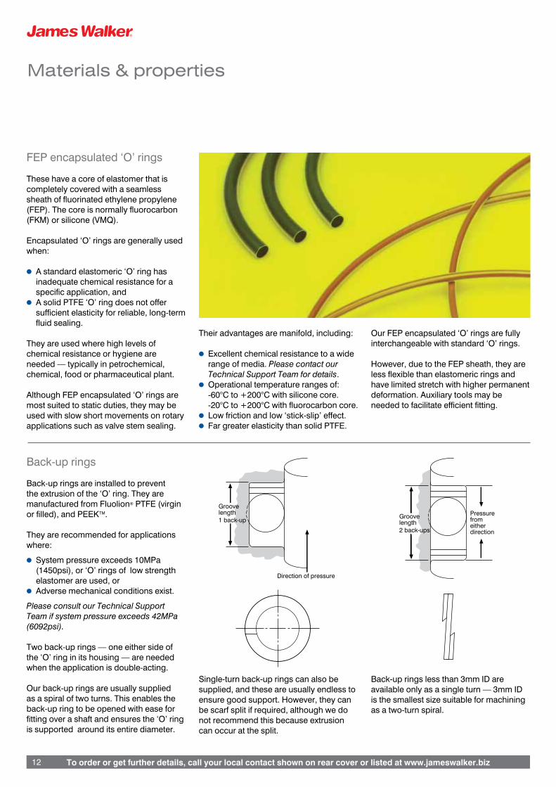
Back-up rings
Back-up rings are installed to prevent the extrusion of the ‘O’ ring. They are manufactured from Fluolion® PTFE (virgin or filled), and PEEKTM.
They are recommended for applications where:
l System pressure exceeds 10MPa (1450psi), or ‘O’ rings of low strength elastomer are used, or
l Adverse mechanical conditions exist.
Please consult our Technical Support Team if system pressure exceeds 42MPa (6092psi).
Two back-up rings — one either side of the ‘O’ ring in its housing — are needed when the application is double-acting.
Our back-up rings are usually supplied as a spiral of two turns. This enables the back-up ring to be opened with ease for fitting over a shaft and ensures the ‘O’ ring is supported around its entire diameter.
Single-turn back-up rings can also be supplied, and these are usually endless to ensure good support. However, they can be scarf split if required, although we do not recommend this because extrusion can occur at the split.
Groovelength1 back-up
Direction of pressure
Groovelength2 back-ups
Pressurefromeitherdirection
Groovelength1 back-up
Direction of pressure
Groovelength2 back-ups
Pressurefromeitherdirection
Groovelength1 back-up
Direction of pressure
Groovelength2 back-ups
Pressurefromeitherdirection
Groovelength1 back-up
Direction of pressure
Groovelength2 back-ups
Pressurefromeitherdirection
Back-up rings less than 3mm ID are available only as a single turn — 3mm ID is the smallest size suitable for machining as a two-turn spiral.
To order or get further details, call your local contact shown on rear cover or listed at www.jameswalker.biz 13
Header
To order or get further details, call your local contact shown on rear cover or listed at www.jameswalker.biz 13
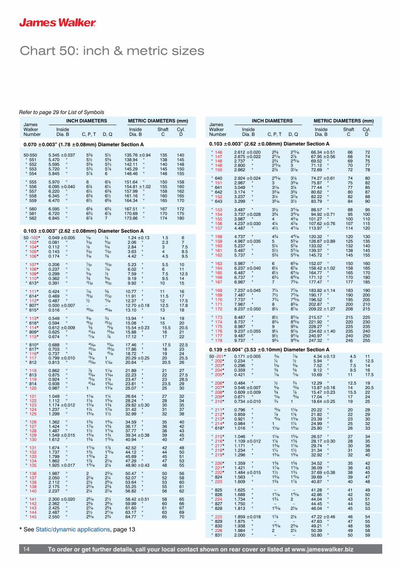
Chart 50: inch & metric sizes
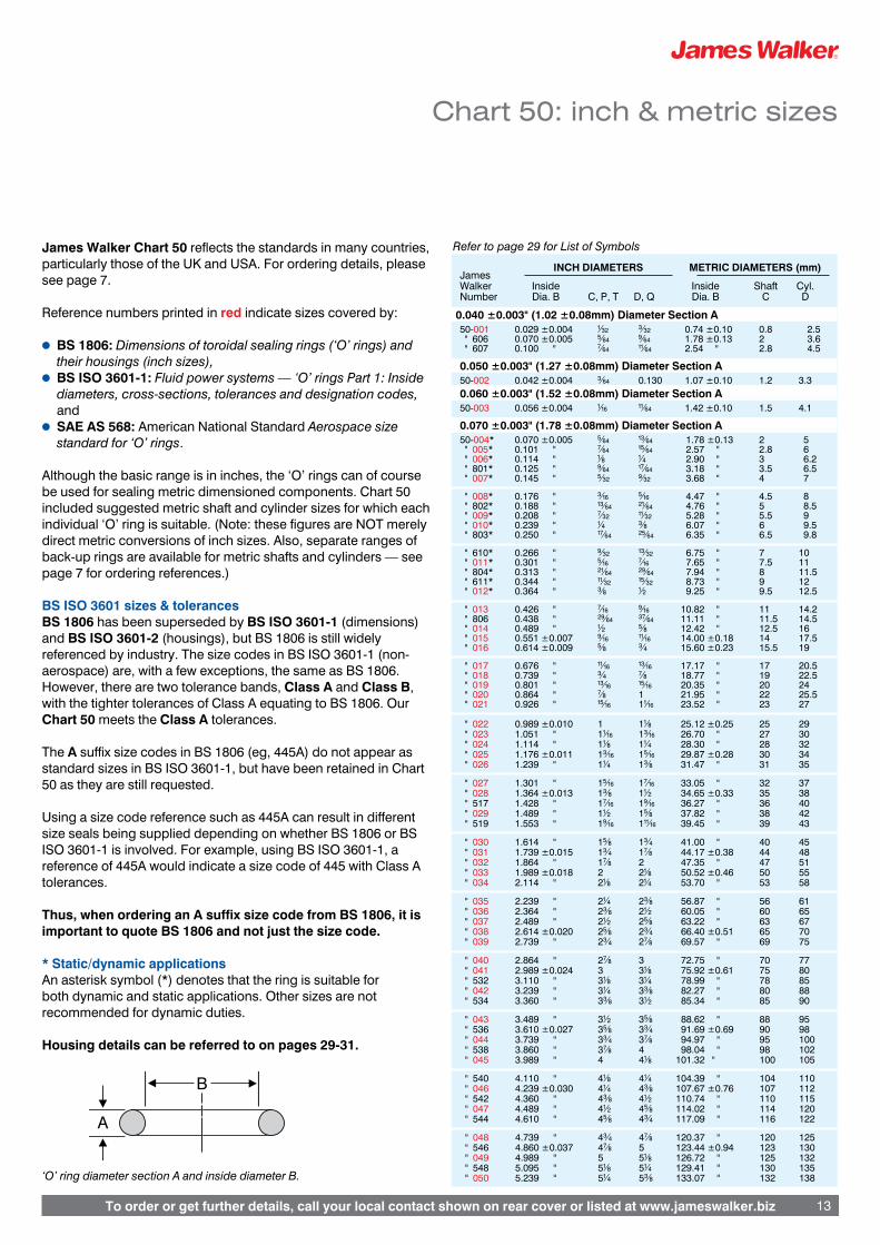
James Walker Chart 50 reflects the standards in many countries, particularly those of the UK and USA. For ordering details, please see page 7.
Reference numbers printed in red indicate sizes covered by:
l BS 1806: Dimensions of toroidal sealing rings (‘O’ rings) and their housings (inch sizes),
l BS ISO 3601-1: Fluid power systems — ‘O’ rings Part 1: Inside diameters, cross-sections, tolerances and designation codes, and
l SAE AS 568: American National Standard Aerospace size standard for ‘O’ rings.
Although the basic range is in inches, the ‘O’ rings can of course be used for sealing metric dimensioned components. Chart 50 included suggested metric shaft and cylinder sizes for which each individual ‘O’ ring is suitable. (Note: these figures are NOT merely direct metric conversions of inch sizes. Also, separate ranges of back-up rings are available for metric shafts and cylinders — see page 7 for ordering references.)
BS ISO 3601 sizes & tolerancesBS 1806 has been superseded by BS ISO 3601-1 (dimensions) and BS ISO 3601-2 (housings), but BS 1806 is still widely referenced by industry. The size codes in BS ISO 3601-1 (non-aerospace) are, with a few exceptions, the same as BS 1806. However, there are two tolerance bands, Class A and Class B, with the tighter tolerances of Class A equating to BS 1806. Our Chart 50 meets the Class A tolerances.
The A suffix size codes in BS 1806 (eg, 445A) do not appear as standard sizes in BS ISO 3601-1, but have been retained in Chart 50 as they are still requested.
Using a size code reference such as 445A can result in different size seals being supplied depending on whether BS 1806 or BS ISO 3601-1 is involved. For example, using BS ISO 3601-1, a reference of 445A would indicate a size code of 445 with Class A tolerances.
Thus, when ordering an A suffix size code from BS 1806, it is important to quote BS 1806 and not just the size code.
* Static/dynamic applicationsAn asterisk symbol (*) denotes that the ring is suitable for both dynamic and static applications. Other sizes are not recommended for dynamic duties.
Housing details can be referred to on pages 29-31.
‘O’ ring diameter section A and inside diameter B.
A
B
INCH DIAMETERS METRIC DIAMETERS (mm) James Walker Inside Inside Shaft Cyl. Number Dia. B C, P, T D, Q Dia. B C D
0.040 ±0.003" (1.02 ±0.08mm) Diameter Section A 50-001 0.029 ±0.004 ⁄÷#™ ‹÷#™ 0.74 ±0.10 0.8 2.5 " 606 0.070 ±0.005 fi÷§¢ ·÷§¢ 1.78 ±0.13 2 3.6 " 607 0.100 " ‡÷§¢ ⁄⁄÷§¢ 2.54 " 2.8 4.5
0.050 ±0.003" (1.27 ±0.08mm) Diameter Section A 50-002 0.042 ±0.004 ‹÷§¢ 0.130 1.07 ±0.10 1.2 3.3
0.060 ±0.003" (1.52 ±0.08mm) Diameter Section A 50-003 0.056 ±0.004 ⁄÷¡§ ⁄⁄÷§¢ 1.42 ±0.10 1.5 4.1
0.070 ±0.003" (1.78 ±0.08mm) Diameter Section A 50-004* 0.070 ±0.005 fi÷§¢ ⁄‹÷§¢ 1.78 ±0.13 2 5 " 005* 0.101 " ‡÷§¢ ⁄fi÷§¢ 2.57 " 2.8 6 " 006* 0.114 " ⁄÷• ⁄÷¢ 2.90 " 3 6.2 " 801* 0.125 " ·÷§¢ ⁄‡÷§¢ 3.18 " 3.5 6.5 " 007* 0.145 " fi÷#™ ·÷#™ 3.68 " 4 7
" 008* 0.176 " ‹÷¡§ fi÷¡§ 4.47 " 4.5 8 " 802* 0.188 " ⁄‹÷§¢ ¤⁄÷§¢ 4.76 " 5 8.5 " 009* 0.208 " ‡÷#™ ⁄⁄÷#™ 5.28 " 5.5 9 " 010* 0.239 " ⁄÷¢ ‹÷• 6.07 " 6 9.5 " 803* 0.250 " ⁄‡÷§¢ ¤fi÷§¢ 6.35 " 6.5 9.8
" 610* 0.266 " ·÷#™ ⁄‹÷#™ 6.75 " 7 10 " 011* 0.301 " fi÷¡§ ‡÷¡§ 7.65 " 7.5 11 " 804* 0.313 " ¤⁄÷§¢ ¤·÷§¢ 7.94 " 8 11.5 " 611* 0.344 " ⁄⁄÷#™ ⁄fi÷#™ 8.73 " 9 12 " 012* 0.364 " ‹÷• ⁄÷™ 9.25 " 9.5 12.5
" 013 0.426 " ‡÷¡§ ·÷¡§ 10.82 " 11 14.2 " 806 0.438 " ¤·÷§¢ ‹‡÷§¢ 11.11 " 11.5 14.5 " 014 0.489 " ⁄÷™ fi÷• 12.42 " 12.5 16 " 015 0.551 ±0.007 ·÷¡§ ⁄⁄÷¡§ 14.00 ±0.18 14 17.5 " 016 0.614 ±0.009 fi÷• ‹÷¢ 15.60 ±0.23 15.5 19
" 017 0.676 " ⁄⁄÷¡§ ⁄‹÷¡§ 17.17 " 17 20.5 " 018 0.739 " ‹÷¢ ‡÷• 18.77 " 19 22.5 " 019 0.801 " ⁄‹÷¡§ ⁄fi÷¡§ 20.35 " 20 24 " 020 0.864 " ‡÷• 1 21.95 " 22 25.5 " 021 0.926 " ⁄fi÷¡§ 1⁄÷¡§ 23.52 " 23 27 " 022 0.989 ±0.010 1 1⁄÷• 25.12 ±0.25 25 29 " 023 1.051 " 1⁄÷¡§ 1‹÷¡§ 26.70 " 27 30 " 024 1.114 " 1⁄÷• 1⁄÷¢ 28.30 " 28 32 " 025 1.176 ±0.011 1‹÷¡§ 1fi÷¡§ 29.87 ±0.28 30 34 " 026 1.239 " 1⁄÷¢ 1‹÷• 31.47 " 31 35
" 027 1.301 " 1fi÷¡§ 1‡÷¡§ 33.05 " 32 37 " 028 1.364 ±0.013 1‹÷• 1⁄÷™ 34.65 ±0.33 35 38 " 517 1.428 " 1‡÷¡§ 1·÷¡§ 36.27 " 36 40 " 029 1.489 " 1⁄÷™ 1fi÷• 37.82 " 38 42 " 519 1.553 " 1·÷¡§ 1⁄⁄÷¡§ 39.45 " 39 43
" 030 1.614 " 1fi÷• 1‹÷¢ 41.00 " 40 45 " 031 1.739 ±0.015 1‹÷¢ 1‡÷• 44.17 ±0.38 44 48 " 032 1.864 " 1‡÷• 2 47.35 " 47 51 " 033 1.989 ±0.018 2 2⁄÷• 50.52 ±0.46 50 55 " 034 2.114 " 2⁄÷• 2⁄÷¢ 53.70 " 53 58
" 035 2.239 " 2⁄÷¢ 2‹÷• 56.87 " 56 61 " 036 2.364 " 2‹÷• 2⁄÷™ 60.05 " 60 65 " 037 2.489 " 2⁄÷™ 2fi÷• 63.22 " 63 67 " 038 2.614 ±0.020 2fi÷• 2‹÷¢ 66.40 ±0.51 65 70 " 039 2.739 " 2‹÷¢ 2‡÷• 69.57 " 69 75
" 040 2.864 " 2‡÷• 3 72.75 " 70 77 " 041 2.989 ±0.024 3 3⁄÷• 75.92 ±0.61 75 80 " 532 3.110 " 3⁄÷• 3⁄÷¢ 78.99 " 78 85 " 042 3.239 " 3⁄÷¢ 3‹÷• 82.27 " 80 88 " 534 3.360 " 3‹÷• 3⁄÷™ 85.34 " 85 90
" 043 3.489 " 3⁄÷™ 3fi÷• 88.62 " 88 95 " 536 3.610 ±0.027 3fi÷• 3‹÷¢ 91.69 ±0.69 90 98 " 044 3.739 " 3‹÷¢ 3‡÷• 94.97 " 95 100 " 538 3.860 " 3‡÷• 4 98.04 " 98 102 " 045 3.989 " 4 4⁄÷• 101.32 " 100 105
" 540 4.110 " 4⁄÷• 4⁄÷¢ 104.39 " 104 110 " 046 4.239 ±0.030 4⁄÷¢ 4‹÷• 107.67 ±0.76 107 112 " 542 4.360 " 4‹÷• 4⁄÷™ 110.74 " 110 115 " 047 4.489 " 4⁄÷™ 4fi÷• 114.02 " 114 120 " 544 4.610 " 4fi÷• 4‹÷¢ 117.09 " 116 122
" 048 4.739 " 4‹÷¢ 4‡÷• 120.37 " 120 125 " 546 4.860 ±0.037 4‡÷• 5 123.44 ±0.94 123 130 " 049 4.989 " 5 5⁄÷• 126.72 " 125 132 " 548 5.095 " 5⁄÷• 5⁄÷¢ 129.41 " 130 135 " 050 5.239 " 5⁄÷¢ 5‹÷• 133.07 " 132 138
Refer to page 29 for List of Symbols
To order or get further details, call your local contact shown on rear cover or listed at www.jameswalker.biz14
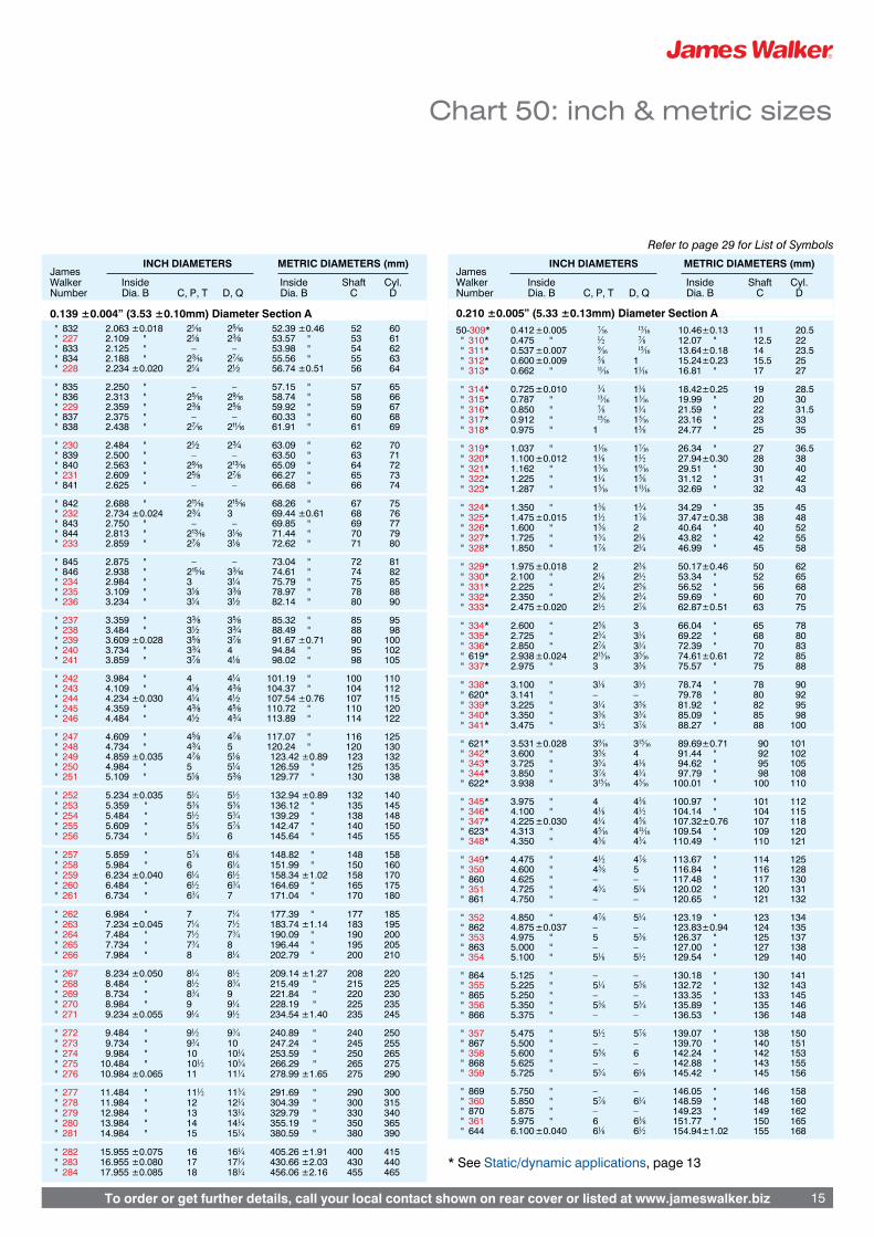
Chart 50: inch & metric sizes
* See Static/dynamic applications, page 13
INCH DIAMETERS METRIC DIAMETERS (mm) James Walker Inside Inside Shaft Cyl. Number Dia. B C, P, T D, Q Dia. B C D
0.070 ±0.003” (1.78 ±0.08mm) Diameter Section A
50-550 5.345 ±0.037 5‹÷• 5⁄÷™ 135.76 ±0.94 135 140 " 551 5.470 " 5⁄÷™ 5fi÷• 138.94 " 138 145 " 552 5.595 " 5fi÷• 5‹÷¢ 142.11 " 140 148 " 553 5.720 " 5‹÷¢ 5‡÷• 145.29 " 145 150 " 554 5.845 " 5‡÷• 6 148.46 " 148 155
" 555 5.970 " 6 6⁄÷• 151.64 " 150 158 " 556 6.095 ±0.040 6⁄÷• 6⁄÷¢ 154.81 ±1.02 155 160 " 557 6.220 " 6⁄÷¢ 6‹÷• 157.99 " 158 162 " 558 6.345 " 6‹÷• 6⁄÷™ 161.16 " 160 165 " 559 6.470 " 6⁄÷™ 6fi÷• 164.34 " 165 170
" 560 6.595 " 6fi÷• 6‹÷¢ 167.51 " 167 172 " 561 6.720 " 6‹÷¢ 6‡÷• 170.69 " 170 175 " 562 6.845 " 6‡÷• 7 173.86 " 174 180
0.103 ±0.003” (2.62 ±0.08mm) Diameter Section A 50 -102* 0.049 ±0.005 ⁄÷¡§ ⁄÷¢ 1.24 ±0.13 1.5 6 " 103* 0.081 " ‹÷#™ ·÷#™ 2.06 " 2.3 7 " 104* 0.112 " ⁄÷• fi÷¡§ 2.84 " 3 7.5 " 105* 0.143 " fi÷#™ ⁄⁄÷#™ 3.63 " 4 8.5 " 106* 0.174 " ‹÷¡§ ‹÷• 4.42 " 4.5 9.5
" 107* 0.206 " ‡÷#™ ⁄‹÷#™ 5.23 " 5.5 10 " 108* 0.237 " ⁄÷¢ ‡÷¡§ 6.02 " 6 11 " 109* 0.299 " fi÷¡§ ⁄÷™ 7.59 " 7.5 12.5 " 110* 0.362 " ‹÷• ·÷¡§ 9.19 " 9.5 14 " 613* 0.391 " ⁄‹÷#™ ⁄·÷#™ 9.92 " 10 15
" 111* 0.424 " ‡÷¡§ fi÷• 10.77 " 11 16 " 614* 0.469 " ⁄fi÷#™ ¤⁄÷#™ 11.91 " 11.5 17 " 112* 0.487 " ⁄÷™ ⁄⁄÷¡§ 12.37 " 12 17.5 " 807* 0.500 ±0.007 – – 12.70 ±0.18 12.5 17.8 " 615* 0.516 " ‹‹÷§¢ ›fi÷§¢ 13.10 " 13 18
" 113* 0.549 " ·÷¡§ ‹÷¢ 13.94 " 14 19 " 616* 0.594 " ⁄·÷#™ ¤fi÷#™ 15.08 " 15 20 " 114* 0.612 ±0.009 fi÷• ⁄‹÷¡§ 15.54 ±0.23 15.5 20.5 " 809* 0.625 " ›⁄÷§¢ fi‹÷§¢ 15.88 " 16 21 " 115* 0.674 " ⁄⁄÷¡§ ‡÷• 17.12 " 17 22
" 810* 0.688 " ›fi÷§¢ fi‡÷§¢ 17.46 " 17.5 22.5 " 617* 0.703 " ¤‹÷#™ ¤·÷#™ 17.86 " 18 23 " 116* 0.737 " ‹÷¢ ⁄fi÷¡§ 18.72 " 19 24 " 117 0.799 ±0.010 ⁄‹÷¡§ 1 20.29 ±0.25 20 25.5 " 812 0.813 " fi‹÷§¢ 1⁄÷§¢ 20.64 " 20.5 26
" 118 0.862 " ‡÷• 1⁄÷¡§ 21.89 " 21 27 " 813 0.875 " fi‡÷§¢ 1fi÷§¢ 22.23 " 22 27.5 " 119 0.924 " ⁄fi÷¡§ 1⁄÷• 23.47 " 23 28.5 " 814 0.938 " fl⁄÷§¢ 1·÷§¢ 23.81 " 23.5 29 " 120 0.987 " 1 1‹÷¡§ 25.07 " 25 30
" 121 1.049 " 1⁄÷¡§ 1⁄÷¢ 26.64 " 27 32 " 122 1.112 " 1⁄÷• 1fi÷¡§ 28.24 " 28 34 " 123 1.174 ±0.012 1‹÷¡§ 1‹÷• 29.82 ±0.30 30 35 " 124 1.237 " 1⁄÷¢ 1‡÷¡§ 31.42 " 31 37 " 125 1.299 " 1fi÷¡§ 1⁄÷™ 32.99 " 32 38
" 126 1.362 " 1‹÷• 1·÷¡§ 34.59 " 35 40 " 127 1.424 " 1‡÷¡§ 1fi÷• 36.17 " 36 42 " 128 1.487 " 1⁄÷™ 1⁄⁄÷¡§ 37.77 " 38 43 " 129 1.549 ±0.015 1·÷¡§ 1‹÷¢ 39.34 ±0.38 39 45 " 130 1.612 " 1fi÷• 1⁄‹÷¡§ 40.94 " 40 47
" 131 1.674 " 1⁄⁄÷¡§ 1‡÷• 42.52 " 42 48 " 132 1.737 " 1‹÷¢ 1⁄fi÷¡§ 44.12 " 44 50 " 133 1.799 " 1⁄‹÷¡§ 2 45.69 " 45 51 " 134 1.862 " 1‡÷• 2⁄÷¡§ 47.29 " 47 53 " 135 1.925 ±0.017 1⁄fi÷¡§ 2⁄÷• 48.90 ±0.43 48 55
" 136 1.987 " 2 2‹÷¡§ 50.47 " 50 56 " 137 2.050 " 2⁄÷¡§ 2⁄÷¢ 52.07 " 52 58 " 138 2.112 " 2⁄÷• 2fi÷¡§ 53.64 " 53 60 " 139 2.175 " 2‹÷¡§ 2‹÷• 55.25 " 55 61 " 140 2.237 " 2⁄÷¢ 2‡÷¡§ 56.82 " 56 62
" 141 2.300 ±0.020 2fi÷¡§ 2⁄÷™ 58.42 ±0.51 58 65 " 142 2.362 " 2‹÷• 2·÷¡§ 59.99 " 60 66 " 143 2.425 " 2‡÷¡§ 2fi÷• 61.60 " 61 67 " 144 2.487 " 2⁄÷™ 2⁄⁄÷¡§ 63.17 " 63 69 " 145 2.550 " 2·÷¡§ 2‹÷¢ 64.77 " 65 70
INCH DIAMETERS METRIC DIAMETERS (mm) James Walker Inside Inside Shaft Cyl. Number Dia. B C, P, T D, Q Dia. B C D
0.103 ±0.003” (2.62 ±0.08mm) Diameter Section A
" 146 2.612 ±0.020 2fi÷• 2⁄‹÷¡§ 66.34 ±0.51 66 72 " 147 2.675 ±0.022 2⁄⁄÷¡§ 2‡÷• 67.95 ±0.56 68 74 " 148 2.737 " 2‹÷¢ 2⁄fi÷¡§ 69.52 " 69 75 " 149 2.800 " 2⁄‹÷¡§ 3 71.12 " 70 77 " 150 2.862 " 2‡÷• 3⁄÷¡§ 72.69 " 72 78
" 640 2.924 ±0.024 2⁄fi÷¡§ 3⁄÷• 74.27 ±0.61 74 80 " 151 2.987 " 3 3‹÷¡§ 75.87 " 75 82 " 641 3.049 " 3⁄÷¡§ 3⁄÷¢ 77.44 " 77 85 " 642 3.174 " 3‹÷¡§ 3‹÷• 80.62 " 80 87 " 152 3.237 " 3⁄÷¢ 3‡÷¡§ 82.22 " 82 88 " 643 3.299 " 3fi÷¡§ 3⁄÷™ 83.79 " 84 90
" 153 3.487 " 3⁄÷™ 3⁄⁄÷¡§ 88.57 " 88 95 " 154 3.737 ±0.028 3‹÷¢ 3⁄fi÷¡§ 94.92 ±0.71 95 100 " 155 3.987 " 4 4‹÷¡§ 101.27 " 100 110 " 156 4.237 ±0.030 4⁄÷¢ 4‡÷¡§ 107.62 ±0.76 107 115 " 157 4.487 " 4⁄÷™ 4⁄⁄÷¡§ 113.97 " 114 120
" 158 4.737 " 4‹÷¢ 4⁄fi÷¡§ 120.32 " 120 130 " 159 4.987 ±0.035 5 5‹÷¡§ 126.67 ±0.89 125 135 " 160 5.237 " 5⁄÷¢ 5‡÷¡§ 133.02 " 132 140 " 161 5.487 " 5⁄÷™ 5⁄⁄÷¡§ 139.37 " 138 145 " 162 5.737 " 5‹÷¢ 5⁄fi÷¡§ 145.72 " 145 155
" 163 5.987 " 6 6‹÷¡§ 152.07 " 150 160 " 164 6.237 ±0.040 6⁄÷¢ 6‡÷¡§ 158.42 ±1.02 158 165 " 165 6.487 " 6⁄÷™ 6⁄⁄÷¡§ 164.77 " 165 170 " 166 6.737 " 6‹÷¢ 6⁄fi÷¡§ 171.12 " 170 180 " 167 6.987 " 7 7‹÷¡§ 177.47 " 177 185
" 168 7.237 ±0.045 7⁄÷¢ 7‡÷¡§ 183.82 ±1.14 183 190 " 169 7.487 " 7⁄÷™ 7⁄⁄÷¡§ 190.17 " 190 200 " 170 7.737 " 7‹÷¢ 7⁄fi÷¡§ 196.52 " 195 205 " 171 7.987 " 8 8‹÷¡§ 202.87 " 200 210 " 172 8.237 ±0.050 8⁄÷¢ 8‡÷¡§ 209.22 ±1.27 208 215
" 173 8.487 " 8⁄÷™ 8⁄⁄÷¡§ 215.57 " 215 225 " 174 8.737 " 8‹÷¢ 8⁄fi÷¡§ 221.92 " 220 230 " 175 8.987 " 9 9‹÷¡§ 228.27 " 225 235 " 176 9.237 ±0.055 9⁄÷¢ 9‡÷¡§ 234.62 ±1.40 235 240 " 177 9.487 " 9⁄÷™ 9⁄⁄÷¡§ 240.97 " 240 250 " 178 9.737 " 9‹÷¢ 9⁄fi÷¡§ 247.32 " 245 255
0.139 ±0.004” (3.53 ±0.10mm) Diameter Section A 50 -201* 0.171 ±0.005 ‹÷¡§ ‡÷¡§ 4.34 ±0.13 4.5 11 " 202* 0.234 " ⁄÷¢ ⁄÷™ 5.94 " 6 12.5 " 203* 0.296 " fi÷¡§ ·÷¡§ 7.52 " 7.5 14 " 204* 0.359 " ‹÷• fi÷• 9.12 " 9.5 16 " 205* 0.421 " ‡÷¡§ ⁄⁄÷¡§ 10.69 " 11 17.5
" 206* 0.484 " ⁄÷™ ‹÷¢ 12.29 " 12.5 19 " 207* 0.546 ±0.007 ·÷¡§ ⁄‹÷¡§ 13.87 ±0.18 14 20.5 " 208* 0.609 ±0.009 fi÷• ‡÷• 15.47 ±0.23 15.5 22 " 209* 0.671 " ⁄⁄÷¡§ ⁄fi÷¡§ 17.04 " 17 24 " 210* 0.734 ±0.010 ‹÷¢ 1 18.64 ±0.25 19 25
" 211* 0.796 " ⁄‹÷¡§ 1⁄÷¡§ 20.22 " 20 28 " 212* 0.859 " ‡÷• 1⁄÷• 21.82 " 22 29 " 213* 0.921 " ⁄fi÷¡§ 1‹÷¡§ 23.39 " 23 30 " 214* 0.984 " 1 1⁄÷¢ 24.99 " 25 32 " 618* 1.016 " 1⁄÷#™ 1·÷#™ 25.80 " 26 33
" 215* 1.046 " 1⁄÷¡§ 1fi÷¡§ 26.57 " 27 34 " 216* 1.109 ±0.012 1⁄÷• 1‹÷• 28.17 ±0.30 28 35 " 217* 1.171 " 1‹÷¡§ 1‡÷¡§ 29.74 " 30 36 " 218* 1.234 " 1⁄÷¢ 1⁄÷™ 31.34 " 31 38 " 219* 1.296 " 1fi÷¡§ 1·÷¡§ 32.92 " 32 40
" 220* 1.359 " 1‹÷• 1fi÷• 34.52 " 35 42 " 221* 1.421 " 1‡÷¡§ 1⁄⁄÷¡§ 36.09 " 36 43 " 222* 1.484 ±0.015 1⁄÷™ 1‹÷¢ 37.69 ±0.38 38 45 " 824 1.563 " 1·÷¡§ 1⁄‹÷¡§ 39.69 " 39 47 " 223 1.609 " 1fi÷• 1‡÷• 40.87 " 40 48
" 825 1.625 " – – 41.28 " 41 49 " 826 1.688 " 1⁄⁄÷¡§ 1⁄fi÷¡§ 42.86 " 42 50 " 224 1.734 " 1‹÷¢ 2 44.04 " 43 51 " 827 1.750 " – – 44.45 " 44 52 " 828 1.813 " 1⁄‹÷¡§ 2⁄÷¡§ 46.04 " 45 53
" 225 1.859 ±0.018 1‡÷• 2⁄÷• 47.22 ±0.46 46 54 " 829 1.875 " – – 47.63 " 47 55 " 830 1.938 " 1⁄fi÷¡§ 2‹÷¡§ 49.21 " 48 56 " 226 1.984 " 2 2⁄÷¢ 50.39 49 58 " 831 2.000 " – – 50.80 " 50 59
Refer to page 29 for List of Symbols
To order or get further details, call your local contact shown on rear cover or listed at www.jameswalker.biz 15
Chart 50: inch & metric sizes
INCH DIAMETERS METRIC DIAMETERS (mm) James Walker Inside Inside Shaft Cyl. Number Dia. B C, P, T D, Q Dia. B C D
0.139 ±0.004” (3.53 ±0.10mm) Diameter Section A " 832 2.063 ±0.018 2⁄÷¡§ 2fi÷¡§ 52.39 ±0.46 52 60 " 227 2.109 " 2⁄÷• 2‹÷• 53.57 " 53 61 " 833 2.125 " – – 53.98 " 54 62 " 834 2.188 " 2‹÷¡§ 2‡÷¡§ 55.56 " 55 63 " 228 2.234 ±0.020 2⁄÷¢ 2⁄÷™ 56.74 ±0.51 56 64
" 835 2.250 " – – 57.15 " 57 65 " 836 2.313 " 2fi÷¡§ 2·÷¡§ 58.74 " 58 66 " 229 2.359 " 2‹÷• 2fi÷• 59.92 " 59 67 " 837 2.375 " – – 60.33 " 60 68 " 838 2.438 " 2‡÷¡§ 2⁄⁄÷¡§ 61.91 " 61 69
" 230 2.484 " 2⁄÷™ 2‹÷¢ 63.09 " 62 70 " 839 2.500 " – – 63.50 " 63 71 " 840 2.563 " 2·÷¡§ 2⁄‹÷¡§ 65.09 " 64 72 " 231 2.609 " 2fi÷• 2‡÷• 66.27 " 65 73 " 841 2.625 " – – 66.68 " 66 74
" 842 2.688 " 2⁄⁄÷¡§ 2⁄fi÷¡§ 68.26 " 67 75 " 232 2.734 ±0.024 2‹÷¢ 3 69.44 ±0.61 68 76 " 843 2.750 " – – 69.85 " 69 77 " 844 2.813 " 2⁄‹÷¡§ 3⁄÷¡§ 71.44 " 70 79 " 233 2.859 " 2‡÷• 3⁄÷• 72.62 " 71 80
" 845 2.875 " – – 73.04 " 72 81 " 846 2.938 " 2⁄fi÷¡§ 3‹÷¡§ 74.61 " 74 82 " 234 2.984 " 3 3⁄÷¢ 75.79 " 75 85 " 235 3.109 " 3⁄÷• 3‹÷• 78.97 " 78 88 " 236 3.234 " 3⁄÷¢ 3⁄÷™ 82.14 " 80 90
" 237 3.359 " 3‹÷• 3fi÷• 85.32 " 85 95 " 238 3.484 " 3⁄÷™ 3‹÷¢ 88.49 " 88 98 " 239 3.609 ±0.028 3fi÷• 3‡÷• 91.67 ±0.71 90 100 " 240 3.734 " 3‹÷¢ 4 94.84 " 95 102 " 241 3.859 " 3‡÷• 4⁄÷• 98.02 " 98 105
" 242 3.984 " 4 4⁄÷¢ 101.19 " 100 110 " 243 4.109 " 4⁄÷• 4‹÷• 104.37 " 104 112 " 244 4.234 ±0.030 4⁄÷¢ 4⁄÷™ 107.54 ±0.76 107 115 " 245 4.359 " 4‹÷• 4fi÷• 110.72 " 110 120 " 246 4.484 " 4⁄÷™ 4‹÷¢ 113.89 " 114 122
" 247 4.609 " 4fi÷• 4‡÷• 117.07 " 116 125 " 248 4.734 " 4‹÷¢ 5 120.24 " 120 130 " 249 4.859 ±0.035 4‡÷• 5⁄÷• 123.42 ±0.89 123 132 " 250 4.984 " 5 5⁄÷¢ 126.59 " 125 135 " 251 5.109 " 5⁄÷• 5‹÷• 129.77 " 130 138
" 252 5.234 ±0.035 5⁄÷¢ 5⁄÷™ 132.94 ±0.89 132 140 " 253 5.359 " 5‹÷• 5fi÷• 136.12 " 135 145 " 254 5.484 " 5⁄÷™ 5‹÷¢ 139.29 " 138 148 " 255 5.609 " 5fi÷• 5‡÷• 142.47 " 140 150 " 256 5.734 " 5‹÷¢ 6 145.64 " 145 155
" 257 5.859 " 5‡÷• 6⁄÷• 148.82 " 148 158 " 258 5.984 " 6 6⁄÷¢ 151.99 " 150 160 " 259 6.234 ±0.040 6⁄÷¢ 6⁄÷™ 158.34 ±1.02 158 170 " 260 6.484 " 6⁄÷™ 6‹÷¢ 164.69 " 165 175 " 261 6.734 " 6‹÷¢ 7 171.04 " 170 180
" 262 6.984 " 7 7⁄÷¢ 177.39 " 177 185 " 263 7.234 ±0.045 7⁄÷¢ 7⁄÷™ 183.74 ±1.14 183 195 " 264 7.484 " 7⁄÷™ 7‹÷¢ 190.09 " 190 200 " 265 7.734 " 7‹÷¢ 8 196.44 " 195 205 " 266 7.984 " 8 8⁄÷¢ 202.79 " 200 210
" 267 8.234 ±0.050 8⁄÷¢ 8⁄÷™ 209.14 ±1.27 208 220 " 268 8.484 " 8⁄÷™ 8‹÷¢ 215.49 " 215 225 " 269 8.734 " 8‹÷¢ 9 221.84 " 220 230 " 270 8.984 " 9 9⁄÷¢ 228.19 " 225 235 " 271 9.234 ±0.055 9⁄÷¢ 9⁄÷™ 234.54 ±1.40 235 245
" 272 9.484 " 9⁄÷™ 9‹÷¢ 240.89 " 240 250 " 273 9.734 " 9‹÷¢ 10 247.24 " 245 255 " 274 9.984 " 10 10⁄÷¢ 253.59 " 250 265 " 275 10.484 " 10⁄÷™ 10‹÷¢ 266.29 " 265 275 " 276 10.984 ±0.065 11 11⁄÷¢ 278.99 ±1.65 275 290
" 277 11.484 " 11⁄÷™ 11‹÷¢ 291.69 " 290 300 " 278 11.984 " 12 12⁄÷¢ 304.39 " 300 315 " 279 12.984 " 13 13⁄÷¢ 329.79 " 330 340 " 280 13.984 " 14 14⁄÷¢ 355.19 " 350 365 " 281 14.984 " 15 15⁄÷¢ 380.59 " 380 390
" 282 15.955 ±0.075 16 16⁄÷¢ 405.26 ±1.91 400 415 " 283 16.955 ±0.080 17 17⁄÷¢ 430.66 ±2.03 430 440 " 284 17.955 ±0.085 18 18⁄÷¢ 456.06 ±2.16 455 465
INCH DIAMETERS METRIC DIAMETERS (mm) James Walker Inside Inside Shaft Cyl. Number Dia. B C, P, T D, Q Dia. B C D
0.210 ±0.005” (5.33 ±0.13mm) Diameter Section A 50-309* 0.412 ±0.005 ‡÷¡§ ⁄‹÷¡§ 10.46 ±0.13 11 20.5 " 310* 0.475 " ⁄÷™ ‡÷• 12.07 " 12.5 22 " 311* 0.537 ±0.007 ·÷¡§ ⁄fi÷¡§ 13.64 ±0.18 14 23.5 " 312* 0.600 ±0.009 fi÷• 1 15.24 ±0.23 15.5 25 " 313* 0.662 " ⁄⁄÷¡§ 1⁄÷¡§ 16.81 " 17 27
" 314* 0.725 ±0.010 ‹÷¢ 1⁄÷• 18.42 ±0.25 19 28.5 " 315* 0.787 " ⁄‹÷¡§ 1‹÷¡§ 19.99 " 20 30 " 316* 0.850 " ‡÷• 1⁄÷¢ 21.59 " 22 31.5 " 317* 0.912 " ⁄fi÷¡§ 1fi÷¡§ 23.16 " 23 33 " 318* 0.975 " 1 1‹÷• 24.77 " 25 35
" 319* 1.037 " 1⁄÷¡§ 1‡÷¡§ 26.34 " 27 36.5 " 320* 1.100 ±0.012 1⁄÷• 1⁄÷™ 27.94 ±0.30 28 38 " 321* 1.162 " 1‹÷¡§ 1·÷¡§ 29.51 " 30 40 " 322* 1.225 " 1⁄÷¢ 1fi÷• 31.12 " 31 42 " 323* 1.287 " 1fi÷¡§ 1⁄⁄÷¡§ 32.69 " 32 43
" 324* 1.350 " 1‹÷• 1‹÷¢ 34.29 " 35 45 " 325* 1.475 ±0.015 1⁄÷™ 1‡÷• 37.47 ±0.38 38 48 " 326* 1.600 " 1fi÷• 2 40.64 " 40 52 " 327* 1.725 " 1‹÷¢ 2⁄÷• 43.82 " 42 55 " 328* 1.850 " 1‡÷• 2⁄÷¢ 46.99 " 45 58
" 329* 1.975 ±0.018 2 2‹÷• 50.17 ±0.46 50 62 " 330* 2.100 " 2⁄÷• 2⁄÷™ 53.34 " 52 65 " 331* 2.225 " 2⁄÷¢ 2fi÷• 56.52 " 56 68 " 332* 2.350 " 2‹÷• 2‹÷¢ 59.69 " 60 70 " 333* 2.475 ±0.020 2⁄÷™ 2‡÷• 62.87 ±0.51 63 75
" 334* 2.600 " 2fi÷• 3 66.04 " 65 78 " 335* 2.725 " 2‹÷¢ 3⁄÷• 69.22 " 68 80 " 336* 2.850 " 2‡÷• 3⁄÷¢ 72.39 " 70 83 " 619* 2.938 ±0.024 2⁄fi÷¡§ 3fi÷¡§ 74.61 ±0.61 72 85 " 337* 2.975 " 3 3‹÷• 75.57 " 75 88
" 338* 3.100 " 3⁄÷• 3⁄÷™ 78.74 " 78 90 " 620* 3.141 " – – 79.78 " 80 92 " 339* 3.225 " 3⁄÷¢ 3fi÷• 81.92 " 82 95 " 340* 3.350 " 3‹÷• 3‹÷¢ 85.09 " 85 98 " 341* 3.475 " 3⁄÷™ 3‡÷• 88.27 " 88 100
" 621* 3.531 ±0.028 3·÷¡§ 3⁄fi÷¡§ 89.69 ±0.71 90 101 " 342* 3.600 " 3fi÷• 4 91.44 " 92 102 " 343* 3.725 " 3‹÷¢ 4⁄÷• 94.62 " 95 105 " 344* 3.850 " 3‡÷• 4⁄÷¢ 97.79 " 98 108 " 622* 3.938 " 3⁄fi÷¡§ 4fi÷¡§ 100.01 " 100 110
" 345* 3.975 " 4 4‹÷• 100.97 " 101 112 " 346* 4.100 " 4⁄÷• 4⁄÷™ 104.14 " 104 115 " 347* 4.225 ±0.030 4⁄÷¢ 4fi÷• 107.32 ±0.76 107 118 " 623* 4.313 " 4fi÷¡§ 4⁄⁄÷¡§ 109.54 " 109 120 " 348* 4.350 " 4‹÷• 4‹÷¢ 110.49 " 110 121
" 349* 4.475 " 4⁄÷™ 4‡÷• 113.67 " 114 125 " 350 4.600 " 4fi÷• 5 116.84 " 116 128 " 860 4.625 " – – 117.48 " 117 130 " 351 4.725 " 4‹÷¢ 5⁄÷• 120.02 " 120 131 " 861 4.750 " – – 120.65 " 121 132
" 352 4.850 " 4‡÷• 5⁄÷¢ 123.19 " 123 134 " 862 4.875 ±0.037 – – 123.83 ±0.94 124 135 " 353 4.975 " 5 5‹÷• 126.37 " 125 137 " 863 5.000 " – – 127.00 " 127 138 " 354 5.100 " 5⁄÷• 5⁄÷™ 129.54 " 129 140
" 864 5.125 " – – 130.18 " 130 141 " 355 5.225 " 5⁄÷¢ 5fi÷• 132.72 " 132 143 " 865 5.250 " – – 133.35 " 133 145 " 356 5.350 " 5‹÷• 5‹÷¢ 135.89 " 135 146 " 866 5.375 " – – 136.53 " 136 148
" 357 5.475 " 5⁄÷™ 5‡÷• 139.07 " 138 150 " 867 5.500 " – – 139.70 " 140 151 " 358 5.600 " 5fi÷• 6 142.24 " 142 153 " 868 5.625 " – – 142.88 " 143 155 " 359 5.725 " 5‹÷¢ 6⁄÷• 145.42 " 145 156
" 869 5.750 " – – 146.05 " 146 158 " 360 5.850 " 5‡÷• 6⁄÷¢ 148.59 " 148 160 " 870 5.875 " – – 149.23 " 149 162 " 361 5.975 " 6 6‹÷• 151.77 " 150 165 " 644 6.100 ±0.040 6⁄÷• 6⁄÷™ 154.94 ±1.02 155 168
* See Static/dynamic applications, page 13
Refer to page 29 for List of Symbols

To order or get further details, call your local contact shown on rear cover or listed at www.jameswalker.biz16
Chart 50: inch & metric sizes
INCH DIAMETERS METRIC DIAMETERS (mm) James Walker Inside Inside Shaft Cyl. Number Dia. B C, P, T D, Q Dia. B C D
0.210 ±0.005” (5.33 ±0.13mm) Diameter Section A " 362 6.225 ±0.040 6⁄÷¢ 6fi÷• 158.12 ±1.02 158 170 " 645 6.350 " 6‹÷• 6‹÷¢ 161.29 " 160 172 " 363 6.475 " 6⁄÷™ 6‡÷• 164.47 " 165 175 " 646 6.600 " 6fi÷• 7 167.64 " 167 180 " 364 6.725 " 6‹÷¢ 7⁄÷• 170.82 " 170 182
" 647 6.850 " 6‡÷• 7⁄÷¢ 173.99 " 174 185 " 365 6.975 " 7 7‹÷• 177.17 " 177 190 " 366 7.225 ±0.045 7⁄÷¢ 7fi÷• 183.52 ±1.14 183 195 " 367 7.475 " 7⁄÷™ 7‡÷• 189.87 " 190 200 " 368 7.725 " 7‹÷¢ 8⁄÷• 196.22 " 195 210
" 369 7.975 " 8 8‹÷• 202.57 " 200 215 " 370 8.225 ±0.050 8⁄÷¢ 8fi÷• 208.92 ±1.27 208 220 " 371 8.475 " 8⁄÷™ 8‡÷• 215.27 " 215 230 " 372 8.725 " 8‹÷¢ 9⁄÷• 221.62 " 220 235 " 373 8.975 " 9 9‹÷• 227.97 " 225 240
" 374 9.225 ±0.055 9⁄÷¢ 9fi÷• 234.32 ±1.40 235 245 " 375 9.475 " 9⁄÷™ 9‡÷• 240.67 " 240 255 " 376 9.725 " 9‹÷¢ 10⁄÷• 247.02 " 245 260 " 377 9.975 " 10 10‹÷• 253.37 " 250 265 " 378 10.475 ±0.060 10⁄÷™ 10‡÷• 266.07 ±1.52 265 280
" 379 10.975 " 11 11‹÷• 278.77 " 275 290 " 380 11.475 ±0.065 11⁄÷™ 11‡÷• 291.47 ±1.65 290 305 " 381 11.975 " 12 12‹÷• 304.17 " 300 315 " 382 12.975 " 13 13‹÷• 329.57 " 330 340 " 383 13.975 ±0.070 14 14‹÷• 354.97 ±1.78 350 370
" 384 14.975 " 15 15‹÷• 380.37 " 380 395 " 385 15.955 ±0.075 16 16‹÷• 405.26 ±1.91 400 420 " 386 16.955 ±0.080 17 17‹÷• 430.66 ±2.03 430 445 " 387 17.955 ±0.085 18 18‹÷• 456.06 ±2.16 455 470 " 388 18.955 ±0.090 19 19‹÷• 481.46 ±2.29 480 500
" 389 19.955 ±0.095 20 20‹÷• 506.86 ±2.41 505 525 " 390 20.955 " 21 21‹÷• 532.26 " 530 550 " 391 21.955 ±0.100 22 22‹÷• 557.66 ±2.54 555 575 " 392 22.940 ±0.105 23 23‹÷• 582.68 ±2.67 580 600 " 393 23.940 ±0.110 24 24‹÷• 608.08 ±2.79 605 625
" 394 24.940 ±0.115 25 25‹÷• 633.48 ±2.92 630 650 " 395 25.940 ±0.120 26 26‹÷• 658.88 ±3.05 655 675
0.275 ±0.006” (6.99 ±0.15mm) Diameter Section A 50-425* 4.475 ±0.033 4⁄÷™ 5 113.67 ±0.84 114 127 " 624* 4.516 " 4·÷¡§ 5⁄÷¡§ 114.70 " 115 128 " 426* 4.600 " 4fi÷• 5⁄÷• 116.84 " 116 130 " 427* 4.725 " 4‹÷¢ 5⁄÷¢ 120.02 " 120 135 " 428* 4.850 " 4‡÷• 5‹÷• 123.19 " 123 137
" 625* 4.906 ±0.037 4⁄fi÷¡§ 5‡÷¡§ 124.62 ±0.94 125 138 " 429* 4.975 " 5 5⁄÷™ 126.37 " 126 140 " 430* 5.100 " 5⁄÷• 5fi÷• 129.54 " 130 145 " 431* 5.225 " 5⁄÷¢ 5‹÷¢ 132.72 " 132 147 " 626* 5.297 " 5fi÷¡§ 5⁄‹÷¡§ 134.54 " 135 148
" 432* 5.350 " 5‹÷• 5‡÷• 135.89 " 136 150 " 433* 5.475 " 5⁄÷™ 6 139.07 " 140 155 " 434* 5.600 " 5fi÷• 6⁄÷• 142.24 " 142 158 " 435* 5.725 " 5‹÷¢ 6⁄÷¢ 145.42 " 145 160 " 436* 5.850 " 5‡÷• 6‹÷• 148.59 " 148 162
" 437* 5.975 " 6 6⁄÷™ 151.77 " 150 165 " 872* 6.125 ±0.040 6⁄÷• 6fi÷• 155.58 ±1.02 155 170 " 438* 6.225 " 6⁄÷¢ 6‹÷¢ 158.12 " 158 172 " 627* 6.281 " 6fi÷¡§ 6⁄‹÷¡§ 159.54 " 160 175 " 874* 6.375 " 6‹÷• 6‡÷• 161.93 " 162 178
" 439* 6.475 " 6⁄÷™ 7 164.47 " 165 180 " 628* 6.563 " 6·÷¡§ 7⁄÷¡§ 166.69 " 166 181 " 876* 6.625 " 6fi÷• 7⁄÷• 168.28 " 168 182 " 440* 6.725 " 6‹÷¢ 7⁄÷¢ 170.82 " 170 185 " 878* 6.875 " 6‡÷• 7‹÷• 174.63 " 175 190
" 441* 6.975 " 7 7⁄÷™ 177.17 " 177 192 " 880* 7.125 ±0.045 7⁄÷• 7fi÷• 180.98 ±1.14 180 195 " 442* 7.225 " 7⁄÷¢ 7‹÷¢ 183.52 " 183 200 " 882* 7.375 " 7‹÷• 7‡÷• 187.33 " 187 202 " 443* 7.475 " 7⁄÷™ 8 189.87 " 190 205
" 884* 7.625 " 7fi÷• 8⁄÷• 193.68 " 193 208 " 444* 7.725 " 7‹÷¢ 8⁄÷¢ 196.22 " 195 210 " 886* 7.875 " 7‡÷• 8‹÷• 200.03 " 200 215
INCH DIAMETERS METRIC DIAMETERS (mm) James Walker Inside Inside Shaft Cyl. Number Dia. B C, P, T D, Q Dia. B C D
0.275 ±0.006” (6.99 ±0.15mm) Diameter Section A " 445* 7.975 ±0.045 8 8⁄÷™ 202.57 ±1.14 202 220 " 445A 8.225 ±0.055 8⁄÷¢ 8‹÷¢ 208.92 ±1.40 208 225 " 446 8.475 8⁄÷™ 9 215.27 " 215 230 " 446A 8.725 " 8‹÷¢ 9⁄÷¢ 221.62 " 220 240 " 447 8.975 " 9 9⁄÷™ 227.97 " 225 245
" 447A 9.225 " 9⁄÷¢ 9‹÷¢ 234.32 " 235 250 " 448 9.475 " 9⁄÷™ 10 240.67 " 240 260 " 448A 9.725 " 9‹÷¢ 10⁄÷¢ 247.02 " 245 265 " 449 9.975 " 10 10⁄÷™ 253.37 " 250 270 " 449A 10.225 ±0.060 10⁄÷¢ 10‹÷¢ 259.72 ±1.52 260 275
" 450 10.475 " 10⁄÷™ 11 266.07 " 265 280 " 450A 10.725 " 10‹÷¢ 11⁄÷¢ 272.42 " 270 290 " 451 10.975 " 11 11⁄÷™ 278.77 " 275 295 " 451A 11.225 " 11⁄÷¢ 11‹÷¢ 285.12 " 285 300 " 452 11.475 " 11⁄÷™ 12 291.47 " 290 310
" 452A 11.725 " 11‹÷¢ 12⁄÷¢ 297.82 " 295 315 " 453 11.975 " 12 12⁄÷™ 304.17 " 300 320 " 648 12.225 " 12⁄÷¢ 12‹÷¢ 310.52 " 310 325 " 454 12.475 " 12⁄÷™ 13 316.87 " 315 330 " 649 12.725 " 12‹÷¢ 13⁄÷¢ 323.22 " 320 340
" 455 12.975 " 13 13⁄÷™ 329.57 " 330 345 " 650 13.225 ±0.070 13⁄÷¢ 13‹÷¢ 335.92 ±1.78 335 350 " 456 13.475 " 13⁄÷™ 14 342.27 " 340 360 " 457 13.975 " 14 14⁄÷™ 354.97 " 350 370 " 458 14.475 " 14⁄÷™ 15 367.67 " 365 385
" 459 14.975 " 15 15⁄÷™ 380.37 " 380 400 " 460 15.475 " 15⁄÷™ 16 393.07 " 390 410 " 461 15.955 ±0.075 16 16⁄÷™ 405.26 ±1.91 400 420 " 462 16.455 " 16⁄÷™ 17 417.96 " 415 435 " 463 16.955 ±0.080 17 17⁄÷™ 430.66 ±2.03 430 450
" 464 17.455 ±0.085 17⁄÷™ 18 443.36 ±2.16 440 460 " 465 17.955 " 18 18⁄÷™ 456.06 " 455 470 " 466 18.455 " 18⁄÷™ 19 468.76 " 465 485 " 467 18.955 ±0.090 19 19⁄÷™ 481.46 ±2.29 480 500 " 468 19.455 " 19⁄÷™ 20 494.16 " 495 510
" 469 19.955 ±0.095 20 20⁄÷™ 506.86 ±2.41 505 525 " 470 20.955 " 21 21⁄÷™ 532.26 " 530 550 " 471 21.955 ±0.100 22 22⁄÷™ 557.66 ±2.54 555 575 " 472 22.940 ±0.105 23 23⁄÷™ 582.68 ±2.67 580 600 " 473 23.940 ±0.110 24 24⁄÷™ 608.08 ±2.79 605 625 " 474 24.940 ±0.115 25 25⁄÷™ 633.48 ±2.92 630 650 " 475 25.940 ±0.120 26 26⁄÷™ 658.88 ±3.05 655 675
INCH SIZES METRIC CONVERSIONS (mm)
James Walker Diameter Inside Diameter Inside Number Section A Diameter B Section A Diameter B
50-901 0.056 ±0.003 0.185 ±0.005 1.42 ±0.08 4.70 ±0.13 " 902 0.064 " 0.239 " 1.63 " 6.07 " " 903 0.064 " 0.301 " 1.63 " 7.65 " " 904 0.072 " 0.351 " 1.83 " 8.92 " " 905 0.072 " 0.414 " 1.83 " 10.52 "
" 906 0.078 " 0.468 " 1.98 " 11.89 " " 907 0.082 " 0.530 ±0.007 2.08 " 13.46 ±0.18 " 908 0.087 " 0.644 ±0.009 2.21 " 16.36 ±0.23 " 909 0.097 " 0.706 " 2.46 " 17.93 " " 910 0.097 " 0.755 " 2.46 " 19.18 "
" 911 0.116 ±0.004 0.863 " 2.95 ±0.10 21.92 " " 912 0.116 " 0.924 " 2.95 " 23.47 " " 913 0.116 " 0.986 ±0.010 2.95 " 25.04 ±0.25 " 914 0.116 " 1.047 " 2.95 " 26.59 " " 916 0.116 " 1.171 " 2.95 " 29.74 "
" 918 0.116 " 1.355 ±0.012 2.95 " 34.42 ±0.30 " 920 0.118 " 1.475 ±0.014 3.00 " 37.47 ±0.36 " 924 0.118 " 1.720 " 3.00 " 43.69 " " 928 0.118 " 2.090 ±0.018 3.00 " 53.09 ±0.46 " 932 0.118 " 2.337 " 3.00 " 59.36 "
The chart below gives details of ‘O’ rings for use with inch Unified Standard threads. The sizes are specified in SAE AS 568: Aerospace Size Standard for ‘O’ rings.
‘O’ rings for pipe fittings
Refer to page 29 for List of Symbols

To order or get further details, call your local contact shown on rear cover or listed at www.jameswalker.biz 17
Aerospace sizes to BS ISO 3601-1
BS ISO3601-1
Size code
SizeB A(mm)
INSIDE DIAMETER
Bnom.(mm)
Tolerance
(mm)
Bnom.(in)
Tolerance
(in)
1.80 mm ± 0.08 mm (0.071 in ±0.003 in) Diameter Section AA0018 1.8 x 1.8 1.80 ±0.13 0.071 ±0.005
A0020 2 x 1.8 2.00 " 0.079 "
A0022 2.24 x 1.8 2.24 " 0.088 "
A0025 2.5 x 1.8 2.50 " 0.098 "
A0028 2.8 x 1.8 2.80 " 0.110 "
A0032 3.15 x 1.8 3.15 " 0.124 "
A0036 3.55 x 1.8 3.55 " 0.140 "
A0038 3.75 x 1.8 3.75 " 0.148 "
A0040 4 x 1.8 4.00 " 0.157 "
A0450 4.5 x 1.8 4.50 " 0.177 "
A0490 4.87 x 1.8 4.87 " 0.192 "
A0050 5 x 1.8 5.00 " 0.197 "
A0052 5.2 x 1.8 5.20 " 0.205 "
A0053 5.3 x 1.8 5.30 " 0.209 "
A0056 5.6 x 1.8 5.60 " 0.220 "
A0060 6 x 1.8 6.00 " 0.236 "
A0063 6.3 x 1.8 6.30 " 0.248 "
A0067 6.7 x 1.8 6.70 " 0.264 "
A0069 6.9 x 1.8 6.90 ±0.14 0.272 ±0.006
A0071 7.1 x 1.8 7.10 " 0.280 "
A0075 7.5 x 1.8 7.50 " 0.295 "
A0080 8 x 1.8 8.00 " 0.315 "
A0085 8.5 x 1.8 8.50 ±0.15 0.335 "
A0088 8.75 x 1.8 8.75 " 0.344 "
A0090 9 x 1.8 9.00 " 0.354 "
A0095 9.5 x 1.8 9.50 " 0.374 "
A0100 10 x 1.8 10.00 " 0.394 "
A0106 10.6 x 1.8 10.60 ±0.16 0.417 "
A0112 11.2 x 1.8 11.20 " 0.441 "
A0118 11.8 x 1.8 11.80 ±0.17 0.465 ±0.007
A0125 12.5 x 1.8 12.50 " 0.492 "
A0132 13.2 x 1.8 13.20 " 0.520 "
A0140 14 x 1.8 14.00 ±0.18 0.551 "
A0150 15 x 1.8 15.00 " 0.591 "
A0160 16 x 1.8 16.00 ±0.19 0.630 "
A0170 17 x 1.8 17.00 ±0.20 0.669 ±0.008
A0180 18 x 1.8 18.00 " 0.709 "
A0190 19 x 1.8 19.00 ±0.21 0.748 "
A0200 20 x 1.8 20.00 " 0.787 "
A0212 21.2 x 1.8 21.20 ±0.22 0.835 ±0.009
A0224 22.4 x 1.8 22.40 ±0.23 0.882 "
A0236 23.6 x 1.8 23.60 ±0.24 0.929 "
A0250 25 x 1.8 25.00 " 0.984 "
A0258 25.8 x 1.8 25.80 ±0.25 1.016 ±0.010
A0265 26.5 x 1.8 26.50 " 1.043 "
A0280 28 x 1.8 28.00 ±0.26 1.102 "
A0300 30 x 1.8 30.00 " 1.181 "
A0315 31.5 x 1.8 31.50 ±0.28 1.240 ±0.011
A0325 32.5 x 1.8 32.50 ±0.29 1.280 "
A0335 33.5 x 1.8 33.50 " 1.319 "
BS ISO3601-1
Size code
SizeB A(mm)
INSIDE DIAMETER
Bnom.(mm)
Tolerance
(mm)
Bnom.(in)
Tolerance
(in)
1.80 mm ± 0.08 mm (0.071 in ±0.003 in) Diameter Section AA0345 34.5 x 1.8 34.50 ±0.30 1.358 ±0.012
A0355 35.5 x 1.8 35.50 ±0.31 1.398 "
A0365 36.5 x 1.8 36.50 " 1.437 "
A0375 37.5 x 1.8 37.50 ±0.32 1.476 ±0.013
A0387 38.7 x 1.8 38.70 " 1.524 "
A0400 40 x 1.8 40.00 ±0.33 1.575 "
A0412 41.2 x 1.8 41.20 ±0.34 1.622 "
A0425 42.5 x 1.8 42.50 ±0.35 1.673 ±0.014
A0437 43.7 x 1.8 43.70 " 1.720 "
A0450 45 x 1.8 45.00 ±0.36 1.772 "
A0475 47.5 x 1.8 47.50 ±0.38 1.870 ±0.015
A0500 50 x 1.8 50.00 ±0.39 1.969 "
A0530 53 x 1.8 53.00 ±0.41 2.087 ±0.016
A0560 56 x 1.8 56.00 ±0.42 2.205 ±0.017
A0600 60 x 1.8 60.00 ±0.45 2.362 ±0.018
A0630 63 x 1.8 63.00 ±0.46 2.480 "
A0670 67 x 1.8 67.00 ±0.49 2.638 ±0.019
A0710 71 x 1.8 71.00 ±0.51 2.795 ±0.020
A0750 75 x 1.8 75.00 ±0.53 2.953 ±0.021
A0800 80 x 1.8 80.00 ±0.56 3.150 ±0.022
A0850 85 x 1.8 85.00 ±0.59 3.346 ±0.023
A0900 90 x 1.8 90.00 ±0.62 3.543 ±0.024
A0950 95 x 1.8 95.00 ±0.64 3.740 ±0.025
A1000 100 x 1.8 100.00 ±0.67 3.937 ±0.026
A1060 106 x 1.8 106.00 ±0.71 4.173 ±0.028
A1120 112 x 1.8 112.00 ±0.74 4.409 ±0.029
A1180 118 x 1.8 118.00 ±0.77 4.646 ±0.030
A1250 125 x 1.8 125.00 ±0.81 4.921 ±0.032
2.65 mm ± 0.09 mm (0.104 in ±0.004 in) Diameter Section AB0045 4.5 x 2.65 4.50 ±0.13 0.177 ±0.005
B0053 5.3 x 2.65 5.30 " 0.209 "
B0060 6 x 2.65 6.00 " 0.236 "
B0069 6.9 x 2.65 6.90 ±0.14 0.272 ±0.006
B0080 8 x 2.65 8.00 " 0.315 "
B0090 9 x 2.65 9.00 ±0.15 0.354 "
B0095 9.5 x 2.65 9.50 " 0.374 "
B0100 10 x 2.65 10.00 " 0.394 "
B0106 10.6 x 2.65 10.60 ±0.16 0.417 "
B0112 11.2 x 2.65 11.20 " 0.441 "
B0118 11.8 x 2.65 11.80 ±0.17 0.465 ±0.007
B0125 12.5 x 2.65 12.50 " 0.492 "
B0132 13.2 x 2.65 13.20 " 0.520 "
B0140 14 x 2.65 14.00 ±0.18 0.551 "
B0150 15 x 2.65 15.00 " 0.591 "
B0160 16 x 2.65 16.00 ±0.19 0.630 "
B0170 17 x 2.65 17.00 ±0.20 0.669 ±0.008
B0180 18 x 2.65 18.00 " 0.709 "
B0190 19 x 2.65 19.00 ±0.21 0.748 "
B0200 20 x 2.65 20.00 " 0.787 "
B0212 21.2 x 2.65 21.20 ±0.22 0.835 ±0.009
B0224 22.4 x 2.65 22.40 ±0.23 0.882 "
B0236 23.6 x 2.65 23.60 ±0.24 0.929 "
B0250 25 x 2.65 25.00 " 0.984 "
B0258 25.8 x 2.65 25.80 ±0.25 1.016 ±0.010
B0265 26.5 x 2.65 26.50 " 1.043 "
B0280 28 x 2.65 28.00 ±0.26 1.102 "
B0300 30 x 2.65 30.00 ±0.27 1.181 ±0.011
B0315 31.5 x 2.65 31.50 ±0.28 1.240 "
BS ISO 3601-1 ‘O’ rings for aerospace applications use housings identified in BS EN 3748 Aerospace series ‘O’ ring grooves: Dimensions. Please contact our Technical Support Team for advice.
A
B
‘O’ ring diameter section A and inside diameter B.

To order or get further details, call your local contact shown on rear cover or listed at www.jameswalker.biz18
Aerospace sizes to BS ISO 3601-1
BS ISO3601-1
Size code
SizeB A(mm)
INSIDE DIAMETER
Bnom.(mm)
Tolerance
(mm)
Bnom.(in)
Tolerance
(in)
2.65 mm ± 0.09 mm (0.104 in ±0.004 in) Diameter Section AB0325 32.5 x 2.65 32.50 ±0.29 1.280 ±0.011
B0335 33.5 x 2.65 33.50 " 1.319 "
B0345 34.5 x 2.65 34.50 ±0.30 1.358 ±0.012
B0355 35.5 x 2.65 35.50 ±0.31 1.398 "
B0365 36.5 x 2.65 36.50 " 1.437 "
B0375 37.5 x 2.65 37.50 ±0.32 1.476 ±0.013
B0387 38.7 x 2.65 38.70 " 1.524 "
B0400 40 x 2.65 40.00 ±0.33 1.575 "
B0412 41.2 x 2.65 41.20 ±0.34 1.622 ±0.013
B0425 42.5 x 2.65 42.50 ±0.35 1.673 ±0.014
B0437 43.7 x 2.65 43.70 " 1.720 "
B0450 45 x 2.65 45.00 ±0.36 1.772 "
B0462 46.2 x 2.65 46.20 ±0.37 1.819 ±0.015
B0475 47.5 x 2.65 47.50 ±0.38 1.870 "
B0487 48.7 x 2.65 48.70 " 1.917 "
B0500 50 x 2.65 50.00 ±0.39 1.969 "
B0515 51.5 x 2.65 51.50 ±0.40 2.028 ±0.016
B0530 53 x 2.65 53.00 ±0.41 2.087 "
B0545 54.5 x 2.65 54.50 ±0.42 2.146 ±0.017
B0560 56 x 2.65 56.00 " 2.205 "
B0580 58 x 2.65 58.00 ±0.44 2.283 "
B0600 60 x 2.65 60.00 ±0.45 2.362 ±0.018
B0615 61.5 x 2.65 61.50 " 2.421 "
B0630 63 x 2.65 63.00 ±0.46 2.480 "
B0650 65 x 2.65 65.00 ±0.48 2.559 ±0.019
B0670 67 x 2.65 67.00 ±0.49 2.638 "
B0690 69 x 2.65 69.00 ±0.50 2.717 ±0.020
B0710 71 x 2.65 71.00 ±0.51 2.795 "
B0730 73 x 2.65 73.00 ±0.52 2.874 "
B0750 75 x 2.65 75.00 ±0.53 2.953 ±0.021
B0800 80 x 2.65 80.00 ±0.56 3.150 ±0.022
B0850 85 x 2.65 85.00 ±0.59 3.346 ±0.023
B0900 90 x 2.65 90.00 ±0.62 3.543 ±0.024
B0950 95 x 2.65 95.00 ±0.64 3.740 ±0.025
B1000 100 x 2.65 100.00 ±0.67 3.937 ±0.026
B1060 106 x 2.65 106.00 ±0.71 4.173 ±0.028
B1120 112 x 2.65 112.00 ±0.74 4.409 ±0.029
B1180 118 x 2.65 118.00 ±0.77 4.646 ±0.030
B1250 125 x 2.65 125.00 ±0.81 4.921 ±0.032
B1320 132 x 2.65 132.00 ±0.85 5.197 ±0.033
B1400 140 x 2.65 140.00 ±0.89 5.512 ±0.035
B1500 150 x 2.65 150.00 ±0.95 5.906 ±0.037
B1600 160 x 2.65 160.00 ±1.00 6.299 ±0.039
B1700 170 x 2.65 170.00 ±1.06 6.693 ±0.042
B1800 180 x 2.65 180.00 ±1.11 7.087 ±0.044
B1900 190 x 2.65 190.00 ±1.17 7.480 ±0.046
B2000 200 x 2.65 200.00 ±1.22 7.874 ±0.048
B2120 212 x 2.65 212.00 ±1.29 8.346 ±0.051
B2240 224 x 2.65 224.00 ±1.35 8.819 ±0.053
B2300 230 x 2.65 230.00 ±1.39 9.055 ±0.055
B2360 236 x 2.65 236.00 ±1.42 9.291 ±0.056
B2430 243 x 2.65 243.00 ±1.46 9.567 ±0.057
B2500 250 x 2.65 250.00 ±1.49 9.843 ±0.059
BS ISO3601-1
Size code
SizeB A(mm)
INSIDE DIAMETER
Bnom.(mm)
Tolerance
(mm)
Bnom.(in)
Tolerance
(in)
3.55 mm ± 0.10 mm (0.140 in ±0.004 in) Diameter Section A AC0140 14 x 3.55 14.00 ±0.18 0.551 ±0.007
C0150 15 x 3.55 15.00 " 0.591 "
C0160 16 x 3.55 16.00 ±0.19 0.630 "
C0170 17 x 3.55 17.00 ±0.20 0.669 ±0.008
C0180 18 x 3.55 18.00 " 0.709 "
C0190 19 x 3.55 19.00 ±0.21 0.748 "
C0200 20 x 3.55 20.00 " 0.787 "
C0212 21.2 x 3.55 21.20 ±0.22 0.835 ±0.009
C0224 22.4 x 3.55 22.40 ±0.23 0.882 "
C0236 23.6 x 3.55 23.60 ±0.24 0.929 "
C0250 25 x 3.55 25.00 " 0.984 "
C0258 25.8 x 3.55 25.80 ±0.25 1.016 ±0.010
C0265 26.5 x 3.55 26.50 " 1.043 "
C0280 28 x 3.55 28.00 ±0.26 1.102 "
C0300 30 x 3.55 30.00 ±0.27 1.181 ±0.011
C0315 31.5 x 3.55 31.50 ±0.28 1.240 "
C0325 32.5 x 3.55 32.50 ±0.29 1.280 "
C0335 33.5 x 3.55 33.50 " 1.319 "
C0345 34.5 x 3.55 34.50 ±0.30 1.358 ±0.012
C0355 35.5 x 3.55 35.50 ±0.31 1.398 "
C0365 36.5 x 3.55 36.50 " 1.437 "
C0375 37.5 x 3.55 37.50 ±0.32 1.476 "
C0387 38.7 x 3.55 38.70 " 1.524 ±0.013
C0400 40 x 3.55 40.00 ±0.33 1.575 "
C0412 41.2 x 3.55 41.20 ±0.34 1.622 "
C0425 42.5 x 3.55 42.50 ±0.35 1.673 ±0.014
C0437 43.7 x 3.55 43.70 " 1.720 "
C0450 45 x 3.55 45.00 ±0.36 1.772 "
C0462 46.2 x 3.55 46.20 ±0.37 1.819 ±0.015
C0475 47.5 x 3.55 47.50 ±0.38 1.870 "
C0487 48.7 x 3.55 48.70 " 1.917 "
C0500 50 x 3.55 50.00 ±0.39 1.969 "
C0515 51.5 x 3.55 51.50 ±0.40 2.028 ±0.016
C0530 53 x 3.55 53.00 ±0.41 2.087 "
C0545 54.5 x 3.55 54.50 ±0.42 2.146 ±0.017
C0560 56 x 3.55 56.00 " 2.205 "
C0580 58 x 3.55 58.00 ±0.44 2.283 "
C0600 60 x 3.55 60.00 ±0.45 2.362 ±0.018
C0615 61.5 x 3.55 61.50 " 2.421 "
C0630 63 x 3.55 63.00 ±0.46 2.480 "
C0650 65 x 3.55 65.00 ±0.48 2.559 ±0.019
C0670 67 x 3.55 67.00 ±0.49 2.638 "
C0690 69 x 3.55 69.00 ±0.50 2.717 ±0.020
C0710 71 x 3.55 71.00 ±0.51 2.795 "
C0730 73 x 3.55 73.00 ±0.52 2.874 "
C0750 75 x 3.55 75.00 ±0.53 2.953 ±0.021
C0775 77.5 x 3.55 77.50 ±0.55 3.051 ±0.022
C0800 80 x 3.55 80.00 ±0.56 3.150 "
C0825 82.5 x 3.55 82.50 ±0.57 3.248 "
C0850 85 x 3.55 85.00 ±0.59 3.346 ±0.023
C0875 87.5 x 3.55 87.50 ±0.60 3.445 ±0.024
C0900 90 x 3.55 90.00 ±0.62 3.543 "
C0925 92.5 x 3.55 92.50 ±0.63 3.642 ±0.025
C0950 95 x 3.55 95.00 ±0.64 3.740 "
C0975 97.5 x 3.55 97.50 ±0.66 3.839 ±0.026
C1000 100 x 3.55 100.00 ±0.67 3.937 "

To order or get further details, call your local contact shown on rear cover or listed at www.jameswalker.biz 19
Aerospace sizes to BS ISO 3601-1
BS ISO3601-1
Size code
SizeB A(mm)
INSIDE DIAMETER
Bnom.(mm)
Tolerance
(mm)
Bnom.(in)
Tolerance
(in)
3.55mm ± 0.10 mm (0.140 in ±0.004 in) Diameter Section AC1030 103 x 3.55 103.00 ±0.69 4.055 ±0.027
C1060 106 x 3.55 106.00 ±0.71 4.173 ±0.028
C1090 109 x 3.55 109.00 ±0.72 4.291 "
C1120 112 x 3.55 112.00 ±0.74 4.409 ±0.029
C1150 115 x 3.55 115.00 ±0.76 4.528 ±0.030
C1180 118 x 3.55 118.00 ±0.77 4.646 "
C1220 122 x 3.55 122.00 ±0.80 4.803 ±0.031
C1250 125 x 3.55 125.00 ±0.81 4.921 ±0.032
C1280 128 x 3.55 128.00 ±0.83 5.039 ±0.033
C1320 132 x 3.55 132.00 ±0.85 5.197 "
C1360 136 x 3.55 136.00 ±0.87 5.354 ±0.034
C1400 140 x 3.55 140.00 ±0.89 5.512 ±0.035
C1450 145 x 3.55 145.00 ±0.92 5.709 ±0.036
C1500 150 x 3.55 150.00 ±0.95 5.906 ±0.037
C1550 155 x 3.55 155.00 ±0.98 6.102 ±0.039
C1600 160 x 3.55 160.00 ±1.00 6.299 "
C1650 165 x 3.55 165.00 ±1.03 6.496 ±0.041
C1700 170 x 3.55 170.00 ±1.06 6.693 ±0.042
C1750 175 x 3.55 175.00 ±1.09 6.890 ±0.043
C1800 180 x 3.55 180.00 ±1.11 7.087 ±0.044
C1850 185 x 3.55 185.00 ±1.14 7.283 ±0.045
C1900 190 x 3.55 190.00 ±1.17 7.480 ±0.046
C1950 195 x 3.55 195.00 ±1.20 7.677 ±0.047
C2000 200 x 3.55 200.00 ±1.22 7.874 ±0.048
C2120 212 x 3.55 212.00 ±1.29 8.346 ±0.051
C2180 218 x 3.55 218.00 ±1.32 8.523 ±0.052
C2240 224 x 3.55 224.00 ±1.35 8.819 ±0.053
C2300 230 x 3.55 230.00 ±1.39 9.055 ±0.055
C2360 236 x 3.55 236.00 ±1.42 9.291 ±0.056
C2500 250 x 3.55 250.00 ±1.49 9.843 ±0.059
C2580 258 x 3.55 258.00 ±1.54 10.157 ±0.061
C2650 265 x 3.55 265.00 ±1.57 10.433 ±0.062
C2800 280 x 3.55 280.00 ±1.65 11.024 ±0.065
C2900 290 x 3.55 290.00 ±1.71 11.417 ±0.067
C3000 300 x 3.55 300.00 ±1.76 11.811 ±0.069
C3070 307 x 3.55 307.00 ±1.80 12.087 ±0.071
C3150 315 x 3.55 315.00 ±1.84 12.402 ±0.072
C3350 335 x 3.55 335.00 ±1.95 13.189 ±0.077
C3550 355 x 3.55 355.00 ±2.06 13.976 ±0.081
5.30 mm ± 0.13 mm (0.209 in ±0.005 in) Diameter Section A
D0375 37.5 x 5.3 37.50 ±0.32 1.476 ±0.012
D0387 38.7 x 5.3 38.70 " 1.524 ±0.013
D0400 40 x 5.3 40.00 ±0.33 1.575 "
D0412 41.2 x 5.3 41.20 ±0.34 1.622 "
D0425 42.5 x 5.3 42.50 ±0.35 1.673 ±0.014
D0437 43.7 x 5.3 43.70 " 1.720 "
D0450 45 x 5.3 45.00 ±0.36 1.772 "
D0462 46.2 x 5.3 46.20 ±0.37 1.819 ±0.015
D0475 47.5 x 5.3 47.50 ±0.38 1.870 "
D0487 48.7 x 5.3 48.70 " 1.917 "
D0500 50 x 5.3 50.00 ±0.39 1.969 "
D0515 51.5 x 5.3 51.50 ±0.40 2.028 ±0.016
D0530 53 x 5.3 53.00 ±0.41 2.087 "
D0545 54.5 x 5.3 54.50 ±0.42 2.146 ±0.017
D0560 56 x 5.3 56.00 " 2.205 "
D0580 58 x 5.3 58.00 ±0.44 2.283 "
D0600 60 x 5.3 60.00 ±0.45 2.362 ±0.018
D0615 61.5 x 5.3 61.50 " 2.421 "
BS ISO3601-1
Size code
SizeB A(mm)
INSIDE DIAMETER
Bnom.(mm)
Tolerance
(mm)
Bnom.(in)
Tolerance
(in)
5.30mm ± 0.13 mm (0.209 in ±0.005 in) Diameter Section AD0630 63 x 5.3 63.00 ±0.46 2.480 ±0.018
D0650 65 x 5.3 65.00 ±0.48 2.559 ±0.019
D0670 67 x 5.3 67.00 ±0.49 2.638 "
D0690 69 x 5.3 69.00 ±0.50 2.717 ±0.020
D0710 71 x 5.3 71.00 ±0.51 2.795 "
D0730 73 x 5.3 73.00 ±0.52 2.874 "
D0750 75 x 5.3 75.00 ±0.53 2.953 ±0.021
D0775 77.5 x 5.3 77.50 ±0.55 3.051 ±0.022
D0800 80 x 5.3 80.00 ±0.56 3.150 "
D0825 82.5 x 5.3 82.50 ±0.57 3.248 "
D0850 85 x 5.3 85.00 ±0.59 3.346 ±0.023
D0875 87.5 x 5.3 87.50 ±0.60 3.445 ±0.024
D0900 90 x 5.3 90.00 ±0.62 3.543 "
D0925 92.5 x 5.3 92.50 ±0.63 3.642 ±0.025
D0950 95 x 5.3 95.00 ±0.64 3.740 "
D0975 97.5 x 5.3 97.50 ±0.66 3.839 ±0.026
D1000 100 x 5.3 100.00 ±0.67 3.937 "
D1030 103 x 5.3 103.00 ±0.69 4.055 ±0.027
D1060 106 x 5.3 106.00 ±0.71 4.173 ±0.028
D1090 109 x 5.3 109.00 ±0.72 4.291 "
D1120 112 x 5.3 112.00 ±0.74 4.409 ±0.029
D1150 115 x 5.3 115.00 ±0.76 4.528 ±0.030
D1180 118 x 5.3 118.00 ±0.77 4.646 "
D1220 122 x 5.3 122.00 ±0.80 4.803 ±0.031
D1250 125 x 5.3 125.00 ±0.81 4.921 ±0.032
D1280 128 x 5.3 128.00 ±0.83 5.039 ±0.033
D1320 132 x 5.3 132.00 ±0.85 5.197 "
D1360 136 x 5.3 136.00 ±0.87 5.354 ±0.034
D1400 140 x 5.3 140.00 ±0.89 5.512 ±0.035
D1450 145 x 5.3 145.00 ±0.92 5.709 ±0.036
D1500 150 x 5.3 150.00 ±0.95 5.906 ±0.037
D1550 155 x 5.3 155.00 ±0.98 6.102 ±0.039
D1600 160 x 5.3 160.00 ±1.00 6.299 "
D1650 165 x 5.3 165.00 ±1.03 6.496 ±0.041
D1700 170 x 5.3 170.00 ±1.06 6.693 ±0.042
D1750 175 x 5.3 175.00 ±1.09 6.890 ±0.043
D1800 180 x 5.3 180.00 ±1.11 7.087 ±0.044
D1850 185 x 5.3 185.00 ±1.14 7.283 ±0.045
D1900 190 x 5.3 190.00 ±1.17 7.480 ±0.046
D1950 195 x 5.3 195.00 ±1.20 7.677 ±0.047
D2000 200 x 5.3 200.00 ±1.22 7.874 ±0.048
7.00 mm ± 0.15 mm (0.276 in ±0.006 in) Diameter Section A
E1090 109 x 7 109.00 ±0.72 4.291 ±0.028
E1120 112 x 7 112.00 ±0.74 4.409 ±0.029
E1150 115x 7 115.00 ±0.76 4.528 ±0.030
E1180 118 x 7 118.00 ±0.77 4.646 "
E1220 122 x 7 122.00 ±0.80 4.803 ±0.031
E1250 125 x 7 125.00 ±0.81 4.921 ±0.032
E1280 128 x 7 128.00 ±0.83 5.039 ±0.033
E1320 132 x 7 132.00 ±0.85 5.197 "
E1360 136 x 7 136.00 ±0.87 5.354 ±0.034
E1400 140 x 7 140.00 ±0.89 5.512 ±0.035
E1450 145 x 7 145.00 ±0.92 5.709 ±0.036
E1500 150 x 7 150.00 ±0.95 5.906 ±0.037
E1550 155 x 7 155.00 ±0.98 6.102 ±0.039
E1600 160 x 7 160.00 ±1.00 6.299 "

To order or get further details, call your local contact shown on rear cover or listed at www.jameswalker.biz20
Header
To order or get further details, call your local contact shown on rear cover or listed at www.jameswalker.biz20
Aerospace sizes to BS ISO 3601-1
BS ISO3601-1
Size code
SizeB A(mm)
INSIDE DIAMETER
Bnom.(mm)
Tolerance
(mm)
Bnom.(in)
Tolerance
(in)
7.00 mm ± 0.15 mm (0.276 in ±0.006 in) Diameter Section AE1650 165 x 7 165.00 ±1.03 6.496 ±0.041
E1700 170 x 7 170.00 ±1.06 6.693 ±0.042
E1750 175 x 7 175.00 ±1.09 6.890 ±0.043
E1800 180 x 7 180.00 ±1.11 7.087 ±0.044
E1850 185 x 7 185.00 ±1.14 7.283 ±0.045
E1900 190 x 7 190.00 ±1.17 7.480 ±0.046
E1950 195 x 7 195.00 ±1.20 7.677 ±0.047
E2000 200 x 7 200.00 ±1.22 7.874 ±0.048
E2060 206 x 7 206.00 ±1.26 8.110 ±0.050
E2120 212 x 7 212.00 ±1.29 8.346 ±0.051
E2180 218 x 7 218.00 ±1.32 8.523 ±0.052
E2240 224 x 7 224.00 ±1.35 8.819 ±0.053
E2300 230 x 7 230.00 ±1.39 9.055 ±0.055
E2360 236 x 7 236.00 ±1.42 9.291 ±0.056
E2430 243 x 7 243.00 ±1.46 9.567 ±0.057
E2500 250 x 7 250.00 ±1.49 9.843 ±0.059
E2580 258 x 7 258.00 ±1.54 10.157 ±0.061
E2650 265 x 7 265.00 ±1.57 10.433 ±0.062
E2720 272 x 7 272.00 ±1.61 10.709 ±0.063
E2800 280 x 7 280.00 ±1.65 11.024 ±0.065
E2900 290 x 7 290.00 ±1.71 11.417 ±0.067
E3000 300 x 7 300.00 ±1.76 11.811 ±0.069
E3070 307 x 7 307.00 ±1.80 12.087 ±0.071
E3150 315 x 7 315.00 ±1.84 12.402 ±0.072
E3250 325 x 7 325.00 ±1.90 12.795 ±0.075
E3350 335 x 7 335.00 ±1.95 13.189 ±0.077
E3450 345 x 7 345.00 ±2.00 13.583 ±0.079
E3550 355 x 7 355.00 ±2.06 13.976 ±0.081
E3650 365 x 7 365.00 ±2.11 14.370 ±0.083
E3750 375 x 7 375.00 ±2.16 14.764 ±0.085
E3870 387 x 7 387.00 ±2.23 15.236 ±0.088
E4000 400 x 7 400.00 ±2.29 15.748 ±0.090
BS ISO 3601-1 ‘O’ rings for aerospace applications use housings identified in BS EN 3748 Aerospace series ‘O’ ring grooves: Dimensions. Please contact our Technical Support Team for advice.
‘O’ ring diameter section A and inside diameter B.
A
B

To order or get further details, call your local contact shown on rear cover or listed at www.jameswalker.biz 21
Chart 72: metric sizes
Diameters Flange Groove Diameters James Walker Inside Cyl. Internal Pressure External Pressure Number Dia. B C, T D V max W (H11) V (h11) W min
1.6 ±0.08mm Diameter Section A
72-0031-16 3.1 ±0.15 3.5 6 1.0 6.3 3.5 7.5 " 0041-16 4.1 " 4.5 7 2.3 7.3 4.5 8.5 " 0051-16 5.1 " 5.5 8 3.3 8.3 5.5 9.5 " 0061-16 6.1 " 6.5 9 4.3 9.3 6.5 10.5 " 0071-16 7.1 " 7.5 10 5.8 10.3 7.5 11.5
" 0081-16 8.1 " 8.5 11 6.8 11.3 8.5 12.5 " 0091-16 9.1 " 9.5 12 7.8 12.3 9.5 13.5 " 0101-16 10.1 ±0.20 10.5 13 8.8 13.3 10.5 14.5 " 0111-16 11.1 " 11.5 14 9.8 14.3 11.5 15.5 " 0121-16 12.1 " 12.5 15 10.8 15.3 12.5 16.5
" 0131-16 13.1 " 13.5 16 11.8 16.3 13.5 17.5 " 0141-16 14.1 " 14.5 17 12.8 17.3 14.5 18.5 " 0151-16 15.1 " 15.5 18 14.0 18.3 15.5 19.5 " 0161-16 16.1 " 16.5 19 15 19.3 16.5 20.5 " 0171-16 17.1 " 17.5 20 16 20.3 17.5 21.5
" 0181-16 18.1 ±0.25 18.5 21 17 21.3 18.5 22.5 " 0191-16 19.1 " 19.5 22 18 22.3 19.5 23.5 " 0221-16 22.1 " 22.5 25 21 25.3 22.5 26.5 " 0251-16 25.1 " 25.5 28 24 28.3 25.5 29.5 " 0271-16 27.1 " 27.5 30 26 30.3 27.5 31.5
" 0291-16 29.1 " 29.5 32 28 32.3 29.5 33.5 " 0321-16 32.1 ±0.30 32.5 35 31 35.3 32.5 36.5 " 0351-16 35.1 " 35.5 38 34 38.3 35.5 39.5 " 0371-16 37.1 " 37.5 40 36 40.3 37.5 41.5
2.4 ±0.08mm Diameter Section A
72-0036-24* 3.6 ±0.15 4 8 – 8.4 4 10 " 0046-24* 4.6 " 5 9 1.0 9.4 5 11 " 0056-24* 5.6 " 6 10 2.5 10.4 6 12 " 0066-24* 6.6 " 7 11 4.0 11.4 7 13 " 0076-24* 7.6 " 8 12 5.0 12.4 8 14
" 0086-24* 8.6 " 9 13 6.4 13.4 9 15 " 0096-24* 9.6 " 10 14 7.4 14.4 10 16 " 0106-24* 10.6 ±0.20 11 15 8.4 15.4 11 17 " 0116-24* 11.6 " 12 16 9.5 16.4 12 18 " 0126-24* 12.6 " 13 17 10.5 17.4 13 19
" 0136-24* 13.6 " 14 18 11.5 18.4 14 20 " 0146-24* 14.6 " 15 19 12.5 19.4 15 21 " 0156-24* 15.6 " 16 20 13.5 20.4 16 22 " 0166-24* 16.6 " 17 21 14.5 21.4 17 23 " 0176-24* 17.6 " 18 22 15.5 22.4 18 24
" 0186-24 18.6 ±0.25 19 23 16.5 23.4 19 25 " 0196-24 19.6 " 20 24 17.5 24.4 20 26 " 0206-24 20.6 " 21 25 18.5 25.4 21 27 " 0216-24 21.6 " 22 26 19.5 26.4 22 28 " 0246-24 24.6 " 25 29 22.5 29.4 25 31
" 0276-24 27.6 " 28 32 25.5 32.4 28 34 " 0296-24 29.6 " 30 34 27.5 34.4 30 36 " 0316-24 31.6 ±0.30 32 36 29.5 36.4 32 38 " 0346-24 34.6 " 35 39 32.5 39.4 35 41 " 0356-24 35.6 " 36 40 33.5 40.4 36 42
" 0376-24 37.6 " 38 42 35.5 42.4 38 44 " 0396-24 39.6 " 40 44 37.5 44.4 40 46 " 0416-24 41.6 " 42 46 39.5 46.4 42 48 " 0446-24 44.6 " 45 49 42.5 49.4 45 51 " 0456-24 45.6 " 46 50 43.5 50.4 46 52
" 0476-24 47.6 " 48 52 45.5 52.4 48 54 " 0496-24 49.6 " 50 54 47.5 54.4 50 56 " 0516-24 51.6 ±0.40 52 56 49.5 56.4 52 58 " 0546-24 54.6 " 55 59 52.5 59.4 55 61 " 0556-24 55.6 " 56 60 53.5 60.4 56 62
" 0576-24 57.6 " 58 62 55.5 62.4 58 64 " 0586-24 58.6 " 59 63 56.5 63.4 59 65 " 0596-24 59.6 " 60 64 57.5 64.4 60 66 " 0616-24 61.6 " 62 66 59.5 66.4 62 68 " 0626-24 62.6 " 63 67 60.5 67.4 63 69
" 0646-24 64.6 " 65 69 62.5 69.4 65 71 " 0676-24 67.6 " 68 72 65.5 72.4 68 74 " 0696-24 69.6 " 70 74 67.5 74.4 70 76
James Walker Chart 72 covers:
l BS 4518: Metric dimensions of toroidal sealing rings (O rings) and their housings.
If the metric size you want is not available, please use the metric columns in Chart 50 or Aerospace sizes to BS ISO 3601-1.
Chart 72 back-up rings cover sizes that include those in:
l BS 5106: Dimensions of spiral anti-extrusion back-up rings and their housings.
Pneumatic & static plug housing details to BS 4518For applications requiring back-up rings, use dynamic housing sizes
on pages 30-31.
Pneumatic Static plug
Diameter section A (mm)
Radialdepth F
(mm)
Groove width E (mm)
‘O’ ring only
Radialdepth F
(mm)
2.4 2.13 / 2.20 3.1 / 3.3 1.84 / 1.97
3.0 2.70 / 2.77 3.7 / 3.9 2.35 / 2.50
4.1 3.73 / 3.82 5.0 / 5.2 3.30 / 3.45
5.7 5.22 / 5.38 6.4 / 6.6 4.70 / 4.95
8.4 7.75 / 7.96 9.0 / 9.2 7.20 / 7.50
For flange applications, the values of groove inside and outside diameters (V and W — see Figure 11 on page 29) are shown on Chart 72.
BS EN ISO 286-2 tolerances H11, h11 are given on page 31.
Housing details can be referred to on pages 29-31.
* Static/dynamic applicationsAn asterisk symbol (*) denotes that the ring is suitable for both dynamic and static applications. Other sizes are not recommend-ed for dynamic duties.
All Chart 72 dimensions are in millimetres (mm).
‘O’ ring diameter section A and inside diameter B.
A
B
Refer to page 29 for List of Symbols

To order or get further details, call your local contact shown on rear cover or listed at www.jameswalker.biz22
Chart 72: metric sizes
Diameters Flange Groove Diameters James Walker Inside Cyl. Internal Pressure External Pressure Number Dia. B C, T D V max W (H11) V (h11) W min
3.0 ±0.10mm Diameter Section A 72-0195-30* 19.5 ±0.25 20 25 17 25 20 28 " 0215-30* 21.5 " 22 27 19 27 22 30 " 0225-30* 22.5 " 23 28 20 28 23 31 " 0245-30* 24.5 " 25 30 22 30 25 33 " 0255-30* 25.5 " 26 31 23 31 26 34
" 0265-30* 26.5 " 27 32 24 32 27 35 " 0275-30* 27.5 " 28 33 25 33 28 36 " 0295-30* 29.5 " 30 35 27 35 30 38 " 0315-30* 31.5 ±0.30 32 37 29 37 32 40 " 0325-30* 32.5 " 33 38 30 38 33 41
" 0345-30* 34.5 " 35 40 32 40 35 43 " 0355-30* 35.5 " 36 41 33 41 36 44 " 0365-30* 36.5 " 37 42 34 42 37 45 " 0375-30* 37.5 " 38 43 35 43 38 46 " 0395-30* 39.5 " 40 45 37 45 40 48
" 0415-30* 41.5 " 42 47 39 47 42 50 " 0425-30* 42.5 " 43 48 40 48 43 51 " 0445-30* 44.5 " 45 50 42 50 45 53 " 0495-30* 49.5 " 50 55 47 55 50 58 " 0545-30 54.5 ±0.40 55 60 52 60 55 63
" 0555-30 55.5 " 56 61 53 61 56 64 " 0575-30 57.5 " 58 63 55 63 58 66 " 0595-30 59.5 " 60 65 57 65 60 68 " 0625-30 62.5 " 63 68 60 68 63 71 " 0645-30 64.5 " 65 70 62 70 65 73
" 0695-30 69.5 " 70 75 57 75 70 78 " 0745-30 74.5 " 75 80 72 80 75 83 " 0795-30 79.5 " 80 85 77 85 80 88 " 0845-30 84.5 ±0.50 85 90 82 90 85 93 " 0895-30 89.5 " 90 95 87 95 90 98
" 0945-30 94.5 " 95 100 92 100 95 103 " 0995-30 99.5 " 100 105 97 105 100 108 " 1045-30 104.5 " 105 110 102 110 105 113 " 1095-30 109.5 " 110 115 107 115 110 118 " 1145-30 114.5 " 115 120 112 120 115 123
" 1195-30 119.5 " 120 125 117 125 120 128 " 1245-30 124.5 ±0.60 125 130 122 130 125 133 " 1295-30 129.5 " 130 135 127 135 130 138 " 1345-30 134.5 " 135 140 132 140 135 143 " 1395-30 139.5 " 140 145 137 145 140 148
" 1445-30 144.5 " 145 150 142 150 145 153 " 1495-30 149.5 " 150 155 147 155 150 158 " 1545-30 154.5 " 155 160 152 160 155 163 " 1595-30 159.5 " 160 165 157 165 160 168 " 1645-30 164.5 " 165 170 162 170 165 173
" 1695-30 169.5 " 170 175 167 175 170 178 " 1745-30 174.5 " 175 180 172 180 175 183 " 1795-30 179.5 " 180 185 177 185 180 188 " 1845-30 184.5 ±0.80 185 190 182 190 185 193 " 1895-30 189.5 " 190 195 187 195 190 198
" 1945-30 194.5 " 195 200 192 200 195 203 " 1995-30 199.5 " 200 205 197 205 200 208 " 2095-30 209.5 " 210 215 207 215 210 218 " 2195-30 219.5 " 220 225 217 225 220 228 " 2295-30 229.5 " 230 235 227 235 230 238
" 2395-30 239.5 " 240 245 237 245 240 248 " 2445-30 244.5 " 245 250 242 250 245 253 " 2495-30 249.5 " 250 255 247 255 250 258
Diameters Flange Groove Diameters James Walker Inside Cyl. Internal Pressure External Pressure Number Dia. B C, T D V max W (H11) V (h11) W min
5.7 ±0.12mm Diameter Section A 72-0743-57* 74.3 " 75 85 71 85 75 89 " 0793-57* 79.3 " 80 90 76 90 80 94 " 0843-57* 84.3 ±0.50 85 95 81 95 85 99 " 0893-57* 89.3 " 90 100 86 100 90 104 " 0943-57* 94.3 " 95 105 91 105 95 109
" 0993-57* 99.3 " 100 110 96 110 100 114 " 1043-57* 104.3 " 105 115 101 115 105 119 " 1093-57* 109.3 " 110 120 106 120 110 124 " 1143-57* 114.3 " 115 125 111 125 115 129 " 1193-57* 119.3 " 120 130 116 130 120 134
" 1243-57* 124.3 ±0.60 125 135 121 135 125 139 " 1293-57* 129.3 " 130 140 126 140 130 144 " 1343-57* 134.3 " 135 145 131 145 135 149 " 1393-57* 139.3 " 140 150 136 150 140 154 " 1443-57* 144.3 " 145 155 141 155 145 159
" 1493-57 149.3 " 150 160 146 160 150 164 " 1543-57 154.3 " 155 165 151 165 155 169 " 1593-57 159.3 " 160 170 156 170 160 174 " 1643-57 164.3 " 165 175 161 175 165 179 " 1693-57 169.3 " 170 180 166 180 170 184
" 1743-57 174.3 " 175 185 171 185 175 189 " 1793-57 179.3 ±0.80 180 190 176 190 180 194 " 1843-57 184.3 " 185 195 181 195 185 199 " 1893-57 189.3 " 190 200 185 199 190 204 " 1943-57 194.3 " 195 205 190 204 195 209
" 1993-57 199.3 " 200 210 195 209 200 214 " 2093-57 209.3 " 210 220 205 219 210 224 " 2193-57 219.3 " 220 230 215 229 220 234 " 2293-57 229.3 " 230 240 225 239 230 244 " 2393-57 239.3 " 240 250 235 249 240 254
" 2493-57 249.3 " 250 260 245 259 250 264 " 2593-57 259.3 ±1.00 260 270 255 269 261 274 " 2693-57 269.3 " 270 280 265 279 271 285 " 2793-57 279.3 " 280 290 275 289 281 295 " 2893-57 289.3 " 290 300 285 299 291 305
" 2993-57 299.3 " 300 310 295 309 301 315 " 3093-57 309.3 ±1.50 310 320 305 319 311 325 " 3193-57 319.3 " 320 330 315 329 321 335 " 3393-57 339.3 " 340 350 335 349 341 355 " 3593-57 359.3 " 360 370 355 369 361 375
" 3793-57 379.3 " 380 390 375 389 381 395 " 3893-57 389.3 " 390 400 385 399 391 405 " 3993-57 399.3 " 400 410 395 409 401 415 " 4193-57 419.3 ±2.00 420 430 415 429 422 436 " 4393-57 439.3 " 440 450 435 449 442 456
" 4593-57 459.3 " 460 470 455 469 462 476 " 4793-57 479.3 " 480 490 475 489 482 496 " 4893-57 489.3 " 490 500 485 499 492 506 " 4993-57 499.3 " 500 510 495 509 502 516
5.7 ±0.12mm Diameter Section A 72-0443-57* 44.3 ±0.30 45 55 41 55 45 59 " 0453-57* 45.3 " 46 56 42 56 46 60 " 0493-57* 49.3 " 50 60 46 60 50 64 " 0523-57* 52.3 ±0.40 53 63 49 63 53 67 " 0543-57* 54.3 " 55 65 51 65 55 69
" 0553-57* 55.3 " 56 66 52 66 56 70 " 0593-57* 59.3 " 60 70 56 70 60 74 " 0623-57* 62.3 " 63 73 59 73 63 77 " 0643-57* 64.3 " 65 75 61 75 65 79 " 0693-57* 69.3 " 70 80 66 80 70 84
8.4 ±0.15mm Diameter Section A 72-1441-84* 144.1 ±0.60 145 160 140 160 145 165 " 1491-84* 149.1 " 150 165 145 165 150 170 " 1541-84* 154.1 " 155 170 150 170 155 175 " 1591-84* 159.1 " 160 175 155 175 160 180 " 1641-84* 164.1 " 165 180 160 180 165 185
" 1691-84* 169.1 " 170 185 165 185 170 190 " 1741-84* 174.1 " 175 190 170 190 175 195 " 1791-84* 179.1 " 180 195 175 195 180 200 " 1841-84* 184.1 ±0.80 185 200 180 200 185 205 " 1891-84* 189.1 " 190 205 185 205 190 210
" 1941-84* 194.1 " 195 210 190 210 195 215 " 1991-84* 199.1 " 200 215 195 215 200 220 " 2041-84* 204.1 " 205 220 200 220 205 225 " 2091-84* 209.1 " 210 225 205 225 210 230 " 2191-84* 219.1 " 220 235 215 235 220 240
" 2291-84* 229.1 " 230 245 225 245 230 250 " 2341-84* 234.1 " 235 250 230 250 235 255 " 2391-84* 239.1 " 240 255 235 255 240 260 " 2491-84* 249.1 " 250 265 245 265 250 270
Refer to page 29 for List of Symbols

To order or get further details, call your local contact shown on rear cover or listed at www.jameswalker.biz 23
Chart 17000: inch sizes
INCH SIZESJamesWalker Dias. Tol. Dias.Number B, C, P, T on B D, Q
0.063 ±0.003"Diameter Section A17001 0.125 ±0.004 0.25017002 0.156 " 0.28117003 0.188 ±0.005 0.31317004 0.219 " 0.34417005 0.250 " 0.375
17006 0.281 " 0.40617007 0.313 " 0.43817008 0.344 " 0.46917009 0.375 " 0.50017010 0.406 ±0.006 0.531
17011 0.438 " 0.56317012 0.469 " 0.59417013 0.500 " 0.625
0.094 ±0.003"Diameter Section A17014* 0.469 ±0.006 0.65617015* 0.500 " 0.68817016* 0.531 " 0.71917017* 0.563 " 0.75017018* 0.594 " 0.781
17019* 0.625 " 0.81317020* 0.656 " 0.84417021* 0.688 " 0.87517022* 0.719 " 0.90617023* 0.750 " 0.938
17024* 0.781 " 0.96917025* 0.813 ±0.008 1.00017026* 0.875 " 1.06317027* 0.938 " 1.12517028* 1.000 " 1.188
INCH SIZESJamesWalker Dias. Tol. Dias.Number B, C, P, T on B D, Q
0.125 ±0.004"Diameter Section A17029* 1.000 ±0.008 1.25017030* 1.063 " 1.31317031* 1.125 " 1.37517032* 1.188 " 1.43817033* 1.250 " 1.500
17034* 1.313 " 1.56317035* 1.375 " 1.62517036* 1.438 " 1.68817037* 1.500 ±0.011 1.75017038* 1.563 " 1.813
17039* 1.625 " 1.87517040* 1.688 " 1.93817041* 1.750 " 2.00017042* 1.813 " 2.06317043* 1.875 " 2.125
17044* 1.938 " 2.18817045* 2.000 " 2.25017046* 2.125 " 2.37517047* 2.250 " 2.50017048* 2.375 " 2.625
17049* 2.500 " 2.75017050* 2.625 " 2.87517051* 2.750 " 3.00017052* 2.875 ±0.016 3.12517053* 3.000 " 3.250
INCH SIZESJamesWalker Dias. Tol. Dias.Number B, C, P, T on B D, Q
0.188 ±0.005"Diameter Section A17054* 3.000 ±0.016 3.37517055* 3.125 " 3.50017056* 3.250 " 3.62517057* 3.375 " 3.75017058* 3.500 " 3.875
17059* 3.625 " 4.00017060* 3.750 " 4.12517061* 3.875 " 4.25017062* 4.000 " 4.37517063* 4.125 " 4.500
17064* 4.250 " 4.62517065* 4.375 " 4.75017066* 4.500 " 4.87517067* 4.625 " 5.00017068* 4.750 " 5.125
17069* 4.875 " 5.25017070* 5.000 " 5.37517071* 5.125 ±0.021 5.50017072* 5.250 " 5.62517073* 5.375 " 5.750
17074* 5.500 " 5.87517075* 5.625 " 6.00017076* 5.750 " 6.12517077* 5.875 " 6.25017078* 6.000 " 6.375
INCH SIZESJamesWalker Dias. Tol. Dias.Number B, C, P, T on B D, Q
0.250 ±0.006"Diameter Section A
17079* 6.000 ±0.021 6.50017080* 6.250 " 6.75017081* 6 500 " 7.00017082* 6.750 " 7.25017083* 7.000 " 7.500
17084* 7.250 ±0.030 7.75017085* 7.500 " 8.00017086* 7.750 " 8.25017087* 8.000 " 8.50017088 8.250 " 8.750
17089 8.500 " 9.00017090 8.750 " 9.25017091 9.000 " 9.50017092 9.250 " 9.75017093 9.500 " 10.000
17094 9.750 " 10.25017095 10.000 " 10.50017096 10.250 ±0.040 10.75017097 10.500 " 11.00017098 10.750 " 11.250
17099 11.000 " 11.50017100 11.250 " 11.75017101 11.500 " 12.00017102 11.750 " 12.25017103 12.000 " 12.500
17104 12.500 " 13.00017105 13.000 " 13.50017106 13.500 " 14.00017107 14.000 " 14.50017108 14.500 " 15.000
17109 15.000 " 15.50017110 15.500 " 16.00017111 16.000 ±0.055 16.50017112 16.500 " 17.00017113 17.000 " 17.500
17114 17.500 " 18.00017115 18.000 " 18.50017116 18.500 " 19.00017117 19.000 " 19.50017118 19.500 " 20.000
17119 20.000 ±0.075 20.50017120 20.500 " 21.00017121 21.000 " 21.50017122 21.500 " 22.00017123 22.000 " 22.500
17124 22.500 " 23.00017125 23.000 " 23.50017126 23.500 " 24.00017127 24.000 " 24.500
B
A
James Walker originally developed this Chart 17000 inch range of ‘O’ rings for the Royal Navy. However, its popularity has led to its use in many industries, and this is reflected in it being stocked in our four most popular materials.
If the inch size you want is not available in Chart 17000, please check the inch columns in Chart 50 or Aerospace sizes to BS ISO 3601-1.
Housing details can be referred to on pages 29-31.
* Static/dynamic applicationsAn asterisk symbol (*) denotes that the ring is suitable for both dynamic and static applications. Other sizes are not recommended for dynamic duties.‘O’ ring diameter section A and
inside diameter B.
Refer to page 29 for List of Symbols

To order or get further details, call your local contact shown on rear cover or listed at www.jameswalker.biz24
Header
To order or get further details, call your local contact shown on rear cover or listed at www.jameswalker.biz24
Non-standard sizes
Methods of production
Using one of the following techniques, we are able to produce any size of ‘O’ ring you require.
Precision mouldedFor this, our main method of production, we hold a growing inventory of over 8,000 mould tools. We also have one of the largest presses of its type in Europe for moulding endless rings up to 2.2m (87 inch) diameter.
This press is used to produce high-integrity seals, including those for nuclear fuel transportation flasks. The nature of such an application demands stringent quality procedures. James Walker design technologists worked closely with our customer with this successful project.
Extruded & mould joinedThis approach is particularly economical when a high degree of precision is unnecessary: for example, large diameter non-standard ‘O’ rings for static duties.
The ring is made from extruded cord by vulcanising the ends together in a mould tool. Rings must have a minimum section diameter of 3mm (0.12 inch) and a minimum ID of 200mm (7.9 inch). Maximum ID is unlimited.
NOTE: This method must not be confused with rings joined by contact adhesive. Generally, the use of such adhesives results in a less secure join, with operating temperature limits below that of the cord material.
Mould & mould-joinedThis method is used when the non-standard ‘O’ ring must have a diameter section to very close tolerances and a mould-join is acceptable.
It is often applied to sizes above 2.2m diameter, when two or more smaller rings are manufactured, then cut and mould-joined.
Tolerances for moulded ‘O’ rings of non-standard sizes
These tables show the tolerances on diameter section A and inside diameter B.They meet the requirements for non-standard sizes in BS ISO 3601-1.
Tolerances on Diameter Section A
Nominal sectionmm / inch Limits
mm / inchAbove Up to and including
- 3.15 / 0.124 ± 0.08 / 0.003
3.15 / 0.124 4.5 / 0.177 ± 0.10 / 0.004
4.5 / 0.177 6 / 0.236 ± 0.12 / 0.005
6 / 0.236 6.3 / 0.248 ± 0.13 / 0.005
6.3 / 0.248 8.4 / 0.331 ± 0.15 / 0.006
8.4 / 0.331 10 / 0.394 ± 0.21 / 0.008
10 / 0.394 12.7 / 0.50 ± 0.25 / 0.010
Tolerances on Inside Diameter B
Internal diametermm / inch
Limitsmm / inch
Above Up to and including Nominal
- 3 / 0.118 ± 0.08 / 0.003
3 / 0.118 18 / 0.709 ± 0.13 / 0.005
18 / 0.709 22 / 0.866 ± 0.20 / 0.008
22 / 0.866 30 / 1.181 ± 0.23 / 0.009
30 / 1.181 50 / 1.969 ± 0.28 / 0.011
50 / 1.969 80 / 3.150 ± 0.40 / 0.016
80 / 3.150 120 / 4.724 ± 0.50 / 0.020
120 / 4.724 180 / 7.087 ± 0.60 / 0.024
180 / 7.087 250 / 9.843 ± 0.80 / 0.031
250 / 9.843 300 / 11.81 ± 1.00 / 0.039
300 / 11.81 400 / 15.75 ± 1.50 / 0.059
400 / 15.75 500 / 19.69 ± 1.90 / 0.075
500 / 19.69 720 / 28.35 ± 2.40 / 0.094
720 / 28.35 860 / 33.86 ± 3.56 / 0.140
860 / 33.86 1010 / 39.76 ± 4.06 / 0.160
1010 / 39.76 1165 / 45.87 ± 4.57 / 0.180
1165 / 45.87 1325 / 52.17 ± 5.08 / 0.200
1325 / 52.17 1700 / 66.95 ± 6.00 / 0.236
1700 / 66.95 - ± 7.00 / 0.276
B
A
Note: For tolerances for extruded and mould-joined, and mould and mould-joined non-standard size 'O' rings, please consult our Technical Support Team.
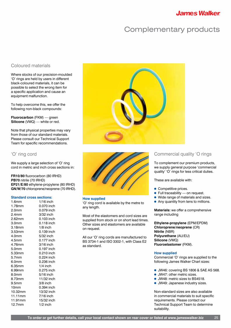
To order or get further details, call your local contact shown on rear cover or listed at www.jameswalker.biz 25
Header
To order or get further details, call your local contact shown on rear cover or listed at www.jameswalker.biz 25
Complementary products
Coloured materials
Where stocks of our precision-moulded ‘O’ rings are held by users in different black-coloured materials, it can be possible to select the wrong item for a specific application and cause an equipment malfunction.
To help overcome this, we offer the following non-black compounds:
Fluorocarbon (FKM) — greenSilicone (VMQ) — white or red.
Note that physical properties may vary from those of our standard materials. Please consult our Technical Support Team for specific recommendations.
‘O’ ring cord
We supply a large selection of ‘O’ ring cord in metric and inch cross sections in:
FR10/80 fluorocarbon (80 IRHD)PB70 nitrile (70 IRHD)EP21/E/80 ethylene-propylene (80 IRHD)GN/W/70 chloroprene/neoprene (70 IRHD).
Standard cross sections:1.6mm 1/16 inch1.78mm 0.070 inch 2.0mm 0.079 inch2.4mm 3/32 inch2.62mm 0.103 inch3.0mm 0.118 inch3.18mm 1/8 inch3.53mm 0.139 inch4.0mm 5/32 inch4.5mm 0.177 inch4.76mm 3/16 inch5.0mm 0.197 inch5.33mm 0.210 inch5.7mm 0.224 inch6.0mm 0.236 inch6.35mm 1/4 inch6.99mm 0.275 inch8.0mm 5/16 inch8.73mm 11/32 inch9.5mm 3/8 inch10mm 0.394 inch10.32mm 13/32 inch11.11mm 7/16 inch11.91mm 15/32 inch12.7mm 1/2 inch
How supplied ‘O’ ring cord is available by the metre to any length.
Most of the elastomers and cord sizes are supplied from stock or on short lead times. Other sizes and elastomers are available on request.
All our ‘O’ ring cords are manufactured to BS 3734-1 and ISO 3302-1, with Class E2 as standard.
Commercial quality ‘O rings
To complement our premium products, we supply general purpose ‘commercial quality’ ‘O’ rings for less critical duties.
These are available with:
l Competitive prices.l Full traceability — on request.l Wide range of materials and sizes.l Any quantity from tens to millions.
Materials: we offer a comprehensive range including
Ethylene-propylene (EPM/EPDM)Chloroprene/neoprene (CR)Nitrile (NBR)Polyurethane (AU/EU)Silicone (VMQ)Fluoroelastomer (FKM).
How suppliedCommercial ‘O’ rings are supplied to the following James Walker Chart sizes:
l JW46: covering BS 1806 & SAE AS 568.l JW47: other metric sizes.l JW48: metric sizes to BS4518. l JW49: Japanese industry sizes.
Non-standard sizes are also available in commercial materials to suit specific requirements. Please contact our Technical Support Team to determine suitability.

To order or get further details, call your local contact shown on rear cover or listed at www.jameswalker.biz26
Complementary products
‘O ring kits
These three boxed kits offer excellent value for money in terms of quantity, quality and convenience.
They are recommended for maintenance engineers and equipment refurbishers who need a good selection of nitrile (NBR) ‘O’ rings constantly available to suit general industrial applications.
The boxes are designed to withstand industrial maintenance activities, and have partitions to hold all items separately and securely. From the kit layouts, users can readily see when they are running low on a particular size of ring or cord.
‘O’ ring sealing kit — metric sizes(JW order code ZL000186)Box containing nitrile (NBR) elastomer rings of 70 IRHD:l 404 rings in total.l In 30 sizes ranging from 3mm ID x 2mm
section, up to 45mm ID x 4mm section.
‘O’ ring sealing kit — inch sizes(JW order code ZL000097)Box containing nitrile (NBR) elastomer rings of 70 IRHD:l 382 ‘O’ rings in total.l In 30 sizes ranging from 1/8 inch ID x
1/16 inch section, up to 1 3/4 inch ID x 3/16 inch section.
Service kit — ‘O’ ring cord(JW order code ZL000275)Box containing tools and nitrile (NBR) elastomer ‘O’ ring cord of 70 IRHD.l 14 off 2m lengths: 1.78mm (0.070 inch)
diameter, 2.0mm, 2.4mm, 2.62mm (0103 inch), 3.0mm, 3.5mm, (0.138 inch), 4.0mm, 4.5mm, 5.0mm, 5.33mm (0.210 inch), 5.7mm, 6.0mm, 6.99mm (0.275 inch), 8.0mm.
l Tape measure, retractable blade knife, splicing aid, adhesive for forming rings, and full instructions.
Note: Rubber hardness values (IRHD) quoted are nominal.
Special packaging & kits
Special packaging and bagging can be provided for all our ‘O’ rings. These range from individual bagged rings, to complete sealing kits containing a variety of sizes and materials suitable for refurbishing a specific item of equipment.
Bags and kits can be custom-branded and over printed with dedicated part numbers to simplify ordering, stocking and issuing routines.
In addition, your company name and logo can be printed on the bag or label to provide a custom packaged kit with your own references.This will save additional repackaging if you are re-selling.
‘O’ ring lubricants
We recommend the following lubricants be applied lightly to ‘O’ rings before assembly (but please note the important Exceptions):
l James Walker Molyon Grease containing MoS2, for operating temperatures from -20°C to +150°C.
l James Walker Silicone Grease, for operating temperatures from -50°C to +200°C.
l James Walker Copper Anti-Seize Compound or Nickel Anti-Seize Compound, for operating temperatures above +200°C.
ExceptionsDO NOT use mineral-based oil or grease, such as our Molyon and Anti-Seize Compounds on seals made from natural rubber (NR), butyl (IIR) or ethylene-propylene (EPM/EPDM). Likewise, DO NOT use Silicone Grease or oil on seals made from silicone (VMQ) compounds.

To order or get further details, call your local contact shown on rear cover or listed at www.jameswalker.biz 27
General design notes
How ‘O’ rings workRubber has a very high bulk modulus and is therefore virtually incompressible. This means that an ‘O’ ring must be deformed on the diameter section to give it an initial sealing force within a housing (Figure 1).
When system pressure is applied, the ‘O’ ring deforms further (Figure 2). But because of the initial squeeze, the sealing force always exceeds the force exerted on the ‘O’ ring by the system pressure.
At higher pressures, back-up rings may be required to prevent ‘O’ ring extrusion (see page 12). Leakage problems often arise due to lack of initial squeeze, or the ‘O’ ring diameter section being too large for its housing.
Reciprocating applications‘O’ rings marked with an asterisk (*) on our charts can be used for both static and light/medium reciprocating duties. Other sizes are not recommended for these dynamic applications.
Rotary applications‘O’ rings may be used for rotating applications where peripheral speeds are low. Please contact our Technical Support Team for recommendations.
Pressure
Pressure
G2
G2
G2
G2
Pressure
Pressure
G2
G2
G2
G2
Figure 1
Figure 2
Non-standard housing diametersIndividual rings can be stretched or squeezed very slightly to fit housing diameters that do not match the dimensions specified on our ‘O’ ring size charts.
The amount of allowable deformation varies according to the application, as follows:
l Groove in cylinder application:A maximum of 3 per cent squeeze is acceptable on an ‘O’ ring outside diameter to fit a shaft diameter C that is not covered by JW chart sizes. (See Figs 5 & 6, page 29.)
l Groove in piston application:A maximum of 4 per cent stretch is acceptable on an ‘O’ ring inside diameter to fit a cylinder diameter D that is not covered by JW chart sizes. (See Figs 7 & 8, page 29.)
l Flange and triangular groove applications: A maximum of 2 percent stretch is acceptable on an ‘O’ ring inside diameter when the seal is used on an external pressure flange, or housed in a triangular groove. (See Fig 9, page 29.)Likewise, a maximum of 1 per cent squeeze is acceptable on an ‘O’ ring outside diameter when the seal is used on an internal pressure flange. (See Fig 10, page 29.)
Cylinder and piston housing tolerancesIt is important that tolerances on housing diameters for cylinders and pistons meet the requirements of the formulae given on page 29 (ie, dimensions C and D in Figures 5-8).
Surface finish of metal partsFor maximum seal life the surface finish of metal parts in contact with an ‘O’ ring should not exceed:
l 0.8µm (32µin) CLA or Ra for static parts.
l 0.4µm (16µin) CLA or Ra for moving parts.
A finish finer than 0.15µm (6µin) should be avoided in dynamic applications as a lubricating film may not be retained. For details of these finishes, please refer to BS 1134: Assessment of surface texture.
Diametral clearance GUnder no circumstances should the maximum total diametral clearance (G max) indicated on our housing tables (pages 30-31) be exceeded. This is to ensure that, if complete shaft offset occurs, the maximum extrusion gap at any point on the ‘O’ ring does not exceed G.
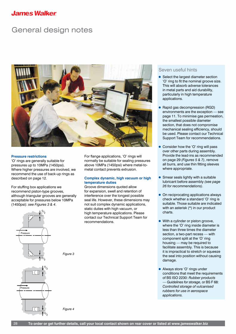
To order or get further details, call your local contact shown on rear cover or listed at www.jameswalker.biz28 To order or get further details, call your local contact shown on rear cover or listed at www.jameswalker.biz28
General design notes
Pressure restrictions‘O’ rings are generally suitable for pressures up to 10MPa (1450psi). Where higher pressures are involved, we recommend the use of back-up rings as described on page 12.
For stuffing box applications we recommend piston-type grooves, although triangular grooves are generally acceptable for pressures below 10MPa (1450psi): see Figures 3 & 4.
For flange applications, ‘O’ rings will normally be suitable for sealing pressures above 10MPa (1450psi) where metal-to-metal contact prevents extrusion.
Complex dynamic, high vacuum or high temperature dutiesGroove dimensions quoted allow for expansion, swell and retention of interference over the longest possible seal life. However, these dimensions may not suit complex dynamic applications, static duties with high vacuum, or high temperature applications. Please contact our Technical Support Team for recommendations.
Seven useful hintsl Select the largest diameter section
‘O’ ring to fit the nominal groove size. This will absorb adverse tolerances in metal parts and aid durability, particularly in high temperature applications.
l Rapid gas decompression (RGD) environments are the exception — see page 11. To minimise gas permeation, the smallest possible diameter section, that does not compromise mechanical sealing efficiency, should be used. Please contact our Technical Support Team for recommendations.
l Consider how the ‘O’ ring will pass over other parts during assembly. Provide the lead-ins as recommended on page 29 (Figures 5 & 7), remove all burrs, and use thin fitting sleeves where appropriate.
l Smear seals lightly with a suitable lubricant before assembly (see page 26 for recommendations).
l On reciprocating applications always check whether a standard ‘O’ ring is suitable. Those suitable are indicated with an asterisk (*) in our product charts.
l With a cylinder or piston groove, where the ‘O’ ring inside diameter is less than three times the diameter section, a two-part recess — with component split at the ‘O’ ring housing — may be required to facilitate assembly. This is because it is impractical to stretch or squeeze the seal into position without causing damage.
l Always store ‘O’ rings under conditions that meet the requirements of BS ISO 2230: Rubber products — Guidelines for storage, or BS F 68: Controlled storage of vulcanised rubbers for use in aerospace applications.
Pressure
Pressure
G2
G2
G2
G2
Pressure
Pressure
G2
G2
G2
G2
Figure 3
Figure 4

To order or get further details, call your local contact shown on rear cover or listed at www.jameswalker.biz 29
Housing design
‘O’ ring design notes – Housings for general service
Housing arrangements
Figure 5: Groove in cylinder Figure 9: Groove in flange, external pressure
Figure 6: Plug groove, terminology as figures 5 and 14
Figure 13: Dovetail groove
Figure 12: Triangular groove
G totaldiametralclearance
Maximum radius R
Maximum radius 2G
Radiusmin. Gmax. 2G
G totaldiametralclearance
Directionof pressure Radius
R1 max.RadiusR2
0 – 5°
B
A
K
H
P h11
Figure 10: Groove in flange, internal pressure
Directionof pressure
K
H
Q H11
Max. groove dia. = D min. – 2F min.Min. groove dia. = D max. – 2F max.
G totaldiametralclearance
Shaftdiameter15 – 20°
Groove diameter
Max. groove dia. = C min. + 2F max.Min. groove dia. = C max. + 2F min.
E
F
15 – 20°
20 – 25°A + B
45°
DCylinderdiameter
Groovediameter
E
F
M
L
Figure 11: Groove in flange, Chart 72
H
W
V
T
X
Y
Figure 7: Groove in pistonMin. lead in dia. Max. groove dia. + 2A max. + G=
Max. lead in dia. Min. groove dia. – 2A max. – G=
List of symbols
The following symbols are used throughout this guide:
A ‘O’ ring diameter section
B ‘O’ ring inside diameter
C Shaft diameter
D Cylinder diameter
E Groove width
F Groove radial depth
G Maximum diametral clearance
H Flange groove depth
h11 BS EN ISO 286-2 tolerance (shafts)
H11 BS EN ISO 286-2 tolerance (holes)
K Minimum flange groove width
L Minimum spigot length
M Triangular groove chamfer
P Flange groove inside diameter
Q Flange groove outside diameter
R Triangular groove radius
R1 Corner radius (maximum) at groove base
R2 Corner radius at groove entrance
T Triangular groove inside diameter
V BS 4518 flange groove inside diameter
W BS 4518 flange groove outside diameter
X Dovetail groove depth
Y Dovetail groove width
Figure 14: Groove radii and taper for figures 5 –11
Figure 8: Plug groove, terminology as figures 7 and 14

Header
To order or get further details, call your local contact shown on rear cover or listed at www.jameswalker.biz30
Housing design
Key: Chart 50 Chart 72 Chart 17000
# Diameter section A indicated is too small for this groove type.† These dimensions can be used only with moulded ‘O’ rings. Use tables for Triangular groove sizes and Dovetail groove sizes on
page 31 for ‘O’ rings manufactured by other methods.
Metric Groove Dimensions All dimensions in millimetres. Diameter Groove Width E Radial Diametrical Flange Groove Triangular Groove Groove Radii Dovetail Groove Section Depth Clearance A ‘O’ring only +1 back-up +2 back-up F G max Depth H K min L min Chamfer M R max R1 max R2 Depth X Width Y
1.0/1.02 1.5/1.6 # # 0.81/0.86 0.11 0.7/0.8 1.8 # # # 0.2 0.11/0.22 # # 1.27 1.8/1.9 # # 1.06/1.11 0.11 0.9/1.0 2.1 # # # 0.3 0.11/0.22 # # 1.5/1.52 2.1/2.2 # # 1.26/1.32 0.12 1.1/1.2 2.4 3.0 2.08/2.20 0.8 0.3 0.12/0.24 # # 1.6 2.3/2.5 3.7/3.9 5.0/5.2 1.18/1.25 0.12 1.2/1.3 2.4 4.0 2.20/2.32 0.8 0.2 0.20/0.40 1.37/1.43 1.34/1.40 1.78 2.3/2.5 3.8/3.9 5.3/5.4 1.52/1.57 0.13 1.3/1.5 2.4 4.8 2.41/2.54 0.8 0.8 0.13/0.25 1.50/1.56 1.50/1.56
2.0 2.6/2.7 4.1/4.2 5.6/5.7 1.72/1.79 0.12 1.6/1.7 2.8 4.0 2.71/2.83 1.0 0.4 0.12/0.24 1.65/1.72 1.70/1.77 2.4 3.2/3.4 4.6/4.8 6.0/6.2 1.97/2.09 0.14 1.7/1.8 3.7 5.0 3.30/3.42 1.3 0.5 0.20/0.40 1.96/2.04 2.05/2.13 2.5 3.2/3.3 4.7/4.8 6.2/6.3 2.17/2.25 0.13 2.0/2.1 3.4 5.0 3.46/3.59 1.3 0.5 0.13/0.26 2.05/2.13 2.15/2.23 2.62 3.5/3.7 5.0/5.1 6.5/6.6 2.31/2.39 0.13 2.1/2.3 3.6 6.4 3.68/3.81 1.0 0.8 0.13/0.25 2.16/2.24 2.26/2.34 3.0 4.0/4.2 5.4/5.6 6.8/7.0 2.50/2.65 0.15 2.2/2.3 4.5 6.0 4.20/4.32† 2.0 1.0 0.20/0.40 2.46/2.55† 2.58/2.67
3.5/3.53 4.7/4.9 6.2/6.4 7.7/7.9 3.10/3.18 0.15 2.8/3.0 4.8 7.9 4.95/5.08† 1.5 0.8 0.13/0.25 2.89/2.99† 3.03/3.13 4.0 5.1/5.3 6.6/6.8 8.1/8.3 3.52/3.62 0.15 3.2/3.4 5.5 8.0 5.75/5.90 2.0 0.8 0.15/0.30 3.32/3.42† 3.48/3.58 4.1 5.5/5.7 7.1/7.3 8.7/8.9 3.50/3.67 0.16 3.1/3.2 6.0 8.0 5.60/5.72† 2.5 1.0 0.20/0.40 3.39/3.50† 3.59/3.70 4.5 5.8/6.0 7.6/7.8 9.4/9.6 3.96/4.07 0.16 3.7/3.9 6.0 9.0 6.45/6.61 2.3 0.9 0.16/0.32 3.74/3.85† 3.92/4.03 5.0 6.4/6.6 8.2/8.4 10.0/10.2 4.42/4.54 0.16 4.1/4.3 6.7 10.0 7.18/7.34 2.5 1.0 0.16/0.32 4.23/4.35 4.37/4.49
5.33 7.0/7.2 8.8/9.0 10.6/10.8 4.67/4.78 0.18 4.3/4.5 7.1 11.1 7.49/7.62 2.3 0.8 0.13/0.25 4.54/4.67 4.64/4.77 5.7 7.5/7.7 9.3/9.5 11.1/11.3 4.95/5.18 0.18 4.4/4.5 8.1 10.0 7.80/7.92† 3.0 1.0 0.20/0.40 4.80/4.94 4.98/5.12 6.0 7.8/8.0 9.6/9.8 11.4/11.6 5.31/5.45 0.18 5.0/5.2 7.9 12.0 8.64/8.82 3.0 1.2 0.18/0.36 5.02/5.16 5.25/5.39 6.99/7.0 9.4/9.6 12.0/12.2 14.6/14.8 6.22/6.35 0.20 5.9/6.1 9.4 14.3 10.03/10.16 2.5 0.8 0.13/0.25 5.85/6.01 6.12/6.28 8.0 10.7/10.9 13.3/13.5 15.9/16.1 7.09/7.27 0.20 6.7/6.9 10.6 16.0 11.61/11.81 4.0 1.6 0.20/0.40 6.70/6.88 7.01/7.19
8.4 11.0/11.2 13.6/13.8 16.2/16.4 7.50/7.75 0.20 6.6/6.7 12.0 14.0 11.50/11.62† 4.0 1.0 0.20/0.40 7.02/7.21 7.34/7.53 9.0 12.3/12.5 15.6/15.8 18.9/19.1 7.97/8.17 0.21 7.5/7.7 12.1 18.0 13.08/13.29 4.5 1.8 0.21/0.42 7.54/7.74 7.89/8.09 9.5/9.53 13.1/13.3 16.4/16.6 19.7/19.9 8.43/8.64 0.22 8.0/8.2 12.7 19.0 13.83/14.05 4.8 1.9 0.22/0.44 7.97/8.18 8.34/8.55 10.0 13.8/14.0 17.1/17.3 20.4/20.6 8.89/9.10 0.23 8.4/8.6 13.3 20.0 14.58/14.81 5.0 2.0 0.23/0.46 8.41/8.62 8.80/9.01 12.5/12.7 18.5/18.8 21.8/22.1 25.1/25.4 11.13/11.39 0.26 10.5/10.8 17.4 25.0 18.30/18.56 6.3 2.5 0.26/0.52 10.52/10.78 11.01/11.27
Inch Groove Dimensions All dimensions in inches. Diameter Groove Width E Radial Diametrical Flange Groove Triangular Groove Groove Radii Dovetail Groove Section Depth Clearance A ‘O’ring only +1 back-up +2 back-up F G max Depth H K min L min Chamfer M R max R1 max R2 Depth X Width Y
0.040 .059/.063 # # .032/.034 .004 .028/.032 .068 # # # .008 .004/.008 # # 0.050 .069/.073 # # .042/.044 .004 .037/.041 .078 # # # .010 .004/.008 # # 0.060 .080/.085 # # .051/.053 .005 .045/.050 .091 .120 .082/.087 .030 .012 .005/.010 # # 0.063 .084/.089 .142/.147 .200/.205 .053/.055 .005 .047/.052 .094 .125 .086/.091 .031 .013 .005/.010 .054/.056 .053/.055 0.070 .089/.099 .147/.152 .205/.210 .060/.062 .005 .051/.061 .095 .188 .095/.100 .030 .030 .005/.010 .059/.062 .059/.062
0.094 .121/.126 .179/.184 .237/.242 .081/.084 .005 .075/.080 .129 .188 .129/.134 .047 .019 .005/.010 .077/.080 .080/.083 0.103 .136/.146 .194/.199 .252/.257 .091/.094 .005 .081/.091 .140 .250 .145/.150 .040 .030 .005/.010 .085/.088 .089/.092 0.125 .159/.164 .217/.222 .275/.280 .110/.114 .005 .102/.107 .168 .250 .183/.188 .063 .025 .005/.010 .103/.107† .107/.111 0.139 .183/.193 .241/.247 .299/.305 .122/.125 .006 .110/.120 .190 .313 .195/.200† .060 .030 .005/.010 .115/.119† .120/.124 0.188 .240/.246 .312/.318 .384/.390 .166/.171 .006 .155/.161 .248 .375 .269/.275 .094 .038 .006/.012 .156/.161† .163/.168
0.210 .276/.286 .348/.355 .420/.427 .184/.188 .007 .170/.180 .280 .438 .295/.300 .090 .030 .005/.010 .179/.184 .183/.188 0.250 .328/335 .430/.437 .532/.539 .221/.227 .007 .207/.214 .333 .500 .360/.367 .125 .050 .007/.014 .208/.214 .218/.224 0.275 .370/.380 .472/.480 .574/.582 .245/.250 .008 .231/.241 .370 .563 .395/.400 .100 .030 .005/.010 .230/.236 .241/.247 0.375 .514/.523 .644/.653 .774/.783 .333/.341 .009 .314/.323 .501 .750 .545/.554 .188 .075 .009/.018 .315/.323 .329/.337 0.500 .718/.728 .848/.858 .978/.988 .446/.456 .010 .421/.431 .674 1.000 .733/.743 .250 .100 .010/.020 .421/.431 .441/.451
Figures in red relate to BS 1806, BS 4518 and BS 5106. Please contact our Technical Support Team for housings to BS ISO 3601-2 Fluid power systems — ‘O’ rings — Part 2: Housing dimensions for general applications.

To order or get further details, call your local contact shown on rear cover or listed at www.jameswalker.biz 31
Housing design
For ‘O’ rings manufactured by extrusion
ISO 286-2 Limits and Fits Extract (See Figures 9 - 11, page 29)
Nom. Diameter Tolerance up to and Above including H11 h11
- 3 +0/+0.060 –0/–0.060 3 6 +0/+0.075 –0/–0.075 6 10 +0/+0.090 –0/–0.090 10 18 +0/+0.110 –0/–0.110 18 30 +0/+0.130 –0/–0.130
30 50 +0/+0.160 –0/–0.160 50 80 +0/+0.190 –0/–0.190 80 120 +0/+0.220 –0/–0.220 120 180 +0/+0.250 –0/–0.250 180 250 +0/+0.290 –0/–0.290
continued
Nom. Diameter Tolerance up to and Above including H11 h11
250 315 +0/+0.320 –0/–0.320 315 400 +0/+0.360 –0/–0.360 400 500 +0/+0.400 –0/–0.400 500 630 +0/+0.440 –0/–0.440 630 800 +0/+0.500 –0/–0.500
800 1000 +0/+0.560 –0/–0.560 1000 1250 +0/+0.660 –0/–0.660 1250 1600 +0/+0.780 –0/–0.780 1600 2000 +0/+0.920 –0/–0.920 2000 2500 +0/+1.100 –0/–1.100 2500 3150 +0/+1.350 -0/-1.350
All dimensions in millimetres
Triangular DovetailGroove Sizes Groove Sizes
Diameter Triangular Diameter Dovetail Section A Chamfer M Section A Depth X
Metric (mm) Metric (mm)
3.0 4.48/4.63 3.0 ¥ 3.5/3.53 5.10/5.25 3.5/3.53 ¥ 4.1 6.00/6.16 4.0 3.48/3.58 5.7 8.18/8.36 4.1 3.59/3.70 8.4 12.18/12.38 4.5 3.88/3.99
Inch Inch
0.139 .201/.207 0.125 ¥ 0.139 ¥ 0.188 .159/.164
¥ ’O’ rings not suitable for dovetail grooves.
Trademark acknowledgements
James Walker acknowledges the following trademarks as mentionedin this guide. All other names bearing the ® symbol are registeredtrademarks of James Walker.
Aflas® Asahi Glass
Dyneon™ 3M Dyneon
Kalrez® DuPont Performance Elastomers
PEEK™ Victrex plc
Tecnoflon® Solvay Solexis
Viton® DuPont Performance Elastomers
General information
Health warning: If PTFE or fluoroelastomer (eg, FKM, FFKM, FEPM) products are heated to elevated temperatures, fumes will be produced which may give unpleasant effects, if inhaled. Whilst some fumes are emitted below 250°C from fluoroelastomers or below 300°C from PTFE, the effect at these temperatures is negligible. Care should be taken to avoid contaminating tobacco with particles of PTFE or fluoroelastomer, or with PTFE dispersion, which may remain on hands or clothing. Material Safety Data Sheets (MSDS) are available on request. Information in this publication and otherwise supplied to users is based on our general experience and is given in good faith, but because of factors which are outside our knowledge and control and affect the use of products, no warranty is given or is to be implied with respect to such information. Unless governed by type approval or contract, specifications are subject to change without notice. Statements of operating limits quoted in this publication are not an indication that these values can be applied simultaneously.
To ensure you are working with the very latest product specifications, please consult the relevant section of the James Walker website: www.jameswalker.biz.

Registered Office: Lion House, Oriental Road, Woking, Surrey GU22 8AP, United Kingdom. Reg No. 2432592 England© James Walker 2010
James Walker & Co LtdCustomer Support Centre1 Millennium Gate, Westmere Drive Crewe, Cheshire CW1 6AY, UKTel: +44 (0)1270 536000Fax: +44 (0)1270 536100Email: [email protected]
James Walker & CoTel: +44 (0)1270 536000Fax: +44 (0)1270 536100Email: [email protected]
James Walker AustraliaTel: +61 (0)2 9721 9500Fax: +61 (0)2 9721 9580Email: [email protected]
James Walker Benelux(Belgium) Tel: +32 3 820 7900Fax: +32 3 828 5484Email: [email protected](Netherlands)Tel: +31 (0)186 633111Fax: +31 (0)186 633110Email: [email protected]
James Walker BrasilTel: +55 21 2220 2152Fax: +55 21 253 11704Email: [email protected]
James Walker ChinaTel: +86 21 6876 9351Fax: +86 21 6876 9352Email: [email protected]
James Walker DeutschlandTel: +49 (0)40 386 0810Fax: +49 (0)40 389 3230Email: [email protected]
James Walker FranceTel: +33 (0)437 497 480Fax: +33 (0)437 497 483Email: [email protected]
James Walker IbericaTel: +34 94 447 0099Fax: +34 94 447 1077Email: [email protected]
James Walker IrelandTel: +353 (0)21 432 3626Fax: +353 (0)21 432 3623Email: [email protected]
James Walker ItalianaTel: +39 02 257 8308Fax: +39 02 263 00487Email: [email protected]
James Walker Mfg (USA)Tel: +1 708 754 4020Fax: +1 708 754 4058Email: [email protected]
James Walker New ZealandTel: +64 (0)9 272 1599Fax: +64 (0)9 272 3061Email: [email protected]
James Walker NorgeTel: +47 22 706800Fax: +47 22 706801Email: [email protected]
James Walker Oil & Gas (USA)Tel: +1 281 875 0002Fax: +1 281 875 0188Email: [email protected]
James Walker SingaporeTel: +65 6777 9896Fax: +65 6777 6102Email: [email protected]
James Walker South AfricaTel: +27 (0)31 205 6251/2/3Fax: +27 (0)31 205 6266Email: [email protected]
James Walker companies worldwide
CERTIFICATE No. FM 01269BS EN 9100:2003
BS EN ISO 9001:2008
BP4179 910/5m ML011653


![[Walker R.G. James N.P.] Facies Models Response (BookFi.org)](https://static.fdocuments.in/doc/165x107/577ccf1a1a28ab9e788ee15e/walker-rg-james-np-facies-models-response-bookfiorg.jpg)

