James, O. N. , Hilton, G., & Beach, M. (2017). Radiation ...
6
James, O. N., Hilton, G., & Beach, M. (2017). Radiation Efficiency Analysis of Balanced-Impedance Hexaferrite Substrate for Antenna Miniaturisation. In 2017 Loughborough Antennas & Propagation Conference (LAPC 2017) (pp. 11-15). Institution of Engineering and Technology (IET). https://doi.org/10.1049/cp.2017.0235 Peer reviewed version License (if available): Unspecified Link to published version (if available): 10.1049/cp.2017.0235 Link to publication record in Explore Bristol Research PDF-document This is the author accepted manuscript (AAM). The final published version (version of record) is available online via IET at http://digital-library.theiet.org/content/conferences/10.1049/cp.2017.0235 . Please refer to any applicable terms of use of the publisher. University of Bristol - Explore Bristol Research General rights This document is made available in accordance with publisher policies. Please cite only the published version using the reference above. Full terms of use are available: http://www.bristol.ac.uk/red/research-policy/pure/user-guides/ebr-terms/
Transcript of James, O. N. , Hilton, G., & Beach, M. (2017). Radiation ...

James, O. N., Hilton, G., & Beach, M. (2017). Radiation EfficiencyAnalysis of Balanced-Impedance Hexaferrite Substrate for AntennaMiniaturisation. In 2017 Loughborough Antennas & PropagationConference (LAPC 2017) (pp. 11-15). Institution of Engineering andTechnology (IET). https://doi.org/10.1049/cp.2017.0235
Peer reviewed versionLicense (if available):UnspecifiedLink to published version (if available):10.1049/cp.2017.0235
Link to publication record in Explore Bristol ResearchPDF-document
This is the author accepted manuscript (AAM). The final published version (version of record) is available onlinevia IET at http://digital-library.theiet.org/content/conferences/10.1049/cp.2017.0235 . Please refer to anyapplicable terms of use of the publisher.
University of Bristol - Explore Bristol ResearchGeneral rights
This document is made available in accordance with publisher policies. Please cite only thepublished version using the reference above. Full terms of use are available:http://www.bristol.ac.uk/red/research-policy/pure/user-guides/ebr-terms/

Radiation Efficiency Analysis of Balanced-Impedance HexaferriteSubstrate for Antenna Miniaturisation
O N James, G S Hilton, M A Beach
Communications Systems and Networks Group, University of Bristol, [email protected]
Keywords: Antenna miniaturisation, electrically small anten-nas, hexagonal ferrite, radiation efficiency, radiation patterns.
AbstractAntenna miniaturisation in the low UHF band is required sincethe wavelengths are large compared to portable consumer termi-nals. Magneto-dielectric substrates such as hexaferrites whichincrease µr as well as εr have received attention for their minia-turisation potential, however there is a shortage of publishedresults for the radiation efficiency of such antennas based onfull 3D radiative characterisation in free space conditions. Inthis work, patch antennas fabricated on hexaferrite, FR-4 andRT5880 substrates were examined through simulation, fabrica-tion and radiative measurement. While the frequency in hexa-ferrite was reduced by a factor of six compared to the RT5880antennas, the efficiency in the hexaferrite antennas was low.The combined effect of the losses in the hexaferrite and theelectrically small size of the resulting patch antenna limits itsuse in long range transmitting applications, though it may stillfind application in short range or receiver applications.
1 IntroductionThere is an ongoing need for antenna developments in thelow UHF band below 1000 MHz. Vacation of the analogueTV broadcast bands offers the opportunity to deploy “whites-pace” devices in the band 470–790 MHz [1, 2]. Similarly,control-plane communications for 5G and increasing volumeof machine-to-machine communication can utilise the long-range, low-data rate channels associated with the low UHFband. Alternatively, short range UHF applications exist in thecontext of RFID readers and wireless medical devices [3]. Inany of these cases the wavelengths involved necessitate antennaminiaturisation in consumer devices.
Many examples exist of patch antenna miniaturisation with asubstrate of dielectric permittivity εr. While the patch antennaoffers favourable broadbeam radiation pattern characteristicsand reasonable efficiency provided the dielectric losses are low[4], the miniaturisation offered by the wavelength compressionpotentially requires very high dielectric permittivity values εr tocompress the large wavelengths into an acceptable volume. Thepatch antenna is known to be intrinsically relatively narrowband
compared to the half-wavelength wire dipole for example [4],with the bandwidth still further reduced by increased εr [5].
Magneto-dielectric substrate materials have been proposed tocounter the bandwidth problems associated with patch antennaminiaturisation [5]. Increasing both magnetic permeability µrand εr greatly increases the resultant antenna miniaturisation,reducing the bandwidth reduction associated with high valuesof increasing εr [5]. While magneto-dielectric loading elementshave been tested in various forms to provide varying degrees ofantenna miniaturisation [3, 6, 7, 8, 9, 10, 11, 12], there is a short-age of works recording the full 3D radiative characterisation ofthese antennas using these substrates.
In this work a balanced-impedance hexaferrite (HXF) material,as well as samples of FR-4 and Rogers RT5880, were charac-terised using a Keysight E4991B impedance analyser. The 3Dradiation patterns and efficiency characteristics of patch anten-nas built on these substrates were then analysed in simulation(CST Microwave Studio) and free space radiative measurement.
2 Background
2.1 Balanced wave impedance and hexaferrites
A theoretical lossless magneto-dielectric substrate for patch an-tennas was examined in [5]. That work inspired many others bynoting that patch antenna bandwidth would be degraded moreslowly with increasing miniaturisation factor n =
√µr × εr,
if increased µr was used to provide some of the increase inrefractive index n as opposed to increasing εr in isolation. Inaddition to achieving high n, various authors have attempted tosatisfy the “balanced wave impedance” criterion during materialdesign [7, 13], wherein satisfying µr = εr causes the materialto exhibit the same wave impedance as free space [13], givingthe patch similar bandwidth to the same-sized patch with nosubstrate [5]. The wave impedance Z is given by:
Z =
�µr
εr× 377 Ω (1)
For antenna applications at UHF frequencies, hexaferrites arecomparatively unique in offering control over µr and εr at fre-quencies not coincident with extremely lossy ferromagneticresonances associated with common spinel and Ni-Zn ferrites[6]. Observation of the recent literature indicates that while
1
µr and εr can be controlled, minimum loss tangent may notcoincide with the desired µr and εr values at a target frequency[7, 13]. Thus, the bandwidth advantage conferred by impedancematching the substrate to the channel may be nullified by highloss tangent, resulting in low efficiency.
2.2 Review of hexaferrite antennas
Various miniaturised antennas have been reported with hexafer-rite elements, including wire-wound conductors on hexaferritechips [8, 9] and patches with substrates that were solid tiles[10, 11], flexible [3] or a lattice of hexaferrite bars [12]. Whileall of these works observed miniaturisation, varying approachesto performance analysis especially with regard to the treatmentof loss tangent and efficiency lead to differing conclusions onthe applicability of the antenna to various communication prob-lems.
Where high radiation efficiencies have been reported, these ap-pear to be limited to designs which use hexaferrite chip loadingelements such as [8, 9, 12], where the miniaturisation is less pro-nounced than that observed in conventional patch designs dueto the lower filling factor. Conventional patch designs achievegreater miniaturisation [10, 11, 3] but the utility of these designsfor common communication problems depends on whether losstangent and efficiency has been given full consideration. Theworks of [10, 11] overlook loss tangent, wherein LTE MIMOis proposed as a possible application. Without an analysis ofloss tangent, this view may be compromised by low radiationefficiency.
In contrast, works presenting detailed analysis of the loss tan-gents in hexaferrite patches such as [3] advance the view thathexaferrite patches are mostly applicable to short range com-munications such as RFID or health monitoring. The lowgain of even relatively low-loss hexaferrites makes hexafer-rite miniaturisation best suited to cases where miniaturisation isof paramount importance compared to concerns of efficiency.
3 Antenna design
3.1 Material characterisation
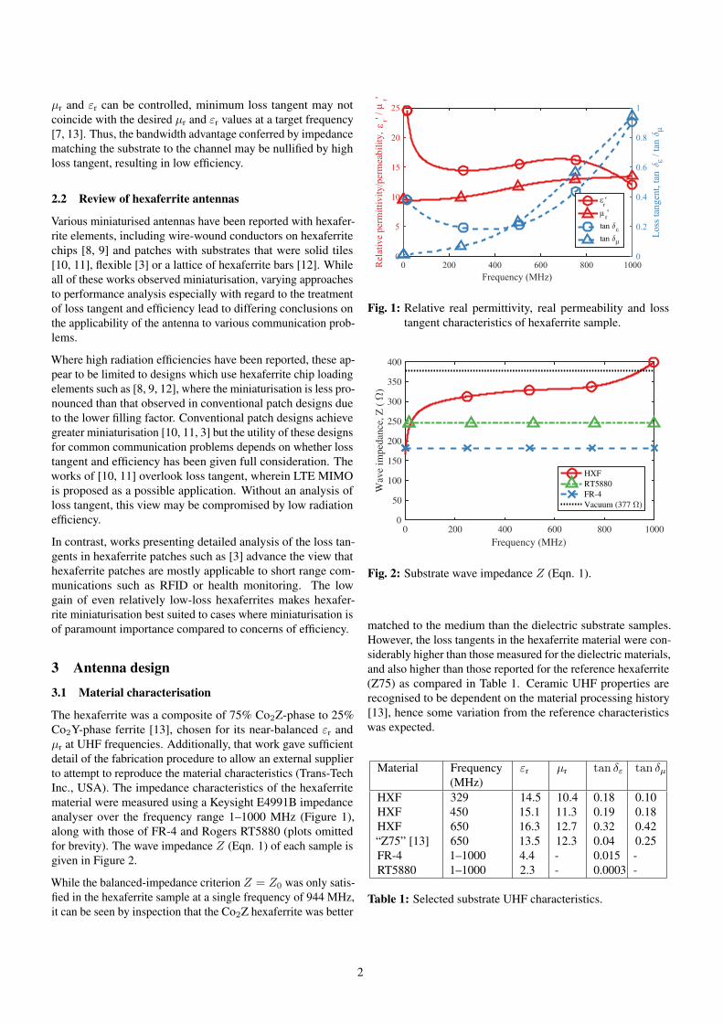
The hexaferrite was a composite of 75% Co2Z-phase to 25%Co2Y-phase ferrite [13], chosen for its near-balanced εr andµr at UHF frequencies. Additionally, that work gave sufficientdetail of the fabrication procedure to allow an external supplierto attempt to reproduce the material characteristics (Trans-TechInc., USA). The impedance characteristics of the hexaferritematerial were measured using a Keysight E4991B impedanceanalyser over the frequency range 1–1000 MHz (Figure 1),along with those of FR-4 and Rogers RT5880 (plots omittedfor brevity). The wave impedance Z (Eqn. 1) of each sample isgiven in Figure 2.
While the balanced-impedance criterion Z = Z0 was only satis-fied in the hexaferrite sample at a single frequency of 944 MHz,it can be seen by inspection that the Co2Z hexaferrite was better
εµ
εµ
ε
µ
ε
µ
Fig. 1: Relative real permittivity, real permeability and losstangent characteristics of hexaferrite sample.
0 200 400 600 800 1000Frequency (MHz)
0
50
100
150
200
250
300
350
400
Wav
e im
peda
nce,
Z (+
)
HXFRT5880FR-4Vacuum (377 +)
Fig. 2: Substrate wave impedance Z (Eqn. 1).
matched to the medium than the dielectric substrate samples.However, the loss tangents in the hexaferrite material were con-siderably higher than those measured for the dielectric materials,and also higher than those reported for the reference hexaferrite(Z75) as compared in Table 1. Ceramic UHF properties arerecognised to be dependent on the material processing history[13], hence some variation from the reference characteristicswas expected.
Material Frequency(MHz)
εr µr tan δε tan δµ
HXFHXFHXF“Z75” [13]FR-4RT5880
3294506506501–10001–1000
14.515.116.313.54.42.3
10.411.312.712.3--
0.180.190.320.040.0150.0003
0.100.180.420.25--
Table 1: Selected substrate UHF characteristics.
2

3.2 Antenna layout selection
A set of hexaferrite patch antennas were designed and simulatedwith the layouts given in Figure 3. The patch widths (50.0,35.0 mm) were selected to target two frequencies: the lowestfrequency available (subsequently measured to be 329 MHz),and 433 MHz (ISM band). The patch lengths (33.0, 15.0 mm)and feed track positions were selected to provide impedancematching to a 50 Ω coaxial line. The hexaferrite tiles werelimited to maximum dimensions of 50 mm × 50 mm × 2 mmby the manufacturing process. The dimensions were maintainedfor antennas fabricated on FR-4 and RT5880 substrate to permita study of antenna miniaturisation based predominantly on thechange in substrate, except for varying the feed position toobtain a suitable feed match.
50.0
35.0
50.0
50.0
33.0
3.08.540.5 33.5
(a) Large patch (b) Small patch
15.0
17.5
Fig. 3: Hexaferrite patch antenna layout. Dimensions in mm.
(a) Large patch (329 MHz) (b) Small patch (450 MHz)
Fig. 4: Fabricated hexaferrite patch antennas.
4 Antenna Measurements4.1 Input response
The simulated and measured input responses (S11) are shownin Figure 5, demonstrating the frequency reduction caused bythe increased refractive index of the hexaferrite material. Thefrequency reduction factor is given relative to the measuredfrequency of the RT5880 antenna in each case by f(RT5880)
f(meas)in Table 2. The electrical smallness factor ka = 2πa/λ0 iscalculated, where a = 35.4 mm is the radius of the smallestsphere inscribing the antenna and feed track within its limits.Antennas with ka factors smaller than 0.5 may be classed aselectrically small and are susceptible to exhibiting low radiationresistance rrad, which may subsequently lead to low radiationefficiency even for modest substrate loss factors [4].
0 500 1000 1500 2000 2500 3000Frequency (MHz)
-20
-15
-10
-5
0
S11
(dB
)
HXFFR-4RT5880
(a) Large patch
0 500 1000 1500 2000 2500 3000Frequency (MHz)
-20
-15
-10
-5
0
S11
(dB
)
HXFFR-4RT5880
(b) Small patch
Fig. 5: Input response S11 of patch antennas. Solid lines denotemeasured results, dashed lines denote simulated results.
Antenna Freq.(MHz)
Frequencyreduction factor
ka
HXF large 329 6.2 0.24FR-4 large 1514 1.3 1.12
RT5880 large 2042 (1) 1.51HXF small 450 6.4 0.33FR-4 large 2110 1.4 1.56
RT5880 large 2872 (1) 2.14
Table 2: Frequency reduction and electrical smallness ka.
4.2 Radiation patterns
The 3D measurement system is shown in Figure 6. The antennaunder test (AUT) was aligned in the xy-plane, centred on acircular ground plane measuring 400 mm in diameter.
3D rotating positioner
Port 1Port 2
Motor controller
ReferenceTx antenna
D >> λAnechoic chamber
z
Ground planey
AUT
VNA
Fig. 6: Radiation pattern measurement setup in anechoic cham-ber.
3D radiation patterns were recorded for two orthogonal polar-isations Eθ and Eφ, with positioner resolutions of Δθ = 1◦
3

and Δφ = 10◦. For brevity, only total power Etotal patternscan be given here. The power patterns measured at the reso-nant frequencies of the hexaferrite and RT5880 antennas arecompared to the simulated patterns in Figures 7 and 8. Thepatterns were consistent with the TM10 mode, with the patternsimilarity across the frequency range indicating that the radi-ating mode did not change. The increase in directivity withfrequency was an artefact of the increasing electrical size ofthe fixed ground plane with respect to the decreasing operatingwavelength, reducing diffraction into the −z hemisphere.
Sim. (HXF, 304 MHz) Meas. (HXF, 329 MHz)
Sim. (RT5880, 2014 MHz) Meas. (RT5880, 2042 MHz)
Fig. 7: Etotal directivity patterns for large patch antenna.
Sim. (HXF, 440 MHz) Meas. (HXF, 450 MHz)
Sim. (RT5880, 2823 MHz) Meas. (RT5880, 2872 MHz)
Fig. 8: Etotal directivity patterns for small patch antenna.
4.3 Radiation efficiency
The radiation efficiency was calculated via a pattern integra-tion method [14]. The total efficiency η = ηmηΩ is given byrearrangement of gain G = (ηmηΩ)D, with directivity D andmatching efficiency ηm. Radiation efficiency ηΩ consists oflosses in the conductor, the substrate and the radiation resis-tance rrad:
ηΩ,AUT =rrad
rrad + rloss(2)
The pattern-integrated received power of the AUT was mea-sured relative to that of a wire λ/4 monopole constructed foreach frequency to determine total efficiency ηmηΩ. The ratioof overall efficiencies ηAUT/ηref permits efficiency calculationsince the quarter-wave metallic monopole is recognised to behighly efficient [14], thus for comparison purposes it can beassigned a radiation efficiency value of ηΩ,ref = 1. Scaling themeasured overall efficiency ratio by the matching efficienciesyields a measure of the radiation efficiency for the AUT at eachfrequency:
ηΩ,AUT
(ηΩ,ref = 1)=
ηAUT
ηref× ηm, ref
ηm, AUT(3)
The radiation efficiencies given by Eqn. 3 are given in Figure 9for each of the antennas.
0 500 1000 1500 2000 2500 3000100
101
102
HXF: 1%FR-4: 20%RT5880: 69%HXF: 1%FR-4: 24%RT5880: 78%
Largepatch
Smallpatch
Fig. 9: Radiation efficiency relative to reference λ/4 wiremonopole of low loss.
The RT5880 substrates delivered greater radiation efficiencythan the FR-4 substrate, which was in turn much more efficientthan the hexaferrite substrate. This can be understood as acombined effect of increased loss tangent of hexaferrite and FR-4 than that of RT5880 and falling rrad as the electrical size ofthe antenna is reduced with respect to the free space wavelength(documented by the ka factor in Table 2).
Electrically small antennas with ka < 0.5 are recognised tobe susceptible to low radiation resistance, reducing efficiencyeven for fixed values of substrate loss (Eqn. 2) [4]. While thehexaferrite antennas remained resonant in terms of substratewavelength, they nevertheless had small physical apertures.The authors therefore contend that while the loss tangents ofthe hexaferrite materials in development might be considered
4

low with respect to other ferrites in the UHF band by materialscientists [13], the loss tangents need to be reduced much moreaggressively to cope with the reduced rrad coincident with theenhanced miniaturisation offered by hexaferrite substrates.
5 Conclusions
A magneto-dielectric hexaferrite substrate was characterisedacross the frequency range 1–1000 MHz. At the tested antennafrequencies of 329 MHz and 450 MHz it was found to have a re-fractive index of n =
√µr × εr = 12.3/13.0 and loss tangents
of approximately tan δε = 0.18 and tan δµ = 0.10−0.18. Thehexaferrite material exhibited a close wave impedance matchto 377 Ω across the measured band. The high refractive indexand reasonably high filling factor of the substrate compared toe.g. hexaferrite-chip loaded designs gave a frequency reductionfactor greater than six relative to the same-sized antenna onRogers RT5880 substrate.
The low measured efficiency of the hexaferrite antennas sug-gests that material loss tangent has a profound effect on theutility of hexaferrite materials, potentially precluding hexafer-rite use for efficient miniaturisation of patch antennas for longrange communication. On the balance of the challenges of effi-ciency versus miniaturisation, the authors are in agreement withthe findings of [3] that hexaferrite patch antennas are best suitedto miniaturisation-critical applications such as short range an-tennas for wearable or RFID applications, or compact receiverswhere the received signal strength is already low. Determinationof target loss tangents for efficient performance with respectto rapidly reducing rrad with increasing miniaturisation couldrepresent an extension to the present work.
Acknowledgements
The authors wish to thank the UK Engineering and PhysicalSciences Research Council (EPSRC) Centre for Doctoral Train-ing (CDT) in Communications (EP/I028153/1) for financialsupport. The authors also wish to thank Keysight Technologiesfor the loan of the E4991B Impedance Analyser used in thiswork.
References[1] Ofcom, “OfW570: Guidance for manually configurable
white space devices,” Ofcom, Tech. Rep., September2016.
[2] Federal Communications Commission, “Unlicensed Op-eration in the TV Broadcast Bands/Additional Spectrumfor Unlicensed Devices Below 900 MHz and in the 3GHz Band,” FCC (USA), Tech. Rep. FCC 12-36, Apr.2012.
[3] L. J. Martin, S. Ooi, and D. Staiculescu, “Effect of per-mittivity and permeability of a flexible magnetic com-posite material on the performance and miniaturization
capability of planar antennas for RFID and wearablewireless applications,” IEEE Transactions on Compo-nents and Packaging Technologies, vol. 32, no. 4, pp.849–858, Dec 2009.
[4] J. D. Kraus and R. J. Marhefka, Antennas for all Appli-cations, 3rd ed. McGraw-Hill, 2002.
[5] R. Hansen and M. Burke, “Antennas with magneto-dielectrics,” Microwave and Optical Technology Letters,vol. 26, no. 2, pp. 75–78, Jul 2000.
[6] S. Fujii, K. Wakamatsu, H. Satoh et al., “Wide bandwidthCuO-modified Ba2Co2Fe12O22 ferrite antenna,” IEEEAntennas and Wireless Propagation Letters, vol. 15, pp.1171–1174, 2016.
[7] Z. Zheng, Q. Feng, Q. Xiang et al., “Low-loss NiZnCoferrite processed at low sintering temperature with match-ing permeability and permittivity for miniaturization ofVHF-UHF antennas,” Journal of Applied Physics, vol.121, no. 6, p. 063901, 2017.
[8] S. Bae, Y. K. Hong, J. J. Lee et al., “Miniaturized broad-band ferrite T-DMB antenna for mobile-phone applica-tions,” IEEE Transactions on Magnetics, vol. 46, no. 6,pp. 2361–2364, June 2010.
[9] W. Lee, Y. K. Hong, J. Lee et al., “Dual-polarized hex-aferrite antenna for unmanned aerial vehicle (UAV) ap-plications,” IEEE Antennas and Wireless PropagationLetters, vol. 12, pp. 765–768, 2013.
[10] Q. Zhang, Z. Chen, Y. Gao et al., “Miniaturized an-tenna array with Co2Z hexaferrite substrate for massiveMIMO,” in 2014 IEEE Antennas and Propagation Soci-ety International Symposium (APSURSI), July 2014, pp.1803–1804.
[11] Z. Chen, J. Yu, X. Chen et al., “UHF tunable compactantennas on Co2Z hexaferrite substrate with 2.5/1 tun-able frequency range,” in 2015 IEEE International Sym-posium on Antennas and Propagation USNC/URSI Na-tional Radio Science Meeting, July 2015, pp. 2287–2288.
[12] W. Lee, Y. K. Hong, J. Park et al., “Low-profile multi-band ferrite antenna for telematics applications,” IEEETransactions on Magnetics, vol. 52, no. 7, pp. 1–4, July2016.
[13] Z. Su, Q. Li, X. Wang et al., “Tunable permittivity andpermeability of low loss Z + Y-type ferrite composites forultra-high frequency applications,” Journal of AppliedPhysics, vol. 117, no. 17, p. 17E506, 2015.
[14] D. L. Paul, H. Giddens, M. G. Paterson et al., “Impactof body and clothing on a wearable textile dual band an-tenna at digital television and wireless communicationsbands,” IEEE Transactions on Antennas and Propaga-tion, vol. 61, no. 4, pp. 2188–2194, April 2013.
5