James Madison University Department of Engineering Eric … · James Madison University Department...
28
James Madison University Department of Engineering Eric J. Leaman Jack R. Cochran Faculty Advisor: Dr. Jacquelyn Nagel
-
Upload
hoangtuyen -
Category
Documents
-
view
217 -
download
0
Transcript of James Madison University Department of Engineering Eric … · James Madison University Department...

James Madison University Department of Engineering
Eric J. Leaman
Jack R. Cochran
Faculty Advisor: Dr. Jacquelyn Nagel

Overview Background
Problem Statement
Broader Impact
Literature Review
Design Approach
Energy Storage Concepts
Models and Calculations
Model Validation and Experimental Results
Conclusions Future Work
2

Background 22% of total energy consumed in the United States is
used in residences Electricity accounts for 41%
Only 10.6% of energy generation is from renewable resources
Residential solar energy systems help to reduce dependency on fossil fuels for electrical energy If 15% of Shenandoah Valley households utilized PV
systems, carbon emission would be reduced by the equivalent of removing 5,000 passenger vehicles from the road [1]
3

Problem Statement Typical small-scale solar systems
use chemical batteries for energy storage Lead acid batteries account for
more than 2 million tons of total waste each year Comprised of regulated toxins
(sulfuric acid and lead) More than 200,000 tons is non-
recyclable
Off-gassing is another danger They are expensive – averaging
$115 to $160 per amp-hour capacity at 12V
Lifespans are short and discharge to below about 80% capacity damages battery
4
[2]
[3]

Broader Impact
5
Tec
hn
ical
So
cial
En
viro
nm
enta
l
Eco
no
mic
Advancement of renewable energy systems and greater incentive for skeptical adopters
Inexpensive, safe, and low-maintenance system for remote and poor locations
Reduction in waste, toxins, and emissions
Improvement of cost-feasibility for residential PV system
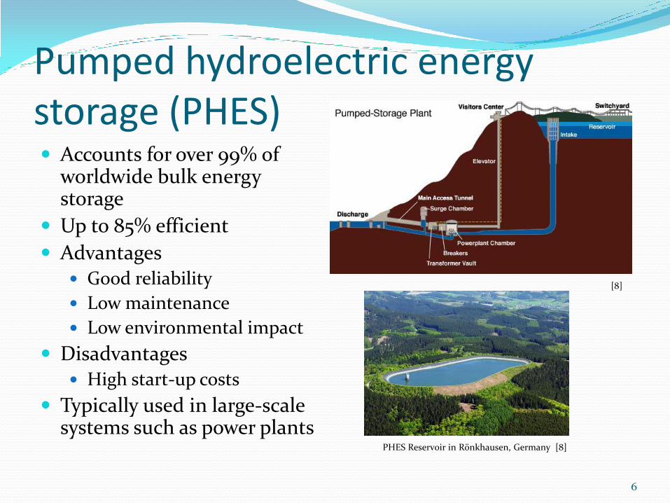
Pumped hydroelectric energy storage (PHES) Accounts for over 99% of
worldwide bulk energy storage
Up to 85% efficient
Advantages Good reliability
Low maintenance
Low environmental impact
Disadvantages High start-up costs
Typically used in large-scale systems such as power plants
6
PHES Reservoir in Rönkhausen, Germany
[8]
[8]

Compressed Air Energy Storage (CAES) Published overall
efficiencies typically around 50%
Highly reliable
Greater complexity than comparable storage methods
Typically used on very large scales
7
[10]

Design Approach
8
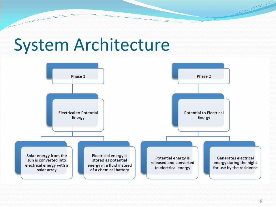
System Architecture
9

Functional Model
10
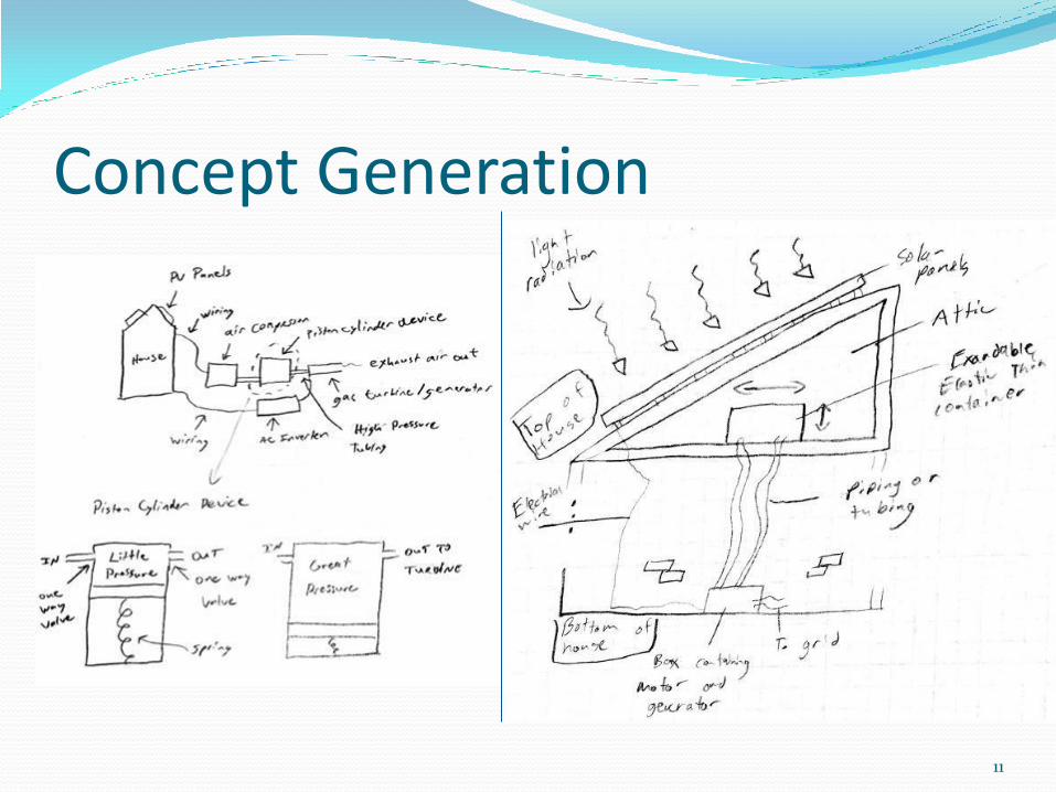
Concept Generation
11

PHES Architecture
12 (Not to scale)
House

Concept Selection – High-level Analysis Published efficiency values
for water turbines range from 60% to 90%
Published efficiencies for generators range from 80% to 95%
At minimum efficiency, this translates to a reservoir of about 5.6% the volume of an Olympic swimming pool at 62 m to meet power and energy requirements
13
System Parameters to Provide 1 kW Power for 11.4 h Using an 11 mm Nozzle

Results of High-level Analysis Stored energy is a
function of both reservoir height and volume
𝐸 = 𝑚𝑔ℎ = 𝜌𝑉𝑔ℎ
Power is a function of height:
𝑃 =𝑑𝐸
𝑑𝑡= 𝑚 𝑔ℎ
14
Needed Volume vs Height for 1 kW Power and 11.4 kWh Energy for No Loss, Max. Expected Efficiency, and Min.
Expected Efficiency

Compressed Air
𝑤𝑜𝑣 =𝑛
𝑛 − 1𝑃𝑖𝑛 1 −
𝑃𝑜𝑢𝑡𝑃𝑖𝑛
𝑛−1𝑛
𝑤𝑜𝑣 = Specific work that can be stored
n = value related to the conditions of the system
𝑃𝑜𝑢𝑡 = the pressure outside of the tank
𝑃𝑖𝑛 =denotes the pressure inside of the tank.

Compressed Air
𝑤𝑜𝑢𝑣 =𝑛
𝑛 − 1𝑃𝑚 1 −
𝑃𝑜𝑢𝑡𝑃𝑚
𝑛−1𝑛
𝑃𝑚= working pneumatic pressure
Replacing 𝑃𝑖𝑛 with 𝑃𝑚
𝑤𝑜𝑢𝑣 = wasted energy density

Tank Storage Needed
𝑤𝑜𝑒𝑣 = 𝑤𝑜𝑣 −𝑤𝑜𝑢𝑣
𝑉𝑖𝑛𝑡 =𝐸𝑠𝑡𝑤𝑜𝑒𝑣

Compressed Air System Efficiency
𝜂𝑠𝑡𝑜𝑟 =𝐸2𝐸1
= 43% 𝜂𝑥,𝑡 =𝑊𝑡
𝐸2= 36%
𝜂𝑠𝑡𝑜𝑟 = 𝐸𝑓𝑓𝑖𝑐𝑖𝑐𝑒𝑛𝑐𝑦 𝑜𝑓 𝑡ℎ𝑒 𝑆𝑡𝑜𝑟𝑎𝑔𝑒 𝑇𝑎𝑛𝑘
𝜂𝑥,𝑡 = 𝐸𝑓𝑓𝑖𝑐𝑖𝑒𝑛𝑐𝑦 𝑜𝑓 𝑡ℎ𝑒 𝑇𝑢𝑟𝑏𝑖𝑛𝑒 𝐸1 = 𝐸𝑛𝑒𝑟𝑔𝑦 𝑓𝑟𝑜𝑚 𝑆𝑡𝑜𝑟𝑎𝑔𝑒 𝐼𝑛𝑙𝑒𝑡
𝐸2 = 𝐸𝑛𝑒𝑟𝑔𝑦 𝑓𝑟𝑜𝑚 𝑡ℎ𝑒 𝑆𝑡𝑜𝑟𝑎𝑔𝑒 𝑂𝑢𝑡𝑙𝑒𝑡 𝑊𝑡 = 𝑇𝑢𝑟𝑏𝑖𝑛𝑒 𝑊𝑜𝑟𝑘

Energy Conversion Turgo and Pelton turbines
operate in air
Francis and propeller turbines operate submerged
All shown practical at a small-scale
19
(From Williamson, et al. [11])
[12]

Dynamic System-level Model
20
𝑐 𝐼𝑎𝑟𝑚𝑎𝑡𝑢𝑟𝑒 𝐼𝑡𝑢𝑟𝑏𝑖𝑛𝑒
𝑇,𝜔
𝑇𝐿
𝑅𝑎 𝐿 𝑅𝐿 𝑉𝑏
𝑖𝑎
𝑉𝑎 𝑘𝑏𝜔 − 𝑖𝑎(𝑅𝐿 + 𝑅𝑎) = 0
𝐼𝑒𝜔 = 𝑇 − 𝑇𝐿 − 𝑐𝜔
𝑇𝐿 = 𝑘𝑇𝑖𝑎 =𝑘𝑏𝑘𝑇
𝑅𝐿 + 𝑅𝑎𝜔
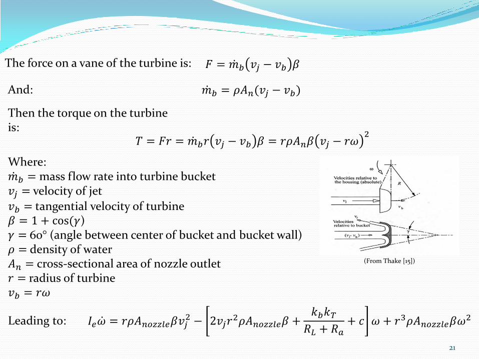
The force on a vane of the turbine is: 𝐹 = 𝑚 𝑏 𝑣𝑗 − 𝑣𝑏 𝛽
Where: 𝑚 𝑏 = mass flow rate into turbine bucket 𝑣𝑗 = velocity of jet
𝑣𝑏 = tangential velocity of turbine 𝛽 = 1 + cos(𝛾) 𝛾 = 60° (angle between center of bucket and bucket wall) 𝜌 = density of water 𝐴𝑛 = cross-sectional area of nozzle outlet 𝑟 = radius of turbine 𝑣𝑏 = 𝑟𝜔
And: 𝑚 𝑏 = 𝜌𝐴𝑛(𝑣𝑗 − 𝑣𝑏)
Then the torque on the turbine is:
𝑇 = 𝐹𝑟 = 𝑚 𝑏𝑟 𝑣𝑗 − 𝑣𝑏 𝛽 = 𝑟𝜌𝐴𝑛𝛽 𝑣𝑗 − 𝑟𝜔2
21
(From Thake [15])
𝐼𝑒𝜔 = 𝑟𝜌𝐴𝑛𝑜𝑧𝑧𝑙𝑒𝛽𝑣𝑗2 − 2𝑣𝑗𝑟
2𝜌𝐴𝑛𝑜𝑧𝑧𝑙𝑒𝛽 +𝑘𝑏𝑘𝑇
𝑅𝐿 + 𝑅𝑎+ 𝑐 𝜔 + 𝑟3𝜌𝐴𝑛𝑜𝑧𝑧𝑙𝑒𝛽𝜔
2 Leading to:

Experimental Set-up The model was validated
by simulating a raised reservoir using a fluid bench and pump
22

Model Validation 6, 8, 10, 12, and 16 mm
nozzles tested Model accurate within 7%
of results on average for 10 and 12 mm nozzles
Accounting for loss due to air resistance and the support bearing brings model within 6% of results 1.2 × 10⁻³ Ns/m added
to damping coefficient
Smaller and larger nozzles less accurate: 27% average for 6 and 8
mm 14% average for 16 mm
23

Experimental Results Measured efficiency up
to about 40%
(power output
total kinetic jet power)
10 mm nozzle
Flow rate of 15.8 GPM
Total hydraulic head of 10.4 m
Max. Overall efficiency of about 32%
(power output
power potential)
24

Design of Experiments – What factors most significantly impact efficiency?
25
Level Nozzle Size Motor Speed
Load
1 8 mm 40 Hz 35 Ω
2 10 mm 45 Hz 50 Ω
3 12 mm 50 Hz 65 Ω
Parameter Effect
Gross head Flow rate
Pipe diameter Frictional losses at pipe walls
Pipe components
Frictional losses due changes in flow direction
Number of nozzles
Total power input to turbine
Nozzle geometry
Flow rate, jet velocity
Water jet position
Total power input to turbine
Load on generator
Induced torque on turbine
26
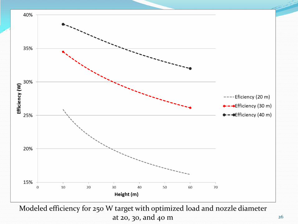
Modeled efficiency for 250 W target with optimized load and nozzle diameter at 20, 30, and 40 m
Conclusions and Future Work Target of 1 kW power output may be difficult to
achieve with great efficiency
Expectation is that residence is grid-connected
System is most cost effective by providing little power for a long time
System could be implemented in poor or remote locations, especially where local topography permits low-cost installation of raised reservoir
Further analysis and concurrent optimization of generator and turbine efficiency
27
References
28
1. Zimmerman, D. L., 2011. Residential Solar Energy in the Valley: A Feasibility Assessment and Carbon Mitigation (Master’s Thesis). Retrieved from James Madison University files database.
2. http://www.jadoopower.com/storage.php?Energy-Storage-Solar-VRLA-Batteries-4 3. http://www.solarenergy.gen.in/ 4. Nagel, J. K., (2012). Two-phase Energy System (Project proposal to Valley 25x’25). Source provided by Dr. Nagel. 5. October 25, 2012. Basic Tutorials: Storage Batteries. http://www.freesunpower.com/batteries.php. Free Sun Power. 6. October 25, 2012. Packing some power. http://www.economist.com/node/21548495?frsc=dg|a. The Economist. 7. Levine, J. G., 2003. Pumped Hydroelectric Energy Storage and Spatial Diversity of Wind Resources as Methods of
Improving Utilization of Renewable Energy Sources (Master’s Thesis). Retrieved from University of Colorado Boulder files database.
8. http://large.stanford.edu/courses/2012/ph240/doshay1/ 9. Young-Min K., Jange-Hee L., Seok-Jeon K., Favrat, D., 2012. Potential and Evolution of Compressed Air Energy
Storage: Energy and Exergy Analyses. Entropy 14 (8), 1501-1521. 10. http://www.pge.com/web/includes/images/about/environment/pge/cleanenergy/caes.jpg 11. Williamson, S., Stark, B., Booker, J., 2014. Low head pico hydro turbine selection using a multi-criteria analysis.
Renewable Energy 61, 43-50. 12. http://images.cpbay.com/uploadfile/comimg/big/Runner-of-Francis-Turbine-200KW-271584.jpg 13. Proczka, J., Muralidharan, K., Villela, D., Simmons, J., & Frantziskonis, G. (2013). Guidelines for the pressure and
efficient sizing of pressure vessels for compressed air energy storage. Energy Conversion and Management, 65, 597-605. Retrieved October 30, 2013, from the Science Direct database.
14. Elmegaard, B., Brix, W. Efficiency of Compressed Air Energy Storage. Retrieved from http://orbit.dtu.dk/fedora/objects/orbit:72193/datastreams/file_6324034/content
15. Thake, J., 2000. The Micro-hydro Pelton Turbine Manual. ITDG Publishing, London.